EP3031237B1 - Generating precoders for joint transmission from multiple transmission points to multiple user equipments in a downlink coordinated multipoint transmission/reception communications system - Google Patents
Generating precoders for joint transmission from multiple transmission points to multiple user equipments in a downlink coordinated multipoint transmission/reception communications system Download PDFInfo
- Publication number
- EP3031237B1 EP3031237B1 EP14835060.6A EP14835060A EP3031237B1 EP 3031237 B1 EP3031237 B1 EP 3031237B1 EP 14835060 A EP14835060 A EP 14835060A EP 3031237 B1 EP3031237 B1 EP 3031237B1
- Authority
- EP
- European Patent Office
- Prior art keywords
- pmi
- transmission
- precoders
- serving
- tps
- Prior art date
- Legal status (The legal status is an assumption and is not a legal conclusion. Google has not performed a legal analysis and makes no representation as to the accuracy of the status listed.)
- Active
Links
- 230000005540 biological transmission Effects 0.000 title claims description 30
- 238000004891 communication Methods 0.000 title claims description 7
- 238000000034 method Methods 0.000 claims description 33
- 239000011159 matrix material Substances 0.000 claims description 16
- 230000001427 coherent effect Effects 0.000 claims description 13
- 239000013598 vector Substances 0.000 claims description 5
- 238000005259 measurement Methods 0.000 description 8
- 238000005457 optimization Methods 0.000 description 4
- 230000008901 benefit Effects 0.000 description 3
- 230000001419 dependent effect Effects 0.000 description 2
- 241000760358 Enodes Species 0.000 description 1
- 239000000654 additive Substances 0.000 description 1
- 230000000996 additive effect Effects 0.000 description 1
- 238000013461 design Methods 0.000 description 1
- 230000000694 effects Effects 0.000 description 1
- 238000012986 modification Methods 0.000 description 1
- 230000004048 modification Effects 0.000 description 1
Images


Classifications
-
- H—ELECTRICITY
- H04—ELECTRIC COMMUNICATION TECHNIQUE
- H04B—TRANSMISSION
- H04B7/00—Radio transmission systems, i.e. using radiation field
- H04B7/02—Diversity systems; Multi-antenna system, i.e. transmission or reception using multiple antennas
- H04B7/022—Site diversity; Macro-diversity
- H04B7/024—Co-operative use of antennas of several sites, e.g. in co-ordinated multipoint or co-operative multiple-input multiple-output [MIMO] systems
-
- H—ELECTRICITY
- H04—ELECTRIC COMMUNICATION TECHNIQUE
- H04B—TRANSMISSION
- H04B7/00—Radio transmission systems, i.e. using radiation field
- H04B7/02—Diversity systems; Multi-antenna system, i.e. transmission or reception using multiple antennas
- H04B7/04—Diversity systems; Multi-antenna system, i.e. transmission or reception using multiple antennas using two or more spaced independent antennas
- H04B7/06—Diversity systems; Multi-antenna system, i.e. transmission or reception using multiple antennas using two or more spaced independent antennas at the transmitting station
- H04B7/0613—Diversity systems; Multi-antenna system, i.e. transmission or reception using multiple antennas using two or more spaced independent antennas at the transmitting station using simultaneous transmission
- H04B7/0615—Diversity systems; Multi-antenna system, i.e. transmission or reception using multiple antennas using two or more spaced independent antennas at the transmitting station using simultaneous transmission of weighted versions of same signal
- H04B7/0619—Diversity systems; Multi-antenna system, i.e. transmission or reception using multiple antennas using two or more spaced independent antennas at the transmitting station using simultaneous transmission of weighted versions of same signal using feedback from receiving side
- H04B7/0621—Feedback content
- H04B7/0626—Channel coefficients, e.g. channel state information [CSI]
-
- H—ELECTRICITY
- H04—ELECTRIC COMMUNICATION TECHNIQUE
- H04B—TRANSMISSION
- H04B7/00—Radio transmission systems, i.e. using radiation field
- H04B7/02—Diversity systems; Multi-antenna system, i.e. transmission or reception using multiple antennas
- H04B7/04—Diversity systems; Multi-antenna system, i.e. transmission or reception using multiple antennas using two or more spaced independent antennas
- H04B7/06—Diversity systems; Multi-antenna system, i.e. transmission or reception using multiple antennas using two or more spaced independent antennas at the transmitting station
- H04B7/0613—Diversity systems; Multi-antenna system, i.e. transmission or reception using multiple antennas using two or more spaced independent antennas at the transmitting station using simultaneous transmission
- H04B7/0615—Diversity systems; Multi-antenna system, i.e. transmission or reception using multiple antennas using two or more spaced independent antennas at the transmitting station using simultaneous transmission of weighted versions of same signal
- H04B7/0619—Diversity systems; Multi-antenna system, i.e. transmission or reception using multiple antennas using two or more spaced independent antennas at the transmitting station using simultaneous transmission of weighted versions of same signal using feedback from receiving side
- H04B7/0636—Feedback format
- H04B7/0639—Using selective indices, e.g. of a codebook, e.g. pre-distortion matrix index [PMI] or for beam selection
-
- H—ELECTRICITY
- H04—ELECTRIC COMMUNICATION TECHNIQUE
- H04L—TRANSMISSION OF DIGITAL INFORMATION, e.g. TELEGRAPHIC COMMUNICATION
- H04L1/00—Arrangements for detecting or preventing errors in the information received
- H04L1/0001—Systems modifying transmission characteristics according to link quality, e.g. power backoff
- H04L1/0023—Systems modifying transmission characteristics according to link quality, e.g. power backoff characterised by the signalling
- H04L1/0026—Transmission of channel quality indication
-
- H—ELECTRICITY
- H04—ELECTRIC COMMUNICATION TECHNIQUE
- H04L—TRANSMISSION OF DIGITAL INFORMATION, e.g. TELEGRAPHIC COMMUNICATION
- H04L5/00—Arrangements affording multiple use of the transmission path
- H04L5/003—Arrangements for allocating sub-channels of the transmission path
- H04L5/0032—Distributed allocation, i.e. involving a plurality of allocating devices, each making partial allocation
- H04L5/0035—Resource allocation in a cooperative multipoint environment
-
- H—ELECTRICITY
- H04—ELECTRIC COMMUNICATION TECHNIQUE
- H04L—TRANSMISSION OF DIGITAL INFORMATION, e.g. TELEGRAPHIC COMMUNICATION
- H04L1/00—Arrangements for detecting or preventing errors in the information received
- H04L1/0001—Systems modifying transmission characteristics according to link quality, e.g. power backoff
- H04L1/0023—Systems modifying transmission characteristics according to link quality, e.g. power backoff characterised by the signalling
- H04L1/0028—Formatting
- H04L1/0031—Multiple signaling transmission
Definitions
- the present invention relates to generating precoders for joint transmission (JT) from multiple transmission points to multiple user equipments in a Downlink Coordinated Multi-Point transmission/reception (DL CoMP) communications system.
- JT joint transmission
- DL CoMP Downlink Coordinated Multi-Point transmission/reception
- CoMP Coordinated Multi-Point (the abbreviation CoMP often also means Coordinated Multi-Point transmission/reception, as will be evident from the context)
- CQI Channel Quality Indicator CSI Channel State Information - CSI includes PMI, RI, CQI (see below) DL Downlink DMRS Demodulation Reference Signal eNodeB Evolved NodeB (i.e. evolved base station) JT Joint Transmission MMSE Minimum Mean Squared Error PMI Precoder Matrix Indicator SINR Signal to Interference plus Noise Ratio RI Rank Indicator TP Transmission Point UE User Equipment
- JT - DL CoMP Joint Transmission Downlink Coordinated Multi-Point transmission/reception
- Fig. 1 schematically represents JT in a DL CoMP system.
- the system includes multiple TPs (these may be eNodeBs), each TP being equipped with multiple antennas, and multiple UEs where each UE is also equipped with multiple antennas.
- the multiple TPs transmit data to the multiple UEs on the same time-frequency.
- the transmission is carried out with CoMP precoders which are generated based on (i.e. generated from the knowledge of) the channel state information (CSI).
- CSI channel state information
- Each UE feeds back CSI (which includes RI, PMI and CQI) to its serving TP via uplink, as illustrated in Fig. 2 .
- CSI measurement for each UE there are as many CSI configurations as there are TPs involved in JT - DL CoMP.
- Figs. 3A and 3B show CSI measurement for a UE involved in JT - DL CoMP with two TPs.
- the CSI config#0 is for TP#0 (the serving TP)
- the CSI config#1 is for TP#1 (the neighbouring TP).
- a JT DL CoMP system having N TP TPs and N UE UEs may be described mathematically as set out below.
- N RX denote the number of receive antennas at each UE
- H in (size N RX ⁇ ⁇ n ) denote the channel between the n -th TP and the i- th UE.
- V i size N TX ⁇ RI i ) denote the precoder for the i -th UE.
- Precoding is dependent on PMI which is part of the CSI. (Recall that CSI is fed back by a UE to its serving TP via uplink.)
- PMI which is part of the CSI.
- p in denote the PMI corresponding to H in . Note that in a 2-stage PMI codebook system, p in is a pair PMI#1 and PMI#2.
- the precoder W in (of size ⁇ n ⁇ RI i ) associated with the reported PMI p in is used for precoding data to send from the n -th TP to the i -th UE.
- Precoding in this way is not optimal and it may be desirable to provide an improved or at least an alternative way of generating precoders.
- US 2013/089159 A1 discloses a method for deciding a precoding vector of coordinated multipoint transmission (CoMP) for at least one user equipment based on channel state information for CoMP received from the user equipment, wherein the channel state information includes inter-cell correlation property between a serving cell serving the user equipment and a cooperating cell for CoMP.
- CoMP coordinated multipoint transmission
- US 2011/103287 A1 discloses a method of operating a communication device including determining a first coordinated multipoint (CoMP) mode, electronically receiving feedback from a user device in the uniform feedback format, and determining transmission parameters of the first CoMP mode.
- the first CoMP mode includes one of a plurality of CoMP modes, and each of the plurality of CoMP modes is configured to operate using a uniform feedback format.
- US 2013/021925 A1 discloses a method for configuring coordinated multipoint (CoMP) transmission by an eNode B.
- Feedback information is received from a user equipment (UE).
- a CoMP transmission measurement set is determined.
- the CoMP transmission measurement set is sent to the UE.
- a channel state information (CSI) report of the CoMP measurement set is received from the UE.
- a CoMP transmission method used for each CoMP transmission point in the CoMP measurement set is selected.
- the invention provides a method and a system as disclosed in the appended independent claims.
- Optional, but advantageous features are disclosed in the appended dependent claims.
- Embodiments of the present invention provide MMSE precoders based (at least somewhat) on the joint transmit & receive optimization methods discussed in the above academic papers. However, unlike the methods in these academic papers, the present invention does not require knowledge of the channel to generate MMSE precoders. Instead (and in contrast), embodiments of the invention require only the PMI, which is fed back by UEs to serving TPs, as shown in Fig. 2 .
- the precoder according to the particular embodiments of the invention discussed below will be referred to as the j-MMSE precoder.
- the individual j-MMSE precoder V in is computed using the joint transmit and receive MMSE optimization as follows.
- ⁇ RI denote the fixed codebook of representative channel matrices which is generated from the PMI codebook(s). There are different ⁇ RI for different RI.
- ⁇ in be the representative for the channel H in .
- the representative channel is obtained as follows:
- the Lagrange multiplier ⁇ n is computed as follows.
- the total j-MMSE precoder V i is computed using the joint transmit and receive MMSE optimization as follows:
- the Lagrange multiplier ⁇ is obtained as follows.
- the following noise variance estimation may be used for both non-coherent and coherent precoding.
- the method estimates the UE's noise variance from the reported CQI for the serving TP is as follows:
- rank and CQI selection is necessary. From the as many as N TP reported PI in , the majority is selected as the single common RI i for the i -th UE. The selection can be done using the histogram. Then only CQI i n ⁇ ( l ) associated with the selected RI i are the candidates for CQI selection. The selection is carried out per codeword independently. The majority among the candidates is selected as the common CQI for the l -th codeword CQI i ( l ) . The selection can be done using the histogram.
- embodiments of the present invention do not require knowledge of the channel to generate the j-MMSE precoder. Rather, they require only the PMI which is fed back by UEs. This may provide a number of advantages. For instance, it may provide improved performance in comparison with methods which directly use reported PMI. Also, as is made evident above, the invention is applicable to both coherent and non-coherent precoding.
Landscapes
- Engineering & Computer Science (AREA)
- Signal Processing (AREA)
- Computer Networks & Wireless Communication (AREA)
- Quality & Reliability (AREA)
- Physics & Mathematics (AREA)
- Mathematical Physics (AREA)
- Mobile Radio Communication Systems (AREA)
Description
- The present invention relates to generating precoders for joint transmission (JT) from multiple transmission points to multiple user equipments in a Downlink Coordinated Multi-Point transmission/reception (DL CoMP) communications system.
- The following abbreviations are used herein:
CoMP Coordinated Multi-Point (the abbreviation CoMP often also means Coordinated Multi-Point transmission/reception, as will be evident from the context) CQI Channel Quality Indicator CSI Channel State Information - CSI includes PMI, RI, CQI (see below) DL Downlink DMRS Demodulation Reference Signal eNodeB Evolved NodeB (i.e. evolved base station) JT Joint Transmission MMSE Minimum Mean Squared Error PMI Precoder Matrix Indicator SINR Signal to Interference plus Noise Ratio RI Rank Indicator TP Transmission Point UE User Equipment - Also, the following mathematical notations are adopted herein:
- ▪ |a| denotes the absolute value of a;
- ▪ ∥a∥2 = |a(1)|2 +...+|a(N)|2 (unless stated otherwise);
- ▪ Ea denotes the expectation (or expected value) of a; and
- ▪ For any matrix A, A H denotes the conjugate transpose of A, and tr( A ) represents the operation of taking the trace of A.
- Joint Transmission Downlink Coordinated Multi-Point transmission/reception (JT - DL CoMP).
-
Fig. 1 schematically represents JT in a DL CoMP system. The system includes multiple TPs (these may be eNodeBs), each TP being equipped with multiple antennas, and multiple UEs where each UE is also equipped with multiple antennas. The multiple TPs transmit data to the multiple UEs on the same time-frequency. Generally, to minimise interferences between TPs and between UEs, the transmission is carried out with CoMP precoders which are generated based on (i.e. generated from the knowledge of) the channel state information (CSI). - Each UE feeds back CSI (which includes RI, PMI and CQI) to its serving TP via uplink, as illustrated in
Fig. 2 . - In CSI measurement, for each UE there are as many CSI configurations as there are TPs involved in JT - DL CoMP.
Figs. 3A and3B show CSI measurement for a UE involved in JT - DL CoMP with two TPs. TheCSI config# 0 is for TP#0 (the serving TP) and theCSI config# 1 is for TP#1 (the neighbouring TP). - A JT DL CoMP system having NTP TPs and NUE UEs may be described mathematically as set out below.
- Let τn denote the number of antennas at the n-th TP. The total number of transmit antennas NTX used in DL CoMP transmission is:

- Let NRX denote the number of receive antennas at each UE, and let H in (size NRX × τn ) denote the channel between the n-th TP and the i-th UE.
- Then the DL CoMP channel of the i-th UE (size NRX × NTX ) is:

- Let V i (size NTX × RIi ) denote the precoder for the i-th UE.
- The received signal at the i-th UE (y i ) is given by:

- Precoding is dependent on PMI which is part of the CSI. (Recall that CSI is fed back by a UE to its serving TP via uplink.) Let pin denote the PMI corresponding to H in . Note that in a 2-stage PMI codebook system, pin is a
pair PMI# 1 and PMI#2. - According to the 3GPP standard (TS 36.211), the precoder W in (of size τn × RIi ) associated with the reported PMI pin is used for precoding data to send from the n-th TP to the i-th UE. The total DL CoMP precoder is therefore given by:

PMI# 1 and PMI#2. - Precoding in this way is not optimal and it may be desirable to provide an improved or at least an alternative way of generating precoders.
- It is to be clearly understood that mere reference herein to previous or existing systems, methods, models, processes, procedures, practices, publications or other information, or to any problems or issues, does not constitute an acknowledgement or admission that any of those things individually or in any combination formed part of the common general knowledge of those skilled in the field, or that they are admissible prior art.
-
US 2013/089159 A1 discloses a method for deciding a precoding vector of coordinated multipoint transmission (CoMP) for at least one user equipment based on channel state information for CoMP received from the user equipment, wherein the channel state information includes inter-cell correlation property between a serving cell serving the user equipment and a cooperating cell for CoMP. -
US 2011/103287 A1 discloses a method of operating a communication device including determining a first coordinated multipoint (CoMP) mode, electronically receiving feedback from a user device in the uniform feedback format, and determining transmission parameters of the first CoMP mode. The first CoMP mode includes one of a plurality of CoMP modes, and each of the plurality of CoMP modes is configured to operate using a uniform feedback format. -
US 2013/021925 A1 discloses a method for configuring coordinated multipoint (CoMP) transmission by an eNode B. Feedback information is received from a user equipment (UE). A CoMP transmission measurement set is determined. The CoMP transmission measurement set is sent to the UE. A channel state information (CSI) report of the CoMP measurement set is received from the UE. A CoMP transmission method used for each CoMP transmission point in the CoMP measurement set is selected. - In one broad form, the invention provides a method and a system as disclosed in the appended independent claims. Optional, but advantageous features are disclosed in the appended dependent claims.
- The invention is defined by the appended claims. In the following, embodiments not falling within the scope of the claims should be understood as examples useful to understand the invention. The Detailed Description will make reference to a number of drawings as follows:
-
Fig. 1 is schematically represents a JT - DL CoMP system. -
Fig. 2 is schematically represents the way each UE feeds back CSI to its serving TP via uplink. -
Fig. 3A schematically illustrates CSI measurement for JT - DL CoMP. -
Fig. 3B schematically illustrates CSI measurement for JT - DL CoMP. -
Fig. 4 is a flowchart illustrating, for the case of non-coherent precoding, a method for generating j-MMSE precoders in accordance with the embodiment of the invention discussed below. -
Fig. 5 is a flowchart illustrating, for the case of non-coherent precoding, a method for computing the Lagrange multiplier for the n-th TP. -
Fig. 6 is a flowchart illustrating, for the case of coherent precoding, a method for generating j-MMSE precoders in accordance with the embodiment of the invention discussed below. -
Fig. 7 is a flowchart illustrating, for the case of coherent precoding, a method for computing the Lagrange multiplier for all TPs. -
Fig. 8 schematically illustrates the estimation of a UE's noise variance based on the reported CQI of the serving TP. -
Fig. 9 schematically illustrates RI and CQI collection from the reported RI and CQI for transmission to the i-th UE. - Joint transmit & receive optimisation methods have previously been proposed. See, for example, Sampath H. and Paulraj A., "Joint Transmit and Receive Optimization for High Data Rate Wireless Communication Using Multiple Antennas", Thirty-Third Asilomar Conference on Signals, Systems, and Computers, 1999, and Zhang J., et. al., "Joint Linear Transmitter and Receiver Design for Downlink of Multiuser MIMO Systems", IEEE Communications Letters, Vol. 9, No. 11, November 2005.
- Embodiments of the present invention provide MMSE precoders based (at least somewhat) on the joint transmit & receive optimization methods discussed in the above academic papers. However, unlike the methods in these academic papers, the present invention does not require knowledge of the channel to generate MMSE precoders. Instead (and in contrast), embodiments of the invention require only the PMI, which is fed back by UEs to serving TPs, as shown in
Fig. 2 . The precoder according to the particular embodiments of the invention discussed below will be referred to as the j-MMSE precoder. - In the case of non-coherent precoding, the individual j-MMSE precoder V in is computed using the joint transmit and receive MMSE optimization as follows.
- Let Ω RI denote the fixed codebook of representative channel matrices which is generated from the PMI codebook(s). There are different Ω RI for different RI.
- For RIi = NRX , the Ω RI contains matrices Ĥ(m), m = 1,... of size NRX × τn
- For RIi < NRX , the Ω RI contains vectors ĥ(m), m = 1,... of size τn × 1
- Let Ĥ in be the representative for the channel H in . The representative channel is obtained as follows:
- If RIi = NRX , then


- If RIi < NRX , then
- 1) Calculate correlation values:

- 2) Sort to find the NRX largest correlation values Cin (m 1) > Cin (m 2) >... > Cin (mN
RX ) and the NRX corresponding ĥ(m 1), ĥ(m 2),..., ĥ(mNRX ) to form the channel matrix
- Here W in (of size τn × RIi ) is the precoder in the 3GPP standard (TS 36.211) associated with the PMI pin . Note that, if the PMI consists of
PMI# 1 and PMI#2, then W in = W in(1) × W in(2). - Let (m) denote the m-th iteration of the procedure. The precoder is generated as follows:
- 1) (401) Initialize G in (m = 0) = J in , i=1,...,NUE . Here J in is a RIi × τn matrix with the (a,b)-th element being zero for a ≠ b and being 1 for a = b.
- 2) (402) Compute V in (m + 1) using G in (m) and the Lagrange multiplier υn for i = 1,..., NUE as follows.

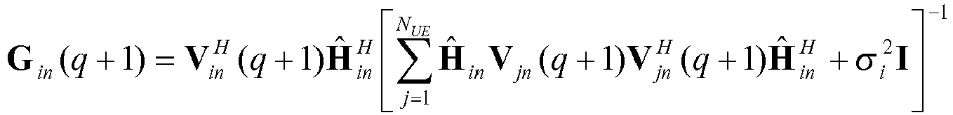
- 3) (403) Compute G in (m + 1) using V in (m + 1) and the given noise variance estimate


- 4) (404) Compute

- 5) (405) increment m and repeat step 2), step 3) and step 4) until


- 6) (406) Output V in (m + 1), i = 1,...,NUE.
- For each of the n-th TP, the Lagrange multiplier υn is computed as follows.
- 1) (501) Compute λk as

- 2) (502) Set υ min and υ max
- 3) (503) Set υn = (υ max + υ min)/2.
- 4) (504) Compute the following quantity

- 5) (505) Check if P̂ n > Pn and if so set υ min = υn otherwise set υ max = υn. Here Pn is the transmit power of the n-th TP.
- 6) (506) Repeat step 3), step 4) and step 5) until |P̂n - Pn | < ε. Here ε is the convergent threshold.
- 7) (507) Output υn.
- In the case of coherent precoding, the total j-MMSE precoder V i is computed using the joint transmit and receive MMSE optimization as follows:
- First the individual representative channel Ĥ in is found as in the non-coherent case discussed above. Then the total channel is generated by:

- Let (m) denote the m-th iteration of the procedure. The precoder is generated as follows:
- a) (601) Initialize G i (m = 0) = J i , i = 1,...,NUE. Here J i is a RIi ×NTX matrix with the (a,b)-th element being zero for a ≠ b and being 1 for a = b.
- b) (602) Compute V i (m+1) using G i (m) and the Lagrange multiplier υ for i=1,..., NUE as follows.

- c) (603) Compute G i (m+1) using V i (m+1) and the given noise variance estimate


- d) (604) Compute
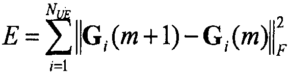
- e) (605) increment m and repeat step b), step c) and step d) until

- f) (606) Output V i (m+1), i = 1, ..., NUE
- The Lagrange multiplier υ is obtained as follows.
- 1) (701) Compute λk as

- 2) (702) Set υ min and υ max
- 3) (703) Set υ = (υ max + υ min)/2.
- 4) (704) Compute the following quantity
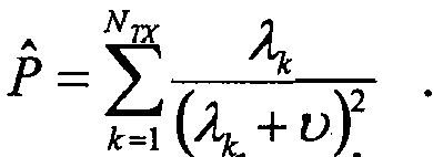
- 5) (705) Check if P̂ > P and if so set υ min = υ otherwise set υmax = υ. Here P is the total transmit power,

- 6) (706) Repeat step 3), step 4) and step 5) until |P̂ - P| < ε. Here ε is the convergent threshold.
- 7) (707) Output the Lagrange multiplier υ.
- The following noise variance estimation may be used for both non-coherent and coherent precoding. The method estimates the UE's noise variance from the reported CQI for the serving TP is as follows:
- 1) (801) Find SINRil based on the SINR thresholds in the CQI table.
- 2) (802) Calculate


- Because, for a given UE, all TPs have common transmission rank and common CQI, it follows that rank and CQI selection is necessary. From the as many as NTP reported PIin , the majority is selected as the single common RIi for the i-th UE. The selection can be done using the histogram. Then only CQIi n̂ (l) associated with the selected RIi are the candidates for CQI selection. The selection is carried out per codeword independently. The majority among the candidates is selected as the common CQI for the l-th codeword CQIi (l). The selection can be done using the histogram.
- As discussed above, embodiments of the present invention do not require knowledge of the channel to generate the j-MMSE precoder. Rather, they require only the PMI which is fed back by UEs. This may provide a number of advantages. For instance, it may provide improved performance in comparison with methods which directly use reported PMI. Also, as is made evident above, the invention is applicable to both coherent and non-coherent precoding.
- In the present specification and claims (if any), the word 'comprising' and its derivatives including 'comprises' and 'comprise' include each of the stated integers but does not exclude the inclusion of one or more further integers.
- Reference throughout this specification to 'one embodiment' or 'an embodiment' means that a particular feature, structure, or characteristic described in connection with the embodiment is included in at least one embodiment of the present invention. Thus, the appearance of the phrases 'in one embodiment' or 'in an embodiment' in various places throughout this specification are not necessarily all referring to the same embodiment. Furthermore, the particular features, structures, or characteristics may be combined in any suitable manner in one or more combinations.
- In compliance with the statute, the invention has been described in language more or less specific to structural, systems or methodical features. It is to be understood that the invention is not limited to specific features shown or described since the means herein described comprises preferred forms of putting the invention into effect. The invention is, therefore, claimed in any of its forms or modifications within the proper scope of the appended claims (if any) appropriately interpreted by those skilled in the art.
- This application is based upon and claims the benefit of priority from Australia Patent Application No.
2013902955, filed on August 7, 2013 -
- TP0
- SERVING TP
- TP1
- NEIGHBOURING TP
Claims (10)
- A method for generating precoders for joint transmission, JT, in a downlink coordinated multi-point transmission/reception, DL CoMP, wireless communications system, the system including a plurality of transmission points, TPs, operable to communicate with a plurality of user equipments, UEs, wherein each UE has one of the TPs as its serving TP, and the method comprises:transmitting channel state information, CSI, from each UE to its serving TP, wherein the transmitted CSI includes precoder matrix indicators, PMI, andusing the PMI to generate precoders for transmission of data from the plurality of TPs to the plurality of UEs;wherein using the PMI to generate precoders involves using the PMI to find a representative matrix, Ĥ in , representing a channel matrix, H in , between an n-th TP and an i-th UE;wherein a fixed codebook, Ω RI , of representative matrices is generated from PMI codebook(s), wherein the CSI transmitted from each UE to its serving TP includes a rank indicator, RI, and wherein Ω RI is different for different RIs;wherein, if an RI for the i-th UE, RIi , is equal to a number of receive antennas of the UE, NRX , then Ω RI contains matrices Ĥ(m), m≥1, of size NRX ×τn, wherein τn is a number of transmit antennas at the n-th TP;wherein, if RIi is less than NRX then Ω RI contains vectors ĥ(m), m≥1, of size τn × 1; andwherein, for RIi = NRX , the representative matrix Ĥ in is found by:


- The method as claimed in claim 1 wherein, for RIi < NRX, the representative matrix Ĥ in is found by:a) calculating correlation values as:
 b) sorting to find NRX largest correlation values Cin (m 1) > Cin (m 2) > ... > Cin (mN
RX ) and their corresponding vectors ĥ(m 1), ĥ(m 2),..., ĥ(mNRX ) to form the channel matrix
- The method as claimed in claim 2, wherein non-coherent precoding is used and the method further comprises using the representative matrix Ĥ in , a Lagrange multiplier υn and a noise variance estimate

- The method as claimed in claim 3, wherein the precoders V in are computed using an iterative procedure.
- The method as claimed in claim 4, wherein the precoders V in are computed using the following iterative procedure where (q) denotes a q-th iteration:a) initialize a quantity G in (q = 0) = J in , i = 1,..., NUE, where J in is a RIi × τn matrix with a (a,b)-th element being zero for a ≠ b and 1 for a = b ;b) compute V in (q + 1) using G in (q) and the Lagrange multiplier υn for i = 1,..., NUE as follows:
 c) compute G in (q+1) using V in (q + 1) and the noise variance estimate
 d) compute
 e) repeat step b), step c) and step d) until
 f) output V in (q + 1), i = 1, ..., NUE.
 - The method as claimed in claim 5, wherein the Lagrange multiplier υn for the n-th TP is computed using the following procedure:a) compute λk as
 b) set υ min and υ max;c) set υn =(υ max+υ min/2;d) compute a quantity
 e) check if P̂n > Pn and if so set υ min = υn otherwise set υ max = υn , where Pn is a transmit power of the n-th TP;f) repeat step c), step d) and step e) until |P̂n - Pn | < ε, where ε is a convergent threshold; andg) output υn.
 - The method as claimed in claim 3, wherein the CSI transmitted from each UE to its serving TP includes a channel quality indicator, CQI, and the noise variance estimate
 a) find a signal to interference plus noise ratio, SINRil , based on thresholds in the CQI table; andb) calculate

- The method as claimed in claim 7, wherein, from up to NTP reported RIin , a majority is selected as a single common RIi for the i-th UE.
- The method as claimed in claim 8, wherein only CQIi n̂ (l) associated with the selected RIi are candidates for CQI selection, the selection is carried out per codeword independently, and a majority among the candidates is selected as a common CQI for the l-th codeword CQIi (l).
- A downlink coordinated multi-point transmission/reception, DL CoMP, wireless communications system in which joint transmission, JT, is performed between a plurality of transmission points, TPs, and a plurality of user equipments, UEs, wherein each UE has one of the TPs as its serving TP, channel state information, CSI, is transmitted from each UE to its serving TP, the transmitted CSI includes precoder matrix indicators, PMI, and the PMI is used to generate precoders for transmission of data from the plurality of TPs to the plurality of UEs;
wherein using the PMI to generate precoders involves using the PMI to find a representative matrix, Ĥ in , representing the channel, H in , between an n-th TP and an i-th UE;
wherein a fixed codebook, Ω RI , of representative matrices is generated from PMI codebook(s), the CSI transmitted from each UE to its serving TP includes a rank indicator, RI, and Ω RI is different for different RIs;
wherein, if an RI for the i-th UE, RIi , is equal to a number of receive antennas of the UE, NRX , then Ω RI contains matrices Ĥ(m), m≥1, of size NRX ×τn, wherein τn is a number of transmit antennas at the n-th TP;
wherein, if RIi is less than NRX then Ω RI contains vectors ĥ(m), m≥1, of size τn × 1; and
wherein, for RIi = NRX , the representative matrix Ĥ in is found by:

Applications Claiming Priority (2)
| Application Number | Priority Date | Filing Date | Title |
|---|---|---|---|
| AU2013902955A AU2013902955A0 (en) | 2013-08-07 | Generating precoders for joint transmission from multiple transmission points to multiple user equipments in a downlink coordinated multipoint transmission/reception communications system | |
| PCT/JP2014/071349 WO2015020232A1 (en) | 2013-08-07 | 2014-08-05 | Generating precoders for joint transmission from multiple transmission points to multiple user equipments in a downlink coordinated multipoint transmission/reception communications system |
Publications (3)
| Publication Number | Publication Date |
|---|---|
| EP3031237A1 EP3031237A1 (en) | 2016-06-15 |
| EP3031237A4 EP3031237A4 (en) | 2017-03-15 |
| EP3031237B1 true EP3031237B1 (en) | 2019-06-05 |
Family
ID=52461551
Family Applications (1)
| Application Number | Title | Priority Date | Filing Date |
|---|---|---|---|
| EP14835060.6A Active EP3031237B1 (en) | 2013-08-07 | 2014-08-05 | Generating precoders for joint transmission from multiple transmission points to multiple user equipments in a downlink coordinated multipoint transmission/reception communications system |
Country Status (5)
| Country | Link |
|---|---|
| US (1) | US9825676B2 (en) |
| EP (1) | EP3031237B1 (en) |
| JP (1) | JP6094718B2 (en) |
| CN (1) | CN105409282B (en) |
| WO (1) | WO2015020232A1 (en) |
Families Citing this family (2)
| Publication number | Priority date | Publication date | Assignee | Title |
|---|---|---|---|---|
| WO2022209213A1 (en) * | 2021-03-30 | 2022-10-06 | ソニーグループ株式会社 | Wireless communication device and method |
| EP4472280A4 (en) * | 2022-01-28 | 2025-10-01 | Ntt Docomo Inc | TERMINAL DEVICE, WIRELESS COMMUNICATION METHOD AND BASE STATION |
Family Cites Families (17)
| Publication number | Priority date | Publication date | Assignee | Title |
|---|---|---|---|---|
| US8406171B2 (en) * | 2008-08-01 | 2013-03-26 | Texas Instruments Incorporated | Network MIMO reporting, control signaling and transmission |
| CN101729131B (en) | 2008-11-03 | 2014-06-04 | 夏普株式会社 | Wireless communication system and pre-coding method |
| EP2448136B1 (en) | 2009-06-23 | 2019-01-23 | Alcatel Lucent | Method for channel status information feedback and device thereof |
| KR101568291B1 (en) * | 2009-07-10 | 2015-11-20 | 삼성전자주식회사 | Terminal and base station, and a method of operation of the terminal |
| EP2471208B1 (en) | 2009-08-24 | 2020-09-23 | Nokia Solutions and Networks Oy | Channel-adaptive transmission in a distributed coordinated multi-point transmission system |
| US9520931B2 (en) * | 2009-11-02 | 2016-12-13 | Huawei Technologies Co., Ltd. | System and method for unified feedback in a communication system |
| JP5268983B2 (en) * | 2010-04-05 | 2013-08-21 | 株式会社エヌ・ティ・ティ・ドコモ | COMMUNICATION CONTROL METHOD, MOBILE STATION DEVICE, AND BASE STATION DEVICE |
| JP5296004B2 (en) * | 2010-04-23 | 2013-09-25 | 株式会社エヌ・ティ・ティ・ドコモ | Feedback information transmission method, mobile station apparatus and base station apparatus |
| CN102948085B (en) * | 2010-06-18 | 2016-08-24 | 日本电气株式会社 | Precoding Techniques for Downlink Coordinated Multipoint Transmission in Radio Communication Systems |
| EP3629491A1 (en) | 2011-01-07 | 2020-04-01 | InterDigital Patent Holdings, Inc. | Communicating channel state information (csi) of multiple transmission points |
| US9735844B2 (en) * | 2011-05-09 | 2017-08-15 | Texas Instruments Incorporated | Channel feedback for coordinated multi-point transmissions |
| US20130021925A1 (en) * | 2011-07-22 | 2013-01-24 | Sharp Laboratories Of America, Inc. | Coordinated multipoint (comp) transmission method selection and feedback requirements |
| US20130083681A1 (en) * | 2011-09-30 | 2013-04-04 | Research In Motion Limited | Methods of Channel State Information Feedback and Transmission in Coordinated Multi-Point Wireless Communications System |
| KR101607416B1 (en) * | 2011-11-07 | 2016-03-29 | 모토로라 모빌리티 엘엘씨 | Method and apparatus for csi feedback for joint processing schemes in an orthogonal frequency division multiplexing communication system with coordinated multi-point transmission |
| WO2013112829A1 (en) | 2012-01-27 | 2013-08-01 | Nec Laboratories America, Inc. | Coordinated multiple point transmission and reception |
| KR20150037755A (en) * | 2012-07-06 | 2015-04-08 | 엘지전자 주식회사 | Method of receiving or transmitting downlink signal in wireless communication system and device for performing the method |
| US9698887B2 (en) * | 2013-03-08 | 2017-07-04 | Qualcomm Incorporated | Systems and methods for enhanced MIMO operation |
-
2014
- 2014-08-05 EP EP14835060.6A patent/EP3031237B1/en active Active
- 2014-08-05 US US14/903,065 patent/US9825676B2/en not_active Expired - Fee Related
- 2014-08-05 CN CN201480042428.0A patent/CN105409282B/en active Active
- 2014-08-05 JP JP2016506015A patent/JP6094718B2/en not_active Expired - Fee Related
- 2014-08-05 WO PCT/JP2014/071349 patent/WO2015020232A1/en not_active Ceased
Non-Patent Citations (1)
| Title |
|---|
| None * |
Also Published As
| Publication number | Publication date |
|---|---|
| US9825676B2 (en) | 2017-11-21 |
| US20160164578A1 (en) | 2016-06-09 |
| WO2015020232A1 (en) | 2015-02-12 |
| JP2016532325A (en) | 2016-10-13 |
| CN105409282B (en) | 2019-01-22 |
| EP3031237A4 (en) | 2017-03-15 |
| CN105409282A (en) | 2016-03-16 |
| EP3031237A1 (en) | 2016-06-15 |
| JP6094718B2 (en) | 2017-03-15 |
Similar Documents
| Publication | Publication Date | Title |
|---|---|---|
| EP2187533B1 (en) | Multi-user precoding and scheduling method and base station for implementing the method | |
| EP3247164B1 (en) | Systems and methods for interference alignment in wi-fi | |
| EP3565133B1 (en) | Method for feeding back channel state information, terminal device, and network device | |
| EP2930873B1 (en) | Method for reporting channel state information, user equipment and base station | |
| EP2466760B1 (en) | Method and device for determining cqi value in coordinated multi-point transmission/reception | |
| EP2856677B1 (en) | Generating precoders for use in optimising transmission capacity between an enodeb and ue in a dl mu-mimo communications system | |
| JP2012531132A (en) | Method and related apparatus for transmitting signals in a time division multiple access MIMO system | |
| EP2898721B1 (en) | Method for improving transmission capacity in a dl mu-mimo communications system | |
| CN115022896A (en) | Information reporting method and device, first equipment and second equipment | |
| US9166662B1 (en) | Methods and apparatus for antenna spoofing | |
| EP2795807B1 (en) | Downlink transmission in a mu-mimo system | |
| CN102130708A (en) | Method for feeding back multicell channel state information and user equipment | |
| WO2017124827A1 (en) | Multiple-antenna data transmission method, network device, terminal device, and system | |
| EP2810381B1 (en) | Joint transmit and receive procedure | |
| EP3031237B1 (en) | Generating precoders for joint transmission from multiple transmission points to multiple user equipments in a downlink coordinated multipoint transmission/reception communications system | |
| EP4239897A1 (en) | Transmission method, apparatus and device, and readable storage medium | |
| CN102545979B (en) | A kind of in a communications system for planning method, the equipment and system of user | |
| EP3383089A1 (en) | Method and device for acquiring channel information | |
| CN104253639A (en) | Channel quality indicator acquisition method and device | |
| WO2016145952A1 (en) | Processing method and apparatus for channel state measurement pilot frequency | |
| CN102571180B (en) | The method and apparatus carrying out user scheduling in mimo wireless communication system | |
| CN102571295B (en) | Method, equipment and system for determining pre-coding information | |
| CN104067531B (en) | Downlink transmission in MU mimo systems | |
| EP4568130A1 (en) | Pmi-aided linear precoding for rank-deficient users in massive mimo systems | |
| KR20140107967A (en) | Precoding method and apparatus |
Legal Events
| Date | Code | Title | Description |
|---|---|---|---|
| PUAI | Public reference made under article 153(3) epc to a published international application that has entered the european phase |
Free format text: ORIGINAL CODE: 0009012 |
|
| 17P | Request for examination filed |
Effective date: 20160303 |
|
| AK | Designated contracting states |
Kind code of ref document: A1 Designated state(s): AL AT BE BG CH CY CZ DE DK EE ES FI FR GB GR HR HU IE IS IT LI LT LU LV MC MK MT NL NO PL PT RO RS SE SI SK SM TR |
|
| AX | Request for extension of the european patent |
Extension state: BA ME |
|
| DAX | Request for extension of the european patent (deleted) | ||
| REG | Reference to a national code |
Ref country code: DE Ref legal event code: R079 Ref document number: 602014047964 Country of ref document: DE Free format text: PREVIOUS MAIN CLASS: H04W0028160000 Ipc: H04B0007020000 |
|
| A4 | Supplementary search report drawn up and despatched |
Effective date: 20170214 |
|
| RIC1 | Information provided on ipc code assigned before grant |
Ipc: H04B 7/02 20170101AFI20170208BHEP |
|
| GRAP | Despatch of communication of intention to grant a patent |
Free format text: ORIGINAL CODE: EPIDOSNIGR1 |
|
| STAA | Information on the status of an ep patent application or granted ep patent |
Free format text: STATUS: GRANT OF PATENT IS INTENDED |
|
| INTG | Intention to grant announced |
Effective date: 20190201 |
|
| GRAS | Grant fee paid |
Free format text: ORIGINAL CODE: EPIDOSNIGR3 |
|
| GRAA | (expected) grant |
Free format text: ORIGINAL CODE: 0009210 |
|
| STAA | Information on the status of an ep patent application or granted ep patent |
Free format text: STATUS: THE PATENT HAS BEEN GRANTED |
|
| AK | Designated contracting states |
Kind code of ref document: B1 Designated state(s): AL AT BE BG CH CY CZ DE DK EE ES FI FR GB GR HR HU IE IS IT LI LT LU LV MC MK MT NL NO PL PT RO RS SE SI SK SM TR |
|
| REG | Reference to a national code |
Ref country code: GB Ref legal event code: FG4D |
|
| REG | Reference to a national code |
Ref country code: CH Ref legal event code: EP |
|
| REG | Reference to a national code |
Ref country code: AT Ref legal event code: REF Ref document number: 1141035 Country of ref document: AT Kind code of ref document: T Effective date: 20190615 |
|
| REG | Reference to a national code |
Ref country code: IE Ref legal event code: FG4D |
|
| REG | Reference to a national code |
Ref country code: DE Ref legal event code: R096 Ref document number: 602014047964 Country of ref document: DE |
|
| REG | Reference to a national code |
Ref country code: NL Ref legal event code: MP Effective date: 20190605 |
|
| REG | Reference to a national code |
Ref country code: LT Ref legal event code: MG4D |
|
| PG25 | Lapsed in a contracting state [announced via postgrant information from national office to epo] |
Ref country code: SE Free format text: LAPSE BECAUSE OF FAILURE TO SUBMIT A TRANSLATION OF THE DESCRIPTION OR TO PAY THE FEE WITHIN THE PRESCRIBED TIME-LIMIT Effective date: 20190605 Ref country code: LT Free format text: LAPSE BECAUSE OF FAILURE TO SUBMIT A TRANSLATION OF THE DESCRIPTION OR TO PAY THE FEE WITHIN THE PRESCRIBED TIME-LIMIT Effective date: 20190605 Ref country code: AL Free format text: LAPSE BECAUSE OF FAILURE TO SUBMIT A TRANSLATION OF THE DESCRIPTION OR TO PAY THE FEE WITHIN THE PRESCRIBED TIME-LIMIT Effective date: 20190605 Ref country code: NO Free format text: LAPSE BECAUSE OF FAILURE TO SUBMIT A TRANSLATION OF THE DESCRIPTION OR TO PAY THE FEE WITHIN THE PRESCRIBED TIME-LIMIT Effective date: 20190905 Ref country code: ES Free format text: LAPSE BECAUSE OF FAILURE TO SUBMIT A TRANSLATION OF THE DESCRIPTION OR TO PAY THE FEE WITHIN THE PRESCRIBED TIME-LIMIT Effective date: 20190605 Ref country code: HR Free format text: LAPSE BECAUSE OF FAILURE TO SUBMIT A TRANSLATION OF THE DESCRIPTION OR TO PAY THE FEE WITHIN THE PRESCRIBED TIME-LIMIT Effective date: 20190605 Ref country code: FI Free format text: LAPSE BECAUSE OF FAILURE TO SUBMIT A TRANSLATION OF THE DESCRIPTION OR TO PAY THE FEE WITHIN THE PRESCRIBED TIME-LIMIT Effective date: 20190605 |
|
| PG25 | Lapsed in a contracting state [announced via postgrant information from national office to epo] |
Ref country code: GR Free format text: LAPSE BECAUSE OF FAILURE TO SUBMIT A TRANSLATION OF THE DESCRIPTION OR TO PAY THE FEE WITHIN THE PRESCRIBED TIME-LIMIT Effective date: 20190906 Ref country code: BG Free format text: LAPSE BECAUSE OF FAILURE TO SUBMIT A TRANSLATION OF THE DESCRIPTION OR TO PAY THE FEE WITHIN THE PRESCRIBED TIME-LIMIT Effective date: 20190905 Ref country code: RS Free format text: LAPSE BECAUSE OF FAILURE TO SUBMIT A TRANSLATION OF THE DESCRIPTION OR TO PAY THE FEE WITHIN THE PRESCRIBED TIME-LIMIT Effective date: 20190605 Ref country code: LV Free format text: LAPSE BECAUSE OF FAILURE TO SUBMIT A TRANSLATION OF THE DESCRIPTION OR TO PAY THE FEE WITHIN THE PRESCRIBED TIME-LIMIT Effective date: 20190605 |
|
| REG | Reference to a national code |
Ref country code: AT Ref legal event code: MK05 Ref document number: 1141035 Country of ref document: AT Kind code of ref document: T Effective date: 20190605 |
|
| PG25 | Lapsed in a contracting state [announced via postgrant information from national office to epo] |
Ref country code: EE Free format text: LAPSE BECAUSE OF FAILURE TO SUBMIT A TRANSLATION OF THE DESCRIPTION OR TO PAY THE FEE WITHIN THE PRESCRIBED TIME-LIMIT Effective date: 20190605 Ref country code: AT Free format text: LAPSE BECAUSE OF FAILURE TO SUBMIT A TRANSLATION OF THE DESCRIPTION OR TO PAY THE FEE WITHIN THE PRESCRIBED TIME-LIMIT Effective date: 20190605 Ref country code: SK Free format text: LAPSE BECAUSE OF FAILURE TO SUBMIT A TRANSLATION OF THE DESCRIPTION OR TO PAY THE FEE WITHIN THE PRESCRIBED TIME-LIMIT Effective date: 20190605 Ref country code: CZ Free format text: LAPSE BECAUSE OF FAILURE TO SUBMIT A TRANSLATION OF THE DESCRIPTION OR TO PAY THE FEE WITHIN THE PRESCRIBED TIME-LIMIT Effective date: 20190605 Ref country code: PT Free format text: LAPSE BECAUSE OF FAILURE TO SUBMIT A TRANSLATION OF THE DESCRIPTION OR TO PAY THE FEE WITHIN THE PRESCRIBED TIME-LIMIT Effective date: 20191007 Ref country code: RO Free format text: LAPSE BECAUSE OF FAILURE TO SUBMIT A TRANSLATION OF THE DESCRIPTION OR TO PAY THE FEE WITHIN THE PRESCRIBED TIME-LIMIT Effective date: 20190605 Ref country code: NL Free format text: LAPSE BECAUSE OF FAILURE TO SUBMIT A TRANSLATION OF THE DESCRIPTION OR TO PAY THE FEE WITHIN THE PRESCRIBED TIME-LIMIT Effective date: 20190605 |
|
| PG25 | Lapsed in a contracting state [announced via postgrant information from national office to epo] |
Ref country code: IT Free format text: LAPSE BECAUSE OF FAILURE TO SUBMIT A TRANSLATION OF THE DESCRIPTION OR TO PAY THE FEE WITHIN THE PRESCRIBED TIME-LIMIT Effective date: 20190605 Ref country code: IS Free format text: LAPSE BECAUSE OF FAILURE TO SUBMIT A TRANSLATION OF THE DESCRIPTION OR TO PAY THE FEE WITHIN THE PRESCRIBED TIME-LIMIT Effective date: 20191005 Ref country code: SM Free format text: LAPSE BECAUSE OF FAILURE TO SUBMIT A TRANSLATION OF THE DESCRIPTION OR TO PAY THE FEE WITHIN THE PRESCRIBED TIME-LIMIT Effective date: 20190605 |
|
| REG | Reference to a national code |
Ref country code: DE Ref legal event code: R097 Ref document number: 602014047964 Country of ref document: DE |
|
| PG25 | Lapsed in a contracting state [announced via postgrant information from national office to epo] |
Ref country code: TR Free format text: LAPSE BECAUSE OF FAILURE TO SUBMIT A TRANSLATION OF THE DESCRIPTION OR TO PAY THE FEE WITHIN THE PRESCRIBED TIME-LIMIT Effective date: 20190605 |
|
| PLBE | No opposition filed within time limit |
Free format text: ORIGINAL CODE: 0009261 |
|
| STAA | Information on the status of an ep patent application or granted ep patent |
Free format text: STATUS: NO OPPOSITION FILED WITHIN TIME LIMIT |
|
| PG25 | Lapsed in a contracting state [announced via postgrant information from national office to epo] |
Ref country code: PL Free format text: LAPSE BECAUSE OF FAILURE TO SUBMIT A TRANSLATION OF THE DESCRIPTION OR TO PAY THE FEE WITHIN THE PRESCRIBED TIME-LIMIT Effective date: 20190605 Ref country code: DK Free format text: LAPSE BECAUSE OF FAILURE TO SUBMIT A TRANSLATION OF THE DESCRIPTION OR TO PAY THE FEE WITHIN THE PRESCRIBED TIME-LIMIT Effective date: 20190605 |
|
| 26N | No opposition filed |
Effective date: 20200306 |
|
| PG25 | Lapsed in a contracting state [announced via postgrant information from national office to epo] |
Ref country code: CH Free format text: LAPSE BECAUSE OF NON-PAYMENT OF DUE FEES Effective date: 20190831 Ref country code: SI Free format text: LAPSE BECAUSE OF FAILURE TO SUBMIT A TRANSLATION OF THE DESCRIPTION OR TO PAY THE FEE WITHIN THE PRESCRIBED TIME-LIMIT Effective date: 20190605 Ref country code: LU Free format text: LAPSE BECAUSE OF NON-PAYMENT OF DUE FEES Effective date: 20190805 Ref country code: MC Free format text: LAPSE BECAUSE OF FAILURE TO SUBMIT A TRANSLATION OF THE DESCRIPTION OR TO PAY THE FEE WITHIN THE PRESCRIBED TIME-LIMIT Effective date: 20190605 Ref country code: LI Free format text: LAPSE BECAUSE OF NON-PAYMENT OF DUE FEES Effective date: 20190831 |
|
| REG | Reference to a national code |
Ref country code: BE Ref legal event code: MM Effective date: 20190831 |
|
| PG25 | Lapsed in a contracting state [announced via postgrant information from national office to epo] |
Ref country code: IE Free format text: LAPSE BECAUSE OF NON-PAYMENT OF DUE FEES Effective date: 20190805 Ref country code: FR Free format text: LAPSE BECAUSE OF NON-PAYMENT OF DUE FEES Effective date: 20190805 |
|
| PG25 | Lapsed in a contracting state [announced via postgrant information from national office to epo] |
Ref country code: BE Free format text: LAPSE BECAUSE OF NON-PAYMENT OF DUE FEES Effective date: 20190831 |
|
| PG25 | Lapsed in a contracting state [announced via postgrant information from national office to epo] |
Ref country code: CY Free format text: LAPSE BECAUSE OF FAILURE TO SUBMIT A TRANSLATION OF THE DESCRIPTION OR TO PAY THE FEE WITHIN THE PRESCRIBED TIME-LIMIT Effective date: 20190605 |
|
| PG25 | Lapsed in a contracting state [announced via postgrant information from national office to epo] |
Ref country code: MT Free format text: LAPSE BECAUSE OF FAILURE TO SUBMIT A TRANSLATION OF THE DESCRIPTION OR TO PAY THE FEE WITHIN THE PRESCRIBED TIME-LIMIT Effective date: 20190605 Ref country code: HU Free format text: LAPSE BECAUSE OF FAILURE TO SUBMIT A TRANSLATION OF THE DESCRIPTION OR TO PAY THE FEE WITHIN THE PRESCRIBED TIME-LIMIT; INVALID AB INITIO Effective date: 20140805 |
|
| PG25 | Lapsed in a contracting state [announced via postgrant information from national office to epo] |
Ref country code: MK Free format text: LAPSE BECAUSE OF FAILURE TO SUBMIT A TRANSLATION OF THE DESCRIPTION OR TO PAY THE FEE WITHIN THE PRESCRIBED TIME-LIMIT Effective date: 20190605 |
|
| PGFP | Annual fee paid to national office [announced via postgrant information from national office to epo] |
Ref country code: DE Payment date: 20240821 Year of fee payment: 11 |
|
| PGFP | Annual fee paid to national office [announced via postgrant information from national office to epo] |
Ref country code: GB Payment date: 20240826 Year of fee payment: 11 |