WO2015020232A1 - Generating precoders for joint transmission from multiple transmission points to multiple user equipments in a downlink coordinated multipoint transmission/reception communications system - Google Patents
Generating precoders for joint transmission from multiple transmission points to multiple user equipments in a downlink coordinated multipoint transmission/reception communications system Download PDFInfo
- Publication number
- WO2015020232A1 WO2015020232A1 PCT/JP2014/071349 JP2014071349W WO2015020232A1 WO 2015020232 A1 WO2015020232 A1 WO 2015020232A1 JP 2014071349 W JP2014071349 W JP 2014071349W WO 2015020232 A1 WO2015020232 A1 WO 2015020232A1
- Authority
- WO
- WIPO (PCT)
- Prior art keywords
- cqi
- precoders
- transmission
- pmi
- serving
- Prior art date
Links
- 230000005540 biological transmission Effects 0.000 title claims abstract description 36
- 238000004891 communication Methods 0.000 title claims abstract description 9
- 238000000034 method Methods 0.000 claims abstract description 55
- 239000011159 matrix material Substances 0.000 claims abstract description 24
- 230000001427 coherent effect Effects 0.000 claims description 28
- 239000013598 vector Substances 0.000 claims description 4
- GVVPGTZRZFNKDS-JXMROGBWSA-N geranyl diphosphate Chemical compound CC(C)=CCC\C(C)=C\CO[P@](O)(=O)OP(O)(O)=O GVVPGTZRZFNKDS-JXMROGBWSA-N 0.000 claims description 2
- 238000005259 measurement Methods 0.000 description 4
- 238000005457 optimization Methods 0.000 description 4
- 230000008901 benefit Effects 0.000 description 3
- 239000000654 additive Substances 0.000 description 1
- 230000000996 additive effect Effects 0.000 description 1
- 230000001419 dependent effect Effects 0.000 description 1
- 238000013461 design Methods 0.000 description 1
- 230000000694 effects Effects 0.000 description 1
- 238000012986 modification Methods 0.000 description 1
- 230000004048 modification Effects 0.000 description 1
Classifications
-
- H—ELECTRICITY
- H04—ELECTRIC COMMUNICATION TECHNIQUE
- H04B—TRANSMISSION
- H04B7/00—Radio transmission systems, i.e. using radiation field
- H04B7/02—Diversity systems; Multi-antenna system, i.e. transmission or reception using multiple antennas
- H04B7/022—Site diversity; Macro-diversity
- H04B7/024—Co-operative use of antennas of several sites, e.g. in co-ordinated multipoint or co-operative multiple-input multiple-output [MIMO] systems
-
- H—ELECTRICITY
- H04—ELECTRIC COMMUNICATION TECHNIQUE
- H04B—TRANSMISSION
- H04B7/00—Radio transmission systems, i.e. using radiation field
- H04B7/02—Diversity systems; Multi-antenna system, i.e. transmission or reception using multiple antennas
- H04B7/04—Diversity systems; Multi-antenna system, i.e. transmission or reception using multiple antennas using two or more spaced independent antennas
- H04B7/06—Diversity systems; Multi-antenna system, i.e. transmission or reception using multiple antennas using two or more spaced independent antennas at the transmitting station
- H04B7/0613—Diversity systems; Multi-antenna system, i.e. transmission or reception using multiple antennas using two or more spaced independent antennas at the transmitting station using simultaneous transmission
- H04B7/0615—Diversity systems; Multi-antenna system, i.e. transmission or reception using multiple antennas using two or more spaced independent antennas at the transmitting station using simultaneous transmission of weighted versions of same signal
- H04B7/0619—Diversity systems; Multi-antenna system, i.e. transmission or reception using multiple antennas using two or more spaced independent antennas at the transmitting station using simultaneous transmission of weighted versions of same signal using feedback from receiving side
- H04B7/0621—Feedback content
- H04B7/0626—Channel coefficients, e.g. channel state information [CSI]
-
- H—ELECTRICITY
- H04—ELECTRIC COMMUNICATION TECHNIQUE
- H04B—TRANSMISSION
- H04B7/00—Radio transmission systems, i.e. using radiation field
- H04B7/02—Diversity systems; Multi-antenna system, i.e. transmission or reception using multiple antennas
- H04B7/04—Diversity systems; Multi-antenna system, i.e. transmission or reception using multiple antennas using two or more spaced independent antennas
- H04B7/06—Diversity systems; Multi-antenna system, i.e. transmission or reception using multiple antennas using two or more spaced independent antennas at the transmitting station
- H04B7/0613—Diversity systems; Multi-antenna system, i.e. transmission or reception using multiple antennas using two or more spaced independent antennas at the transmitting station using simultaneous transmission
- H04B7/0615—Diversity systems; Multi-antenna system, i.e. transmission or reception using multiple antennas using two or more spaced independent antennas at the transmitting station using simultaneous transmission of weighted versions of same signal
- H04B7/0619—Diversity systems; Multi-antenna system, i.e. transmission or reception using multiple antennas using two or more spaced independent antennas at the transmitting station using simultaneous transmission of weighted versions of same signal using feedback from receiving side
- H04B7/0636—Feedback format
- H04B7/0639—Using selective indices, e.g. of a codebook, e.g. pre-distortion matrix index [PMI] or for beam selection
-
- H—ELECTRICITY
- H04—ELECTRIC COMMUNICATION TECHNIQUE
- H04L—TRANSMISSION OF DIGITAL INFORMATION, e.g. TELEGRAPHIC COMMUNICATION
- H04L1/00—Arrangements for detecting or preventing errors in the information received
- H04L1/0001—Systems modifying transmission characteristics according to link quality, e.g. power backoff
- H04L1/0023—Systems modifying transmission characteristics according to link quality, e.g. power backoff characterised by the signalling
- H04L1/0026—Transmission of channel quality indication
-
- H—ELECTRICITY
- H04—ELECTRIC COMMUNICATION TECHNIQUE
- H04L—TRANSMISSION OF DIGITAL INFORMATION, e.g. TELEGRAPHIC COMMUNICATION
- H04L5/00—Arrangements affording multiple use of the transmission path
- H04L5/003—Arrangements for allocating sub-channels of the transmission path
- H04L5/0032—Distributed allocation, i.e. involving a plurality of allocating devices, each making partial allocation
- H04L5/0035—Resource allocation in a cooperative multipoint environment
-
- H—ELECTRICITY
- H04—ELECTRIC COMMUNICATION TECHNIQUE
- H04L—TRANSMISSION OF DIGITAL INFORMATION, e.g. TELEGRAPHIC COMMUNICATION
- H04L1/00—Arrangements for detecting or preventing errors in the information received
- H04L1/0001—Systems modifying transmission characteristics according to link quality, e.g. power backoff
- H04L1/0023—Systems modifying transmission characteristics according to link quality, e.g. power backoff characterised by the signalling
- H04L1/0028—Formatting
- H04L1/0031—Multiple signaling transmission
Definitions
- the present invention relates to generating precoders for joint transmission (JT) from multiple transmission points to multiple user equipments in a Downlink Coordinated Multi-Point transmission/reception (DL CoMP) communications system.
- JT joint transmission
- DL CoMP Downlink Coordinated Multi-Point transmission/reception
- CoMP Coordinated Multi-Point
- CSI Channel State Information - CSI includes PMI, RI, CQI (see below)
- DMRS Demodulation Reference Signal eNodeB Evolved NodeB i.e. evolved base station
- ⁇ ⁇ a ⁇ denotes the absolute value of a
- ⁇ Ea denotes the expectation (or expected value) of a ;
- a H denotes the conjugate transpose of A
- tr(A) represents the operation of taking the trace of A.
- JT - DL CoMP Joint Transmission Downlink Coordinated Multi-Point transmission/reception
- Fig. 1 schematically represents JT in a DL CoMP system.
- the system includes multiple TPs (these may be eNodeBs), each TP being equipped with multiple antennas, and multiple UEs where each UE is also equipped with multiple antennas.
- the multiple TPs transmit data to the multiple UEs on the same time-frequency.
- the transmission is carried out with CoMP precoders which are generated based on (i.e. generated from the knowledge of) the channel state information (CSI).
- CSI channel state information
- Each UE feeds back CSI (which includes RI, PMI and CQI) to its serving TP via uplink, as illustrated in Fig. 2.
- CSI which includes RI, PMI and CQI
- CSI measurement for each UE there are as many CSI configurations as there are TPs involved in JT - DL CoMP.
- Figs. 3 A and 3B show CSI measurement for a UE involved in JT - DL CoMP with two TPs.
- the CSI config#0 is for TP#0 (the serving TP)
- the CSI config#l is for TP#1 (the neighbouring TP).
- a JT DL CoMP system having N TP TPs and N UE UEs may be described
- ⁇ ⁇ denote the number of antennas at the n -th TP.
- the total number of transmit antennas JV T3 ⁇ 4 used in DL CoMP transmission is:
- V (size N TX x RI t ) denote the precoder for the i -th UE.
- n is additive Gaussian noise. Note that, from the DMRS, the i -th UE can find the effective channel H, V ; to generate a decoder.
- Precoding is dependent on PMI which is part of the CSI. (Recall that CSI is fed back by a UE to its serving TP via uplink.)
- PMI which is part of the CSI.
- p in denote the PMI corresponding to H, chorus . Note that in a 2-stage PMI codebook system, p in is a pair PMI#1 and PMI#2.
- the precoder W, formula (of size ⁇ ,, ⁇ ⁇ , ) associated with the reported PMI p in is used for precoding data to send from the n -th TP to the i -th UE.
- the total DL CoMP precoder is therefore given by:
- Precoding in this way is not optimal and it may be desirable to provide an improved or at least an alternative way of generating precoders.
- the invention provides a method for generating precoders for joint transmission (JT) in a downlink coordinated multi-point (DL CoMP) wireless communications system, the system including a plurality of transmission points (TPs) operable to communicate with a plurality of user equipments (UEs) wherein each UE has one of the TPs as its serving TP, and the method comprises:
- CSI channel state information
- PMI precoder matrix indicators
- the use of the PMI to generate precoders may involve using the PMI to find a representative matrix (H in ) representing the channel (H in ) between an n-th TP and an i-th UE.
- a fixed codebook ( ⁇ ) of representative matrices may be generated from PMI codebook(s), the CSI transmitted from each UE to its serving TP may include a rank indicator (RI), and ⁇ may be different for different RI.
- RI rank indicator
- RI, , ⁇
- non-coherent precoding may be used in some embodiments (or some embodiments may operate or be used in systems where non-coherent precoding is used), and where this is so the method for generating precoders may further comprise using the representative matrix H, relieve , a Lagrange multiplier v n and a noise variance estimate ⁇ , to compute the precoders (V in ).
- the precoders V, fie may be computed using an iterative procedure. Proposals for the way in which the precoders ⁇ r in and the Lagrange multiplier v n may be calculated for the case of non-coherent precoding in specific embodiments of the invention are discussed below.
- non-coherent precoding Whilst non-coherent precoding may be used in some embodiments of the invention, in other embodiments coherent precoding may be used (or embodiments may operate or be used in systems where coherent precoding is used).
- coherent precoding the method for generating precoders may involve finding the representative matrix (H, increment ) in the manner described for the case of non-coherent precoding (as discussed above and also in further detail below), and then further finding a representative matrix H, representing the total channel as follows:
- the method for generating precoders may further comprise using the said representative matrix H, , a Lagrange multiplier ⁇ and a noise variance estimate ⁇ , 2 to compute the precoders ( ⁇ 3 ⁇ 4.
- the precoders V c - may be computed using an iterative procedure. Proposals for the way in which the precoders ⁇ ⁇ and the Lagrange multiplier ⁇ may be calculated for the case of coherent precoding in specific embodiments of the invention are discussed below.
- the CSI transmitted from each UE to its serving TP may include (in addition to the PMI) a channel
- CQI quality indicator
- SINR U signal to interference plus noise ratio
- the CSI transmitted from each UE to its serving TP may include a rank indicator (RI).
- RI rank indicator
- the majority may be selected as a single common RI t for the i -th UE.
- CQI a (/) associated with the selected RI t are candidates for CQI selection.
- the selection may be carried out per codeword independently, and the majority among the candidates may be selected as a common CQI for the / -th codeword CQI t (/) .
- the invention provides a downlink coordinated multi-point (DL CoMP) wireless communications system in which joint transmission (JT) is performed between a plurality of transmission points (TPs) and a plurality of user equipments (UEs), wherein each UE has one of the TPs as its serving TP, channel state information (CSI) is transmitted from each UE to its serving TP, the transmitted CSI includes precoder matrix indicators (PMI), and the PMI is used to generate precoders for transmission of data from the plurality of TPs to the plurality of UEs.
- JT joint transmission
- UEs user equipments
- CSI channel state information
- PMI precoder matrix indicators
- Fig. 1 is schematically represents a JT - DL CoMP system.
- Fig. 2 is schematically represents the way each UE feeds back CSI to its serving TP via uplink.
- FIG. 3A Fig. 3 A schematically illustrates CSI measurement for JT - DL CoMP.
- Fig. 3B schematically illustrates CSI measurement for JT - DL CoMP.
- Fig. 4 is a flowchart illustrating, for the case of non-coherent precoding, a method for generating j-MMSE precoders in accordance with the embodiment of the invention discussed below.
- Fig. 5 is a flowchart illustrating, for the case of non-coherent precoding, a method for computing the Lagrange multiplier for the n-th TP.
- Fig. 6 is a flowchart illustrating, for the case of coherent precoding, a method for generating j-MMSE precoders in accordance with the embodiment of the invention discussed below.
- Fig. 7 is a flowchart illustrating, for the case of coherent precoding, a method for computing the Lagrange multiplier for all TPs.
- Fig. 8 schematically illustrates the estimation of a UE's noise variance based on the reported CQI of the serving TP.
- Fig. 9 schematically illustrates RI and CQI collection from the reported RI and CQI for transmission to the i-th UE. Description of Embodiments
- Embodiments of the present invention provide MMSE precoders based (at least somewhat) on the joint transmit & receive optimization methods discussed in the above academic papers. However, unlike the methods in these academic papers, the present invention does not require knowledge of the channel to generate MMSE precoders. Instead (and in contrast), embodiments of the invention require only the PMI, which is fed back by UEs to serving TPs, as shown in Fig. 2.
- the precoder according to the particular embodiments of the invention discussed below will be referred to as the j -MMSE precoder.
- the individual j-MMSE precoder V, paragraph is computed using the joint transmit and receive MMSE optimization as follows.
- ⁇ ⁇ denote the fixed codebook of representative channel matrices which is generated from the PMI codebook(s). There are different ⁇ for different RI.
- H the representative for the channel H, memo.
- the representative channel is obtained as follows:
- Equation (5) and 2) Sort to find the largest correlation values C ln (m x ) > C in (m 2 )>...>C in (m N ) and the ⁇ corresponding h(m l ),h(m 2 ),...,h(m N ) to form the channel matrix Equation (6)
- the Lagrange multiplier v n is computed as follows.
- step 3 is the convergent threshold.
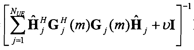
- the total j-MMSE precoder V is computed using the joint transmit and receive MMSE optimization as follows:
- V ( (m + 1) HfG?( W )
- step b) step c) and step d) until
- the Lagrange multiplier ⁇ is obtained as follows.
- step 3 (706)
- step 4) (706)
- step 5) (706)
- step 5) (706)
- step 5) (706)
- ⁇ is the convergent threshold.
- the following noise variance estimation may be used for both non-coherent and coherent precoding.
- the method estimates the UE's noise variance from the reported CQI for the serving TP is as follows:
- the noise variance can be fixed to zero as:
- rank and CQI selection is necessary. From the as many as N TP reported RI in , the majority is selected as the single common RI j for the i -th UE. The selection can be done using the histogram. Then only CQI a (I) associated with the selected RI i are the candidates for CQI selection. The selection is carried out per codeword independently. The majority among the candidates is selected as the common CQI for the / -th codeword CQl i (/) . The selection can be done using the histogram.
- embodiments of the present invention do not require knowledge of the channel to generate the j-MMSE precoder. Rather, they require only the PMI which is fed back by UEs. This may provide a number of advantages. For instance, it may provide improved performance in comparison with methods which directly use reported PMI. Also, as is made evident above, the invention is applicable to both coherent and non-coherent precoding.
Abstract
Description


Claims


Priority Applications (4)
| Application Number | Priority Date | Filing Date | Title |
|---|---|---|---|
| JP2016506015A JP6094718B2 (en) | 2013-08-07 | 2014-08-05 | Generation of a precoder for joint transmission from a plurality of transmission points to a plurality of user equipments in a downlink multipoint coordinated transmission / reception communication system |
| US14/903,065 US9825676B2 (en) | 2013-08-07 | 2014-08-05 | Generating precoders for joint transmission from multiple transmission points to multiple user equipments in a downlink coordinated multipoint transmission/reception communications system |
| EP14835060.6A EP3031237B1 (en) | 2013-08-07 | 2014-08-05 | Generating precoders for joint transmission from multiple transmission points to multiple user equipments in a downlink coordinated multipoint transmission/reception communications system |
| CN201480042428.0A CN105409282B (en) | 2013-08-07 | 2014-08-05 | For generating the method and its system of precoder used in joint transmission |
Applications Claiming Priority (2)
| Application Number | Priority Date | Filing Date | Title |
|---|---|---|---|
| AU2013902955 | 2013-08-07 | ||
| AU2013902955A AU2013902955A0 (en) | 2013-08-07 | Generating precoders for joint transmission from multiple transmission points to multiple user equipments in a downlink coordinated multipoint transmission/reception communications system |
Publications (1)
| Publication Number | Publication Date |
|---|---|
| WO2015020232A1 true WO2015020232A1 (en) | 2015-02-12 |
Family
ID=52461551
Family Applications (1)
| Application Number | Title | Priority Date | Filing Date |
|---|---|---|---|
| PCT/JP2014/071349 WO2015020232A1 (en) | 2013-08-07 | 2014-08-05 | Generating precoders for joint transmission from multiple transmission points to multiple user equipments in a downlink coordinated multipoint transmission/reception communications system |
Country Status (5)
| Country | Link |
|---|---|
| US (1) | US9825676B2 (en) |
| EP (1) | EP3031237B1 (en) |
| JP (1) | JP6094718B2 (en) |
| CN (1) | CN105409282B (en) |
| WO (1) | WO2015020232A1 (en) |
Families Citing this family (2)
| Publication number | Priority date | Publication date | Assignee | Title |
|---|---|---|---|---|
| WO2022209213A1 (en) * | 2021-03-30 | 2022-10-06 | ソニーグループ株式会社 | Wireless communication device and method |
| WO2023145002A1 (en) * | 2022-01-28 | 2023-08-03 | 株式会社Nttドコモ | Terminal, wireless communication method, and base station |
Citations (7)
| Publication number | Priority date | Publication date | Assignee | Title |
|---|---|---|---|---|
| US20110103287A1 (en) | 2009-11-02 | 2011-05-05 | Futurewei Technologies, Inc. | System and Method for Unified Feedback in a Communication System |
| WO2011158302A1 (en) * | 2010-06-18 | 2011-12-22 | Nec Corporation | Precoding techniques for downlink coordinated multipoint transmission in radio communications system |
| WO2012094608A2 (en) * | 2011-01-07 | 2012-07-12 | Interdigital Patent Holdings, Inc. | Communicating channel state information (csi) of multiple transmission points |
| US20120287799A1 (en) * | 2011-05-09 | 2012-11-15 | Texas Instruments Incorporated | Channel feedback for coordinated multi-point transmissions |
| US20130021925A1 (en) | 2011-07-22 | 2013-01-24 | Sharp Laboratories Of America, Inc. | Coordinated multipoint (comp) transmission method selection and feedback requirements |
| US20130083681A1 (en) * | 2011-09-30 | 2013-04-04 | Research In Motion Limited | Methods of Channel State Information Feedback and Transmission in Coordinated Multi-Point Wireless Communications System |
| WO2013112829A1 (en) * | 2012-01-27 | 2013-08-01 | Nec Laboratories America, Inc. | Coordinated multiple point transmission and reception |
Family Cites Families (10)
| Publication number | Priority date | Publication date | Assignee | Title |
|---|---|---|---|---|
| US8406171B2 (en) * | 2008-08-01 | 2013-03-26 | Texas Instruments Incorporated | Network MIMO reporting, control signaling and transmission |
| CN101729131B (en) | 2008-11-03 | 2014-06-04 | 夏普株式会社 | Wireless communication system and pre-coding method |
| CN102396162B (en) | 2009-06-23 | 2016-01-06 | 上海贝尔股份有限公司 | Channel state information feedback method and equipment thereof |
| KR101568291B1 (en) * | 2009-07-10 | 2015-11-20 | 삼성전자주식회사 | Terminal device and base station and operating method of the terminal device |
| WO2011023216A1 (en) * | 2009-08-24 | 2011-03-03 | Nokia Siemens Networks Oy | Channel-adaptive transmission in a distributed coordinated multi-point transmission system |
| JP5268983B2 (en) * | 2010-04-05 | 2013-08-21 | 株式会社エヌ・ティ・ティ・ドコモ | COMMUNICATION CONTROL METHOD, MOBILE STATION DEVICE, AND BASE STATION DEVICE |
| JP5296004B2 (en) * | 2010-04-23 | 2013-09-25 | 株式会社エヌ・ティ・ティ・ドコモ | Feedback information transmission method, mobile station apparatus and base station apparatus |
| CN103918195A (en) * | 2011-11-07 | 2014-07-09 | 摩托罗拉移动有限责任公司 | Method and apparatus for CSI feedback for joint processing schemes in an orthogonal frequency division multiplexing communication system with coordinated multi-point transmission |
| US9214996B2 (en) * | 2012-07-06 | 2015-12-15 | Lg Electronics Inc. | Method of receiving or transmitting downlink signal in wireless communication system and device for performing the method |
| US9698887B2 (en) * | 2013-03-08 | 2017-07-04 | Qualcomm Incorporated | Systems and methods for enhanced MIMO operation |
-
2014
- 2014-08-05 JP JP2016506015A patent/JP6094718B2/en active Active
- 2014-08-05 CN CN201480042428.0A patent/CN105409282B/en active Active
- 2014-08-05 EP EP14835060.6A patent/EP3031237B1/en active Active
- 2014-08-05 US US14/903,065 patent/US9825676B2/en active Active
- 2014-08-05 WO PCT/JP2014/071349 patent/WO2015020232A1/en active Application Filing
Patent Citations (8)
| Publication number | Priority date | Publication date | Assignee | Title |
|---|---|---|---|---|
| US20110103287A1 (en) | 2009-11-02 | 2011-05-05 | Futurewei Technologies, Inc. | System and Method for Unified Feedback in a Communication System |
| WO2011158302A1 (en) * | 2010-06-18 | 2011-12-22 | Nec Corporation | Precoding techniques for downlink coordinated multipoint transmission in radio communications system |
| US20130089159A1 (en) | 2010-06-18 | 2013-04-11 | Nec Corporation | Precoding techniques for downlink coordinated multipoint transmission in radio communications system |
| WO2012094608A2 (en) * | 2011-01-07 | 2012-07-12 | Interdigital Patent Holdings, Inc. | Communicating channel state information (csi) of multiple transmission points |
| US20120287799A1 (en) * | 2011-05-09 | 2012-11-15 | Texas Instruments Incorporated | Channel feedback for coordinated multi-point transmissions |
| US20130021925A1 (en) | 2011-07-22 | 2013-01-24 | Sharp Laboratories Of America, Inc. | Coordinated multipoint (comp) transmission method selection and feedback requirements |
| US20130083681A1 (en) * | 2011-09-30 | 2013-04-04 | Research In Motion Limited | Methods of Channel State Information Feedback and Transmission in Coordinated Multi-Point Wireless Communications System |
| WO2013112829A1 (en) * | 2012-01-27 | 2013-08-01 | Nec Laboratories America, Inc. | Coordinated multiple point transmission and reception |
Non-Patent Citations (1)
| Title |
|---|
| NTT DOCOMO: "Investigation of Aggregated CQI Feedback in Rel-11 CoMP", 3GPP TSG-RAN WG1 MEETING#69 RL-121933, 25 May 2012 (2012-05-25), XP050600234 * |
Also Published As
| Publication number | Publication date |
|---|---|
| EP3031237A4 (en) | 2017-03-15 |
| CN105409282B (en) | 2019-01-22 |
| JP2016532325A (en) | 2016-10-13 |
| CN105409282A (en) | 2016-03-16 |
| EP3031237A1 (en) | 2016-06-15 |
| JP6094718B2 (en) | 2017-03-15 |
| US20160164578A1 (en) | 2016-06-09 |
| US9825676B2 (en) | 2017-11-21 |
| EP3031237B1 (en) | 2019-06-05 |
Similar Documents
| Publication | Publication Date | Title |
|---|---|---|
| CN102725967B (en) | For the method and apparatus of information feed back and precoding | |
| US20130094548A1 (en) | Method for transmitting channel information, device thereof, base station, and method for transmitting for base station thereof | |
| EP2187533A1 (en) | Multi-user precoding and scheduling method and base station for implementing the method | |
| WO2011122919A2 (en) | User equipment apparatus and method for feeding back channel state information in a wireless communication system | |
| EP3565133B1 (en) | Method for feeding back channel state information, terminal device, and network device | |
| US9344160B2 (en) | Data transmission method and system, transmitter, and receiver | |
| JP2015513257A5 (en) | ||
| WO2016169235A1 (en) | Method and apparatus for determining quantity of channel quality indicators (cqi) | |
| US8472381B1 (en) | Methods and apparatus for antenna spoofing | |
| JP2012531132A (en) | Method and related apparatus for transmitting signals in a time division multiple access MIMO system | |
| WO2016098369A1 (en) | Method and system for mimo communication | |
| JP6509255B2 (en) | Multi-antenna data transmission method, base station, user equipment and system | |
| EP2856677B1 (en) | Generating precoders for use in optimising transmission capacity between an enodeb and ue in a dl mu-mimo communications system | |
| JP2014534651A (en) | CSI measurement method and user equipment for CSI measurement in MIMO communication system | |
| WO2017124827A1 (en) | Multiple-antenna data transmission method, network device, terminal device, and system | |
| EP2898721B1 (en) | Method for improving transmission capacity in a dl mu-mimo communications system | |
| WO2015196974A1 (en) | Transmission weighting method and device for csi feedback system | |
| WO2011118962A2 (en) | Apparatus and method for generating codebook in a wireless communication system | |
| WO2015090021A1 (en) | Beam quality information feedback method and system | |
| CN106452544B (en) | Wireless communication method, base station and terminal | |
| WO2017101586A1 (en) | System and method for quantization of angles for beamforming feedback | |
| EP3242454B1 (en) | Method and apparatus for acquiring downlink channel information and network side device | |
| WO2015020232A1 (en) | Generating precoders for joint transmission from multiple transmission points to multiple user equipments in a downlink coordinated multipoint transmission/reception communications system | |
| EP3567771B1 (en) | Method for transmitting channel state information, access network device, and terminal device | |
| WO2016145952A1 (en) | Processing method and apparatus for channel state measurement pilot frequency |
Legal Events
| Date | Code | Title | Description |
|---|---|---|---|
| WWE | Wipo information: entry into national phase |
Ref document number: 201480042428.0 Country of ref document: CN |
|
| 121 | Ep: the epo has been informed by wipo that ep was designated in this application |
Ref document number: 14835060 Country of ref document: EP Kind code of ref document: A1 |
|
| WWE | Wipo information: entry into national phase |
Ref document number: 14903065 Country of ref document: US |
|
| ENP | Entry into the national phase |
Ref document number: 2016506015 Country of ref document: JP Kind code of ref document: A |
|
| NENP | Non-entry into the national phase |
Ref country code: DE |
|
| WWE | Wipo information: entry into national phase |
Ref document number: 2014835060 Country of ref document: EP |