EP3030935B1 - Methods for analyzing thermal image data using a plurality of virtual devices and methods for correlating depth values to image pixels - Google Patents
Methods for analyzing thermal image data using a plurality of virtual devices and methods for correlating depth values to image pixels Download PDFInfo
- Publication number
- EP3030935B1 EP3030935B1 EP14835456.6A EP14835456A EP3030935B1 EP 3030935 B1 EP3030935 B1 EP 3030935B1 EP 14835456 A EP14835456 A EP 14835456A EP 3030935 B1 EP3030935 B1 EP 3030935B1
- Authority
- EP
- European Patent Office
- Prior art keywords
- thermal imaging
- imaging camera
- camera
- images
- image
- Prior art date
- Legal status (The legal status is an assumption and is not a legal conclusion. Google has not performed a legal analysis and makes no representation as to the accuracy of the status listed.)
- Active
Links
- 238000000034 method Methods 0.000 title claims description 21
- 238000001931 thermography Methods 0.000 claims description 66
- 230000000717 retained effect Effects 0.000 claims description 17
- 238000012545 processing Methods 0.000 claims description 9
- 230000007246 mechanism Effects 0.000 claims description 7
- 230000008569 process Effects 0.000 claims description 7
- 238000004458 analytical method Methods 0.000 claims description 6
- 230000008859 change Effects 0.000 claims description 4
- 230000007958 sleep Effects 0.000 claims description 4
- 230000000875 corresponding effect Effects 0.000 description 11
- 230000005540 biological transmission Effects 0.000 description 8
- 238000001514 detection method Methods 0.000 description 6
- 230000008901 benefit Effects 0.000 description 5
- 238000004364 calculation method Methods 0.000 description 4
- 238000004590 computer program Methods 0.000 description 3
- 230000002596 correlated effect Effects 0.000 description 3
- 230000006870 function Effects 0.000 description 3
- 230000003287 optical effect Effects 0.000 description 3
- 238000004891 communication Methods 0.000 description 2
- 238000001228 spectrum Methods 0.000 description 2
- 238000012546 transfer Methods 0.000 description 2
- 241000251468 Actinopterygii Species 0.000 description 1
- 101000822695 Clostridium perfringens (strain 13 / Type A) Small, acid-soluble spore protein C1 Proteins 0.000 description 1
- 101000655262 Clostridium perfringens (strain 13 / Type A) Small, acid-soluble spore protein C2 Proteins 0.000 description 1
- 101000655256 Paraclostridium bifermentans Small, acid-soluble spore protein alpha Proteins 0.000 description 1
- 101000655264 Paraclostridium bifermentans Small, acid-soluble spore protein beta Proteins 0.000 description 1
- 238000003491 array Methods 0.000 description 1
- 230000001413 cellular effect Effects 0.000 description 1
- 239000000470 constituent Substances 0.000 description 1
- 238000012937 correction Methods 0.000 description 1
- 238000013461 design Methods 0.000 description 1
- 238000010586 diagram Methods 0.000 description 1
- 238000005516 engineering process Methods 0.000 description 1
- 230000000873 masking effect Effects 0.000 description 1
- 230000005055 memory storage Effects 0.000 description 1
- 230000004297 night vision Effects 0.000 description 1
- 230000008520 organization Effects 0.000 description 1
- 229920001690 polydopamine Polymers 0.000 description 1
- 230000002250 progressing effect Effects 0.000 description 1
- 230000004044 response Effects 0.000 description 1
- 239000007787 solid Substances 0.000 description 1
- 238000009987 spinning Methods 0.000 description 1
- 238000013403 standard screening design Methods 0.000 description 1
- 238000012876 topography Methods 0.000 description 1
- 238000001429 visible spectrum Methods 0.000 description 1
Images


Classifications
-
- B—PERFORMING OPERATIONS; TRANSPORTING
- B24—GRINDING; POLISHING
- B24B—MACHINES, DEVICES, OR PROCESSES FOR GRINDING OR POLISHING; DRESSING OR CONDITIONING OF ABRADING SURFACES; FEEDING OF GRINDING, POLISHING, OR LAPPING AGENTS
- B24B9/00—Machines or devices designed for grinding edges or bevels on work or for removing burrs; Accessories therefor
- B24B9/02—Machines or devices designed for grinding edges or bevels on work or for removing burrs; Accessories therefor characterised by a special design with respect to properties of materials specific to articles to be ground
- B24B9/06—Machines or devices designed for grinding edges or bevels on work or for removing burrs; Accessories therefor characterised by a special design with respect to properties of materials specific to articles to be ground of non-metallic inorganic material, e.g. stone, ceramics, porcelain
- B24B9/08—Machines or devices designed for grinding edges or bevels on work or for removing burrs; Accessories therefor characterised by a special design with respect to properties of materials specific to articles to be ground of non-metallic inorganic material, e.g. stone, ceramics, porcelain of glass
- B24B9/14—Machines or devices designed for grinding edges or bevels on work or for removing burrs; Accessories therefor characterised by a special design with respect to properties of materials specific to articles to be ground of non-metallic inorganic material, e.g. stone, ceramics, porcelain of glass of optical work, e.g. lenses, prisms
-
- G—PHYSICS
- G06—COMPUTING; CALCULATING OR COUNTING
- G06T—IMAGE DATA PROCESSING OR GENERATION, IN GENERAL
- G06T7/00—Image analysis
- G06T7/70—Determining position or orientation of objects or cameras
- G06T7/73—Determining position or orientation of objects or cameras using feature-based methods
- G06T7/74—Determining position or orientation of objects or cameras using feature-based methods involving reference images or patches
-
- B—PERFORMING OPERATIONS; TRANSPORTING
- B29—WORKING OF PLASTICS; WORKING OF SUBSTANCES IN A PLASTIC STATE IN GENERAL
- B29C—SHAPING OR JOINING OF PLASTICS; SHAPING OF MATERIAL IN A PLASTIC STATE, NOT OTHERWISE PROVIDED FOR; AFTER-TREATMENT OF THE SHAPED PRODUCTS, e.g. REPAIRING
- B29C45/00—Injection moulding, i.e. forcing the required volume of moulding material through a nozzle into a closed mould; Apparatus therefor
- B29C45/0053—Injection moulding, i.e. forcing the required volume of moulding material through a nozzle into a closed mould; Apparatus therefor combined with a final operation, e.g. shaping
- B29C45/0055—Shaping
-
- G—PHYSICS
- G02—OPTICS
- G02B—OPTICAL ELEMENTS, SYSTEMS OR APPARATUS
- G02B27/00—Optical systems or apparatus not provided for by any of the groups G02B1/00 - G02B26/00, G02B30/00
- G02B27/0006—Optical systems or apparatus not provided for by any of the groups G02B1/00 - G02B26/00, G02B30/00 with means to keep optical surfaces clean, e.g. by preventing or removing dirt, stains, contamination, condensation
-
- G—PHYSICS
- G03—PHOTOGRAPHY; CINEMATOGRAPHY; ANALOGOUS TECHNIQUES USING WAVES OTHER THAN OPTICAL WAVES; ELECTROGRAPHY; HOLOGRAPHY
- G03B—APPARATUS OR ARRANGEMENTS FOR TAKING PHOTOGRAPHS OR FOR PROJECTING OR VIEWING THEM; APPARATUS OR ARRANGEMENTS EMPLOYING ANALOGOUS TECHNIQUES USING WAVES OTHER THAN OPTICAL WAVES; ACCESSORIES THEREFOR
- G03B37/00—Panoramic or wide-screen photography; Photographing extended surfaces, e.g. for surveying; Photographing internal surfaces, e.g. of pipe
- G03B37/02—Panoramic or wide-screen photography; Photographing extended surfaces, e.g. for surveying; Photographing internal surfaces, e.g. of pipe with scanning movement of lens or cameras
-
- G—PHYSICS
- G06—COMPUTING; CALCULATING OR COUNTING
- G06T—IMAGE DATA PROCESSING OR GENERATION, IN GENERAL
- G06T1/00—General purpose image data processing
- G06T1/0007—Image acquisition
-
- G—PHYSICS
- G06—COMPUTING; CALCULATING OR COUNTING
- G06T—IMAGE DATA PROCESSING OR GENERATION, IN GENERAL
- G06T3/00—Geometric image transformation in the plane of the image
- G06T3/40—Scaling the whole image or part thereof
- G06T3/4038—Scaling the whole image or part thereof for image mosaicing, i.e. plane images composed of plane sub-images
-
- G—PHYSICS
- G06—COMPUTING; CALCULATING OR COUNTING
- G06T—IMAGE DATA PROCESSING OR GENERATION, IN GENERAL
- G06T7/00—Image analysis
- G06T7/50—Depth or shape recovery
- G06T7/55—Depth or shape recovery from multiple images
-
- H—ELECTRICITY
- H04—ELECTRIC COMMUNICATION TECHNIQUE
- H04N—PICTORIAL COMMUNICATION, e.g. TELEVISION
- H04N23/00—Cameras or camera modules comprising electronic image sensors; Control thereof
- H04N23/60—Control of cameras or camera modules
-
- H—ELECTRICITY
- H04—ELECTRIC COMMUNICATION TECHNIQUE
- H04N—PICTORIAL COMMUNICATION, e.g. TELEVISION
- H04N23/00—Cameras or camera modules comprising electronic image sensors; Control thereof
- H04N23/60—Control of cameras or camera modules
- H04N23/698—Control of cameras or camera modules for achieving an enlarged field of view, e.g. panoramic image capture
-
- H—ELECTRICITY
- H04—ELECTRIC COMMUNICATION TECHNIQUE
- H04N—PICTORIAL COMMUNICATION, e.g. TELEVISION
- H04N5/00—Details of television systems
- H04N5/30—Transforming light or analogous information into electric information
- H04N5/33—Transforming infrared radiation
-
- B—PERFORMING OPERATIONS; TRANSPORTING
- B29—WORKING OF PLASTICS; WORKING OF SUBSTANCES IN A PLASTIC STATE IN GENERAL
- B29C—SHAPING OR JOINING OF PLASTICS; SHAPING OF MATERIAL IN A PLASTIC STATE, NOT OTHERWISE PROVIDED FOR; AFTER-TREATMENT OF THE SHAPED PRODUCTS, e.g. REPAIRING
- B29C45/00—Injection moulding, i.e. forcing the required volume of moulding material through a nozzle into a closed mould; Apparatus therefor
- B29C45/0053—Injection moulding, i.e. forcing the required volume of moulding material through a nozzle into a closed mould; Apparatus therefor combined with a final operation, e.g. shaping
- B29C45/0055—Shaping
- B29C2045/0058—Shaping removing material
-
- B—PERFORMING OPERATIONS; TRANSPORTING
- B29—WORKING OF PLASTICS; WORKING OF SUBSTANCES IN A PLASTIC STATE IN GENERAL
- B29K—INDEXING SCHEME ASSOCIATED WITH SUBCLASSES B29B, B29C OR B29D, RELATING TO MOULDING MATERIALS OR TO MATERIALS FOR MOULDS, REINFORCEMENTS, FILLERS OR PREFORMED PARTS, e.g. INSERTS
- B29K2023/00—Use of polyalkenes or derivatives thereof as moulding material
- B29K2023/04—Polymers of ethylene
- B29K2023/06—PE, i.e. polyethylene
- B29K2023/0658—PE, i.e. polyethylene characterised by its molecular weight
- B29K2023/0683—UHMWPE, i.e. ultra high molecular weight polyethylene
-
- B—PERFORMING OPERATIONS; TRANSPORTING
- B29—WORKING OF PLASTICS; WORKING OF SUBSTANCES IN A PLASTIC STATE IN GENERAL
- B29K—INDEXING SCHEME ASSOCIATED WITH SUBCLASSES B29B, B29C OR B29D, RELATING TO MOULDING MATERIALS OR TO MATERIALS FOR MOULDS, REINFORCEMENTS, FILLERS OR PREFORMED PARTS, e.g. INSERTS
- B29K2995/00—Properties of moulding materials, reinforcements, fillers, preformed parts or moulds
- B29K2995/0018—Properties of moulding materials, reinforcements, fillers, preformed parts or moulds having particular optical properties, e.g. fluorescent or phosphorescent
- B29K2995/0026—Transparent
-
- B—PERFORMING OPERATIONS; TRANSPORTING
- B29—WORKING OF PLASTICS; WORKING OF SUBSTANCES IN A PLASTIC STATE IN GENERAL
- B29K—INDEXING SCHEME ASSOCIATED WITH SUBCLASSES B29B, B29C OR B29D, RELATING TO MOULDING MATERIALS OR TO MATERIALS FOR MOULDS, REINFORCEMENTS, FILLERS OR PREFORMED PARTS, e.g. INSERTS
- B29K2995/00—Properties of moulding materials, reinforcements, fillers, preformed parts or moulds
- B29K2995/0018—Properties of moulding materials, reinforcements, fillers, preformed parts or moulds having particular optical properties, e.g. fluorescent or phosphorescent
- B29K2995/0029—Translucent
-
- B—PERFORMING OPERATIONS; TRANSPORTING
- B29—WORKING OF PLASTICS; WORKING OF SUBSTANCES IN A PLASTIC STATE IN GENERAL
- B29K—INDEXING SCHEME ASSOCIATED WITH SUBCLASSES B29B, B29C OR B29D, RELATING TO MOULDING MATERIALS OR TO MATERIALS FOR MOULDS, REINFORCEMENTS, FILLERS OR PREFORMED PARTS, e.g. INSERTS
- B29K2995/00—Properties of moulding materials, reinforcements, fillers, preformed parts or moulds
- B29K2995/0037—Other properties
- B29K2995/0094—Geometrical properties
- B29K2995/0097—Thickness
-
- B—PERFORMING OPERATIONS; TRANSPORTING
- B29—WORKING OF PLASTICS; WORKING OF SUBSTANCES IN A PLASTIC STATE IN GENERAL
- B29L—INDEXING SCHEME ASSOCIATED WITH SUBCLASS B29C, RELATING TO PARTICULAR ARTICLES
- B29L2031/00—Other particular articles
- B29L2031/764—Photographic equipment or accessories
-
- G—PHYSICS
- G03—PHOTOGRAPHY; CINEMATOGRAPHY; ANALOGOUS TECHNIQUES USING WAVES OTHER THAN OPTICAL WAVES; ELECTROGRAPHY; HOLOGRAPHY
- G03B—APPARATUS OR ARRANGEMENTS FOR TAKING PHOTOGRAPHS OR FOR PROJECTING OR VIEWING THEM; APPARATUS OR ARRANGEMENTS EMPLOYING ANALOGOUS TECHNIQUES USING WAVES OTHER THAN OPTICAL WAVES; ACCESSORIES THEREFOR
- G03B11/00—Filters or other obturators specially adapted for photographic purposes
- G03B11/04—Hoods or caps for eliminating unwanted light from lenses, viewfinders or focusing aids
- G03B11/041—Lens caps as separate accessory
-
- G—PHYSICS
- G06—COMPUTING; CALCULATING OR COUNTING
- G06T—IMAGE DATA PROCESSING OR GENERATION, IN GENERAL
- G06T2207/00—Indexing scheme for image analysis or image enhancement
- G06T2207/10—Image acquisition modality
- G06T2207/10016—Video; Image sequence
-
- G—PHYSICS
- G06—COMPUTING; CALCULATING OR COUNTING
- G06T—IMAGE DATA PROCESSING OR GENERATION, IN GENERAL
- G06T2207/00—Indexing scheme for image analysis or image enhancement
- G06T2207/10—Image acquisition modality
- G06T2207/10028—Range image; Depth image; 3D point clouds
-
- G—PHYSICS
- G06—COMPUTING; CALCULATING OR COUNTING
- G06T—IMAGE DATA PROCESSING OR GENERATION, IN GENERAL
- G06T2207/00—Indexing scheme for image analysis or image enhancement
- G06T2207/10—Image acquisition modality
- G06T2207/10048—Infrared image
-
- G—PHYSICS
- G06—COMPUTING; CALCULATING OR COUNTING
- G06T—IMAGE DATA PROCESSING OR GENERATION, IN GENERAL
- G06T2207/00—Indexing scheme for image analysis or image enhancement
- G06T2207/30—Subject of image; Context of image processing
- G06T2207/30232—Surveillance
-
- H—ELECTRICITY
- H04—ELECTRIC COMMUNICATION TECHNIQUE
- H04N—PICTORIAL COMMUNICATION, e.g. TELEVISION
- H04N3/00—Scanning details of television systems; Combination thereof with generation of supply voltages
- H04N3/02—Scanning details of television systems; Combination thereof with generation of supply voltages by optical-mechanical means only
- H04N3/04—Scanning details of television systems; Combination thereof with generation of supply voltages by optical-mechanical means only having a moving aperture also apertures covered by lenses
-
- H—ELECTRICITY
- H04—ELECTRIC COMMUNICATION TECHNIQUE
- H04N—PICTORIAL COMMUNICATION, e.g. TELEVISION
- H04N5/00—Details of television systems
- H04N5/222—Studio circuitry; Studio devices; Studio equipment
- H04N5/262—Studio circuits, e.g. for mixing, switching-over, change of character of image, other special effects ; Cameras specially adapted for the electronic generation of special effects
- H04N5/2628—Alteration of picture size, shape, position or orientation, e.g. zooming, rotation, rolling, perspective, translation
Definitions
- Panoramic images can be created by an array of wide angle cameras that together create up to a 360 degree field of view or by one camera with a fish eye lens or other panoramic mirror that allows for a continuous "mirror ball” image that is later flattened out by computer. These images are limited in their ability to provide detail necessary to be useful for video surveillance because the sensors are stretched over wide fields of view (sometimes a full 360 degrees).
- a relatively new means of capturing thermal panoramic images is by continuously spinning a cryogenically cooled thermal sensor or other high-speed camera at less than 60 RPM and processing the images from the camera with a computer where they are stitched together and analyzed.
- cryogenically cooled sensors have the ability to capture images in just a few nanoseconds, which allows them to produce near real time video.
- these cooled sensors are power hungry and expensive, making them impractical in many applications.
- the high-speed cameras have very large lighting requirements making them of very limited use in other than full daylight conditions.
- WO 2012/029063 discloses a rotary system for capturing images, comprising a rotatable camera for capturing a plurality of still images per second, each taken in a various view angles and stored operable to display streams of images from various views on multiple display devices.
- the system may include an infra-red night-vision camera.
- Implementations of the present invention comprise systems, methods and computer program products configured to sort and analyze individual image frames of panoramic image data using a plurality of virtual devices.
- an embodiment of the present invention is directed to an on-site system for analyzing and sorting individual image frames of panoramic image data according to claim 1.
- Implementations of the present invention comprise systems, methods and computer program products configured to sort and analyze individual image frames of panoramic image data using a plurality of virtual devices.
- an embodiment of the present invention comprises a method S10 of obtaining thermal imaging camera images from a thermal imaging camera that rotates through a plurality of stop positions (S12).
- the camera may capture thermal imaging camera images at a constant frame rate. At least some of the thermal imaging camera images correspond to stop positions, while other captured thermal imaging camera images may not correspond to any stop position.
- Thermal imaging camera images corresponding to any of the stop positions are retained (S14), while thermal imaging camera images that do not correspond to any stop position are discarded (S16).
- Retained thermal imaging camera images are sent in a video stream to a video processor (S18). They may be separated into individual thermal imaging camera images, sorted, and stored for a corresponding virtual camera device that corresponds to the specific stop position to which the given image corresponds (S20).
- the on-site system may include appropriate memory for storing the images. Alternatively, some or all of the images may be stored off-site and relayed on-site as needed.
- the virtual camera devices may be on-site relative to the thermal imaging camera.
- the thermal imaging camera images are not stitched together on-site into a panoramic image on-site, so that the total power requirements of the on-site system (e.g., including the thermal imaging camera, an indexing mechanism for rotating the camera, and a multiplexing and analysis module for sorting images for the virtual camera devices) are no more than about 10 watts (S22).
- the on-site system e.g., including the thermal imaging camera, an indexing mechanism for rotating the camera, and a multiplexing and analysis module for sorting images for the virtual camera devices
- the individual thermal imaging camera images from each stop position may be analyzed as a video stream to detect a change from a given image to a subsequent image (S24).
- Discarding images that do not correspond to any stop position may allow the video processor to periodically sleep because it never receives those images, thus making the system more power efficient.
- on-site analytics are limited to relatively simple functions (e.g., not stitching images together, etc.)
- the system exhibits relatively limited power consumption characteristics (e.g., less than about 10 watts, can be left unattended for a period of years and can be powered by batteries charged by relatively small solar cells).
- a method for correlating geographical location data including determination of depth values for pixel positions of an individual image frame of a panoramic image.
- the method may comprise the steps of obtaining camera images (e.g., thermal imaging camera images) from a single camera that rotates through a plurality of stop positions (S32).
- the camera may capture images at a constant frame rate, at least some of the images corresponding to stop positions as the camera rotates through the plurality of stop positions.
- a position of the camera may be correlated with geographical location data (S34), pixel positions of a given camera image may be correlated with geographical location data (S36), and depth values for pixel positions of the given camera image may be determined based at least in part on the geographical location of the camera and the orientation or position in which the given stop position is "pointed" (S38).
- depth information determinations may be performed off-site, and relayed back to the camera system site for storage on-site (S40).
- the analytics and processing that correlates positions of an image with location data, determining the appropriate depth value for each pixel may be performed off-site, and the results may be relayed to the on-site system for use by the camera system, further reducing power requirements of the on-site system.
- a given depth value for a pixel position of a given thermal imaging camera image may be compared to a previously or subsequently obtained thermal imaging camera image from the same stop position to determine any changes, e.g., the size or movement speed of an object shown in the thermal imaging camera images (S42).
- Computing systems are now increasingly taking a wide variety of forms. Computing systems may, for example, be handheld devices, appliances, laptop computers, desktop computers, mainframes, distributed computing systems, or even devices that have not conventionally been considered a computing system.
- computing system is defined broadly as including any device or system (or combination thereof) that includes at least one physical and tangible processor, and a physical and tangible memory capable of having thereon computer-executable instructions that may be executed by the
- Figure 1 illustrates an exemplary computing system 100.
- a computing system 100 typically includes at least one processing unit 102 and memory 104.
- the memory 104 may be physical system memory, which may be volatile, non-volatile, or some combination of the two.
- the term "memory" may also be used herein to refer to non-volatile mass storage such as physical storage media. If the computing system is distributed, the processing, memory and/or storage capability may be distributed as well.
- Each of the computer systems described herein may be connected to one another over (or may be part of) a network, such as, for example, a Local Area Network ("LAN”), a Wide Area Network (“WAN”), and even the Internet. Accordingly, each of the described computer systems as well as any other connected computer systems and their components, can create message related data and exchange message related data (e.g., Internet Protocol (“IP”) datagrams and other higher layer protocols that utilize IP datagrams, such as, Transmission Control Protocol (“TCP”), Hypertext Transfer Protocol (“HTTP”), Simple Mail Transfer Protocol (“SMTP”), etc.) over the network.
- IP Internet Protocol
- TCP Transmission Control Protocol
- HTTP Hypertext Transfer Protocol
- SMTP Simple Mail Transfer Protocol
- executable module can refer to software objects, routings, or methods that may be executed on the computing system.
- the different components, modules, engines, and services described herein may be implemented as objects or processes that execute on the computing system (e.g., as separate threads).
- embodiments are described with reference to acts that are performed by one or more computing systems. If such acts are implemented in software, one or more processors of the associated computing system that performs the act direct the operation of the computing system in response to having executed computer-executable instructions.
- such computer-executable instructions may be embodied on one or more computer-readable media that form a computer program product.
- An example of such an operation involves the manipulation of data.
- the computer-executable instructions (and the manipulated data) may be stored in the memory 104 of the computing system 100.
- Computing system 100 may also contain communication channels 108 that allow the computing system 100 to communicate with other message processors over, for example, network 110.
- Embodiments described herein may comprise or utilize a special-purpose or general-purpose computer system that includes computer hardware, such as, for example, one or more processors and system memory, as discussed in greater detail below.
- the system memory may be included within the overall memory 104.
- the system memory may also be referred to as "main memory", and includes memory locations that are addressable by the at least one processing unit 102 over a memory bus in which case the address location is asserted on the memory bus itself.
- System memory has traditionally been volatile, but the principles described herein also apply in circumstances in which the system memory is partially, or even fully, non-volatile.
- Embodiments within the scope of the present invention also include physical and other computer-readable media for carrying or storing computer-executable instructions and/or data structures.
- Such computer-readable media can be any available media that can be accessed by a general-purpose or special-purpose computer system.
- Computer-readable media that store computer-executable instructions and/or data structures are computer storage media.
- Computer-readable media that carry computer-executable instructions and/or data structures are transmission media.
- embodiments of the invention can comprise at least two distinctly different kinds of computer-readable media: computer storage media and transmission media.
- Computer storage media are physical storage media that store computer-executable instructions and/or data structures.
- Physical storage media includes recordable-type storage devices, such as RAM, ROM, EEPROM, solid state drives (“SSDs”), flash memory, phase-change memory (“PCM”), optical disk storage, magnetic disk storage or other magnetic storage devices, or any other physical hardware storage medium(s) which can be used to store program code in the form of computer-executable instructions or data structures, and which can be accessed and executed by a general-purpose or special-purpose computer system to implement the functionality described herein.
- recordable-type storage devices such as RAM, ROM, EEPROM, solid state drives (“SSDs”), flash memory, phase-change memory (“PCM”), optical disk storage, magnetic disk storage or other magnetic storage devices, or any other physical hardware storage medium(s) which can be used to store program code in the form of computer-executable instructions or data structures, and which can be accessed and executed by a general-purpose or special-purpose computer system to implement the functionality described herein.
- Transmission media can include a network and/or data links which can be used to carry program code in the form of computer-executable instructions or data structures, and which can be accessed by a general-purpose or special-purpose computer system.
- a "network" is defined as one or more data links that enable the transport of electronic data between computer systems and/or modules and/or other electronic devices.
- program code in the form of computer-executable instructions or data structures can be transferred automatically from transmission media to computer storage media (or vice versa).
- program code in the form of computer-executable instructions or data structures received over a network or data link can be buffered in RAM within a network interface module (e.g., a "NIC"), and then eventually transferred to computer system RAM and/or to less volatile computer storage media at a computer system.
- a network interface module e.g., a "NIC”
- computer storage media can be included in computer system components that also (or even primarily) utilize transmission media.
- Computer-executable instructions comprise, for example, instructions and data which, when executed at one or more processors, cause a general-purpose computer system, special-purpose computer system, or special-purpose processing device to perform a certain function or group of functions.
- Computer-executable instructions may be, for example, binaries, intermediate format instructions such as assembly language, or even source code.
- the invention may be practiced in network computing environments with many types of computer system configurations, including, personal computers, desktop computers, laptop computers, message processors, hand-held devices, multi-processor systems, microprocessor-based or programmable consumer electronics, network PCs, minicomputers, mainframe computers, mobile telephones, PDAs, tablets, pagers, routers, switches, and the like.
- the invention may also be practiced in distributed system environments where local and remote computer systems, which are linked (either by hardwired data links, wireless data links, or by a combination of hardwired and wireless data links) through a network, both perform tasks.
- a computer system may include a plurality of constituent computer systems.
- program modules may be located in both local and remote memory storage devices.
- Cloud computing environments may be distributed, although this is not required. When distributed, cloud computing environments may be distributed internationally within an organization and/or have components possessed across multiple organizations.
- cloud computing is defined as a model for enabling on-demand network access to a shared pool of configurable computing resources (e.g., networks, servers, storage, applications, and services). The definition of “cloud computing” is not limited to any of the other numerous advantages that can be obtained from such a model when properly deployed.
- the functionally described herein can be performed, at least in part, by one or more hardware logic components.
- illustrative types of hardware logic components include Field-programmable Gate Arrays (FPGAs), Program-specific Integrated Circuits (ASICs), Program-specific Standard Products (ASSPs), System-on-a-chip systems (SOCs), Complex Programmable Logic Devices (CPLDs), etc.
- FIG. 2 illustrates a block diagram for camera system 200.
- Camera system 200 allows camera 250 (e.g., a thermal imaging camera) to rotate up to a full 360° around a fixed-axis. The full revolution comprises a number of positions corresponding to "stops" where it is desired that an image be captured. Because of requirements related to camera calibration, particularly with a thermal imaging camera, the camera can capture images at a constant frame rate.
- the spectrum captured may be from about 800 nm to about 1400 nm.
- some of the images may correspond to positions between designated “stop” positions, while others will correspond to a "stop” position. As will be described in further detail hereafter, only those images corresponding to a "stop” position may be retained. The others may be discarded.
- a stop position can be characterized as having an angle offset relative to a designated home position (i.e., "stop" 1) at which camera 250 captures an image.
- the system may determine the home position by using a camera-mount with a hole, along with a transmissive optical encoder that can detect the home position when the hole in the camera-mount lines up with the encoder.
- a transmissive optical encoder may be a 1-bit encoder.
- a higher resolution encoder may be used to allow more granular feedback of actual camera position at any given time.
- Camera system 200 can allow any number of stop positions per revolution.
- the number of stop positions may be between 1 and 16.
- the stops may be positioned at equally spaced intervals. For example, ten stop positions, or stops, per revolution would result in ten stops that are located 36° apart.
- the camera system 200 may use any suitable motor mechanism for ensuring that the camera remains momentarily stationary at each stop position, so as to facilitate capture of a non-blurry image at each desired stop position.
- a stepper motor may be employed to hold camera 250 stationary at each stop position for the appropriate amount of time to acquire an image before moving to the next stop position. Details of an exemplary stepper motor mechanism are disclosed in the inventors PCT Patent Application Serial No.
- Another example of a motor mechanism that may be employed in rotating the camera through a plurality of stop positions in which the camera remains stationary momentarily at each stop position includes a mechanical cam system, e.g., as described in the inventors U.S. Patent No. 8,773,503 issued July 8, 2014 and titled AUTOMATED PANORAMIC CAMERA AND SENSOR PLATFORM WITH COMPUTER AND OPTIONAL POWER SUPPLY.
- Motor mechanisms as described in the above patents and applications, as well as any other suitable design may be employed.
- the system can utilize two processors, microprocessor 210 and video processor 240.
- Microprocessor 210 can manage position and timing of camera 250, while video processor 240 can process video from camera 250.
- Utilizing two processors allows the real-time performance of the camera 250 and motor synchronization by the microprocessor 210 to be de-coupled from the high-throughput video processor 240.
- some implementations may use one processor to manage position and timing, as well as video of the camera 250. Of course, more than two processors could alternatively be employed.
- data from the camera 250 passes through slip rings 260, which allows the camera 250 to rotate as described above (continuous rotation with intermittent, very short stops). Because the periods where the camera is actually stationary are so short, the camera may appear to rotate continuously. In some cases, the camera frame rate may not exactly match the rotational speed and stop rate of the camera system 200, thus creating fractional video frames.
- Digital switch 230 may then be used to throw away any unwanted video frames. In other words, as described above, some captured frames may correspond to one of the stop positions, while other captured frames may be captured while the camera is rotating. Using the digital switch 230 allows the video processor 240 to sleep during those times at which unwanted video frames are discarded, thus creating better power efficiency.
- the video processor e.g., ARM/DSP
- the video processor may have little or no time to sleep.
- each stop position can be represented as an individual virtual camera.
- a virtual camera may act like a stationary camera pointed in a single direction.
- the camera system 200 can support any number of stop positions and corresponding number of virtual cameras.
- system 200 may include from 1 to 16 stop positions, and 1 to 16 virtual cameras, each virtual camera associated with a particular stop position.
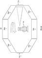
- Figure 3A illustrates how each stop position may correlate to a physical space with the camera 250 facing stop position 1 (i.e., home position).
- Figure 3B shows the camera 250 having rotated so as to be facing stop position 5.
- a numbering system used for the stop positions may increase in a clockwise direction.
- Figures 3A and 3B illustrate an exemplary configuration including 8 stop positions, although it will be understood that more or fewer stop positions may be provided.
- the number of stop positions may be from 2 to about 30, from 4 to about 20, or from 6 to about 16.
- each stop period i.e., the dwell time
- each stop period may be from about 30 ms to about 120 ms (e.g., about 60 ms).
- Each image captured by camera 250 corresponding to a stop position may be multiplexed, or muxed, into a video stream and sent to video processor 240.
- Each image captured by camera 250 to be retained may be sent out of the camera over the same interface.
- Microprocessor 210 can manage and track the angle offset (and corresponding stop position) of camera 250 when an image to be retained is captured (i.e., the image corresponds to a stop position). Even images that are to be discarded (i.e., the image does not correspond to a stop position), may be sent to digital switch 230 over the same interface as retained images. At digital switch 230, those images that are to be discarded may be separated and discarded, rather than passed on to video processor 240.
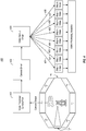
- video demultiplexing driver 430 separates the video stream into individual images (i.e., frames) that each correspond to a particular stop position, or virtual camera.
- the video stream referred to at this stage may include images to be retained that were captured at different stop positions.
- Demulitplexing driver 430 may use position information tracked by microprocessor 210 to determine the corresponding virtual camera for each image of the video stream, allowing sorting of the images to their proper virtual camera devices.
- each image can be sent to its corresponding virtual camera (401 - 408) for storage and future analytics (e.g., comparison of images taken adjacent in time from the same stop position), once that determination has been made.
- images from different stop positions may be stitched together to create a panoramic image (e.g., of up to 360°).
- An advantage of the present embodiments is that any such stitching is optional, and is typically not carried out on-site (if at all). If done, stitching may be done off-site, allowing the total power requirements for on-site system 200 to be no more than about 10 watts, as stitching is power and computer processor intensive.
- the video stream associated with a given virtual camera device may be analyzed to detect a change from a given image to a subsequent image.
- the analytics carried out may involve comparison of an image with a subsequently captured image (or a previously captured image) from the same stop position (and thus the same virtual camera device) to detect any changes (e.g., a change in temperature of an object, movement of an object, etc.).
- the analytics carried out may include fire detection, as discussed in the inventors' prior PCT Patent Application Serial No. PCT/US/2014/033539 filed April 9, 2014 titled STEPPER MOTOR CONTROL AND FIRE DETECTION SYSTEM, and PCT Patent Application Serial No. PCT/US/2014/033547 filed April 9, 2014 titled FIRE DETECTION SYSTEM.
- background masking can be simplified as compared to visible spectrum data, simplifying object identification.
- Power may be supplied to the on-site system using batteries that are charged via solar cells, which can allow the system to be placed in a given location (e.g., remote, off the power grid) for long periods of time, such as up to two years or more. Lifespan may be shorter or longer than 2 years, depending on the system characteristics.
- Each virtual camera can have a video stream similar to that which would be obtained by a stationary camera placed at the corresponding stop position.
- the system of virtual cameras may be on-site relative to thermal imaging camera 250.
- the frame rate of a virtual camera video stream is equal to the rotational speed of motor 270, as camera 250 passes each stop once per revolution.
- the muxed signal frame rate may be equal to a rotational speed of motor 270 multiplied by the number of stops per revolution.
- FPS frames per second
- Utilizing virtual cameras can allow analytics and any stitching to be decoupled from image acquisition. Because each virtual camera can have its own video stream, images associated with each virtual camera can be processed independently. System 200 may normally capture images in numerical (e.g., clockwise or counter-clockwise) order, but because the angle offset from home position (i.e., stop position 1) is known based on the stop number of the virtual camera, analytics or any stitching may update in any order desired.
- the position of camera 250 at which an image is captured can be correlated with actual geographical location data (e.g., GPS data). Once it is known where the actual camera 250 is located, based on geographical location data, the camera can be located on a 3D topography map. Similarly, depth values for individual pixels of a given frame of a given virtual camera device (i.e., stop position) may be determined. Corrections may be made for tilt and height.
- actual geographical location data e.g., GPS data
- Correlating geographical location data with the position of camera 250 can include, but is not limited to, correlating pixel positions of a captured image and determining depth values for pixel positions of individual thermal imaging camera images based on the geographical location of thermal imaging camera 250. Given the elevation and orientation of thermal imaging camera 250, the distance or depth value for each pixel of an image may be calculated using elevation data, for example, from the National Elevation Dataset.
- the depth value calculation to be associated with a given pixel can be done in a series of steps for determining (e.g., calculating) how each pixel represents a ray projected from the camera across the landscape intersecting the ground. Generally, this may be achieved by using a projected camera view on a wireframe terrain model created using elevation data (e.g., from the National Elevation Dataset) to estimate where each rendered pixel of the camera view would intersect the wireframe to calculate the probable "z" depth value of the bottom of each image element or pixel. Such a process may employ a loop process carried out through increasing z-distances until the projected height intersects the elevation height at a distance.
- elevation data e.g., from the National Elevation Dataset
- This may be done by determining (e.g., calculating) if a ray having a length equal to the camera's height intersects the ground at the projected distance. This determination may be repeated by repeatedly increasing the ray length by a given amount (e.g., 1 decimeter) until the ground is reached (e.g., intersected) or the ray exceeds a given length (e.g., 30 kilometers). Such an excessive length may be used to help render the horizon. Data for latitude, longitude, elevation and distance of the intersection point may be stored, and the determination (e.g., calculation) may be repeated for the next pixel of a column.
- a given amount e.g. 1 decimeter
- the determination may move onto a new column. Such determinations or calculations may be based off variable Vertical Field of View, Horizontal Field of View, elevation and orientation.
- the final data set may be used to render an image that depicts distance (e.g., in gray scale) with lines placed at a given distance (e.g., every 100 meters).
- the determined or calculated image may be compared against an actual image for a final adjustment of the input variables. Once completed, the final result would provide a "z" depth value map that can be saved for future immediate analytics availability.
- an image of 640x512 may require repetition of the described determinations approximately 250,000 times.
- depth values for pixel positions may allow determination of the size or movement speed of an object captured within an image. For example, it may provide information on the size or movement speed of a wildfire.
- Processing that correlates pixel positions of an image with location data and determination of a depth value associated with each pixel may be performed off-site at a remote user interface terminal. The actual depth values associated with given pixels of the images may be relayed to the camera system for storage and use on-site.
- Relay of any data on-site to off-site or vice versa may be by any suitable mechanism, e.g., including, but not limited to satellite link or network, cellular link or network, WiFi link or network, radio transmission, hard wired link or network, etc.
Description
- Panoramic images can be created by an array of wide angle cameras that together create up to a 360 degree field of view or by one camera with a fish eye lens or other panoramic mirror that allows for a continuous "mirror ball" image that is later flattened out by computer. These images are limited in their ability to provide detail necessary to be useful for video surveillance because the sensors are stretched over wide fields of view (sometimes a full 360 degrees).
- A relatively new means of capturing thermal panoramic images is by continuously spinning a cryogenically cooled thermal sensor or other high-speed camera at less than 60 RPM and processing the images from the camera with a computer where they are stitched together and analyzed. These cryogenically cooled sensors have the ability to capture images in just a few nanoseconds, which allows them to produce near real time video. However, these cooled sensors are power hungry and expensive, making them impractical in many applications. In addition, the high-speed cameras have very large lighting requirements making them of very limited use in other than full daylight conditions.
- Even with existing advancements in the art, there still exists a need for improved camera systems and analysis methods, particularly for those which exhibit minimal complexity and cost, and which can operate under relatively low power requirements.
-
WO 2012/029063 discloses a rotary system for capturing images, comprising a rotatable camera for capturing a plurality of still images per second, each taken in a various view angles and stored operable to display streams of images from various views on multiple display devices. The system may include an infra-red night-vision camera. - The subject matter claimed herein is not limited to embodiments that solve any disadvantages or that operate only in environments such as those described above. Rather, this background is only provided to illustrate one exemplary technology area where some embodiments described herein may be practiced.
- Implementations of the present invention comprise systems, methods and computer program products configured to sort and analyze individual image frames of panoramic image data using a plurality of virtual devices. For example, an embodiment of the present invention is directed to an on-site system for analyzing and sorting individual image frames of panoramic image data according to
claim 1. - Additional features and advantages will be set forth in the description which follows, and in part will be obvious from the description, or may be learned by the practice of the teachings herein. Features and advantages of the invention may be realized and obtained by means of the instruments and combinations particularly pointed out in the appended claims. Features of the present invention will become more fully apparent from the following description and appended claims, or may be learned by the practice of the invention as set forth hereinafter.
- In order to describe the manner in which the above-recited and other advantages and features can be obtained, a more particular description of the subject matter briefly described above will be rendered by reference to specific embodiments which are illustrated in the appended drawings. Understanding that these drawings depict only typical embodiments and are not therefore to be considered to be limiting in scope, embodiments will be described and explained with additional specificity and detail through the use of the accompanying drawings in which:
-
Figure 1 schematically illustrates an example computing system in which the principles described herein may operate. -
Figure 2 schematically illustrates a specific environment in which the principles described herein may operate. -
Figure 3A schematically illustrates virtual camera positions, also referred to herein as stop positions, when rotating in a clockwise direction, with the camera pointed atstop position 1. -
Figure 3B schematically illustrates virtual camera positions, as inFigure 3A , with the camera pointed atstop position 5. -
Figure 4 schematically illustrates an implementation of the video processor described inFigure 2 . -
Figure 5A is a flowchart illustrating an exemplary method. -
Figure 5B is a flowchart illustrating another exemplary method according to the present invention. - Implementations of the present invention comprise systems, methods and computer program products configured to sort and analyze individual image frames of panoramic image data using a plurality of virtual devices. For example, as shown in
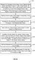
Figure 5A , an embodiment of the present invention comprises a method S10 of obtaining thermal imaging camera images from a thermal imaging camera that rotates through a plurality of stop positions (S12). The camera may capture thermal imaging camera images at a constant frame rate. At least some of the thermal imaging camera images correspond to stop positions, while other captured thermal imaging camera images may not correspond to any stop position. Thermal imaging camera images corresponding to any of the stop positions are retained (S14), while thermal imaging camera images that do not correspond to any stop position are discarded (S16). - Retained thermal imaging camera images are sent in a video stream to a video processor (S18). They may be separated into individual thermal imaging camera images, sorted, and stored for a corresponding virtual camera device that corresponds to the specific stop position to which the given image corresponds (S20). For example, the on-site system may include appropriate memory for storing the images. Alternatively, some or all of the images may be stored off-site and relayed on-site as needed. The virtual camera devices may be on-site relative to the thermal imaging camera. The thermal imaging camera images are not stitched together on-site into a panoramic image on-site, so that the total power requirements of the on-site system (e.g., including the thermal imaging camera, an indexing mechanism for rotating the camera, and a multiplexing and analysis module for sorting images for the virtual camera devices) are no more than about 10 watts (S22).
- The individual thermal imaging camera images from each stop position may be analyzed as a video stream to detect a change from a given image to a subsequent image (S24).
- Discarding images that do not correspond to any stop position may allow the video processor to periodically sleep because it never receives those images, thus making the system more power efficient. Similarly, because on-site analytics are limited to relatively simple functions (e.g., not stitching images together, etc.), the system exhibits relatively limited power consumption characteristics (e.g., less than about 10 watts, can be left unattended for a period of years and can be powered by batteries charged by relatively small solar cells).
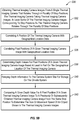
- In an example that does not form part of the invention, there is provided a method (S30 - as shown in
Figure 5B ) for correlating geographical location data including determination of depth values for pixel positions of an individual image frame of a panoramic image. The method may comprise the steps of obtaining camera images (e.g., thermal imaging camera images) from a single camera that rotates through a plurality of stop positions (S32). The camera may capture images at a constant frame rate, at least some of the images corresponding to stop positions as the camera rotates through the plurality of stop positions. A position of the camera may be correlated with geographical location data (S34), pixel positions of a given camera image may be correlated with geographical location data (S36), and depth values for pixel positions of the given camera image may be determined based at least in part on the geographical location of the camera and the orientation or position in which the given stop position is "pointed" (S38). - Optionally, depth information determinations (e.g., calculations) may be performed off-site, and relayed back to the camera system site for storage on-site (S40). In other words, the analytics and processing that correlates positions of an image with location data, determining the appropriate depth value for each pixel may be performed off-site, and the results may be relayed to the on-site system for use by the camera system, further reducing power requirements of the on-site system.
- In use, a given depth value for a pixel position of a given thermal imaging camera image may be compared to a previously or subsequently obtained thermal imaging camera image from the same stop position to determine any changes, e.g., the size or movement speed of an object shown in the thermal imaging camera images (S42).
- Although the subject matter is described in language specific to structural features and/or methodological acts, it is to be understood that the subject matter defined in the appended claims is not necessarily limited to the described features or acts described herein, or the order of the acts described herein. Rather, the described features and acts are disclosed as example forms of implementing the claims.
- Computing systems are now increasingly taking a wide variety of forms. Computing systems may, for example, be handheld devices, appliances, laptop computers, desktop computers, mainframes, distributed computing systems, or even devices that have not conventionally been considered a computing system. In this description and in the claims, the term "computing system" is defined broadly as including any device or system (or combination thereof) that includes at least one physical and tangible processor, and a physical and tangible memory capable of having thereon computer-executable instructions that may be executed by the
-
Figure 1 illustrates anexemplary computing system 100. In its most basic configuration, acomputing system 100 typically includes at least oneprocessing unit 102 andmemory 104. Thememory 104 may be physical system memory, which may be volatile, non-volatile, or some combination of the two. The term "memory" may also be used herein to refer to non-volatile mass storage such as physical storage media. If the computing system is distributed, the processing, memory and/or storage capability may be distributed as well. - Each of the computer systems described herein may be connected to one another over (or may be part of) a network, such as, for example, a Local Area Network ("LAN"), a Wide Area Network ("WAN"), and even the Internet. Accordingly, each of the described computer systems as well as any other connected computer systems and their components, can create message related data and exchange message related data (e.g., Internet Protocol ("IP") datagrams and other higher layer protocols that utilize IP datagrams, such as, Transmission Control Protocol ("TCP"), Hypertext Transfer Protocol ("HTTP"), Simple Mail Transfer Protocol ("SMTP"), etc.) over the network.
- As used herein, the term "executable module" or "executable component" can refer to software objects, routings, or methods that may be executed on the computing system. The different components, modules, engines, and services described herein may be implemented as objects or processes that execute on the computing system (e.g., as separate threads).
- In the description that follows, embodiments are described with reference to acts that are performed by one or more computing systems. If such acts are implemented in software, one or more processors of the associated computing system that performs the act direct the operation of the computing system in response to having executed computer-executable instructions. For example, such computer-executable instructions may be embodied on one or more computer-readable media that form a computer program product. An example of such an operation involves the manipulation of data. The computer-executable instructions (and the manipulated data) may be stored in the
memory 104 of thecomputing system 100.Computing system 100 may also containcommunication channels 108 that allow thecomputing system 100 to communicate with other message processors over, for example,network 110. - Embodiments described herein may comprise or utilize a special-purpose or general-purpose computer system that includes computer hardware, such as, for example, one or more processors and system memory, as discussed in greater detail below. The system memory may be included within the
overall memory 104. The system memory may also be referred to as "main memory", and includes memory locations that are addressable by the at least oneprocessing unit 102 over a memory bus in which case the address location is asserted on the memory bus itself. System memory has traditionally been volatile, but the principles described herein also apply in circumstances in which the system memory is partially, or even fully, non-volatile. - Embodiments within the scope of the present invention also include physical and other computer-readable media for carrying or storing computer-executable instructions and/or data structures. Such computer-readable media can be any available media that can be accessed by a general-purpose or special-purpose computer system. Computer-readable media that store computer-executable instructions and/or data structures are computer storage media. Computer-readable media that carry computer-executable instructions and/or data structures are transmission media. Thus, by way of example, and not limitation, embodiments of the invention can comprise at least two distinctly different kinds of computer-readable media: computer storage media and transmission media.
- Computer storage media are physical storage media that store computer-executable instructions and/or data structures. Physical storage media includes recordable-type storage devices, such as RAM, ROM, EEPROM, solid state drives ("SSDs"), flash memory, phase-change memory ("PCM"), optical disk storage, magnetic disk storage or other magnetic storage devices, or any other physical hardware storage medium(s) which can be used to store program code in the form of computer-executable instructions or data structures, and which can be accessed and executed by a general-purpose or special-purpose computer system to implement the functionality described herein.
- Transmission media can include a network and/or data links which can be used to carry program code in the form of computer-executable instructions or data structures, and which can be accessed by a general-purpose or special-purpose computer system. A "network" is defined as one or more data links that enable the transport of electronic data between computer systems and/or modules and/or other electronic devices. When information is transferred or provided over a network or another communications connection (either hardwired, wireless, or a combination of hardwired or wireless) to a computer system, the computer system may view the connection as transmission media. Combinations of the above should also be included within the scope of computer-readable media.
- Further, upon reaching various computer system components, program code in the form of computer-executable instructions or data structures can be transferred automatically from transmission media to computer storage media (or vice versa). For example, computer-executable instructions or data structures received over a network or data link can be buffered in RAM within a network interface module (e.g., a "NIC"), and then eventually transferred to computer system RAM and/or to less volatile computer storage media at a computer system. Thus, it should be understood that computer storage media can be included in computer system components that also (or even primarily) utilize transmission media.
- Computer-executable instructions comprise, for example, instructions and data which, when executed at one or more processors, cause a general-purpose computer system, special-purpose computer system, or special-purpose processing device to perform a certain function or group of functions. Computer-executable instructions may be, for example, binaries, intermediate format instructions such as assembly language, or even source code.
- Those skilled in the art will appreciate that the invention may be practiced in network computing environments with many types of computer system configurations, including, personal computers, desktop computers, laptop computers, message processors, hand-held devices, multi-processor systems, microprocessor-based or programmable consumer electronics, network PCs, minicomputers, mainframe computers, mobile telephones, PDAs, tablets, pagers, routers, switches, and the like. The invention may also be practiced in distributed system environments where local and remote computer systems, which are linked (either by hardwired data links, wireless data links, or by a combination of hardwired and wireless data links) through a network, both perform tasks. As such, in a distributed system environment, a computer system may include a plurality of constituent computer systems. In a distributed system environment, program modules may be located in both local and remote memory storage devices.
- Those skilled in the art will also appreciate that the invention may be practiced in a cloud computing environment. Cloud computing environments may be distributed, although this is not required. When distributed, cloud computing environments may be distributed internationally within an organization and/or have components possessed across multiple organizations. In this description and the following claims, "cloud computing" is defined as a model for enabling on-demand network access to a shared pool of configurable computing resources (e.g., networks, servers, storage, applications, and services). The definition of "cloud computing" is not limited to any of the other numerous advantages that can be obtained from such a model when properly deployed.
- Alternatively, or in addition, the functionally described herein can be performed, at least in part, by one or more hardware logic components. For example, and without limitation, illustrative types of hardware logic components that can be used include Field-programmable Gate Arrays (FPGAs), Program-specific Integrated Circuits (ASICs), Program-specific Standard Products (ASSPs), System-on-a-chip systems (SOCs), Complex Programmable Logic Devices (CPLDs), etc.
-
Figure 2 illustrates a block diagram forcamera system 200.Camera system 200 allows camera 250 (e.g., a thermal imaging camera) to rotate up to a full 360° around a fixed-axis. The full revolution comprises a number of positions corresponding to "stops" where it is desired that an image be captured. Because of requirements related to camera calibration, particularly with a thermal imaging camera, the camera can capture images at a constant frame rate. The spectrum captured may be from about 800 nm to about 1400 nm. Of course, it may be possible to employ concepts disclosed herein within systems configured to capture and use image data based on other spectrums (e.g., visible light, higher or lower wavelengths). When capturing images at a constant frame rate, some of the images may correspond to positions between designated "stop" positions, while others will correspond to a "stop" position. As will be described in further detail hereafter, only those images corresponding to a "stop" position may be retained. The others may be discarded. - The positions where
camera 250 captures images that will be retained are referred to herein as stop positions becausecamera 250 must be stationary, or momentarily stopped, in order forcamera 250 to acquire a non-blurry image. A stop position can be characterized as having an angle offset relative to a designated home position (i.e., "stop" 1) at whichcamera 250 captures an image. In some implementations, the system may determine the home position by using a camera-mount with a hole, along with a transmissive optical encoder that can detect the home position when the hole in the camera-mount lines up with the encoder. Such a transmissive optical encoder may be a 1-bit encoder. In other implementations, a higher resolution encoder may be used to allow more granular feedback of actual camera position at any given time. -
Camera system 200 can allow any number of stop positions per revolution. In an embodiment, the number of stop positions may be between 1 and 16. The stops may be positioned at equally spaced intervals. For example, ten stop positions, or stops, per revolution would result in ten stops that are located 36° apart. Thecamera system 200 may use any suitable motor mechanism for ensuring that the camera remains momentarily stationary at each stop position, so as to facilitate capture of a non-blurry image at each desired stop position. For example, a stepper motor may be employed to holdcamera 250 stationary at each stop position for the appropriate amount of time to acquire an image before moving to the next stop position. Details of an exemplary stepper motor mechanism are disclosed in the inventors PCT Patent Application Serial No.PCT/US/2014/033539 filed April 9, 2014 titled STEPPER MOTOR CONTROL AND FIRE DETECTION SYSTEM. Another example of a motor mechanism that may be employed in rotating the camera through a plurality of stop positions in which the camera remains stationary momentarily at each stop position includes a mechanical cam system, e.g., as described in the inventorsU.S. Patent No. 8,773,503 issued July 8, 2014 and titled AUTOMATED PANORAMIC CAMERA AND SENSOR PLATFORM WITH COMPUTER AND OPTIONAL POWER SUPPLY. Motor mechanisms as described in the above patents and applications, as well as any other suitable design may be employed. - As depicted in
Figure 2 , the system can utilize two processors,microprocessor 210 andvideo processor 240.Microprocessor 210 can manage position and timing ofcamera 250, whilevideo processor 240 can process video fromcamera 250. Utilizing two processors allows the real-time performance of thecamera 250 and motor synchronization by themicroprocessor 210 to be de-coupled from the high-throughput video processor 240. Alternatively, some implementations may use one processor to manage position and timing, as well as video of thecamera 250. Of course, more than two processors could alternatively be employed. - In an implementation, data from the
camera 250 passes throughslip rings 260, which allows thecamera 250 to rotate as described above (continuous rotation with intermittent, very short stops). Because the periods where the camera is actually stationary are so short, the camera may appear to rotate continuously. In some cases, the camera frame rate may not exactly match the rotational speed and stop rate of thecamera system 200, thus creating fractional video frames.Digital switch 230 may then be used to throw away any unwanted video frames. In other words, as described above, some captured frames may correspond to one of the stop positions, while other captured frames may be captured while the camera is rotating. Using thedigital switch 230 allows thevideo processor 240 to sleep during those times at which unwanted video frames are discarded, thus creating better power efficiency. Of course, in other embodiments of the system, the video processor (e.g., ARM/DSP) may have little or no time to sleep. - Where an image is taken at each stop position, each stop position can be represented as an individual virtual camera. A virtual camera may act like a stationary camera pointed in a single direction. The
camera system 200 can support any number of stop positions and corresponding number of virtual cameras. In an embodiment,system 200 may include from 1 to 16 stop positions, and 1 to 16 virtual cameras, each virtual camera associated with a particular stop position.Figure 3A illustrates how each stop position may correlate to a physical space with thecamera 250 facing stop position 1 (i.e., home position).Figure 3B shows thecamera 250 having rotated so as to be facingstop position 5. As depicted inFigures 3A and3B , a numbering system used for the stop positions may increase in a clockwise direction.Figures 3A and3B illustrate an exemplary configuration including 8 stop positions, although it will be understood that more or fewer stop positions may be provided. By way of example, the number of stop positions may be from 2 to about 30, from 4 to about 20, or from 6 to about 16. - The period in which the camera is momentarily stopped may be any suitable period of time (e.g., may depend on the characteristics of the image capture capabilities of the camera). In an embodiment, each stop period (i.e., the dwell time) may be from about 30 ms to about 120 ms (e.g., about 60 ms).
- Each image captured by
camera 250 corresponding to a stop position may be multiplexed, or muxed, into a video stream and sent tovideo processor 240. Each image captured bycamera 250 to be retained may be sent out of the camera over the same interface.Microprocessor 210 can manage and track the angle offset (and corresponding stop position) ofcamera 250 when an image to be retained is captured (i.e., the image corresponds to a stop position). Even images that are to be discarded (i.e., the image does not correspond to a stop position), may be sent todigital switch 230 over the same interface as retained images. Atdigital switch 230, those images that are to be discarded may be separated and discarded, rather than passed on tovideo processor 240. - An exemplary implementation showing how
video processor 240 may operate is described in more detail inFigure 4 . Referring toFigure 4 ,video demultiplexing driver 430 separates the video stream into individual images (i.e., frames) that each correspond to a particular stop position, or virtual camera. For example, the video stream referred to at this stage may include images to be retained that were captured at different stop positions.Demulitplexing driver 430 may use position information tracked bymicroprocessor 210 to determine the corresponding virtual camera for each image of the video stream, allowing sorting of the images to their proper virtual camera devices. As illustrated byFigure 4 , each image can be sent to its corresponding virtual camera (401 - 408) for storage and future analytics (e.g., comparison of images taken adjacent in time from the same stop position), once that determination has been made. - If desired, images from different stop positions may be stitched together to create a panoramic image (e.g., of up to 360°). An advantage of the present embodiments is that any such stitching is optional, and is typically not carried out on-site (if at all). If done, stitching may be done off-site, allowing the total power requirements for on-
site system 200 to be no more than about 10 watts, as stitching is power and computer processor intensive. - In some implementations, the video stream associated with a given virtual camera device may be analyzed to detect a change from a given image to a subsequent image. In other words, rather than stitching together images to create a panoramic image, the analytics carried out may involve comparison of an image with a subsequently captured image (or a previously captured image) from the same stop position (and thus the same virtual camera device) to detect any changes (e.g., a change in temperature of an object, movement of an object, etc.). For example, the analytics carried out may include fire detection, as discussed in the inventors' prior PCT Patent Application Serial No.
PCT/US/2014/033539 filed April 9, 2014 titled STEPPER MOTOR CONTROL AND FIRE DETECTION SYSTEM, and PCT Patent Application Serial No.PCT/US/2014/033547 filed April 9, 2014 titled FIRE DETECTION SYSTEM. - By capturing thermal image data and subjecting the thermal image data to analytics, background masking can be simplified as compared to visible spectrum data, simplifying object identification.
- Power may be supplied to the on-site system using batteries that are charged via solar cells, which can allow the system to be placed in a given location (e.g., remote, off the power grid) for long periods of time, such as up to two years or more. Lifespan may be shorter or longer than 2 years, depending on the system characteristics.
- Each virtual camera can have a video stream similar to that which would be obtained by a stationary camera placed at the corresponding stop position. The system of virtual cameras may be on-site relative to
thermal imaging camera 250. In some implementations, the frame rate of a virtual camera video stream is equal to the rotational speed ofmotor 270, ascamera 250 passes each stop once per revolution. The muxed signal frame rate may be equal to a rotational speed ofmotor 270 multiplied by the number of stops per revolution. For example, a system running at 30 RPM with 16 stops per revolution would have a muxed frame rate of 8 frames per second (FPS) and each virtual camera device would have a frame rate of ½ FPS, or 1 frame per 2 seconds (e.g., 30 RPM / 60 seconds in a minute = 0.5 FPS). - Utilizing virtual cameras can allow analytics and any stitching to be decoupled from image acquisition. Because each virtual camera can have its own video stream, images associated with each virtual camera can be processed independently.
System 200 may normally capture images in numerical (e.g., clockwise or counter-clockwise) order, but because the angle offset from home position (i.e., stop position 1) is known based on the stop number of the virtual camera, analytics or any stitching may update in any order desired. - In some implementations, the position of
camera 250 at which an image is captured can be correlated with actual geographical location data (e.g., GPS data). Once it is known where theactual camera 250 is located, based on geographical location data, the camera can be located on a 3D topography map. Similarly, depth values for individual pixels of a given frame of a given virtual camera device (i.e., stop position) may be determined. Corrections may be made for tilt and height. - Additional details of exemplary fire detection systems, including the ability to correlation of geographical location data and determination of depth values is found in PCT Patent Application Serial No.
PCT/US/2014/033547 filed April 9, 2014 titled FIRE DETECTION SYSTEM. - Correlating geographical location data with the position of
camera 250 can include, but is not limited to, correlating pixel positions of a captured image and determining depth values for pixel positions of individual thermal imaging camera images based on the geographical location ofthermal imaging camera 250. Given the elevation and orientation ofthermal imaging camera 250, the distance or depth value for each pixel of an image may be calculated using elevation data, for example, from the National Elevation Dataset. - The depth value calculation to be associated with a given pixel can be done in a series of steps for determining (e.g., calculating) how each pixel represents a ray projected from the camera across the landscape intersecting the ground. Generally, this may be achieved by using a projected camera view on a wireframe terrain model created using elevation data (e.g., from the National Elevation Dataset) to estimate where each rendered pixel of the camera view would intersect the wireframe to calculate the probable "z" depth value of the bottom of each image element or pixel. Such a process may employ a loop process carried out through increasing z-distances until the projected height intersects the elevation height at a distance.
- This may be done by determining (e.g., calculating) if a ray having a length equal to the camera's height intersects the ground at the projected distance. This determination may be repeated by repeatedly increasing the ray length by a given amount (e.g., 1 decimeter) until the ground is reached (e.g., intersected) or the ray exceeds a given length (e.g., 30 kilometers). Such an excessive length may be used to help render the horizon. Data for latitude, longitude, elevation and distance of the intersection point may be stored, and the determination (e.g., calculation) may be repeated for the next pixel of a column. Progressing upwardly from the bottom, within the image, once a column of pixels reaches the horizon, the determination may move onto a new column. Such determinations or calculations may be based off variable Vertical Field of View, Horizontal Field of View, elevation and orientation. The final data set may be used to render an image that depicts distance (e.g., in gray scale) with lines placed at a given distance (e.g., every 100 meters). The determined or calculated image may be compared against an actual image for a final adjustment of the input variables. Once completed, the final result would provide a "z" depth value map that can be saved for future immediate analytics availability.
- Illustrative of the steps described above, an image of 640x512 may require repetition of the described determinations approximately 250,000 times.
- Once depth values for pixel positions are determined, this may allow determination of the size or movement speed of an object captured within an image. For example, it may provide information on the size or movement speed of a wildfire. Processing that correlates pixel positions of an image with location data and determination of a depth value associated with each pixel may be performed off-site at a remote user interface terminal. The actual depth values associated with given pixels of the images may be relayed to the camera system for storage and use on-site.
- Relay of any data on-site to off-site or vice versa may be by any suitable mechanism, e.g., including, but not limited to satellite link or network, cellular link or network, WiFi link or network, radio transmission, hard wired link or network, etc.
- The present invention may be embodied in other specific forms without departing from its scope.
- The described embodiments are to be considered in all respects only as illustrative and not restrictive. The scope of the invention is, therefore, defined by the appended claims rather than by the foregoing description.
Claims (10)
- An on-site system (200) for analysing and sorting individual image frames of panoramic image data using a plurality of virtual camera devices (401-408), the system (200) comprising:an indexing mechanism on which a thermal imaging camera (250) is mounted for rotating the camera (250) through a plurality of stop positions;the thermal imaging camera (250) being configured to take thermal imaging camera images, at least some of the thermal imaging camera images corresponding to stop positions as the thermal imaging camera (250) rotates through the plurality of stop positions;a multiplexing and analysis module configured to discard any thermal imaging camera image that does not correspond to any of the stop positions, so that only the thermal imaging camera images that correspond to any one of the stop positions are retained, wherein the multiplexing and analysis module comprisesa first processor (210) configured to manage position and timing of the thermal imaging camera (250), including tracking an angle offset relative to a home position at which a thermal imaging camera image is captured,a second processor that is a video processor (240) which is configured to process a video stream from the thermal imaging camera (250),a digital switch (230) that is configured to discard the thermal imaging camera images that do not correspond to any stop position, so that only the thermal imaging camera images corresponding to any one of the stop positions are retainedwherein the video processor (240) sleeps during discarding of images that do not correspond to any designated stop position;the video processor (240) being configured to process the video stream of the retained thermal imaging camera images by separating the video stream of retained thermal imaging camera images into individual thermal imaging camera images corresponding to specific stop positions and storing the retained thermal imaging camera images for a plurality of corresponding virtual camera devices (401 - 408);wherein real-time performance of the thermal imaging camera (250) and motor synchronization by the first processor (210) are de-coupled from high-throughput video processing by the video processor (240);the plurality of virtual camera devices (401 - 408) being on-site relative to the thermal imaging camera, each virtual camera device (401 - 408) of the plurality of virtual camera devices (401 - 408) corresponding to a specific stop position and each of the virtual camera devices (401 - 408) having a separate, corresponding video stream, each separate, corresponding video stream comprising a plurality of images corresponding to a specific stop position.
- The system (200) in accordance with Claim 1, wherein the thermal imaging camera (250) takes the thermal imaging camera images at a constant frame rate.
- The system (200) in accordance with Claim 2, wherein the on-site multiplexing and analysis module comprises a demultiplexing driver (430) that separates the video stream of retained thermal imaging camera images, sorting the retained images to be stored for the corresponding virtual camera device (401 - 408) and wherein the demultiplexing driver (430) utilizes position information provided by the first processor (210) to determine which stop position a given image corresponds to.
- The system (200) in accordance with Claim 1, wherein the retained thermal imaging camera images are sent from the camera (250) to the digital switch (230) of the multiplexing and analysis module through slip rings (260) so that the camera (250) can rotate continuously.
- The system (200) in accordance with Claim 1, wherein the digital switch (230) receives both those images corresponding to any one of the stop positions and those images that do not correspond to any stop position, those images which correspond to any stop position being sent to the video processor.
- The system (200) in accordance with Claim 1, wherein the camera (250) is physically stationary when capturing images corresponding to each stop position and the camera (250) is not physically stationary when capturing images that do not correspond to any designated stop position.
- The system (200) in accordance with Claim 1, wherein each image captured by the camera (250) is sent out of the camera (250) over the same interface.
- A method (S10) for analyzing and sorting individual image frames of panoramic image data using a plurality of virtual camera devices (401 - 408), the method comprising:using a first processor (210) to manage position and timing of a thermal imaging camera (250), including tracking and angle offset relative to a home position at which a thermal imaging camera image is captured;obtaining (S12) thermal imaging camera images from the thermal imaging camera (250) that rotates through a plurality of stop positions, the thermal imaging camera (250) taking thermal imaging camera images, at least some of the thermal imaging camera images corresponding to stop positions as the thermal imaging camera (250) rotates through the plurality of stop positions;using a digital switch (230) to retain (S14) thermal imaging camera images corresponding to any one of the stop positions and discard (S16) any thermal imaging camera image that does not correspond to any designated stop position;sending (S18) retained thermal imaging camera images in a video stream to second processor that is a video processor (240);using the video processor (240) to process the video stream from the thermal imaging camera (250), the video processor (240) sleeping during discarding of images that do not correspond to any designated stop position;wherein real-time performance of the thermal imaging camera (250) and motor synchronization by the first processor (210) are de-coupled from high-throughput video processing by the video processor (240);
andseparating (S20) the video stream into individual thermal imaging camera images and storing the thermal imaging camera images for a plurality of corresponding virtual camera devices (401 - 408), each virtual camera device (401 - 408) corresponding to a specific stop position, and each virtual camera device (401 - 408) having a separate, corresponding video stream, each separate corresponding video stream comprising a plurality of images corresponding to a specific stop position, the virtual camera devices (401 - 408) being on-site relative to the thermal imaging camera (250). - The method (S10) in accordance with Claim 8, wherein the individual thermal imaging camera images from each stop position are analyzed as a video stream to detect a change from a given image to a subsequent image.
- The method (S10, S30) in accordance with Claim 8, further comprising:correlating (S34) a position of the thermal imaging camera (250) with geographical location data;correlating (S36) pixel positions of a given thermal imaging camera image with geographical location data; anddetermining (S38) depth values for pixel positions of a given thermal imaging camera image based at least in part on the geographical location of the thermal imaging camera (250).
Applications Claiming Priority (2)
| Application Number | Priority Date | Filing Date | Title |
|---|---|---|---|
| US201361864196P | 2013-08-09 | 2013-08-09 | |
| PCT/US2014/049986 WO2015021186A1 (en) | 2013-08-09 | 2014-08-06 | Methods for analyzing thermal image data using a plurality of virtual devices and methods for correlating depth values to image pixels |
Publications (3)
| Publication Number | Publication Date |
|---|---|
| EP3030935A1 EP3030935A1 (en) | 2016-06-15 |
| EP3030935A4 EP3030935A4 (en) | 2017-09-27 |
| EP3030935B1 true EP3030935B1 (en) | 2020-11-18 |
Family
ID=52461914
Family Applications (1)
| Application Number | Title | Priority Date | Filing Date |
|---|---|---|---|
| EP14835456.6A Active EP3030935B1 (en) | 2013-08-09 | 2014-08-06 | Methods for analyzing thermal image data using a plurality of virtual devices and methods for correlating depth values to image pixels |
Country Status (7)
| Country | Link |
|---|---|
| US (5) | US9348196B1 (en) |
| EP (1) | EP3030935B1 (en) |
| JP (1) | JP6581086B2 (en) |
| KR (1) | KR102248161B1 (en) |
| CN (2) | CN108495051B (en) |
| MX (1) | MX360725B (en) |
| WO (1) | WO2015021186A1 (en) |
Families Citing this family (19)
| Publication number | Priority date | Publication date | Assignee | Title |
|---|---|---|---|---|
| NL2008639C2 (en) * | 2012-04-13 | 2013-10-16 | Cyclomedia Technology B V | Device, system and vehicle for recording panoramic images, and a device and method for panoramic projection thereof. |
| EP2984640B1 (en) | 2013-04-09 | 2019-12-18 | Thermal Imaging Radar, LLC | Fire detection system |
| WO2014169061A1 (en) | 2013-04-09 | 2014-10-16 | Thermal Imaging Radar, Llc. | Stepper motor control and fire detection system |
| KR102248161B1 (en) | 2013-08-09 | 2021-05-04 | 써멀 이미징 레이다 엘엘씨 | Methods for analyzing thermal image data using a plurality of virtual devices and methods for correlating depth values to image pixels |
| US10366509B2 (en) | 2015-03-31 | 2019-07-30 | Thermal Imaging Radar, LLC | Setting different background model sensitivities by user defined regions and background filters |
| USD776181S1 (en) | 2015-04-06 | 2017-01-10 | Thermal Imaging Radar, LLC | Camera |
| JP6582805B2 (en) * | 2015-09-25 | 2019-10-02 | 富士通株式会社 | Encoding apparatus, encoding system, encoding method, and program |
| US10277824B2 (en) * | 2016-03-10 | 2019-04-30 | Visbit Inc. | Time multiplexing programmable field of view imaging |
| US9888179B1 (en) * | 2016-09-19 | 2018-02-06 | Google Llc | Video stabilization for mobile devices |
| CN106652300B (en) * | 2016-12-23 | 2019-03-15 | 中科星图股份有限公司 | A kind of fire point monitoring method applied to forest zone |
| CN107424182B (en) * | 2017-05-03 | 2024-04-12 | 北京海顿中科技术有限公司 | Thermal imaging field monitoring device and method |
| US10574886B2 (en) | 2017-11-02 | 2020-02-25 | Thermal Imaging Radar, LLC | Generating panoramic video for video management systems |
| EP3553697B1 (en) | 2018-04-13 | 2023-06-07 | Thermal Imaging Radar, LLC | Generating panoramic video for video management systems |
| CN108520615B (en) * | 2018-04-20 | 2020-08-25 | 吉林省林业科学研究院 | Fire identification system and method based on image |
| US11280500B2 (en) | 2018-08-03 | 2022-03-22 | Pixart Imaging Inc. | Auto detection system based on thermal signals |
| US10871394B2 (en) * | 2018-08-03 | 2020-12-22 | Pixart Imaging Inc. | Optical sensor assembly |
| US11601605B2 (en) * | 2019-11-22 | 2023-03-07 | Thermal Imaging Radar, LLC | Thermal imaging camera device |
| CN111726522B (en) * | 2020-06-12 | 2021-06-11 | 上海摩勤智能技术有限公司 | Face recognition equipment control method and device |
| KR102448584B1 (en) * | 2022-02-24 | 2022-09-29 | 케비스전자 주식회사 | Panoramic thermal imaging temperature monitoring system using rotating multi-array thermopoly sensor |
Family Cites Families (205)
| Publication number | Priority date | Publication date | Assignee | Title |
|---|---|---|---|---|
| US3336810A (en) | 1964-04-28 | 1967-08-22 | Sperry Rand Corp | Antifriction support means for gyroscopes |
| US3648384A (en) | 1970-04-07 | 1972-03-14 | Borg Warner | Turntable drive release mechanism |
| US3769501A (en) | 1973-01-02 | 1973-10-30 | Gte Sylvania Inc | Selective actuating mechanism for percussive photoflash lamp array |
| US4977323A (en) * | 1973-08-16 | 1990-12-11 | The United States Of America As Represented By The Secretary Of The Navy | 360 degree infrared surveillance with panoramic display |
| US3883788A (en) | 1973-10-26 | 1975-05-13 | Sperry Sun Well Surveying Co | Gyroscope orientation controller |
| US4263513A (en) | 1979-02-28 | 1981-04-21 | Compagnie Generale De Radiologie | Apparatus for panoramic radiography |
| GB2104321B (en) | 1981-07-21 | 1985-07-10 | Shinshu Seiki Kk | Method of and apparatus for controlling a stepping motor |
| US4602857A (en) | 1982-12-23 | 1986-07-29 | James H. Carmel | Panoramic motion picture camera and method |
| GB2189329B (en) | 1986-03-03 | 1990-10-24 | Canon Kk | Camera |
| US4710691A (en) | 1986-03-27 | 1987-12-01 | Anacomp, Inc. | Process and apparatus for characterizing and controlling a synchronous motor in microstepper mode |
| JPH02188196A (en) | 1989-01-13 | 1990-07-24 | Copal Co Ltd | Controlling method for driving of stepper motor |
| US4922275A (en) | 1989-09-25 | 1990-05-01 | Burle Technologies, Inc. | Automatic panoramic camera mount |
| US6088534A (en) | 1990-09-19 | 2000-07-11 | Minolta Co., Ltd. | Camera having an aperture controllable shutter |
| US5990941A (en) | 1991-05-13 | 1999-11-23 | Interactive Pictures Corporation | Method and apparatus for the interactive display of any portion of a spherical image |
| US5652643A (en) * | 1992-03-17 | 1997-07-29 | Sony Corporation | Photographic and video image system |
| US5650813A (en) * | 1992-11-20 | 1997-07-22 | Picker International, Inc. | Panoramic time delay and integration video camera system |
| BR9301438A (en) * | 1993-04-05 | 1994-11-15 | Petroleo Brasileiro Sa | Process of preparation of spherical ziegler catalyst for polymerization of alpha-olefins, spherical catalyst, process of obtaining spherical polyethylene of very high molecular weight and spherical polyethylene of very high by molecular |
| US5453618A (en) * | 1994-01-31 | 1995-09-26 | Litton Systems, Inc. | Miniature infrared line-scanning imager |
| US5598207A (en) | 1994-04-12 | 1997-01-28 | Hughes Electronics | Camera pointing mechanism using proximate magnetic sensing |
| US7724278B2 (en) | 1995-05-30 | 2010-05-25 | Maguire Francis J Jr | Apparatus with moveable headrest for viewing images from a changing direction-of-view |
| US20070061735A1 (en) | 1995-06-06 | 2007-03-15 | Hoffberg Steven M | Ergonomic man-machine interface incorporating adaptive pattern recognition based control system |
| US5752113A (en) | 1995-12-22 | 1998-05-12 | Borden; John | Panoramic indexing camera mount |
| USD381997S (en) | 1996-01-30 | 1997-08-05 | Sony Corporation | Video camera |
| US5790183A (en) | 1996-04-05 | 1998-08-04 | Kerbyson; Gerald M. | High-resolution panoramic television surveillance system with synoptic wide-angle field of view |
| US6133943A (en) * | 1996-09-30 | 2000-10-17 | Intel Corporation | Method and apparatus for producing a composite image |
| JP4332231B2 (en) * | 1997-04-21 | 2009-09-16 | ソニー株式会社 | Imaging device controller and imaging system |
| US6545701B2 (en) | 1997-08-13 | 2003-04-08 | Georgia Tech Research Corporation | Panoramic digital camera system and method |
| US6229546B1 (en) | 1997-09-09 | 2001-05-08 | Geosoftware, Inc. | Rapid terrain model generation with 3-D object features and user customization interface |
| US6034716A (en) * | 1997-12-18 | 2000-03-07 | Whiting; Joshua B. | Panoramic digital camera system |
| US6304284B1 (en) * | 1998-03-31 | 2001-10-16 | Intel Corporation | Method of and apparatus for creating panoramic or surround images using a motion sensor equipped camera |
| US6304285B1 (en) | 1998-06-16 | 2001-10-16 | Zheng Jason Geng | Method and apparatus for omnidirectional imaging |
| US6628338B1 (en) | 1998-07-08 | 2003-09-30 | Elbex Video Ltd. | Direct drive electric motor apparatus incorporating slip ring assembly |
| US6195204B1 (en) | 1998-08-28 | 2001-02-27 | Lucent Technologies Inc. | Compact high resolution panoramic viewing system |
| US7023913B1 (en) | 2000-06-14 | 2006-04-04 | Monroe David A | Digital security multimedia sensor |
| US20030025599A1 (en) | 2001-05-11 | 2003-02-06 | Monroe David A. | Method and apparatus for collecting, sending, archiving and retrieving motion video and still images and notification of detected events |
| CA2344380A1 (en) | 1998-09-18 | 2000-03-30 | Paul E. Kerouac | In vessel composting process and apparatus |
| US6023588A (en) * | 1998-09-28 | 2000-02-08 | Eastman Kodak Company | Method and apparatus for capturing panoramic images with range data |
| US6215115B1 (en) | 1998-11-12 | 2001-04-10 | Raytheon Company | Accurate target detection system for compensating detector background levels and changes in signal environments |
| US20150297949A1 (en) | 2007-06-12 | 2015-10-22 | Intheplay, Inc. | Automatic sports broadcasting system |
| JP2000156806A (en) * | 1998-11-20 | 2000-06-06 | Sony Corp | Video camera |
| JP2000243062A (en) | 1999-02-17 | 2000-09-08 | Sony Corp | Device and method for video recording and centralized monitoring and recording system |
| JP3620327B2 (en) * | 1999-02-17 | 2005-02-16 | 富士通株式会社 | Electronic equipment |
| US6539162B1 (en) * | 1999-03-30 | 2003-03-25 | Eastman Kodak Company | Photographing a panoramic image produced from a captured digital image |
| US6738073B2 (en) | 1999-05-12 | 2004-05-18 | Imove, Inc. | Camera system with both a wide angle view and a high resolution view |
| US6327327B1 (en) * | 1999-09-27 | 2001-12-04 | Picker International, Inc. | Multi-channel segmented slip ring |
| JP4439045B2 (en) | 1999-10-07 | 2010-03-24 | 日本電産コパル株式会社 | Step motor drive device |
| US6678001B1 (en) * | 1999-11-01 | 2004-01-13 | Elbex Video Ltd. | Ball shaped camera housing with simplified positioning |
| JP2001154295A (en) * | 1999-11-30 | 2001-06-08 | Matsushita Electric Ind Co Ltd | Omniazimuth vision camera |
| US20010026684A1 (en) | 2000-02-03 | 2001-10-04 | Alst Technical Excellence Center | Aid for panoramic image creation |
| US7129971B2 (en) | 2000-02-16 | 2006-10-31 | Immersive Media Company | Rotating scan self-cleaning camera |
| WO2001089221A1 (en) | 2000-05-18 | 2001-11-22 | Imove Inc. | Multiple camera video system which displays selected images |
| US6731799B1 (en) | 2000-06-01 | 2004-05-04 | University Of Washington | Object segmentation with background extraction and moving boundary techniques |
| US6788333B1 (en) | 2000-07-07 | 2004-09-07 | Microsoft Corporation | Panoramic video |
| USD435577S (en) | 2000-07-27 | 2000-12-26 | Mcbride Richard L | Video camera housing |
| US6677982B1 (en) * | 2000-10-11 | 2004-01-13 | Eastman Kodak Company | Method for three dimensional spatial panorama formation |
| US20110058036A1 (en) * | 2000-11-17 | 2011-03-10 | E-Watch, Inc. | Bandwidth management and control |
| US7126630B1 (en) | 2001-02-09 | 2006-10-24 | Kujin Lee | Method and apparatus for omni-directional image and 3-dimensional data acquisition with data annotation and dynamic range extension method |
| JP2002314846A (en) | 2001-04-09 | 2002-10-25 | Toshiba Corp | Imaging unit and drive unit |
| US6586898B2 (en) | 2001-05-01 | 2003-07-01 | Magnon Engineering, Inc. | Systems and methods of electric motor control |
| US6782363B2 (en) | 2001-05-04 | 2004-08-24 | Lucent Technologies Inc. | Method and apparatus for performing real-time endpoint detection in automatic speech recognition |
| KR200252100Y1 (en) | 2001-08-07 | 2001-11-23 | 정운기 | Bullet camera for closed circuit television |
| US7940299B2 (en) | 2001-08-09 | 2011-05-10 | Technest Holdings, Inc. | Method and apparatus for an omni-directional video surveillance system |
| US6948402B1 (en) | 2001-09-12 | 2005-09-27 | Centricity Corporation | Rotary work table with cycloidal drive gear system |
| JP2003123157A (en) * | 2001-10-15 | 2003-04-25 | Masahiro Aoki | Building provided with environmental disaster preventing function and environment security system |
| JP4010444B2 (en) | 2002-02-28 | 2007-11-21 | シャープ株式会社 | Omnidirectional monitoring control system, omnidirectional monitoring control method, and omnidirectional monitoring control program |
| US6788198B2 (en) | 2002-03-12 | 2004-09-07 | Bob F. Harshaw | System for verifying detection of a fire event condition |
| US7259496B2 (en) | 2002-04-08 | 2007-08-21 | University Of North Carolina At Charlotte | Tunable vibratory actuator |
| JP3925299B2 (en) | 2002-05-15 | 2007-06-06 | ソニー株式会社 | Monitoring system and method |
| US20070000317A1 (en) | 2002-07-16 | 2007-01-04 | Umberto Berti | System and method for territory thermal monitoring |
| US7419375B2 (en) | 2002-08-19 | 2008-09-02 | Ormco Corporation | Aesthetic self-ligating orthodontic bracket |
| JP4048907B2 (en) | 2002-10-15 | 2008-02-20 | セイコーエプソン株式会社 | Panorama composition of multiple image data |
| US20040075741A1 (en) * | 2002-10-17 | 2004-04-22 | Berkey Thomas F. | Multiple camera image multiplexer |
| USD482712S1 (en) | 2003-01-07 | 2003-11-25 | Joe Hsu | Digital camera |
| US7157879B2 (en) | 2003-01-30 | 2007-01-02 | Rensselaer Polytechnic Institute | On-hardware optimization of stepper-motor system performance |
| US20040179098A1 (en) | 2003-02-25 | 2004-09-16 | Haehn Craig S. | Image reversing for infrared camera |
| USD486847S1 (en) | 2003-04-09 | 2004-02-17 | Sony Corporation | Video camera |
| US6809887B1 (en) * | 2003-06-13 | 2004-10-26 | Vision Technologies, Inc | Apparatus and method for acquiring uniform-resolution panoramic images |
| US8824730B2 (en) | 2004-01-09 | 2014-09-02 | Hewlett-Packard Development Company, L.P. | System and method for control of video bandwidth based on pose of a person |
| US7436438B2 (en) | 2004-03-16 | 2008-10-14 | Creative Technology Ltd. | Digital still camera and method of forming a panoramic image |
| US7487029B2 (en) | 2004-05-21 | 2009-02-03 | Pratt & Whitney Canada | Method of monitoring gas turbine engine operation |
| US6991384B1 (en) | 2004-05-27 | 2006-01-31 | Davis Robert C | Camera tripod rotating head |
| JP2006013832A (en) * | 2004-06-25 | 2006-01-12 | Nippon Hoso Kyokai <Nhk> | Video photographing apparatus and video photographing program |
| JP2006013923A (en) | 2004-06-25 | 2006-01-12 | Sony Corp | Surveillance apparatus |
| JP2006033257A (en) * | 2004-07-14 | 2006-02-02 | Fujitsu Ltd | Image distribution apparatus |
| JP2008507229A (en) | 2004-07-19 | 2008-03-06 | グランドアイ,エルティーディー | Automatic expansion of zoom function of wide-angle video camera |
| US7381952B2 (en) | 2004-09-09 | 2008-06-03 | Flir Systems, Inc. | Multiple camera systems and methods |
| USD520548S1 (en) | 2004-10-26 | 2006-05-09 | Inventec Multimedia & Telecom Corporation | Image recorder |
| US20060179463A1 (en) | 2005-02-07 | 2006-08-10 | Chisholm Alpin C | Remote surveillance |
| TWI427440B (en) | 2005-04-06 | 2014-02-21 | Kodak Graphic Comm Canada Co | Methods and apparatus for correcting banding of imaged regular patterns |
| JP2006333133A (en) | 2005-05-26 | 2006-12-07 | Sony Corp | Imaging apparatus and method, program, program recording medium and imaging system |
| US7424218B2 (en) | 2005-07-28 | 2008-09-09 | Microsoft Corporation | Real-time preview for panoramic images |
| CN1971336A (en) * | 2005-11-22 | 2007-05-30 | 三星电子株式会社 | Light deflecting apparatus |
| JP4740723B2 (en) | 2005-11-28 | 2011-08-03 | 富士通株式会社 | Image analysis program, recording medium storing the program, image analysis apparatus, and image analysis method |
| US7460773B2 (en) | 2005-12-05 | 2008-12-02 | Hewlett-Packard Development Company, L.P. | Avoiding image artifacts caused by camera vibration |
| USD548369S1 (en) | 2006-02-08 | 2007-08-07 | Koninklijke Philips Electronics N.V. | Energy saving filament lamp |
| JP2007271869A (en) * | 2006-03-31 | 2007-10-18 | Digital Service International Co Ltd | Map creating method by image processing, its device and its computer program |
| EP1876828B1 (en) | 2006-07-03 | 2016-10-26 | Axis AB | Method and apparatus for configuring parameter values for cameras |
| US9369679B2 (en) | 2006-11-07 | 2016-06-14 | The Board Of Trustees Of The Leland Stanford Junior University | System and process for projecting location-referenced panoramic images into a 3-D environment model and rendering panoramic images from arbitrary viewpoints within the 3-D environment model |
| US20080159732A1 (en) | 2006-12-29 | 2008-07-03 | Stuart Young | Positioning device |
| US8203714B2 (en) | 2007-03-13 | 2012-06-19 | Thomas Merklein | Method for the camera-assisted detection of the radiation intensity of a gaseous chemical reaction product and uses of said method and corresponding device |
| ES2633742T3 (en) | 2007-03-16 | 2017-09-25 | L-3 Communications Corporation | System for panoramic image processing |
| JP2008236632A (en) * | 2007-03-23 | 2008-10-02 | Hitachi Ltd | Image processing apparatus and method thereof |
| US7949172B2 (en) | 2007-04-27 | 2011-05-24 | Siemens Medical Solutions Usa, Inc. | Iterative image processing |
| KR100882011B1 (en) | 2007-07-29 | 2009-02-04 | 주식회사 나노포토닉스 | Methods of obtaining panoramic images using rotationally symmetric wide-angle lenses and devices thereof |
| US7863851B2 (en) | 2007-08-22 | 2011-01-04 | National Instruments Corporation | Closed loop stepper motor control |
| US8094943B2 (en) | 2007-09-27 | 2012-01-10 | Behavioral Recognition Systems, Inc. | Background-foreground module for video analysis system |
| KR20090067762A (en) | 2007-12-21 | 2009-06-25 | 삼성전기주식회사 | Camera module |
| US8139113B2 (en) | 2007-12-26 | 2012-03-20 | Utc Fire & Security Americas Corporation, Inc. | Method and system for operating a camera assembly |
| US20100097444A1 (en) | 2008-10-16 | 2010-04-22 | Peter Lablans | Camera System for Creating an Image From a Plurality of Images |
| US8355042B2 (en) | 2008-10-16 | 2013-01-15 | Spatial Cam Llc | Controller in a camera for creating a panoramic image |
| TW201001338A (en) | 2008-06-16 | 2010-01-01 | Huper Lab Co Ltd | Method of detecting moving objects |
| US8842219B2 (en) | 2008-07-23 | 2014-09-23 | Entropic Communications, Inc. | Frame rate up-conversion |
| US9185361B2 (en) | 2008-07-29 | 2015-11-10 | Gerald Curry | Camera-based tracking and position determination for sporting events using event information and intelligence data extracted in real-time from position information |
| KR101030719B1 (en) | 2008-09-25 | 2011-04-22 | 주식회사 로텍 | Slip ring with sensor magnet |
| US8223206B2 (en) | 2008-10-15 | 2012-07-17 | Flir Systems, Inc. | Infrared camera filter wheel systems and methods |
| WO2010063830A1 (en) | 2008-12-05 | 2010-06-10 | Micronic Laser Systems Ab | Rotating arm for writing or reading an image on a workpiece |
| US7991575B2 (en) | 2009-01-08 | 2011-08-02 | Trimble Navigation Limited | Method and system for measuring angles based on 360 degree images |
| CN102388391B (en) | 2009-02-10 | 2014-01-22 | 汤姆森特许公司 | Video matting based on foreground-background constraint propagation |
| GB0908200D0 (en) * | 2009-05-13 | 2009-06-24 | Red Cloud Media Ltd | Method of simulation of a real physical environment |
| US8744121B2 (en) | 2009-05-29 | 2014-06-03 | Microsoft Corporation | Device for identifying and tracking multiple humans over time |
| US8499239B2 (en) | 2009-08-28 | 2013-07-30 | Microsoft Corporation | Globe container |
| CN101719299B (en) | 2009-11-10 | 2012-03-28 | 天津市浦海新技术有限公司 | Alarm system and method for fire and combustible gas |
| KR20110052124A (en) | 2009-11-12 | 2011-05-18 | 삼성전자주식회사 | Method for generating and referencing panorama image and mobile terminal using the same |
| US8320621B2 (en) | 2009-12-21 | 2012-11-27 | Microsoft Corporation | Depth projector system with integrated VCSEL array |
| EP2481679A4 (en) * | 2010-01-12 | 2015-05-06 | Chwei-Jei Tsai | Pet bottle lid and manufacturing method thereof |
| US8905311B2 (en) | 2010-03-11 | 2014-12-09 | Flir Systems, Inc. | Infrared camera with infrared-transmissive dome systems and methods |
| JP2011199750A (en) * | 2010-03-23 | 2011-10-06 | Olympus Corp | Image capturing terminal, external terminal, image capturing system, and image capturing method |
| JP2011239195A (en) * | 2010-05-11 | 2011-11-24 | Sanyo Electric Co Ltd | Electronic apparatus |
| US8625897B2 (en) | 2010-05-28 | 2014-01-07 | Microsoft Corporation | Foreground and background image segmentation |
| CN103250405B (en) * | 2010-07-16 | 2016-08-17 | 双光圈国际株式会社 | Flash system for multiple aperture imaging |
| USD640721S1 (en) | 2010-08-09 | 2011-06-28 | Scott Satine | Cannon-shaped, low-light video camera for marine use |
| US20130162761A1 (en) * | 2010-08-31 | 2013-06-27 | Raul Goldemann | Rotary image generator |
| JP5645566B2 (en) * | 2010-09-17 | 2014-12-24 | キヤノン株式会社 | Imaging apparatus, control method therefor, and program |
| JP5249297B2 (en) | 2010-09-28 | 2013-07-31 | シャープ株式会社 | Image editing device |
| US8576276B2 (en) | 2010-11-18 | 2013-11-05 | Microsoft Corporation | Head-mounted display device which provides surround video |
| EP2643822B1 (en) | 2010-11-24 | 2017-03-22 | Google, Inc. | Guided navigation through geo-located panoramas |
| DE202011110887U1 (en) | 2010-11-24 | 2017-02-21 | Google Inc. | Play and navigate photographic panoramas with depth information in a geographic information system |
| JP2012113204A (en) * | 2010-11-26 | 2012-06-14 | Canon Inc | Imaging device |
| US20120133639A1 (en) | 2010-11-30 | 2012-05-31 | Microsoft Corporation | Strip panorama |
| CA140587S (en) | 2010-12-03 | 2012-01-20 | Riegl Laser Measurement Sys | Camera |
| US8717381B2 (en) | 2011-01-11 | 2014-05-06 | Apple Inc. | Gesture mapping for image filter input parameters |
| US20120194564A1 (en) * | 2011-01-31 | 2012-08-02 | White Christopher J | Display with secure decompression of image signals |
| US9930225B2 (en) | 2011-02-10 | 2018-03-27 | Villmer Llc | Omni-directional camera and related viewing software |
| GB201102794D0 (en) | 2011-02-17 | 2011-03-30 | Metail Ltd | Online retail system |
| CN102176270A (en) | 2011-02-25 | 2011-09-07 | 广州飒特电力红外技术有限公司 | Safety monitoring and fire alarming integrated system and method |
| JP5891426B2 (en) | 2011-03-31 | 2016-03-23 | パナソニックIpマネジメント株式会社 | An image drawing apparatus, an image drawing method, and an image drawing program for drawing an all-around stereoscopic image |
| US8970665B2 (en) | 2011-05-25 | 2015-03-03 | Microsoft Corporation | Orientation-based generation of panoramic fields |
| CN102280005B (en) | 2011-06-09 | 2014-10-29 | 广州飒特红外股份有限公司 | Early warning system for fire prevention of forest based on infrared thermal imaging technology and method |
| KR101073076B1 (en) * | 2011-06-10 | 2011-10-12 | 주식회사 창성에이스산업 | Fire monitoring system and method using compound camera |
| US8773501B2 (en) | 2011-06-20 | 2014-07-08 | Duco Technologies, Inc. | Motorized camera with automated panoramic image capture sequences |
| JP5875265B2 (en) | 2011-07-04 | 2016-03-02 | キヤノン株式会社 | Stepping motor drive control device, drive control method, drive control system, and optical apparatus |
| US8718922B2 (en) | 2011-07-28 | 2014-05-06 | Navteq B.V. | Variable density depthmap |
| US20130249947A1 (en) | 2011-08-26 | 2013-09-26 | Reincloud Corporation | Communication using augmented reality |
| US9274595B2 (en) | 2011-08-26 | 2016-03-01 | Reincloud Corporation | Coherent presentation of multiple reality and interaction models |
| US9000371B2 (en) | 2011-08-26 | 2015-04-07 | Custom Scene Technology, Inc. | Camera, computer program and method for measuring thermal radiation and thermal rates of change |
| US9127597B2 (en) | 2011-09-23 | 2015-09-08 | The Boeing Company | Sensor system |
| US9116011B2 (en) | 2011-10-21 | 2015-08-25 | Here Global B.V. | Three dimensional routing |
| US9071740B1 (en) * | 2011-10-28 | 2015-06-30 | Google Inc. | Modular camera system |
| US9171384B2 (en) * | 2011-11-08 | 2015-10-27 | Qualcomm Incorporated | Hands-free augmented reality for wireless communication devices |
| US9111147B2 (en) | 2011-11-14 | 2015-08-18 | Massachusetts Institute Of Technology | Assisted video surveillance of persons-of-interest |
| AU2011265429B2 (en) | 2011-12-21 | 2015-08-13 | Canon Kabushiki Kaisha | Method and system for robust scene modelling in an image sequence |
| US9024765B2 (en) | 2012-01-11 | 2015-05-05 | International Business Machines Corporation | Managing environmental control system efficiency |
| US9070019B2 (en) | 2012-01-17 | 2015-06-30 | Leap Motion, Inc. | Systems and methods for capturing motion in three-dimensional space |
| US20140340427A1 (en) * | 2012-01-18 | 2014-11-20 | Logos Technologies Llc | Method, device, and system for computing a spherical projection image based on two-dimensional images |
| US8773503B2 (en) * | 2012-01-20 | 2014-07-08 | Thermal Imaging Radar, LLC | Automated panoramic camera and sensor platform with computer and optional power supply |
| USD695809S1 (en) | 2012-06-01 | 2013-12-17 | Panasonic Corporation | Camera |
| US9514570B2 (en) | 2012-07-26 | 2016-12-06 | Qualcomm Incorporated | Augmentation of tangible objects as user interface controller |
| US9380222B2 (en) | 2012-12-04 | 2016-06-28 | Symbol Technologies, Llc | Transmission of images for inventory monitoring |
| CN104036226B (en) * | 2013-03-04 | 2017-06-27 | 联想(北京)有限公司 | A kind of object information acquisition method and electronic equipment |
| WO2014159726A1 (en) | 2013-03-13 | 2014-10-02 | Mecommerce, Inc. | Determining dimension of target object in an image using reference object |
| US20140282275A1 (en) | 2013-03-15 | 2014-09-18 | Qualcomm Incorporated | Detection of a zooming gesture |
| US9508115B2 (en) | 2013-03-15 | 2016-11-29 | International Business Machines Corporation | Large-area monitoring using infrared imaging system |
| WO2014169061A1 (en) | 2013-04-09 | 2014-10-16 | Thermal Imaging Radar, Llc. | Stepper motor control and fire detection system |
| EP2984640B1 (en) | 2013-04-09 | 2019-12-18 | Thermal Imaging Radar, LLC | Fire detection system |
| US11165994B2 (en) | 2013-05-13 | 2021-11-02 | Texas Instruments Incorporated | Analytics-driven summary views for surveillance networks |
| USD741388S1 (en) | 2013-07-03 | 2015-10-20 | Garmin Switzerland Gmbh | Camera |
| US9165444B2 (en) | 2013-07-26 | 2015-10-20 | SkyBell Technologies, Inc. | Light socket cameras |
| KR102248161B1 (en) | 2013-08-09 | 2021-05-04 | 써멀 이미징 레이다 엘엘씨 | Methods for analyzing thermal image data using a plurality of virtual devices and methods for correlating depth values to image pixels |
| USD728655S1 (en) | 2013-12-10 | 2015-05-05 | Isaac S. Daniel | Covert recording alarm device for vehicles |
| CN105874783B (en) | 2014-02-04 | 2020-06-26 | 英特尔公司 | Apparatus, method and computer readable medium for up-converting a motion video frame rate |
| US9570113B2 (en) | 2014-07-03 | 2017-02-14 | Gopro, Inc. | Automatic generation of video and directional audio from spherical content |
| US9756234B2 (en) | 2014-07-18 | 2017-09-05 | Intel Corporation | Contrast detection autofocus using multi-filter processing and adaptive step size selection |
| USD743468S1 (en) * | 2014-07-24 | 2015-11-17 | Vsn Technologies, Inc. | 360 degree wireless camera |
| US9363569B1 (en) | 2014-07-28 | 2016-06-07 | Jaunt Inc. | Virtual reality system including social graph |
| USD786329S1 (en) * | 2014-09-01 | 2017-05-09 | Fujifilm Corporation | Electronic camera |
| US10547825B2 (en) | 2014-09-22 | 2020-01-28 | Samsung Electronics Company, Ltd. | Transmission of three-dimensional video |
| US9876954B2 (en) | 2014-10-10 | 2018-01-23 | Iec Infrared Systems, Llc | Calibrating panoramic imaging system in multiple dimensions |
| US10825069B2 (en) | 2014-11-14 | 2020-11-03 | The Joan and Irwin Jacobs Technion-Cornell Institute | System and method for intuitive content browsing |
| JP6720876B2 (en) | 2014-12-25 | 2020-07-08 | 日本電気株式会社 | Image processing method and image processing apparatus |
| USD797100S1 (en) * | 2015-02-20 | 2017-09-12 | Robert Bosch Gmbh | Apparatus for recording, transmission or processing of information |
| US10366509B2 (en) | 2015-03-31 | 2019-07-30 | Thermal Imaging Radar, LLC | Setting different background model sensitivities by user defined regions and background filters |
| USD749329S1 (en) * | 2015-04-05 | 2016-02-16 | Erik A. Kaiser | Selfie mirror |
| USD776181S1 (en) | 2015-04-06 | 2017-01-10 | Thermal Imaging Radar, LLC | Camera |
| US9996895B2 (en) | 2015-05-01 | 2018-06-12 | Ricoh Company, Ltd. | Image display system, information processing apparatus, and image display method |
| US9992502B2 (en) | 2016-01-29 | 2018-06-05 | Gopro, Inc. | Apparatus and methods for video compression using multi-resolution scalable coding |
| AU201614083S (en) * | 2016-02-02 | 2016-08-03 | Bosch Gmbh Robert | Camera |
| US9742996B1 (en) | 2016-10-07 | 2017-08-22 | Sphericam Inc. | Single unit 360-degree camera with an integrated lighting array |
| USD813291S1 (en) * | 2016-10-20 | 2018-03-20 | Geovision Inc. | Monitoring camera |
| USD819112S1 (en) * | 2016-12-23 | 2018-05-29 | Samsung Electronics Co., Ltd. | Camera |
| US10873708B2 (en) | 2017-01-12 | 2020-12-22 | Gopro, Inc. | Phased camera array system for generation of high quality images and video |
| US10740622B2 (en) | 2017-03-23 | 2020-08-11 | Hall Labs Llc | Method of theft detection and prevention |
| US20180307352A1 (en) | 2017-04-25 | 2018-10-25 | Gopro, Inc. | Systems and methods for generating custom views of videos |
| USD849095S1 (en) * | 2017-09-26 | 2019-05-21 | Ademco Inc. | Camera and audio input/output device |
| US10574886B2 (en) | 2017-11-02 | 2020-02-25 | Thermal Imaging Radar, LLC | Generating panoramic video for video management systems |
| US11601605B2 (en) | 2019-11-22 | 2023-03-07 | Thermal Imaging Radar, LLC | Thermal imaging camera device |
-
2014
- 2014-08-06 KR KR1020167006217A patent/KR102248161B1/en active IP Right Grant
- 2014-08-06 CN CN201810643343.8A patent/CN108495051B/en active Active
- 2014-08-06 EP EP14835456.6A patent/EP3030935B1/en active Active
- 2014-08-06 MX MX2016001689A patent/MX360725B/en active IP Right Grant
- 2014-08-06 WO PCT/US2014/049986 patent/WO2015021186A1/en active Application Filing
- 2014-08-06 JP JP2016533409A patent/JP6581086B2/en active Active
- 2014-08-06 CN CN201480031510.3A patent/CN105264439A/en active Pending
- 2014-08-11 US US14/456,329 patent/US9348196B1/en active Active
-
2015
- 2015-06-12 US US14/738,391 patent/US9516208B2/en active Active
-
2016
- 2016-05-19 US US15/159,523 patent/US10127686B2/en active Active
- 2016-12-05 US US15/369,117 patent/US9886776B2/en active Active
-
2018
- 2018-11-08 US US29/669,489 patent/USD968499S1/en active Active
Non-Patent Citations (1)
| Title |
|---|
| None * |
Also Published As
| Publication number | Publication date |
|---|---|
| BR112016002720A8 (en) | 2020-02-04 |
| US20160266380A1 (en) | 2016-09-15 |
| US20150334303A1 (en) | 2015-11-19 |
| CN105264439A (en) | 2016-01-20 |
| WO2015021186A1 (en) | 2015-02-12 |
| USD968499S1 (en) | 2022-11-01 |
| US10127686B2 (en) | 2018-11-13 |
| EP3030935A4 (en) | 2017-09-27 |
| JP6581086B2 (en) | 2019-09-25 |
| JP2016532375A (en) | 2016-10-13 |
| MX360725B (en) | 2018-11-14 |
| KR20160042972A (en) | 2016-04-20 |
| KR102248161B1 (en) | 2021-05-04 |
| CN108495051A (en) | 2018-09-04 |
| US20170236300A1 (en) | 2017-08-17 |
| BR112016002720A2 (en) | 2017-08-01 |
| US9348196B1 (en) | 2016-05-24 |
| CN108495051B (en) | 2021-07-06 |
| EP3030935A1 (en) | 2016-06-15 |
| MX2016001689A (en) | 2016-10-05 |
| US9516208B2 (en) | 2016-12-06 |
| US9886776B2 (en) | 2018-02-06 |
Similar Documents
| Publication | Publication Date | Title |
|---|---|---|
| EP3030935B1 (en) | Methods for analyzing thermal image data using a plurality of virtual devices and methods for correlating depth values to image pixels | |
| US10366509B2 (en) | Setting different background model sensitivities by user defined regions and background filters | |
| US10356317B2 (en) | Wide-scale terrestrial light-field imaging of the sky | |
| CN110692083B (en) | Block-matched optical flow and stereoscopic vision for dynamic vision sensor | |
| US8687062B1 (en) | Step-stare oblique aerial camera system | |
| US10560633B2 (en) | Apparatus and methods for rolling shutter compensation for multi-camera systems | |
| EP3101876B1 (en) | Parallel caching architecture and methods for block-based data processing | |
| US7720364B2 (en) | Triggering data capture based on pointing direction | |
| CN106331639B (en) | A kind of method and device automatically determining camera position | |
| CN206260046U (en) | A kind of thermal source based on thermal infrared imager and swarm into tracks of device | |
| US20210314058A1 (en) | Orbital edge computing | |
| EP3273318A1 (en) | Autonomous system for collecting moving images by a drone with target tracking and improved target positioning | |
| CN112019745B (en) | Method for acquiring target image of sky area and astronomical photographing equipment | |
| Veikherman et al. | Clouds in the cloud | |
| EP3841744A1 (en) | A method and corresponding system for generating video-based models of a target such as a dynamic event | |
| Madiedo et al. | Robotic systems for meteor observing and Moon impact flashes detection in Spain | |
| CN109792484A (en) | Image procossing in unmanned automated spacecraft | |
| TWI449420B (en) | Image searching, capturing system and control method thereof | |
| CN105472337B (en) | Image monitoring method and device | |
| Carmichael et al. | Dataset and Benchmark: Novel Sensors for Autonomous Vehicle Perception | |
| Gaddam et al. | Camera synchronization for panoramic videos | |
| BR112016002720B1 (en) | LOCAL SYSTEM AND METHOD FOR ANALYZING AND CLASSIFYING INDIVIDUAL IMAGE FRAMES OF PANORAMIC IMAGE DATA | |
| RU188093U1 (en) | Scanner for panoramic shots and three-dimensional models of the surrounding space | |
| CN110276837B (en) | Information processing method and electronic equipment | |
| Madsen et al. | FireOPAL: Technical Performance and First Results Greg Madsen1, Phil Bland2, Matt Bold3, Robert Howie2, Ben Hartig2, Trent Jansen-Sturgeon2, James Mason3, Liam Smith3, Dane McCormack1, & Rod Drury1 |
Legal Events
| Date | Code | Title | Description |
|---|---|---|---|
| PUAI | Public reference made under article 153(3) epc to a published international application that has entered the european phase |
Free format text: ORIGINAL CODE: 0009012 |
|
| 17P | Request for examination filed |
Effective date: 20160301 |
|
| AK | Designated contracting states |
Kind code of ref document: A1 Designated state(s): AL AT BE BG CH CY CZ DE DK EE ES FI FR GB GR HR HU IE IS IT LI LT LU LV MC MK MT NL NO PL PT RO RS SE SI SK SM TR |
|
| AX | Request for extension of the european patent |
Extension state: BA ME |
|
| DAX | Request for extension of the european patent (deleted) | ||
| RIC1 | Information provided on ipc code assigned before grant |
Ipc: G06T 1/00 20060101ALI20170518BHEP Ipc: G03B 37/00 20060101AFI20170518BHEP |
|
| A4 | Supplementary search report drawn up and despatched |
Effective date: 20170824 |
|
| RIC1 | Information provided on ipc code assigned before grant |
Ipc: G06T 1/00 20060101ALI20170818BHEP Ipc: G03B 37/00 20060101AFI20170818BHEP |
|
| STAA | Information on the status of an ep patent application or granted ep patent |
Free format text: STATUS: EXAMINATION IS IN PROGRESS |
|
| 17Q | First examination report despatched |
Effective date: 20191119 |
|
| GRAP | Despatch of communication of intention to grant a patent |
Free format text: ORIGINAL CODE: EPIDOSNIGR1 |
|
| STAA | Information on the status of an ep patent application or granted ep patent |
Free format text: STATUS: GRANT OF PATENT IS INTENDED |
|
| INTG | Intention to grant announced |
Effective date: 20200817 |
|
| GRAS | Grant fee paid |
Free format text: ORIGINAL CODE: EPIDOSNIGR3 |
|
| GRAA | (expected) grant |
Free format text: ORIGINAL CODE: 0009210 |
|
| STAA | Information on the status of an ep patent application or granted ep patent |
Free format text: STATUS: THE PATENT HAS BEEN GRANTED |
|
| AK | Designated contracting states |
Kind code of ref document: B1 Designated state(s): AL AT BE BG CH CY CZ DE DK EE ES FI FR GB GR HR HU IE IS IT LI LT LU LV MC MK MT NL NO PL PT RO RS SE SI SK SM TR |
|
| REG | Reference to a national code |
Ref country code: GB Ref legal event code: FG4D |
|
| REG | Reference to a national code |
Ref country code: CH Ref legal event code: EP |
|
| REG | Reference to a national code |
Ref country code: DE Ref legal event code: R096 Ref document number: 602014072543 Country of ref document: DE |
|
| REG | Reference to a national code |
Ref country code: IE Ref legal event code: FG4D |
|
| REG | Reference to a national code |
Ref country code: AT Ref legal event code: REF Ref document number: 1336411 Country of ref document: AT Kind code of ref document: T Effective date: 20201215 |
|
| REG | Reference to a national code |
Ref country code: AT Ref legal event code: MK05 Ref document number: 1336411 Country of ref document: AT Kind code of ref document: T Effective date: 20201118 |
|
| REG | Reference to a national code |
Ref country code: NL Ref legal event code: MP Effective date: 20201118 |
|
| PG25 | Lapsed in a contracting state [announced via postgrant information from national office to epo] |
Ref country code: GR Free format text: LAPSE BECAUSE OF FAILURE TO SUBMIT A TRANSLATION OF THE DESCRIPTION OR TO PAY THE FEE WITHIN THE PRESCRIBED TIME-LIMIT Effective date: 20210219 Ref country code: FI Free format text: LAPSE BECAUSE OF FAILURE TO SUBMIT A TRANSLATION OF THE DESCRIPTION OR TO PAY THE FEE WITHIN THE PRESCRIBED TIME-LIMIT Effective date: 20201118 Ref country code: RS Free format text: LAPSE BECAUSE OF FAILURE TO SUBMIT A TRANSLATION OF THE DESCRIPTION OR TO PAY THE FEE WITHIN THE PRESCRIBED TIME-LIMIT Effective date: 20201118 Ref country code: NO Free format text: LAPSE BECAUSE OF FAILURE TO SUBMIT A TRANSLATION OF THE DESCRIPTION OR TO PAY THE FEE WITHIN THE PRESCRIBED TIME-LIMIT Effective date: 20210218 Ref country code: PT Free format text: LAPSE BECAUSE OF FAILURE TO SUBMIT A TRANSLATION OF THE DESCRIPTION OR TO PAY THE FEE WITHIN THE PRESCRIBED TIME-LIMIT Effective date: 20210318 |
|
| PG25 | Lapsed in a contracting state [announced via postgrant information from national office to epo] |
Ref country code: PL Free format text: LAPSE BECAUSE OF FAILURE TO SUBMIT A TRANSLATION OF THE DESCRIPTION OR TO PAY THE FEE WITHIN THE PRESCRIBED TIME-LIMIT Effective date: 20201118 Ref country code: SE Free format text: LAPSE BECAUSE OF FAILURE TO SUBMIT A TRANSLATION OF THE DESCRIPTION OR TO PAY THE FEE WITHIN THE PRESCRIBED TIME-LIMIT Effective date: 20201118 Ref country code: LV Free format text: LAPSE BECAUSE OF FAILURE TO SUBMIT A TRANSLATION OF THE DESCRIPTION OR TO PAY THE FEE WITHIN THE PRESCRIBED TIME-LIMIT Effective date: 20201118 Ref country code: IS Free format text: LAPSE BECAUSE OF FAILURE TO SUBMIT A TRANSLATION OF THE DESCRIPTION OR TO PAY THE FEE WITHIN THE PRESCRIBED TIME-LIMIT Effective date: 20210318 Ref country code: BG Free format text: LAPSE BECAUSE OF FAILURE TO SUBMIT A TRANSLATION OF THE DESCRIPTION OR TO PAY THE FEE WITHIN THE PRESCRIBED TIME-LIMIT Effective date: 20210218 Ref country code: AT Free format text: LAPSE BECAUSE OF FAILURE TO SUBMIT A TRANSLATION OF THE DESCRIPTION OR TO PAY THE FEE WITHIN THE PRESCRIBED TIME-LIMIT Effective date: 20201118 |
|
| REG | Reference to a national code |
Ref country code: LT Ref legal event code: MG9D |
|
| PG25 | Lapsed in a contracting state [announced via postgrant information from national office to epo] |
Ref country code: HR Free format text: LAPSE BECAUSE OF FAILURE TO SUBMIT A TRANSLATION OF THE DESCRIPTION OR TO PAY THE FEE WITHIN THE PRESCRIBED TIME-LIMIT Effective date: 20201118 |
|
| PG25 | Lapsed in a contracting state [announced via postgrant information from national office to epo] |
Ref country code: SM Free format text: LAPSE BECAUSE OF FAILURE TO SUBMIT A TRANSLATION OF THE DESCRIPTION OR TO PAY THE FEE WITHIN THE PRESCRIBED TIME-LIMIT Effective date: 20201118 Ref country code: EE Free format text: LAPSE BECAUSE OF FAILURE TO SUBMIT A TRANSLATION OF THE DESCRIPTION OR TO PAY THE FEE WITHIN THE PRESCRIBED TIME-LIMIT Effective date: 20201118 Ref country code: CZ Free format text: LAPSE BECAUSE OF FAILURE TO SUBMIT A TRANSLATION OF THE DESCRIPTION OR TO PAY THE FEE WITHIN THE PRESCRIBED TIME-LIMIT Effective date: 20201118 Ref country code: LT Free format text: LAPSE BECAUSE OF FAILURE TO SUBMIT A TRANSLATION OF THE DESCRIPTION OR TO PAY THE FEE WITHIN THE PRESCRIBED TIME-LIMIT Effective date: 20201118 Ref country code: SK Free format text: LAPSE BECAUSE OF FAILURE TO SUBMIT A TRANSLATION OF THE DESCRIPTION OR TO PAY THE FEE WITHIN THE PRESCRIBED TIME-LIMIT Effective date: 20201118 Ref country code: RO Free format text: LAPSE BECAUSE OF FAILURE TO SUBMIT A TRANSLATION OF THE DESCRIPTION OR TO PAY THE FEE WITHIN THE PRESCRIBED TIME-LIMIT Effective date: 20201118 |
|
| REG | Reference to a national code |
Ref country code: DE Ref legal event code: R097 Ref document number: 602014072543 Country of ref document: DE |
|
| PG25 | Lapsed in a contracting state [announced via postgrant information from national office to epo] |
Ref country code: DK Free format text: LAPSE BECAUSE OF FAILURE TO SUBMIT A TRANSLATION OF THE DESCRIPTION OR TO PAY THE FEE WITHIN THE PRESCRIBED TIME-LIMIT Effective date: 20201118 |
|
| PLBE | No opposition filed within time limit |
Free format text: ORIGINAL CODE: 0009261 |
|
| STAA | Information on the status of an ep patent application or granted ep patent |
Free format text: STATUS: NO OPPOSITION FILED WITHIN TIME LIMIT |
|
| 26N | No opposition filed |
Effective date: 20210819 |
|
| PG25 | Lapsed in a contracting state [announced via postgrant information from national office to epo] |
Ref country code: IT Free format text: LAPSE BECAUSE OF FAILURE TO SUBMIT A TRANSLATION OF THE DESCRIPTION OR TO PAY THE FEE WITHIN THE PRESCRIBED TIME-LIMIT Effective date: 20201118 Ref country code: NL Free format text: LAPSE BECAUSE OF FAILURE TO SUBMIT A TRANSLATION OF THE DESCRIPTION OR TO PAY THE FEE WITHIN THE PRESCRIBED TIME-LIMIT Effective date: 20201118 Ref country code: AL Free format text: LAPSE BECAUSE OF FAILURE TO SUBMIT A TRANSLATION OF THE DESCRIPTION OR TO PAY THE FEE WITHIN THE PRESCRIBED TIME-LIMIT Effective date: 20201118 |
|
| PG25 | Lapsed in a contracting state [announced via postgrant information from national office to epo] |
Ref country code: ES Free format text: LAPSE BECAUSE OF FAILURE TO SUBMIT A TRANSLATION OF THE DESCRIPTION OR TO PAY THE FEE WITHIN THE PRESCRIBED TIME-LIMIT Effective date: 20201118 Ref country code: SI Free format text: LAPSE BECAUSE OF FAILURE TO SUBMIT A TRANSLATION OF THE DESCRIPTION OR TO PAY THE FEE WITHIN THE PRESCRIBED TIME-LIMIT Effective date: 20201118 |
|
| REG | Reference to a national code |
Ref country code: DE Ref legal event code: R119 Ref document number: 602014072543 Country of ref document: DE |
|
| REG | Reference to a national code |
Ref country code: CH Ref legal event code: PL |
|
| PG25 | Lapsed in a contracting state [announced via postgrant information from national office to epo] |
Ref country code: MC Free format text: LAPSE BECAUSE OF FAILURE TO SUBMIT A TRANSLATION OF THE DESCRIPTION OR TO PAY THE FEE WITHIN THE PRESCRIBED TIME-LIMIT Effective date: 20201118 |
|
| REG | Reference to a national code |
Ref country code: BE Ref legal event code: MM Effective date: 20210831 |
|
| PG25 | Lapsed in a contracting state [announced via postgrant information from national office to epo] |
Ref country code: LI Free format text: LAPSE BECAUSE OF NON-PAYMENT OF DUE FEES Effective date: 20210831 Ref country code: CH Free format text: LAPSE BECAUSE OF NON-PAYMENT OF DUE FEES Effective date: 20210831 |
|
| PG25 | Lapsed in a contracting state [announced via postgrant information from national office to epo] |
Ref country code: IS Free format text: LAPSE BECAUSE OF FAILURE TO SUBMIT A TRANSLATION OF THE DESCRIPTION OR TO PAY THE FEE WITHIN THE PRESCRIBED TIME-LIMIT Effective date: 20210318 Ref country code: LU Free format text: LAPSE BECAUSE OF NON-PAYMENT OF DUE FEES Effective date: 20210806 |
|
| PG25 | Lapsed in a contracting state [announced via postgrant information from national office to epo] |
Ref country code: IE Free format text: LAPSE BECAUSE OF NON-PAYMENT OF DUE FEES Effective date: 20210806 Ref country code: DE Free format text: LAPSE BECAUSE OF NON-PAYMENT OF DUE FEES Effective date: 20220301 Ref country code: BE Free format text: LAPSE BECAUSE OF NON-PAYMENT OF DUE FEES Effective date: 20210831 |
|
| PG25 | Lapsed in a contracting state [announced via postgrant information from national office to epo] |
Ref country code: HU Free format text: LAPSE BECAUSE OF FAILURE TO SUBMIT A TRANSLATION OF THE DESCRIPTION OR TO PAY THE FEE WITHIN THE PRESCRIBED TIME-LIMIT; INVALID AB INITIO Effective date: 20140806 |
|
| P01 | Opt-out of the competence of the unified patent court (upc) registered |
Effective date: 20230523 |
|
| PG25 | Lapsed in a contracting state [announced via postgrant information from national office to epo] |
Ref country code: CY Free format text: LAPSE BECAUSE OF FAILURE TO SUBMIT A TRANSLATION OF THE DESCRIPTION OR TO PAY THE FEE WITHIN THE PRESCRIBED TIME-LIMIT Effective date: 20201118 |
|
| PGFP | Annual fee paid to national office [announced via postgrant information from national office to epo] |
Ref country code: GB Payment date: 20230828 Year of fee payment: 10 |
|
| PGFP | Annual fee paid to national office [announced via postgrant information from national office to epo] |
Ref country code: FR Payment date: 20230825 Year of fee payment: 10 |