EP3030867B1 - Spectrometer comprising a plurality of diffraction gratings - Google Patents
Spectrometer comprising a plurality of diffraction gratings Download PDFInfo
- Publication number
- EP3030867B1 EP3030867B1 EP14750172.0A EP14750172A EP3030867B1 EP 3030867 B1 EP3030867 B1 EP 3030867B1 EP 14750172 A EP14750172 A EP 14750172A EP 3030867 B1 EP3030867 B1 EP 3030867B1
- Authority
- EP
- European Patent Office
- Prior art keywords
- diffraction
- diffraction grating
- spectrometer
- sub
- light beam
- Prior art date
- Legal status (The legal status is an assumption and is not a legal conclusion. Google has not performed a legal analysis and makes no representation as to the accuracy of the status listed.)
- Active
Links
- 230000003595 spectral effect Effects 0.000 claims description 27
- 239000006185 dispersion Substances 0.000 claims description 16
- 230000003287 optical effect Effects 0.000 claims description 15
- 238000000034 method Methods 0.000 claims description 6
- 230000004304 visual acuity Effects 0.000 description 9
- 238000001514 detection method Methods 0.000 description 6
- 238000001228 spectrum Methods 0.000 description 5
- 238000000354 decomposition reaction Methods 0.000 description 3
- 238000005259 measurement Methods 0.000 description 3
- 238000012550 audit Methods 0.000 description 2
- 238000006073 displacement reaction Methods 0.000 description 2
- 239000013307 optical fiber Substances 0.000 description 2
- 238000004611 spectroscopical analysis Methods 0.000 description 2
- 238000004566 IR spectroscopy Methods 0.000 description 1
- 241000897276 Termes Species 0.000 description 1
- 238000010521 absorption reaction Methods 0.000 description 1
- 238000004458 analytical method Methods 0.000 description 1
- 230000000694 effects Effects 0.000 description 1
- QSHDDOUJBYECFT-UHFFFAOYSA-N mercury Chemical compound [Hg] QSHDDOUJBYECFT-UHFFFAOYSA-N 0.000 description 1
- 229910052753 mercury Inorganic materials 0.000 description 1
- 238000009304 pastoral farming Methods 0.000 description 1
- 230000001902 propagating effect Effects 0.000 description 1
- 230000000306 recurrent effect Effects 0.000 description 1
- 238000000926 separation method Methods 0.000 description 1
- 238000007493 shaping process Methods 0.000 description 1
- 125000006850 spacer group Chemical group 0.000 description 1
- WFKWXMTUELFFGS-UHFFFAOYSA-N tungsten Chemical compound [W] WFKWXMTUELFFGS-UHFFFAOYSA-N 0.000 description 1
- 229910052721 tungsten Inorganic materials 0.000 description 1
- 239000010937 tungsten Substances 0.000 description 1
Images
Classifications
-
- G—PHYSICS
- G01—MEASURING; TESTING
- G01J—MEASUREMENT OF INTENSITY, VELOCITY, SPECTRAL CONTENT, POLARISATION, PHASE OR PULSE CHARACTERISTICS OF INFRARED, VISIBLE OR ULTRAVIOLET LIGHT; COLORIMETRY; RADIATION PYROMETRY
- G01J3/00—Spectrometry; Spectrophotometry; Monochromators; Measuring colours
- G01J3/28—Investigating the spectrum
- G01J3/30—Measuring the intensity of spectral lines directly on the spectrum itself
-
- G—PHYSICS
- G01—MEASURING; TESTING
- G01J—MEASUREMENT OF INTENSITY, VELOCITY, SPECTRAL CONTENT, POLARISATION, PHASE OR PULSE CHARACTERISTICS OF INFRARED, VISIBLE OR ULTRAVIOLET LIGHT; COLORIMETRY; RADIATION PYROMETRY
- G01J3/00—Spectrometry; Spectrophotometry; Monochromators; Measuring colours
- G01J3/02—Details
- G01J3/0205—Optical elements not provided otherwise, e.g. optical manifolds, diffusers, windows
-
- G—PHYSICS
- G01—MEASURING; TESTING
- G01J—MEASUREMENT OF INTENSITY, VELOCITY, SPECTRAL CONTENT, POLARISATION, PHASE OR PULSE CHARACTERISTICS OF INFRARED, VISIBLE OR ULTRAVIOLET LIGHT; COLORIMETRY; RADIATION PYROMETRY
- G01J3/00—Spectrometry; Spectrophotometry; Monochromators; Measuring colours
- G01J3/02—Details
- G01J3/0256—Compact construction
-
- G—PHYSICS
- G01—MEASURING; TESTING
- G01J—MEASUREMENT OF INTENSITY, VELOCITY, SPECTRAL CONTENT, POLARISATION, PHASE OR PULSE CHARACTERISTICS OF INFRARED, VISIBLE OR ULTRAVIOLET LIGHT; COLORIMETRY; RADIATION PYROMETRY
- G01J3/00—Spectrometry; Spectrophotometry; Monochromators; Measuring colours
- G01J3/12—Generating the spectrum; Monochromators
- G01J3/18—Generating the spectrum; Monochromators using diffraction elements, e.g. grating
- G01J3/1804—Plane gratings
Definitions
- the present invention relates to the field of spectrometry, that is to say the spectral decomposition of a light beam and the detection of the spectral components thus isolated from each other.
- the invention relates to a spectrometer, that is to say a spectrometer device comprising means for spectrally dispersing a light beam, and a photodetector for measuring a light intensity received after spectral decomposition.
- a location of a light spot is connected to the photodetector plane, and a wavelength, using a wavelength calibration.
- the spectrometer is used with a light source of known spectrum (for example a mercury or tungsten lamp), and the locations of the light spots obtained are noted.
- the photodetector can simultaneously receive several spectral components of the light beam, so as to simultaneously measure a light intensity as a function of the wavelength. A camera is then typically used.
- the photo-detector has a reduced surface, and an incident light beam is displaced relative to this photo-detector so as to draw point by point a spectrum of the incident light beam, corresponding to the light intensity as a function of the length. wave.
- a photodiode is then typically used.
- spectrometry denotes any technique of spectral decomposition, and detection of at least one spectral component thus isolated. Notably, this term will include not only spectrography, ie the simultaneous detection of several spectrally isolated spectral components, but also techniques of consecutive detections of these several spectral components, by displacement of a light beam relative to a detector.
- the spectral dispersion means may comprise a diffraction grating.
- the diffraction grating 10 has reflective strips or lines, arranged periodically parallel to the axis (Oz) of the orthonormal frame (Oxyz) and in the plane (xOz).
- the period defining the arrangement of the reflective strips is a length called the grating.
- the reverse of the pitch refers to the line density, usually expressed as the number of lines per millimeter.
- the diffraction grating 10 makes it possible to spatially separate different spectral contributions from an incident light beam.
- spectrometers comprising a diffraction grating are that they have a very large spectral range of measurement, unlike other types of interferometers such as Fabry-Perot interferometers that can only analyze a very narrow range of lengths. 'wave.
- the disadvantage of network spectrometers is, however, their very limited resolution power. In other words, their spatial separation capabilities of different wavelengths are limited.
- the term "resolution" of a spectrometer is the smallest difference in wavelengths that can be distinguished.
- the resolving power of a spectrometer is the ratio of a central wavelength to the corresponding resolution. Thus, a high value of resolving power corresponds to a high quality of the spectrometer. It is shown that the resolving power of a diffraction grating depends on the number of lines illuminated by the incident light beam. For example, one can distinguish line widths of about 30 GHz for a wavelength of 1 micron with a diffraction grating of 1200 lines / mm illuminated by a light beam of 30 mm in diameter.
- a solution for producing a high-resolution network spectrometer consists in increasing the width of the incident light beam, and consequently the dimensions of the diffraction grating.
- a disadvantage of this solution is that the cost of a diffraction grating increases with its size.
- a disadvantage of such a spectrometer is that the portion of the incident beam, diffracted several times by the same diffraction grating, has a very low light intensity due to its passage through the partially reflecting mirror.
- An object of the present invention is to provide a diffraction grating spectrometer which does not have at least one of the drawbacks of the prior art.
- an object of the present invention is to provide a diffraction grating spectrometer having a high resolving power, at a reduced cost.
- Another object of the present invention is to provide a diffraction grating spectrometer having reduced light intensity losses.
- the spectral dispersion means comprise at least three diffraction gratings in reflection, arranged so that a portion of the initial light beam is diffracted in turn by each of the diffraction gratings and is diffracted at least a second time by at least one of the diffraction gratings.
- the spectrometer according to the invention advantageously comprises a photodetector for measuring the light intensity of an incident light beam.
- Said portion of the initial light beam then forms the light beam incident on the photodetector.
- the diffraction gratings in reflection are parallel to consecutive sides of a convex polygon.
- the convex polygon being defined in this plane. It is advantageously the plane of propagation of said portion of the initial light beam, the diffraction gratings being arranged orthogonal to this plane.
- the diffraction gratings preferably have parallel lines between them, and orthogonal to a plane in which said convex polygon is defined.
- the diffraction gratings in reflection are aligned on the consecutive sides of the convex polygon.
- each diffraction grating is not only parallel to a polygon side, but coincides with at least a part of that polygon side.
- a first diffraction grating is disposed between a second diffraction grating and a third diffraction grating.
- the orders m 1 , m 2 , m 3 , and m 4 are equal.
- the orders m 1 , m 2 , m 3 , and m 4 are advantageously equal to unity.
- An angle between the first and second diffraction gratings may be equal to an angle between the first and third diffraction gratings.
- the diffraction gratings are advantageously aligned on consecutive sides of a regular polygon.
- An optical path followed by said portion of the initial light beam can directly connect a diffraction grating to the next.
- each diffraction grating has reflective stripes parallel to a reference axis, and is mounted on pivoting means about the reference axis.
- Each of the diffraction gratings may have the same network pitch.
- An angle between two consecutive diffraction gratings is advantageously between 140 ° and 160 °, each diffraction grating having a line density equal to 1740 lines per millimeter.
- the invention also relates to a method of using a spectrometer according to the invention, according to which said spectrometer is adapted to a central wavelength of the incident light beam by pivoting each of the diffraction gratings alternately at an angle ⁇ and an angle - ⁇ .
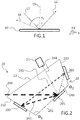
- the Figure 2 schematically represents a spectrometer 20 according to the invention.
- the spectral dispersion means 22 comprise at least three diffraction gratings in reflection. On the Figure 2 the example of three reflection diffraction gratings 201, 202, 203 is shown.
- the reflection diffraction gratings 201, 202, 203 are each aligned on one side 231, 232, respectively 233 of a convex polygon 23.
- the sides 232, 231, 233 are consecutive sides of the polygon 23. They draw together a polygon open. In other words, the convex polygon 23 has more sides than there are diffraction gratings in reflection.
- the diffraction gratings are numbered in the order in which they are reached for the first time by the initial light beam (decomposed into sub-beams as the diffractions, as described below).
- the diffraction gratings 201, 202, 203 are arranged so that a portion of an initial light beam 240 is diffracted in turn once by each of the diffraction gratings, and at least a second time by at least one of the gratings. of diffraction.
- the first diffraction grating 201 receives the initial light beam 240, and returns a first sub-beam 241 corresponding to the diffraction order m 1 of the initial light beam 240 on the first diffraction grating 201 (m 1 is a integer greater than or equal to unity).
- the second diffraction grating 202 receives the first sub-beam 241, and returns a second sub-beam 242 corresponding to the diffraction order m 2 of the first sub-beam 241 on the second diffraction grating 202 (m 2 is an integer greater than or equal to unity).
- the third diffraction grating 203 receives the second sub-beam 242, and returns a third sub-beam 243 corresponding to the diffraction order m 3 of the second sub-beam 242 on the third diffraction grating 203 (m 3 is an integer greater than or equal to unity).
- the first diffraction grating 201 receives the third sub-beam 243, and returns a fourth sub-beam 244 corresponding to the diffraction order m 4 of the third sub-beam 243 on the first diffraction grating 201 (m 4 is an integer greater than or equal to unity).
- the diffraction gratings are arranged so that the optical path followed by said light beam portion directly connects the first diffraction grating to the second diffraction grating, the second diffraction grating to the third diffraction grating, and the third diffraction grating at the first diffraction grating.
- this optical path directly connects the first diffraction grating to the second diffraction grating, then immediately the second grating diffraction at the third diffraction grating, then immediately the third diffraction grating at the first diffraction grating.
- the invention is based on this particular arrangement of diffraction gratings.
- the presence of the photodetector is therefore not necessary to define a new and inventive spectrometer.
- a convex polygon was introduced simply to further define the positioning of the diffraction gratings relative to each other. This positioning can be defined simply by the optical path as described above.
- the position of the diffraction gratings can be adapted to any initial light beam emitted by a light source, so as to verify the condition on the optical path as defined above.
- the fourth sub-beam 244 is directed towards the photodetector 21.
- the fourth sub-beam 244 corresponds to a portion of the initial light beam having been diffracted once by the second and third diffraction gratings 202 and 203, and having been diffracted twice by the first diffraction grating 201.
- the optical path followed by said light beam portion directly connects the first diffraction grating to the second diffraction grating, the second diffraction grating to the third diffraction grating, and then the third diffraction grating to the first diffraction grating. Then, that is to say immediately after this second impact on the first diffraction grating, said optical path does not directly connect the first diffraction grating to the second diffraction grating.
- This feature relates to each of the embodiments of a spectrometer according to the invention. Therefore, the spectrometer 20 according to the invention does not form a resonator. In the same way, the spectrometer 20 according to the invention does not form a closed cavity.
- the diffraction orders m 1 , m 2 , m 3 and m 4 are the same and advantageously take a value less than or equal to 2, preferably 1.
- an initial light beam of diameter d will cover two networks once, and a network twice.
- the initial light beam performs four passes on a network of diffraction.
- the resolving power of the spectrometer 20 is therefore equivalent to that of a spectrometer receiving a light beam of diameter 4d, and therefore comprising a diffraction grating four times larger.
- the initial light beam of diameter d will cover N gratings a first time, and s networks at least a second time, N being an integer greater than or equal to 3 and s an integer greater than or equal to 1.
- ( Ns ) networks are covered once, and s networks are covered at least twice.
- the resolving power of a spectrometer according to the invention is therefore at least equivalent to that of a spectrometer receiving a light beam of diameter ( N + s ) * d , and therefore comprising a diffraction grating ( N + s ) times wider.
- the invention is based on the use of several diffraction gratings, at least one of which is used twice.
- a spectrometer having a high resolving power is obtained using diffraction gratings having a reduced size, and therefore a lower cost.
- the invention is all the more advantageous in that it offers a better accuracy in determining the wavelength than a Fabry-Perot spectrometer, in which there is a spatio-spectral dependence.
- the sub-beams can propagate directly from a diffraction grating to the next, that is to say without passing through an optical such as an at least partially reflective optics.
- the optical path followed by the initial light beam portion corresponding to the sub-beam 244 directly connects a diffraction grating to the next, without intermediate reflection on a spacer mirror.
- the spectrometer according to the invention thus has reduced light intensity losses.
- the initial light beam 240 is incident on the first diffraction grating 201 at a grazing incidence, that is to say with an angle of incidence greater than 60 °.
- the term m * N * ⁇ is advantageously between 1.5 and 1.8.
- boundary conditions are, for example, a central wavelength of the initial light beam (corresponding to a peak intensity of said beam), a line density of the diffraction gratings, a diffraction order to be considered, etc. It can also be posited that the difference between the angle of incidence and the diffraction angle at the order considered has substantially the same absolute value for each diffraction grating (to a few degrees, for example ⁇ 6 °, or ⁇ 2 °, even ⁇ 1 °). This difference can be alternately positive and negative (considering the chronological order of successive incidences on the diffraction gratings).
- the sub-beams 241, 242, 243, 243 and the beam 240 propagate advantageously in the same plane, orthogonal to the direction of the lines of the diffraction gratings 201, 202, 203.
- the Figure 3 illustrates a first embodiment of spectrometer 30 according to the invention.
- the embodiment of the Figure 3 is a special case of the spectrometer illustrated in Figure 2 .
- the spectrometer of the Figure 3 is adapted to receive an incident light beam having a central wavelength of 1053 nm, and incident at an angle of about 61 ° on the first diffraction grating.
- the spectrometer 30 comprises spectral dispersion means formed by three diffraction gratings 302, 301, 303 arranged on consecutive sides of a polygon, advantageously a regular dodecagon.
- the diffraction grating 301 forms a first diffraction grating.
- the network 301 is disposed between a second diffraction grating 302 and a third diffraction grating 303, that is to say flanked laterally by these two other diffraction gratings, as illustrated in FIG. Figure 3 .
- Each of the diffraction gratings has a line density equal to 1740 lines per millimeter.
- the angle formed between the first and second diffraction gratings 301, 302 is equal to the angle formed between the first and third diffraction gratings 301, 303, ie an angle of 150 °.
- a structure having substantially a symmetry with respect to a plane parallel to the lines of the first diffraction grating and passing through the center of this diffraction grating 301 is thus produced.
- the features of the diffraction gratings are parallel to the axis (Oz). and orthogonal to the plane of propagation of the light beams (Oxy).
- each angle may be different and between 148 ° and 152 °.
- the first diffraction grating 301 receives the initial light beam 340 and returns a first sub-beam 341, corresponding to the first diffraction order of the initial light beam on the first diffraction grating.
- the second diffraction grating 302 receives the first sub-beam 341 and returns a second sub-beam 342, corresponding to the first diffraction order of the first sub-beam on the second diffraction grating.
- the third diffraction grating 303 receives the second sub-beam 342 and returns a third sub-beam 343, corresponding to the first diffraction order of the second sub-beam on the third diffraction grating.
- the first diffraction grating 301 receives the third sub-beam 343 and returns a fourth sub-beam 344, corresponding to the first diffraction order of the third sub-beam on the first diffraction grating.
- the fourth sub-beam 344 is received by the photodetector 31.
- the initial light beam 340 is incident on the first diffraction grating 301 at an angle of incidence of 61 °. This angle is measured relative to the normal 352 at the first diffraction grating 301.
- the angle of incidence is chosen close to 60 °, within 2 °. This angle must be different from 60.2 ° to prevent the fourth sub-beam 344 from propagating in the same direction as the specular reflection of the initial light beam 340 on the first diffraction grating 301 (diffraction at order 0) .
- the initial light beam has a maximum intensity at a known central wavelength.
- it is a wavelength in the infrared (advantageously between 1 micron and 2 microns).
- the central wavelength is equal to 1053 nm.
- the spectrometer 30 makes it possible to determine the other spectral components of the initial light beam, close to this central wavelength.
- the measurement range is typically 200 nm. It can thus be seen that the spectrometer according to the invention has a good spectral acceptance, which can reach 200 nm in width.
- the central wavelength is not precisely known, and at least one parameter of the spectrometer according to the invention is adjusted so as to be able to detect on the photodetector 31 a light signal corresponding to a diffracted beam two. once on the network 301 and once on the networks 302 and 303.
- each of the diffraction gratings 301, 302, 303 is mounted on respective pivoting means 311, 312, 313 around the z axis.
- the z axis is parallel to lines or reflective bands of the diffraction gratings 301, 302, 303.
- the orientation of the diffraction gratings of the spectrometer according to the invention is adjusted by pivoting each of the gratings alternately by an angle ⁇ and an angle - ⁇ (the diffraction gratings then being considered in the order in which they are distributed on the consecutive sides of the polygon, here a dodecagon).
- the second and third diffraction gratings 302, 303 are pivoted by an angle ⁇ , and the first diffraction grating 301 is rotated by an angle ⁇ .
- an initial light beam of central wavelength may vary between 1000 nm and 1200 nm.
- the numbering of the diffraction gratings is performed by considering the order in which a part of the incident light beam propagates network network. Nevertheless, for the pivoting of the gratings alternately by an angle ⁇ and an angle - ⁇ , we consider the diffraction gratings in the order in which they are distributed on the consecutive sides of the polygon.
- ⁇ may be provided for producing a wavelength tunable spectrometer, in particular means for translating a diffraction grating in the plane (xOy) orthogonal to the axis (Oz).
- the location of the photodetector 31 relative to the spectral dispersion means can be modified accordingly.
- the photodetector 31 can then be mounted on a mobile stage, so as to receive a desired light beam.
- the photodetector 31 is fixed. We can then provide a movable mirror for moving said desired light beam relative to the photodetector.
- Each diffraction grating receives an incident light beam, and returns a sub-beam corresponding to the first diffraction order of said incident beam on this diffraction grating.
- Guidance or positioning means for a light source to be studied may be provided, adapted to position said source so that the initial light beam has a desired angle of incidence on the first diffraction grating.
- These guide means may be arranged on a movable plate, so as to be able to modify this angle of incidence as a function of the light source.
- the initial light beam is fed to the input of the spectrometer according to the invention by an optical fiber of numerical aperture 0.12. At the output of the optical fiber, a collimation lens is placed.
- the photodetector is advantageously a detector having a surface detection area, two-dimensional.
- An advantage of such a detector is that the spectrum of the incident light beam can be obtained by analysis of a single light pulse.
- spectrometer according to the invention The light beams propagate in planes parallel to the plane (xOy). This technique is called "multiplexing of several measurement channels".
- the photodetector is for example a camera of 2456x2058 pixels, and having a pixel width of 3.45 microns.
- a focusing lens (not shown) is advantageously placed, which makes it possible to transform an angular dispersion by the dispersion means into a lateral displacement on the photodetector.
- the focal length of this focusing lens is determined by taking into account the pixel size of the photodetector, so that this pixel size does not limit the resolving power of the spectrometer according to the invention.
- the photodiode is a photodiode for use with recurrent signals.
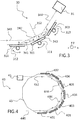
- the Figure 4 schematically represents a second embodiment of spectrometer 40 according to the invention.
- the embodiment of the Figure 4 is a special case of the spectrometer illustrated in Figure 2 .
- the spectrometer of the Figure 4 is adapted to receive an incident light beam having a central wavelength of 1053 nm, and incident at an angle of about 61 ° on the first diffraction grating.
- the spectrometer 40 of the Figure 4 comprises seven diffraction gratings 402, 401, 403, 404, 405, 406 and 407 arranged on consecutive sides of a regular dodecagon 43.
- the diffraction gratings 401, 402, 403 correspond to the diffraction gratings 301, 302, 302 of the spectrometer of the Figure 3 .
- the initial beam 440 corresponds to the initial beam 340 of the Figure 3 .
- the sub-beam 444 corresponds to the sub-beam 344 of the Figure 3 .
- the sub-beam 444 is incident on the fourth diffraction grating 404 with an angle of incidence of 61 °.
- the diffraction gratings 404, 403, 405 we find the geometry corresponding to the diffraction gratings 401, 402, 403.
- the sub-beam 448 is obtained after a first-order diffraction on the networks 403 and 405, and two first-order diffractions on the network 404.
- the sub-beam 448 is incident on the sixth diffraction grating 406 with a incidence angle of 61 °.
- the sub-beam 452 is obtained.
- the sub-beam 452 is directed towards the photodetector 41.
- the diffraction gratings are not aligned on consecutive sides of a regular dodecagon, but parallel to consecutive sides of a regular dodecagon. It will be possible to continue the regular sequence of diffraction gratings following a spiral path.
- each diffraction grating except the diffraction gratings at the ends of the diffraction grating sequence, receives twice the same portion of the initial light beam. If n diffraction gratings, one thus increases the power of resolution, with step of network and beam width identical, of a factor 2 * ( n -1). In other words, at power of equal resolution, the diameter of the initial light beam is divided by a factor 2 * ( n -1).
- a limitation to the number of gratings is the widening of the diffracted beam as it passes over the diffraction gratings. It may also be noted that a focal length of a focusing lens (not shown) for focusing a final sub-beam on the photodetector is also divided by a factor 2 * ( n -1).
- the field of the invention is more particularly that of infrared spectrometry (wavelengths for example between 1000 nm and 2000 nm).
- the sub-beam 444 is directed in the same direction as the specular reflection (diffraction at the 0) order of the initial light beam on the first diffraction grating 401. Then, this specular reflection is diffracted on the fourth diffraction grating 404. The order 0 of this The diffraction propagates in the same direction as the sub-beam 448, and so on until the photodetector 41. At each diffraction, there is an energy loss. Thus, the specular reflection incident on the photodetector, corresponding to successive diffractions in order 0, has a light energy sufficiently low not to disturb the detection by blinding the photodetector.
- a deflector element adapted to deflect a 180 ° light beam by translating it parallel to itself.
- a sub-beam emerging from the spectral dispersion means returns to them. This doubles the number of passages on the diffraction gratings.
- a photo-detector is then available to receive the sub-beam obtained.
- Several deflecting elements can be provided to multiply the number of passages on the spectral dispersion means by as much.
- the invention is not limited to the examples which have just been described, and it will be possible to envisage numerous variants and embodiments without departing from the scope of the present invention.
- a spiral arrangement of the diffraction gratings, arranged parallel to consecutive sides of a convex polygon can be realized whatever the other parameters of the spectrometer according to the invention.
- the initial light beam can be emitted continuously, or pulse, typically a single pulse.
Description
La présente invention concerne le domaine de la spectrométrie, c'est-à-dire la décomposition spectrale d'un faisceau lumineux et la détection des composantes spectrales ainsi isolées les unes des autres.The present invention relates to the field of spectrometry, that is to say the spectral decomposition of a light beam and the detection of the spectral components thus isolated from each other.
L'invention concerne un spectromètre, c'est-à-dire un dispositif de spectrométrie comprenant des moyens de dispersion spectrale d'un faisceau lumineux, et un photo-détecteur pour mesurer une intensité lumineuse reçue après décomposition spectrale. On relie un emplacement d'une tâche lumineuse dans le plan du photo-détecteur, et une longueur d'onde, à l'aide d'un étalonnage en longueur d'onde. Pour cela, on utilise le spectromètre avec une source lumineuse de spectre connu (par exemple une lampe au mercure ou au tungstène), et on relève les emplacements des tâches lumineuses obtenues.The invention relates to a spectrometer, that is to say a spectrometer device comprising means for spectrally dispersing a light beam, and a photodetector for measuring a light intensity received after spectral decomposition. A location of a light spot is connected to the photodetector plane, and a wavelength, using a wavelength calibration. For this purpose, the spectrometer is used with a light source of known spectrum (for example a mercury or tungsten lamp), and the locations of the light spots obtained are noted.
Le photo-détecteur peut recevoir simultanément plusieurs composantes spectrales du faisceau lumineux, de façon à mesurer simultanément une intensité lumineuse en fonction de la longueur d'onde. On utilise alors typiquement une caméra.The photodetector can simultaneously receive several spectral components of the light beam, so as to simultaneously measure a light intensity as a function of the wavelength. A camera is then typically used.
En variante, le photo-détecteur présente une surface réduite, et on déplace un faisceau lumineux incident relativement à ce photo-détecteur de façon à tracer point par point un spectre du faisceau lumineux incident, correspondant à l'intensité lumineuse en fonction de la longueur d'onde. On utilise alors typiquement une photodiode.As a variant, the photo-detector has a reduced surface, and an incident light beam is displaced relative to this photo-detector so as to draw point by point a spectrum of the incident light beam, corresponding to the light intensity as a function of the length. wave. A photodiode is then typically used.
Dans tout le texte, le terme « spectrométrie » désignera toute technique de décomposition spectrale, et détection d'au moins une composante spectrale ainsi isolée. Notamment, on englobera sous ce terme non seulement la spectrographie, c'est-à-dire la détection simultanée de plusieurs composantes spectrales isolées spatialement, mais également des techniques de détections consécutives de ces plusieurs composantes spectrales, par déplacement d'un faisceau lumineux relativement à un détecteur.Throughout the text, the term "spectrometry" denotes any technique of spectral decomposition, and detection of at least one spectral component thus isolated. Notably, this term will include not only spectrography, ie the simultaneous detection of several spectrally isolated spectral components, but also techniques of consecutive detections of these several spectral components, by displacement of a light beam relative to a detector.
Les moyens de dispersion spectrale peuvent comprendre un réseau de diffraction.The spectral dispersion means may comprise a diffraction grating.
On a représenté sur la
Un faisceau lumineux 11 est incident sur le réseau de diffraction 10. Il forme un angle i avec la normale 13 au plan du réseau 10. Le faisceau lumineux 11 est monochromatique, de longueur d'onde λ0. Il est renvoyé par le réseau de diffraction sous la forme de plusieurs sous-faisceaux :
- un sous-faisceau spéculaire 12, correspondant à une diffraction d'ordre 0 ou en d'autres termes à une réflexion spéculaire ;
- un sous-
faisceau 14, formant un angle r1 avec lanormale 13 au plan duréseau 10, et correspondant à une diffraction d'ordre 1.
- a
specular sub-beam 12, corresponding to a diffraction of order 0 or in other words to a specular reflection; - a
sub-beam 14, forming an angle r 1 with the normal 13 to the plane of thenetwork 10, and corresponding to a diffraction oforder 1.
Pour des raisons de lisibilité de la figure, on n'a pas représenté les ordres de diffraction supérieurs à l'ordre 1.For the sake of legibility of the figure, the diffraction orders greater than the
Dans tout le texte, on nomme « réflexion spéculaire » la diffraction à l'ordre 0.Throughout the text, the term "specular reflection" is used to describe the diffraction at order 0.
L'angle rm est déterminé par la loi des réseaux pour un réseau de diffraction en réflexion : ![]()
- i l'angle formé entre le faisceau
lumineux incident 11 et lanormale 13 au plan duréseau 10 ; - rm l'angle formé entre le sous-faisceau correspondant à la diffraction d'ordre m, et la
normale 13 au plan duréseau 10. On appelle également « faisceau lumineux diffracté à l'ordre m », le sous-faisceau correspondant à la diffraction d'ordre m ; - λ la longueur d'onde du faisceau lumineux diffracté d'ordre m ;
- N la densité de traits du
réseau 10 ; et - m l'ordre de diffraction considéré.
- the angle formed between the
incident light beam 11 and the normal 13 at the plane of thegrating 10; - rm the angle formed between the sub-beam corresponding to the diffraction order m, and the normal 13 to the plane of the
network 10. Also called "light beam diffracted order m", the sub-beam corresponding to the diffraction of order m; - λ the wavelength of the diffracted light beam of order m;
- N the line density of the
network 10; and - m the order of diffraction considered.
On voit que l'angle rm dépend de la longueur d'onde. Ainsi, le réseau de diffraction 10 permet de séparer spatialement différentes contributions spectrales d'un faisceau lumineux incident.We see that the angle rm depends on the wavelength. Thus, the diffraction grating 10 makes it possible to spatially separate different spectral contributions from an incident light beam.
Un avantage des spectromètres comprenant un réseau de diffraction est qu'ils présentent une plage spectrale de mesure très importante, contrairement à d'autres types d'interféromètres tels que les interféromètres Fabry-Pérot ne pouvant analyser qu'une plage très étroite de longueurs d'onde.An advantage of spectrometers comprising a diffraction grating is that they have a very large spectral range of measurement, unlike other types of interferometers such as Fabry-Perot interferometers that can only analyze a very narrow range of lengths. 'wave.
L'inconvénient des spectromètres à réseau est cependant leur pouvoir de résolution très limité. En d'autres termes, leurs capacités de séparation spatiale des différentes longueurs d'onde sont limitées. On nomme « résolution » d'un spectromètre la plus petite différence de longueurs d'onde qu'il permet de distinguer. Le pouvoir de résolution d'un spectromètre est le rapport d'une longueur d'onde centrale sur la résolution correspondante. Ainsi, une valeur élevée du pouvoir de résolution correspond à une grande qualité du spectromètre. On montre que le pouvoir de résolution d'un réseau de diffraction dépend du nombre de traits éclairés par le faisceau lumineux incident. Par exemple, on peut distinguer des largeurs de raie d'environ 30 GHz pour une longueur d'onde de 1 µm avec un réseau de diffraction de 1200 traits/mm éclairé par un faisceau lumineux de 30 mm de diamètre.The disadvantage of network spectrometers is, however, their very limited resolution power. In other words, their spatial separation capabilities of different wavelengths are limited. The term "resolution" of a spectrometer is the smallest difference in wavelengths that can be distinguished. The resolving power of a spectrometer is the ratio of a central wavelength to the corresponding resolution. Thus, a high value of resolving power corresponds to a high quality of the spectrometer. It is shown that the resolving power of a diffraction grating depends on the number of lines illuminated by the incident light beam. For example, one can distinguish line widths of about 30 GHz for a wavelength of 1 micron with a diffraction grating of 1200 lines / mm illuminated by a light beam of 30 mm in diameter.
On voit donc qu'une solution pour réaliser un spectromètre à réseau présentant un pouvoir de résolution élevé, consiste à augmenter la largeur du faisceau lumineux incident, et par conséquent les dimensions du réseau de diffraction. Un inconvénient de cette solution est que le coût d'un réseau de diffraction augmente avec sa taille.It can therefore be seen that a solution for producing a high-resolution network spectrometer consists in increasing the width of the incident light beam, and consequently the dimensions of the diffraction grating. A disadvantage of this solution is that the cost of a diffraction grating increases with its size.
On connaît dans l'art antérieur le document
Un inconvénient d'un tel spectromètre est que la portion du faisceau incident, diffractée plusieurs fois par le même réseau de diffraction, présente une intensité lumineuse très faible du fait de ses passages par le miroir partiellement réfléchissant.A disadvantage of such a spectrometer is that the portion of the incident beam, diffracted several times by the same diffraction grating, has a very low light intensity due to its passage through the partially reflecting mirror.
On connaît aussi le document
Un objectif de la présente invention est de proposer un spectromètre à réseau de diffraction qui ne présente pas au moins l'un des inconvénients de l'art antérieur.An object of the present invention is to provide a diffraction grating spectrometer which does not have at least one of the drawbacks of the prior art.
En particulier, un but de la présente invention est de proposer un spectromètre à réseau de diffraction présentant un grand pouvoir de résolution, pour un coût réduit.In particular, an object of the present invention is to provide a diffraction grating spectrometer having a high resolving power, at a reduced cost.
Un autre but de la présente invention est de proposer un spectromètre à réseau de diffraction présentant des pertes d'intensité lumineuse réduites.Another object of the present invention is to provide a diffraction grating spectrometer having reduced light intensity losses.
Cet objectif est atteint avec un spectromètre comprenant des moyens de dispersion spectrale d'un faisceau lumineux initial tel que défini dans la revendication 1. Selon l'invention, les moyens de dispersion spectrale comprennent au moins trois réseaux de diffraction en réflexion, disposés de sorte qu'une portion du faisceau lumineux initial est diffractée tour à tour par chacun des réseaux de diffraction et est diffractée au moins une deuxième fois par au moins un des réseaux de diffraction.This objective is achieved with a spectrometer comprising spectral dispersion means of an initial light beam as defined in
Le spectromètre selon l'invention comprend avantageusement un photo-détecteur, pour mesurer l'intensité lumineuse d'un faisceau lumineux incident.The spectrometer according to the invention advantageously comprises a photodetector for measuring the light intensity of an incident light beam.
Ladite portion du faisceau lumineux initial forme alors le faisceau lumineux incident sur le photo-détecteur.Said portion of the initial light beam then forms the light beam incident on the photodetector.
On peut considérer que les réseaux de diffraction en réflexion sont parallèles à des côtés consécutifs d'un polygone convexe.It can be considered that the diffraction gratings in reflection are parallel to consecutive sides of a convex polygon.
On considère la projection orthogonale des réseaux de diffraction dans un plan, le polygone convexe étant défini dans ce plan. Il s'agit avantageusement du plan de propagation de ladite portion du faisceau lumineux initial, les réseaux de diffraction étant disposés orthogonaux à ce plan. En d'autres termes, les réseaux de diffraction présentent de préférence des traits parallèles entre eux, et orthogonaux à un plan dans lequel on définit ledit polygone convexe.We consider the orthogonal projection of the diffraction gratings in a plane, the convex polygon being defined in this plane. It is advantageously the plane of propagation of said portion of the initial light beam, the diffraction gratings being arranged orthogonal to this plane. In other words, the diffraction gratings preferably have parallel lines between them, and orthogonal to a plane in which said convex polygon is defined.
De préférence, les réseaux de diffraction en réflexion sont alignés sur les côtés consécutifs du polygone convexe. En d'autres termes, chaque réseau de diffraction n'est pas seulement parallèle à un côté de polygone, mais confondu avec au moins une partie de ce côté de polygone.Preferably, the diffraction gratings in reflection are aligned on the consecutive sides of the convex polygon. In other words, each diffraction grating is not only parallel to a polygon side, but coincides with at least a part of that polygon side.
Selon un mode de réalisation avantageux, un premier réseau de diffraction est disposé entre un deuxième réseau de diffraction et un troisième réseau de diffraction.According to an advantageous embodiment, a first diffraction grating is disposed between a second diffraction grating and a third diffraction grating.
De préférence, les premier, deuxième et troisième réseaux de diffraction sont disposés de sorte que :
- le premier réseau de diffraction reçoit un premier faisceau lumineux et renvoie un premier sous-faisceau, correspondant à la diffraction d'ordre m1 du premier faisceau lumineux sur le premier réseau de diffraction, avec m1 entier supérieur ou égal à l'unité ;
- le deuxième réseau de diffraction reçoit le premier sous-faisceau et renvoie un deuxième sous-faisceau, correspondant à la diffraction d'ordre m2 du premier sous-faisceau sur le deuxième réseau de diffraction, avec m2 entier supérieur ou égal à l'unité ;
- le troisième réseau de diffraction reçoit le deuxième sous-faisceau et renvoie un troisième sous-faisceau, correspondant à la diffraction d'ordre m3 du deuxième sous-faisceau sur le troisième réseau de diffraction, avec m3 entier supérieur ou égal à l'unité ; et
- le premier réseau de diffraction reçoit le troisième sous-faisceau et renvoie un quatrième sous-faisceau, correspondant à la diffraction d'ordre m4 du troisième sous-faisceau sur le premier réseau de diffraction, avec m4 entier supérieur ou égal à l'unité.
- the first diffraction grating receives a first light beam and returns a first sub-beam, corresponding to the diffraction of order m 1 of the first light beam on the first diffraction grating, with m 1 integer greater than or equal to unity;
- the second diffraction grating receives the first sub-beam and returns a second sub-beam, corresponding to the diffraction of order m 2 of the first sub-beam on the second diffraction grating, with m 2 integer greater than or equal to unit;
- the third diffraction grating receives the second sub-beam and returns a third sub-beam, corresponding to the diffraction of order m 3 of the second sub-beam on the third diffraction grating, with m 3 integer greater than or equal to unit; and
- the first diffraction grating receives the third sub-beam and returns a fourth sub-beam, corresponding to the diffraction of order m 4 of the third sub-beam on the first diffraction grating, with m 4 integer greater than or equal to unit.
De préférence, les ordres m1, m2, m3, et m4 sont égaux.Preferably, the orders m 1 , m 2 , m 3 , and m 4 are equal.
Les ordres m1, m2, m3, et m4 sont avantageusement égaux à l'unité.The orders m 1 , m 2 , m 3 , and m 4 are advantageously equal to unity.
Un angle entre les premier et deuxième réseaux de diffraction peut être égal à un angle entre les premier et troisième réseaux de diffraction.An angle between the first and second diffraction gratings may be equal to an angle between the first and third diffraction gratings.
Les réseaux de diffraction sont avantageusement alignés sur des côtés consécutifs d'un polygone régulier.The diffraction gratings are advantageously aligned on consecutive sides of a regular polygon.
Les réseaux de diffraction peuvent être disposés de façon à ce que :
- chaque réseau de diffraction reçoive un faisceau lumineux incident, et renvoie un sous-faisceau correspondant à la diffraction d'ordre mi du faisceau lumineux incident sur ledit réseau de diffraction, avec mi entier supérieur ou égal à l'unité ;
- une valeur absolue d'une différence entre un angle d'incidence du faisceau lumineux incident sur le réseau de diffraction, et un angle médian du sous-faisceau relativement audit réseau de diffraction, soit la même à plus ou moins six degrés près pour chaque réseau de diffraction.
- each diffraction grating receives an incident light beam, and returns a sub-beam corresponding to the diffraction of order m i of the light beam incident on said diffraction grating, with m i integer greater than or equal to unity;
- an absolute value of a difference between an incidence angle of the light beam incident on the diffraction grating, and a median angle of the sub-beam relative to said diffraction grating, the same to within plus or minus six degrees for each grating of diffraction.
Un chemin optique suivi par ladite portion du faisceau lumineux initial peut relier directement un réseau de diffraction au suivant.An optical path followed by said portion of the initial light beam can directly connect a diffraction grating to the next.
De préférence, chaque réseau de diffraction présente des rayures réfléchissantes parallèles à un axe de référence, et est monté sur des moyens de pivotement autour de l'axe de référence.Preferably, each diffraction grating has reflective stripes parallel to a reference axis, and is mounted on pivoting means about the reference axis.
Chacun des réseaux de diffraction peut présenter un même pas de réseau.Each of the diffraction gratings may have the same network pitch.
Un angle entre deux réseaux de diffraction consécutifs est avantageusement compris entre 140 ° et 160 °, chaque réseau de diffraction présentant une densité de traits égale à 1740 traits par millimètre.An angle between two consecutive diffraction gratings is advantageously between 140 ° and 160 °, each diffraction grating having a line density equal to 1740 lines per millimeter.
L'invention concerne également un procédé d'utilisation d'un spectromètre selon l'invention, selon lequel on adapte ledit spectromètre à une longueur d'onde centrale du faisceau lumineux incident en pivotant chacun des réseaux de diffraction alternativement d'un angle θ et d'un angle -θ.The invention also relates to a method of using a spectrometer according to the invention, according to which said spectrometer is adapted to a central wavelength of the incident light beam by pivoting each of the diffraction gratings alternately at an angle θ and an angle -θ.
La présente invention sera mieux comprise à la lecture de la description d'exemples de réalisation donnés à titre purement indicatif et nullement limitatif, en faisant référence aux dessins annexés sur lesquels :
- la
Figure 1 illustre un réseau de diffraction en réflexion ; - la
Figure 2 illustre de façon schématique un spectromètre selon l'invention ; - la
Figure 3 illustre un premier mode de réalisation de spectromètre selon l'invention ; et - la
Figure 4 illustre un deuxième mode de réalisation de spectromètre selon l'invention.
- the
Figure 1 illustrates a diffraction grating in reflection; - the
Figure 2 schematically illustrates a spectrometer according to the invention; - the
Figure 3 illustrates a first embodiment of the spectrometer according to the invention; and - the
Figure 4 illustrates a second embodiment of the spectrometer according to the invention.
La
Le spectromètre 20 comprend :
- un photo-
détecteur 21 tel que décrit en introduction, pour mesurer l'intensité lumineuse d'un faisceau incident ; et - des moyens de dispersion spectrale 22 selon l'invention.
- a
photodetector 21 as described in the introduction, for measuring the light intensity of an incident beam; and - spectral dispersion means 22 according to the invention.
Les moyens de dispersion spectrale 22 comprennent au moins trois réseaux de diffraction en réflexion. Sur la
Les réseaux de diffraction en réflexion 201, 202, 203 sont chacun alignés sur un côté 231, 232, respectivement 233 d'un polygone convexe 23. Les côtés 232, 231, 233 sont des côtés consécutifs du polygone 23. Ils dessinent ensemble un polygone ouvert. En d'autres termes, le polygone convexe 23 présente plus de côtés qu'il y a de réseaux de diffraction en réflexion.The
Dans tout le texte, les réseaux de diffraction sont numérotés dans l'ordre selon lequel ils sont atteints pour la première fois par le faisceau lumineux initial (décomposé en sous-faisceaux au fur et à mesure des diffractions, comme décrit dans la suite).Throughout the text, the diffraction gratings are numbered in the order in which they are reached for the first time by the initial light beam (decomposed into sub-beams as the diffractions, as described below).
Les réseaux de diffraction 201, 202, 203 sont disposés de sorte qu'une portion d'un faisceau lumineux initial 240 est diffractée tour à tour une fois par chacun des réseaux de diffraction, et au moins une deuxième fois par au moins un des réseaux de diffraction.The
En particulier, le premier réseau de diffraction 201 reçoit le faisceau lumineux initial 240, et renvoie un premier sous-faisceau 241 correspondant à l'ordre de diffraction m1 du faisceau lumineux initial 240 sur le premier réseau de diffraction 201 (m1 est un entier supérieur ou égal à l'unité).In particular, the
Le deuxième réseau de diffraction 202 reçoit le premier sous-faisceau 241, et renvoie un deuxième sous-faisceau 242 correspondant à l'ordre de diffraction m2 du premier sous-faisceau 241 sur le deuxième réseau de diffraction 202 (m2 est un entier supérieur ou égal à l'unité).The
Le troisième réseau de diffraction 203 reçoit le deuxième sous-faisceau 242, et renvoie un troisième sous-faisceau 243 correspondant à l'ordre de diffraction m3 du deuxième sous-faisceau 242 sur le troisième réseau de diffraction 203 (m3 est un entier supérieur ou égal à l'unité).The
Le premier réseau de diffraction 201 reçoit le troisième sous-faisceau 243, et renvoie un quatrième sous-faisceau 244 correspondant à l'ordre de diffraction m4 du troisième sous-faisceau 243 sur le premier réseau de diffraction 201 (m4 est un entier supérieur ou égal à l'unité).The
Ainsi, selon l'invention, les réseaux de diffraction sont agencés de sorte que le chemin optique suivi par ladite portion de faisceau lumineux relie directement le premier réseau de diffraction au deuxième réseau de diffraction, le deuxième réseau de diffraction au troisième réseau de diffraction, et le troisième réseau de diffraction au premier réseau de diffraction.Thus, according to the invention, the diffraction gratings are arranged so that the optical path followed by said light beam portion directly connects the first diffraction grating to the second diffraction grating, the second diffraction grating to the third diffraction grating, and the third diffraction grating at the first diffraction grating.
En d'autres termes, ce chemin optique relie directement le premier réseau de diffraction au deuxième réseau de diffraction, puis immédiatement le deuxième réseau de diffraction au troisième réseau de diffraction, puis immédiatement le troisième réseau de diffraction au premier réseau de diffraction.In other words, this optical path directly connects the first diffraction grating to the second diffraction grating, then immediately the second grating diffraction at the third diffraction grating, then immediately the third diffraction grating at the first diffraction grating.
L'invention repose sur cet agencement particulier des réseaux de diffraction. La présence du photo-détecteur n'est donc pas nécessaire pour définir un spectromètre nouveau et inventif.The invention is based on this particular arrangement of diffraction gratings. The presence of the photodetector is therefore not necessary to define a new and inventive spectrometer.
On a introduit un polygone convexe simplement pour préciser plus avant le positionnement des réseaux de diffraction les uns relativement aux autres. Ce positionnement peut être défini simplement par le chemin optique tel que décrit ci-dessus.A convex polygon was introduced simply to further define the positioning of the diffraction gratings relative to each other. This positioning can be defined simply by the optical path as described above.
La position des réseaux de diffraction peut être adaptée à n'importe quel faisceau lumineux initial émis par une source lumineuse, de façon à vérifier la condition sur le chemin optique telle que définie ci-dessus.The position of the diffraction gratings can be adapted to any initial light beam emitted by a light source, so as to verify the condition on the optical path as defined above.
Le quatrième sous-faisceau 244 est dirigé vers le photo-détecteur 21.The
Le quatrième sous-faisceau 244 correspond à une portion du faisceau lumineux initial ayant été diffractée une fois par les deuxième et troisième réseaux de diffraction 202 et 203, et ayant été diffractée deux fois par le premier réseau de diffraction 201.The
Ainsi, le chemin optique suivi par ladite portion de faisceau lumineux relie directement le premier réseau de diffraction au deuxième réseau de diffraction, le deuxième réseau de diffraction au troisième réseau de diffraction, puis le troisième réseau de diffraction au premier réseau de diffraction. Ensuite, c'est-à-dire immédiatement après cette deuxième incidence sur le premier réseau de diffraction, ledit chemin optique ne relie pas directement le premier réseau de diffraction au deuxième réseau de diffraction. Cette particularité concerne chacun des modes de réalisation d'un spectromètre selon l'invention. Par conséquent, le spectromètre 20 selon l'invention ne forme pas un résonateur. De la même façon, le spectromètre 20 selon l'invention ne forme pas une cavité fermée.Thus, the optical path followed by said light beam portion directly connects the first diffraction grating to the second diffraction grating, the second diffraction grating to the third diffraction grating, and then the third diffraction grating to the first diffraction grating. Then, that is to say immediately after this second impact on the first diffraction grating, said optical path does not directly connect the first diffraction grating to the second diffraction grating. This feature relates to each of the embodiments of a spectrometer according to the invention. Therefore, the
De préférence, les ordres de diffraction m1, m2, m3 et m4 sont les mêmes et prennent avantageusement une valeur inférieure ou égale à 2, de préférence 1.Preferably, the diffraction orders m 1 , m 2 , m 3 and m 4 are the same and advantageously take a value less than or equal to 2, preferably 1.
Ainsi, un faisceau lumineux initial de diamètre d va couvrir deux réseaux une fois, et un réseau deux fois. Le faisceau lumineux initial effectue quatre passages sur un réseau de diffraction. En supposant que les pas des réseaux sont tous identiques, le pouvoir de résolution du spectromètre 20 est donc équivalent à celui d'un spectromètre recevant un faisceau lumineux de diamètre 4d, et comprenant par conséquent un réseau de diffraction quatre fois plus large. De façon générale, le faisceau lumineux initial de diamètre d va couvrir N réseaux une première fois, et s réseaux au moins une deuxième fois, N étant un entier supérieur ou égal à 3 et s un entier supérieur ou égal à 1. En d'autres termes, (N-s) réseaux sont couverts une fois, et s réseaux sont couverts au moins deux fois. Le pouvoir de résolution d'un spectromètre selon l'invention est donc au moins équivalent à celui d'un spectromètre recevant un faisceau lumineux de diamètre (N+s)*d, et comprenant par conséquent un réseau de diffraction (N+s) fois plus large.Thus, an initial light beam of diameter d will cover two networks once, and a network twice. The initial light beam performs four passes on a network of diffraction. Assuming that the steps of the networks are all identical, the resolving power of the
L'invention est basée sur l'utilisation de plusieurs réseaux de diffraction dont l'un au moins est utilisé deux fois.The invention is based on the use of several diffraction gratings, at least one of which is used twice.
Elle n'est pas basée sur l'utilisation d'un réseau de diffraction de grande taille. Grâce à l'invention, on obtient un spectromètre présentant un fort pouvoir de résolution à l'aide de réseaux de diffraction présentant une taille réduite, donc un coût moindre. On réalise ainsi un spectromètre présentant un coût et un encombrement réduits. En outre, il n'est pas nécessaire d'avoir recours à des optiques de mise en forme d'un faisceau lumineux émis par une source à étudier, afin d'obtenir une grande largeur de faisceau. Cela contribue à diminuer le coût et l'encombrement du spectromètre selon l'invention.It is not based on the use of a large diffraction grating. Thanks to the invention, a spectrometer having a high resolving power is obtained using diffraction gratings having a reduced size, and therefore a lower cost. This produces a spectrometer with reduced cost and space. In addition, it is not necessary to use optical shaping a light beam emitted by a source to be studied, in order to obtain a large beam width. This contributes to reducing the cost and the bulk of the spectrometer according to the invention.
On peut notamment obtenir un pouvoir de résolution du même ordre que ceux pouvant être obtenus par méthode interférométrique, par exemple à l'aide d'un spectromètre de type Fabry-Pérot ou Fizeau. L'invention est d'autant plus avantageuse qu'elle offre une meilleure précision de détermination de la longueur d'onde qu'un spectromètre de type Fabry-Pérot, dans lequel il existe une dépendance spatio-spectrale.In particular, it is possible to obtain a resolving power of the same order as those obtainable by interferometric method, for example by means of a Fabry-Perot or Fizeau type spectrometer. The invention is all the more advantageous in that it offers a better accuracy in determining the wavelength than a Fabry-Perot spectrometer, in which there is a spatio-spectral dependence.
On voit en outre que les sous-faisceaux peuvent se propager directement d'un réseau de diffraction au suivant, c'est-à-dire sans passer par une optique telle qu'une optique au moins partiellement réfléchissante. En d'autres termes, le chemin optique suivi par la portion de faisceau lumineux initial correspondant au sous-faisceau 244, relie directement un réseau de diffraction au suivant, sans réflexion intermédiaire sur un miroir intercalaire. Il n'y a donc pas de pertes énergétiques par absorption dans une optique située entre les réseaux de diffraction, ou par transmission ou réflexion seulement partielle d'un faisceau entre deux passages sur un réseau de diffraction. Le spectromètre selon l'invention présente donc des pertes d'intensité lumineuse réduites. On peut ainsi l'utiliser pour étudier le spectre d'un faisceau lumineux initial de faible intensité lumineuse, sans qu'il soit nécessaire de recourir en sortie à un photo-détecteur particulièrement sensible. En outre, l'absence d'optiques supplémentaires entre les réseaux de diffraction contribue à diminuer le coût et l'encombrement du spectromètre selon l'invention.It is further seen that the sub-beams can propagate directly from a diffraction grating to the next, that is to say without passing through an optical such as an at least partially reflective optics. In other words, the optical path followed by the initial light beam portion corresponding to the sub-beam 244, directly connects a diffraction grating to the next, without intermediate reflection on a spacer mirror. There is therefore no energy loss by absorption in a optically located between the diffraction gratings, or by only partially transmitting or reflecting a beam between two passages on a diffraction grating. The spectrometer according to the invention thus has reduced light intensity losses. It can thus be used to study the spectrum of an initial light beam of low light intensity, without the need to resort to an output at a particularly sensitive photodetector. In addition, the absence of additional optics between the diffraction gratings contributes to reducing the cost and bulk of the spectrometer according to the invention.
Il n'est pas non plus nécessaire de positionner les réseaux en phase, ce qui facilite l'ajustement des positions de chacun des réseaux de diffraction du spectromètre selon l'invention.It is also not necessary to position the networks in phase, which facilitates the adjustment of the positions of each of the diffraction gratings of the spectrometer according to the invention.
Avantageusement, le faisceau lumineux initial 240 est incident sur le premier réseau de diffraction 201 selon une incidence rasante, c'est-à-dire avec un angle d'incidence supérieur à 60°. En d'autres termes, dans la formule (1) présentée en introduction, le terme m*N*λ est avantageusement compris entre 1,5 et 1,8.Advantageously, the
L'homme du métier saura aisément déterminer diverses géométries d'un spectromètre selon l'invention, permettant d'obtenir un premier passage sur chacun des réseaux de diffraction, et au moins un deuxième passage sur l'un d'eux. Il lui suffira pour cela de :
- résoudre un système d'équations basé sur la loi des réseaux (voir équation (1)) s'appliquant pour chaque passage sur un réseau de diffraction ; et
- considérer plusieurs conditions aux limites.
- solve a system of equations based on the law of the networks (see equation (1)) applying for each passage on a diffraction grating; and
- consider several boundary conditions.
Ces conditions aux limites sont par exemple une longueur d'onde centrale du faisceau lumineux initial (correspondant à un pic d'intensité dudit faisceau), une densité de traits des réseaux de diffraction, un ordre de diffraction à considérer, etc. On peut également poser comme condition que la différence entre l'angle d'incidence et l'angle de diffraction à l'ordre considéré présente sensiblement la même valeur absolue pour chaque réseau de diffraction (à quelques degrés près, par exemple ± 6°, ou ± 2°, voire ± 1°). Cette différence peut être alternativement positive et négative (en considérant l'ordre chronologique des incidences successives sur les réseaux de diffraction).These boundary conditions are, for example, a central wavelength of the initial light beam (corresponding to a peak intensity of said beam), a line density of the diffraction gratings, a diffraction order to be considered, etc. It can also be posited that the difference between the angle of incidence and the diffraction angle at the order considered has substantially the same absolute value for each diffraction grating (to a few degrees, for example ± 6 °, or ± 2 °, even ± 1 °). This difference can be alternately positive and negative (considering the chronological order of successive incidences on the diffraction gratings).
Par exemple, on réalise un spectromètre selon l'invention, adapté à un faisceau lumineux initial de longueur d'onde centrale 632 nm, ledit faisceau arrivant sur le premier réseau de diffraction avec un angle d'incidence égal à 40°. L'ordre de diffraction considéré est le deuxième ordre de diffraction. Un tel spectromètre présente les caractéristiques suivantes :
- trois réseaux de diffraction présentant tous une densité de traits égale à 1200 traits par millimètre ;
- un angle α1 entre les premier et deuxième réseaux de diffraction égal à 124° ; et
- un angle α2 entre les premier et troisième réseaux de diffraction égal à 130,7°.
- three diffraction gratings all having a line density equal to 1200 lines per millimeter;
- an angle α 1 between the first and second diffraction gratings equal to 124 °; and
- an angle α 2 between the first and third diffraction gratings equal to 130.7 °.
Ainsi, le faisceau lumineux incident 240 arrive sur le premier réseau de diffraction 201 selon un angle d'incidence i1=40°, et un premier sous-faisceau 241 repart selon un angle de diffraction au deuxième ordre r2-1=61°.Thus, the
Le premier sous-faisceau 241 arrive sur le deuxième réseau de diffraction 202 selon un angle d'incidence i2=63°, et un deuxième sous-faisceau 242 repart selon un angle de diffraction au deuxième ordre r2-2=38,7°.The
Le deuxième sous-faisceau 242 arrive sur le troisième réseau de diffraction 203 selon un angle d'incidence i3=36°, et un troisième sous-faisceau 243 repart selon un angle de diffraction au deuxième ordre r2-3=68,3°.The
Le troisième sous-faisceau 243 arrive sur le premier réseau de diffraction 201 selon un angle d'incidence i4=62,4°, et un quatrième sous-faisceau 244 repart selon un angle de diffraction au deuxième ordre r2-4=39°.The
Les sous-faisceaux 241, 242, 243, 243 et le faisceau 240 se propagent avantageusement dans un même plan, orthogonal à la direction des traits des réseaux de diffraction 201, 202, 203.The sub-beams 241, 242, 243, 243 and the
La
Sur la
Le réseau de diffraction 301 forme un premier réseau de diffraction. Le réseau 301 est disposé entre un deuxième réseau de diffraction 302 et un troisième réseau de diffraction 303, c'est-à-dire encadré latéralement par ces deux autres réseaux de diffraction, comme illustré sur la
Chacun des réseaux de diffraction présente une densité de traits égale à 1740 traits par millimètre.Each of the diffraction gratings has a line density equal to 1740 lines per millimeter.
L'angle formé entre les premier et deuxième réseaux de diffraction 301, 302 est égal à l'angle formé entre les premier et troisièmes réseaux de diffraction 301, 303, soit un angle de 150°. On réalise ainsi une structure présentant sensiblement une symétrie par rapport à un plan parallèle aux traits du premier réseau de diffraction et passant par le centre de ce réseau de diffraction 301. Les traits des réseaux de diffraction sont parallèles à l'axe (Oz), et orthogonaux au plan de propagation des faisceaux lumineux (Oxy).The angle formed between the first and
En variante, chaque angle pourra être différent et compris entre 148° et 152°.Alternatively, each angle may be different and between 148 ° and 152 °.
Le premier réseau de diffraction 301 reçoit le faisceau lumineux initial 340 et renvoie un premier sous-faisceau 341, correspondant au premier ordre de diffraction du faisceau lumineux initial sur le premier réseau de diffraction.The
Le deuxième réseau de diffraction 302 reçoit le premier sous-faisceau 341 et renvoie un deuxième sous-faisceau 342, correspondant au premier ordre de diffraction du premier sous-faisceau sur le deuxième réseau de diffraction.The
Le troisième réseau de diffraction 303 reçoit le deuxième sous-faisceau 342 et renvoie un troisième sous-faisceau 343, correspondant au premier ordre de diffraction du deuxième sous-faisceau sur le troisième réseau de diffraction.The
Le premier réseau de diffraction 301 reçoit le troisième sous-faisceau 343 et renvoie un quatrième sous-faisceau 344, correspondant au premier ordre de diffraction du troisième sous-faisceau sur le premier réseau de diffraction.The
Le quatrième sous-faisceau 344 est reçu par le photo-détecteur 31.The
Le faisceau lumineux initial 340 est incident sur le premier réseau de diffraction 301 selon un angle d'incidence de 61°. Cet angle est mesuré relativement à la normale 352 au premier réseau de diffraction 301. L'angle d'incidence est choisi proche de 60°, à 2° près. Cet angle doit être différent de 60,2° pour éviter que le quatrième sous-faisceau 344 ne se propage dans la même direction que la réflexion spéculaire du faisceau lumineux initial 340 sur le premier réseau de diffraction 301 (diffraction à l'ordre 0).The
Selon l'invention, le faisceau lumineux initial présente un maximum d'intensité à une longueur d'onde centrale connue. De préférence, il s'agit d'une longueur d'onde dans l'infrarouge (avantageusement comprise entre 1 µm et 2 µm). Ici, la longueur d'onde centrale est égale à 1053 nm. Le spectromètre 30 permet de déterminer les autres composantes spectrales du faisceau lumineux initial, proches de cette longueur d'onde centrale. La plage de mesure est typiquement de 200 nm. On voit donc que le spectromètre selon l'invention présente une bonne acceptance spectrale, pouvant atteindre 200 nm de largeur.According to the invention, the initial light beam has a maximum intensity at a known central wavelength. Preferably, it is a wavelength in the infrared (advantageously between 1 micron and 2 microns). Here, the central wavelength is equal to 1053 nm. The
En variante, la longueur d'onde centrale n'est pas connue avec précision, et on ajuste au moins un paramètre du spectromètre selon l'invention de façon à pouvoir détecter sur le photo-détecteur 31 un signal lumineux correspondant à un faisceau diffracté deux fois sur le réseau 301 et une fois sur les réseaux 302 et 303. En particulier, on peut modifier un angle d'incidence du faisceau lumineux initial sur le premier réseau de diffraction 301. On peut également modifier séparément l'orientation de chacun des réseaux de diffraction 301, 302, 303.In a variant, the central wavelength is not precisely known, and at least one parameter of the spectrometer according to the invention is adjusted so as to be able to detect on the photodetector 31 a light signal corresponding to a diffracted beam two. once on the
Sur la
En particulier, on ajuste l'orientation des réseaux de diffraction du spectromètre selon l'invention en pivotant chacun des réseaux alternativement d'un angle θ et d'un angle -θ (les réseaux de diffraction étant alors considérés dans l'ordre selon lequel ils sont répartis sur les côtés consécutifs du polygone, ici un dodécagone). Dans l'exemple de la
On pourra prévoir d'autres moyens pour réaliser un spectromètre accordable en longueur d'onde, notamment des moyens de translation d'un réseau de diffraction dans le plan (xOy) orthogonal à l'axe (Oz).Other means may be provided for producing a wavelength tunable spectrometer, in particular means for translating a diffraction grating in the plane (xOy) orthogonal to the axis (Oz).
On peut modifier en conséquence l'emplacement du photo-détecteur 31 relativement aux moyens de dispersions spectrales. Le photo-détecteur 31 peut alors être monté sur une platine mobile, de façon à pouvoir recevoir un faisceau lumineux souhaité.The location of the
Dans une variante préférée, le photo-détecteur 31 est fixe. On peut alors prévoir un miroir mobile pour déplacer ledit faisceau lumineux souhaité relativement au photo-détecteur.In a preferred embodiment, the
Chaque réseau de diffraction reçoit un faisceau lumineux incident, et renvoie un sous-faisceau correspondant au premier ordre de diffraction dudit faisceau incident sur ce réseau de diffraction.Each diffraction grating receives an incident light beam, and returns a sub-beam corresponding to the first diffraction order of said incident beam on this diffraction grating.
On remarque que la géométrie telle que décrite en référence à la
- l'angle d'incidence du faisceau lumineux incident sur un réseau de diffraction ; et
- un angle médian du sous-faisceau relativement audit réseau de diffraction ; est la même (à quelques degrés près, par exemple ±6°, ou ±2°, voire même ±1°), pour chacun des réseaux de diffraction. Ladite différence entre ces deux angles est notée k sur la
Figure 3 . On parle d'angle médian, car les différentes contributions spectrales du faisceau lumineux incident sont séparées spatialement dans le sous-faisceau considéré. L'angle médian correspond à l'angle de diffraction à la longueur d'onde centrale, ici 1053 nm.
- the angle of incidence of the incident light beam on a diffraction grating; and
- a median angle of the sub-beam relative to said diffraction grating; is the same (to a few degrees, for example ± 6 °, or ± 2 °, or even ± 1 °) for each of the diffraction gratings. Said difference between these two angles is noted k on the
Figure 3 . We speak of median angle, because the different spectral contributions of the incident light beam are separated spatially in the sub-beam considered. The median angle corresponds to the diffraction angle at the central wavelength, here 1053 nm.
On pourra prévoir des moyens de guidage ou de positionnement (non représentés) pour une source lumineuse à étudier, adaptés à positionner ladite source de façon à ce que le faisceau lumineux initial présente un angle d'incidence souhaité sur le premier réseau de diffraction. Ces moyens de guidage peuvent être disposés sur une platine mobile, de façon à pouvoir modifier cet angle d'incidence en fonction de la source lumineuse.Guidance or positioning means (not shown) for a light source to be studied may be provided, adapted to position said source so that the initial light beam has a desired angle of incidence on the first diffraction grating. These guide means may be arranged on a movable plate, so as to be able to modify this angle of incidence as a function of the light source.
Selon une variante non représentée, le faisceau lumineux initial est amené en entrée du spectromètre selon l'invention par une fibre optique d'ouverture numérique 0,12. En sortie de la fibre optique, on place une lentille de collimation.According to a variant not shown, the initial light beam is fed to the input of the spectrometer according to the invention by an optical fiber of numerical aperture 0.12. At the output of the optical fiber, a collimation lens is placed.
Le photo-détecteur est avantageusement un détecteur présentant une zone de détection surfacique, à deux dimensions. Un avantage d'un tel détecteur est que l'on peut obtenir le spectre du faisceau lumineux incident par analyse d'une unique impulsion lumineuse. En utilisant l'axe perpendiculaire à l'axe d'étalement des composantes spectrales du faisceau lumineux initial, on peut détecter simultanément des spectres de plusieurs faisceaux lumineux, incidents sur les moyens de dispersion spectrale du spectromètre selon l'invention. Les faisceaux lumineux se propagent dans des plans parallèles au plan (xOy). On nomme cette technique « multiplexage de plusieurs voies de mesure ».The photodetector is advantageously a detector having a surface detection area, two-dimensional. An advantage of such a detector is that the spectrum of the incident light beam can be obtained by analysis of a single light pulse. By using the axis perpendicular to the spreading axis of the spectral components of the initial light beam, it is possible to simultaneously detect spectra of several light beams incident on the spectral dispersion means of the light beam. spectrometer according to the invention. The light beams propagate in planes parallel to the plane (xOy). This technique is called "multiplexing of several measurement channels".
Le photo-détecteur est par exemple une caméra de 2456x2058 pixels, et présentant une largeur de pixel de 3,45 µm. En sortie des moyens de dispersion, on place avantageusement une lentille de focalisation (non représentée) qui permet de transformer une dispersion angulaire par les moyens de dispersion, en un déplacement latéral sur le photo-détecteur. La distance focale de cette lentille de focalisation est déterminée en prenant en compte la taille de pixel du photo-détecteur, de façon à ce que cette taille de pixel ne limite pas le pouvoir de résolution du spectromètre selon l'invention.The photodetector is for example a camera of 2456x2058 pixels, and having a pixel width of 3.45 microns. At the output of the dispersion means, a focusing lens (not shown) is advantageously placed, which makes it possible to transform an angular dispersion by the dispersion means into a lateral displacement on the photodetector. The focal length of this focusing lens is determined by taking into account the pixel size of the photodetector, so that this pixel size does not limit the resolving power of the spectrometer according to the invention.
En variante, le photo-détecteur est une photodiode, pour une utilisation avec des signaux récurrents.Alternatively, the photodiode is a photodiode for use with recurrent signals.
La
Le spectromètre de la
Le spectromètre 40 de la
Les réseaux de diffraction 401, 402, 403 correspondent aux réseaux de diffraction 301, 302, 302 du spectromètre de la
Le sous-faisceau 444 est incident sur le quatrième réseau de diffraction 404 avec un angle d'incidence de 61°. On retrouve, avec les réseaux de diffraction 404, 403, 405 la géométrie correspondant aux réseaux de diffraction 401, 402, 403.The sub-beam 444 is incident on the
Ainsi, après une diffraction au premier ordre sur les réseaux 403 et 405, et deux diffractions au premier ordre sur le réseau 404, on obtient le sous-faisceau 448. Le sous-faisceau 448 est incident sur le sixième réseau de diffraction 406 avec un angle d'incidence de 61°. On retrouve, avec les réseaux de diffraction 406, 405, 407 la géométrie correspondant aux réseaux de diffraction 401, 402, 403.Thus, after a first-order diffraction on the
Après une diffraction au premier ordre sur les réseaux 405 et 407, et deux diffractions au premier ordre sur le réseau 406, on obtient le sous-faisceau 452. Le sous-faisceau 452 est dirigé vers le photo-détecteur 41.After a first-order diffraction on the
On pourrait continuer cet enchaînement régulier de réseaux de diffraction.We could continue this regular sequence of diffraction gratings.
En variante, les réseaux de diffraction ne sont pas alignés sur des côtés consécutifs d'un dodécagone régulier, mais parallèles à des côtés consécutifs d'un dodécagone régulier. On pourra ainsi continuer l'enchaînement régulier de réseaux de diffraction en suivant un tracé en spirale.Alternatively, the diffraction gratings are not aligned on consecutive sides of a regular dodecagon, but parallel to consecutive sides of a regular dodecagon. It will be possible to continue the regular sequence of diffraction gratings following a spiral path.
On voit que chaque réseau de diffraction, excepté les réseaux de diffraction aux extrémités de l'enchaînement de réseaux de diffraction, reçoit deux fois la même portion de faisceau lumineux initial. Soient n réseaux de diffraction, on augmente ainsi le pouvoir de résolution, à pas de réseau et largeur de faisceau identiques, d'un facteur 2*(n-1). En d'autres termes, à pouvoir de résolution égal, on divise le diamètre du faisceau lumineux initial par un facteur 2*(n-1). Une limitation au nombre de réseaux est l'élargissement du faisceau diffracté au fur et à mesure des passages sur les réseaux de diffraction. On peut également remarquer qu'une distance focale d'une lentille de focalisation (non représentée) servant à focaliser un sous-faisceau final sur le photo-détecteur est également divisée par un facteur 2*(n-1).It can be seen that each diffraction grating, except the diffraction gratings at the ends of the diffraction grating sequence, receives twice the same portion of the initial light beam. If n diffraction gratings, one thus increases the power of resolution, with step of network and beam width identical, of a factor 2 * ( n -1). In other words, at power of equal resolution, the diameter of the initial light beam is divided by a factor 2 * ( n -1). A limitation to the number of gratings is the widening of the diffracted beam as it passes over the diffraction gratings. It may also be noted that a focal length of a focusing lens (not shown) for focusing a final sub-beam on the photodetector is also divided by a factor 2 * ( n -1).
Le domaine de l'invention est plus particulièrement celui de la spectrométrie infrarouge (longueurs d'onde comprises par exemple entre 1000 nm et 2000 nm).The field of the invention is more particularly that of infrared spectrometry (wavelengths for example between 1000 nm and 2000 nm).
On voit que comme précédemment, pour un angle d'incidence de 60,2° du faisceau lumineux initial 440 sur le premier réseau de diffraction 401, le sous-faisceau 444 est dirigé selon la même direction que la réflexion spéculaire (diffraction à l'ordre 0) du faisceau lumineux initial sur le premier réseau de diffraction 401. Ensuite, cette réflexion spéculaire est diffractée sur le quatrième réseau de diffraction 404. L'ordre 0 de cette diffraction se propage dans la même direction que le sous-faisceau 448, et ainsi de suite jusqu'au photo-détecteur 41. A chaque diffraction, il y a une perte énergétique. Ainsi, la réflexion spéculaire incidente sur le photo-détecteur, correspondant à des diffractions successives à l'ordre 0, présente une énergie lumineuse suffisamment faible pour ne pas perturber la détection en aveuglant le photo-détecteur.It can be seen that, as previously, for an angle of incidence of 60.2 ° of the
Selon une variante non représentée, on dispose, par exemple à la place du photo-détecteur, un élément déflecteur adapté à dévier un faisceau lumineux de 180° en le translatant parallèlement à lui-même. On peut par exemple utiliser un ou deux prismes en toit. On peut également utiliser deux miroir inclinés à 90° l'un par rapport à l'autre pour former un coin, l'un premier des miroirs recevant un faisceau lumineux avec un angle d'incidence de 45°. Ainsi, un sous-faisceau émergeant des moyens de dispersion spectrale revient vers ces derniers. On double ainsi le nombre des passages sur les réseaux de diffraction. On dispose alors un photo-détecteur de façon à recevoir le sous-faisceau obtenu. On peut prévoir plusieurs éléments déflecteurs, pour multiplier d'autant le nombre de passages sur les moyens de dispersion spectrale.According to a variant not shown, there is, for example instead of the photodetector, a deflector element adapted to deflect a 180 ° light beam by translating it parallel to itself. One can for example use one or two prisms on the roof. It is also possible to use two mirrors inclined at 90 ° with respect to one another to form a wedge, the first of the mirrors receiving a light beam with an angle of incidence of 45 °. Thus, a sub-beam emerging from the spectral dispersion means returns to them. This doubles the number of passages on the diffraction gratings. A photo-detector is then available to receive the sub-beam obtained. Several deflecting elements can be provided to multiply the number of passages on the spectral dispersion means by as much.
On pourra envisager différentes variantes des modes de réalisation des
L'invention n'est pas limitée aux exemples qui viennent d'être décrits, et on pourra envisager de nombreuses variantes et modes de réalisation sans sortir du cadre de la présente invention. Par exemple, on pourra envisager d'autres types de polygones réguliers qu'un dodécagone, par exemple un hexagone. On pourra combiner différentes caractéristiques provenant des différents modes de réalisation, sans sortir du cadre de la présente invention, et dans la mesure où l'effet technique recherché est toujours obtenu. Par exemple, une disposition en spirale des réseaux de diffraction, disposés parallèlement à des côtés consécutifs d'un polygone convexe, pourra être réalisée quels que soient les autres paramètres du spectromètre selon l'invention. Le faisceau lumineux initial pourra être émis en continu, ou par impulsion, typiquement une unique impulsion.The invention is not limited to the examples which have just been described, and it will be possible to envisage numerous variants and embodiments without departing from the scope of the present invention. For example, we can consider other types of regular polygons a dodecagon, for example a hexagon. We can combine different characteristics from different embodiments, without departing from the scope of the present invention, and to the extent that the desired technical effect is always obtained. For example, a spiral arrangement of the diffraction gratings, arranged parallel to consecutive sides of a convex polygon, can be realized whatever the other parameters of the spectrometer according to the invention. The initial light beam can be emitted continuously, or pulse, typically a single pulse.
Claims (13)
- Spectrometer (20; 30; 40) comprising:- spectral dispersion means (22) of an initial light beam (240; 340); and- a photodetector (21; 31; 41), to measure the light intensity of an incident light beam;characterised in that the spectrometer (20; 30; 40) does not constitute a closed cavity, and in that the spectral dispersion means (22) comprise at least three reflective diffraction gratings (201, 202, 203; 301, 302, 303; 401, 402, 403, 404, 405, 406, 407) parallel to consecutive sides of a convex polygon (23; 43), arranged such that:- a portion of the initial light beam (240; 340) is diffracted once by each of the diffraction gratings in turn and is diffracted at least a second time by at least one of the diffraction gratings, this portion of the initial light beam forming the incident light beam on the photodetector; and- the optical path followed by said portion of light beam directly connects a first diffraction grating (201; 301; 401, 404, 406) to a second diffraction grating (202; 302; 402, 403, 405), the second diffraction grating to a third diffraction grating (203; 303; 403, 405, 407), and the third diffraction grating to the first diffraction grating, that is to say without intermediate reflection.
- Spectrometer (20; 30; 40) according to claim 1, characterised in that the reflective diffraction gratings (201, 202, 203; 301, 302, 303; 401, 402, 403, 404, 405, 406, 407) are aligned on the consecutive sides of the convex polygon (23; 43).
- Spectrometer (20; 30; 40) according to claim 1 or 2, characterised in that the first diffraction grating (201; 301; 401,404,406) is arranged between the second diffraction grating (202; 302; 402, 403, 405) and the third diffraction grating (203; 303; 403, 405, 407), along the convex polygon (23; 43), and in that the first, second and third diffraction gratings are arranged such that:- the first diffraction grating (201; 301; 401, 404, 406) receives a first light beam (240; 340; 440, 444, 448) and returns a first sub-beam (241; 341), corresponding to the m1 order diffraction of the first light beam on the first diffraction grating, where m1 is an integer greater than or equal to 1;- the second diffraction grating (202; 302; 402, 403, 405) receives the first sub-beam (241; 341) and returns a second sub-beam (242; 342), corresponding to the m2 order diffraction of the first sub-beam on the second diffraction grating, where m2 is an integer greater than or equal to 1;- the third diffraction grating (203; 303; 403, 405, 407) receives the second sub-beam (242; 342) and returns a third sub-beam (243; 343) corresponding to the m3 order diffraction of the second sub-beam on the third diffraction grating, where m3 is an integer greater than or equal to 1; and- the first diffraction grating (201; 301; 401, 404, 406) receives the third sub-beam (243; 343) and returns a fourth sub-beam (244; 344), corresponding to the m4 order diffraction of the third sub-beam on the first diffraction grating, where m4 is an integer greater than or equal to 1.
- Spectrometer (30; 40) according to claim 3, characterised in that the orders m1, m2, m3, and m4 are equal.
- Spectrometer (30; 40) according to claim 4, characterised in that the orders m1, m2, m3, and m4 are equal to 1.
- Spectrometer (30; 40) according to any one of claims 3 to 5, characterised in that an angle between the first and second diffraction gratings is equal to an angle between the first and third diffraction gratings.
- Spectrometer (30; 40) according to any one of claims 1 to 6, characterised in that the diffraction gratings are aligned on consecutive sides of a regular polygon (43).
- Spectrometer (30; 40) according to any one of claims 1 to 7, characterised in that the diffraction gratings are arranged such that:- each diffraction grating (301, 302, 303; 401, 402, 403, 404, 405, 406, 407) receives an incident light beam (340, 341, 342, 343), and returns a sub-beam (341, 342, 343, 344) corresponding to the mi order diffraction of the incident light beam on said diffraction grating, where mi is an integer greater than or equal to 1;- an absolute value of a difference (k) between an angle of incidence of the incident light beam on the diffraction grating, and a median angle of the sub-beam relative to said diffraction grating, is the same within plus or minus six degrees for each diffraction grating.
- Spectrometer (20; 30; 40) according to any one of claims 1 to 8, characterised in that an optical path followed by said portion of the initial light beam directly connects one diffraction grating to the next.
- Spectrometer (30) according to any one of claims 1 to 9, characterised in that each diffraction grating (301, 302, 303) has reflecting stripes parallel to a reference axis (z), and is mounted on means (311, 312, 313) of pivoting about the reference axis.
- Spectrometer (20; 30; 40) according to any one of claims 1 to 10, characterised in that each diffraction grating has an identical grating pitch.
- Spectrometer (30; 40) according to any one of claims 1 to 11, characterised in that un angle between two consecutive diffraction gratings is between 140° and 160°, and in that each diffraction grating has a line density equal to 1740 lines per millimeter.
- Method of using a spectrometer (30; 40) according to any one of claims 1 to 12, characterised in that said spectrometer is adapted to a central wavelength of the incident light beam (240; 340; 440) by pivoting each diffraction grating by an angle θ and by an angle -θ alternately.
Applications Claiming Priority (2)
| Application Number | Priority Date | Filing Date | Title |
|---|---|---|---|
| FR1357812A FR3009616A1 (en) | 2013-08-06 | 2013-08-06 | SPECTROMETER WITH MULTIPLE DIFFRACTION NETWORKS |
| PCT/EP2014/066721 WO2015018790A1 (en) | 2013-08-06 | 2014-08-04 | Spectrometer comprising a plurality of diffraction gratings |
Publications (2)
| Publication Number | Publication Date |
|---|---|
| EP3030867A1 EP3030867A1 (en) | 2016-06-15 |
| EP3030867B1 true EP3030867B1 (en) | 2017-11-01 |
Family
ID=49911615
Family Applications (1)
| Application Number | Title | Priority Date | Filing Date |
|---|---|---|---|
| EP14750172.0A Active EP3030867B1 (en) | 2013-08-06 | 2014-08-04 | Spectrometer comprising a plurality of diffraction gratings |
Country Status (4)
| Country | Link |
|---|---|
| US (1) | US9638577B2 (en) |
| EP (1) | EP3030867B1 (en) |
| FR (1) | FR3009616A1 (en) |
| WO (1) | WO2015018790A1 (en) |
Cited By (1)
| Publication number | Priority date | Publication date | Assignee | Title |
|---|---|---|---|---|
| CN109489819A (en) * | 2018-11-13 | 2019-03-19 | 西安理工大学 | Diffraction-type grating spectrograph three times |
Families Citing this family (4)
| Publication number | Priority date | Publication date | Assignee | Title |
|---|---|---|---|---|
| DE112014007078B4 (en) * | 2014-12-22 | 2022-01-20 | Spectro Analytical Instruments Gmbh | GRATED SPECTROMETER WITH IMPROVED RESOLUTION |
| EP3636404B1 (en) * | 2017-06-06 | 2023-11-29 | Nihon Spindle Manufacturing Co., Ltd. | Kneading device |
| EP3788329A4 (en) * | 2018-04-25 | 2022-01-19 | National Research Council of Canada | High resolution and high throughput spectrometer |
| WO2019210421A1 (en) * | 2018-05-04 | 2019-11-07 | Xpertsea Solutions Inc | A scale for determining the weight of organisms |
Family Cites Families (3)
| Publication number | Priority date | Publication date | Assignee | Title |
|---|---|---|---|---|
| US5835210A (en) | 1997-09-10 | 1998-11-10 | Cymber, Inc. | Multi-pass spectrometer |
| US20020135879A1 (en) * | 2001-02-20 | 2002-09-26 | Valdimir Pogrebinsky | Super high resolution optical resonator |
| US7733492B1 (en) * | 2004-06-04 | 2010-06-08 | University Of Hawaii | Sagnac fourier transform spectrometer having improved resolution |
-
2013
- 2013-08-06 FR FR1357812A patent/FR3009616A1/en not_active Withdrawn
-
2014
- 2014-08-04 US US14/909,666 patent/US9638577B2/en active Active
- 2014-08-04 EP EP14750172.0A patent/EP3030867B1/en active Active
- 2014-08-04 WO PCT/EP2014/066721 patent/WO2015018790A1/en active Application Filing
Non-Patent Citations (1)
| Title |
|---|
| None * |
Cited By (1)
| Publication number | Priority date | Publication date | Assignee | Title |
|---|---|---|---|---|
| CN109489819A (en) * | 2018-11-13 | 2019-03-19 | 西安理工大学 | Diffraction-type grating spectrograph three times |
Also Published As
| Publication number | Publication date |
|---|---|
| EP3030867A1 (en) | 2016-06-15 |
| WO2015018790A1 (en) | 2015-02-12 |
| US20160187200A1 (en) | 2016-06-30 |
| US9638577B2 (en) | 2017-05-02 |
| FR3009616A1 (en) | 2015-02-13 |
Similar Documents
| Publication | Publication Date | Title |
|---|---|---|
| EP3030867B1 (en) | Spectrometer comprising a plurality of diffraction gratings | |
| EP2368098B1 (en) | Dyson-type imaging spectrometer having improved image quality and low distortion | |
| EP2929309B1 (en) | Spectrometer for analysing the spectrum of a light beam | |
| US9846079B2 (en) | Recirculating etalon spectrometer | |
| JP4640577B2 (en) | Optical spectrum analyzer | |
| EP3149813B1 (en) | System for phasing a large number of laser sources | |
| EP2929307B1 (en) | Spectrometer for analysing the spectrum of a light beam | |
| EP0102272A1 (en) | Method of focusing spherical holographic diffraction gratings working by reflections; dispersive objectives and spectrometers for application of the same | |
| EP0535753A2 (en) | Device for spectrometry with spectral band filtering | |
| EP2510392B1 (en) | Device for compensating temporaral dispersion applied to ultra-short light pulse generation | |
| EP3644032A1 (en) | Imaging spectrometer and single-pulse optical autocorrelator device comprising such an imaging spectrometer | |
| EP2284510A1 (en) | Field-compensated static interferometer for Fourier transform spectroscopy | |
| EP0715189B1 (en) | Fabrication process of a reflective optical diffraction grating | |
| EP1503192B1 (en) | Spectrophotometer comprising an interferometer and a dispersive system | |
| FR2857746A1 (en) | Optical spectrometer for e.g. space craft, has linear variable filter with surface on which beam is applied for being split into wavelength components, and spectrum detection surface on which split beam is applied in two directions | |
| EP1793213B9 (en) | Sampling spectrometer with interferometer | |
| EP1793212B1 (en) | Spectrophotometer with a wide entrance slit | |
| EP2473824B1 (en) | Field-compensated interferometer | |
| WO2011098726A1 (en) | Compact spectrograph having a wide spectral band including a plurality of diffraction gratings | |
| FI20195947A1 (en) | Apparatus for measuring raman spectrum and method thereof | |
| FR3064058A1 (en) | OPTICAL SYSTEM AND MINIATURE SPECTROMETER EQUIPPED WITH SUCH A SYSTEM AND METHOD OF ANALYZING OBJECTS USING SUCH AN OPTICAL SYSTEM | |
| WO2010069836A1 (en) | Compact spectrometry device and method for making same | |
| FR2872571A1 (en) | Spectroscopic device e.g. monochromator or spectrometer, for analyzing spectral distribution of energy, has optical reflecting device permitting to measure light spectrum by folding spectrum in space in two spectral bands |
Legal Events
| Date | Code | Title | Description |
|---|---|---|---|
| PUAI | Public reference made under article 153(3) epc to a published international application that has entered the european phase |
Free format text: ORIGINAL CODE: 0009012 |
|
| 17P | Request for examination filed |
Effective date: 20160208 |
|
| AK | Designated contracting states |
Kind code of ref document: A1 Designated state(s): AL AT BE BG CH CY CZ DE DK EE ES FI FR GB GR HR HU IE IS IT LI LT LU LV MC MK MT NL NO PL PT RO RS SE SI SK SM TR |
|
| AX | Request for extension of the european patent |
Extension state: BA ME |
|
| DAX | Request for extension of the european patent (deleted) | ||
| GRAP | Despatch of communication of intention to grant a patent |
Free format text: ORIGINAL CODE: EPIDOSNIGR1 |
|
| STAA | Information on the status of an ep patent application or granted ep patent |
Free format text: STATUS: GRANT OF PATENT IS INTENDED |
|
| INTG | Intention to grant announced |
Effective date: 20170302 |
|
| GRAS | Grant fee paid |
Free format text: ORIGINAL CODE: EPIDOSNIGR3 |
|
| GRAJ | Information related to disapproval of communication of intention to grant by the applicant or resumption of examination proceedings by the epo deleted |
Free format text: ORIGINAL CODE: EPIDOSDIGR1 |
|
| GRAL | Information related to payment of fee for publishing/printing deleted |
Free format text: ORIGINAL CODE: EPIDOSDIGR3 |
|
| STAA | Information on the status of an ep patent application or granted ep patent |
Free format text: STATUS: REQUEST FOR EXAMINATION WAS MADE |
|
| INTC | Intention to grant announced (deleted) | ||
| GRAP | Despatch of communication of intention to grant a patent |
Free format text: ORIGINAL CODE: EPIDOSNIGR1 |
|
| STAA | Information on the status of an ep patent application or granted ep patent |
Free format text: STATUS: GRANT OF PATENT IS INTENDED |
|
| INTG | Intention to grant announced |
Effective date: 20170811 |
|
| GRAA | (expected) grant |
Free format text: ORIGINAL CODE: 0009210 |
|
| STAA | Information on the status of an ep patent application or granted ep patent |
Free format text: STATUS: THE PATENT HAS BEEN GRANTED |
|
| AK | Designated contracting states |
Kind code of ref document: B1 Designated state(s): AL AT BE BG CH CY CZ DE DK EE ES FI FR GB GR HR HU IE IS IT LI LT LU LV MC MK MT NL NO PL PT RO RS SE SI SK SM TR |
|
| REG | Reference to a national code |
Ref country code: GB Ref legal event code: FG4D Free format text: NOT ENGLISH |
|
| REG | Reference to a national code |
Ref country code: CH Ref legal event code: EP Ref country code: AT Ref legal event code: REF Ref document number: 942508 Country of ref document: AT Kind code of ref document: T Effective date: 20171115 |
|
| REG | Reference to a national code |
Ref country code: IE Ref legal event code: FG4D Free format text: LANGUAGE OF EP DOCUMENT: FRENCH |
|
| REG | Reference to a national code |
Ref country code: DE Ref legal event code: R096 Ref document number: 602014016625 Country of ref document: DE |
|
| REG | Reference to a national code |
Ref country code: NL Ref legal event code: MP Effective date: 20171101 |
|
| REG | Reference to a national code |
Ref country code: LT Ref legal event code: MG4D |
|
| REG | Reference to a national code |
Ref country code: AT Ref legal event code: MK05 Ref document number: 942508 Country of ref document: AT Kind code of ref document: T Effective date: 20171101 |
|
| PG25 | Lapsed in a contracting state [announced via postgrant information from national office to epo] |
Ref country code: NL Free format text: LAPSE BECAUSE OF FAILURE TO SUBMIT A TRANSLATION OF THE DESCRIPTION OR TO PAY THE FEE WITHIN THE PRESCRIBED TIME-LIMIT Effective date: 20171101 Ref country code: FI Free format text: LAPSE BECAUSE OF FAILURE TO SUBMIT A TRANSLATION OF THE DESCRIPTION OR TO PAY THE FEE WITHIN THE PRESCRIBED TIME-LIMIT Effective date: 20171101 Ref country code: ES Free format text: LAPSE BECAUSE OF FAILURE TO SUBMIT A TRANSLATION OF THE DESCRIPTION OR TO PAY THE FEE WITHIN THE PRESCRIBED TIME-LIMIT Effective date: 20171101 Ref country code: NO Free format text: LAPSE BECAUSE OF FAILURE TO SUBMIT A TRANSLATION OF THE DESCRIPTION OR TO PAY THE FEE WITHIN THE PRESCRIBED TIME-LIMIT Effective date: 20180201 Ref country code: SE Free format text: LAPSE BECAUSE OF FAILURE TO SUBMIT A TRANSLATION OF THE DESCRIPTION OR TO PAY THE FEE WITHIN THE PRESCRIBED TIME-LIMIT Effective date: 20171101 Ref country code: LT Free format text: LAPSE BECAUSE OF FAILURE TO SUBMIT A TRANSLATION OF THE DESCRIPTION OR TO PAY THE FEE WITHIN THE PRESCRIBED TIME-LIMIT Effective date: 20171101 |
|
| PG25 | Lapsed in a contracting state [announced via postgrant information from national office to epo] |
Ref country code: IS Free format text: LAPSE BECAUSE OF FAILURE TO SUBMIT A TRANSLATION OF THE DESCRIPTION OR TO PAY THE FEE WITHIN THE PRESCRIBED TIME-LIMIT Effective date: 20180301 Ref country code: LV Free format text: LAPSE BECAUSE OF FAILURE TO SUBMIT A TRANSLATION OF THE DESCRIPTION OR TO PAY THE FEE WITHIN THE PRESCRIBED TIME-LIMIT Effective date: 20171101 Ref country code: AT Free format text: LAPSE BECAUSE OF FAILURE TO SUBMIT A TRANSLATION OF THE DESCRIPTION OR TO PAY THE FEE WITHIN THE PRESCRIBED TIME-LIMIT Effective date: 20171101 Ref country code: RS Free format text: LAPSE BECAUSE OF FAILURE TO SUBMIT A TRANSLATION OF THE DESCRIPTION OR TO PAY THE FEE WITHIN THE PRESCRIBED TIME-LIMIT Effective date: 20171101 Ref country code: HR Free format text: LAPSE BECAUSE OF FAILURE TO SUBMIT A TRANSLATION OF THE DESCRIPTION OR TO PAY THE FEE WITHIN THE PRESCRIBED TIME-LIMIT Effective date: 20171101 Ref country code: GR Free format text: LAPSE BECAUSE OF FAILURE TO SUBMIT A TRANSLATION OF THE DESCRIPTION OR TO PAY THE FEE WITHIN THE PRESCRIBED TIME-LIMIT Effective date: 20180202 Ref country code: BG Free format text: LAPSE BECAUSE OF FAILURE TO SUBMIT A TRANSLATION OF THE DESCRIPTION OR TO PAY THE FEE WITHIN THE PRESCRIBED TIME-LIMIT Effective date: 20180201 |
|
| PG25 | Lapsed in a contracting state [announced via postgrant information from national office to epo] |
Ref country code: SK Free format text: LAPSE BECAUSE OF FAILURE TO SUBMIT A TRANSLATION OF THE DESCRIPTION OR TO PAY THE FEE WITHIN THE PRESCRIBED TIME-LIMIT Effective date: 20171101 Ref country code: CY Free format text: LAPSE BECAUSE OF FAILURE TO SUBMIT A TRANSLATION OF THE DESCRIPTION OR TO PAY THE FEE WITHIN THE PRESCRIBED TIME-LIMIT Effective date: 20171101 Ref country code: EE Free format text: LAPSE BECAUSE OF FAILURE TO SUBMIT A TRANSLATION OF THE DESCRIPTION OR TO PAY THE FEE WITHIN THE PRESCRIBED TIME-LIMIT Effective date: 20171101 Ref country code: DK Free format text: LAPSE BECAUSE OF FAILURE TO SUBMIT A TRANSLATION OF THE DESCRIPTION OR TO PAY THE FEE WITHIN THE PRESCRIBED TIME-LIMIT Effective date: 20171101 Ref country code: CZ Free format text: LAPSE BECAUSE OF FAILURE TO SUBMIT A TRANSLATION OF THE DESCRIPTION OR TO PAY THE FEE WITHIN THE PRESCRIBED TIME-LIMIT Effective date: 20171101 |
|
| REG | Reference to a national code |
Ref country code: DE Ref legal event code: R097 Ref document number: 602014016625 Country of ref document: DE |
|
| REG | Reference to a national code |
Ref country code: FR Ref legal event code: PLFP Year of fee payment: 5 |
|
| PG25 | Lapsed in a contracting state [announced via postgrant information from national office to epo] |
Ref country code: SM Free format text: LAPSE BECAUSE OF FAILURE TO SUBMIT A TRANSLATION OF THE DESCRIPTION OR TO PAY THE FEE WITHIN THE PRESCRIBED TIME-LIMIT Effective date: 20171101 Ref country code: PL Free format text: LAPSE BECAUSE OF FAILURE TO SUBMIT A TRANSLATION OF THE DESCRIPTION OR TO PAY THE FEE WITHIN THE PRESCRIBED TIME-LIMIT Effective date: 20171101 Ref country code: IT Free format text: LAPSE BECAUSE OF FAILURE TO SUBMIT A TRANSLATION OF THE DESCRIPTION OR TO PAY THE FEE WITHIN THE PRESCRIBED TIME-LIMIT Effective date: 20171101 Ref country code: RO Free format text: LAPSE BECAUSE OF FAILURE TO SUBMIT A TRANSLATION OF THE DESCRIPTION OR TO PAY THE FEE WITHIN THE PRESCRIBED TIME-LIMIT Effective date: 20171101 |
|
| PLBE | No opposition filed within time limit |
Free format text: ORIGINAL CODE: 0009261 |
|
| STAA | Information on the status of an ep patent application or granted ep patent |
Free format text: STATUS: NO OPPOSITION FILED WITHIN TIME LIMIT |
|
| PG25 | Lapsed in a contracting state [announced via postgrant information from national office to epo] |
Ref country code: MT Free format text: LAPSE BECAUSE OF FAILURE TO SUBMIT A TRANSLATION OF THE DESCRIPTION OR TO PAY THE FEE WITHIN THE PRESCRIBED TIME-LIMIT Effective date: 20171101 |
|
| 26N | No opposition filed |
Effective date: 20180802 |
|
| PG25 | Lapsed in a contracting state [announced via postgrant information from national office to epo] |
Ref country code: SI Free format text: LAPSE BECAUSE OF FAILURE TO SUBMIT A TRANSLATION OF THE DESCRIPTION OR TO PAY THE FEE WITHIN THE PRESCRIBED TIME-LIMIT Effective date: 20171101 |
|
| PG25 | Lapsed in a contracting state [announced via postgrant information from national office to epo] |
Ref country code: MC Free format text: LAPSE BECAUSE OF FAILURE TO SUBMIT A TRANSLATION OF THE DESCRIPTION OR TO PAY THE FEE WITHIN THE PRESCRIBED TIME-LIMIT Effective date: 20171101 |
|
| REG | Reference to a national code |
Ref country code: CH Ref legal event code: PL |
|
| PG25 | Lapsed in a contracting state [announced via postgrant information from national office to epo] |
Ref country code: LI Free format text: LAPSE BECAUSE OF NON-PAYMENT OF DUE FEES Effective date: 20180831 Ref country code: CH Free format text: LAPSE BECAUSE OF NON-PAYMENT OF DUE FEES Effective date: 20180831 Ref country code: LU Free format text: LAPSE BECAUSE OF NON-PAYMENT OF DUE FEES Effective date: 20180804 |
|
| REG | Reference to a national code |
Ref country code: BE Ref legal event code: MM Effective date: 20180831 |
|
| REG | Reference to a national code |
Ref country code: IE Ref legal event code: MM4A |
|
| PG25 | Lapsed in a contracting state [announced via postgrant information from national office to epo] |
Ref country code: IE Free format text: LAPSE BECAUSE OF NON-PAYMENT OF DUE FEES Effective date: 20180804 |
|
| PG25 | Lapsed in a contracting state [announced via postgrant information from national office to epo] |
Ref country code: BE Free format text: LAPSE BECAUSE OF NON-PAYMENT OF DUE FEES Effective date: 20180831 |
|
| PG25 | Lapsed in a contracting state [announced via postgrant information from national office to epo] |
Ref country code: TR Free format text: LAPSE BECAUSE OF FAILURE TO SUBMIT A TRANSLATION OF THE DESCRIPTION OR TO PAY THE FEE WITHIN THE PRESCRIBED TIME-LIMIT Effective date: 20171101 |
|
| PG25 | Lapsed in a contracting state [announced via postgrant information from national office to epo] |
Ref country code: PT Free format text: LAPSE BECAUSE OF FAILURE TO SUBMIT A TRANSLATION OF THE DESCRIPTION OR TO PAY THE FEE WITHIN THE PRESCRIBED TIME-LIMIT Effective date: 20171101 |
|
| PG25 | Lapsed in a contracting state [announced via postgrant information from national office to epo] |
Ref country code: HU Free format text: LAPSE BECAUSE OF FAILURE TO SUBMIT A TRANSLATION OF THE DESCRIPTION OR TO PAY THE FEE WITHIN THE PRESCRIBED TIME-LIMIT; INVALID AB INITIO Effective date: 20140804 Ref country code: MK Free format text: LAPSE BECAUSE OF NON-PAYMENT OF DUE FEES Effective date: 20171101 |
|
| PG25 | Lapsed in a contracting state [announced via postgrant information from national office to epo] |
Ref country code: AL Free format text: LAPSE BECAUSE OF FAILURE TO SUBMIT A TRANSLATION OF THE DESCRIPTION OR TO PAY THE FEE WITHIN THE PRESCRIBED TIME-LIMIT Effective date: 20171101 |
|
| PGFP | Annual fee paid to national office [announced via postgrant information from national office to epo] |
Ref country code: GB Payment date: 20230824 Year of fee payment: 10 |
|
| PGFP | Annual fee paid to national office [announced via postgrant information from national office to epo] |
Ref country code: FR Payment date: 20230821 Year of fee payment: 10 Ref country code: DE Payment date: 20230822 Year of fee payment: 10 |