EP2368098B1 - Dyson-type imaging spectrometer having improved image quality and low distortion - Google Patents
Dyson-type imaging spectrometer having improved image quality and low distortion Download PDFInfo
- Publication number
- EP2368098B1 EP2368098B1 EP09768128.2A EP09768128A EP2368098B1 EP 2368098 B1 EP2368098 B1 EP 2368098B1 EP 09768128 A EP09768128 A EP 09768128A EP 2368098 B1 EP2368098 B1 EP 2368098B1
- Authority
- EP
- European Patent Office
- Prior art keywords
- image
- spectrometer
- lens
- plane
- diffraction grating
- Prior art date
- Legal status (The legal status is an assumption and is not a legal conclusion. Google has not performed a legal analysis and makes no representation as to the accuracy of the status listed.)
- Not-in-force
Links
- 238000003384 imaging method Methods 0.000 title claims description 60
- 230000003287 optical effect Effects 0.000 claims description 37
- 230000003595 spectral effect Effects 0.000 claims description 34
- 238000001228 spectrum Methods 0.000 claims description 17
- 239000013307 optical fiber Substances 0.000 claims description 9
- 239000011159 matrix material Substances 0.000 claims description 7
- 239000006185 dispersion Substances 0.000 claims description 4
- 239000000463 material Substances 0.000 claims description 2
- 230000004075 alteration Effects 0.000 description 23
- 239000011521 glass Substances 0.000 description 14
- 235000021183 entrée Nutrition 0.000 description 13
- 239000000758 substrate Substances 0.000 description 13
- 238000000701 chemical imaging Methods 0.000 description 9
- 241000897276 Termes Species 0.000 description 8
- 230000006872 improvement Effects 0.000 description 8
- 229920000297 Rayon Polymers 0.000 description 6
- 239000000835 fiber Substances 0.000 description 6
- 239000002964 rayon Substances 0.000 description 6
- 241001639412 Verres Species 0.000 description 4
- 230000008901 benefit Effects 0.000 description 3
- 102100025490 Slit homolog 1 protein Human genes 0.000 description 2
- 101710123186 Slit homolog 1 protein Proteins 0.000 description 2
- 238000004458 analytical method Methods 0.000 description 2
- 230000000712 assembly Effects 0.000 description 2
- 238000000429 assembly Methods 0.000 description 2
- 201000009310 astigmatism Diseases 0.000 description 2
- 238000004364 calculation method Methods 0.000 description 2
- 230000003247 decreasing effect Effects 0.000 description 2
- 230000007547 defect Effects 0.000 description 2
- 238000004519 manufacturing process Methods 0.000 description 2
- 238000000034 method Methods 0.000 description 2
- 238000005457 optimization Methods 0.000 description 2
- 238000004611 spectroscopical analysis Methods 0.000 description 2
- 238000010183 spectrum analysis Methods 0.000 description 2
- 239000011800 void material Substances 0.000 description 2
- 206010010071 Coma Diseases 0.000 description 1
- 238000001514 detection method Methods 0.000 description 1
- 238000005516 engineering process Methods 0.000 description 1
- 230000004907 flux Effects 0.000 description 1
- 238000001093 holography Methods 0.000 description 1
- 230000010076 replication Effects 0.000 description 1
- 230000004044 response Effects 0.000 description 1
- 238000011896 sensitive detection Methods 0.000 description 1
- 230000035945 sensitivity Effects 0.000 description 1
Images


Classifications
-
- G—PHYSICS
- G01—MEASURING; TESTING
- G01J—MEASUREMENT OF INTENSITY, VELOCITY, SPECTRAL CONTENT, POLARISATION, PHASE OR PULSE CHARACTERISTICS OF INFRARED, VISIBLE OR ULTRAVIOLET LIGHT; COLORIMETRY; RADIATION PYROMETRY
- G01J3/00—Spectrometry; Spectrophotometry; Monochromators; Measuring colours
- G01J3/28—Investigating the spectrum
- G01J3/2823—Imaging spectrometer
-
- G—PHYSICS
- G01—MEASURING; TESTING
- G01J—MEASUREMENT OF INTENSITY, VELOCITY, SPECTRAL CONTENT, POLARISATION, PHASE OR PULSE CHARACTERISTICS OF INFRARED, VISIBLE OR ULTRAVIOLET LIGHT; COLORIMETRY; RADIATION PYROMETRY
- G01J3/00—Spectrometry; Spectrophotometry; Monochromators; Measuring colours
- G01J3/12—Generating the spectrum; Monochromators
- G01J3/18—Generating the spectrum; Monochromators using diffraction elements, e.g. grating
- G01J3/1838—Holographic gratings
Definitions
- the present invention relates to a Dyson imaging spectrometer of improved image quality for applications in the field of spectrometry and hyperspectral imaging.
- an imaging spectrometer is understood to mean a spectrometer able to form an image of an input slit resolved spatially according to the height of this slit and resolved spectrally for each image point of this slit.
- Imaging spectrometers include in particular spectrometers for hyperspectral imaging and optical fiber spectrometers.
- the invention relates to an improved imaging spectrometer for forming an image having a high image quality throughout the image field while having very small spatial and spectral distortions, in order to obtain an image of high spectral and spatial resolution in all the image field.
- An imaging spectrometer usually comprises an entrance slit, a dispersive element, which is generally a diffraction grating or a prism, different optical elements (lenses or mirrors) for forming the image of the entrance slit on a device detection (mobile output slot and detector or matrix of linear or 2D detectors).
- An imaging spectrometer must have a very good quality of imaging, not only in the spectral dimension (which is the classic quality of spectral resolution of a spectrometer) but also in the spatial dimension that is to say a good spatial resolution following the direction of the entrance slot.
- hyperspectral imaging which consists of focusing not only on the spectrum obtained by the light entering through the entire entrance slit but on studying the spectrum of each spatially distinct point along the spectrum. of the entrance slot.
- Hyperspectral imaging has recently developed thanks to new high performance matrix detectors, offering both a very high resolution thanks to elementary detectors (pixels) having a size of the order of a few microns and a very high sensitivity.
- An optical device usually a telescope
- the quality of the image produced by the The spectrometer is therefore crucial both in the direction of the spectral dispersion which determines the ability of the system to discriminate between two near wavelengths and in the spatial direction which makes it possible to discriminate between two very close object points (which corresponds to the detail of the image in the direction of the slot).
- a hyperspectral imaging spectrometer is mounted on an aircraft or satellite that moves above the earth in a direction perpendicular to the entrance slit.
- the scanning of the scene is accomplished by moving the entire spectrometer relative to the scene, or by an imaging system in front of the spectrometer, the entrance slit remaining fixed.
- At each position of the spectrometer (or scanning system) corresponds an image column of the input slot. From a set of image columns, the system can reconstruct an image of the entire scene at hundreds of different wavelengths (depending on the discretization of the spectrum chosen for the analysis).
- a second field of application concerns fiber optic spectrometers, in which the entrance slot is replaced by a large number of aligned optical fibers thus forming an entrance slot consisting of the juxtaposition of a multitude of small quasi-optical sources. point.
- a fiber spectrometer allows the spectral analysis of a very large number of samples (one sample per fiber) and simultaneously (parallel analysis) on a single matrix detector. A row of pixels or a group of rows of pixels analyzes the spectrum corresponding to the image of an input optical fiber on the matrix detector. It is therefore essential to provide independent spectral analysis for each fiber.
- a fiber spectrometer must also have very good image quality and low distortion both in the spectral dimension and in the spatial dimension.
- An Offner spectrometer comprises a convex diffraction grating and one or two concave mirrors (input and output), concentric of the diffraction grating.
- An Offner imaging spectrometer generally has good spectral resolution, good brightness, and low distortion.
- an Offner imager spectrometer assembly is bulky, which means an additional cost for the boarding of such a spectrometer in a satellite.
- An imaging spectrometer comprising a refractive optical element is based on an assembly invented by Dyson (1959), the associated spectrometer is therefore commonly called a Dyson spectrometer.
- the Dyson spectrometer proposed by Mertz in Applied Optics in 1977 comprises a half-ball lens associated with a concave diffraction grating in a concentric mounting. This type of editing is known to have greater numerical aperture since it takes advantage of the fact that the input slot and the image plane are in or are very close to the glass constituting the lens.
- Dyson spectrometers have the advantage of being compact.
- the Dyson-type spectrometers have certain drawbacks: the input and the output are generally placed on the input face of the lens or in its immediate vicinity, which may be incompatible with the bulk of certain detectors.
- the cooled imaging detectors generally comprise an array of detectors placed in an enclosure cooled at a distance behind a window, so that the sensitive detection surface can not be placed in the image plane of a conventional Dyson spectrometer. .
- the patent EP 0862050 (SA Instruments) describes a Dyson type spectrometer used to form the spectrum of an input port on an output port and comprising a convex plane lens, a concave diffraction grating with parallel lines on a spherical support. According to this document, the spectrometer is improved by placing the input port and the output port out of the meridian plane of the diffraction grating to reduce stray light, with the input and output remaining on the flat face of the lens.
- the document EP0862050 also describes the use of two input ports remote from one another to form two distant spectra in the output plane on two separate detectors. However, this document does not describe the use of such an imaging spectrometer. In addition, the use of this spectrometer is not compatible with a cooled imaging detector.
- spectrometers use only a diffraction grating without other reflective or refractive optical collimation and / or focusing systems.
- the diffraction grating fulfills several functions: the spectral dispersion function and the function of collecting the input and / or focusing flux of the output stream.
- These spectrometers can be used in imaging, but the image quality in the field is much less good and the distortion is important.
- a diffraction grating whose lines are not parallel and equidistant or whose support is aspherical can correct some aberrations.
- Jobin Yvon has developed special holographic networks optimized for non-imaging spectrometers and without refractive optics.
- the document FR 2036613 describes a spectroscopic device comprising a "corrected" diffraction grating that forms a corrected spectrum of spherical or corrected astigmatism aberration at a wavelength.
- the place of stigmatism of the spectrum is not a flat surface perpendicular to the axis of the network. Under these conditions, even with a network corrected for aberrations, the image quality obtained on planar matrix detector is not very good.
- the document FR 2334947 discloses a flat field spectrometer, the grating is corrected for coma aberrations 1 and 2 nd order and astigmatism.
- the spectrometer FR 2334947 is not corrected for spherical aberration or field aberrations.
- the output field is flat, but in a plane inclined relative to the axis of the network, which complicates the positioning of the detector.
- the patent EP 0179717 Jobin Yvon discloses a planar holographic array for use in a spectrometer with two concave mirrors, the features of which are etched to be non-equidistant and nonparallel to improve the image quality of the spectrometer.
- it is a spectrometer with two concave mirrors, whose assembly is very cumbersome.
- One of the aims of the invention is to propose a compact imaging spectrometer having a very good image quality and a low distortion.
- Another object of the invention is to provide an imaging spectrometer of good image quality and offering greater flexibility for the positioning of the input slot and / or the detector, in particular to be compatible with the use of cooled imaging sensors. , which have a non-zero frontal distance.
- Another object of the invention is to provide an imaging spectrometer of very high spectral and spatial resolution over a large image field.
- the image quality of a spectrometer is evaluated by measuring the image spot of an object point through the spectrometer. This image quality is evaluated by measuring different image spots corresponding to different object points. Typically in an imaging spectrometer, image quality is evaluated at the center of the field and at points distant from the axis, as well as at the central and extreme wavelengths of the spectrum.
- a known method for estimating the size of an image spot is the RMS method, which consists of digitally plotting a set of rays, and numerically measuring the average distance of the rays in the image plane from the image point through a perfect system. .
- the aim of the present invention is to overcome the drawbacks of the prior systems and more particularly relates to a Dyson-type imaging spectrometer comprising an input port extending in a direction X in FIG. an object plane of the spectrometer, said input port being able to emit an incident light beam, a network diffraction grating comprising a set of lines on a concave support, an optical system comprising a lens, said lens comprising a first planar face and a second convex face, the convex face of the lens and the concave face of the diffraction grating being concentric, said optical system being adapted to receive and direct the incident light beam towards the diffraction grating, to receive a beam diffracted by the diffraction grating and to form a spectral image of said diffracted beam, said spectral image extending over an image field in an image plane of the spectrometer and an output port in the image plane of the spectrometer, adapted to receive an image of the
- the diffraction grating comprises a set of non-parallel and non-equidistant strokes and / or the support of the diffraction grating is aspherical so as to improve the image quality of the spectral image on the image field while minimizing the spectral and field distortions.
- the diffraction grating comprises a set of non-parallel and / or non-equidistant lines capable of forming a spectral image in a planar field whose image quality is improved, while keeping the spectral and field distortions low.
- the concave surface of the diffraction grating is an ellipsoidal surface of revolution.
- the refractive optical system comprises a hemispherical lens and a plate with flat and parallel faces, said blade being contiguous to the plane face of the lens and disposed on the optical path of the incident beam between the input port and the diffraction grating, the object plane of the spectrometer being located on one face of the plate and the image plane of the spectrometer being separated from the lens by a void space.
- the materials of the lens and the blade are able to compensate for the chromatic dispersion on the field of the image.
- the lens is a plano-convex thin lens and the object and image planes of the spectrometer are separated from the flat face of the lens by a void space.
- the empty space has an optical thickness typically less than or equal to 15% of the radius of curvature of the network.
- the spectrometer comprises a matrix detector disposed in the image plane to form a spectral image of the input port.
- the spectrometer comprises an enclosure comprising a detector and a window, the sensitive surface of the detector being placed behind said window, said enclosure being able to cool said detector.
- the empty space between the lens and the image plane makes it possible in particular to use a cooled detector which is often more bulky than a non-cooled detector.
- the imaging spectrometer comprises a set of optical fibers whose ends are aligned along an axis on the input port and the detector is able to form an image spectrum respectively corresponding to each optical fiber.
- the present invention also relates to the features which will emerge in the course of the description which follows and which will have to be considered individually or in all their technically possible combinations.
- Image quality and minimizing distortion are the criteria for evaluating the imaging quality of the system.
- the assembly operates in the order of diffraction -1 of the grating (order diffraction towards the axis of symmetry of the system).
- the present invention is not limited to the optical configuration shown in the example but can be extended to any Dyson type of fixture used in any diffraction order.
- the figure 1 represents a Dyson-type concentric spectrometer assembly in a section in a YZ plane transverse to the main direction of the lines of the network.
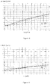
- the figure 2 represents the same spectrometer as the figure 1 , but in an XZ plane orthogonal to the YZ plane.
- the Dyson spectrometer shown Figures 1 and 2 comprises a convex plane lens 2 and a concave concentric diffraction grating 4.
- This Dyson spectrometer comprises an input slot 1 or an optical fiber bundle in an object plane and an output port 10 in an image plane 7.
- the concave network 4 has a meridian plane (YZ) passing through its vertex 6 and orthogonal to the principal direction of its lines.
- the lens 2 and the grating 4 have a common optical axis 5 passing through their respective vertices and normal to their respective surfaces.
- the two spherical surfaces 3 and 4 thus have their centers of curvature close to and on the axis Z 5, hence the name of a concentric spectrometer.
- the object plane and the image plane of the spectrometer are located on the plane face 8 of the plano-convex lens 2 which is hemispherical.
- a source point 9 located on the entrance slit 1 emits a polychromatic light beam which penetrates into the lens through its plane face 8 close to or coincident with the entrance slit 1, the incident beam is then refracted by the spherical surface. 3 of the lens 2 to then reach the diffraction grating 4 which diffracts by reflection a diffracted beam shown schematically by a set of monochromatic light beams directed towards the lens 2.
- the diffracted light beam is focused by the lens 2 in the image plane of 7 at a position 10 relative to the meridian plane (YZ), the light spectrum of the diffracted beam is dispersed along the y axis.
- FIG. 3 The imaging performance of such a system optimized for the parameters indicated above are illustrated figure 3 .
- the diameter of the RMS radius is between 3 and 18 ⁇ m over the entire image field.
- Distortion in any imaging system is also an important parameter.
- the notion of distortion is always important but it is complicated by the fact that the spectral dimension is introduced.
- All the assemblies used to illustrate the invention have an overall distortion (Smile and Keystone) of less than or equal to 7 .mu.m, which is very low.
- the present invention proposes the use of a so-called "corrected" diffraction grating 4 in place of the diffraction grating with parallel and equidistant lines on a spherical support used in the previous Dyson fixtures.
- the uncorrected concave lattice has long been known, the engraved lines of which are constituted parallel and equidistant when they are projected on the plane passing through the vertex 6 of the grating and orthogonal to the axis 5.
- corrected network is understood to mean a diffraction grating whose features are not equidistant and parallel, but whose feature lines are optimized in such a way that the image quality of the spectrometer is generally improved, considering in particular only network aberrations, but also those of the optical system between the input-output ports.
- a first embodiment of the invention is based on the use of a concave diffraction grating 4 whose lines (or grooves) are neither exactly parallel nor exactly equidistant.
- the line density and the direction of the lines are slightly modified according to the point of the surface of the network 4 considered so as to improve the overall image quality of the spectrometer.
- the local density of the lattice lines and the direction of the lines are optimized numerically so as to minimize the RMS radius of the image spot while maintaining low distortions on the image field.
- the manufacture of a network thus optimized is possible in particular by holography, as well as its replication.
- the figure 4 shows the image quality performance of a Dyson imaging spectrometer using such a grating according to a first embodiment of the invention, in which the plano-convex lens is a hemispherical lens, whose plane face is located on the object plane and on the image plane of the spectrometer.
- the comparison of the figure 3 and 4 shows the improvement in terms of image quality provided by the use of a concave corrected network in a Dyson-type spectrometer. Indeed, the size of the image spot ( Fig. 4 ) is thus on average reduced by 30% compared to the spectrometer whose network is a network with parallel lines and equidistant on a spherical surface ( Fig 3 ).
- This figure schematically shows a Dyson spectrometer whose optical collimation and focusing system is modified.
- the input 1 of the spectrometer is in or very close to the lens 2 lens, but what differs is that the output 11 is located at a significant distance from the exit face of the lens, in our example and our calculations the distance between the detector and the glass is 30 mm.
- the refractive optical system shown figure 7 comprises a rather thin lens (convex plane) 12 to which is joined a glass plate 13 which extends only on the input side of the imaging spectrometer.
- the glass of the blade 13 may be identical to that of the lens 12 or different, for example to reduce chromatic aberrations.
- the free space thus created at the output is particularly interesting when the detectors used and their technology make it impossible to place them in the immediate vicinity of the glass mainly for congestion problems.
- This is particularly the case for cooled detectors which are generally sealed in a closed enclosure by a transparent window and placed at a distance from the sensitive surface thus preventing the establishment of the sensitive surface in the immediate vicinity of the lens 2.
- the optical system shown figure 7 thus allows an easy use of this kind of detector.
- the curves of the figure 8 illustrate the performances in terms of image quality of an imaging spectrometer having a network with parallel and equidistant lines on a spherical support, the spectrometer comprising the optical system represented on the figure 7 , with entry into the glass (or very close) and exit into the air at a distance of 30 mm from the exit face of the lens.
- These illustrated performances figure 8 are very degraded compared to the previous case where entry and exit are in the glass ( Figure 3 and Figure 4 ).
- the RMS radius of the figure 8 is of the order of 30 microns over the entire spectrum and for the three image points of the entrance slit.
- This network leads to an imaging spectrometer whose output is in the air at 30 mm from the glass ( figure 6 ) and having the imagery performance shown on the figure 9 .
- the radius RMS is decreased especially for wavelengths between 1 and 2 microns.
- a third embodiment of the invention is an improvement of the second embodiment.
- the spectrometer comprises an optical system as described in connection with the figure 6 , with inlet 1 in the glass and outlet 11 in the air at 30 mm from the glass.
- the diffraction grating is etched on an aspherical substrate and corrected for aberrations in order to optimize the overall image quality of the spectrometer.
- the RMS radius is less than 15 microns for all wavelengths (from 1 to 2.5 ⁇ m) and over the entire field of the image (source point from 0 to 10 mm).
- the imaging quality (illustrated figure 10 ) Of a system according to the 3rd embodiment, which uses a diffraction grating both corrected aberrations and engraved on an aspheric substrate is even better than the 2 nd embodiment illustrated in figure 9 .
- a spectrometer according to the 3 rd embodiment compares almost in terms of image quality with a spectrometer having the input and the output in (or very near) the glass.
- the invention therefore allows a flexible use of the Dyson assembly by allowing the addition of a substantial air space output (1 st embodiment, whose performance is illustrated figure 4 ).
- the imaging spectrometer is used as shown schematically on the figure 11 .
- Input 1 and output 7 of the imaging spectrometer are here in the air at a significant distance (about 30 mm) from the flat face of the lens 2.
- the lens 2 is a plano-convex lens much thinner than a hemispherical lens therefore less expensive and less heavy.
- the figure 12 presents a representative graph of the quality in imaging of a spectrometer using a spherical concave diffraction grating with parallel and equidistant lines and a convex plane lens whose input and output are at a distance of 30 mm.
- the RMS radius is between 45 and 80 microns over the entire spectral range in the image field. The image quality of such a device is very strongly degraded compared to all the other results presented above.
- the graph of the figure 13 represents the quality in imaging of a spectrometer according to this 4 th embodiment.
- the RMS radius is decreased by a factor of 2 (compared to the figure 12 ) especially for wavelengths between 1 and 2 microns.
- the aspherization of the network substrate thus significantly improves performance (comparison figure 12 and figure 13 ).
- the graph of the figure 14 represents picture quality of a spectrometer according to the 5th embodiment.
- the aspherical substrate and correcting aberrations enable dramatically improved imaging spectrometer performance according to this 5th embodiment. Illustrated performances figure 14 become close to those of the best spectrometers presented previously figure 3 despite the distance of 30 mm between the input-output plane and the flat face of the lens 12.
- the 4 th and 5 th embodiment of the invention provide an imaging spectrometer whose imaging performance is improved.
- the 4 th and 5 th embodiments offer an interesting alternative to the standard Dyson spectrometer where input and output plane slot must be very close to the flat face 8 of the lens 2.
- the invention provides an imaging enhancement of a Dyson-type spectrometer for spectral or hyperspectral imaging applications through the use of an aberration-corrected diffraction grating and / or whose substrate shape is aspherical.
- An aberration-corrected diffraction grating is a network whose features are no longer exactly parallel and equidistant over the entire surface of the component, but whose feature lines are optimized to improve the image quality (approaching a system where the image a point is a point) of the spectrometer throughout the image field while minimizing the distortion in the spatial and spectral dimensions of the image field.
- the various embodiments of the invention allow the improvement of an imaging spectrometer by the combined use of refractive and diffractive elements optimized to allow an imaging function of good optical quality and low distortion in the spectral and spectral dimensions. Space.
- the present invention provides not only an improvement of the imaging quality of a Dyson spectrometer but also a possibility of new use of this type of spectrometer with inlet slit and / or detector in the air at a significant distance from The lens. This distance makes it possible to have more space in and out to place the source and the imaging detector. This configuration also makes it possible to use a refractive component much more compact than a hemispherical lens used in earlier Dyson spectrometers.
- the use of a non-parallel and non-equidistant line network in a Dyson-type spectrometer is particularly interesting for spectral or hyperspectral imaging.
- the network is manufactured on an aspherical support which allows a further improvement of the imaging qualities of the spectrometer.
Description
La présente invention concerne un spectromètre imageur de type Dyson de qualité image améliorée pour des applications dans le domaine de la spectrométrie et de l'imagerie hyperspectrale.The present invention relates to a Dyson imaging spectrometer of improved image quality for applications in the field of spectrometry and hyperspectral imaging.
Dans ce document, on entend par spectromètre imageur un spectromètre apte à former une image d'une fente d'entrée résolue spatialement suivant la hauteur de cette fente et résolue spectralement pour chaque point image de cette fente. Les spectromètres imageurs comprennent en particulier les spectromètres pour l'imagerie hyperspectrale et les spectromètre à fibres optiques.In this document, an imaging spectrometer is understood to mean a spectrometer able to form an image of an input slit resolved spatially according to the height of this slit and resolved spectrally for each image point of this slit. Imaging spectrometers include in particular spectrometers for hyperspectral imaging and optical fiber spectrometers.
Plus particulièrement, l'invention concerne un spectromètre imageur amélioré pour former une image présentant une grande qualité image sur tout le champ image tout en ayant des distorsions spatiale et spectrale très faibles, afin d'obtenir une image de grande résolution spectrale et spatiale dans tout le champ image.More particularly, the invention relates to an improved imaging spectrometer for forming an image having a high image quality throughout the image field while having very small spatial and spectral distortions, in order to obtain an image of high spectral and spatial resolution in all the image field.
Il existe de nombreux montages optiques de spectromètres. Un spectromètre imageur comprend habituellement une fente d'entrée, un élément dispersif, qui est en général un réseau de diffraction ou un prisme, différents éléments optiques (lentilles ou miroirs) permettant de former l'image de la fente d'entrée sur un dispositif de détection (fente de sortie mobile et détecteur ou bien matrice de détecteurs linéaires ou 2D).There are many optical assemblies of spectrometers. An imaging spectrometer usually comprises an entrance slit, a dispersive element, which is generally a diffraction grating or a prism, different optical elements (lenses or mirrors) for forming the image of the entrance slit on a device detection (mobile output slot and detector or matrix of linear or 2D detectors).
Certains domaines d'application de la spectrométrie nécessitent des appareils spectrométriques ayant des propriétés spécifiques d'imagerie. Un spectromètre imageur doit présenter une très bonne qualité d'imagerie, non seulement dans la dimension spectrale (qui est la qualité classique de résolution spectrale d'un spectromètre) mais aussi dans la dimension spatiale c'est-à-dire une bonne résolution spatiale suivant la direction de la fente d'entrée.Some areas of application of spectrometry require spectrometric devices with specific imaging properties. An imaging spectrometer must have a very good quality of imaging, not only in the spectral dimension (which is the classic quality of spectral resolution of a spectrometer) but also in the spatial dimension that is to say a good spatial resolution following the direction of the entrance slot.
Un spectromètre imageur doit aussi présenter les propriétés suivantes :
- un grand champ, c'est à dire que la qualité image est conservée pour des hauteurs de fente importante,
- une grande ouverture numérique, afin de capter le maximum de lumière,
- une faible distorsion, pour un spectromètre imageur la distorsion peut être spectrale et/ou spatiale.
- a large field, that is to say that the image quality is preserved for large slot heights,
- a large numerical aperture, in order to capture the maximum of light,
- a low distortion, for an imaging spectrometer the distortion can be spectral and / or spatial.
Un premier domaine nécessitant de tels spectromètres est l'imagerie hyperspectrale qui consiste à s'intéresser non plus seulement au spectre obtenu par la lumière entrant par l'intégralité de la fente d'entrée mais à étudier le spectre de chaque point spatialement distinct le long de la fente d'entrée. L'imagerie hyperspectrale s'est récemment développée grâce à de nouveaux détecteurs matriciels performants, offrant à la fois une très grande résolution grâce à des détecteurs élémentaires (pixels) ayant une taille de l'ordre de quelques microns et une très grande sensibilité. Un dispositif optique (généralement un télescope) forme l'image de la scène à analyser sur la fente d'entrée du spectromètre, chaque détail spatial de la scène le long de la fente d'entrée est ensuite analysé spectralement. La qualité de l'image produite par le spectromètre est donc primordiale aussi bien dans la direction de la dispersion spectrale qui détermine la capacité du système à discriminer deux longueurs d'onde proches que dans la direction spatiale qui permet de discriminer deux points objets très proches (ce qui correspond donc au détail de l'image dans la direction de la fente).A first area requiring such spectrometers is hyperspectral imaging, which consists of focusing not only on the spectrum obtained by the light entering through the entire entrance slit but on studying the spectrum of each spatially distinct point along the spectrum. of the entrance slot. Hyperspectral imaging has recently developed thanks to new high performance matrix detectors, offering both a very high resolution thanks to elementary detectors (pixels) having a size of the order of a few microns and a very high sensitivity. An optical device (usually a telescope) forms the image of the scene to be analyzed on the input slot of the spectrometer, each spatial detail of the scene along the entrance slot is then spectrally analyzed. The quality of the image produced by the The spectrometer is therefore crucial both in the direction of the spectral dispersion which determines the ability of the system to discriminate between two near wavelengths and in the spatial direction which makes it possible to discriminate between two very close object points (which corresponds to the detail of the image in the direction of the slot).
Dans un exemple d'application, un spectromètre pour imagerie hyperspectrale est monté sur un avion ou un satellite qui se déplace au dessus de la terre dans une direction perpendiculaire à la fente d'entrée. Le balayage de la scène est réalisé par le déplacement du spectromètre entier par rapport à la scène, ou bien par un système d'imagerie en avant du spectromètre, la fente d'entrée restant fixe. A chaque position du spectromètre (ou du système de balayage) correspond une colonne image de la fente d'entrée. A partir d'un ensemble de colonnes images, le système peut reconstituer une image de l'ensemble de la scène à des centaines de longueurs d'onde différentes (suivant la discrétisation du spectre choisi pour l'analyse).In one exemplary application, a hyperspectral imaging spectrometer is mounted on an aircraft or satellite that moves above the earth in a direction perpendicular to the entrance slit. The scanning of the scene is accomplished by moving the entire spectrometer relative to the scene, or by an imaging system in front of the spectrometer, the entrance slit remaining fixed. At each position of the spectrometer (or scanning system) corresponds an image column of the input slot. From a set of image columns, the system can reconstruct an image of the entire scene at hundreds of different wavelengths (depending on the discretization of the spectrum chosen for the analysis).
Un second domaine d'applications concerne les spectromètres à fibres optiques, dans lesquels la fente d'entrée est remplacée par un grand nombre de fibres optiques alignées formant ainsi une fente d'entrée constituée de la juxtaposition d'une multitude de petites sources quasi-ponctuelles. Un spectromètre à fibres permet l'analyse spectrale d'un très grand nombre d'échantillons (un échantillon par fibre) et en simultané (analyse en parallèle) sur un seul détecteur matriciel. Une ligne de pixels ou un groupe de lignes de pixels analyse le spectre correspondant à l'image d'une fibre optique d'entrée sur le détecteur matriciel. Il est alors essentiel de fournir une analyse spectrale indépendante pour chaque fibre. Un spectromètre à fibre doit aussi présenter une très bonne qualité image et une faible distorsion à la fois dans la dimension spectrale et dans la dimension spatiale.A second field of application concerns fiber optic spectrometers, in which the entrance slot is replaced by a large number of aligned optical fibers thus forming an entrance slot consisting of the juxtaposition of a multitude of small quasi-optical sources. point. A fiber spectrometer allows the spectral analysis of a very large number of samples (one sample per fiber) and simultaneously (parallel analysis) on a single matrix detector. A row of pixels or a group of rows of pixels analyzes the spectrum corresponding to the image of an input optical fiber on the matrix detector. It is therefore essential to provide independent spectral analysis for each fiber. A fiber spectrometer must also have very good image quality and low distortion both in the spectral dimension and in the spatial dimension.
On connaît un type de spectromètre imageur ayant certaines des propriétés recherchées, il s'agit des spectromètres concentriques réflectifs ou réfractifs décrits dans la littérature par Mertz (1977) et Thévenon (Brevet
Un spectromètre imageur comprenant un élément optique réfractif est basé sur un montage inventé par
Le brevet
D'autres types de spectromètres utilisent uniquement un réseau de diffraction sans autre système optique réflectif ni réfractif de collimation et/ou de focalisation. Dans ces spectromètres, le réseau de diffraction remplit plusieurs fonctions : la fonction de dispersion spectrale et la fonction de collecte du flux d'entrée et/ou de focalisation du flux de sortie. Ces spectromètres peuvent être utilisés en imagerie, mais la qualité image dans le champ est beaucoup moins bonne et la distorsion est importante. Dans un tel spectromètre, un réseau de diffraction dont les traits ne sont pas parallèles et équidistants ou dont le support est asphérique peut permettre de corriger certaines aberrations. La Société Jobin Yvon a développé des réseaux holographiques particuliers optimisés pour des spectromètres non imageurs et sans optique réfractive. Ainsi, le document
Le document
Les réseaux décrits dans les documents
Le brevet
Le document "
Il n'est pas habituel d'utiliser un réseau dit « corrigé » dans un spectromètre concentrique ayant un système optique réfractif. On s'attend généralement à une meilleure qualité image dans un spectromètre comprenant un système optique à base de miroirs, du fait de l'absence d'aberrations chromatiques. L'optimisation d'un réseau de diffraction correspond à des degrés de liberté supplémentaires et est plus complexe à définir dans un spectromètre de type Dyson. De manière surprenante, cette optimisation du réseau permet à l'invention non seulement d'améliorer la qualité image mais aussi de définir des configurations de spectromètres plus pratiques, avec plus d'espace pour positionner la source et/ou le détecteur.It is not usual to use a so-called "corrected" network in a concentric spectrometer having a refractive optical system. A better image quality is generally expected in a spectrometer comprising an optical system based on mirrors, because of the absence of chromatic aberrations. The optimization of a diffraction grating corresponds to additional degrees of freedom and is more complex to define in a Dyson spectrometer. Surprisingly, this optimization of the network enables the invention not only to improve the image quality but also to define more practical spectrometer configurations, with more space to position the source and / or the detector.
Un des buts de l'invention est de proposer un spectromètre imageur compact, ayant une très bonne qualité image et une faible distorsion.One of the aims of the invention is to propose a compact imaging spectrometer having a very good image quality and a low distortion.
Un autre but de l'invention est de fournir un spectromètre imageur de bonne qualité image et offrant une plus grande flexibilité pour le positionnement de la fente d'entrée et/ou du détecteur, notamment pour être compatible avec l'utilisation de détecteurs imageurs refroidis, qui ont une distance frontale non nulle.Another object of the invention is to provide an imaging spectrometer of good image quality and offering greater flexibility for the positioning of the input slot and / or the detector, in particular to be compatible with the use of cooled imaging sensors. , which have a non-zero frontal distance.
Un autre but de l'invention est de proposer un spectromètre imageur de très grande résolution spectrale et spatiale sur un grand champ image.Another object of the invention is to provide an imaging spectrometer of very high spectral and spatial resolution over a large image field.
La qualité image d'un spectromètre est évaluée par la mesure de la tache image d'un point objet à travers le spectromètre. Cette qualité image est évaluée par la mesure de différentes taches images correspondant à différents points objet. Généralement dans un spectromètre imageur, la qualité image est évaluée au centre du champ et à des points éloignés de l'axe, ainsi qu'aux longueurs d'onde centrale et extrêmes du spectre. Une méthode connue pour évaluer la taille d'une tache image est la méthode RMS, qui consiste à tracer numériquement un ensemble de rayons, et à mesurer numériquement la distance moyenne des rayons dans le plan image par rapport au point image à travers un système parfait. Il existe des logiciels capables de simuler la réponse numérique d'un système optique quelconque et d'optimiser certains des paramètres décrivant les composants optiques le constituant.The image quality of a spectrometer is evaluated by measuring the image spot of an object point through the spectrometer. This image quality is evaluated by measuring different image spots corresponding to different object points. Typically in an imaging spectrometer, image quality is evaluated at the center of the field and at points distant from the axis, as well as at the central and extreme wavelengths of the spectrum. A known method for estimating the size of an image spot is the RMS method, which consists of digitally plotting a set of rays, and numerically measuring the average distance of the rays in the image plane from the image point through a perfect system. . There is software capable of simulating the numerical response of any optical system and optimizing some of the parameters describing the optical components constituting it.
Le spectromètre selon l'invention est décrit par la revendication 1. La présente invention a pour but de remédier aux inconvénients des systèmes antérieurs et concerne plus particulièrement un spectromètre imageur de type Dyson comprenant un port d'entrée s'étendant selon une direction X dans un plan objet du spectromètre, ledit port d'entrée étant apte à émettre un faisceau lumineux incident, un réseau de diffraction comprenant un ensemble de traits sur un support concave, un système optique comprenant une lentille, ladite lentille comprenant une première face plane et une seconde face convexe, la face convexe de la lentille et la face concave du réseau de diffraction étant concentriques, ledit système optique étant apte à recevoir et à diriger le faisceau lumineux incident vers le réseau de diffraction, à recevoir un faisceau diffracté par le réseau de diffraction et à former une image spectrale dudit faisceau diffracté, ladite image spectrale s'étendant sur un champ image dans un plan image du spectromètre et un port de sortie dans le plan image du spectromètre, apte à recevoir une image du port d'entrée résolue spatialement selon une direction X' et résolue spectralement selon une direction Y'.The aim of the present invention is to overcome the drawbacks of the prior systems and more particularly relates to a Dyson-type imaging spectrometer comprising an input port extending in a direction X in FIG. an object plane of the spectrometer, said input port being able to emit an incident light beam, a network diffraction grating comprising a set of lines on a concave support, an optical system comprising a lens, said lens comprising a first planar face and a second convex face, the convex face of the lens and the concave face of the diffraction grating being concentric, said optical system being adapted to receive and direct the incident light beam towards the diffraction grating, to receive a beam diffracted by the diffraction grating and to form a spectral image of said diffracted beam, said spectral image extending over an image field in an image plane of the spectrometer and an output port in the image plane of the spectrometer, adapted to receive an image of the input port spatially resolved in a direction X 'and resolved spectrally in a direction Y'.
Selon l'invention, le réseau de diffraction comprend un ensemble de traits non parallèles et non équidistants et/ou le support du réseau de diffraction est asphérique de manière à améliorer la qualité image de l'image spectrale sur le champ image tout en minimisant les distorsions spectrales et de champ.According to the invention, the diffraction grating comprises a set of non-parallel and non-equidistant strokes and / or the support of the diffraction grating is aspherical so as to improve the image quality of the spectral image on the image field while minimizing the spectral and field distortions.
Selon l'invention, le réseau de diffraction comprend un ensemble de traits non parallèles et/ou non équidistants apte à former une image spectrale dans un champ plan dont la qualité image est améliorée, tout en maintenant faibles les distorsions spectrales et de champ.According to the invention, the diffraction grating comprises a set of non-parallel and / or non-equidistant lines capable of forming a spectral image in a planar field whose image quality is improved, while keeping the spectral and field distortions low.
Selon l'invention, la surface concave du réseau de diffraction est une surface ellipsoïdale de révolution.According to the invention, the concave surface of the diffraction grating is an ellipsoidal surface of revolution.
Selon l'invention, le système optique réfractif comprend une lentille hémisphérique et une lame à faces planes et parallèles, ladite lame étant accolée à la face plane de la lentille et disposée sur le trajet optique du faisceau incident entre le port d'entrée et le réseau de diffraction, le plan objet du spectromètre étant situé sur une face de la lame et le plan image du spectromètre étant séparé de la lentille par un espace vide.According to the invention, the refractive optical system comprises a hemispherical lens and a plate with flat and parallel faces, said blade being contiguous to the plane face of the lens and disposed on the optical path of the incident beam between the input port and the diffraction grating, the object plane of the spectrometer being located on one face of the plate and the image plane of the spectrometer being separated from the lens by a void space.
Les matériaux de la lentille et de la lame sont aptes à compenser la dispersion chromatique sur le champ de l'image.The materials of the lens and the blade are able to compensate for the chromatic dispersion on the field of the image.
Selon un autre mode de réalisation, la lentille est une lentille mince plan-convexe et les plans objet et image du spectromètre sont séparés de la face plane de la lentille par un espace vide. Avantageusement, l'espace vide a une épaisseur optique typiquement inférieure ou égale à 15% du rayon de courbure du réseau.According to another embodiment, the lens is a plano-convex thin lens and the object and image planes of the spectrometer are separated from the flat face of the lens by a void space. Advantageously, the empty space has an optical thickness typically less than or equal to 15% of the radius of curvature of the network.
Avantageusement, le spectromètre comprend un détecteur matriciel disposé dans le plan image pour former une image spectrale du port d'entrée. Avantageusement, le spectromètre comprend une enceinte comprenant un détecteur et une fenêtre, la surface sensible du détecteur étant placée derrière ladite fenêtre, ladite enceinte étant apte à refroidir ledit détecteur. L'espace vide entre la lentille et le plan image permet notamment d'utiliser un détecteur refroidi souvent plus encombrant qu'un détecteur non refroidi.Advantageously, the spectrometer comprises a matrix detector disposed in the image plane to form a spectral image of the input port. Advantageously, the spectrometer comprises an enclosure comprising a detector and a window, the sensitive surface of the detector being placed behind said window, said enclosure being able to cool said detector. The empty space between the lens and the image plane makes it possible in particular to use a cooled detector which is often more bulky than a non-cooled detector.
Selon un mode de réalisation particulier, le spectromètre imageur comprend un ensemble de fibres optiques dont les extrémités sont alignées suivant un axe sur le port d'entrée et le détecteur est apte à former un spectre image correspondant respectivement à chaque fibre optique.According to a particular embodiment, the imaging spectrometer comprises a set of optical fibers whose ends are aligned along an axis on the input port and the detector is able to form an image spectrum respectively corresponding to each optical fiber.
La présente invention concerne également les caractéristiques qui ressortiront au cours de la description qui va suivre et qui devront être considérées isolément ou selon toutes leurs combinaisons techniquement possibles.The present invention also relates to the features which will emerge in the course of the description which follows and which will have to be considered individually or in all their technically possible combinations.
Cette description est donnée à titre d'exemple non limitatif et fera mieux comprendre comment l'invention peut être réalisée en référence aux dessins annexés sur lesquels :
- la
figure 1 est une vue en coupe dans le plan y-z (plan méridien) d'un spectromètre Dyson classique fonctionnant dans l'ordre -1, l'entrée et le spectre étalé en sortie étant placés sur (ou très proche de) la surface plane de la lentille ; - la
figure 2 est une vue en coupe dans le plan x-z d'un spectromètre Dyson classique fonctionnant dans l'ordre -1, les rayons sont tracés pour un point objet placés à 10 mm dans la direction x perpendiculaire au plan de diffraction. Les points objet et image sont de part et d'autre du plan méridien (plan y-z) ; - la
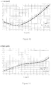
figure 3 illustre les performances en termes de qualité d'image d'un spectromètre Dyson classique de l'art antérieur. Ce graphique représente le rayon RMS (Root Min Square) de la tache image d'un point source dans le plan image, ou plan du détecteur. Le rayon RMS est donné pour trois positions du point source dans le champ objet (c'est-à-dire à trois positions en hauteur le long de la fente d'entrée) en fonction de la longueur d'onde; - la
figure 4 illustre les performances en termes de qualité d'image d'un spectromètre selon un mode de réalisation de l'invention utilisant un réseau de diffraction corrigé des aberrations dont les traits ne sont plus strictement parallèles et équidistants. Ce graphique représente le rayon RMS de la tache image pour trois positions du point source dans le champ objet en fonction de la longueur d'onde. - la
Figure 5 représente schématiquement les deux défauts de distorsion d'un spectromètre imageur dans le plan image : le Smile (S) et le Keystone (K). - La
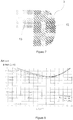
Figure 6 présente une vue en coupe d'un mode de réalisation d'un spectromètre de type Dyson modifié selon l'invention, dans lequel le port d'entrée du spectromètre est sur ou très proche d'une face plane du système optique, et dans lequel le plan de focalisation image (plan du détecteur) est à une distance notable du système optique. - La
Figure 7 représente une vue en coupe un exemple de réalisation d'un système optique composé d'une lentille hémisphérique et d'une lame de verre, apte à être utilisé dans le spectromètre de lafigure 6 . - La
Figure 8 illustre les performances en termes de qualité d'image d'un montage Dyson classique qui serait utilisé avec le port d'entrée dans le verre du système optique et le port de sortie à une distance de 30 mm du verre. - La
Figure 9 illustre les performances en termes de qualité d'image d'un montage selon un mode de réalisation de l'invention comprenant un réseau de diffraction gravé sur support asphérique (de type ellipsoïdal) et dans lequel les ports d'entrée et de sortie sont dans l'air à une distance de 30 mm du système optique. - La
Figure 10 illustre les performances en termes de qualité d'image d'un montage selon un autre mode de réalisation de l'invention comprenant un réseau de diffraction corrigé des aberrations et gravé sur support asphérique (type ellipsoïdal) et dans lequel les ports d'entrée et de sortie sont dans l'air à 30 mm du système optique. - La
Figure 11 présente une vue en coupe d'un autre mode de réalisation d'un spectromètre de type Dyson modifié selon l'invention, comprenant une lentille plan-convexe simple et dans lequel le port d'entrée du spectromètre (comprenant une fente d'entrée ou un bundle de fibre optique) et le plan de focalisation image (plan du détecteur) sont à une distance notable de la lentille. - La
Figure 12 illustre les performances en termes de qualité d'image d'un montage Dyson classique comprenant un réseau de diffraction concave sphérique non corrigé des aberrations et utilisé avec l'entrée et la sortie dans l'air à 30 mm du verre de la lentille. - La
Figure 13 illustre les performances en termes de qualité d'image d'un montage selon un mode de réalisation de l'invention comprenant un réseau de diffraction concave non corrigé des aberrations gravé sur substrat asphérique (type ellipsoïdal) et dans lequel les ports d'entrée et de sortie sont dans l'air à une distance de 30 mm du système optique. - La
Figure 14 illustre les performances en termes de qualité d'image d'un montage selon un mode de réalisation de l'invention comprenant un réseau de diffraction concave corrigé des aberrations et gravé sur substrat asphérique (type ellipsoïdal) et dans lequel les ports d'entrée et de sortie sont dans l'air à une distance de 30 mm du système optique.
- the
figure 1 is a sectional view in the yz plane (meridian plane) of a conventional Dyson spectrometer operating in the order -1, the input and the spectrum spread out being placed on (or very close to) the flat surface of the lens; - the
figure 2 is a sectional view in the xz plane of a conventional Dyson spectrometer operating in order -1, the rays are plotted for an object point placed at 10 mm in the x direction perpendicular to the diffraction plane. The object and image points are on both sides of the meridian plane (yz plane); - the
figure 3 illustrates the image quality performance of a conventional Dyson spectrometer of the prior art. This graph represents the RMS (Root Min Square) radius of the image spot of a source point in the image plane, or detector plane. The RMS radius is given for three positions of the source point in the object field (i.e., three positions in height along the input slot) as a function of the wavelength; - the
figure 4 illustrates the performance in terms of image quality of a spectrometer according to an embodiment of the invention using an aberration-corrected diffraction grating whose features are no longer strictly parallel and equidistant. This graph represents the RMS radius of the image spot for three positions of the source point in the object field as a function of wavelength. - the
Figure 5 schematically represents the two distortion defects of an imaging spectrometer in the image plane: Smile (S) and Keystone (K). - The
Figure 6 shows a sectional view of an embodiment of a modified Dyson-type spectrometer according to the invention, in which the input port of the spectrometer is on or very close to a plane face of the optical system, and in which the image focusing plane (detector plane) is at a significant distance from the optical system. - The
Figure 7 is a sectional view of an exemplary embodiment of an optical system composed of a hemispherical lens and a glass slide, suitable for use in the spectrometer of thefigure 6 . - The
Figure 8 illustrates the image quality performance of a conventional Dyson mount that would be used with the input port in the glass of the optical system and the output port at a distance of 30 mm from the lens. - The
Figure 9 illustrates the performance in terms of image quality of an assembly according to an embodiment of the invention comprising an aspherical-type diffraction grating (of ellipsoidal type) and in which the input and output ports are in air at a distance of 30 mm from the optical system. - The
Figure 10 illustrates the performance in terms of image quality of an assembly according to another embodiment of the invention comprising an aberration-corrected diffraction grating etched on aspherical support (ellipsoidal type) and in which the input and output ports output are in the air at 30 mm from the optical system. - The
Figure 11 shows a sectional view of another embodiment of a modified Dyson-type spectrometer according to the invention, comprising a simple plano-convex lens and in which the input port of the spectrometer (comprising an entrance slit or an optical fiber bundle) and the image focusing plane (detector plane) are at a significant distance from the lens. - The
Figure 12 illustrates the image quality performance of a conventional Dyson assembly comprising a non-corrected aberration spherical concave diffraction grating and used with the input and output in the air at 30 mm from the lens glass. - The
Figure 13 illustrates the performance in terms of image quality of an arrangement according to an embodiment of the invention comprising an uncorrected concave diffraction grating of aberrations etched on aspherical substrate (ellipsoidal type) and in which the input ports and output are in the air at a distance of 30 mm from the optical system. - The
Figure 14 illustrates the performance in terms of image quality of an assembly according to an embodiment of the invention comprising an aberration-corrected concave diffraction grating etched on an aspherical substrate (ellipsoidal type) and in which the input ports and output are in the air at a distance of 30 mm from the optical system.
Pour la clarté de la mise en évidence des avantages de l'invention nous allons comparer différentes configurations de spectromètres ayant les caractéristiques suivantes communes :
- Ouverture numérique du faisceau d'entrée correspondant à un nombre d'ouverture dans l'air de F/2 : ON = 0,2425 ;
- Plage spectrale : 1000 nm à 2500 nm ;
- Hauteur de la fente d'entrée : 20 mm qui correspond donc au champ objet ;
- Grandissement : 1, qui est le grandissement nominal de ce type de montage ;
- Taille du détecteur : 10 mm dans la direction du spectre et 20 mm dans la direction spatiale ;
- Le rayon de courbure du réseau : 250 mm, cela fixe ainsi grossièrement l'encombrement du système et la densité de traits du réseau, ici
environ 30 tr/mm.
- Digital opening of the input beam corresponding to an opening number in the air of F / 2: ON = 0.2425;
- Spectral range: 1000 nm to 2500 nm;
- Height of the entrance slot: 20 mm which corresponds to the object field;
- Magnification: 1, which is the nominal magnification of this type of mounting;
- Detector size: 10 mm in the direction of the spectrum and 20 mm in the spatial direction;
- The radius of curvature of the network: 250 mm, this thus roughly fixes the size of the system and the line density of the network, here about 30 tr / mm.
La qualité image et la minimisation de la distorsion sont les critères d'évaluation de la qualité d'imagerie du système.Image quality and minimizing distortion are the criteria for evaluating the imaging quality of the system.
Le montage fonctionne dans l'ordre de diffraction -1 du réseau (ordre diffraction vers l'axe de symétrie du système).The assembly operates in the order of diffraction -1 of the grating (order diffraction towards the axis of symmetry of the system).
Ces conditions fixes permettent de comparer objectivement les performances des différentes versions de spectromètres Dyson en imagerie.These fixed conditions make it possible to objectively compare the performances of the different versions of Dyson spectrometers in imaging.
Il est entendu que la présente invention n'est pas limitée à la configuration optique présentée dans l'exemple mais peut être étendue à tout montage de type Dyson utilisé dans tout ordre de diffraction.It is understood that the present invention is not limited to the optical configuration shown in the example but can be extended to any Dyson type of fixture used in any diffraction order.
La
Le spectromètre Dyson représenté
Le réseau concave 4 possède un plan méridien (YZ) passant par son sommet 6 et orthogonal à la direction principale de ses traits. La lentille 2 et le réseau 4 ont un axe optique commun 5 passant par leurs sommets respectifs et normal à leurs surfaces respectives. Les deux surfaces sphérique 3 et 4 ont ainsi leurs centres de courbure proches et sur l'axe Z 5, d'où l'appellation de spectromètre concentrique.The concave network 4 has a meridian plane (YZ) passing through its
Dans le mode de réalisation représenté sur les
Un point source 9 situé sur la fente d'entrée 1 émet un faisceau de lumière polychromatique qui pénètre dans la lentille par sa face plane 8 proche ou bien confondue avec la fente d'entrée 1, le faisceau incident est ensuite réfractée par la surface sphérique 3 de la lentille 2 pour ensuite atteindre le réseau de diffraction 4 qui diffracte par réflexion un faisceau diffracté représenté schématiquement par un ensemble de faisceaux lumineux monochromatiques dirigés vers la lentille 2. Le faisceau lumineux diffracté est focalisé par la lentille 2 dans le plan image de sortie 7 à une position 10 par rapport au plan méridien (YZ), le spectre lumineux du faisceau diffracté est dispersé selon l'axe y.A
Les performances en imagerie d'un tel système optimisé pour les paramètres indiqués plus haut sont illustrées
Le diamètre du rayon RMS est compris entre 3 et 18 µm sur tout le champ image.The diameter of the RMS radius is between 3 and 18 μm over the entire image field.
La distorsion dans un système d'imagerie quelconque est aussi un paramètre important. Dans un spectromètre imageur la notion de distorsion est toujours importante mais elle se complique du fait de la dimension spectrale qui est introduite. On parle alors de deux défauts de distorsion le « Smile » ou S dans la dimension spectrale et le « Keystone» ou K dans la dimension spatiale comme le montre schématiquement la
La présente invention propose l'utilisation d'un réseau de diffraction 4 dit «corrigé » à la place du réseau de diffraction à traits parallèles et équidistants sur un support sphérique utilisé dans les montages antérieurs Dyson. On connaît depuis longtemps le réseau concave non corrigé dont les traits gravés qui le constituent sont parallèles et équidistants lorsqu'ils sont projetés sur le plan passant par le sommet 6 du réseau et orthogonal à l'axe 5.The present invention proposes the use of a so-called "corrected" diffraction grating 4 in place of the diffraction grating with parallel and equidistant lines on a spherical support used in the previous Dyson fixtures. The uncorrected concave lattice has long been known, the engraved lines of which are constituted parallel and equidistant when they are projected on the plane passing through the
Dans ce document, on entend par « réseau corrigé » un réseau de diffraction dont les traits ne sont pas équidistants et parallèles, mais dont le tracé des traits est optimisé de façon à ce que la qualité image du spectromètre soit globalement améliorée, compte tenu non seulement des aberrations du réseau, mais aussi de celles du système optique entre les ports d'entrée sortie.In this document, the term "corrected network" is understood to mean a diffraction grating whose features are not equidistant and parallel, but whose feature lines are optimized in such a way that the image quality of the spectrometer is generally improved, considering in particular only network aberrations, but also those of the optical system between the input-output ports.
Un premier mode de réalisation de l'invention repose sur l'utilisation d'un réseau de diffraction 4 concave dont les traits (ou sillons) ne sont ni exactement parallèles ni exactement équidistants. La densité de traits et la direction des traits sont légèrement modifiées selon le point de la surface du réseau 4 considéré de façon à améliorer la qualité image globale du spectromètre.A first embodiment of the invention is based on the use of a concave diffraction grating 4 whose lines (or grooves) are neither exactly parallel nor exactly equidistant. The line density and the direction of the lines are slightly modified according to the point of the surface of the network 4 considered so as to improve the overall image quality of the spectrometer.
La densité locale des traits du réseau et la direction des traits sont optimisées numériquement de manière à minimiser le rayon RMS de la tache image tout en conservant des distorsions faibles sur le champ image. La fabrication d'un réseau ainsi optimisé est possible notamment par holographie, ainsi que sa réplication.The local density of the lattice lines and the direction of the lines are optimized numerically so as to minimize the RMS radius of the image spot while maintaining low distortions on the image field. The manufacture of a network thus optimized is possible in particular by holography, as well as its replication.
La
La comparaison de la
Un second mode de réalisation particulier de l'invention va être présenté en lien avec la
Cette figure représente schématiquement un spectromètre Dyson dont le système optique de collimation et de focalisation est modifié. L'entrée 1 du spectromètre est dans ou très proche du verre de la lentille 2, mais ce qui diffère est que la sortie 11 est situé à une distance notable de la face de sortie de la lentille, dans notre exemple et nos calculs la distance entre le détecteur et le verre est de 30 mm. Le système optique réfractif illustré
L'espace libre ainsi créé en sortie est particulièrement intéressant lorsque les détecteurs utilisés et leur technologie rendent impossible de les placer à proximité immédiate du verre principalement pour des problèmes d'encombrement. C'est en particulier le cas pour les détecteurs refroidis qui sont en général scellés dans une enceinte fermée par un hublot transparent et placé à une certaine distance de la surface sensible empêchant ainsi la mise en place de la surface sensible au voisinage immédiat de la lentille 2. Le système optique représenté
Les courbes de la
Le second mode de réalisation de l'invention utilise un réseau de diffraction gravé sur un substrat asphérique. La surface asphérique nécessaire et réalisable par les moyens actuels de production est de type ellipsoïdal. Le substrat reste à symétrie de révolution autour de l'axe Z 5. Le profil asphérique de révolution est donné par la formule suivante : 
- où h est l'élévation ;
- R est le rayon de courbure ;
- r la position radial du point considéré par
rapport au centre 6 ; - k est la constante de conicité ;
- pour une ellipse on a -1<k<0, pour k =0 il s'agit d'une sphère.
- where h is the elevation;
- R is the radius of curvature;
- r the radial position of the point considered with respect to the
center 6; - k is the taper constant;
- for an ellipse we have -1 <k <0, for k = 0 it is a sphere.
Dans un exemple du second mode de réalisation, le substrat du réseau de diffraction est asphérique avec un rayon de courbure 250 mm et une constante de conicité k=-0,125. Ce réseau permet d'aboutir à un spectromètre imageur dont la sortie est dans l'air à 30 mm du verre (
Un troisième mode de réalisation de l'invention est un perfectionnement du seconde mode de réalisation. Le spectromètre comprend un système optique tel que décrit en lien avec la
La
La qualité d'imagerie (illustrée
Il est intéressant de noter qu'un spectromètre conforme au 3ème mode de réalisation rivalise quasiment en terme de qualité image avec un spectromètre ayant l'entrée et la sortie dans (ou très proche) du verre. L'invention permet donc une souplesse d'utilisation du montage Dyson en permettant l'ajout d'un espace d'air conséquent en sortie (1er mode de réalisation, dont les performances sont illustrées
Un quatrième et un cinquième mode de réalisation de l'invention sont présentés dans le paragraphe suivant en lien avec les
Le spectromètre imageur est utilisé comme représenté schématiquement sur la
La
Selon un 4ème mode de réalisation, le spectromètre utilise un réseau de diffraction concave classique gravé sur un substrat asphérique, et plus particulièrement sur une surface ellipsoïdale de révolution, dont la constante de conicité vaut k=-0,248. Le graphique de la
Selon un 5ème mode de réalisation, le spectromètre utilise un réseau de diffraction concave corrigé des aberrations gravé sur un substrat asphérique, et plus particulièrement sur une surface ellipsoïdale de révolution, dont la constante de conicité vaut k=-0,260. Le graphique de la
Les 4ème et 5ème mode de réalisation de l'invention proposent un spectromètre imageur dont les performances en imagerie sont améliorées.The 4 th and 5 th embodiment of the invention provide an imaging spectrometer whose imaging performance is improved.
Les 4ème et 5ème modes de réalisation offrent une alternative intéressante au spectromètre Dyson standard où fente d'entrée et plan de sortie doivent être très proches de la face plane 8 de la lentille 2.The 4 th and 5 th embodiments offer an interesting alternative to the standard Dyson spectrometer where input and output plane slot must be very close to the
L'invention permet une amélioration en imagerie d'un spectromètre de type Dyson pour des applications en imagerie spectrale ou hyperspectrale grâce à l'utilisation d'un réseau de diffraction corrigé des aberrations et/ou dont la forme du substrat est asphérique.The invention provides an imaging enhancement of a Dyson-type spectrometer for spectral or hyperspectral imaging applications through the use of an aberration-corrected diffraction grating and / or whose substrate shape is aspherical.
Un réseau de diffraction corrigé des aberrations est un réseau dont les traits ne sont plus exactement parallèles et équidistants sur toute la surface du composant mais dont le tracé des traits est optimisé pour améliorer la qualité image (se rapprocher d'un système où l'image d'un point est un point) du spectromètre dans tout le champ image tout en minimisant la distorsion dans les dimensions spatiale et spectrale du champ image.An aberration-corrected diffraction grating is a network whose features are no longer exactly parallel and equidistant over the entire surface of the component, but whose feature lines are optimized to improve the image quality (approaching a system where the image a point is a point) of the spectrometer throughout the image field while minimizing the distortion in the spatial and spectral dimensions of the image field.
Les différents modes de réalisation de l'invention permettent l'amélioration d'un spectromètre imageur par l'utilisation combinée d'éléments réfractifs et diffractifs optimisés pour permettre une fonction d'imagerie de bonne qualité optique et de faible distorsion dans les dimensions spectrale et spatiale.The various embodiments of the invention allow the improvement of an imaging spectrometer by the combined use of refractive and diffractive elements optimized to allow an imaging function of good optical quality and low distortion in the spectral and spectral dimensions. Space.
La présente invention apporte non seulement une amélioration de la qualité d'imagerie d'un spectromètre Dyson mais aussi une possibilité d'utilisation nouvelle de ce type de spectromètre avec fente d'entrée et/ou détecteur dans l'air à une distance notable de la lentille. Cette distance permet d'avoir plus d'espace en entrée et en sortie pour placer la source et le détecteur imageur. Cette configuration permet également d'utiliser un composant réfractif beaucoup plus compact qu'une lentille hémisphérique utilisée dans les spectromètres Dyson antérieurs.The present invention provides not only an improvement of the imaging quality of a Dyson spectrometer but also a possibility of new use of this type of spectrometer with inlet slit and / or detector in the air at a significant distance from The lens. This distance makes it possible to have more space in and out to place the source and the imaging detector. This configuration also makes it possible to use a refractive component much more compact than a hemispherical lens used in earlier Dyson spectrometers.
L'utilisation d'un réseau à trait non parallèles et non équidistants dans un spectromètre de type Dyson est particulièrement intéressante pour de l'imagerie spectrale ou hyperspectrale. Selon un perfectionnement de l'invention, le réseau est fabriqué sur un support asphérique qui permet une amélioration supplémentaire des qualités d'imagerie du spectromètre.The use of a non-parallel and non-equidistant line network in a Dyson-type spectrometer is particularly interesting for spectral or hyperspectral imaging. According to an improvement of the invention, the network is manufactured on an aspherical support which allows a further improvement of the imaging qualities of the spectrometer.
Claims (6)
- A Dyson imaging spectrometer comprising:• an entry port (1) extending in a direction X in an object plane of the spectrometer, said entry port being adapted to emit an incident light beam;• a diffraction grating (4) comprising a set of lines on a concave support;• a refractive optical system comprising a lens (2), said lens comprising a plane first face (8) and a convex second face (3), the convex face (3) of the lens and the concave face of the diffraction grating (4) being concentric, said optical system being adapted to receive the incident light beam and to direct it toward the diffraction grating (4), to receive a beam diffracted by the diffraction grating, and to form a spectral image of said diffracted beam, said spectral image lying in an image field in an image plane of the spectrometer; and• an exit port in the image plane (7) of the spectrometer adapted to receive an image of the entry port spatially resolved in a direction X' and spectrally resolved in a direction Y';characterized in that:said diffraction grating comprises a set of non-parallel and non-equidistant lines and/or the support of the diffraction grating is an aspherical ellipsoidal surface of revolution in order to improve the image quality of the spectral image in the image field at the same time as minimizing spectral and field distortions,• the optical system further comprises a hemispherical lens (2) and a plate (13) with plane and parallel faces, said plate (13) lying against the plane face (8) of the lens (2) and being disposed on the optical path of the incident beam between the entry port and the diffraction grating, the object plane of the spectrometer being situated on one face of the plate (13) and the image plane of the spectrometer being separated from the lens (2) by a gap,• the materials of the lens (2) and the plate (13) being chosen to compensate chromatic dispersion over the image field.
- An imaging spectrometer according to claim 1, characterized in that the diffraction grating comprises a set of non-parallel and/or non-equidistant lines adapted to form a spectral image in an image field of improved image quality in the image field at the same time as maintaining low spectral and field distortion.
- An imaging spectrometer according to any one of claims 1 to 2, characterized in that the lens (2) is a thin plano-convex lens and the object and image planes of the spectrometer are separated from the plane face (8) of the lens (2) by a gap of optical thickness typically less than or equal to 15% of the radius of curvature of the grating (4).
- An imaging spectrometer according to any one of claims 1 to 3, characterized in that it comprises a matrix sensor disposed in the image field to form a spectral image of the entry port.
- An imaging spectrometer according to any one of claims 1 to 4, characterized in that it comprises an enclosure comprising a sensor and a window, the sensitive surface of the sensor being placed behind said window and said enclosure being adapted to cool said sensor.
- An imaging spectrometer according to any one of claims 1 to 5, characterized in that the entry port comprises a set of optical fibers aligned with an axis and the sensor is adapted to form an image spectrum of each optical fiber.
Applications Claiming Priority (2)
| Application Number | Priority Date | Filing Date | Title |
|---|---|---|---|
| FR0857466A FR2938059B1 (en) | 2008-11-03 | 2008-11-03 | DYSON-TYPE IMAGER SPECTROMETER OF ENHANCED IMAGE QUALITY AND LOW DISTORTION. |
| PCT/FR2009/052114 WO2010061090A1 (en) | 2008-11-03 | 2009-11-02 | Dyson-type imaging spectrometer having improved image quality and low distortion |
Publications (2)
| Publication Number | Publication Date |
|---|---|
| EP2368098A1 EP2368098A1 (en) | 2011-09-28 |
| EP2368098B1 true EP2368098B1 (en) | 2018-09-26 |
Family
ID=40342616
Family Applications (1)
| Application Number | Title | Priority Date | Filing Date |
|---|---|---|---|
| EP09768128.2A Not-in-force EP2368098B1 (en) | 2008-11-03 | 2009-11-02 | Dyson-type imaging spectrometer having improved image quality and low distortion |
Country Status (7)
| Country | Link |
|---|---|
| US (1) | US8520204B2 (en) |
| EP (1) | EP2368098B1 (en) |
| JP (1) | JP5639066B2 (en) |
| CA (1) | CA2742493C (en) |
| DK (1) | DK2368098T3 (en) |
| FR (1) | FR2938059B1 (en) |
| WO (1) | WO2010061090A1 (en) |
Families Citing this family (16)
| Publication number | Priority date | Publication date | Assignee | Title |
|---|---|---|---|---|
| JP2013526725A (en) * | 2010-05-18 | 2013-06-24 | アイトレス リサーチ リミテッド | Compact optical transfer system for image relay devices, hyperspectral imagers and spectrometers |
| EP2857810A1 (en) * | 2013-10-02 | 2015-04-08 | Nederlandse Organisatie voor toegepast -natuurwetenschappelijk onderzoek TNO | Monolith spectrometer |
| US20170010153A1 (en) | 2014-01-30 | 2017-01-12 | Horiba Instruments Incorporated | Spectroscopic mapping system and method |
| CN103900688A (en) * | 2014-03-28 | 2014-07-02 | 中国科学院上海技术物理研究所 | Imaging spectrometer beam splitting system based on free-form surface |
| JP6316064B2 (en) * | 2014-03-31 | 2018-04-25 | 株式会社日立ハイテクサイエンス | ICP emission spectrometer |
| GB2542737A (en) | 2014-09-19 | 2017-03-29 | Halliburton Energy Services Inc | Integrated computational elements with planar waveguide |
| US9964444B2 (en) * | 2015-05-28 | 2018-05-08 | University Of Rochester | Imaging spectrometer design tool for evaluating freeform optics |
| JP6847973B2 (en) * | 2016-10-14 | 2021-03-24 | 株式会社堀場製作所 | A spectroscope and a microscope equipped with it |
| CN107064016B (en) * | 2017-04-14 | 2019-11-12 | 中国科学院长春光学精密机械与物理研究所 | A kind of grating dispersion imaging spectrometer |
| US10345144B2 (en) * | 2017-07-11 | 2019-07-09 | Bae Systems Information And Electronics Systems Integration Inc. | Compact and athermal VNIR/SWIR spectrometer |
| US10620408B2 (en) | 2017-07-11 | 2020-04-14 | Bae Systems Information And Electronic Systems Integration Inc. | Compact orthoscopic VNIR/SWIR lens |
| US11287655B2 (en) * | 2019-06-21 | 2022-03-29 | Samsung Electronics Co.. Ltd. | Holographic display apparatus and method for providing expanded viewing window |
| CN110646091B (en) * | 2019-10-08 | 2021-08-20 | 中国科学院光电研究院 | Large-view-field Dyson spectral imaging system adopting free-form surface |
| CN111678598B (en) * | 2020-06-05 | 2023-02-24 | 中国科学院空天信息创新研究院 | Dyson curved surface prism spectral imaging system |
| WO2023122314A1 (en) | 2021-12-24 | 2023-06-29 | Horiba Instruments Incorporated | Multi-track raman well plate reader |
| WO2023151736A1 (en) * | 2022-02-11 | 2023-08-17 | Micro-Epsilon Optronic Gmbh | System and method for confocal-chromatic line distance measurement |
Family Cites Families (16)
| Publication number | Priority date | Publication date | Assignee | Title |
|---|---|---|---|---|
| FR2036613A5 (en) | 1969-03-26 | 1970-12-24 | Jobin Et G Yvon | |
| FR2334947A1 (en) | 1975-12-10 | 1977-07-08 | Instruments Sa | FIELD SPECTOGRAPH FOR A WIDE SPECTRAL DOMAIN USING A CONCAVE HOLOGRAPHIC NETWORK |
| FR2572200B1 (en) * | 1984-10-19 | 1987-02-20 | Instruments Sa | DIFFRACTION APPARATUS USING TWO CONCAVED MIRRORS AND A CORRECTED HOLOGRAPHIC PLANAR ARRAY, AND METHOD OF RECORDING THE ARRAY |
| FR2653879B1 (en) | 1989-10-26 | 1992-02-14 | Instruments Sa | SPECTROGRAPH WITH A CONVEX DIFFRACTION NETWORK. |
| JPH08271335A (en) * | 1995-03-31 | 1996-10-18 | Shimadzu Corp | Diffraction grating, and diffraction grating spectroscope using this diffraction grating |
| US5978110A (en) * | 1996-06-07 | 1999-11-02 | The Regents Of The University Of California | Holographic optical grating and method for optimizing monochromator configuration |
| US5717487A (en) * | 1996-09-17 | 1998-02-10 | Trw Inc. | Compact fast imaging spectrometer |
| US5995221A (en) | 1997-02-28 | 1999-11-30 | Instruments S.A., Inc. | Modified concentric spectrograph |
| US6181418B1 (en) * | 1998-03-12 | 2001-01-30 | Gretag Macbeth Llc | Concentric spectrometer |
| CA2330311A1 (en) * | 1998-04-29 | 1999-11-04 | American Holographic, Inc. | Corrected concentric spectrometer |
| US6538736B1 (en) * | 1999-12-01 | 2003-03-25 | Hach Company | Concentric spectrometer with mitigation of internal specular reflections |
| JPWO2003004982A1 (en) * | 2001-07-05 | 2004-10-28 | 浜松ホトニクス株式会社 | Spectrometer |
| JP4389818B2 (en) * | 2005-03-16 | 2009-12-24 | 株式会社島津製作所 | Diffraction grating |
| US7330258B2 (en) * | 2005-05-27 | 2008-02-12 | Innovative Technical Solutions, Inc. | Spectrometer designs |
| FR2913112B1 (en) * | 2007-02-28 | 2009-05-22 | Horiba Jobin Yvon Sas Soc Par | SPECTROGRAPH WITH INCLINED SENSOR WINDOW. |
| US7609381B2 (en) * | 2008-03-20 | 2009-10-27 | The Aerospace Corporation | Compact, high-throughput spectrometer apparatus for hyperspectral remote sensing |
-
2008
- 2008-11-03 FR FR0857466A patent/FR2938059B1/en not_active Expired - Fee Related
-
2009
- 2009-11-02 EP EP09768128.2A patent/EP2368098B1/en not_active Not-in-force
- 2009-11-02 JP JP2011533800A patent/JP5639066B2/en not_active Expired - Fee Related
- 2009-11-02 DK DK09768128.2T patent/DK2368098T3/en active
- 2009-11-02 WO PCT/FR2009/052114 patent/WO2010061090A1/en active Application Filing
- 2009-11-02 CA CA2742493A patent/CA2742493C/en not_active Expired - Fee Related
- 2009-11-02 US US13/127,354 patent/US8520204B2/en active Active
Non-Patent Citations (1)
| Title |
|---|
| None * |
Also Published As
| Publication number | Publication date |
|---|---|
| JP5639066B2 (en) | 2014-12-10 |
| US8520204B2 (en) | 2013-08-27 |
| CA2742493A1 (en) | 2010-06-03 |
| CA2742493C (en) | 2018-01-16 |
| FR2938059A1 (en) | 2010-05-07 |
| DK2368098T3 (en) | 2019-01-21 |
| WO2010061090A1 (en) | 2010-06-03 |
| FR2938059B1 (en) | 2011-03-11 |
| EP2368098A1 (en) | 2011-09-28 |
| JP2012507698A (en) | 2012-03-29 |
| US20110222061A1 (en) | 2011-09-15 |
Similar Documents
| Publication | Publication Date | Title |
|---|---|---|
| EP2368098B1 (en) | Dyson-type imaging spectrometer having improved image quality and low distortion | |
| US8018597B2 (en) | Slab waveguide spatial heterodyne spectrometer assembly | |
| FR2970075A1 (en) | Wide-field imaging spectrometer for use in space vehicle to monitor earth in distinct spectral bands covering e.g. UV range, has detection assembly arranged to separate and isolate diffraction orders according to detection channels | |
| EP2502038B1 (en) | Optical spectrometer having concave diffraction grating | |
| EP2929307B1 (en) | Spectrometer for analysing the spectrum of a light beam | |
| EP0353138B1 (en) | Multispectral mirror device | |
| FR2847978A1 (en) | Compact spectrometer has transparent monolithic body which integrates the means of diffraction and reflection, front and rear faces and light input and output surfaces both located on the front face | |
| EP2869046B1 (en) | Spectrometer with large telecentric field, in particular with a mems matrix | |
| EP3458819B1 (en) | Fourier transform multi-channel spectral imager | |
| EP3069113B1 (en) | Wideband hyperspectral spectrophotometer for analysing an object in the fluorescent domain | |
| EP3667395B1 (en) | Bi-spectral anastigmatic telescope | |
| EP3494373A1 (en) | Spectrophotometric device with a plurality of spectral measurement bands | |
| FR2653879A1 (en) | Spectrograph with convex diffraction grating | |
| EP3798710B1 (en) | Cassegrain type telescope with segmented focal plane | |
| EP1793212B1 (en) | Spectrophotometer with a wide entrance slit | |
| EP3784998A1 (en) | Pupillary imaging spectrometer | |
| FR2754341A1 (en) | SPECTRAL ANALYSIS APPARATUS CAPABLE OF WORKING IN MULTIPLE SPECTRAL AREAS OF DIFFERENT WAVELENGTHS | |
| FR3059156A1 (en) | OPTICAL DETECTION MODULE | |
| FR2655731A1 (en) | Optical device for spectrographs, spectrometers or colorimeters | |
| WO2010069836A1 (en) | Compact spectrometry device and method for making same | |
| FR3009079A1 (en) | IMAGER SPECTROMETER WITH EXTENDED SPECTRAL COVERAGE | |
| EP0460085A1 (en) | Plane field stigmatic polychromator |
Legal Events
| Date | Code | Title | Description |
|---|---|---|---|
| PUAI | Public reference made under article 153(3) epc to a published international application that has entered the european phase |
Free format text: ORIGINAL CODE: 0009012 |
|
| 17P | Request for examination filed |
Effective date: 20110428 |
|
| AK | Designated contracting states |
Kind code of ref document: A1 Designated state(s): AT BE BG CH CY CZ DE DK EE ES FI FR GB GR HR HU IE IS IT LI LT LU LV MC MK MT NL NO PL PT RO SE SI SK SM TR |
|
| DAX | Request for extension of the european patent (deleted) | ||
| 17Q | First examination report despatched |
Effective date: 20171116 |
|
| GRAP | Despatch of communication of intention to grant a patent |
Free format text: ORIGINAL CODE: EPIDOSNIGR1 |
|
| INTG | Intention to grant announced |
Effective date: 20180417 |
|
| GRAS | Grant fee paid |
Free format text: ORIGINAL CODE: EPIDOSNIGR3 |
|
| GRAA | (expected) grant |
Free format text: ORIGINAL CODE: 0009210 |
|
| AK | Designated contracting states |
Kind code of ref document: B1 Designated state(s): AT BE BG CH CY CZ DE DK EE ES FI FR GB GR HR HU IE IS IT LI LT LU LV MC MK MT NL NO PL PT RO SE SI SK SM TR |
|
| RAP1 | Party data changed (applicant data changed or rights of an application transferred) |
Owner name: HORIBA FRANCE SAS |
|
| REG | Reference to a national code |
Ref country code: GB Ref legal event code: FG4D Free format text: NOT ENGLISH |
|
| REG | Reference to a national code |
Ref country code: CH Ref legal event code: EP |
|
| REG | Reference to a national code |
Ref country code: FR Ref legal event code: PLFP Year of fee payment: 10 |
|
| REG | Reference to a national code |
Ref country code: AT Ref legal event code: REF Ref document number: 1046571 Country of ref document: AT Kind code of ref document: T Effective date: 20181015 |
|
| REG | Reference to a national code |
Ref country code: IE Ref legal event code: FG4D Free format text: LANGUAGE OF EP DOCUMENT: FRENCH |
|
| REG | Reference to a national code |
Ref country code: DE Ref legal event code: R096 Ref document number: 602009054756 Country of ref document: DE |
|
| REG | Reference to a national code |
Ref country code: DK Ref legal event code: T3 Effective date: 20190107 |
|
| REG | Reference to a national code |
Ref country code: NL Ref legal event code: MP Effective date: 20180926 |
|
| PG25 | Lapsed in a contracting state [announced via postgrant information from national office to epo] |
Ref country code: BG Free format text: LAPSE BECAUSE OF FAILURE TO SUBMIT A TRANSLATION OF THE DESCRIPTION OR TO PAY THE FEE WITHIN THE PRESCRIBED TIME-LIMIT Effective date: 20181226 Ref country code: SE Free format text: LAPSE BECAUSE OF FAILURE TO SUBMIT A TRANSLATION OF THE DESCRIPTION OR TO PAY THE FEE WITHIN THE PRESCRIBED TIME-LIMIT Effective date: 20180926 Ref country code: NO Free format text: LAPSE BECAUSE OF FAILURE TO SUBMIT A TRANSLATION OF THE DESCRIPTION OR TO PAY THE FEE WITHIN THE PRESCRIBED TIME-LIMIT Effective date: 20181226 Ref country code: GR Free format text: LAPSE BECAUSE OF FAILURE TO SUBMIT A TRANSLATION OF THE DESCRIPTION OR TO PAY THE FEE WITHIN THE PRESCRIBED TIME-LIMIT Effective date: 20181227 Ref country code: LT Free format text: LAPSE BECAUSE OF FAILURE TO SUBMIT A TRANSLATION OF THE DESCRIPTION OR TO PAY THE FEE WITHIN THE PRESCRIBED TIME-LIMIT Effective date: 20180926 |
|
| REG | Reference to a national code |
Ref country code: LT Ref legal event code: MG4D |
|
| PG25 | Lapsed in a contracting state [announced via postgrant information from national office to epo] |
Ref country code: LV Free format text: LAPSE BECAUSE OF FAILURE TO SUBMIT A TRANSLATION OF THE DESCRIPTION OR TO PAY THE FEE WITHIN THE PRESCRIBED TIME-LIMIT Effective date: 20180926 Ref country code: HR Free format text: LAPSE BECAUSE OF FAILURE TO SUBMIT A TRANSLATION OF THE DESCRIPTION OR TO PAY THE FEE WITHIN THE PRESCRIBED TIME-LIMIT Effective date: 20180926 |
|
| REG | Reference to a national code |
Ref country code: AT Ref legal event code: MK05 Ref document number: 1046571 Country of ref document: AT Kind code of ref document: T Effective date: 20180926 |
|
| PG25 | Lapsed in a contracting state [announced via postgrant information from national office to epo] |
Ref country code: IT Free format text: LAPSE BECAUSE OF FAILURE TO SUBMIT A TRANSLATION OF THE DESCRIPTION OR TO PAY THE FEE WITHIN THE PRESCRIBED TIME-LIMIT Effective date: 20180926 Ref country code: PL Free format text: LAPSE BECAUSE OF FAILURE TO SUBMIT A TRANSLATION OF THE DESCRIPTION OR TO PAY THE FEE WITHIN THE PRESCRIBED TIME-LIMIT Effective date: 20180926 Ref country code: CZ Free format text: LAPSE BECAUSE OF FAILURE TO SUBMIT A TRANSLATION OF THE DESCRIPTION OR TO PAY THE FEE WITHIN THE PRESCRIBED TIME-LIMIT Effective date: 20180926 Ref country code: EE Free format text: LAPSE BECAUSE OF FAILURE TO SUBMIT A TRANSLATION OF THE DESCRIPTION OR TO PAY THE FEE WITHIN THE PRESCRIBED TIME-LIMIT Effective date: 20180926 Ref country code: AT Free format text: LAPSE BECAUSE OF FAILURE TO SUBMIT A TRANSLATION OF THE DESCRIPTION OR TO PAY THE FEE WITHIN THE PRESCRIBED TIME-LIMIT Effective date: 20180926 Ref country code: RO Free format text: LAPSE BECAUSE OF FAILURE TO SUBMIT A TRANSLATION OF THE DESCRIPTION OR TO PAY THE FEE WITHIN THE PRESCRIBED TIME-LIMIT Effective date: 20180926 Ref country code: NL Free format text: LAPSE BECAUSE OF FAILURE TO SUBMIT A TRANSLATION OF THE DESCRIPTION OR TO PAY THE FEE WITHIN THE PRESCRIBED TIME-LIMIT Effective date: 20180926 Ref country code: ES Free format text: LAPSE BECAUSE OF FAILURE TO SUBMIT A TRANSLATION OF THE DESCRIPTION OR TO PAY THE FEE WITHIN THE PRESCRIBED TIME-LIMIT Effective date: 20180926 Ref country code: IS Free format text: LAPSE BECAUSE OF FAILURE TO SUBMIT A TRANSLATION OF THE DESCRIPTION OR TO PAY THE FEE WITHIN THE PRESCRIBED TIME-LIMIT Effective date: 20190126 |
|
| PG25 | Lapsed in a contracting state [announced via postgrant information from national office to epo] |
Ref country code: PT Free format text: LAPSE BECAUSE OF FAILURE TO SUBMIT A TRANSLATION OF THE DESCRIPTION OR TO PAY THE FEE WITHIN THE PRESCRIBED TIME-LIMIT Effective date: 20190126 Ref country code: SK Free format text: LAPSE BECAUSE OF FAILURE TO SUBMIT A TRANSLATION OF THE DESCRIPTION OR TO PAY THE FEE WITHIN THE PRESCRIBED TIME-LIMIT Effective date: 20180926 Ref country code: SM Free format text: LAPSE BECAUSE OF FAILURE TO SUBMIT A TRANSLATION OF THE DESCRIPTION OR TO PAY THE FEE WITHIN THE PRESCRIBED TIME-LIMIT Effective date: 20180926 |
|
| REG | Reference to a national code |
Ref country code: DE Ref legal event code: R097 Ref document number: 602009054756 Country of ref document: DE |
|
| REG | Reference to a national code |
Ref country code: CH Ref legal event code: PL |
|
| PG25 | Lapsed in a contracting state [announced via postgrant information from national office to epo] |
Ref country code: LU Free format text: LAPSE BECAUSE OF NON-PAYMENT OF DUE FEES Effective date: 20181102 Ref country code: MC Free format text: LAPSE BECAUSE OF FAILURE TO SUBMIT A TRANSLATION OF THE DESCRIPTION OR TO PAY THE FEE WITHIN THE PRESCRIBED TIME-LIMIT Effective date: 20180926 |
|
| PLBE | No opposition filed within time limit |
Free format text: ORIGINAL CODE: 0009261 |
|
| STAA | Information on the status of an ep patent application or granted ep patent |
Free format text: STATUS: NO OPPOSITION FILED WITHIN TIME LIMIT |
|
| REG | Reference to a national code |
Ref country code: IE Ref legal event code: MM4A |
|
| GBPC | Gb: european patent ceased through non-payment of renewal fee |
Effective date: 20181226 |
|
| PG25 | Lapsed in a contracting state [announced via postgrant information from national office to epo] |
Ref country code: CH Free format text: LAPSE BECAUSE OF NON-PAYMENT OF DUE FEES Effective date: 20181130 Ref country code: LI Free format text: LAPSE BECAUSE OF NON-PAYMENT OF DUE FEES Effective date: 20181130 |
|
| 26N | No opposition filed |
Effective date: 20190627 |
|
| PG25 | Lapsed in a contracting state [announced via postgrant information from national office to epo] |
Ref country code: IE Free format text: LAPSE BECAUSE OF NON-PAYMENT OF DUE FEES Effective date: 20181102 Ref country code: SI Free format text: LAPSE BECAUSE OF FAILURE TO SUBMIT A TRANSLATION OF THE DESCRIPTION OR TO PAY THE FEE WITHIN THE PRESCRIBED TIME-LIMIT Effective date: 20180926 |
|
| PG25 | Lapsed in a contracting state [announced via postgrant information from national office to epo] |
Ref country code: GB Free format text: LAPSE BECAUSE OF NON-PAYMENT OF DUE FEES Effective date: 20181226 |
|
| PG25 | Lapsed in a contracting state [announced via postgrant information from national office to epo] |
Ref country code: MT Free format text: LAPSE BECAUSE OF FAILURE TO SUBMIT A TRANSLATION OF THE DESCRIPTION OR TO PAY THE FEE WITHIN THE PRESCRIBED TIME-LIMIT Effective date: 20180926 |
|
| PG25 | Lapsed in a contracting state [announced via postgrant information from national office to epo] |
Ref country code: TR Free format text: LAPSE BECAUSE OF FAILURE TO SUBMIT A TRANSLATION OF THE DESCRIPTION OR TO PAY THE FEE WITHIN THE PRESCRIBED TIME-LIMIT Effective date: 20180926 |
|
| PG25 | Lapsed in a contracting state [announced via postgrant information from national office to epo] |
Ref country code: MK Free format text: LAPSE BECAUSE OF NON-PAYMENT OF DUE FEES Effective date: 20180926 Ref country code: HU Free format text: LAPSE BECAUSE OF FAILURE TO SUBMIT A TRANSLATION OF THE DESCRIPTION OR TO PAY THE FEE WITHIN THE PRESCRIBED TIME-LIMIT; INVALID AB INITIO Effective date: 20091102 Ref country code: CY Free format text: LAPSE BECAUSE OF FAILURE TO SUBMIT A TRANSLATION OF THE DESCRIPTION OR TO PAY THE FEE WITHIN THE PRESCRIBED TIME-LIMIT Effective date: 20180926 |
|
| PGFP | Annual fee paid to national office [announced via postgrant information from national office to epo] |
Ref country code: DK Payment date: 20200914 Year of fee payment: 12 Ref country code: FR Payment date: 20200908 Year of fee payment: 12 Ref country code: FI Payment date: 20200911 Year of fee payment: 12 |
|
| PGFP | Annual fee paid to national office [announced via postgrant information from national office to epo] |
Ref country code: BE Payment date: 20200909 Year of fee payment: 12 |
|
| PGFP | Annual fee paid to national office [announced via postgrant information from national office to epo] |
Ref country code: DE Payment date: 20200911 Year of fee payment: 12 |
|
| REG | Reference to a national code |
Ref country code: DE Ref legal event code: R119 Ref document number: 602009054756 Country of ref document: DE |
|
| REG | Reference to a national code |
Ref country code: DK Ref legal event code: EBP Effective date: 20211130 |
|
| REG | Reference to a national code |
Ref country code: FI Ref legal event code: MAE |
|
| PG25 | Lapsed in a contracting state [announced via postgrant information from national office to epo] |
Ref country code: BE Free format text: LAPSE BECAUSE OF NON-PAYMENT OF DUE FEES Effective date: 20211130 |
|
| REG | Reference to a national code |
Ref country code: BE Ref legal event code: MM Effective date: 20211130 |
|
| PG25 | Lapsed in a contracting state [announced via postgrant information from national office to epo] |
Ref country code: FI Free format text: LAPSE BECAUSE OF NON-PAYMENT OF DUE FEES Effective date: 20211102 |
|
| PG25 | Lapsed in a contracting state [announced via postgrant information from national office to epo] |
Ref country code: DK Free format text: LAPSE BECAUSE OF NON-PAYMENT OF DUE FEES Effective date: 20211130 Ref country code: DE Free format text: LAPSE BECAUSE OF NON-PAYMENT OF DUE FEES Effective date: 20220601 |
|
| PG25 | Lapsed in a contracting state [announced via postgrant information from national office to epo] |
Ref country code: FR Free format text: LAPSE BECAUSE OF NON-PAYMENT OF DUE FEES Effective date: 20211130 |