EP3029902A1 - Verfahren und vorrichtung zur verarbeitung von mehrträgerhöchstbelastungsreduktion - Google Patents
Verfahren und vorrichtung zur verarbeitung von mehrträgerhöchstbelastungsreduktion Download PDFInfo
- Publication number
- EP3029902A1 EP3029902A1 EP14842931.9A EP14842931A EP3029902A1 EP 3029902 A1 EP3029902 A1 EP 3029902A1 EP 14842931 A EP14842931 A EP 14842931A EP 3029902 A1 EP3029902 A1 EP 3029902A1
- Authority
- EP
- European Patent Office
- Prior art keywords
- frequency point
- coefficient
- peak clipping
- carrier waves
- digital filter
- Prior art date
- Legal status (The legal status is an assumption and is not a legal conclusion. Google has not performed a legal analysis and makes no representation as to the accuracy of the status listed.)
- Withdrawn
Links
- 238000000034 method Methods 0.000 title claims abstract description 41
- 238000012545 processing Methods 0.000 title claims description 17
- 230000009467 reduction Effects 0.000 title claims description 16
- 238000005070 sampling Methods 0.000 claims description 14
- 230000004044 response Effects 0.000 claims description 8
- 238000004590 computer program Methods 0.000 claims description 6
- 230000006866 deterioration Effects 0.000 abstract description 6
- 230000006870 function Effects 0.000 description 26
- 230000008569 process Effects 0.000 description 10
- 238000005516 engineering process Methods 0.000 description 8
- 238000001228 spectrum Methods 0.000 description 8
- 238000010586 diagram Methods 0.000 description 6
- 238000004891 communication Methods 0.000 description 5
- 208000021907 Central cloudy dystrophy of François Diseases 0.000 description 4
- 239000000203 mixture Substances 0.000 description 4
- 230000008901 benefit Effects 0.000 description 3
- 230000000694 effects Effects 0.000 description 3
- 230000005540 biological transmission Effects 0.000 description 2
- 238000004364 calculation method Methods 0.000 description 2
- 230000008859 change Effects 0.000 description 2
- 238000001914 filtration Methods 0.000 description 2
- 208000019300 CLIPPERS Diseases 0.000 description 1
- 230000009286 beneficial effect Effects 0.000 description 1
- 208000021930 chronic lymphocytic inflammation with pontine perivascular enhancement responsive to steroids Diseases 0.000 description 1
- 239000002131 composite material Substances 0.000 description 1
- 230000001186 cumulative effect Effects 0.000 description 1
- 238000001514 detection method Methods 0.000 description 1
- 230000002542 deteriorative effect Effects 0.000 description 1
- 238000011161 development Methods 0.000 description 1
- 230000007246 mechanism Effects 0.000 description 1
- 238000010295 mobile communication Methods 0.000 description 1
- 238000012986 modification Methods 0.000 description 1
- 230000004048 modification Effects 0.000 description 1
- 230000003287 optical effect Effects 0.000 description 1
- 238000012360 testing method Methods 0.000 description 1
Images


Classifications
-
- H—ELECTRICITY
- H03—ELECTRONIC CIRCUITRY
- H03F—AMPLIFIERS
- H03F1/00—Details of amplifiers with only discharge tubes, only semiconductor devices or only unspecified devices as amplifying elements
- H03F1/02—Modifications of amplifiers to raise the efficiency, e.g. gliding Class A stages, use of an auxiliary oscillation
-
- H—ELECTRICITY
- H03—ELECTRONIC CIRCUITRY
- H03F—AMPLIFIERS
- H03F3/00—Amplifiers with only discharge tubes or only semiconductor devices as amplifying elements
- H03F3/20—Power amplifiers, e.g. Class B amplifiers, Class C amplifiers
- H03F3/24—Power amplifiers, e.g. Class B amplifiers, Class C amplifiers of transmitter output stages
-
- H—ELECTRICITY
- H04—ELECTRIC COMMUNICATION TECHNIQUE
- H04B—TRANSMISSION
- H04B1/00—Details of transmission systems, not covered by a single one of groups H04B3/00 - H04B13/00; Details of transmission systems not characterised by the medium used for transmission
- H04B1/02—Transmitters
- H04B1/04—Circuits
- H04B1/0475—Circuits with means for limiting noise, interference or distortion
-
- H—ELECTRICITY
- H04—ELECTRIC COMMUNICATION TECHNIQUE
- H04L—TRANSMISSION OF DIGITAL INFORMATION, e.g. TELEGRAPHIC COMMUNICATION
- H04L27/00—Modulated-carrier systems
- H04L27/26—Systems using multi-frequency codes
- H04L27/2601—Multicarrier modulation systems
- H04L27/2614—Peak power aspects
-
- H—ELECTRICITY
- H04—ELECTRIC COMMUNICATION TECHNIQUE
- H04L—TRANSMISSION OF DIGITAL INFORMATION, e.g. TELEGRAPHIC COMMUNICATION
- H04L27/00—Modulated-carrier systems
- H04L27/26—Systems using multi-frequency codes
- H04L27/2601—Multicarrier modulation systems
- H04L27/2614—Peak power aspects
- H04L27/2623—Reduction thereof by clipping
- H04L27/2624—Reduction thereof by clipping by soft clipping
-
- H—ELECTRICITY
- H04—ELECTRIC COMMUNICATION TECHNIQUE
- H04L—TRANSMISSION OF DIGITAL INFORMATION, e.g. TELEGRAPHIC COMMUNICATION
- H04L5/00—Arrangements affording multiple use of the transmission path
- H04L5/0001—Arrangements for dividing the transmission path
- H04L5/0003—Two-dimensional division
- H04L5/0005—Time-frequency
- H04L5/0007—Time-frequency the frequencies being orthogonal, e.g. OFDM(A) or DMT
- H04L5/001—Time-frequency the frequencies being orthogonal, e.g. OFDM(A) or DMT the frequencies being arranged in component carriers
-
- H—ELECTRICITY
- H04—ELECTRIC COMMUNICATION TECHNIQUE
- H04B—TRANSMISSION
- H04B1/00—Details of transmission systems, not covered by a single one of groups H04B3/00 - H04B13/00; Details of transmission systems not characterised by the medium used for transmission
- H04B1/02—Transmitters
- H04B1/04—Circuits
- H04B2001/0408—Circuits with power amplifiers
- H04B2001/045—Circuits with power amplifiers with means for improving efficiency
-
- H—ELECTRICITY
- H04—ELECTRIC COMMUNICATION TECHNIQUE
- H04L—TRANSMISSION OF DIGITAL INFORMATION, e.g. TELEGRAPHIC COMMUNICATION
- H04L5/00—Arrangements affording multiple use of the transmission path
- H04L5/0091—Signalling for the administration of the divided path, e.g. signalling of configuration information
- H04L5/0092—Indication of how the channel is divided
Definitions
- the disclosure relates to the field of communication and, more particularly, to a method for processing multi-carrier wave peak clipping and device thereof.
- 3G 3rd-Generation, the third generation mobile communication technology
- 3G wireless communication systems use multiple carrier waves to achieve expansion of cells.
- the multi-carrier wave cells the multi-carrier wave signals that need to be transmitted perform linear superposition and combinations in the digital intermediate frequency section, and share a common set of transmitters to transmit, therefore, the transmitting end of the antenna appears higher PAR(Peak to Average Ratio) signals, and this requires the power amplifier to have larger linear regions, thus leading to lower efficiencies of the power amplifier, and then causing increased cost of the power amplifier.
- it usually adopts the peak clipping technology to reduce PAR of the signals which enter the power amplifier.
- the number of the carrier waves is I
- f i (k) (1 ⁇ k ⁇ I) is the i th carrier wave frequency
- f s is the sampling frequency
- floor indicates rounding down.
- each peak clipping coefficient obtained in this way is too complex, and each peak clipping coefficient is obtained by adding up multiple basic prototype coefficients, making EVM (Error Vector Magnitude) of the signal increased after the peak clipping.
- EVM Error Vector Magnitude
- the disclosure provides a method and device for performing peak clipping to multiple carrier waves, in order to solve the problems that the conventional calculation of the peak clipping is complex, EVM of the signal is serious after the peak clipping, and the signal distortion is serious.
- the disclosure discloses a method for performing peak clipping to multiple carrier waves, comprising:
- the step of according to the total signal bandwidth and the total occupied bandwidth of the multiple carrier waves, generating a digital filter with set order, and obtaining filter coefficient of the digital filter comprises:
- the step of according to the left frequency point and the right frequency point, generating the digital filter with set order comprises:
- the step of according to the left frequency point and the right frequency point, generating the digital filter with set order comprises:
- the step of obtaining the filter coefficient of the digital filter comprises:
- the disclosure also discloses a device or performing peak clipping to multiple carrier waves, comprising:
- the second obtaining module when the second obtaining module generates a digital filter with set order, and obtains filter coefficient of the digital filter according to the total signal bandwidth and the total occupied bandwidth of the multiple carrier waves, the second obtaining module takes quotient of the total signal bandwidth of the carrier waves divided by the sampling frequency as the left frequency point of the digital filter, and taking the quotient of the total occupied bandwidth of the carrier waves divided by the sampling frequency as the right frequency point of the digital filter; and the second obtaining module generates the digital filter with set order according to the left frequency point and the right frequency point.
- the second obtaining module uses the first reduction coefficient to perform narrowing on the left frequency point and using the second reduction coefficient to perform narrowing on the right frequency point, respectively, to make the peak clipping noise bandwidth defined by the left frequency point and the right frequency point less than actual bandwidth; and the second obtaining module generates the digital filter with set order according to the narrowed left frequency point and the right frequency point.
- the second obtaining module when the second obtaining module generates the digital filter with set order according to the left frequency point and the right frequency point, the second obtaining module takes the left frequency point, the right frequency point, and the set order as parameters, and uses firls function to generate finite impulse response (FIR) filter with set order.
- FIR finite impulse response
- the second obtaining module uses kaiser window function to modify the generated FIR filter, and obtains the filter coefficient of the modified digital filter.
- the disclosure further discloses a computer program, comprising computer readable codes, wherein when the computer readable codes are carried out on a server, the server executes the method for performing peak clipping to multiple carrier waves above.
- the disclosure further discloses a computer readable medium, in which the computer program as above is stored.
- the disclosure has the following advantages:
- the disclosure is designed directing at the maximum bandwidth of the configured multiple carrier waves, and according to the total signal bandwidth and the total occupied bandwidth of the carrier waves, generates a digital filter with set order, and then takes the filter coefficient of the digital filter as the peak clipping coefficient, and performs the peak clipping of the peak-to-average ratio signals to the carrier waves.
- the bandwidth defined by left frequency point and right frequency point of one group of multiple carrier waves is the same with that of another one or more groups of multiple carrier waves, then all of them may use the same peak clipping coefficient to perform the peak clipping on the peak-to-average ratio signals of the carrier waves, and it is not necessary to pay attention to the multi-carrier wave within this group is TD carrier wave, or LTE carrier wave, or the mixture of the two.
- adopting a single peak clipping coefficient when multiple carrier waves are synthesized which simplifies the complexity of generating the peak clipping coefficient, reduces the deterioration degree of EVM, and also reduces the distortion degree of signals.
- FIG. 1 shows is a flowchart showing steps of a method for performing peak clipping to multiple carrier waves according to the first embodiment of the disclosure.
- the method for performing peak clipping to multiple carrier waves includes the steps of:
- Step S104 according to the total signal bandwidth and the total occupied bandwidth of the multiple carrier waves, generating a digital filter with set order, and obtaining filter coefficient of the digital filter;
- digital filter with set order such as fir1 function, fir2 function, firls function, remez function and so on.
- Step S106 taking the filter coefficient as a peak clipping coefficient, and using the peak clipping coefficient to perform peak clipping to the peak-to-average ratio signals of the carrier waves.
- peak clipping coefficient to perform peak clipping to the peak-to-average ratio signals of the carrier waves may be achieved by a skilled person in the art with reference to the related peak clipping technology, and it is not illustrated herein for concise.
- the embodiment of the disclosure is designed directing at the maximum bandwidth of the configured multiple carrier waves, and according to the total signal bandwidth and the total occupied bandwidth of the carrier waves, generates a digital filter with set order, and then takes the filter coefficient of the digital filter as the peak clipping coefficient, and performs the peak clipping of the peak-to-average ratio signals to the carrier waves.
- the bandwidth defined by left frequency point and right frequency point of one group of multiple carrier waves is the same with that of another one or more groups of multiple carrier waves, then all of them may use the same peak clipping coefficient to perform the peak clipping on its peak-to-average ratio signals, and it is not necessary to pay attention to the multi-carrier wave within this group is TD carrier wave, or LTE carrier wave, or the mixture of the two.
- adopting a single peak clipping coefficient when multiple carrier waves are synthesized which simplifies the complexity of generating the peak clipping coefficient, reduces the deterioration degree of EVM, and also reduces the distortion degree of signals.
- FIG. 2 it is a flowchart showing steps of a method for performing peak clipping to multiple carrier waves according to the second embodiment of the disclosure;
- the method for performing peak clipping to multiple carrier waves in the embodiment may include the following steps:
- Step S206 according to the left frequency point f1 and the right frequency point f2, generating the digital filter with set order.
- the firls function is set to use the firls function to generate FIR (finite impulse response) filter. Then, preferably, in the step, taking the left frequency point, the right frequency point, and the set order as parameters, and using firls function to generate FIR filter with set order.
- the firls function uses least square method to achieve a minimum error between expected frequency response and actual frequency response, thusly the generated FIR filter may require actual application requirement in a larger extent.
- it is capable to use kaiser window function to modify the generated FIR filter, and obtaining the filter coefficient of the modified digital filter.
- the frequency spectrum of the peak clipping coefficient should match the frequency spectrum of the input signal.
- the digital filter with set order according to the left frequency point f1 and the right frequency point f2 preferably, it is capable to use the first reduction coefficient such as shrinks to perform narrowing on the left frequency point f1 and using the second reduction coefficient shrinkw to perform narrowing on the right frequency point f2, respectively, to make the peak clipping noise bandwidth defined by the left frequency point f1 and the right frequency point f2 less than actual bandwidth; then, generate the digital filter with set order according to the narrowed left frequency point and the right frequency point.
- Step S208 obtaining the filter coefficient of the digital filter;
- Step S210 taking the filter coefficient as peak clipping coefficient, using the peak clipping coefficient to perform peak clipping to the peak-to-average ratio signals of the carrier waves.
- w represents weighting, in order to indicate the weight of minimum integral of squared error of one frequency band corresponding to other frequency bands.
- cfr_taps represents the length of peak clipping coefficient
- the length of peak clipping coefficient cfr_taps may be determined according to hardware resource, generally 511 or 255 orders.
- F1 represent left frequency point of the carrier waves
- f2 represents right frequency point of the carrier waves
- f 1 bs fs
- f 2 bw fs
- bs represents total signal bandwidth of the multiple carrier waves
- bw total occupied bandwidth of multiple carrier waves
- f s represents sampling frequency.
- the peak clipping coefficient does not have multi-carrier wave superposing problem, this simplifies generating complexity of peak clipping coefficient, reduces the deterioration degree of EVM, and also reduces the distortion degree of signals.
- the peak clipping coefficient is basically determined after the cell is established, the frequency spectrum of the peak clipping coefficient does not change even when the user number reduces or carrier wave number reduces or increases, thusly the peak clipping coefficient is both flexible and stable.
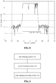
- a group of generated peak clipping coefficient which may be the peak clipping coefficient have the bandwidth of 30MHZ, may be used in TD or LTE, or the mixture thereof, if only the bandwidth and speed are matched.
- the bandwidth of peak clipping coefficient may be 40MHZ, 30 MHZ, 50 MHZ, as shown in FIG. 3 , respectively, although the carrier waves have different configuration, as long as the configuration of bandwidth of peak clipping coefficient and total bandwidth of signal are the same, the same group of peak clipping coefficient may be used.
- the peak clipping processing effect may be shown in the table below (the CCDF represents inverse cumulative probability distribution): Peak clipping coefficient configuration algorithmic program setting target PAR First carrier wave EVM Second carrier wave EVM Third carrier wave EVM Obtained CCDF by test Single coefficient 6.9 4.2 4.4 3.5 7.35 Combined coefficient 6.9 4.4 4.6 3.9 7.4
- the peak clipping processing using single peak clipping coefficient may improve EVM partly compared with using combined coefficient.
- the peak clipping processing to multiple carrier wave in the embodiment may be illustrated herein concisely.
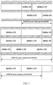
- the application have both TD carrier wave, and LTE carrier wave.
- multiple TD carrier wave generates a combined TD signal after the processing of interpolation filtering of td_h and the numerically controlled oscillator (NCO).
- multiple LTE carrier wave which are processed by inverse fast Fourier transform (IFFT) generates multiplex-processed LTE frequency band signal after the processing of interpolation filtering of td_h and the numerically controlled oscillator (NCO).
- IFFT inverse fast Fourier transform
- the combined TD signal and multiplex-processed LTE signal is processed by SUM process (multicarrier stack processing) after they are roughly filtered by HB filter. After that, peak cancellation crest factor reduction (PC-CFR) is performed.
- PC-CFR peak cancellation crest factor reduction
- the signal peak clipping coefficient specific to multiple carrier wave makes its effect on PC-CFR, that is according to single peak clipping coefficient, the PC-CFR is performed, and is output at last. That is, the digital up converter (DUC) performed after SUM process inputs a signal or high PAR inputs signal, the PC-CFR process is performed according to single peak clipping coefficient, and output CFR output signal/ low PAR output signal.
- DUC digital up converter
- high PAR input signal is taken as an example, DUC input signal may be referred to high PAR input signal.
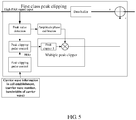
- the data is buffered, when the original input data sign bit is not changed, the peak value is detected. Then, in one aspect, a peak clipping pulse control is performed on the signal after peak value detection is performed by the generated multiple carrier wave single peak clipping coefficient, wherein as stated above, the single peak clipping coefficient may establish carrier wave information according to cell, including the carrier wave number and bandwidth generation of each carrier wave, the signal after peak clipping pulse control enters peak clipper; in another aspect, the signal after peak clipping pulse control is performed by amplitude phase calibration in peak value point. At last, the signal is output after peak clipping processing.
- the peak clipping bandwidth can be adjusted adaptively, the set of the peak clipping coefficient bandwidth and the establishment of cell is the corresponding carrier waves, the correspondence of frequency points and carrier wave number, after that, even if real-time user number reduces or carrier wave number reduces, the frequency spectrum of peak clipping coefficient is not changed any more, thusly, the peak clipping coefficient is both flexible and stable;
- the stopband rejection of the combined peak clipping coefficient is usually between 35 ⁇ 40dBc, which satisfies the composite requirement of system ACPR, EVM, and CCDF, and has the advantage of reducing EVM deterioration compared with conventional peak clipping coefficient; the combined peak clipping coefficient having relatively lower stopband rejection makes peak clipping even distributed in the whole frequency band, which reduces noise of
- a method for performing peak clipping to multiple carrier waves is disclosed specific to bandwidth of multiple carrier wave, wherein the peak clipping coefficient may satisfy the requirement from the system under different bandwidth to peak clipping performance, solves the problem in the conventional technology that the PAR is over large during multiple carrier wave superposing, and too many prototype coefficient is superposed, simplifies the generating process of peak clipping coefficient, reduces the deteriorate degree of EVM, and satisfies the requirement of ACPR, EVM and CCDF.
- FIG. 9 it is a block diagram showing the structure of a device for processing peak clipping to multiple carrier waves according to the third embodiment of the disclosure.
- the device for processing peak clipping to multiple carrier waves includes:
- the embodiment of the disclosure is designed directing at the maximum bandwidth of the configured multiple carrier waves, and according to the total signal bandwidth and the total occupied bandwidth of the carrier waves, generates a digital filter with set order, and then takes the filter coefficient of the digital filter as the peak clipping coefficient, and performs the peak clipping of the peak-to-average ratio signals to the carrier waves.
- the bandwidth defined by left frequency point and right frequency point of one group of multiple carrier waves is the same with that of another one or more groups of multiple carrier waves, then all of them may use the same peak clipping coefficient to perform the peak clipping on its peak-to-average ratio signals, and it is not necessary to pay attention to the multi-carrier wave within this group is TD carrier wave, or LTE carrier wave, or the mixture of the two.
- adopting a single peak clipping coefficient when multiple carrier waves are synthesized which simplifies the complexity of generating the peak clipping coefficient, reduces the deterioration degree of EVM, and also reduces the distortion degree of signals.
- the optimized multiple carrier wave peak clipping device includes: a first obtaining module 302, configured to, according to carrier wave number of configured multiple carrier waves, signal bandwidth and occupied bandwidth of each carrier wave, obtain total signal bandwidth and the total occupied bandwidth of the corresponding carrier waves; a second obtaining module 304, configured to, according to the total signal bandwidth and the total occupied bandwidth of the multiple carrier waves, generate a digital filter with set order, and obtain filter coefficient of the digital filter; a peak clipping processing module 306, configured to take the filter coefficient as a peak clipping coefficient, and use the peak clipping coefficient to perform peak clipping to the peak-to-average ratio signals of the carrier waves.
- the second obtaining module 304 when the second obtaining module 304 generates a digital filter with set order according to the total signal bandwidth and the total occupied bandwidth of the multiple carrier waves, it takes quotient of the total signal bandwidth of the carrier waves divided by the sampling frequency as the left frequency point of the digital filter, and taking the quotient of the total occupied bandwidth of the carrier waves divided by the sampling frequency as the right frequency point of the digital filter; and generates the digital filter with set order according to the left frequency point and the right frequency point.
- the second obtaining module 304 uses the first reduction coefficient to perform narrowing on the left frequency point and using the second reduction coefficient to perform narrowing on the right frequency point, respectively, to make the peak clipping noise bandwidth defined by the left frequency point and the right frequency point less than actual bandwidth; and generates the digital filter with set order according to the narrowed left frequency point and the right frequency point.
- the second obtaining module 304 when the second obtaining module 304 generates the digital filter with set order according to the left frequency point and the right frequency point, it takes the left frequency point, the right frequency point, and the set order as parameters, and uses firls function to generate finite impulse response (FIR) filter with set order.
- FIR finite impulse response
- the second obtaining module 304 uses kaiser window function to modify the generated FIR filter, and obtains the filter coefficient of the modified digital filter.
- the device or performing peak clipping to multiple carrier waves in the embodiment is used to realize the method or performing peak clipping to multiple carrier waves in the above embodiments, and has the beneficial effects of the corresponding method embodiments, which is not illustrated herein for concise purpose.
- the embodiment of the disclosure further discloses computer program, comprising computer readable codes, wherein when the computer readable codes are carried out on a server, the server executes the method for performing peak clipping to multiple carrier waves according to any one the embodiments above.
- the embodiment of the disclosure further disclose a medium which stores the computer program.
- the medium includes but not limited as mechanisms such as computer readable storage or information transmission ways.
- the medium includes read only memory (ROM), random access memory (RAM), Disk storage medium, optical storage medium, flash storage medium, transmission signals with the form of electric, light, sound and other forms (such as carrier wave, infrared signal, digital signal).
Landscapes
- Engineering & Computer Science (AREA)
- Signal Processing (AREA)
- Computer Networks & Wireless Communication (AREA)
- Power Engineering (AREA)
- Transmitters (AREA)
- Digital Transmission Methods That Use Modulated Carrier Waves (AREA)
Applications Claiming Priority (2)
| Application Number | Priority Date | Filing Date | Title |
|---|---|---|---|
| CN201310395688.3A CN103491045B (zh) | 2013-09-03 | 2013-09-03 | 多载波削峰处理方法与装置 |
| PCT/CN2014/085412 WO2015032290A1 (zh) | 2013-09-03 | 2014-08-28 | 多载波削峰处理方法与装置 |
Publications (2)
| Publication Number | Publication Date |
|---|---|
| EP3029902A1 true EP3029902A1 (de) | 2016-06-08 |
| EP3029902A4 EP3029902A4 (de) | 2017-05-31 |
Family
ID=49831010
Family Applications (1)
| Application Number | Title | Priority Date | Filing Date |
|---|---|---|---|
| EP14842931.9A Withdrawn EP3029902A4 (de) | 2013-09-03 | 2014-08-28 | Verfahren und vorrichtung zur verarbeitung von mehrträgerhöchstbelastungsreduktion |
Country Status (6)
| Country | Link |
|---|---|
| US (1) | US9497059B2 (de) |
| EP (1) | EP3029902A4 (de) |
| JP (1) | JP6259918B2 (de) |
| KR (1) | KR101831538B1 (de) |
| CN (1) | CN103491045B (de) |
| WO (1) | WO2015032290A1 (de) |
Cited By (1)
| Publication number | Priority date | Publication date | Assignee | Title |
|---|---|---|---|---|
| WO2019035749A1 (en) * | 2017-08-17 | 2019-02-21 | Telefonaktiebolaget Lm Ericsson (Publ) | COHERENT MULTIBAND PIC DETECTION |
Families Citing this family (12)
| Publication number | Priority date | Publication date | Assignee | Title |
|---|---|---|---|---|
| CN103491045B (zh) * | 2013-09-03 | 2016-08-24 | 大唐移动通信设备有限公司 | 多载波削峰处理方法与装置 |
| US10944606B2 (en) * | 2015-12-23 | 2021-03-09 | Telefonaktiebolaget Lm Ericsson (Publ) | Error scaling in crest factor reduction |
| US10084632B2 (en) * | 2016-09-22 | 2018-09-25 | Apple Inc. | System and method for peak-to-average power ratio reduction of OFDM signals via weighted gradient-based adaptive peak cancellation |
| WO2018137175A1 (en) * | 2017-01-25 | 2018-08-02 | Telefonaktiebolaget Lm Ericsson (Publ) | Method and apparatus for crest factor reduction |
| CN111357250B (zh) * | 2017-11-17 | 2022-05-10 | 瑞典爱立信有限公司 | 用于授权辅助接入无线电系统中的信号处理的设备和方法 |
| CN110048786B (zh) * | 2018-01-15 | 2022-03-01 | 天维讯达(北京)科技有限公司 | 一种无线电磁环境中信号频谱的峰值识别方法和装置 |
| WO2019231381A1 (en) * | 2018-06-01 | 2019-12-05 | Telefonaktiebolaget Lm Ericsson (Publ) | Ultra-wideband crest factor reduction |
| JP7405865B2 (ja) | 2019-04-15 | 2023-12-26 | 北京字節跳動網絡技術有限公司 | 非線形適応ループフィルタにおけるパラメータの時間的予測 |
| CN114006821B (zh) * | 2021-11-02 | 2024-04-02 | 北京金山云网络技术有限公司 | 一种业务范围调整方法、装置、电子设备及存储介质 |
| CN114500211B (zh) * | 2022-01-27 | 2023-03-24 | 重庆物奇微电子有限公司 | 高精度多相cfr系统及方法 |
| CN119586094A (zh) * | 2022-12-30 | 2025-03-07 | 华为技术有限公司 | 一种通信方法及相关设备 |
| CN119449147B (zh) * | 2024-11-07 | 2025-09-16 | 中国电子科技集团公司第二十九研究所 | 宽带射频通信信号evm改善方法、装置、设备、介质及程序产品 |
Family Cites Families (18)
| Publication number | Priority date | Publication date | Assignee | Title |
|---|---|---|---|---|
| US7430257B1 (en) * | 1998-02-12 | 2008-09-30 | Lot 41 Acquisition Foundation, Llc | Multicarrier sub-layer for direct sequence channel and multiple-access coding |
| US5955992A (en) * | 1998-02-12 | 1999-09-21 | Shattil; Steve J. | Frequency-shifted feedback cavity used as a phased array antenna controller and carrier interference multiple access spread-spectrum transmitter |
| US20030086507A1 (en) * | 2001-11-07 | 2003-05-08 | Jaehyeong Kim | Peak limiting architecture and method |
| US7983327B2 (en) * | 2006-08-28 | 2011-07-19 | Samsung Electronics Co., Ltd. | Method and system for providing digital adaptive predistortion in a subscriber station |
| JP4847838B2 (ja) * | 2006-10-13 | 2011-12-28 | 株式会社日立国際電気 | 送信機 |
| JP2009159055A (ja) * | 2007-12-25 | 2009-07-16 | Panasonic Corp | 送信装置及びピーク抑圧方法 |
| JP4558813B2 (ja) * | 2008-03-17 | 2010-10-06 | 株式会社日立国際電気 | 送信機 |
| CN101257481B (zh) * | 2008-04-22 | 2012-09-05 | 中兴通讯股份有限公司 | 一种预处理不连续配置多载波的削峰系统和方法 |
| US8068558B2 (en) * | 2008-12-17 | 2011-11-29 | Nortel Networks Limited | Selective peak power reduction |
| US8446202B2 (en) * | 2008-12-22 | 2013-05-21 | Nec Corporation | Power limiting circuit |
| CN101848182A (zh) * | 2009-03-25 | 2010-09-29 | 大唐移动通信设备有限公司 | 一种实现自适应削峰的方法和装置 |
| CN101662450B (zh) * | 2009-09-17 | 2012-03-07 | 京信通信系统(中国)有限公司 | 查表自适应削峰方法 |
| CN102111368B (zh) * | 2010-02-25 | 2013-07-24 | 电信科学技术研究院 | 一种信号波峰削除的方法及设备 |
| CN102299883B (zh) * | 2010-06-24 | 2014-02-19 | 大唐移动通信设备有限公司 | 一种宽频信号波峰削除方法及装置 |
| CN101938448B (zh) * | 2010-08-30 | 2013-11-06 | 京信通信系统(中国)有限公司 | 具有自动载波跟踪功能的cfr处理方法及装置、通信系统 |
| CN103001907B (zh) * | 2011-09-15 | 2015-08-19 | 华为技术有限公司 | 一种数字削峰方法和装置 |
| US9236899B2 (en) * | 2013-06-05 | 2016-01-12 | Telefonaktiebolaget L M Ericsson (Publ) | Crest factor reduction of inter-band carrier aggregated signals |
| CN103491045B (zh) * | 2013-09-03 | 2016-08-24 | 大唐移动通信设备有限公司 | 多载波削峰处理方法与装置 |
-
2013
- 2013-09-03 CN CN201310395688.3A patent/CN103491045B/zh active Active
-
2014
- 2014-08-28 JP JP2016539406A patent/JP6259918B2/ja active Active
- 2014-08-28 KR KR1020167008877A patent/KR101831538B1/ko active Active
- 2014-08-28 EP EP14842931.9A patent/EP3029902A4/de not_active Withdrawn
- 2014-08-28 WO PCT/CN2014/085412 patent/WO2015032290A1/zh not_active Ceased
- 2014-08-28 US US14/916,204 patent/US9497059B2/en active Active
Cited By (2)
| Publication number | Priority date | Publication date | Assignee | Title |
|---|---|---|---|---|
| WO2019035749A1 (en) * | 2017-08-17 | 2019-02-21 | Telefonaktiebolaget Lm Ericsson (Publ) | COHERENT MULTIBAND PIC DETECTION |
| US11082072B2 (en) | 2017-08-17 | 2021-08-03 | Telefonaktiebolaget Lm Ericsson (Publ) | Coherent multi band peak detection |
Also Published As
| Publication number | Publication date |
|---|---|
| JP2016533687A (ja) | 2016-10-27 |
| KR20160051868A (ko) | 2016-05-11 |
| US20160212002A1 (en) | 2016-07-21 |
| US9497059B2 (en) | 2016-11-15 |
| WO2015032290A1 (zh) | 2015-03-12 |
| CN103491045A (zh) | 2014-01-01 |
| KR101831538B1 (ko) | 2018-02-22 |
| JP6259918B2 (ja) | 2018-01-10 |
| EP3029902A4 (de) | 2017-05-31 |
| CN103491045B (zh) | 2016-08-24 |
Similar Documents
| Publication | Publication Date | Title |
|---|---|---|
| EP3029902A1 (de) | Verfahren und vorrichtung zur verarbeitung von mehrträgerhöchstbelastungsreduktion | |
| Bellanger | FS-FBMC: An alternative scheme for filter bank based multicarrier transmission | |
| Renfors et al. | Analysis and design of efficient and flexible fast-convolution based multirate filter banks | |
| EP2667508B1 (de) | Verfahren und Vorrichtung zur effizienten Frequenzdomänenimplementierung von zeitvariablen Filtern | |
| KR100926018B1 (ko) | 더 간단한 아날로그 필터링을 위해 ofdm 시스템에서ifft 를 사용한 디지털 업샘플링의 효율적인 이용 | |
| EP2348685B1 (de) | Verfahren und Vorrichtung zur Verringerung des Verhältnisses von Spitzenleistung zu Durchschnittsleistung mithilfe einer Spitzenfenstersfunktion | |
| US8467891B2 (en) | Method and system for efficient optimization of audio sampling rate conversion | |
| US20100217790A1 (en) | Method and apparatus for digital up-down conversion using infinite impulse response filter | |
| CN109525256B (zh) | 一种基于fpga的窄过渡带滤波器组的信道化发射结构 | |
| CN104660182B (zh) | 通信装置及减小波峰因数的方法 | |
| CN105337587B (zh) | 一种基于dft的非最大抽取系统综合滤波器组构造方法 | |
| Roy et al. | Design of narrow transition band digital filter: An analytical approach | |
| CN108293032B (zh) | 一种削波方法及装置 | |
| CN115299016B (zh) | 多速率波峰因子降低 | |
| CN102769595A (zh) | 降低apsk星座图调制papr的方法 | |
| CN104883157B (zh) | 一种可变子带数字滤波器 | |
| EP3567758A1 (de) | Digitaler synthese-kanalisierer mit kleinem platzbedarf für mehrere schmalbandige frequenzscheiben | |
| EP3206353A1 (de) | Filterbänke und verfahren zum betreiben von filterbänken | |
| CN107666453B (zh) | 发射器和相应的方法 | |
| CN1972179B (zh) | 一种多载波信号的产生方法 | |
| US20100310007A1 (en) | Filter Device | |
| CN201294546Y (zh) | 多载波系统降低峰均功率比的装置 | |
| Omidi et al. | PAPR reduction in OFDM systems: Polynomial-based compressing and iterative expanding | |
| Varahram et al. | A crest factor reduction scheme with optimum spacing peak cancellation for intra-band non-contiguous carrier aggregated OFDM signals | |
| Zakaria et al. | Wavelet based multicarrier modulation (MCM) systems: PAPR analysis |
Legal Events
| Date | Code | Title | Description |
|---|---|---|---|
| PUAI | Public reference made under article 153(3) epc to a published international application that has entered the european phase |
Free format text: ORIGINAL CODE: 0009012 |
|
| 17P | Request for examination filed |
Effective date: 20160303 |
|
| AK | Designated contracting states |
Kind code of ref document: A1 Designated state(s): AL AT BE BG CH CY CZ DE DK EE ES FI FR GB GR HR HU IE IS IT LI LT LU LV MC MK MT NL NO PL PT RO RS SE SI SK SM TR |
|
| AX | Request for extension of the european patent |
Extension state: BA ME |
|
| DAX | Request for extension of the european patent (deleted) | ||
| A4 | Supplementary search report drawn up and despatched |
Effective date: 20170503 |
|
| RIC1 | Information provided on ipc code assigned before grant |
Ipc: H04L 27/26 20060101AFI20170425BHEP Ipc: H04L 25/03 20060101ALI20170425BHEP |
|
| STAA | Information on the status of an ep patent application or granted ep patent |
Free format text: STATUS: EXAMINATION IS IN PROGRESS |
|
| 17Q | First examination report despatched |
Effective date: 20190930 |
|
| STAA | Information on the status of an ep patent application or granted ep patent |
Free format text: STATUS: THE APPLICATION HAS BEEN WITHDRAWN |
|
| 18W | Application withdrawn |
Effective date: 20200210 |