EP3029496A1 - Wire grid polarizer and method of fabricating the same - Google Patents
Wire grid polarizer and method of fabricating the same Download PDFInfo
- Publication number
- EP3029496A1 EP3029496A1 EP15170977.1A EP15170977A EP3029496A1 EP 3029496 A1 EP3029496 A1 EP 3029496A1 EP 15170977 A EP15170977 A EP 15170977A EP 3029496 A1 EP3029496 A1 EP 3029496A1
- Authority
- EP
- European Patent Office
- Prior art keywords
- substrate
- patterns
- grid polarizer
- wire grid
- recessed
- Prior art date
- Legal status (The legal status is an assumption and is not a legal conclusion. Google has not performed a legal analysis and makes no representation as to the accuracy of the status listed.)
- Withdrawn
Links
Images


Classifications
-
- G—PHYSICS
- G02—OPTICS
- G02B—OPTICAL ELEMENTS, SYSTEMS OR APPARATUS
- G02B5/00—Optical elements other than lenses
- G02B5/30—Polarising elements
- G02B5/3025—Polarisers, i.e. arrangements capable of producing a definite output polarisation state from an unpolarised input state
- G02B5/3058—Polarisers, i.e. arrangements capable of producing a definite output polarisation state from an unpolarised input state comprising electrically conductive elements, e.g. wire grids, conductive particles
-
- G—PHYSICS
- G02—OPTICS
- G02B—OPTICAL ELEMENTS, SYSTEMS OR APPARATUS
- G02B5/00—Optical elements other than lenses
- G02B5/30—Polarising elements
-
- C—CHEMISTRY; METALLURGY
- C23—COATING METALLIC MATERIAL; COATING MATERIAL WITH METALLIC MATERIAL; CHEMICAL SURFACE TREATMENT; DIFFUSION TREATMENT OF METALLIC MATERIAL; COATING BY VACUUM EVAPORATION, BY SPUTTERING, BY ION IMPLANTATION OR BY CHEMICAL VAPOUR DEPOSITION, IN GENERAL; INHIBITING CORROSION OF METALLIC MATERIAL OR INCRUSTATION IN GENERAL
- C23C—COATING METALLIC MATERIAL; COATING MATERIAL WITH METALLIC MATERIAL; SURFACE TREATMENT OF METALLIC MATERIAL BY DIFFUSION INTO THE SURFACE, BY CHEMICAL CONVERSION OR SUBSTITUTION; COATING BY VACUUM EVAPORATION, BY SPUTTERING, BY ION IMPLANTATION OR BY CHEMICAL VAPOUR DEPOSITION, IN GENERAL
- C23C16/00—Chemical coating by decomposition of gaseous compounds, without leaving reaction products of surface material in the coating, i.e. chemical vapour deposition [CVD] processes
- C23C16/01—Chemical coating by decomposition of gaseous compounds, without leaving reaction products of surface material in the coating, i.e. chemical vapour deposition [CVD] processes on temporary substrates, e.g. substrates subsequently removed by etching
-
- C—CHEMISTRY; METALLURGY
- C23—COATING METALLIC MATERIAL; COATING MATERIAL WITH METALLIC MATERIAL; CHEMICAL SURFACE TREATMENT; DIFFUSION TREATMENT OF METALLIC MATERIAL; COATING BY VACUUM EVAPORATION, BY SPUTTERING, BY ION IMPLANTATION OR BY CHEMICAL VAPOUR DEPOSITION, IN GENERAL; INHIBITING CORROSION OF METALLIC MATERIAL OR INCRUSTATION IN GENERAL
- C23C—COATING METALLIC MATERIAL; COATING MATERIAL WITH METALLIC MATERIAL; SURFACE TREATMENT OF METALLIC MATERIAL BY DIFFUSION INTO THE SURFACE, BY CHEMICAL CONVERSION OR SUBSTITUTION; COATING BY VACUUM EVAPORATION, BY SPUTTERING, BY ION IMPLANTATION OR BY CHEMICAL VAPOUR DEPOSITION, IN GENERAL
- C23C16/00—Chemical coating by decomposition of gaseous compounds, without leaving reaction products of surface material in the coating, i.e. chemical vapour deposition [CVD] processes
- C23C16/02—Pretreatment of the material to be coated
- C23C16/0227—Pretreatment of the material to be coated by cleaning or etching
-
- C—CHEMISTRY; METALLURGY
- C23—COATING METALLIC MATERIAL; COATING MATERIAL WITH METALLIC MATERIAL; CHEMICAL SURFACE TREATMENT; DIFFUSION TREATMENT OF METALLIC MATERIAL; COATING BY VACUUM EVAPORATION, BY SPUTTERING, BY ION IMPLANTATION OR BY CHEMICAL VAPOUR DEPOSITION, IN GENERAL; INHIBITING CORROSION OF METALLIC MATERIAL OR INCRUSTATION IN GENERAL
- C23C—COATING METALLIC MATERIAL; COATING MATERIAL WITH METALLIC MATERIAL; SURFACE TREATMENT OF METALLIC MATERIAL BY DIFFUSION INTO THE SURFACE, BY CHEMICAL CONVERSION OR SUBSTITUTION; COATING BY VACUUM EVAPORATION, BY SPUTTERING, BY ION IMPLANTATION OR BY CHEMICAL VAPOUR DEPOSITION, IN GENERAL
- C23C16/00—Chemical coating by decomposition of gaseous compounds, without leaving reaction products of surface material in the coating, i.e. chemical vapour deposition [CVD] processes
- C23C16/02—Pretreatment of the material to be coated
- C23C16/0254—Physical treatment to alter the texture of the surface, e.g. scratching or polishing
-
- C—CHEMISTRY; METALLURGY
- C23—COATING METALLIC MATERIAL; COATING MATERIAL WITH METALLIC MATERIAL; CHEMICAL SURFACE TREATMENT; DIFFUSION TREATMENT OF METALLIC MATERIAL; COATING BY VACUUM EVAPORATION, BY SPUTTERING, BY ION IMPLANTATION OR BY CHEMICAL VAPOUR DEPOSITION, IN GENERAL; INHIBITING CORROSION OF METALLIC MATERIAL OR INCRUSTATION IN GENERAL
- C23C—COATING METALLIC MATERIAL; COATING MATERIAL WITH METALLIC MATERIAL; SURFACE TREATMENT OF METALLIC MATERIAL BY DIFFUSION INTO THE SURFACE, BY CHEMICAL CONVERSION OR SUBSTITUTION; COATING BY VACUUM EVAPORATION, BY SPUTTERING, BY ION IMPLANTATION OR BY CHEMICAL VAPOUR DEPOSITION, IN GENERAL
- C23C16/00—Chemical coating by decomposition of gaseous compounds, without leaving reaction products of surface material in the coating, i.e. chemical vapour deposition [CVD] processes
- C23C16/56—After-treatment
-
- G—PHYSICS
- G02—OPTICS
- G02B—OPTICAL ELEMENTS, SYSTEMS OR APPARATUS
- G02B5/00—Optical elements other than lenses
- G02B5/30—Polarising elements
- G02B5/3008—Polarising elements comprising dielectric particles, e.g. birefringent crystals embedded in a matrix
-
- G—PHYSICS
- G02—OPTICS
- G02B—OPTICAL ELEMENTS, SYSTEMS OR APPARATUS
- G02B5/00—Optical elements other than lenses
- G02B5/30—Polarising elements
- G02B5/3016—Polarising elements involving passive liquid crystal elements
Definitions
- This application relates to a wire grid polarizer and a method of fabricating the same.
- a parallel conduction wire array in which conductor wires are arranged in parallel to one another to polarize certain light from electromagnetic waves is generally referred to as a wire grid polarizer.
- a wire grid polarizer In response to non-polarized light being incident, a wire grid polarizer with a smaller period than the wavelength of the incident light reflects polarized light parallel to a direction of the wires thereof, and transmits therethrough polarized light perpendicular to the direction of the wires thereof.
- a wire grid polarizer is more beneficial than an absorptive polarizer in that it allows reflected polarized light to be reused.
- Exemplary embodiments provide a wire grid polarizer with excellent processability, a display device having the wire grid polarizer, and a method of fabricating the wire grid polarizer.
- a wire grid polarizer comprising a substrate configured to have a plurality of recessed patterns disposed on a first surface thereof, a plurality of conductive wire patterns configured to be disposed in the recessed patterns, respectively, of the substrate, and an oxide layer configured to be disposed on the substrate and the conductive wire patterns.
- a wire grid polarizer comprising a substrate configured to have a plurality of first recessed patterns disposed on a first surface thereof and a second recessed pattern also disposed on the first surface thereof with a width larger than a width of the first recessed patterns, a plurality of conductive wire patterns configured to be disposed in the first recessed patterns, respectively, of the substrate, a reflective layer configured to be disposed in the second recessed pattern of the substrate, and an oxide layer configured to be disposed on the substrate, the conductive wire patterns and the reflective layer.
- a method of fabricating a wire grid polarizer comprising forming a plurality of recessed patterns on a first surface of a substrate, forming a conductive material layer on the first surface of the substrate to form a plurality of conductive wire patterns in the recessed patterns, respectively, and oxidizing part of the conductive material layer on the substrate.
- a method of fabricating a wire grid polarizer comprising forming a plurality of first recessed patterns and a second recessed pattern with a width larger than a width of the first recessed patterns on a first surface of a substrate, forming a conductive material layer on the first surface of the substrate to form a plurality of conductive wire patterns in the first recessed patterns, respectively, and a reflective layer in the second recessed pattern, and oxidizing part of the conductive material layer on the substrate.
- the term "on” that is used to designate that an element is on another element located on a different layer or a layer includes both a case where an element is located directly on another element or a layer and a case where an element is located on another element via another layer or still another element.
- first, second, and so forth are used to describe diverse constituent elements, such constituent elements are not limited by the terms. The terms are used only to discriminate a constituent element from another constituent element. Accordingly, in the following description, a first constituent element may be a second constituent element.
- FIG. 1 is a vertical cross-sectional view of a wire grid polarizer according to an exemplary embodiment.
- the wire grid polarizer may include a substrate 110, which has a plurality of recessed patterns formed thereon, a plurality of conductive wire patterns 121, which are disposed in the recessed patterns, respectively, of the substrate 110, and an oxide layer 123, which is disposed on the substrate 110 and the conductive wire patterns 121.
- the material of the substrate 110 may be appropriately selected in consideration of the purpose of use of the substrate 110 and the type of processing that the substrate 110 is to be subjected, as long as it allows the substrate 110 to transmit visible light therethrough.
- the substrate 110 may be formed of various polymers such as glass, quartz, acrylic, triacetyl cellulose (TAC), a cyclic olefin copolymer (COP), a cyclic olefin polymer (COC), polycarbonate (PC), polyethylenenaphthalate (PET), or polyethersulfone (PES), but the embodiments are not limited thereto.
- the substrate 110 may be formed of an optical film material with a certain degree of flexibility.
- a material with a low refractive index may be used to form the substrate 110 in consideration that the substrate 110 is disposed among the conductive wire patterns 121.
- the substrate 110 may have a refractive index of 1.0 to 1.7, but the embodiments are not limited thereto.
- the conductive wire patterns 121 may be arranged side-by-side on the substrate 110 with a regular period.
- the period is the center to center spacing of the conductive wire patterns 121.
- the conductive wire patterns 121 may need to be formed to have a period of at least about 200 nm or less to adequately perform polarization.
- the conductive wire patterns 121 may be formed to have a period of 120 nm or less to offer at least as high a polarization performance as a related-art polarizer, but the embodiments are not limited thereto.
- the conductive wire patterns 121 may be formed of any conductive material.
- the conductive wire patterns 121 may be formed of a metal material, and particularly, a metal selected from the group consisting of aluminum (Al), chromium (Cr), gold (Au), silver (Ag), copper (Cu), nickel (Ni), iron (Fe), tungsten (W), cobalt (Co) and molybdenum (Mo), or an alloy thereof, but the embodiments are not limited thereto.
- the width of the conductive wire patterns 121 may be smaller than the period of the conductive wire patterns 121, and may be set to a range in which the conductive wire patterns 121 may provide favorable polarization performance, for example, a range of about 10 nm to about 200 nm, but the embodiments are not limited thereto.
- the thickness of the conductive wire patterns 121 may be set to a range of about 10 nm to about 500 nm, but the embodiments are not limited thereto. As used herein, width is in the horizontal direction and thickness is in the vertical direction in the view of the figures.
- the oxide layer 123 may be formed on the substrate 110 and the conductive wire patterns 121.
- the oxide layer 123 may be formed of an oxide of the material of the conductive wire patterns 121.
- the oxide layer 123 may be formed to such a thickness that the conductive wire patterns 121 can be effectively insulated from wiring or thin-film transistor (TFT) devices to be formed during subsequent processes.
- the oxide layer 123 may be formed to a thickness of 100 nm to 1000 nm, in which case, the oxide layer 123 not only can effectively insulate the conductive wire patterns 121, but also can contribute to the processability and the thinness of a display device, but the embodiments are not limited thereto.
- the oxide layer 123 may be formed to a thickness of 200 nm to 300 nm.
- FIG. 2 is a vertical cross-sectional view of a wire grid polarizer according to another exemplary embodiment.
- the wire grid polarizer includes a supporting substrate 111, a substrate 110, which is formed on the supporting substrate 111 and has a plurality of recessed patterns formed thereon, a plurality of conductive wire patterns 121, which are disposed in the recessed patterns, respectively, of the substrate 110, and an oxide layer 123, which is disposed on the substrate 110 and the conductive wire patterns 121.
- the supporting substrate 111 may be formed on one surface of the substrate 110 to improve the supporting force or processability of the substrate 110.
- the recessed patterns of the substrate 110 are formed on the upper, e.g., first, surface of the substrate 110 and the supporting substrate 111 is provided on the lower, e.g., second, surface of the substrate 110 opposite the upper surface of the substrate 110.
- the material of the supporting substrate 111 may be appropriately selected in consideration of the purpose of use of the substrate 110 and the type of processing that the substrate 110 is to be subjected, as long as it allows the supporting substrate 111 to transmit visible light therethrough.
- the supporting substrate 111 may be formed of various polymers such as glass, quartz, acrylic, TAC, a COP, a COC, PC, PET, or PES, but the embodiments are not limited thereto.
- the rest of the wire grid polarizer of FIG. 2 is almost the same as that of the wire grid polarizer of FIG. 1 , and thus, a detailed description thereof will be omitted.
- FIG. 3 is a vertical cross-sectional view of a wire grid polarizer according to another exemplary embodiment.
- the wire grid polarizer includes a substrate 110, which has a plurality of recessed patterns formed thereon, a plurality of conductive wire patterns 121, which are disposed in the recessed patterns, respectively, of the substrate 110, and an oxide layer 123, which is disposed on the substrate 110 and the conductive wire patterns 121, and the oxide layer 123 may be relatively thinner in an area where it contacts the substrate 110 than in an area where it contacts the conductive wire patterns 121.
- the thickness of the conductive wire patterns 121 may be smaller than the depth of the recessed patterns of the substrate 110. Otherwise, the conductive wire patterns 121 may be connected to one another over the substrate 110, thereby deteriorating the optical properties of the wire grid polarizer of FIG. 3 .
- the rest of the wire grid polarizer of FIG. 3 is almost the same as that of the wire grid polarizer of FIG. 1 , and thus, a detailed description thereof will be omitted.
- FIG. 4 is a vertical cross-sectional view of a wire grid polarizer according to another exemplary embodiment.
- the wire grid polarizer includes a substrate 210, which has a plurality of first recessed patterns formed thereon with a relatively small width and a second recessed pattern also formed thereon with a relatively large width, a plurality of conductive wire patterns 221, which are disposed in the first recessed patterns, respectively, of the substrate 210, a reflective layer 222, which is disposed in the second recessed pattern of the substrate 210, and an oxide layer 223, which is disposed on the substrate 210, the conductive wire patterns 221, and the reflective layer 222.
- the reflective layer 222 may be formed in an area corresponding to a non-opening part of a display device having the wire grid polarizer of FIG. 4 .
- the reflective layer 222 may be formed in a wiring area or a transistor area, but the embodiments are not limited thereto.
- the reflective layer 222 may reflect light incident upon the non-opening part of the display device from a backlight unit (not illustrated), and may thus allow the light to be used in an opening part of the display device. Accordingly, the reflective layer 222 may improve the luminance of the display device.
- the rest of the wire grid polarizer of FIG. 4 is almost the same as that of the wire grid polarizer of FIG. 1 , and thus, a detailed description thereof will be omitted.
- FIG. 5 is a vertical cross-sectional view of a wire grid polarizer according to another exemplary embodiment.
- the wire grid polarizer includes a supporting substrate 211, a substrate 210, which is formed on the supporting substrate 211 and has a plurality of first recessed patterns formed thereon with a relatively small width and a second recessed pattern also formed thereon with a relatively large width, a plurality of conductive wire patterns 221, which are disposed in the first recessed patterns, respectively, of the substrate 210, a reflective layer 222, which is disposed in the second recessed pattern of the substrate 210, and an oxide layer 223, which is disposed on the substrate 210, the conductive wire patterns 221, and the reflective layer 222.
- the supporting substrate 211 may be formed on one surface of the substrate 210 to improve the supporting force or processability of the substrate 210.
- the material of the supporting substrate 211 may be appropriately selected in consideration of the purpose of use of the substrate 210 and the type of processing that the substrate 210 is to be subjected, as long as it allows the supporting substrate 211 to transmit visible light therethrough.
- the supporting substrate 211 may be formed of various polymers such as glass, quartz, acrylic, TAC, a COP, a COC, PC, PET, or PES, but the embodiments are not limited thereto.
- the rest of the wire grid polarizer of FIG. 5 is almost the same as that of the wire grid polarizer of FIG. 1 , and thus, a detailed description thereof will be omitted.
- FIG. 6 is a vertical cross-sectional view of a wire grid polarizer according to another exemplary embodiment.
- the wire grid polarizer includes a substrate 210, which has a plurality of first recessed patterns formed thereon with a relatively small width and a second recessed pattern also formed thereon with a relatively large width, a plurality of conductive wire patterns 221, which are disposed in the first recessed patterns, respectively, of the substrate 210, a reflective layer 222, which is disposed in the second recessed pattern of the substrate 210, and an oxide layer 223, which is disposed on the substrate 210, the conductive wire patterns 221, and the reflective layer 222.
- the oxide layer 223 may be relatively thinner in an area where it contacts the substrate 210 than in an area where it contacts the conductive wire patterns 221 and the reflective layer 222.
- the thickness of the conductive wire patterns 221 and the reflective layer 222 may be smaller than the depth of the recessed patterns of the substrate 210. Otherwise, the conductive wire patterns 221 may be connected to one another over the substrate 210, thereby deteriorating the optical properties of the wire grid polarizer of FIG. 6 .
- the rest of the wire grid polarizer of FIG. 6 is almost the same as that of the wire grid polarizer of FIG. 1 , and thus, a detailed description thereof will be omitted.
- FIGS. 7 to 13 are cross-sectional views illustrating a method of fabricating a wire grid polarizer, according to an exemplary embodiment.
- a plurality of recessed patterns 110a may be formed on one surface of the substrate 110.
- an imprint resin layer 130 may be formed on the substrate 110 as illustrated in FIG. 7 , and a patterned mold 131 may be pressed into the imprint resin layer 130 as illustrated in FIG. 8 .
- the imprint resin layer 130 may be cured with the mold 131 pressed thereinto. Since the substrate 110 is formed of a transparent material, the imprint resin layer 130 may be cured by an optical curing method, which involves the use of, for example, ultraviolet (UV) light.
- the imprint resin layer 130 may be cured by a thermal curing method or a combination of the optical curing method and the thermal curing method.
- the mold 131 and portions of the imprint resin layer 130 at the bottom of the mold 131 may be removed, thereby forming a plurality of mask patterns 130a as illustrated in FIGS. 9-10 .
- the substrate 110 may be etched by using the mask patterns 130a as a mask. As a result, the substrate 110 with the recessed patterns 110a may be obtained as illustrated in FIG. 11 .
- the formation of the recessed patterns 110a on the substrate 110 is not limited to the aforementioned imprinting method. Rather, any patterning method that can pattern the substrate 110 to any desired nano size may be used to form the recessed patterns 110a on the substrate 110. Examples of such nano-patterning methods include photoresist patterning, double patterning technology (DPT), and block copolymer (BCP) alignment patterning, but the embodiments are not limited thereto.
- DPT double patterning technology
- BCP block copolymer
- a conductive material layer 120 may be formed on the entire upper surface of the substrate 110 and within the recessed patterns 110a. Any method that can completely fill the recessed patterns 110a with the conductive material layer 120 may be used to form the conductive material layer 120.
- the conductive material layer 120 may be formed by chemical vapor deposition (CVD) or atomic layer deposition (ALD), but the embodiments are not limited thereto. Even a method that produces irregularities under particular conditions may be used after an adjustment of the conditions for deposition thereof, if the method can completely fill the recessed patterns 110a with the conductive material layer 120.
- the conductive material layer 120 may be oxidized, thereby forming an oxide layer 123 and a plurality of conductive wire patterns 121, which account for parts of the conductive material layer 120 that are not oxidized.
- Any oxidation method that can oxidize the conductive material layer 120 for example, anodic oxidation or plasma oxidation, may be used, but the embodiments are not limited thereto.
- the thickness of the oxide layer 123 may be adjusted by controlling the duration of oxidation or the intensity of the plasma.
- the conductive material layer 120 may be oxidized to the extent that the depth of oxidation reaches the substrate 110. Otherwise, the conductive wire patterns 121 may be connected to one another over the substrate 110, thereby deteriorating the optical properties of a wire grid polarizer.
- the oxide layer 123 may be formed in consideration of processing margin to be relatively thinner in an area where it contacts the substrate 110 than in an area where it contacts the conductive wire patterns 121.
- FIGS. 14 to 18 are cross-sectional views illustrating a method of fabricating a wire grid polarizer, according to another exemplary embodiment.
- a substrate precursor layer 100 may be formed on a supporting substrate 111 as illustrated in FIG. 14 , and a patterned mold 131 may be pressed into the substrate precursor layer 100 as illustrated in FIG. 15 .
- the substrate precursor layer 100 may be cured with the mold 131 pressed thereinto.
- An optical curing method, a thermal curing method or an opto-thermal curing method may be used to cure the substrate precursor layer 100.
- the mold 131 may be removed, thereby forming a substrate 110 with a plurality of recessed patterns 110a on one surface thereof and with the supporting substrate 111 on the other surface thereof as illustrated in FIG. 16 .
- the supporting substrate 111 may be removed. More specifically, after the patterning of the substrate 110, the supporting substrate 111 may be peeled off from the substrate 110.
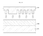
- FIGS. 19 to 25 are cross-sectional views illustrating a method of fabricating a wire grid polarizer, according to another exemplary embodiment.
- a plurality of first recessed patterns 210a and a second recessed pattern 210b may be formed on one surface of a substrate 210 as illustrated in FIG. 23 .
- an imprint resin layer 230 may be formed on the substrate 210 as illustrated in FIG. 19 , and a patterned mold 231 may be pressed into the imprint resin layer 230 as illustrated in FIG. 20 .
- the imprint resin layer 230 may be cured with the mold 231 pressed thereinto. Since the substrate 210 is formed of a transparent material, the imprint resin layer 230 may be cured by an optical curing method, which involves the use of, for example, UV light. Alternatively, the imprint resin layer 230 may be cured by a thermal curing method or a combination of the optical curing method and the thermal curing method.
- the mold 231 and portions of the imprint resin layer 230 at the bottom of the mold 231 may be removed, thereby forming a plurality of mask patterns 230a as illustrated in FIGS. 21-22 .
- the substrate 210 may be etched by using the mask patterns 230a as a mask. As a result, the substrate 210 with the first recessed patterns 210a and the second recessed pattern 210b may be obtained as illustrated in FIG. 23 .
- the formation of the first recessed patterns 210a and the second recessed pattern 210b on the substrate 210 is not limited to the aforementioned imprinting method. Rather, any patterning method that can pattern the substrate 210 to any desired nano size may be used to form the first recessed patterns 210a and the second recessed pattern 210b on the substrate 210. Examples of such nano-patterning methods include photoresist patterning, DPT, and BCP alignment patterning, but the embodiments are not limited thereto.
- a conductive material layer 220 may be formed on the entire upper surface of the substrate 210 and within the first recessed patterns 210a and the second recessed pattern 210b. Any method that can completely fill the first recessed patterns 210a and the second recessed pattern 210b with the conductive material layer 220 may be used to form the conductive material layer 220.
- the conductive material layer 220 may be formed by CVD or ALD, but the embodiments are not limited thereto. That is, even a method that produces irregularities under particular conditions may be used after an adjustment of the conditions for deposition thereof, if the method can completely fill the first recessed patterns 210a and the second recessed pattern 210b with the conductive material layer 220.
- the conductive material layer 220 may be oxidized, thereby forming an oxide layer 223 and a plurality of conductive wire patterns 221 and a reflective layer 222, which account for parts of the conductive material layer 220 that are not oxidized.
- Any oxidation method that can oxidize the conductive material layer 220 for example, anodic oxidation or plasma oxidation, may be used, but the embodiments are not limited thereto.
- the thickness of the oxide layer 223, i.e., the depth of oxidation, may be adjusted by controlling the duration of oxidation or the intensity of the plasma.
- the conductive material layer 220 may be oxidized to the extent that the depth of oxidation reaches the substrate 210. Otherwise, the conductive wire patterns 221 and the reflective layer 222 may be connected to one another over the substrate 210, thereby deteriorating the optical properties of a wire grid polarizer.
- the oxide layer 223 may be formed in consideration of processing margin to be relatively thinner in an area where it contacts the substrate 210 than in an area where it contacts the conductive wire patterns 221 and the reflective layer 222.
- FIGS. 26 to 30 are cross-sectional views illustrating a method of fabricating a wire grid polarizer, according to another exemplary embodiment.
- a substrate precursor layer 200 may be formed on a supporting substrate 211 as illustrated in FIG. 26 , and a patterned mold 231 may be pressed into the substrate precursor layer 200 as illustrated in FIG. 27 .
- the substrate precursor layer 200 may be cured with the mold 231 pressed thereinto.
- An optical curing method, a thermal curing method or an opto-thermal curing method may be used to cure the substrate precursor layer 200.
- the mold 231 may be removed, thereby forming a substrate 210 with a plurality of first recessed patterns 210a and a second recessed pattern 210b on one surface thereof and with the supporting substrate 211 on the other surface thereof as illustrated in FIG. 28 .
- the supporting substrate 211 may be removed. More specifically, after the patterning of the substrate 210, the supporting substrate 211 may be peeled off from the substrate 210.
Abstract
A wire grid polarizer and a method of fabricating a wire grid polarizer are provided. The wire grid polarizer comprises a substrate (110) configured to have a plurality ot recessed patterns (110a) disposed on a first surface thereof, a plurality of conductive wire patterns (121) configured to be disposed in the recessed patterns, respectively, of the substrate, and an oxide layer (123) configured to be disposed on the substrate and the conductive wire patterns.
Description
- This application claims priority to Korean Patent Application No.
10-2014-0173928 filed on December 05, 2014 - This application relates to a wire grid polarizer and a method of fabricating the same.
- A parallel conduction wire array in which conductor wires are arranged in parallel to one another to polarize certain light from electromagnetic waves is generally referred to as a wire grid polarizer.
- In response to non-polarized light being incident, a wire grid polarizer with a smaller period than the wavelength of the incident light reflects polarized light parallel to a direction of the wires thereof, and transmits therethrough polarized light perpendicular to the direction of the wires thereof. A wire grid polarizer is more beneficial than an absorptive polarizer in that it allows reflected polarized light to be reused.
- Exemplary embodiments provide a wire grid polarizer with excellent processability, a display device having the wire grid polarizer, and a method of fabricating the wire grid polarizer.
- However, exemplary embodiments are not restricted to those set forth herein. The above and other exemplary embodiments will become more apparent to one of ordinary skill in the art to which the application pertains by referencing the detailed description given below.
- According to an exemplary embodiment, there is provided a wire grid polarizer, comprising a substrate configured to have a plurality of recessed patterns disposed on a first surface thereof, a plurality of conductive wire patterns configured to be disposed in the recessed patterns, respectively, of the substrate, and an oxide layer configured to be disposed on the substrate and the conductive wire patterns.
- According to another exemplary embodiment, there is provided a wire grid polarizer, comprising a substrate configured to have a plurality of first recessed patterns disposed on a first surface thereof and a second recessed pattern also disposed on the first surface thereof with a width larger than a width of the first recessed patterns, a plurality of conductive wire patterns configured to be disposed in the first recessed patterns, respectively, of the substrate, a reflective layer configured to be disposed in the second recessed pattern of the substrate, and an oxide layer configured to be disposed on the substrate, the conductive wire patterns and the reflective layer.
- According to still another exemplary embodiment, there is provided a method of fabricating a wire grid polarizer, the method comprising forming a plurality of recessed patterns on a first surface of a substrate, forming a conductive material layer on the first surface of the substrate to form a plurality of conductive wire patterns in the recessed patterns, respectively, and oxidizing part of the conductive material layer on the substrate.
- According to still another exemplary embodiment, there is provided a method of fabricating a wire grid polarizer, the method comprising forming a plurality of first recessed patterns and a second recessed pattern with a width larger than a width of the first recessed patterns on a first surface of a substrate, forming a conductive material layer on the first surface of the substrate to form a plurality of conductive wire patterns in the first recessed patterns, respectively, and a reflective layer in the second recessed pattern, and oxidizing part of the conductive material layer on the substrate.
- According to the exemplary embodiments, it is possible to provide a wire grid polarizer with excellent processability.
- Other features and exemplary embodiments will be apparent from the following detailed description, the drawings, and the claims.
-
-
FIG. 1 is a vertical cross-sectional view of a wire grid polarizer according to an exemplary embodiment. -
FIG. 2 is a vertical cross-sectional view of a wire grid polarizer according to another exemplary embodiment. -
FIG. 3 is a vertical cross-sectional view of a wire grid polarizer according to another exemplary embodiment. -
FIG. 4 is a vertical cross-sectional view of a wire grid polarizer according to another exemplary embodiment. -
FIG. 5 is a vertical cross-sectional view of a wire grid polarizer according to another exemplary embodiment. -
FIG. 6 is a vertical cross-sectional view of a wire grid polarizer according to another exemplary embodiment. -
FIGS. 7 ,8 ,9 ,10 ,11 ,12 and13 are cross-sectional views illustrating a method of fabricating a wire grid polarizer, according to an exemplary embodiment. -
FIGS. 14 ,15 ,16 ,17 , and18 are cross-sectional views illustrating a method of fabricating a wire grid polarizer, according to another exemplary embodiment. -
FIGS. 19 ,20 ,21 ,22 ,23 ,24 , and25 are cross-sectional views illustrating a method of fabricating a wire grid polarizer, according to another exemplary embodiment. -
FIGS. 26 ,27 ,28 ,29 , and30 are cross-sectional views illustrating a method of fabricating a wire grid polarizer, according to another exemplary embodiment. - The aspects and features of the inventive concept and methods for achieving the aspects and features will be apparent by referring to the embodiments to be described in detail with reference to the accompanying drawings. However, the inventive concept is not limited to the embodiments disclosed hereinafter, but can be implemented in diverse forms. The matters defined in the description, such as the detailed construction and elements, are nothing but specific details provided to assist those of ordinary skill in the art in a comprehensive understanding of the inventive concept, and the inventive concept is only defined within the scope of the appended claims. In the entire description, the same reference numerals are used for the same elements across various figures. In the drawings, sizes and relative sizes of layers and areas may be exaggerated for clarity in explanation.
- The term "on" that is used to designate that an element is on another element located on a different layer or a layer includes both a case where an element is located directly on another element or a layer and a case where an element is located on another element via another layer or still another element.
- Although the terms "first, second, and so forth" are used to describe diverse constituent elements, such constituent elements are not limited by the terms. The terms are used only to discriminate a constituent element from another constituent element. Accordingly, in the following description, a first constituent element may be a second constituent element.
- Exemplary embodiments will hereinafter be described with reference to the accompanying drawings.
-
FIG. 1 is a vertical cross-sectional view of a wire grid polarizer according to an exemplary embodiment. - Referring to
FIG. 1 , the wire grid polarizer according to an exemplary embodiment may include asubstrate 110, which has a plurality of recessed patterns formed thereon, a plurality ofconductive wire patterns 121, which are disposed in the recessed patterns, respectively, of thesubstrate 110, and anoxide layer 123, which is disposed on thesubstrate 110 and theconductive wire patterns 121. - The material of the
substrate 110 may be appropriately selected in consideration of the purpose of use of thesubstrate 110 and the type of processing that thesubstrate 110 is to be subjected, as long as it allows thesubstrate 110 to transmit visible light therethrough. In an exemplary embodiment, thesubstrate 110 may be formed of various polymers such as glass, quartz, acrylic, triacetyl cellulose (TAC), a cyclic olefin copolymer (COP), a cyclic olefin polymer (COC), polycarbonate (PC), polyethylenenaphthalate (PET), or polyethersulfone (PES), but the embodiments are not limited thereto. Thesubstrate 110 may be formed of an optical film material with a certain degree of flexibility. - To achieve desired polarization properties, a material with a low refractive index may be used to form the
substrate 110 in consideration that thesubstrate 110 is disposed among theconductive wire patterns 121. In an exemplary embodiment, thesubstrate 110 may have a refractive index of 1.0 to 1.7, but the embodiments are not limited thereto. - The
conductive wire patterns 121 may be arranged side-by-side on thesubstrate 110 with a regular period. The period is the center to center spacing of theconductive wire patterns 121. The shorter the period of theconductive wire patterns 121, the higher the polarized light extinction ratio of theconductive wire patterns 121 with respect to the wavelength of incident light, but the more difficult it becomes to fabricate theconductive wire patterns 121. Visible light generally falls within the range of wavelengths of about 380 nm to about 780 nm. In order for the wire grid polarizer according to an exemplary embodiment to have a high extinction ratio with respect to light of the three primary colors (i.e., red (R), green (G) and blue (B)) of light, theconductive wire patterns 121 may need to be formed to have a period of at least about 200 nm or less to adequately perform polarization. Theconductive wire patterns 121 may be formed to have a period of 120 nm or less to offer at least as high a polarization performance as a related-art polarizer, but the embodiments are not limited thereto. - The
conductive wire patterns 121 may be formed of any conductive material. In an exemplary embodiment, theconductive wire patterns 121 may be formed of a metal material, and particularly, a metal selected from the group consisting of aluminum (Al), chromium (Cr), gold (Au), silver (Ag), copper (Cu), nickel (Ni), iron (Fe), tungsten (W), cobalt (Co) and molybdenum (Mo), or an alloy thereof, but the embodiments are not limited thereto. - The width of the
conductive wire patterns 121 may be smaller than the period of theconductive wire patterns 121, and may be set to a range in which theconductive wire patterns 121 may provide favorable polarization performance, for example, a range of about 10 nm to about 200 nm, but the embodiments are not limited thereto. The thickness of theconductive wire patterns 121 may be set to a range of about 10 nm to about 500 nm, but the embodiments are not limited thereto. As used herein, width is in the horizontal direction and thickness is in the vertical direction in the view of the figures. - The
oxide layer 123 may be formed on thesubstrate 110 and theconductive wire patterns 121. In an exemplary embodiment, theoxide layer 123 may be formed of an oxide of the material of theconductive wire patterns 121. - The
oxide layer 123 may be formed to such a thickness that theconductive wire patterns 121 can be effectively insulated from wiring or thin-film transistor (TFT) devices to be formed during subsequent processes. In an exemplary embodiment, theoxide layer 123 may be formed to a thickness of 100 nm to 1000 nm, in which case, theoxide layer 123 not only can effectively insulate theconductive wire patterns 121, but also can contribute to the processability and the thinness of a display device, but the embodiments are not limited thereto. In another exemplary embodiment, theoxide layer 123 may be formed to a thickness of 200 nm to 300 nm. -
FIG. 2 is a vertical cross-sectional view of a wire grid polarizer according to another exemplary embodiment. - Referring to
FIG. 2 , the wire grid polarizer according to another exemplary embodiment includes a supportingsubstrate 111, asubstrate 110, which is formed on the supportingsubstrate 111 and has a plurality of recessed patterns formed thereon, a plurality ofconductive wire patterns 121, which are disposed in the recessed patterns, respectively, of thesubstrate 110, and anoxide layer 123, which is disposed on thesubstrate 110 and theconductive wire patterns 121. - The supporting
substrate 111 may be formed on one surface of thesubstrate 110 to improve the supporting force or processability of thesubstrate 110. The recessed patterns of thesubstrate 110 are formed on the upper, e.g., first, surface of thesubstrate 110 and the supportingsubstrate 111 is provided on the lower, e.g., second, surface of thesubstrate 110 opposite the upper surface of thesubstrate 110. - The material of the supporting
substrate 111 may be appropriately selected in consideration of the purpose of use of thesubstrate 110 and the type of processing that thesubstrate 110 is to be subjected, as long as it allows the supportingsubstrate 111 to transmit visible light therethrough. In an exemplary embodiment, the supportingsubstrate 111 may be formed of various polymers such as glass, quartz, acrylic, TAC, a COP, a COC, PC, PET, or PES, but the embodiments are not limited thereto. - The rest of the wire grid polarizer of
FIG. 2 is almost the same as that of the wire grid polarizer ofFIG. 1 , and thus, a detailed description thereof will be omitted. -
FIG. 3 is a vertical cross-sectional view of a wire grid polarizer according to another exemplary embodiment. - Referring to
FIG. 3 , the wire grid polarizer according to another exemplary embodiment includes asubstrate 110, which has a plurality of recessed patterns formed thereon, a plurality ofconductive wire patterns 121, which are disposed in the recessed patterns, respectively, of thesubstrate 110, and anoxide layer 123, which is disposed on thesubstrate 110 and theconductive wire patterns 121, and theoxide layer 123 may be relatively thinner in an area where it contacts thesubstrate 110 than in an area where it contacts theconductive wire patterns 121. - That is, the thickness of the
conductive wire patterns 121 may be smaller than the depth of the recessed patterns of thesubstrate 110. Otherwise, theconductive wire patterns 121 may be connected to one another over thesubstrate 110, thereby deteriorating the optical properties of the wire grid polarizer ofFIG. 3 . - The rest of the wire grid polarizer of
FIG. 3 is almost the same as that of the wire grid polarizer ofFIG. 1 , and thus, a detailed description thereof will be omitted. -
FIG. 4 is a vertical cross-sectional view of a wire grid polarizer according to another exemplary embodiment. - Referring to
FIG. 4 , the wire grid polarizer according to another exemplary embodiment includes asubstrate 210, which has a plurality of first recessed patterns formed thereon with a relatively small width and a second recessed pattern also formed thereon with a relatively large width, a plurality ofconductive wire patterns 221, which are disposed in the first recessed patterns, respectively, of thesubstrate 210, areflective layer 222, which is disposed in the second recessed pattern of thesubstrate 210, and anoxide layer 223, which is disposed on thesubstrate 210, theconductive wire patterns 221, and thereflective layer 222. - The
reflective layer 222 may be formed in an area corresponding to a non-opening part of a display device having the wire grid polarizer ofFIG. 4 . For example, thereflective layer 222 may be formed in a wiring area or a transistor area, but the embodiments are not limited thereto. - The
reflective layer 222 may reflect light incident upon the non-opening part of the display device from a backlight unit (not illustrated), and may thus allow the light to be used in an opening part of the display device. Accordingly, thereflective layer 222 may improve the luminance of the display device. - The rest of the wire grid polarizer of
FIG. 4 is almost the same as that of the wire grid polarizer ofFIG. 1 , and thus, a detailed description thereof will be omitted. -
FIG. 5 is a vertical cross-sectional view of a wire grid polarizer according to another exemplary embodiment. - Referring to
FIG. 5 , the wire grid polarizer according to another exemplary embodiment includes a supportingsubstrate 211, asubstrate 210, which is formed on the supportingsubstrate 211 and has a plurality of first recessed patterns formed thereon with a relatively small width and a second recessed pattern also formed thereon with a relatively large width, a plurality ofconductive wire patterns 221, which are disposed in the first recessed patterns, respectively, of thesubstrate 210, areflective layer 222, which is disposed in the second recessed pattern of thesubstrate 210, and anoxide layer 223, which is disposed on thesubstrate 210, theconductive wire patterns 221, and thereflective layer 222. - The supporting
substrate 211 may be formed on one surface of thesubstrate 210 to improve the supporting force or processability of thesubstrate 210. - The material of the supporting
substrate 211 may be appropriately selected in consideration of the purpose of use of thesubstrate 210 and the type of processing that thesubstrate 210 is to be subjected, as long as it allows the supportingsubstrate 211 to transmit visible light therethrough. In an exemplary embodiment, the supportingsubstrate 211 may be formed of various polymers such as glass, quartz, acrylic, TAC, a COP, a COC, PC, PET, or PES, but the embodiments are not limited thereto. - The rest of the wire grid polarizer of
FIG. 5 is almost the same as that of the wire grid polarizer ofFIG. 1 , and thus, a detailed description thereof will be omitted. -
FIG. 6 is a vertical cross-sectional view of a wire grid polarizer according to another exemplary embodiment. - Referring to
FIG. 6 , the wire grid polarizer according to another exemplary embodiment includes asubstrate 210, which has a plurality of first recessed patterns formed thereon with a relatively small width and a second recessed pattern also formed thereon with a relatively large width, a plurality ofconductive wire patterns 221, which are disposed in the first recessed patterns, respectively, of thesubstrate 210, areflective layer 222, which is disposed in the second recessed pattern of thesubstrate 210, and anoxide layer 223, which is disposed on thesubstrate 210, theconductive wire patterns 221, and thereflective layer 222. Theoxide layer 223 may be relatively thinner in an area where it contacts thesubstrate 210 than in an area where it contacts theconductive wire patterns 221 and thereflective layer 222. - That is, the thickness of the
conductive wire patterns 221 and thereflective layer 222 may be smaller than the depth of the recessed patterns of thesubstrate 210. Otherwise, theconductive wire patterns 221 may be connected to one another over thesubstrate 210, thereby deteriorating the optical properties of the wire grid polarizer ofFIG. 6 . - The rest of the wire grid polarizer of
FIG. 6 is almost the same as that of the wire grid polarizer ofFIG. 1 , and thus, a detailed description thereof will be omitted. -
FIGS. 7 to 13 are cross-sectional views illustrating a method of fabricating a wire grid polarizer, according to an exemplary embodiment. - Referring to
FIGS. 7 to 11 , a plurality of recessedpatterns 110a (FIG. 11 ) may be formed on one surface of thesubstrate 110. - More specifically, an
imprint resin layer 130 may be formed on thesubstrate 110 as illustrated inFIG. 7 , and apatterned mold 131 may be pressed into theimprint resin layer 130 as illustrated inFIG. 8 . Theimprint resin layer 130 may be cured with themold 131 pressed thereinto. Since thesubstrate 110 is formed of a transparent material, theimprint resin layer 130 may be cured by an optical curing method, which involves the use of, for example, ultraviolet (UV) light. Alternatively, theimprint resin layer 130 may be cured by a thermal curing method or a combination of the optical curing method and the thermal curing method. - Thereafter, the
mold 131 and portions of theimprint resin layer 130 at the bottom of themold 131 may be removed, thereby forming a plurality ofmask patterns 130a as illustrated inFIGS. 9-10 . - Thereafter, the
substrate 110 may be etched by using themask patterns 130a as a mask. As a result, thesubstrate 110 with the recessedpatterns 110a may be obtained as illustrated inFIG. 11 . - However, the formation of the recessed
patterns 110a on thesubstrate 110 is not limited to the aforementioned imprinting method. Rather, any patterning method that can pattern thesubstrate 110 to any desired nano size may be used to form the recessedpatterns 110a on thesubstrate 110. Examples of such nano-patterning methods include photoresist patterning, double patterning technology (DPT), and block copolymer (BCP) alignment patterning, but the embodiments are not limited thereto. - Referring to
FIG. 12 , aconductive material layer 120 may be formed on the entire upper surface of thesubstrate 110 and within the recessedpatterns 110a. Any method that can completely fill the recessedpatterns 110a with theconductive material layer 120 may be used to form theconductive material layer 120. For example, theconductive material layer 120 may be formed by chemical vapor deposition (CVD) or atomic layer deposition (ALD), but the embodiments are not limited thereto. Even a method that produces irregularities under particular conditions may be used after an adjustment of the conditions for deposition thereof, if the method can completely fill the recessedpatterns 110a with theconductive material layer 120. - Referring to
FIG. 13 , theconductive material layer 120 may be oxidized, thereby forming anoxide layer 123 and a plurality ofconductive wire patterns 121, which account for parts of theconductive material layer 120 that are not oxidized. Any oxidation method that can oxidize theconductive material layer 120, for example, anodic oxidation or plasma oxidation, may be used, but the embodiments are not limited thereto. - The thickness of the
oxide layer 123, i.e., the depth of oxidation, may be adjusted by controlling the duration of oxidation or the intensity of the plasma. Theconductive material layer 120 may be oxidized to the extent that the depth of oxidation reaches thesubstrate 110. Otherwise, theconductive wire patterns 121 may be connected to one another over thesubstrate 110, thereby deteriorating the optical properties of a wire grid polarizer. In an exemplary embodiment, theoxide layer 123 may be formed in consideration of processing margin to be relatively thinner in an area where it contacts thesubstrate 110 than in an area where it contacts theconductive wire patterns 121. -
FIGS. 14 to 18 are cross-sectional views illustrating a method of fabricating a wire grid polarizer, according to another exemplary embodiment. - Referring to
FIGS. 14 to 18 , asubstrate precursor layer 100 may be formed on a supportingsubstrate 111 as illustrated inFIG. 14 , and apatterned mold 131 may be pressed into thesubstrate precursor layer 100 as illustrated inFIG. 15 . Thesubstrate precursor layer 100 may be cured with themold 131 pressed thereinto. An optical curing method, a thermal curing method or an opto-thermal curing method may be used to cure thesubstrate precursor layer 100. - Thereafter, the
mold 131 may be removed, thereby forming asubstrate 110 with a plurality of recessedpatterns 110a on one surface thereof and with the supportingsubstrate 111 on the other surface thereof as illustrated inFIG. 16 . - The rest of the method of fabricating a wire grid polarizer, according to the exemplary embodiment of
FIGS. 14 to 18 , is almost the same as that of the method of fabricating a wire grid polarizer, according to the exemplary embodiment ofFIGS. 7 and13 , and thus, a detailed description thereof will be omitted. - Even though not specifically illustrated in
FIGS. 14 to 18 , the supportingsubstrate 111 may be removed. More specifically, after the patterning of thesubstrate 110, the supportingsubstrate 111 may be peeled off from thesubstrate 110. -
FIGS. 19 to 25 are cross-sectional views illustrating a method of fabricating a wire grid polarizer, according to another exemplary embodiment. - Referring to
FIGS. 19 to 23 , a plurality of first recessedpatterns 210a and a second recessedpattern 210b may be formed on one surface of asubstrate 210 as illustrated inFIG. 23 . - More specifically, an
imprint resin layer 230 may be formed on thesubstrate 210 as illustrated inFIG. 19 , and apatterned mold 231 may be pressed into theimprint resin layer 230 as illustrated inFIG. 20 . Theimprint resin layer 230 may be cured with themold 231 pressed thereinto. Since thesubstrate 210 is formed of a transparent material, theimprint resin layer 230 may be cured by an optical curing method, which involves the use of, for example, UV light. Alternatively, theimprint resin layer 230 may be cured by a thermal curing method or a combination of the optical curing method and the thermal curing method. - Thereafter, the
mold 231 and portions of theimprint resin layer 230 at the bottom of themold 231 may be removed, thereby forming a plurality ofmask patterns 230a as illustrated inFIGS. 21-22 . - Thereafter, the
substrate 210 may be etched by using themask patterns 230a as a mask. As a result, thesubstrate 210 with the first recessedpatterns 210a and the second recessedpattern 210b may be obtained as illustrated inFIG. 23 . - However, the formation of the first recessed
patterns 210a and the second recessedpattern 210b on thesubstrate 210 is not limited to the aforementioned imprinting method. Rather, any patterning method that can pattern thesubstrate 210 to any desired nano size may be used to form the first recessedpatterns 210a and the second recessedpattern 210b on thesubstrate 210. Examples of such nano-patterning methods include photoresist patterning, DPT, and BCP alignment patterning, but the embodiments are not limited thereto. - Referring to
FIG. 24 , aconductive material layer 220 may be formed on the entire upper surface of thesubstrate 210 and within the first recessedpatterns 210a and the second recessedpattern 210b. Any method that can completely fill the first recessedpatterns 210a and the second recessedpattern 210b with theconductive material layer 220 may be used to form theconductive material layer 220. For example, theconductive material layer 220 may be formed by CVD or ALD, but the embodiments are not limited thereto. That is, even a method that produces irregularities under particular conditions may be used after an adjustment of the conditions for deposition thereof, if the method can completely fill the first recessedpatterns 210a and the second recessedpattern 210b with theconductive material layer 220. - Referring to
FIG. 25 , theconductive material layer 220 may be oxidized, thereby forming anoxide layer 223 and a plurality ofconductive wire patterns 221 and areflective layer 222, which account for parts of theconductive material layer 220 that are not oxidized. Any oxidation method that can oxidize theconductive material layer 220, for example, anodic oxidation or plasma oxidation, may be used, but the embodiments are not limited thereto. - The thickness of the
oxide layer 223, i.e., the depth of oxidation, may be adjusted by controlling the duration of oxidation or the intensity of the plasma. Theconductive material layer 220 may be oxidized to the extent that the depth of oxidation reaches thesubstrate 210. Otherwise, theconductive wire patterns 221 and thereflective layer 222 may be connected to one another over thesubstrate 210, thereby deteriorating the optical properties of a wire grid polarizer. In an exemplary embodiment, theoxide layer 223 may be formed in consideration of processing margin to be relatively thinner in an area where it contacts thesubstrate 210 than in an area where it contacts theconductive wire patterns 221 and thereflective layer 222. -
FIGS. 26 to 30 are cross-sectional views illustrating a method of fabricating a wire grid polarizer, according to another exemplary embodiment. - Referring to
FIGS. 26 to 30 , asubstrate precursor layer 200 may be formed on a supportingsubstrate 211 as illustrated inFIG. 26 , and apatterned mold 231 may be pressed into thesubstrate precursor layer 200 as illustrated inFIG. 27 . Thesubstrate precursor layer 200 may be cured with themold 231 pressed thereinto. An optical curing method, a thermal curing method or an opto-thermal curing method may be used to cure thesubstrate precursor layer 200. - Thereafter, the
mold 231 may be removed, thereby forming asubstrate 210 with a plurality of first recessedpatterns 210a and a second recessedpattern 210b on one surface thereof and with the supportingsubstrate 211 on the other surface thereof as illustrated inFIG. 28 . - The rest of the method of fabricating a wire grid polarizer, according to the exemplary embodiment of
FIGS. 26 to 30 , is almost the same as that of the method of fabricating a wire grid polarizer, according to the exemplary embodiment ofFIGS. 19 and25 , and thus, a detailed description thereof will be omitted. - Even though not specifically illustrated in
FIGS. 26 to 30 , the supportingsubstrate 211 may be removed. More specifically, after the patterning of thesubstrate 210, the supportingsubstrate 211 may be peeled off from thesubstrate 210. - However, the effects of the inventive concept are not restricted to the one set forth herein. The above and other effects of the inventive concept will become more apparent to one of daily skill in the art to which the inventive concept pertains by referencing the claims.
Claims (15)
- A wire grid polarizer, comprising:a substrate (110) configured to have a plurality of first recessed patterns disposed on a first surface thereof;a plurality of conductive wire patterns (121) configured to be disposed in the first recessed patterns, respectively, of the substrate (110); andan oxide layer configured to be disposed on the substrate (110) and the conductive wire patterns (121).
- The wire grid polarizer of claim 1, further comprising:a supporting substrate (111) configured to be provided on a second surface of the substrate (110).
- The wire grid polarizer of anyone of claims 1 to 2, wherein the substrate is further configured to have a refractive index of 1.0 to 1.7.
- The wire grid polarizer of anyone of claims 1 to 3, wherein the oxide layer is further configured to have a thickness of 100 nm to 1000 nm.
- The wire grid polarizer of anyone of claim 1s to 4, wherein the oxide layer is further configured to contact the substrate (110) and the conductive wire patterns (121).
- The wire grid polarizer of anyone of claims 1 to 5, wherein the oxide layer (123) is further configured to be thinner in an area where it contacts the substrate (110) than in an area where it contacts the conductive wire patterns (121).
- A wire grid polarizer of anyone of claims 1 to 6, comprising:a second recessed pattern also disposed on the first surface thereof with a width larger than a width of the first recessed patterns;a reflective layer (222) configured to be disposed in the second recessed pattern of the substrate (110); andthe oxide layer (123) configured to be disposed also on the reflective layer.
- The wire grid polarizer of anyone of claims 1 to 7, wherein the oxide layer (123) is further configured to contact the substrate (110), the conductive wire patterns (121), and the reflective layer (222).
- The wire grid polarizer of anyone of claims 1 to 8, wherein the oxide layer (223) is further configured to be thinner in an area where it contacts the substrate (110) than in an area where it contacts the conductive wire patterns (121).
- A method of fabricating a wire grid polarizer, the method comprising:forming a plurality of first recessed patterns (110a) on a first surface of a substrate (110);forming a conductive material layer on the first surface of the substrate (110) to form a plurality of conductive wire patterns (121) in the first recessed patterns (110a), respectively; andoxidizing part of the conductive material layer on the substrate (110).
- The method of claim 10, wherein the forming the conductive material layer, comprises using chemical vapor deposition (CVD) or atomic layer deposition (ALD).
- The method of claims 10 or 11, wherein the forming the recessed patterns, comprises:forming a pattern mask on the substrate; andforming the recessed patterns (110a) by using the pattern mask.
- The method of anyone of claims 10 tol2, wherein the forming the recessed patterns, comprises:applying a substrate precursor layer on a supporting substrate (111);imprinting the substrate precursor layer; andcuring the imprinted substrate precursor layer.
- The method of anyone of claims 10 to 13, further comprising:removing the supporting substrate (111).
- A method of fabricating a wire grid polarizer of anyone of claims 10 to 14,
forming a plurality of a second recessed patterns with a width larger than a width of the first recessed patterns (110a) on a first surface of a substrate (110);
forming a reflective layer (222) in the second recessed patterns.
Applications Claiming Priority (1)
| Application Number | Priority Date | Filing Date | Title |
|---|---|---|---|
| KR1020140173928A KR20160069048A (en) | 2014-12-05 | 2014-12-05 | Wire grid polarizer and method for fabricating the same |
Publications (1)
| Publication Number | Publication Date |
|---|---|
| EP3029496A1 true EP3029496A1 (en) | 2016-06-08 |
Family
ID=53434216
Family Applications (1)
| Application Number | Title | Priority Date | Filing Date |
|---|---|---|---|
| EP15170977.1A Withdrawn EP3029496A1 (en) | 2014-12-05 | 2015-06-08 | Wire grid polarizer and method of fabricating the same |
Country Status (4)
| Country | Link |
|---|---|
| US (1) | US20160161653A1 (en) |
| EP (1) | EP3029496A1 (en) |
| KR (1) | KR20160069048A (en) |
| CN (1) | CN105676334A (en) |
Families Citing this family (4)
| Publication number | Priority date | Publication date | Assignee | Title |
|---|---|---|---|---|
| KR20180035984A (en) * | 2016-09-29 | 2018-04-09 | 삼성디스플레이 주식회사 | Substrate for wire grid polarizer, wire grid polarizer, manufacturing method for wire grid polarizer and display device including wire grid polarizer |
| US20180164580A1 (en) * | 2016-12-12 | 2018-06-14 | Intel Corporation | Optical micro mirror arrays |
| JP2021004928A (en) * | 2019-06-25 | 2021-01-14 | 国立研究開発法人産業技術総合研究所 | Wire grid type polarizing element |
| KR20230020035A (en) * | 2021-08-02 | 2023-02-10 | 삼성디스플레이 주식회사 | Mask for Deposition |
Citations (4)
| Publication number | Priority date | Publication date | Assignee | Title |
|---|---|---|---|---|
| US20050088739A1 (en) * | 2003-10-23 | 2005-04-28 | Chih-Ho Chiu | Wire grid polarizer with double metal layers |
| US20060039069A1 (en) * | 2004-08-20 | 2006-02-23 | Sumitomo Chemical Company, Limited | Polarized light separating element embedded with thin metallic wire |
| US20090027773A1 (en) * | 2007-07-25 | 2009-01-29 | Seiko Epson Corporation | Wire grid type polarization element, manufacturing method thereof, liquid crystal device, and projection type display apparatus |
| US20100283957A1 (en) * | 2008-10-09 | 2010-11-11 | Sol-Grid, Llc | Polarized eyewear |
Family Cites Families (1)
| Publication number | Priority date | Publication date | Assignee | Title |
|---|---|---|---|---|
| KR20120072201A (en) * | 2010-12-23 | 2012-07-03 | 한국전자통신연구원 | Method for fabricating polarizer |
-
2014
- 2014-12-05 KR KR1020140173928A patent/KR20160069048A/en not_active Application Discontinuation
-
2015
- 2015-03-12 US US14/656,251 patent/US20160161653A1/en not_active Abandoned
- 2015-06-08 EP EP15170977.1A patent/EP3029496A1/en not_active Withdrawn
- 2015-08-31 CN CN201510547985.4A patent/CN105676334A/en active Pending
Patent Citations (4)
| Publication number | Priority date | Publication date | Assignee | Title |
|---|---|---|---|---|
| US20050088739A1 (en) * | 2003-10-23 | 2005-04-28 | Chih-Ho Chiu | Wire grid polarizer with double metal layers |
| US20060039069A1 (en) * | 2004-08-20 | 2006-02-23 | Sumitomo Chemical Company, Limited | Polarized light separating element embedded with thin metallic wire |
| US20090027773A1 (en) * | 2007-07-25 | 2009-01-29 | Seiko Epson Corporation | Wire grid type polarization element, manufacturing method thereof, liquid crystal device, and projection type display apparatus |
| US20100283957A1 (en) * | 2008-10-09 | 2010-11-11 | Sol-Grid, Llc | Polarized eyewear |
Also Published As
| Publication number | Publication date |
|---|---|
| CN105676334A (en) | 2016-06-15 |
| US20160161653A1 (en) | 2016-06-09 |
| KR20160069048A (en) | 2016-06-16 |
Similar Documents
| Publication | Publication Date | Title |
|---|---|---|
| US10509151B2 (en) | Wire grid polarizer, display device including the same, and method of fabricating the same | |
| US9939570B2 (en) | Wire grid polarizing plate, display device including the same, and method of fabricating said display device | |
| US8728331B2 (en) | Methods of fabricating imprint mold and of forming pattern using the imprint mold | |
| US20160124265A1 (en) | Polarizer, method for manufacturing polarizer and display panel | |
| KR102413970B1 (en) | Wire grid polarizer and method for fabricating the same | |
| EP3023821A1 (en) | Wire grid polarizer, display device including the same and method for fabricating the same | |
| EP3029496A1 (en) | Wire grid polarizer and method of fabricating the same | |
| KR102332038B1 (en) | Imprint lithography method, method for manufacturing master template using the method and master template manufactured by the method | |
| US9470829B2 (en) | Polarizing plate, TFT substrate including the polarizing plate, and method of manufacturing the polarizing plate | |
| KR20130024041A (en) | A wire grid polarizer, liquid crystal display including the same and method of manufacturing the wire grid polarizer | |
| KR20150093891A (en) | Manufacturing method of reflective polarizer plate and display device having reflective polarizer plate | |
| US20160033701A1 (en) | Wire grid polarizer and method of fabricating the same | |
| US9612379B2 (en) | Wire grid polarizer and method of fabricating the same | |
| US20160114502A1 (en) | Method of manufacturing mold and method of manufacturing polarizer | |
| US9488765B2 (en) | Wire grid polarizer and method of fabricating the same | |
| US20160170115A1 (en) | Wire grid polarizer and method of manufacturing the same | |
| KR20160065302A (en) | Wire grid polarizer and method for fabricating the same | |
| KR20160031612A (en) | Wire grid polarizer, display device including the same and method for fabricating the same | |
| KR102133211B1 (en) | Method for fabricating wire grid polarizer | |
| KR102241418B1 (en) | Wire grid polarizer and method for fabricating the same | |
| KR20130002528A (en) | Liquid crystal display apparatus and manufacturing method thereof | |
| KR20150133921A (en) | Method of manufacturing liquid crystal display panel |
Legal Events
| Date | Code | Title | Description |
|---|---|---|---|
| PUAI | Public reference made under article 153(3) epc to a published international application that has entered the european phase |
Free format text: ORIGINAL CODE: 0009012 |
|
| AK | Designated contracting states |
Kind code of ref document: A1 Designated state(s): AL AT BE BG CH CY CZ DE DK EE ES FI FR GB GR HR HU IE IS IT LI LT LU LV MC MK MT NL NO PL PT RO RS SE SI SK SM TR |
|
| AX | Request for extension of the european patent |
Extension state: BA ME |
|
| STAA | Information on the status of an ep patent application or granted ep patent |
Free format text: STATUS: THE APPLICATION IS DEEMED TO BE WITHDRAWN |
|
| 18D | Application deemed to be withdrawn |
Effective date: 20161209 |