EP3029093B1 - Production method for porous polyimide resin film, porous polyimide resin film, and separator employing same - Google Patents
Production method for porous polyimide resin film, porous polyimide resin film, and separator employing same Download PDFInfo
- Publication number
- EP3029093B1 EP3029093B1 EP14835087.9A EP14835087A EP3029093B1 EP 3029093 B1 EP3029093 B1 EP 3029093B1 EP 14835087 A EP14835087 A EP 14835087A EP 3029093 B1 EP3029093 B1 EP 3029093B1
- Authority
- EP
- European Patent Office
- Prior art keywords
- polyimide resin
- film
- porous polyimide
- fine particles
- resin film
- Prior art date
- Legal status (The legal status is an assumption and is not a legal conclusion. Google has not performed a legal analysis and makes no representation as to the accuracy of the status listed.)
- Active
Links
- 229920001721 polyimide Polymers 0.000 title claims description 212
- 239000009719 polyimide resin Substances 0.000 title claims description 116
- 238000004519 manufacturing process Methods 0.000 title claims description 20
- 239000010419 fine particle Substances 0.000 claims description 132
- 239000002131 composite material Substances 0.000 claims description 84
- 239000004642 Polyimide Substances 0.000 claims description 59
- 238000000034 method Methods 0.000 claims description 32
- 238000003486 chemical etching Methods 0.000 claims description 30
- 239000004962 Polyamide-imide Substances 0.000 claims description 26
- 229920002312 polyamide-imide Polymers 0.000 claims description 26
- 230000035699 permeability Effects 0.000 claims description 18
- VYPSYNLAJGMNEJ-UHFFFAOYSA-N Silicium dioxide Chemical compound O=[Si]=O VYPSYNLAJGMNEJ-UHFFFAOYSA-N 0.000 description 57
- HEMHJVSKTPXQMS-UHFFFAOYSA-M Sodium hydroxide Chemical compound [OH-].[Na+] HEMHJVSKTPXQMS-UHFFFAOYSA-M 0.000 description 54
- 239000002966 varnish Substances 0.000 description 52
- 239000004952 Polyamide Substances 0.000 description 45
- 229920002647 polyamide Polymers 0.000 description 45
- 239000002253 acid Substances 0.000 description 41
- 239000000243 solution Substances 0.000 description 40
- GTDPSWPPOUPBNX-UHFFFAOYSA-N ac1mqpva Chemical compound CC12C(=O)OC(=O)C1(C)C1(C)C2(C)C(=O)OC1=O GTDPSWPPOUPBNX-UHFFFAOYSA-N 0.000 description 36
- -1 LiPF6 Chemical class 0.000 description 35
- 239000003960 organic solvent Substances 0.000 description 30
- 239000011148 porous material Substances 0.000 description 28
- 150000004985 diamines Chemical class 0.000 description 24
- 230000000052 comparative effect Effects 0.000 description 21
- 125000006158 tetracarboxylic acid group Chemical group 0.000 description 21
- 239000000377 silicon dioxide Substances 0.000 description 20
- 239000002245 particle Substances 0.000 description 19
- WGTYBPLFGIVFAS-UHFFFAOYSA-M tetramethylammonium hydroxide Chemical compound [OH-].C[N+](C)(C)C WGTYBPLFGIVFAS-UHFFFAOYSA-M 0.000 description 18
- 230000015572 biosynthetic process Effects 0.000 description 17
- 229910052744 lithium Inorganic materials 0.000 description 17
- 238000010586 diagram Methods 0.000 description 16
- 239000002904 solvent Substances 0.000 description 16
- WHXSMMKQMYFTQS-UHFFFAOYSA-N Lithium Chemical compound [Li] WHXSMMKQMYFTQS-UHFFFAOYSA-N 0.000 description 15
- HBBGRARXTFLTSG-UHFFFAOYSA-N Lithium ion Chemical compound [Li+] HBBGRARXTFLTSG-UHFFFAOYSA-N 0.000 description 15
- 229910001416 lithium ion Inorganic materials 0.000 description 15
- 238000001354 calcination Methods 0.000 description 14
- 150000001875 compounds Chemical class 0.000 description 14
- 239000002270 dispersing agent Substances 0.000 description 13
- 239000000758 substrate Substances 0.000 description 13
- 238000011156 evaluation Methods 0.000 description 12
- PXHVJJICTQNCMI-UHFFFAOYSA-N Nickel Chemical compound [Ni] PXHVJJICTQNCMI-UHFFFAOYSA-N 0.000 description 11
- 239000004698 Polyethylene Substances 0.000 description 11
- 210000004027 cell Anatomy 0.000 description 11
- 239000003795 chemical substances by application Substances 0.000 description 11
- 239000008151 electrolyte solution Substances 0.000 description 11
- 229920000573 polyethylene Polymers 0.000 description 11
- LFQSCWFLJHTTHZ-UHFFFAOYSA-N Ethanol Chemical compound CCO LFQSCWFLJHTTHZ-UHFFFAOYSA-N 0.000 description 10
- 238000005530 etching Methods 0.000 description 10
- 239000000203 mixture Substances 0.000 description 10
- 239000007864 aqueous solution Substances 0.000 description 9
- 238000001035 drying Methods 0.000 description 9
- 239000011347 resin Substances 0.000 description 9
- 229920005989 resin Polymers 0.000 description 9
- 239000002356 single layer Substances 0.000 description 9
- 238000012360 testing method Methods 0.000 description 9
- XLYOFNOQVPJJNP-UHFFFAOYSA-N water Substances O XLYOFNOQVPJJNP-UHFFFAOYSA-N 0.000 description 9
- 229920002799 BoPET Polymers 0.000 description 8
- 238000006243 chemical reaction Methods 0.000 description 8
- 230000001965 increasing effect Effects 0.000 description 8
- 125000001997 phenyl group Chemical group [H]C1=C([H])C([H])=C(*)C([H])=C1[H] 0.000 description 8
- YEJRWHAVMIAJKC-UHFFFAOYSA-N 4-Butyrolactone Chemical compound O=C1CCCO1 YEJRWHAVMIAJKC-UHFFFAOYSA-N 0.000 description 7
- OKTJSMMVPCPJKN-UHFFFAOYSA-N Carbon Chemical compound [C] OKTJSMMVPCPJKN-UHFFFAOYSA-N 0.000 description 7
- 239000003513 alkali Substances 0.000 description 7
- 125000003118 aryl group Chemical group 0.000 description 7
- 229920002678 cellulose Polymers 0.000 description 7
- 235000010980 cellulose Nutrition 0.000 description 7
- 238000007600 charging Methods 0.000 description 7
- 210000001787 dendrite Anatomy 0.000 description 7
- 239000010410 layer Substances 0.000 description 7
- 238000002360 preparation method Methods 0.000 description 7
- RTZKZFJDLAIYFH-UHFFFAOYSA-N Diethyl ether Chemical compound CCOCC RTZKZFJDLAIYFH-UHFFFAOYSA-N 0.000 description 6
- XEEYBQQBJWHFJM-UHFFFAOYSA-N Iron Chemical compound [Fe] XEEYBQQBJWHFJM-UHFFFAOYSA-N 0.000 description 6
- OKKJLVBELUTLKV-UHFFFAOYSA-N Methanol Chemical compound OC OKKJLVBELUTLKV-UHFFFAOYSA-N 0.000 description 6
- ZMXDDKWLCZADIW-UHFFFAOYSA-N N,N-Dimethylformamide Chemical compound CN(C)C=O ZMXDDKWLCZADIW-UHFFFAOYSA-N 0.000 description 6
- SECXISVLQFMRJM-UHFFFAOYSA-N N-Methylpyrrolidone Chemical compound CN1CCCC1=O SECXISVLQFMRJM-UHFFFAOYSA-N 0.000 description 6
- ATUOYWHBWRKTHZ-UHFFFAOYSA-N Propane Chemical compound CCC ATUOYWHBWRKTHZ-UHFFFAOYSA-N 0.000 description 6
- 229910052782 aluminium Inorganic materials 0.000 description 6
- XAGFODPZIPBFFR-UHFFFAOYSA-N aluminium Chemical compound [Al] XAGFODPZIPBFFR-UHFFFAOYSA-N 0.000 description 6
- 239000001913 cellulose Substances 0.000 description 6
- 239000000178 monomer Substances 0.000 description 6
- 239000002798 polar solvent Substances 0.000 description 6
- 229920000642 polymer Polymers 0.000 description 6
- 230000009467 reduction Effects 0.000 description 6
- 239000010935 stainless steel Substances 0.000 description 6
- 229910001220 stainless steel Inorganic materials 0.000 description 6
- SRPWOOOHEPICQU-UHFFFAOYSA-N trimellitic anhydride Chemical compound OC(=O)C1=CC=C2C(=O)OC(=O)C2=C1 SRPWOOOHEPICQU-UHFFFAOYSA-N 0.000 description 6
- UFHFLCQGNIYNRP-UHFFFAOYSA-N Hydrogen Chemical compound [H][H] UFHFLCQGNIYNRP-UHFFFAOYSA-N 0.000 description 5
- 229920003171 Poly (ethylene oxide) Polymers 0.000 description 5
- 150000004984 aromatic diamines Chemical class 0.000 description 5
- OJIJEKBXJYRIBZ-UHFFFAOYSA-N cadmium nickel Chemical compound [Ni].[Cd] OJIJEKBXJYRIBZ-UHFFFAOYSA-N 0.000 description 5
- 230000008859 change Effects 0.000 description 5
- 235000014113 dietary fatty acids Nutrition 0.000 description 5
- 239000000194 fatty acid Substances 0.000 description 5
- 229930195729 fatty acid Natural products 0.000 description 5
- 125000000524 functional group Chemical group 0.000 description 5
- 238000010438 heat treatment Methods 0.000 description 5
- 239000001257 hydrogen Substances 0.000 description 5
- 229910052739 hydrogen Inorganic materials 0.000 description 5
- 230000014759 maintenance of location Effects 0.000 description 5
- 239000000463 material Substances 0.000 description 5
- 238000002156 mixing Methods 0.000 description 5
- 229910052759 nickel Inorganic materials 0.000 description 5
- 238000005979 thermal decomposition reaction Methods 0.000 description 5
- HLBLWEWZXPIGSM-UHFFFAOYSA-N 4-Aminophenyl ether Chemical compound C1=CC(N)=CC=C1OC1=CC=C(N)C=C1 HLBLWEWZXPIGSM-UHFFFAOYSA-N 0.000 description 4
- IJGRMHOSHXDMSA-UHFFFAOYSA-N Atomic nitrogen Chemical compound N#N IJGRMHOSHXDMSA-UHFFFAOYSA-N 0.000 description 4
- OAKJQQAXSVQMHS-UHFFFAOYSA-N Hydrazine Chemical compound NN OAKJQQAXSVQMHS-UHFFFAOYSA-N 0.000 description 4
- KFZMGEQAYNKOFK-UHFFFAOYSA-N Isopropanol Chemical compound CC(C)O KFZMGEQAYNKOFK-UHFFFAOYSA-N 0.000 description 4
- 229910001290 LiPF6 Inorganic materials 0.000 description 4
- FXHOOIRPVKKKFG-UHFFFAOYSA-N N,N-Dimethylacetamide Chemical compound CN(C)C(C)=O FXHOOIRPVKKKFG-UHFFFAOYSA-N 0.000 description 4
- KWYUFKZDYYNOTN-UHFFFAOYSA-M Potassium hydroxide Chemical compound [OH-].[K+] KWYUFKZDYYNOTN-UHFFFAOYSA-M 0.000 description 4
- 125000002947 alkylene group Chemical group 0.000 description 4
- 239000012752 auxiliary agent Substances 0.000 description 4
- 239000011230 binding agent Substances 0.000 description 4
- 238000009826 distribution Methods 0.000 description 4
- NAQMVNRVTILPCV-UHFFFAOYSA-N hexane-1,6-diamine Chemical compound NCCCCCCN NAQMVNRVTILPCV-UHFFFAOYSA-N 0.000 description 4
- 239000007788 liquid Substances 0.000 description 4
- 238000000053 physical method Methods 0.000 description 4
- 239000002344 surface layer Substances 0.000 description 4
- 238000005406 washing Methods 0.000 description 4
- VLDPXPPHXDGHEW-UHFFFAOYSA-N 1-chloro-2-dichlorophosphoryloxybenzene Chemical compound ClC1=CC=CC=C1OP(Cl)(Cl)=O VLDPXPPHXDGHEW-UHFFFAOYSA-N 0.000 description 3
- WEVYAHXRMPXWCK-UHFFFAOYSA-N Acetonitrile Chemical compound CC#N WEVYAHXRMPXWCK-UHFFFAOYSA-N 0.000 description 3
- CURLTUGMZLYLDI-UHFFFAOYSA-N Carbon dioxide Chemical compound O=C=O CURLTUGMZLYLDI-UHFFFAOYSA-N 0.000 description 3
- KMTRUDSVKNLOMY-UHFFFAOYSA-N Ethylene carbonate Chemical compound O=C1OCCO1 KMTRUDSVKNLOMY-UHFFFAOYSA-N 0.000 description 3
- 239000004743 Polypropylene Substances 0.000 description 3
- XUIMIQQOPSSXEZ-UHFFFAOYSA-N Silicon Chemical compound [Si] XUIMIQQOPSSXEZ-UHFFFAOYSA-N 0.000 description 3
- ZMANZCXQSJIPKH-UHFFFAOYSA-N Triethylamine Chemical compound CCN(CC)CC ZMANZCXQSJIPKH-UHFFFAOYSA-N 0.000 description 3
- 125000001931 aliphatic group Chemical group 0.000 description 3
- 150000005215 alkyl ethers Chemical class 0.000 description 3
- 229910052799 carbon Inorganic materials 0.000 description 3
- 239000003575 carbonaceous material Substances 0.000 description 3
- 235000019438 castor oil Nutrition 0.000 description 3
- 239000004359 castor oil Substances 0.000 description 3
- 238000000354 decomposition reaction Methods 0.000 description 3
- 125000005442 diisocyanate group Chemical group 0.000 description 3
- 238000007599 discharging Methods 0.000 description 3
- 150000004665 fatty acids Chemical class 0.000 description 3
- 239000011888 foil Substances 0.000 description 3
- 239000011521 glass Substances 0.000 description 3
- ZEMPKEQAKRGZGQ-XOQCFJPHSA-N glycerol triricinoleate Natural products CCCCCC[C@@H](O)CC=CCCCCCCCC(=O)OC[C@@H](COC(=O)CCCCCCCC=CC[C@@H](O)CCCCCC)OC(=O)CCCCCCCC=CC[C@H](O)CCCCCC ZEMPKEQAKRGZGQ-XOQCFJPHSA-N 0.000 description 3
- 230000006872 improvement Effects 0.000 description 3
- 229910052742 iron Inorganic materials 0.000 description 3
- 150000002596 lactones Chemical class 0.000 description 3
- 229910003002 lithium salt Inorganic materials 0.000 description 3
- 159000000002 lithium salts Chemical class 0.000 description 3
- QJGQUHMNIGDVPM-UHFFFAOYSA-N nitrogen group Chemical group [N] QJGQUHMNIGDVPM-UHFFFAOYSA-N 0.000 description 3
- 229920000620 organic polymer Polymers 0.000 description 3
- 150000004986 phenylenediamines Chemical class 0.000 description 3
- 229920003229 poly(methyl methacrylate) Polymers 0.000 description 3
- 238000006116 polymerization reaction Methods 0.000 description 3
- 239000004926 polymethyl methacrylate Substances 0.000 description 3
- 229920001155 polypropylene Polymers 0.000 description 3
- 239000007774 positive electrode material Substances 0.000 description 3
- 239000001294 propane Substances 0.000 description 3
- 239000002994 raw material Substances 0.000 description 3
- 150000003839 salts Chemical class 0.000 description 3
- 239000000523 sample Substances 0.000 description 3
- 239000010703 silicon Substances 0.000 description 3
- 229910052710 silicon Inorganic materials 0.000 description 3
- 238000005476 soldering Methods 0.000 description 3
- 238000003756 stirring Methods 0.000 description 3
- 239000000126 substance Substances 0.000 description 3
- 239000004094 surface-active agent Substances 0.000 description 3
- AVQQQNCBBIEMEU-UHFFFAOYSA-N 1,1,3,3-tetramethylurea Chemical compound CN(C)C(=O)N(C)C AVQQQNCBBIEMEU-UHFFFAOYSA-N 0.000 description 2
- WZCQRUWWHSTZEM-UHFFFAOYSA-N 1,3-phenylenediamine Chemical compound NC1=CC=CC(N)=C1 WZCQRUWWHSTZEM-UHFFFAOYSA-N 0.000 description 2
- ALQLPWJFHRMHIU-UHFFFAOYSA-N 1,4-diisocyanatobenzene Chemical compound O=C=NC1=CC=C(N=C=O)C=C1 ALQLPWJFHRMHIU-UHFFFAOYSA-N 0.000 description 2
- CBCKQZAAMUWICA-UHFFFAOYSA-N 1,4-phenylenediamine Chemical compound NC1=CC=C(N)C=C1 CBCKQZAAMUWICA-UHFFFAOYSA-N 0.000 description 2
- SEYKENDCALELBV-UHFFFAOYSA-N 1-N'-phenyl-2,3-dihydroindene-1,1-diamine Chemical class NC1(CCC2=CC=CC=C12)NC1=CC=CC=C1 SEYKENDCALELBV-UHFFFAOYSA-N 0.000 description 2
- VOZKAJLKRJDJLL-UHFFFAOYSA-N 2,4-diaminotoluene Chemical compound CC1=CC=C(N)C=C1N VOZKAJLKRJDJLL-UHFFFAOYSA-N 0.000 description 2
- MXPYJVUYLVNEBB-UHFFFAOYSA-N 2-[2-(2-carboxybenzoyl)oxycarbonylbenzoyl]oxycarbonylbenzoic acid Chemical compound OC(=O)C1=CC=CC=C1C(=O)OC(=O)C1=CC=CC=C1C(=O)OC(=O)C1=CC=CC=C1C(O)=O MXPYJVUYLVNEBB-UHFFFAOYSA-N 0.000 description 2
- XLLIQLLCWZCATF-UHFFFAOYSA-N 2-methoxyethyl acetate Chemical compound COCCOC(C)=O XLLIQLLCWZCATF-UHFFFAOYSA-N 0.000 description 2
- RUMACXVDVNRZJZ-UHFFFAOYSA-N 2-methylpropyl 2-methylprop-2-enoate Chemical compound CC(C)COC(=O)C(C)=C RUMACXVDVNRZJZ-UHFFFAOYSA-N 0.000 description 2
- DKKYOQYISDAQER-UHFFFAOYSA-N 3-[3-(3-aminophenoxy)phenoxy]aniline Chemical compound NC1=CC=CC(OC=2C=C(OC=3C=C(N)C=CC=3)C=CC=2)=C1 DKKYOQYISDAQER-UHFFFAOYSA-N 0.000 description 2
- UPMLOUAZCHDJJD-UHFFFAOYSA-N 4,4'-Diphenylmethane Diisocyanate Chemical compound C1=CC(N=C=O)=CC=C1CC1=CC=C(N=C=O)C=C1 UPMLOUAZCHDJJD-UHFFFAOYSA-N 0.000 description 2
- WUPRYUDHUFLKFL-UHFFFAOYSA-N 4-[3-(4-aminophenoxy)phenoxy]aniline Chemical compound C1=CC(N)=CC=C1OC1=CC=CC(OC=2C=CC(N)=CC=2)=C1 WUPRYUDHUFLKFL-UHFFFAOYSA-N 0.000 description 2
- JCRRFJIVUPSNTA-UHFFFAOYSA-N 4-[4-(4-aminophenoxy)phenoxy]aniline Chemical compound C1=CC(N)=CC=C1OC(C=C1)=CC=C1OC1=CC=C(N)C=C1 JCRRFJIVUPSNTA-UHFFFAOYSA-N 0.000 description 2
- HYDATEKARGDBKU-UHFFFAOYSA-N 4-[4-[4-(4-aminophenoxy)phenyl]phenoxy]aniline Chemical group C1=CC(N)=CC=C1OC1=CC=C(C=2C=CC(OC=3C=CC(N)=CC=3)=CC=2)C=C1 HYDATEKARGDBKU-UHFFFAOYSA-N 0.000 description 2
- NVKGJHAQGWCWDI-UHFFFAOYSA-N 4-[4-amino-2-(trifluoromethyl)phenyl]-3-(trifluoromethyl)aniline Chemical group FC(F)(F)C1=CC(N)=CC=C1C1=CC=C(N)C=C1C(F)(F)F NVKGJHAQGWCWDI-UHFFFAOYSA-N 0.000 description 2
- SKKKJNPBIGQNEJ-UHFFFAOYSA-N 9h-fluorene-1,9-diamine Chemical class C1=CC(N)=C2C(N)C3=CC=CC=C3C2=C1 SKKKJNPBIGQNEJ-UHFFFAOYSA-N 0.000 description 2
- XKRFYHLGVUSROY-UHFFFAOYSA-N Argon Chemical compound [Ar] XKRFYHLGVUSROY-UHFFFAOYSA-N 0.000 description 2
- 235000013162 Cocos nucifera Nutrition 0.000 description 2
- 244000060011 Cocos nucifera Species 0.000 description 2
- RYGMFSIKBFXOCR-UHFFFAOYSA-N Copper Chemical compound [Cu] RYGMFSIKBFXOCR-UHFFFAOYSA-N 0.000 description 2
- OIFBSDVPJOWBCH-UHFFFAOYSA-N Diethyl carbonate Chemical compound CCOC(=O)OCC OIFBSDVPJOWBCH-UHFFFAOYSA-N 0.000 description 2
- IAZDPXIOMUYVGZ-UHFFFAOYSA-N Dimethylsulphoxide Chemical compound CS(C)=O IAZDPXIOMUYVGZ-UHFFFAOYSA-N 0.000 description 2
- QUSNBJAOOMFDIB-UHFFFAOYSA-N Ethylamine Chemical compound CCN QUSNBJAOOMFDIB-UHFFFAOYSA-N 0.000 description 2
- PIICEJLVQHRZGT-UHFFFAOYSA-N Ethylenediamine Chemical compound NCCN PIICEJLVQHRZGT-UHFFFAOYSA-N 0.000 description 2
- VVQNEPGJFQJSBK-UHFFFAOYSA-N Methyl methacrylate Chemical compound COC(=O)C(C)=C VVQNEPGJFQJSBK-UHFFFAOYSA-N 0.000 description 2
- SUAKHGWARZSWIH-UHFFFAOYSA-N N,N‐diethylformamide Chemical compound CCN(CC)C=O SUAKHGWARZSWIH-UHFFFAOYSA-N 0.000 description 2
- ZWXPDGCFMMFNRW-UHFFFAOYSA-N N-methylcaprolactam Chemical compound CN1CCCCCC1=O ZWXPDGCFMMFNRW-UHFFFAOYSA-N 0.000 description 2
- 229910019142 PO4 Inorganic materials 0.000 description 2
- 239000002033 PVDF binder Substances 0.000 description 2
- NQRYJNQNLNOLGT-UHFFFAOYSA-N Piperidine Chemical compound C1CCNCC1 NQRYJNQNLNOLGT-UHFFFAOYSA-N 0.000 description 2
- CDBYLPFSWZWCQE-UHFFFAOYSA-L Sodium Carbonate Chemical compound [Na+].[Na+].[O-]C([O-])=O CDBYLPFSWZWCQE-UHFFFAOYSA-L 0.000 description 2
- 239000004115 Sodium Silicate Substances 0.000 description 2
- WYURNTSHIVDZCO-UHFFFAOYSA-N Tetrahydrofuran Chemical compound C1CCOC1 WYURNTSHIVDZCO-UHFFFAOYSA-N 0.000 description 2
- LWZFANDGMFTDAV-BURFUSLBSA-N [(2r)-2-[(2r,3r,4s)-3,4-dihydroxyoxolan-2-yl]-2-hydroxyethyl] dodecanoate Chemical compound CCCCCCCCCCCC(=O)OC[C@@H](O)[C@H]1OC[C@H](O)[C@H]1O LWZFANDGMFTDAV-BURFUSLBSA-N 0.000 description 2
- 239000006230 acetylene black Substances 0.000 description 2
- 150000007513 acids Chemical class 0.000 description 2
- 230000002776 aggregation Effects 0.000 description 2
- 238000004220 aggregation Methods 0.000 description 2
- 125000000217 alkyl group Chemical group 0.000 description 2
- 239000004411 aluminium Substances 0.000 description 2
- PNEYBMLMFCGWSK-UHFFFAOYSA-N aluminium oxide Inorganic materials [O-2].[O-2].[O-2].[Al+3].[Al+3] PNEYBMLMFCGWSK-UHFFFAOYSA-N 0.000 description 2
- 150000001408 amides Chemical class 0.000 description 2
- 239000003125 aqueous solvent Substances 0.000 description 2
- QVGXLLKOCUKJST-UHFFFAOYSA-N atomic oxygen Chemical compound [O] QVGXLLKOCUKJST-UHFFFAOYSA-N 0.000 description 2
- HFACYLZERDEVSX-UHFFFAOYSA-N benzidine Chemical group C1=CC(N)=CC=C1C1=CC=C(N)C=C1 HFACYLZERDEVSX-UHFFFAOYSA-N 0.000 description 2
- WKDNYTOXBCRNPV-UHFFFAOYSA-N bpda Chemical compound C1=C2C(=O)OC(=O)C2=CC(C=2C=C3C(=O)OC(C3=CC=2)=O)=C1 WKDNYTOXBCRNPV-UHFFFAOYSA-N 0.000 description 2
- VHRGRCVQAFMJIZ-UHFFFAOYSA-N cadaverine Chemical compound NCCCCCN VHRGRCVQAFMJIZ-UHFFFAOYSA-N 0.000 description 2
- 125000004432 carbon atom Chemical group C* 0.000 description 2
- 229910002092 carbon dioxide Inorganic materials 0.000 description 2
- 125000003178 carboxy group Chemical group [H]OC(*)=O 0.000 description 2
- 239000011889 copper foil Substances 0.000 description 2
- 238000005336 cracking Methods 0.000 description 2
- 238000004132 cross linking Methods 0.000 description 2
- JQVDAXLFBXTEQA-UHFFFAOYSA-N dibutylamine Chemical compound CCCCNCCCC JQVDAXLFBXTEQA-UHFFFAOYSA-N 0.000 description 2
- 238000007865 diluting Methods 0.000 description 2
- 229910001873 dinitrogen Inorganic materials 0.000 description 2
- ZUOUZKKEUPVFJK-UHFFFAOYSA-N diphenyl Chemical compound C1=CC=CC=C1C1=CC=CC=C1 ZUOUZKKEUPVFJK-UHFFFAOYSA-N 0.000 description 2
- USIUVYZYUHIAEV-UHFFFAOYSA-N diphenyl ether Chemical compound C=1C=CC=CC=1OC1=CC=CC=C1 USIUVYZYUHIAEV-UHFFFAOYSA-N 0.000 description 2
- 230000000694 effects Effects 0.000 description 2
- 230000005684 electric field Effects 0.000 description 2
- 239000003792 electrolyte Substances 0.000 description 2
- 230000002708 enhancing effect Effects 0.000 description 2
- LZCLXQDLBQLTDK-UHFFFAOYSA-N ethyl 2-hydroxypropanoate Chemical compound CCOC(=O)C(C)O LZCLXQDLBQLTDK-UHFFFAOYSA-N 0.000 description 2
- JBTWLSYIZRCDFO-UHFFFAOYSA-N ethyl methyl carbonate Chemical compound CCOC(=O)OC JBTWLSYIZRCDFO-UHFFFAOYSA-N 0.000 description 2
- 239000012467 final product Substances 0.000 description 2
- JBFHTYHTHYHCDJ-UHFFFAOYSA-N gamma-caprolactone Chemical compound CCC1CCC(=O)O1 JBFHTYHTHYHCDJ-UHFFFAOYSA-N 0.000 description 2
- KWIUHFFTVRNATP-UHFFFAOYSA-N glycine betaine Chemical compound C[N+](C)(C)CC([O-])=O KWIUHFFTVRNATP-UHFFFAOYSA-N 0.000 description 2
- 229910002804 graphite Inorganic materials 0.000 description 2
- 239000010439 graphite Substances 0.000 description 2
- 125000005843 halogen group Chemical group 0.000 description 2
- 125000004435 hydrogen atom Chemical group [H]* 0.000 description 2
- 229910010272 inorganic material Inorganic materials 0.000 description 2
- 239000011147 inorganic material Substances 0.000 description 2
- 239000012948 isocyanate Substances 0.000 description 2
- 239000003273 ketjen black Substances 0.000 description 2
- 150000002576 ketones Chemical class 0.000 description 2
- 229940018564 m-phenylenediamine Drugs 0.000 description 2
- 229910052751 metal Inorganic materials 0.000 description 2
- 239000002184 metal Substances 0.000 description 2
- 125000002496 methyl group Chemical group [H]C([H])([H])* 0.000 description 2
- AJFDBNQQDYLMJN-UHFFFAOYSA-N n,n-diethylacetamide Chemical compound CCN(CC)C(C)=O AJFDBNQQDYLMJN-UHFFFAOYSA-N 0.000 description 2
- NTNWKDHZTDQSST-UHFFFAOYSA-N naphthalene-1,2-diamine Chemical class C1=CC=CC2=C(N)C(N)=CC=C21 NTNWKDHZTDQSST-UHFFFAOYSA-N 0.000 description 2
- 239000007773 negative electrode material Substances 0.000 description 2
- BFDHFSHZJLFAMC-UHFFFAOYSA-L nickel(ii) hydroxide Chemical compound [OH-].[OH-].[Ni+2] BFDHFSHZJLFAMC-UHFFFAOYSA-L 0.000 description 2
- 239000002736 nonionic surfactant Substances 0.000 description 2
- 239000001301 oxygen Substances 0.000 description 2
- 229910052760 oxygen Inorganic materials 0.000 description 2
- 239000010452 phosphate Substances 0.000 description 2
- 229920000570 polyether Polymers 0.000 description 2
- 229920000139 polyethylene terephthalate Polymers 0.000 description 2
- 239000005020 polyethylene terephthalate Substances 0.000 description 2
- 230000000379 polymerizing effect Effects 0.000 description 2
- 229920002981 polyvinylidene fluoride Polymers 0.000 description 2
- 239000000843 powder Substances 0.000 description 2
- 239000002243 precursor Substances 0.000 description 2
- 238000002203 pretreatment Methods 0.000 description 2
- 230000008569 process Effects 0.000 description 2
- POSICDHOUBKJKP-UHFFFAOYSA-N prop-2-enoxybenzene Chemical compound C=CCOC1=CC=CC=C1 POSICDHOUBKJKP-UHFFFAOYSA-N 0.000 description 2
- WGYKZJWCGVVSQN-UHFFFAOYSA-N propylamine Chemical compound CCCN WGYKZJWCGVVSQN-UHFFFAOYSA-N 0.000 description 2
- 230000002829 reductive effect Effects 0.000 description 2
- NTHWMYGWWRZVTN-UHFFFAOYSA-N sodium silicate Chemical compound [Na+].[Na+].[O-][Si]([O-])=O NTHWMYGWWRZVTN-UHFFFAOYSA-N 0.000 description 2
- 229910052911 sodium silicate Inorganic materials 0.000 description 2
- 239000007787 solid Substances 0.000 description 2
- 229950006451 sorbitan laurate Drugs 0.000 description 2
- 235000011067 sorbitan monolaureate Nutrition 0.000 description 2
- 230000002194 synthesizing effect Effects 0.000 description 2
- PPCLPYQKMJUPML-UHFFFAOYSA-N (2-anilinohydrazinyl)benzene Chemical compound C=1C=CC=CC=1NNNC1=CC=CC=C1 PPCLPYQKMJUPML-UHFFFAOYSA-N 0.000 description 1
- NWZSZGALRFJKBT-KNIFDHDWSA-N (2s)-2,6-diaminohexanoic acid;(2s)-2-hydroxybutanedioic acid Chemical compound OC(=O)[C@@H](O)CC(O)=O.NCCCC[C@H](N)C(O)=O NWZSZGALRFJKBT-KNIFDHDWSA-N 0.000 description 1
- FFJCNSLCJOQHKM-CLFAGFIQSA-N (z)-1-[(z)-octadec-9-enoxy]octadec-9-ene Chemical compound CCCCCCCC\C=C/CCCCCCCCOCCCCCCCC\C=C/CCCCCCCC FFJCNSLCJOQHKM-CLFAGFIQSA-N 0.000 description 1
- QGLWBTPVKHMVHM-KTKRTIGZSA-N (z)-octadec-9-en-1-amine Chemical compound CCCCCCCC\C=C/CCCCCCCCN QGLWBTPVKHMVHM-KTKRTIGZSA-N 0.000 description 1
- CYSGHNMQYZDMIA-UHFFFAOYSA-N 1,3-Dimethyl-2-imidazolidinon Chemical compound CN1CCN(C)C1=O CYSGHNMQYZDMIA-UHFFFAOYSA-N 0.000 description 1
- MAPWYRGGJSHAAU-UHFFFAOYSA-N 1,3-bis(4-aminophenyl)urea Chemical compound C1=CC(N)=CC=C1NC(=O)NC1=CC=C(N)C=C1 MAPWYRGGJSHAAU-UHFFFAOYSA-N 0.000 description 1
- RTTZISZSHSCFRH-UHFFFAOYSA-N 1,3-bis(isocyanatomethyl)benzene Chemical compound O=C=NCC1=CC=CC(CN=C=O)=C1 RTTZISZSHSCFRH-UHFFFAOYSA-N 0.000 description 1
- VGHSXKTVMPXHNG-UHFFFAOYSA-N 1,3-diisocyanatobenzene Chemical compound O=C=NC1=CC=CC(N=C=O)=C1 VGHSXKTVMPXHNG-UHFFFAOYSA-N 0.000 description 1
- VAYTZRYEBVHVLE-UHFFFAOYSA-N 1,3-dioxol-2-one Chemical compound O=C1OC=CO1 VAYTZRYEBVHVLE-UHFFFAOYSA-N 0.000 description 1
- RYHBNJHYFVUHQT-UHFFFAOYSA-N 1,4-Dioxane Chemical compound C1COCCO1 RYHBNJHYFVUHQT-UHFFFAOYSA-N 0.000 description 1
- OHLKMGYGBHFODF-UHFFFAOYSA-N 1,4-bis(isocyanatomethyl)benzene Chemical compound O=C=NCC1=CC=C(CN=C=O)C=C1 OHLKMGYGBHFODF-UHFFFAOYSA-N 0.000 description 1
- DURPTKYDGMDSBL-UHFFFAOYSA-N 1-butoxybutane Chemical compound CCCCOCCCC DURPTKYDGMDSBL-UHFFFAOYSA-N 0.000 description 1
- GKQHIYSTBXDYNQ-UHFFFAOYSA-M 1-dodecylpyridin-1-ium;chloride Chemical compound [Cl-].CCCCCCCCCCCC[N+]1=CC=CC=C1 GKQHIYSTBXDYNQ-UHFFFAOYSA-M 0.000 description 1
- RRQYJINTUHWNHW-UHFFFAOYSA-N 1-ethoxy-2-(2-ethoxyethoxy)ethane Chemical compound CCOCCOCCOCC RRQYJINTUHWNHW-UHFFFAOYSA-N 0.000 description 1
- KDLIYVDINLSKGR-UHFFFAOYSA-N 1-isocyanato-4-(4-isocyanatophenoxy)benzene Chemical compound C1=CC(N=C=O)=CC=C1OC1=CC=C(N=C=O)C=C1 KDLIYVDINLSKGR-UHFFFAOYSA-N 0.000 description 1
- QQGBDFMKLXCNHD-UHFFFAOYSA-N 2,2-bis(decanoyloxymethyl)butyl decanoate Chemical compound CCCCCCCCCC(=O)OCC(CC)(COC(=O)CCCCCCCCC)COC(=O)CCCCCCCCC QQGBDFMKLXCNHD-UHFFFAOYSA-N 0.000 description 1
- ZQQOGBKIFPCFMJ-UHFFFAOYSA-N 2-(trifluoromethyl)benzene-1,4-diamine Chemical compound NC1=CC=C(N)C(C(F)(F)F)=C1 ZQQOGBKIFPCFMJ-UHFFFAOYSA-N 0.000 description 1
- IVLXQGJVBGMLRR-UHFFFAOYSA-N 2-aminoacetic acid;hydron;chloride Chemical compound Cl.NCC(O)=O IVLXQGJVBGMLRR-UHFFFAOYSA-N 0.000 description 1
- SVONRAPFKPVNKG-UHFFFAOYSA-N 2-ethoxyethyl acetate Chemical compound CCOCCOC(C)=O SVONRAPFKPVNKG-UHFFFAOYSA-N 0.000 description 1
- OBCSAIDCZQSFQH-UHFFFAOYSA-N 2-methyl-1,4-phenylenediamine Chemical compound CC1=CC(N)=CC=C1N OBCSAIDCZQSFQH-UHFFFAOYSA-N 0.000 description 1
- JRBJSXQPQWSCCF-UHFFFAOYSA-N 3,3'-Dimethoxybenzidine Chemical compound C1=C(N)C(OC)=CC(C=2C=C(OC)C(N)=CC=2)=C1 JRBJSXQPQWSCCF-UHFFFAOYSA-N 0.000 description 1
- NUIURNJTPRWVAP-UHFFFAOYSA-N 3,3'-Dimethylbenzidine Chemical compound C1=C(N)C(C)=CC(C=2C=C(C)C(N)=CC=2)=C1 NUIURNJTPRWVAP-UHFFFAOYSA-N 0.000 description 1
- SMDGQEQWSSYZKX-UHFFFAOYSA-N 3-(2,3-dicarboxyphenoxy)phthalic acid Chemical compound OC(=O)C1=CC=CC(OC=2C(=C(C(O)=O)C=CC=2)C(O)=O)=C1C(O)=O SMDGQEQWSSYZKX-UHFFFAOYSA-N 0.000 description 1
- OLQWMCSSZKNOLQ-UHFFFAOYSA-N 3-(2,5-dioxooxolan-3-yl)oxolane-2,5-dione Chemical compound O=C1OC(=O)CC1C1C(=O)OC(=O)C1 OLQWMCSSZKNOLQ-UHFFFAOYSA-N 0.000 description 1
- LXJLFVRAWOOQDR-UHFFFAOYSA-N 3-(3-aminophenoxy)aniline Chemical compound NC1=CC=CC(OC=2C=C(N)C=CC=2)=C1 LXJLFVRAWOOQDR-UHFFFAOYSA-N 0.000 description 1
- LJGHYPLBDBRCRZ-UHFFFAOYSA-N 3-(3-aminophenyl)sulfonylaniline Chemical compound NC1=CC=CC(S(=O)(=O)C=2C=C(N)C=CC=2)=C1 LJGHYPLBDBRCRZ-UHFFFAOYSA-N 0.000 description 1
- ZBMISJGHVWNWTE-UHFFFAOYSA-N 3-(4-aminophenoxy)aniline Chemical compound C1=CC(N)=CC=C1OC1=CC=CC(N)=C1 ZBMISJGHVWNWTE-UHFFFAOYSA-N 0.000 description 1
- GDGWSSXWLLHGGV-UHFFFAOYSA-N 3-(4-aminophenyl)-1,1,3-trimethyl-2h-inden-5-amine Chemical compound C12=CC(N)=CC=C2C(C)(C)CC1(C)C1=CC=C(N)C=C1 GDGWSSXWLLHGGV-UHFFFAOYSA-N 0.000 description 1
- ZMPZWXKBGSQATE-UHFFFAOYSA-N 3-(4-aminophenyl)sulfonylaniline Chemical compound C1=CC(N)=CC=C1S(=O)(=O)C1=CC=CC(N)=C1 ZMPZWXKBGSQATE-UHFFFAOYSA-N 0.000 description 1
- TYKLCAKICHXQNE-UHFFFAOYSA-N 3-[(2,3-dicarboxyphenyl)methyl]phthalic acid Chemical compound OC(=O)C1=CC=CC(CC=2C(=C(C(O)=O)C=CC=2)C(O)=O)=C1C(O)=O TYKLCAKICHXQNE-UHFFFAOYSA-N 0.000 description 1
- CKOFBUUFHALZGK-UHFFFAOYSA-N 3-[(3-aminophenyl)methyl]aniline Chemical compound NC1=CC=CC(CC=2C=C(N)C=CC=2)=C1 CKOFBUUFHALZGK-UHFFFAOYSA-N 0.000 description 1
- FGWQCROGAHMWSU-UHFFFAOYSA-N 3-[(4-aminophenyl)methyl]aniline Chemical compound C1=CC(N)=CC=C1CC1=CC=CC(N)=C1 FGWQCROGAHMWSU-UHFFFAOYSA-N 0.000 description 1
- UCFMKTNJZCYBBJ-UHFFFAOYSA-N 3-[1-(2,3-dicarboxyphenyl)ethyl]phthalic acid Chemical compound C=1C=CC(C(O)=O)=C(C(O)=O)C=1C(C)C1=CC=CC(C(O)=O)=C1C(O)=O UCFMKTNJZCYBBJ-UHFFFAOYSA-N 0.000 description 1
- DFSUKONUQMHUKQ-UHFFFAOYSA-N 3-[2-(2,3-dicarboxyphenyl)-1,1,1,3,3,3-hexafluoropropan-2-yl]phthalic acid Chemical compound OC(=O)C1=CC=CC(C(C=2C(=C(C(O)=O)C=CC=2)C(O)=O)(C(F)(F)F)C(F)(F)F)=C1C(O)=O DFSUKONUQMHUKQ-UHFFFAOYSA-N 0.000 description 1
- PAHZZOIHRHCHTH-UHFFFAOYSA-N 3-[2-(2,3-dicarboxyphenyl)propan-2-yl]phthalic acid Chemical compound C=1C=CC(C(O)=O)=C(C(O)=O)C=1C(C)(C)C1=CC=CC(C(O)=O)=C1C(O)=O PAHZZOIHRHCHTH-UHFFFAOYSA-N 0.000 description 1
- WCXGOVYROJJXHA-UHFFFAOYSA-N 3-[4-[4-(3-aminophenoxy)phenyl]sulfonylphenoxy]aniline Chemical compound NC1=CC=CC(OC=2C=CC(=CC=2)S(=O)(=O)C=2C=CC(OC=3C=C(N)C=CC=3)=CC=2)=C1 WCXGOVYROJJXHA-UHFFFAOYSA-N 0.000 description 1
- LJMPOXUWPWEILS-UHFFFAOYSA-N 3a,4,4a,7a,8,8a-hexahydrofuro[3,4-f][2]benzofuran-1,3,5,7-tetrone Chemical compound C1C2C(=O)OC(=O)C2CC2C(=O)OC(=O)C21 LJMPOXUWPWEILS-UHFFFAOYSA-N 0.000 description 1
- ICNFHJVPAJKPHW-UHFFFAOYSA-N 4,4'-Thiodianiline Chemical compound C1=CC(N)=CC=C1SC1=CC=C(N)C=C1 ICNFHJVPAJKPHW-UHFFFAOYSA-N 0.000 description 1
- KQIKKETXZQDHGE-FOCLMDBBSA-N 4,4'-diaminoazobenzene Chemical compound C1=CC(N)=CC=C1\N=N\C1=CC=C(N)C=C1 KQIKKETXZQDHGE-FOCLMDBBSA-N 0.000 description 1
- YBRVSVVVWCFQMG-UHFFFAOYSA-N 4,4'-diaminodiphenylmethane Chemical compound C1=CC(N)=CC=C1CC1=CC=C(N)C=C1 YBRVSVVVWCFQMG-UHFFFAOYSA-N 0.000 description 1
- FYYYKXFEKMGYLZ-UHFFFAOYSA-N 4-(1,3-dioxo-2-benzofuran-5-yl)-2-benzofuran-1,3-dione Chemical compound C=1C=C2C(=O)OC(=O)C2=CC=1C1=CC=CC2=C1C(=O)OC2=O FYYYKXFEKMGYLZ-UHFFFAOYSA-N 0.000 description 1
- QYIMZXITLDTULQ-UHFFFAOYSA-N 4-(4-amino-2-methylphenyl)-3-methylaniline Chemical compound CC1=CC(N)=CC=C1C1=CC=C(N)C=C1C QYIMZXITLDTULQ-UHFFFAOYSA-N 0.000 description 1
- TYNNEOUATWMCIY-UHFFFAOYSA-N 4-(4-aminophenyl)phosphonoylaniline Chemical compound C1=CC(N)=CC=C1P(=O)C1=CC=C(N)C=C1 TYNNEOUATWMCIY-UHFFFAOYSA-N 0.000 description 1
- IWXCYYWDGDDPAC-UHFFFAOYSA-N 4-[(3,4-dicarboxyphenyl)methyl]phthalic acid Chemical compound C1=C(C(O)=O)C(C(=O)O)=CC=C1CC1=CC=C(C(O)=O)C(C(O)=O)=C1 IWXCYYWDGDDPAC-UHFFFAOYSA-N 0.000 description 1
- DZIHTWJGPDVSGE-UHFFFAOYSA-N 4-[(4-aminocyclohexyl)methyl]cyclohexan-1-amine Chemical compound C1CC(N)CCC1CC1CCC(N)CC1 DZIHTWJGPDVSGE-UHFFFAOYSA-N 0.000 description 1
- GEYAGBVEAJGCFB-UHFFFAOYSA-N 4-[2-(3,4-dicarboxyphenyl)propan-2-yl]phthalic acid Chemical compound C=1C=C(C(O)=O)C(C(O)=O)=CC=1C(C)(C)C1=CC=C(C(O)=O)C(C(O)=O)=C1 GEYAGBVEAJGCFB-UHFFFAOYSA-N 0.000 description 1
- ZYEDGEXYGKWJPB-UHFFFAOYSA-N 4-[2-(4-aminophenyl)propan-2-yl]aniline Chemical compound C=1C=C(N)C=CC=1C(C)(C)C1=CC=C(N)C=C1 ZYEDGEXYGKWJPB-UHFFFAOYSA-N 0.000 description 1
- KSNRJOXTTHDGNZ-UHFFFAOYSA-N 4-[4-(4-aminophenyl)-4-methylpent-1-en-2-yl]aniline Chemical compound C=1C=C(N)C=CC=1C(C)(C)CC(=C)C1=CC=C(N)C=C1 KSNRJOXTTHDGNZ-UHFFFAOYSA-N 0.000 description 1
- AJIPMRQDNQQFQA-UHFFFAOYSA-N 4-[4-(4-aminophenyl)-4-methylpent-2-en-2-yl]aniline Chemical compound C=1C=C(N)C=CC=1C(C)=CC(C)(C)C1=CC=C(N)C=C1 AJIPMRQDNQQFQA-UHFFFAOYSA-N 0.000 description 1
- ZONAQPZTLMOIAV-UHFFFAOYSA-N 4-[4-(4-aminophenyl)-4-methylpentan-2-yl]aniline Chemical compound C=1C=C(N)C=CC=1C(C)CC(C)(C)C1=CC=C(N)C=C1 ZONAQPZTLMOIAV-UHFFFAOYSA-N 0.000 description 1
- HHLMWQDRYZAENA-UHFFFAOYSA-N 4-[4-[2-[4-(4-aminophenoxy)phenyl]-1,1,1,3,3,3-hexafluoropropan-2-yl]phenoxy]aniline Chemical compound C1=CC(N)=CC=C1OC1=CC=C(C(C=2C=CC(OC=3C=CC(N)=CC=3)=CC=2)(C(F)(F)F)C(F)(F)F)C=C1 HHLMWQDRYZAENA-UHFFFAOYSA-N 0.000 description 1
- KMKWGXGSGPYISJ-UHFFFAOYSA-N 4-[4-[2-[4-(4-aminophenoxy)phenyl]propan-2-yl]phenoxy]aniline Chemical compound C=1C=C(OC=2C=CC(N)=CC=2)C=CC=1C(C)(C)C(C=C1)=CC=C1OC1=CC=C(N)C=C1 KMKWGXGSGPYISJ-UHFFFAOYSA-N 0.000 description 1
- UTDAGHZGKXPRQI-UHFFFAOYSA-N 4-[4-[4-(4-aminophenoxy)phenyl]sulfonylphenoxy]aniline Chemical compound C1=CC(N)=CC=C1OC1=CC=C(S(=O)(=O)C=2C=CC(OC=3C=CC(N)=CC=3)=CC=2)C=C1 UTDAGHZGKXPRQI-UHFFFAOYSA-N 0.000 description 1
- XPAQFJJCWGSXGJ-UHFFFAOYSA-N 4-amino-n-(4-aminophenyl)benzamide Chemical compound C1=CC(N)=CC=C1NC(=O)C1=CC=C(N)C=C1 XPAQFJJCWGSXGJ-UHFFFAOYSA-N 0.000 description 1
- VQVIHDPBMFABCQ-UHFFFAOYSA-N 5-(1,3-dioxo-2-benzofuran-5-carbonyl)-2-benzofuran-1,3-dione Chemical compound C1=C2C(=O)OC(=O)C2=CC(C(C=2C=C3C(=O)OC(=O)C3=CC=2)=O)=C1 VQVIHDPBMFABCQ-UHFFFAOYSA-N 0.000 description 1
- QQGYZOYWNCKGEK-UHFFFAOYSA-N 5-[(1,3-dioxo-2-benzofuran-5-yl)oxy]-2-benzofuran-1,3-dione Chemical compound C1=C2C(=O)OC(=O)C2=CC(OC=2C=C3C(=O)OC(C3=CC=2)=O)=C1 QQGYZOYWNCKGEK-UHFFFAOYSA-N 0.000 description 1
- ZHBXLZQQVCDGPA-UHFFFAOYSA-N 5-[(1,3-dioxo-2-benzofuran-5-yl)sulfonyl]-2-benzofuran-1,3-dione Chemical compound C1=C2C(=O)OC(=O)C2=CC(S(=O)(=O)C=2C=C3C(=O)OC(C3=CC=2)=O)=C1 ZHBXLZQQVCDGPA-UHFFFAOYSA-N 0.000 description 1
- QHHKLPCQTTWFSS-UHFFFAOYSA-N 5-[2-(1,3-dioxo-2-benzofuran-5-yl)-1,1,1,3,3,3-hexafluoropropan-2-yl]-2-benzofuran-1,3-dione Chemical compound C1=C2C(=O)OC(=O)C2=CC(C(C=2C=C3C(=O)OC(=O)C3=CC=2)(C(F)(F)F)C(F)(F)F)=C1 QHHKLPCQTTWFSS-UHFFFAOYSA-N 0.000 description 1
- 239000004925 Acrylic resin Substances 0.000 description 1
- 229920000178 Acrylic resin Polymers 0.000 description 1
- NLXLAEXVIDQMFP-UHFFFAOYSA-N Ammonium chloride Substances [NH4+].[Cl-] NLXLAEXVIDQMFP-UHFFFAOYSA-N 0.000 description 1
- VHUUQVKOLVNVRT-UHFFFAOYSA-N Ammonium hydroxide Chemical compound [NH4+].[OH-] VHUUQVKOLVNVRT-UHFFFAOYSA-N 0.000 description 1
- 238000012935 Averaging Methods 0.000 description 1
- MRABAEUHTLLEML-UHFFFAOYSA-N Butyl lactate Chemical compound CCCCOC(=O)C(C)O MRABAEUHTLLEML-UHFFFAOYSA-N 0.000 description 1
- BYRJNWIHXADTSH-UHFFFAOYSA-N C(CCCCCCCCCCC)C(C(=O)O)CNCCC(=O)O Chemical compound C(CCCCCCCCCCC)C(C(=O)O)CNCCC(=O)O BYRJNWIHXADTSH-UHFFFAOYSA-N 0.000 description 1
- 229920002134 Carboxymethyl cellulose Polymers 0.000 description 1
- MQJKPEGWNLWLTK-UHFFFAOYSA-N Dapsone Chemical compound C1=CC(N)=CC=C1S(=O)(=O)C1=CC=C(N)C=C1 MQJKPEGWNLWLTK-UHFFFAOYSA-N 0.000 description 1
- RUPBZQFQVRMKDG-UHFFFAOYSA-M Didecyldimethylammonium chloride Chemical compound [Cl-].CCCCCCCCCC[N+](C)(C)CCCCCCCCCC RUPBZQFQVRMKDG-UHFFFAOYSA-M 0.000 description 1
- KRHYYFGTRYWZRS-UHFFFAOYSA-N Fluorane Chemical compound F KRHYYFGTRYWZRS-UHFFFAOYSA-N 0.000 description 1
- YCKRFDGAMUMZLT-UHFFFAOYSA-N Fluorine atom Chemical compound [F] YCKRFDGAMUMZLT-UHFFFAOYSA-N 0.000 description 1
- 239000005057 Hexamethylene diisocyanate Substances 0.000 description 1
- 239000005058 Isophorone diisocyanate Substances 0.000 description 1
- QNAYBMKLOCPYGJ-REOHCLBHSA-N L-alanine Chemical compound C[C@H](N)C(O)=O QNAYBMKLOCPYGJ-REOHCLBHSA-N 0.000 description 1
- 229910010205 LiAl0.25 Ni0.75 O2 Inorganic materials 0.000 description 1
- 229910013595 LiCo0.5Ni0.5O2 Inorganic materials 0.000 description 1
- 229910012735 LiCo1/3Ni1/3Mn1/3O2 Inorganic materials 0.000 description 1
- 229910032387 LiCoO2 Inorganic materials 0.000 description 1
- 229910052493 LiFePO4 Inorganic materials 0.000 description 1
- 229910016087 LiMn0.5Ni0.5O2 Inorganic materials 0.000 description 1
- 229910003005 LiNiO2 Inorganic materials 0.000 description 1
- 229910002097 Lithium manganese(III,IV) oxide Inorganic materials 0.000 description 1
- UEEJHVSXFDXPFK-UHFFFAOYSA-N N-dimethylaminoethanol Chemical compound CN(C)CCO UEEJHVSXFDXPFK-UHFFFAOYSA-N 0.000 description 1
- 229920006197 POE laurate Polymers 0.000 description 1
- ISWSIDIOOBJBQZ-UHFFFAOYSA-N Phenol Chemical compound OC1=CC=CC=C1 ISWSIDIOOBJBQZ-UHFFFAOYSA-N 0.000 description 1
- 239000004721 Polyphenylene oxide Substances 0.000 description 1
- 229920001214 Polysorbate 60 Polymers 0.000 description 1
- 239000004793 Polystyrene Substances 0.000 description 1
- KAESVJOAVNADME-UHFFFAOYSA-N Pyrrole Chemical compound C=1C=CNC=1 KAESVJOAVNADME-UHFFFAOYSA-N 0.000 description 1
- VBIIFPGSPJYLRR-UHFFFAOYSA-M Stearyltrimethylammonium chloride Chemical compound [Cl-].CCCCCCCCCCCCCCCCCC[N+](C)(C)C VBIIFPGSPJYLRR-UHFFFAOYSA-M 0.000 description 1
- QAOWNCQODCNURD-UHFFFAOYSA-L Sulfate Chemical compound [O-]S([O-])(=O)=O QAOWNCQODCNURD-UHFFFAOYSA-L 0.000 description 1
- ULUAUXLGCMPNKK-UHFFFAOYSA-N Sulfobutanedioic acid Chemical compound OC(=O)CC(C(O)=O)S(O)(=O)=O ULUAUXLGCMPNKK-UHFFFAOYSA-N 0.000 description 1
- ATJFFYVFTNAWJD-UHFFFAOYSA-N Tin Chemical compound [Sn] ATJFFYVFTNAWJD-UHFFFAOYSA-N 0.000 description 1
- GWEVSGVZZGPLCZ-UHFFFAOYSA-N Titan oxide Chemical compound O=[Ti]=O GWEVSGVZZGPLCZ-UHFFFAOYSA-N 0.000 description 1
- RTAQQCXQSZGOHL-UHFFFAOYSA-N Titanium Chemical compound [Ti] RTAQQCXQSZGOHL-UHFFFAOYSA-N 0.000 description 1
- GSEJCLTVZPLZKY-UHFFFAOYSA-N Triethanolamine Chemical compound OCCN(CCO)CCO GSEJCLTVZPLZKY-UHFFFAOYSA-N 0.000 description 1
- ZJCCRDAZUWHFQH-UHFFFAOYSA-N Trimethylolpropane Chemical compound CCC(CO)(CO)CO ZJCCRDAZUWHFQH-UHFFFAOYSA-N 0.000 description 1
- 239000007983 Tris buffer Substances 0.000 description 1
- KFDQGLPGKXUTMZ-UHFFFAOYSA-N [Mn].[Co].[Ni] Chemical compound [Mn].[Co].[Ni] KFDQGLPGKXUTMZ-UHFFFAOYSA-N 0.000 description 1
- OSOVKCSKTAIGGF-UHFFFAOYSA-N [Ni].OOO Chemical compound [Ni].OOO OSOVKCSKTAIGGF-UHFFFAOYSA-N 0.000 description 1
- 239000003082 abrasive agent Substances 0.000 description 1
- 238000010521 absorption reaction Methods 0.000 description 1
- NLGOTHQMVKZTBP-KVVVOXFISA-N acetic acid;(z)-octadec-9-en-1-amine Chemical compound CC(O)=O.CCCCCCCC\C=C/CCCCCCCCN NLGOTHQMVKZTBP-KVVVOXFISA-N 0.000 description 1
- 239000011149 active material Substances 0.000 description 1
- 239000000853 adhesive Substances 0.000 description 1
- 230000001070 adhesive effect Effects 0.000 description 1
- 230000002411 adverse Effects 0.000 description 1
- 238000007605 air drying Methods 0.000 description 1
- 235000004279 alanine Nutrition 0.000 description 1
- 150000001298 alcohols Chemical class 0.000 description 1
- 150000008044 alkali metal hydroxides Chemical class 0.000 description 1
- 239000012670 alkaline solution Substances 0.000 description 1
- 150000001336 alkenes Chemical class 0.000 description 1
- 229910045601 alloy Inorganic materials 0.000 description 1
- 239000000956 alloy Substances 0.000 description 1
- 235000011114 ammonium hydroxide Nutrition 0.000 description 1
- 150000003863 ammonium salts Chemical class 0.000 description 1
- 239000002280 amphoteric surfactant Substances 0.000 description 1
- 150000008064 anhydrides Chemical class 0.000 description 1
- 239000003945 anionic surfactant Substances 0.000 description 1
- MRSWDOKCESOYBI-UHFFFAOYSA-N anthracene-2,3,6,7-tetracarboxylic acid Chemical compound OC(=O)C1=C(C(O)=O)C=C2C=C(C=C(C(C(=O)O)=C3)C(O)=O)C3=CC2=C1 MRSWDOKCESOYBI-UHFFFAOYSA-N 0.000 description 1
- 239000002216 antistatic agent Substances 0.000 description 1
- 229910052786 argon Inorganic materials 0.000 description 1
- 229910021383 artificial graphite Inorganic materials 0.000 description 1
- YSJGOMATDFSEED-UHFFFAOYSA-M behentrimonium chloride Chemical compound [Cl-].CCCCCCCCCCCCCCCCCCCCCC[N+](C)(C)C YSJGOMATDFSEED-UHFFFAOYSA-M 0.000 description 1
- GCAIEATUVJFSMC-UHFFFAOYSA-N benzene-1,2,3,4-tetracarboxylic acid Chemical compound OC(=O)C1=CC=C(C(O)=O)C(C(O)=O)=C1C(O)=O GCAIEATUVJFSMC-UHFFFAOYSA-N 0.000 description 1
- VEZXCJBBBCKRPI-UHFFFAOYSA-N beta-propiolactone Chemical compound O=C1CCO1 VEZXCJBBBCKRPI-UHFFFAOYSA-N 0.000 description 1
- 229960003237 betaine Drugs 0.000 description 1
- 239000004305 biphenyl Substances 0.000 description 1
- 235000010290 biphenyl Nutrition 0.000 description 1
- PKOHJIWQWDODHG-UHFFFAOYSA-N bis[2-[4-(3-aminophenoxy)phenyl]phenyl]methanone Chemical compound Nc1cccc(Oc2ccc(cc2)-c2ccccc2C(=O)c2ccccc2-c2ccc(Oc3cccc(N)c3)cc2)c1 PKOHJIWQWDODHG-UHFFFAOYSA-N 0.000 description 1
- 238000009835 boiling Methods 0.000 description 1
- 239000001191 butyl (2R)-2-hydroxypropanoate Substances 0.000 description 1
- PLLZRTNVEXYBNA-UHFFFAOYSA-L cadmium hydroxide Chemical compound [OH-].[OH-].[Cd+2] PLLZRTNVEXYBNA-UHFFFAOYSA-L 0.000 description 1
- 239000001569 carbon dioxide Substances 0.000 description 1
- 239000001768 carboxy methyl cellulose Substances 0.000 description 1
- 235000010948 carboxy methyl cellulose Nutrition 0.000 description 1
- 239000008112 carboxymethyl-cellulose Substances 0.000 description 1
- 239000003093 cationic surfactant Substances 0.000 description 1
- YMKDRGPMQRFJGP-UHFFFAOYSA-M cetylpyridinium chloride Chemical compound [Cl-].CCCCCCCCCCCCCCCC[N+]1=CC=CC=C1 YMKDRGPMQRFJGP-UHFFFAOYSA-M 0.000 description 1
- 229960001927 cetylpyridinium chloride Drugs 0.000 description 1
- 239000007795 chemical reaction product Substances 0.000 description 1
- 239000011248 coating agent Substances 0.000 description 1
- 238000000576 coating method Methods 0.000 description 1
- 239000008119 colloidal silica Substances 0.000 description 1
- 238000009833 condensation Methods 0.000 description 1
- 230000005494 condensation Effects 0.000 description 1
- 238000010281 constant-current constant-voltage charging Methods 0.000 description 1
- 229920001577 copolymer Polymers 0.000 description 1
- 150000001896 cresols Chemical class 0.000 description 1
- 125000004093 cyano group Chemical group *C#N 0.000 description 1
- RZIPTXDCNDIINL-UHFFFAOYSA-N cyclohexane-1,1,2,2-tetracarboxylic acid Chemical compound OC(=O)C1(C(O)=O)CCCCC1(C(O)=O)C(O)=O RZIPTXDCNDIINL-UHFFFAOYSA-N 0.000 description 1
- SMEJCQZFRMVYGC-UHFFFAOYSA-N cyclohexane-1,2,3,4-tetracarboxylic acid Chemical compound OC(=O)C1CCC(C(O)=O)C(C(O)=O)C1C(O)=O SMEJCQZFRMVYGC-UHFFFAOYSA-N 0.000 description 1
- GEQHKFFSPGPGLN-UHFFFAOYSA-N cyclohexane-1,3-diamine Chemical compound NC1CCCC(N)C1 GEQHKFFSPGPGLN-UHFFFAOYSA-N 0.000 description 1
- VKIRRGRTJUUZHS-UHFFFAOYSA-N cyclohexane-1,4-diamine Chemical compound NC1CCC(N)CC1 VKIRRGRTJUUZHS-UHFFFAOYSA-N 0.000 description 1
- STZIXLPVKZUAMV-UHFFFAOYSA-N cyclopentane-1,1,2,2-tetracarboxylic acid Chemical compound OC(=O)C1(C(O)=O)CCCC1(C(O)=O)C(O)=O STZIXLPVKZUAMV-UHFFFAOYSA-N 0.000 description 1
- 229960002887 deanol Drugs 0.000 description 1
- 238000011161 development Methods 0.000 description 1
- 229960004670 didecyldimethylammonium chloride Drugs 0.000 description 1
- HPNMFZURTQLUMO-UHFFFAOYSA-N diethylamine Chemical compound CCNCC HPNMFZURTQLUMO-UHFFFAOYSA-N 0.000 description 1
- 229940019778 diethylene glycol diethyl ether Drugs 0.000 description 1
- SBZXBUIDTXKZTM-UHFFFAOYSA-N diglyme Chemical compound COCCOCCOC SBZXBUIDTXKZTM-UHFFFAOYSA-N 0.000 description 1
- IEJIGPNLZYLLBP-UHFFFAOYSA-N dimethyl carbonate Chemical compound COC(=O)OC IEJIGPNLZYLLBP-UHFFFAOYSA-N 0.000 description 1
- 239000012972 dimethylethanolamine Substances 0.000 description 1
- 230000008034 disappearance Effects 0.000 description 1
- 239000006185 dispersion Substances 0.000 description 1
- MOTZDAYCYVMXPC-UHFFFAOYSA-N dodecyl hydrogen sulfate Chemical compound CCCCCCCCCCCCOS(O)(=O)=O MOTZDAYCYVMXPC-UHFFFAOYSA-N 0.000 description 1
- 229940043264 dodecyl sulfate Drugs 0.000 description 1
- DDXLVDQZPFLQMZ-UHFFFAOYSA-M dodecyl(trimethyl)azanium;chloride Chemical compound [Cl-].CCCCCCCCCCCC[N+](C)(C)C DDXLVDQZPFLQMZ-UHFFFAOYSA-M 0.000 description 1
- 238000001312 dry etching Methods 0.000 description 1
- BXKDSDJJOVIHMX-UHFFFAOYSA-N edrophonium chloride Chemical compound [Cl-].CC[N+](C)(C)C1=CC=CC(O)=C1 BXKDSDJJOVIHMX-UHFFFAOYSA-N 0.000 description 1
- 230000007613 environmental effect Effects 0.000 description 1
- 239000003822 epoxy resin Substances 0.000 description 1
- 150000002170 ethers Chemical class 0.000 description 1
- 229940052303 ethers for general anesthesia Drugs 0.000 description 1
- 125000001495 ethyl group Chemical group [H]C([H])([H])C([H])([H])* 0.000 description 1
- 229940116333 ethyl lactate Drugs 0.000 description 1
- GBASTSRAHRGUAB-UHFFFAOYSA-N ethylenetetracarboxylic dianhydride Chemical compound O=C1OC(=O)C2=C1C(=O)OC2=O GBASTSRAHRGUAB-UHFFFAOYSA-N 0.000 description 1
- 239000003063 flame retardant Substances 0.000 description 1
- RMBPEFMHABBEKP-UHFFFAOYSA-N fluorene Chemical compound C1=CC=C2C3=C[CH]C=CC3=CC2=C1 RMBPEFMHABBEKP-UHFFFAOYSA-N 0.000 description 1
- 229910052731 fluorine Inorganic materials 0.000 description 1
- 239000011737 fluorine Substances 0.000 description 1
- 239000000446 fuel Substances 0.000 description 1
- GAEKPEKOJKCEMS-UHFFFAOYSA-N gamma-valerolactone Chemical compound CC1CCC(=O)O1 GAEKPEKOJKCEMS-UHFFFAOYSA-N 0.000 description 1
- 239000007789 gas Substances 0.000 description 1
- 229960001269 glycine hydrochloride Drugs 0.000 description 1
- LNEPOXFFQSENCJ-UHFFFAOYSA-N haloperidol Chemical compound C1CC(O)(C=2C=CC(Cl)=CC=2)CCN1CCCC(=O)C1=CC=C(F)C=C1 LNEPOXFFQSENCJ-UHFFFAOYSA-N 0.000 description 1
- PWSKHLMYTZNYKO-UHFFFAOYSA-N heptane-1,7-diamine Chemical compound NCCCCCCCN PWSKHLMYTZNYKO-UHFFFAOYSA-N 0.000 description 1
- RRAMGCGOFNQTLD-UHFFFAOYSA-N hexamethylene diisocyanate Chemical compound O=C=NCCCCCCN=C=O RRAMGCGOFNQTLD-UHFFFAOYSA-N 0.000 description 1
- 229920001519 homopolymer Polymers 0.000 description 1
- IKDUDTNKRLTJSI-UHFFFAOYSA-N hydrazine monohydrate Substances O.NN IKDUDTNKRLTJSI-UHFFFAOYSA-N 0.000 description 1
- 229910000040 hydrogen fluoride Inorganic materials 0.000 description 1
- 230000033444 hydroxylation Effects 0.000 description 1
- 238000005805 hydroxylation reaction Methods 0.000 description 1
- 125000001841 imino group Chemical group [H]N=* 0.000 description 1
- 238000009413 insulation Methods 0.000 description 1
- 230000010220 ion permeability Effects 0.000 description 1
- NIMLQBUJDJZYEJ-UHFFFAOYSA-N isophorone diisocyanate Chemical compound CC1(C)CC(N=C=O)CC(C)(CN=C=O)C1 NIMLQBUJDJZYEJ-UHFFFAOYSA-N 0.000 description 1
- QPPQHRDVPBTVEV-UHFFFAOYSA-N isopropyl dihydrogen phosphate Chemical compound CC(C)OP(O)(O)=O QPPQHRDVPBTVEV-UHFFFAOYSA-N 0.000 description 1
- MHCFAGZWMAWTNR-UHFFFAOYSA-M lithium perchlorate Chemical compound [Li+].[O-]Cl(=O)(=O)=O MHCFAGZWMAWTNR-UHFFFAOYSA-M 0.000 description 1
- 229910001486 lithium perchlorate Inorganic materials 0.000 description 1
- 229910001496 lithium tetrafluoroborate Inorganic materials 0.000 description 1
- 229910021437 lithium-transition metal oxide Inorganic materials 0.000 description 1
- 238000005259 measurement Methods 0.000 description 1
- 229910044991 metal oxide Inorganic materials 0.000 description 1
- 150000004706 metal oxides Chemical class 0.000 description 1
- 125000000956 methoxy group Chemical group [H]C([H])([H])O* 0.000 description 1
- 230000004048 modification Effects 0.000 description 1
- 238000012986 modification Methods 0.000 description 1
- ZUHZZVMEUAUWHY-UHFFFAOYSA-N n,n-dimethylpropan-1-amine Chemical compound CCCN(C)C ZUHZZVMEUAUWHY-UHFFFAOYSA-N 0.000 description 1
- GNVRJGIVDSQCOP-UHFFFAOYSA-N n-ethyl-n-methylethanamine Chemical compound CCN(C)CC GNVRJGIVDSQCOP-UHFFFAOYSA-N 0.000 description 1
- OBKARQMATMRWQZ-UHFFFAOYSA-N naphthalene-1,2,5,6-tetracarboxylic acid Chemical compound OC(=O)C1=C(C(O)=O)C=CC2=C(C(O)=O)C(C(=O)O)=CC=C21 OBKARQMATMRWQZ-UHFFFAOYSA-N 0.000 description 1
- KQSABULTKYLFEV-UHFFFAOYSA-N naphthalene-1,5-diamine Chemical compound C1=CC=C2C(N)=CC=CC2=C1N KQSABULTKYLFEV-UHFFFAOYSA-N 0.000 description 1
- DOBFTMLCEYUAQC-UHFFFAOYSA-N naphthalene-2,3,6,7-tetracarboxylic acid Chemical compound OC(=O)C1=C(C(O)=O)C=C2C=C(C(O)=O)C(C(=O)O)=CC2=C1 DOBFTMLCEYUAQC-UHFFFAOYSA-N 0.000 description 1
- GOGZBMRXLADNEV-UHFFFAOYSA-N naphthalene-2,6-diamine Chemical compound C1=C(N)C=CC2=CC(N)=CC=C21 GOGZBMRXLADNEV-UHFFFAOYSA-N 0.000 description 1
- YTVNOVQHSGMMOV-UHFFFAOYSA-N naphthalenetetracarboxylic dianhydride Chemical compound C1=CC(C(=O)OC2=O)=C3C2=CC=C2C(=O)OC(=O)C1=C32 YTVNOVQHSGMMOV-UHFFFAOYSA-N 0.000 description 1
- 229910000483 nickel oxide hydroxide Inorganic materials 0.000 description 1
- 229910052757 nitrogen Inorganic materials 0.000 description 1
- 239000012299 nitrogen atmosphere Substances 0.000 description 1
- 239000011356 non-aqueous organic solvent Substances 0.000 description 1
- NIHNNTQXNPWCJQ-UHFFFAOYSA-N o-biphenylenemethane Natural products C1=CC=C2CC3=CC=CC=C3C2=C1 NIHNNTQXNPWCJQ-UHFFFAOYSA-N 0.000 description 1
- IIGMITQLXAGZTL-UHFFFAOYSA-N octyl octadecanoate Chemical compound CCCCCCCCCCCCCCCCCC(=O)OCCCCCCCC IIGMITQLXAGZTL-UHFFFAOYSA-N 0.000 description 1
- 230000003287 optical effect Effects 0.000 description 1
- 239000011368 organic material Substances 0.000 description 1
- AUONHKJOIZSQGR-UHFFFAOYSA-N oxophosphane Chemical compound P=O AUONHKJOIZSQGR-UHFFFAOYSA-N 0.000 description 1
- 238000012856 packing Methods 0.000 description 1
- UMSVUULWTOXCQY-UHFFFAOYSA-N phenanthrene-1,2,7,8-tetracarboxylic acid Chemical compound OC(=O)C1=CC=C2C3=CC=C(C(=O)O)C(C(O)=O)=C3C=CC2=C1C(O)=O UMSVUULWTOXCQY-UHFFFAOYSA-N 0.000 description 1
- 125000000843 phenylene group Chemical group C1(=C(C=CC=C1)*)* 0.000 description 1
- NBIIXXVUZAFLBC-UHFFFAOYSA-K phosphate Chemical compound [O-]P([O-])([O-])=O NBIIXXVUZAFLBC-UHFFFAOYSA-K 0.000 description 1
- CLYVDMAATCIVBF-UHFFFAOYSA-N pigment red 224 Chemical compound C=12C3=CC=C(C(OC4=O)=O)C2=C4C=CC=1C1=CC=C2C(=O)OC(=O)C4=CC=C3C1=C42 CLYVDMAATCIVBF-UHFFFAOYSA-N 0.000 description 1
- 229920000205 poly(isobutyl methacrylate) Polymers 0.000 description 1
- 229920002037 poly(vinyl butyral) polymer Polymers 0.000 description 1
- 229920000647 polyepoxide Polymers 0.000 description 1
- 229920000728 polyester Polymers 0.000 description 1
- 229920006267 polyester film Polymers 0.000 description 1
- 229920006254 polymer film Polymers 0.000 description 1
- 229920005862 polyol Polymers 0.000 description 1
- 229920000098 polyolefin Polymers 0.000 description 1
- 150000003077 polyols Chemical class 0.000 description 1
- 229920000259 polyoxyethylene lauryl ether Polymers 0.000 description 1
- 229920002223 polystyrene Polymers 0.000 description 1
- 229920002451 polyvinyl alcohol Polymers 0.000 description 1
- 235000019422 polyvinyl alcohol Nutrition 0.000 description 1
- 230000002265 prevention Effects 0.000 description 1
- 150000003141 primary amines Chemical class 0.000 description 1
- 229960000380 propiolactone Drugs 0.000 description 1
- RUOJZAUFBMNUDX-UHFFFAOYSA-N propylene carbonate Chemical compound CC1COC(=O)O1 RUOJZAUFBMNUDX-UHFFFAOYSA-N 0.000 description 1
- 150000003242 quaternary ammonium salts Chemical class 0.000 description 1
- 238000010992 reflux Methods 0.000 description 1
- 230000000284 resting effect Effects 0.000 description 1
- 230000002441 reversible effect Effects 0.000 description 1
- 238000007363 ring formation reaction Methods 0.000 description 1
- 150000003335 secondary amines Chemical class 0.000 description 1
- 235000012239 silicon dioxide Nutrition 0.000 description 1
- 229910000029 sodium carbonate Inorganic materials 0.000 description 1
- 235000019795 sodium metasilicate Nutrition 0.000 description 1
- 125000006850 spacer group Chemical group 0.000 description 1
- 238000005507 spraying Methods 0.000 description 1
- 230000003068 static effect Effects 0.000 description 1
- 125000001424 substituent group Chemical group 0.000 description 1
- BDHFUVZGWQCTTF-UHFFFAOYSA-M sulfonate Chemical compound [O-]S(=O)=O BDHFUVZGWQCTTF-UHFFFAOYSA-M 0.000 description 1
- 150000003457 sulfones Chemical class 0.000 description 1
- 125000000472 sulfonyl group Chemical group *S(*)(=O)=O 0.000 description 1
- 150000003512 tertiary amines Chemical class 0.000 description 1
- 150000005622 tetraalkylammonium hydroxides Chemical class 0.000 description 1
- 229940073455 tetraethylammonium hydroxide Drugs 0.000 description 1
- LRGJRHZIDJQFCL-UHFFFAOYSA-M tetraethylazanium;hydroxide Chemical compound [OH-].CC[N+](CC)(CC)CC LRGJRHZIDJQFCL-UHFFFAOYSA-M 0.000 description 1
- YLQBMQCUIZJEEH-UHFFFAOYSA-N tetrahydrofuran Natural products C=1C=COC=1 YLQBMQCUIZJEEH-UHFFFAOYSA-N 0.000 description 1
- RWRDLPDLKQPQOW-UHFFFAOYSA-N tetrahydropyrrole Natural products C1CCNC1 RWRDLPDLKQPQOW-UHFFFAOYSA-N 0.000 description 1
- 150000003568 thioethers Chemical class 0.000 description 1
- 229910052718 tin Inorganic materials 0.000 description 1
- OGIDPMRJRNCKJF-UHFFFAOYSA-N titanium oxide Inorganic materials [Ti]=O OGIDPMRJRNCKJF-UHFFFAOYSA-N 0.000 description 1
- DVKJHBMWWAPEIU-UHFFFAOYSA-N toluene 2,4-diisocyanate Chemical compound CC1=CC=C(N=C=O)C=C1N=C=O DVKJHBMWWAPEIU-UHFFFAOYSA-N 0.000 description 1
- RUELTTOHQODFPA-UHFFFAOYSA-N toluene 2,6-diisocyanate Chemical compound CC1=C(N=C=O)C=CC=C1N=C=O RUELTTOHQODFPA-UHFFFAOYSA-N 0.000 description 1
- 229910000314 transition metal oxide Inorganic materials 0.000 description 1
- 238000013519 translation Methods 0.000 description 1
- NJMOHBDCGXJLNJ-UHFFFAOYSA-N trimellitic anhydride chloride Chemical compound ClC(=O)C1=CC=C2C(=O)OC(=O)C2=C1 NJMOHBDCGXJLNJ-UHFFFAOYSA-N 0.000 description 1
- DFOUKCZNMIVWAO-UHFFFAOYSA-N triphenylene-1,3-diamine Chemical compound Nc1cc(N)c2c3ccccc3c3ccccc3c2c1 DFOUKCZNMIVWAO-UHFFFAOYSA-N 0.000 description 1
- 229910000634 wood's metal Inorganic materials 0.000 description 1
- PAPBSGBWRJIAAV-UHFFFAOYSA-N ε-Caprolactone Chemical compound O=C1CCCCCO1 PAPBSGBWRJIAAV-UHFFFAOYSA-N 0.000 description 1
Images


Classifications
-
- C—CHEMISTRY; METALLURGY
- C08—ORGANIC MACROMOLECULAR COMPOUNDS; THEIR PREPARATION OR CHEMICAL WORKING-UP; COMPOSITIONS BASED THEREON
- C08J—WORKING-UP; GENERAL PROCESSES OF COMPOUNDING; AFTER-TREATMENT NOT COVERED BY SUBCLASSES C08B, C08C, C08F, C08G or C08H
- C08J9/00—Working-up of macromolecular substances to porous or cellular articles or materials; After-treatment thereof
- C08J9/26—Working-up of macromolecular substances to porous or cellular articles or materials; After-treatment thereof by elimination of a solid phase from a macromolecular composition or article, e.g. leaching out
-
- C—CHEMISTRY; METALLURGY
- C08—ORGANIC MACROMOLECULAR COMPOUNDS; THEIR PREPARATION OR CHEMICAL WORKING-UP; COMPOSITIONS BASED THEREON
- C08J—WORKING-UP; GENERAL PROCESSES OF COMPOUNDING; AFTER-TREATMENT NOT COVERED BY SUBCLASSES C08B, C08C, C08F, C08G or C08H
- C08J5/00—Manufacture of articles or shaped materials containing macromolecular substances
- C08J5/18—Manufacture of films or sheets
-
- C—CHEMISTRY; METALLURGY
- C08—ORGANIC MACROMOLECULAR COMPOUNDS; THEIR PREPARATION OR CHEMICAL WORKING-UP; COMPOSITIONS BASED THEREON
- C08J—WORKING-UP; GENERAL PROCESSES OF COMPOUNDING; AFTER-TREATMENT NOT COVERED BY SUBCLASSES C08B, C08C, C08F, C08G or C08H
- C08J9/00—Working-up of macromolecular substances to porous or cellular articles or materials; After-treatment thereof
- C08J9/0066—Use of inorganic compounding ingredients
-
- H—ELECTRICITY
- H01—ELECTRIC ELEMENTS
- H01M—PROCESSES OR MEANS, e.g. BATTERIES, FOR THE DIRECT CONVERSION OF CHEMICAL ENERGY INTO ELECTRICAL ENERGY
- H01M10/00—Secondary cells; Manufacture thereof
- H01M10/05—Accumulators with non-aqueous electrolyte
- H01M10/052—Li-accumulators
- H01M10/0525—Rocking-chair batteries, i.e. batteries with lithium insertion or intercalation in both electrodes; Lithium-ion batteries
-
- H—ELECTRICITY
- H01—ELECTRIC ELEMENTS
- H01M—PROCESSES OR MEANS, e.g. BATTERIES, FOR THE DIRECT CONVERSION OF CHEMICAL ENERGY INTO ELECTRICAL ENERGY
- H01M50/00—Constructional details or processes of manufacture of the non-active parts of electrochemical cells other than fuel cells, e.g. hybrid cells
- H01M50/40—Separators; Membranes; Diaphragms; Spacing elements inside cells
- H01M50/403—Manufacturing processes of separators, membranes or diaphragms
- H01M50/406—Moulding; Embossing; Cutting
-
- H—ELECTRICITY
- H01—ELECTRIC ELEMENTS
- H01M—PROCESSES OR MEANS, e.g. BATTERIES, FOR THE DIRECT CONVERSION OF CHEMICAL ENERGY INTO ELECTRICAL ENERGY
- H01M50/00—Constructional details or processes of manufacture of the non-active parts of electrochemical cells other than fuel cells, e.g. hybrid cells
- H01M50/40—Separators; Membranes; Diaphragms; Spacing elements inside cells
- H01M50/409—Separators, membranes or diaphragms characterised by the material
- H01M50/411—Organic material
- H01M50/414—Synthetic resins, e.g. thermoplastics or thermosetting resins
-
- H—ELECTRICITY
- H01—ELECTRIC ELEMENTS
- H01M—PROCESSES OR MEANS, e.g. BATTERIES, FOR THE DIRECT CONVERSION OF CHEMICAL ENERGY INTO ELECTRICAL ENERGY
- H01M50/00—Constructional details or processes of manufacture of the non-active parts of electrochemical cells other than fuel cells, e.g. hybrid cells
- H01M50/40—Separators; Membranes; Diaphragms; Spacing elements inside cells
- H01M50/489—Separators, membranes, diaphragms or spacing elements inside the cells, characterised by their physical properties, e.g. swelling degree, hydrophilicity or shut down properties
-
- C—CHEMISTRY; METALLURGY
- C08—ORGANIC MACROMOLECULAR COMPOUNDS; THEIR PREPARATION OR CHEMICAL WORKING-UP; COMPOSITIONS BASED THEREON
- C08J—WORKING-UP; GENERAL PROCESSES OF COMPOUNDING; AFTER-TREATMENT NOT COVERED BY SUBCLASSES C08B, C08C, C08F, C08G or C08H
- C08J2201/00—Foams characterised by the foaming process
- C08J2201/04—Foams characterised by the foaming process characterised by the elimination of a liquid or solid component, e.g. precipitation, leaching out, evaporation
- C08J2201/044—Elimination of an inorganic solid phase
- C08J2201/0442—Elimination of an inorganic solid phase the inorganic phase being a metal, its oxide or hydroxide
-
- C—CHEMISTRY; METALLURGY
- C08—ORGANIC MACROMOLECULAR COMPOUNDS; THEIR PREPARATION OR CHEMICAL WORKING-UP; COMPOSITIONS BASED THEREON
- C08J—WORKING-UP; GENERAL PROCESSES OF COMPOUNDING; AFTER-TREATMENT NOT COVERED BY SUBCLASSES C08B, C08C, C08F, C08G or C08H
- C08J2207/00—Foams characterised by their intended use
-
- C—CHEMISTRY; METALLURGY
- C08—ORGANIC MACROMOLECULAR COMPOUNDS; THEIR PREPARATION OR CHEMICAL WORKING-UP; COMPOSITIONS BASED THEREON
- C08J—WORKING-UP; GENERAL PROCESSES OF COMPOUNDING; AFTER-TREATMENT NOT COVERED BY SUBCLASSES C08B, C08C, C08F, C08G or C08H
- C08J2379/00—Characterised by the use of macromolecular compounds obtained by reactions forming in the main chain of the macromolecule a linkage containing nitrogen with or without oxygen, or carbon only, not provided for in groups C08J2361/00 - C08J2377/00
- C08J2379/04—Polycondensates having nitrogen-containing heterocyclic rings in the main chain; Polyhydrazides; Polyamide acids or similar polyimide precursors
- C08J2379/08—Polyimides; Polyester-imides; Polyamide-imides; Polyamide acids or similar polyimide precursors
-
- H—ELECTRICITY
- H01—ELECTRIC ELEMENTS
- H01M—PROCESSES OR MEANS, e.g. BATTERIES, FOR THE DIRECT CONVERSION OF CHEMICAL ENERGY INTO ELECTRICAL ENERGY
- H01M2220/00—Batteries for particular applications
- H01M2220/30—Batteries in portable systems, e.g. mobile phone, laptop
-
- Y—GENERAL TAGGING OF NEW TECHNOLOGICAL DEVELOPMENTS; GENERAL TAGGING OF CROSS-SECTIONAL TECHNOLOGIES SPANNING OVER SEVERAL SECTIONS OF THE IPC; TECHNICAL SUBJECTS COVERED BY FORMER USPC CROSS-REFERENCE ART COLLECTIONS [XRACs] AND DIGESTS
- Y02—TECHNOLOGIES OR APPLICATIONS FOR MITIGATION OR ADAPTATION AGAINST CLIMATE CHANGE
- Y02E—REDUCTION OF GREENHOUSE GAS [GHG] EMISSIONS, RELATED TO ENERGY GENERATION, TRANSMISSION OR DISTRIBUTION
- Y02E60/00—Enabling technologies; Technologies with a potential or indirect contribution to GHG emissions mitigation
- Y02E60/10—Energy storage using batteries
Definitions
- the present invention relates to a method for producing a porous polyimide resin film, a porous polyimide resin film, and a separator employing the film.
- a lithium battery which is a kind of secondary battery, usually has a structure in which a space between a positive electrode (cathode) and a negative electrode (anode) is filled with a lithium salt, such as LiPF 6 , dissolved in an electrolytic solution, for example, a non-aqueous organic solvent.
- a lithium salt such as LiPF 6
- an electrolytic solution for example, a non-aqueous organic solvent.
- Lithium transition metal oxide is used as the positive electrode
- lithium or carbon (graphite) is mainly used as the negative electrode.
- the electrolytic solution has good ionic conductivity and negligible electrical conductivity.
- lithium ions move from the positive electrode to the negative electrode, and during discharging, lithium ions move in the reverse direction.
- the positive electrode and the negative electrode of the lithium battery are separated from each other with a separator of a porous polymer film and are formed into a structure preventing their direct electric contact.
- the separator for a secondary battery is required to have various characteristics, such as film thickness (thinness), mechanical strength, ionic conductance (during containing of an electrolytic solution), electric insulation, electrolytic solution resistance, electrolytic solution-retaining property, and wettability.
- microporous films made of polyolefins, such as polyethylene and polypropylene are generally used as the separators for secondary batteries having these properties. These microporous films have random pores at a porosity of about 35% to 40% and are widely used as separators for lithium secondary batteries having negative electrodes of carbon.
- Patent Document 1 Separately, it has been tried to use a polyimide having a high heat-resistance and high safety in the separator (Patent Documents 2 and 3). Patent documents 4-5 also describe porous polyimide films to be used as separators in battery cells.
- patent document 6 relates to a porous polyimide infrared absorption film produced by mixing polyimide and aluminium powder, coating the polyimide composition on a silicon substrate; exposing the film to oxygen plasma to etch the polyimide film and remove the aluminium powder particles.
- the present invention has been made in view of the above circumstances, and an object thereof is to provide a method for producing a porous polyimide resin film having a high aperture ratio.
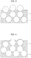
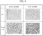
- the aperture ratio of a porous polyimide resin film can be increased by removing at least a part of a polyimide resin portion prior to formation of pores or of the porous polyimide resin film subsequent to formation of pores.
- a first aspect of the present invention relates to a method for producing a porous polyimide resin film comprising removing fine particles from a polyimide resin-fine particles composite film to thereby obtain a porous polyimide resin film, according to claim 1 in which the method comprises either removing at least a part of a polyimide resin portion of the polyimide resin-fine particle composite film prior to removing the fine particles, or removing at least a part of the porous polyimide resin film subsequent to removing the fine particles.
- a second aspect of the present disclosure relates to a porous polyimide resin film produced by the method according to the first aspect of the present invention.
- a third aspect of the present disclosure relates to a separator composed of the porous polyimide resin film according to the second aspect of the present invention.
- a fourth aspect of the present disclosure relates to a secondary battery comprising an electrolytic solution and the separator according to the third aspect of the present invention being disposed between a negative electrode and a positive electrode.
- a porous polyimide resin film having a high aperture ratio can be produced.
- the method for producing a polyimide resin film comprises either removing at least a part of a polyimide resin portion of the polyimide resin-fine particle composite film prior to removing the fine particles, or removing at least a part of the porous polyimide resin film subsequent to removing the fine particles.
- polyimide resin As a polyimide resin mentioned in the present Specification, polyimide or polyamide imide can be exemplified.
- Varnish can be produced by mixing a polyamide acid or polyimide with an organic solvent in which fine particles are dispersed in advance at an appropriate ratio, or by polymerizing a tetracarboxylic dianhydride and a diamine into a polyamide acid in an organic solvent in which fine particles are dispersed in advance, or by further performing imidization into a polyimide.
- the final viscosity thereof is preferably adjusted to 300 to 1500 cP and more preferably in a range of 400 to 700 cP.
- the varnish having a viscosity within this range can be formed into a uniform film.
- Resin fine particles and polyamide acid or polyimide or polyamide imide can be blended into the above described varnish such that a ratio of fine particles/polyimide resin is 1 to 3.5 (mass ratio) when a polyimide resin-fine particle composite film is obtained by calcination (if calcination is optional, drying), and the ratio of fine particles/polyimide resin is preferably 1.2 to 3 (mass ratio).
- the fine particles and the polyamide acid or polyimide or polyamide imide may be blended so as to provide the polyimide resin-fine particle composite film having a volume ratio of the fine particles/polyimide of 1.5 to 4.5.
- the ratio of fine particles/polyimide resin of 1.8 to 3 (volume ratio) is more preferable.
- a film can have pores at an appropriate density as a separator; if the mass ratio or volume ratio is not higher than the upper limit, a film can be stably formed without causing problems such as an increase in viscosity or cracking in the film. It should be noted that values for percent by volume and volume ratios are values at 25°C.
- Material for the fine particles used in the present invention is not particularly limited, and can be any material that is insoluble in the organic solvent to be used in the varnishes and can be selectively removed after film formation.
- the inorganic material include metal oxides such as silica (silicon dioxide), titanium oxide, and alumina (Al 2 O 3 );
- the organic materials include high-molecular-weight olefins (such as polypropylene and polyethylene) and organic polymer fine particles (resin fine particles) such as polystyrenes, acrylic resins (methyl methacrylate, isobutyl methacrylate, polymethyl methacrylate (PMMA)), epoxy resins, celluloses, polyvinyl alcohols, polyvinyl butyrals, polyesters, and polyethers.
- silica such as colloidal silica
- Resin fine particles used in the present invention can be selected from general linear polymers and known depolymerizable polymers, according to purpose without particular limitation.
- the linear polymer usually has a molecular chain that is randomly cleaved during thermal decomposition; and the depolymerizable polymer is decomposed into monomers during thermal decomposition. Both of them can be removed from the polyimide resin film by decomposing into monomers, a low molecular weight substance, or to CO 2 during heating.
- the resin fine particles to be used preferably have a decomposition temperature of 200°C to 320°C and more preferably 230°C to 260°C.
- a decomposition temperature of 200°C or higher allows formation of a film even if the varnish contains a high boiling point solvent, and broadens the selection of calcination conditions of the polyimide resin.
- a decomposition temperature of no higher than 320°C allows the resin fine particles to disappear without thermally damaging the polyimide resin.
- homopolymers of methyl methacrylate or isobutyl methacrylate (polymethyl methacrylate or polyisobutyl methacrylate) having low thermal decomposition temperature, or copolymers composed mainly of this are preferred from the viewpoint of handleability during pore formation.
- the fine particles to be used in the present invention preferably have a high sphericity and a low particle diameter distribution index. Fine particles satisfying these requirements show excellent dispersibility in the varnish and can be used without causing aggregation with one another. As the fine particles, those having a particle diameter (average diameter) of 100 to 2000 nm are used. The fine particles satisfying these requirements are preferable for providing pores having uniform pore diameters in the porous film obtained by removing the fine particles and, especially when the film is used as a separator, homogenizing an electric field being applied.
- fine particles (B1) in the first varnish and fine particles (B2) in the second varnish may be either the same or different.
- the fine particles (B1) preferably have a particle diameter distribution index lower than or equal to that of the fine particles (B2).
- the fine particles (B1) preferably have a sphericity lower than or equal to that of the fine particles (B2).
- the particle diameter (average diameter) of the fine particles (B1) is preferably smaller than that of the fine particles (B2).
- the fine particles (B1) preferably have a particle diameter of 100 to 1000 nm (more preferably 100 to 600 nm), and the fine particles (B2) preferably have a particle diameter of 500 to 2000 nm (more preferably 700 to 2000 nm).
- the use of the fine particles (B1) having a particle diameter smaller than that of the fine particles (B2) can give pores at a high aperture proportion with a small variation in the aperture proportion on the surface of the porous polyimide resin film being obtained, and can increase the strength of the film compared to the case of using fine particles having the same particle diameter as that of the fine particles (B1) in the entire porous polyimide resin film.
- the varnish may further contain a dispersant in addition to the fine particles, in order to uniformly disperse the fine particles in the varnish.
- the addition of the dispersant allows further uniform mixing of the polyamide acid, polyimide, or polyamide imide with the fine particles and further uniform dispersion of the fine particles in the molded or formed precursor film.
- dense apertures are provided on the surface of the finally formed porous polyimide resin, and the front and rear surfaces can be efficiently interconnected with each other to improve the air permeability of the film.
- the dispersant used in the present invention is not particularly limited and may be any known one.
- the dispersant include, but are not limited to, anionic surfactants such as salts of coconut fatty acid, salts of sulfonated castor oil, lauryl sulfate, polyoxyalkylene allylphenyl ether sulfate, alkylbenzenesulfonic acid, alkylbenzene sulfonate, alkyldiphenyl ether disulfonate, alkylnaphthalene sulfonate, dialkyl sulfosuccinate, isopropyl phosphate, polyoxyethylene alkyl ether phosphate, and polyoxyethylene allylphenyl ether phosphate; cationic surfactants such as oleylamine acetate, lauryl pyridinium chloride, cetyl pyridinium chloride, lauryl trimethylammonium chloride, stearyl trimethylammonium chlor
- the polyamide acid used in the present invention one obtained by polymerizing any tetracarboxylic dianhydride and diamine can be used without particular limitation.
- the amounts of the tetracarboxylic dianhydride and the diamine are not particularly limited, and the amount of the diamine is preferably 0.50 to 1.50 mol, more preferably 0.60 to 1.30 mol, and most preferably 0.70 to 1.20 mol, based on 1 mol of the tetracarboxylic dianhydride.
- the tetracarboxylic dianhydride can be appropriately selected from tetracarboxylic dianhydrides that have been conventionally used as raw materials for synthesizing polyamide acids.
- the tetracarboxylic dianhydride may be an aromatic tetracarboxylic dianhydride or an aliphatic tetracarboxylic dianhydride, but from the viewpoint of the heat resistance of the resulting polyimide resin, an aromatic tetracarboxylic dianhydride is preferably used.
- the tetracarboxylic dianhydrides may be used in a combination of two or more thereof.
- aromatic tetracarboxylic dianhydride examples include pyromellitic dianhydride, 1,1-bis(2,3-dicarboxyphenyl)ethane dianhydride, bis(2,3-dicarboxyphenyl)methane dianhydride, bis(3,4-dicarboxyphenyl)methane dianhydride, 3,3',4,4'-biphenyltetracarboxylic dianhydride, 2,3,3',4'-biphenyltetracarboxylic dianhydride, 2,2,6,6-biphenyltetracarboxylic dianhydride, 2,2-bis(3,4-dicarboxyphenyl)propane dianhydride, 2,2-bis(2,3-dicarboxyphenyl)propane dianhydride, 2,2-bis(3,4-dicarboxyphenyl)-1,1,1,3,3,3-hexafluoropropane dianhydride, 2,2-bis(
- Examples of the aliphatic tetracarboxylic dianhydride include ethylenetetracarboxylic dianhydride, butanetetracarboxylic dianhydride, cyclopentanetetracarboxylic dianhydride, cyclohexanetetracarboxylic dianhydride, 1,2,4,5-cyclohexanetetracarboxylic dianhydride, and 1,2,3,4-cyclohexanetetracarboxylic dianhydride.
- 3,3',4,4'-biphenyl tetra carboxylic dianhydride is preferable from the viewpoint of price, availability.
- These tetracarboxylic dianhydrides may be used alone or as a mixture of two or more thereof.
- the diamine can be appropriately selected from diamines that have been conventionally used as raw materials for synthesizing polyamide acids.
- the diamine can be either an aromatic diamine or an aliphatic diamine; however, an aromatic diamine is preferable from the viewpoint of heat resistance of the resulting polyimide resin.
- These diamines may be used in a combination of two or more thereof.
- aromatic diamine examples include diamino compounds having one phenyl group or about two to ten phenyl groups.
- examples of the aromatic diamine include phenylenediamines and their derivatives, diaminobiphenyl compounds and their derivatives, diaminodiphenyl compounds and their derivatives, diaminotriphenyl compounds and their derivatives, diaminonaphthalenes and their derivatives, aminophenylaminoindanes and their derivatives, diaminotetraphenyl compounds and their derivatives, diaminohexaphenyl compounds and their derivatives, and cardo-type fluorenediamine derivatives.
- the phenylenediamines are, for example, m-phenylenediamine and p-phenylenediamine.
- the phenylenediamine derivatives are diamines to which alkyl groups, such as a methyl group or an ethyl group, are bound, such as 2,4-diaminotoluene and 2,4-triphenylenediamine.
- the diaminodiphenyl compounds are obtained by linkage of two aminophenyl groups at their phenyl groups.
- the diaminodiphenyl compounds are 4,4'-diaminobiphenyl and 4,4'-diamino-2,2'-bis(trifluoromethyl)biphenyl.
- the diaminodiphenyl compounds are obtained by linkage of two aminophenyl groups at their phenyl groups via another group.
- the linkage is, for example, an ether linkage, a sulfonyl linkage, a thioether linkage, a linkage of an alkylene or its derivative group, an imino linkage, an azo linkage, a phosphine oxide linkage, an amide linkage, or an ureylene linkage.
- the alkylene linkage is a linkage of an alkylene having about 1 to 6 carbon atoms, and its derivative group is an alkylene group whose one or more hydrogen atoms have been replaced by, for example, halogen atoms.
- diaminodiphenyl compounds examples include 3,3'-diaminodiphenyl ether, 3,4'-diaminodiphenyl ether, 4,4'-diaminodiphenyl ether, 3,3'-diaminodiphenyl sulfone, 3,4'-diaminodiphenyl sulfone, 4,4'-diaminodiphenyl sulfone, 3,3'-diaminodiphenyl methane, 3,4'-diaminodiphenyl methane, 4,4'-diaminodiphenyl methane, 4,4'-diaminodiphenyl sulfide, 3,3'-diaminodiphenyl ketone, 3,4'-diaminodiphenyl ketone, 2,2-bis(p-aminophenyl)propane, 2,2'-bis(p-aminophenyl)he
- p-phenylenediamine, m-phenylenediamine, 2,4-diamino toluene, and 4,4'-diamino diphenyl ether are preferable from the viewpoint of price, availability.
- the diaminotriphenyl compound is formed by linkage of two aminophenyl groups and one phenylene group, all of which are linked to each other through another group, the another group being selected from the same groups as in the diaminodiphenyl compounds.
- Examples of the diaminotriphenyl compounds include 1,3-bis(m-aminophenoxy)benzene, 1,3-bis(p-aminophenoxy)benzene, and 1,4-bis(p-aminophenoxy)benzene.
- diaminonaphthalenes examples include 1,5-diaminonaphthalene and 2,6-diaminonaphthalene.
- aminophenylaminoindanes examples include 5- or 6-amino-1-(p-aminophenyl)-1,3,3-trimethylindane.
- diaminotetraphenyl compounds examples include 4,4'-bis(p-aminophenoxy)biphenyl, 2,2'-bis[p-(p'-aminophenoxy)phenyl]propane, 2,2'-bis[p-(p'-aminophenoxy)biphenyl]propane, and 2,2'-bis[p-(m-aminophenoxy)phenyl]benzophenone.
- the aliphatic diamine has, for example, about 2 to 15 carbon atoms, and specifically, examples thereof include pentamethylenediamine, hexamethylenediamine, and heptamethylenediamine.
- the aliphatic diamine may be a compound having at least one substituent selected from the group consisting of halogen atoms and methyl, methoxy, cyano, and phenyl groups for hydrogen atoms of the diamine.
- the polyamide acid to be used in the present invention may be produced by any method without particular limitation, and can be produced by a known method, for example by reaction of an acid with a diamine component in organic solvent.
- the reaction of a tetracarboxylic dianhydride and a diamine is usually performed in an organic solvent.
- the organic solvent to be used for the reaction of a tetracarboxylic dianhydride and a diamine may be any organic solvent that can dissolve the tetracarboxylic dianhydride and the diamine without reacting with the tetracarboxylic dianhydride and the diamine.
- the organic solvent may be a single solvent or a mixture of two or more solvents.
- Examples of the organic solvent used for reaction of tetracarboxylic dianhydride with diamine include: nitrogen-containing polar solvents such as N-methyl-2-pyrrolidone, N,N-dimethylacetamide, N,N-diethylacetamide, N,N-dimethylformamide, N,N-diethylformamide, N-methylcaprolactam, and N,N,N',N'-tetramethylurea; lactone-based polar solvents such as ⁇ -propiolactone, ⁇ -butyrolactone, ⁇ -valerolactone, ⁇ -valerolactone, ⁇ -caprolactone and ⁇ -caprolactone; dimethylsulfoxide; acetonitrile; fatty acid esters such as ethyl lactate and butyl lactate; ethers such as diethyleneglycol dimethylether, diethyleneglycol diethylether, dioxane, tetrahydrofuran, methyl cell
- organic solvents may be used alone or as a mixture of two or more thereof. Among these, a combination of the nitrogen-containing polar solvent with the lactone-based polar solvent is preferable.
- the amount of the organic solvent is not particularly limited but is desirably such an amount that the content of the resulting polyamide acid is 5% to 50% by mass.
- organic solvents from the viewpoint of the solubility of the resulting polyamide acid, preferred are nitrogen-containing polar solvents, such as N-methyl-2-pyrrolidone, N,N-dimethylacetamide, N,N-diethylacetamide, N,N-dimethylformamide, N,N-diethylformamide, N-methylcaprolactam, and N,N,N',N'-tetramethylurea.
- the organic solvent can be a blended solvent comprising lactone-based polar solvent such as ⁇ -butyrolactone, which is preferably 1 to 20% by mass and more preferably 5 to 15% by mass with respect to the entire amount of organic solvent.
- the polymerization temperature is usually -10°C to 120°C and preferably 5°C to 30°C.
- the polymerization time varies depending on the raw material composition and is usually 3 to 24 hours (hr).
- the polyamide acid solution prepared under such conditions preferably has an intrinsic viscosity of 1000 to 100000 centipoises (cP), more preferably in a range of 5000 to 70000 cP.
- the polyimide used in the present invention can be any known polyimide, without restriction by its structure and molecular weight, as long as the polyimide is soluble in the organic solvent to be used in the varnish according to the present invention.
- the side chain of the polyimide may have a condensable functional group, such as a carboxy group, or a functional group enhancing the cross-linking reaction during calcination.
- a monomer for introducing a flexible bend structure into the main chain for example, to use an aliphatic diamine, such as ethylenediamine, hexamethylenediamine, 1,4-diaminocyclohexane, 1,3-diaminocyclohexane, or 4,4'-diaminodicyclohexylmethane; an aromatic diamine, such as 2-methyl-1,4-phenylenediamine, o-tolidine, m-tolidine, 3,3'-dimethoxybenzidine, or 4,4'-diaminobenzanilide; a polyoxyalkylenediamine, such as polyoxyethylenediamine, polyoxypropylenediamine, or polyoxybutyrenediamine; a polysiloxanediamine; 2,3,3',4'-oxydiphthalic anhydride, 3,4,3',4'-oxydiphthal
- a monomer containing a functional group for improving the solubility in an organic solvent for example, to use a fluorinated diamine, such as 2,2'-bis(trifluoromethyl)-4,4'-diaminobiphenyl or 2-trifluoromethyl-1,4-phenylenediamine.
- a monomer that is mentioned in the paragraph describing the polyamide acid may be used within a range that does not inhibit the solubility.
- the polyimide soluble in an organic solvent to be used in the present invention may be produced by any method and, for example, can be produced by a known method of, for example, chemically imidizing or thermally imidizing a polyamide acid and dissolving the imidized polyamide in an organic solvent.
- Examples of such polyimides include aliphatic polyimide (full-aliphatic polyimides) and aromatic polyimides, and aromatic polyimides are preferred.
- the aromatic polyimide may be one prepared by a thermal or chemical ring-closing reaction of a polyamide acid having repeating units represented by Formula (1) or one prepared by dissolving a polyimide having repeating units represented by Formula (2) in a solvent.
- Ar represents an aryl group.
- the polyamide imide used in the present invention can be any known polyamide imide, without restriction by its structure and molecular weight, as long as the polyamide imide is soluble in the organic solvent to be used in the varnish according to the present invention.
- the side chain of the polyamide imide may have a condensable functional group, such as a carboxy group, or a functional group enhancing a cross-linking reaction during calcination.
- polyamide imide used in the present invention polyamide imide obtained by reacting any trimellitic anhydride with diisocyanate, and polyamide imide obtained by imidizing a precursor polymer obtained as a result of reaction of a reactive derivative of any trimellitic anhydride with diamine can be used without particular limitation.
- trimellitic anhydride for example: trimellitic anhydride; trimellitic anhydride halides such as trimellitic anhydride chloride; trimellitic anhydride esters; can be exemplified.
- any diisocyanate for example, meta-phenylene diisocyanate, p-phenylene diisocyanate, o-tolidine diisocyanate, p-phenylene diisocyanate, m-phenylene diisocyanate, 4,4'-oxybis (phenyl isocyanate), 4,4'-diphenylmethane diisocyanate, bis[4-(4-isocyanate phenoxy) phenyl] sulfone, 2,2'-bis[4-(4-isocyanate phenoxy) phenyl] propane, 2,4-tolylene diisocyanate, 2,6-tolylene diisocyanate, 4,4'-diphenylmethane diisocyanate, 3,3'-dimethyldiphenyl-4,4'-diisocyanate, 3,3'-diethyldiphenyl-4,4'-diisocyanate, isophorone diisocyanate,
- the organic solvent used in the varnish is not particularly limited as long as the solvent can dissolve a resin composed of polyamide acid and/or polyimide while not dissolving the fine particles; and can include those exemplified as the solvent used for reaction of tetracarboxylic dianhydride with diamine.
- the solvent can be used alone or in a combination of two or more types.
- the content of the blended solvent (S) in all components of the varnish is preferably 50 to 95% by mass, and more preferably 60 to 85% by mass.
- the solid content concentration of the varnish is preferably 5 to 50% by mass, and more preferably 15 to 40% by mass.
- a volume ratio of polyamide acid, polyimide or polyamide imide (A1) to the fine particles (B1) in the first varnish is preferably 19:81 to 45:65. If the volume of the fine particles is at least 65 with respect to the total volume of the varnish being 100, the particles are uniformly dispersed; and if the volume is 81 or less, the particles are dispersed without causing aggregation with one another, allowing uniform formation of pores on the surface of the polyimide resin film on the substrate side.
- a volume ratio of polyamide acid, polyimide or polyamide imide (A2) to the fine particles (B2) in the second varnish is preferably 20:80 to 50:50. If the volume of the fine particles is at least 50 with respect to the total volume being 100, the particles themselves are uniformly dispersed; and if the volume is 80 or less, the particles are not aggregated and no cracking is caused on the surface, resulting in stable formation of a porous polyimide resin film having superior electrical characteristics.
- the second varnish is lower in the fine particle content than the first varnish; by satisfying this condition, even if the polyamide acid, polyimide or polyamide imide contains a large amount of fine particles, the strength and flexibility of the uncalcined composite film, the polyimide resin-fine particle composite film, and the porous polyimide resin film can be secured.
- the lower content ratio of the fine particles in the layer can reduce the cost of producing the film.
- known components such as an antistatic agent, a fire retardant, a chemical imidizing agent, a condensation agent, a release agent, a superficial regulator, can be added as necessary for static prevention, fire resistance, releasability, applicability.
- the uncalcined composite film containing polyamide acid or polyimide resin as well as the fine particles is formed by: applying the above described varnish onto a substrate; and drying under ordinary pressure or under vacuum at 50 to 100°C (preferably at 0 to 50°C), more preferably under ordinary pressure at 60 to 95°C (further preferably at 65 to 90°C).
- a releasing layer can also be provided on the substrate.
- the releasing layer can be provided by applying a releasing agent onto the substrate and drying or baking.
- the releasing agent used here may be a known releasing agent, such as an alkylphosphate ammonium salt-based or fluorine-based agent or silicon, without particular restriction.
- a slight amount of the releasing agent remains on the peeled surface of the uncalcined composite film. The releasing agent thus remaining would have substantial adverse effects on wettability and electrical characteristics of the film surface, and is therefore preferably removed.
- the uncalcined composite film peeled from the substrate is preferably washed with an organic solvent and the like.
- the washing method can be selected from known methods, such as a method in which the film is immersed in a washing solution and is then taken out, a method of shower washing.
- known methods such as air drying at ambient temperature, heating in a thermostatic bath up to an appropriate temperature can be applied without limitation to the uncalcined composite film thus washed.
- a method of fixing ends of the uncalcined composite film to a frame or the like made of stainless steel to thereby prevent deformation can be employed.
- the steps of forming the releasing layer and washing the uncalcined composite film can be omitted.
- a first uncalcined composite film of 1 to 5 ⁇ m in thickness is formed by: applying the above described first varnish onto a substrate as is; and drying under ordinary pressure or under vacuum at 0 to 100°C (preferably at 0 to 90°C), more preferably under ordinary pressure at 10 to 100°C (further preferably at 10 to 90°C).
- a second uncalcined composite film of 5 to 30 ⁇ m in thickness is formed by: applying the above described second varnish onto the first uncalcined composite film thus formed; and drying similarly at 0 to 80°C (preferably at 0 to 50°C), more preferably under ordinary pressure at 10 to 80°C (further preferably at 10 to 30°C) to thereby obtain the two-layered uncalcined composite film.
- the calcination temperature varies depending on the structure of polyamide acid or polyimide resin contained in the uncalcined composite film and the presence or absence of a condensing agent, and is preferably 120°C to 375°C and more preferably 150°C to 350°C.
- Calcination is not necessarily clearly separated from the drying step, and in a case of calcining at 375°C, for example, a method of increasing the temperature from room temperature to 375°C over 3 hours and then holding at 375°C for 20 minutes; or a stepwise drying-thermal imidization method of increasing the temperature stepwise by 50°C from room temperature to 375°C (holding the temperature of each step for 20 minutes) and finally holding at 375°C for 20 minutes.
- a method of fixing ends of the uncalcined composite film to a frame or the like made of stainless steel to thereby prevent deformation can be employed.
- the thickness of the resulting polyimide resin-fine particle composite film can be determined by, for example, measuring the thicknesses of a plurality of positions by a micrometer or the like and averaging the thicknesses.
- Preferred average film thickness varies depending on the purpose of the polyimide resin-fine particle composite film or the porous polyimide resin film, however, film thickness can be at least 1 ⁇ m, preferably 5 to 500 ⁇ m, and more preferably 10 to 100 ⁇ m, in the use as a separator for example.
- the porous polyimide resin film can be produced with high reproducibility by selecting an appropriate method for removing the fine particles from the polyimide resin-fine particle composite film.
- the polyimide-fine particle composite film can be made porous by dissolving and removing the silica with a low-concentration hydrogen fluoride solution (HF).
- HF low-concentration hydrogen fluoride solution
- the resin fine particles can be decomposed and removed by heating at a temperature equal to or greater than the above specified thermal decomposition temperature of the resin fine particles and lower than the thermal decomposition temperature of the polyimide resin.
- the method for producing a polyimide resin film of the present invention comprises a polyimide resin removing step of either removing at least a part of a polyimide resin portion of the polyimide resin-fine particle composite film prior to the fine particle removing step, or removing at least a part of the porous polyimide resin film subsequent to the fine particle removing step.
- a polyimide resin removing step of removing at least a part of a polyimide resin portion of the polyimide resin-fine particle composite film prior to the fine particle removing step is described.
- FIG. 1 is a diagram schematically illustrating a polyimide resin-fine particle composite film. Fine particles 1 are dispersed in a polyimide resin portion 2 to thereby form the polyimide resin-fine particle composite film. In the vicinity of a surface of the polyimide resin-fine particle composite film, the polyimide resin portion 2 covers a part of or entire fine particles 1. It should be noted that, since FIG. 1 is a schematic diagram, the fine particles 1 are illustrated in substantially the same diameter; however, the present invention is not limited thereto and the particle diameters of the fine particles 1 can have a distribution.
- removing at least a part of a polyimide resin portion prior to the fine particles removing step means removing any part of the polyimide resin portion 2 in FIG. 1 .
- FIG. 2 illustrates a case in which a relatively small amount of polyimide resin portion is removed; and
- FIG. 3 illustrates a case in which a larger amount of polyimide resin portion is removed.
- the fine particles can also be partially removed.
- the aperture ratio of the porous polyimide resin film as a final product can be increased, compared to a case of not removing the polyimide resin portion.
- FIG. 4 is a diagram schematically illustrating the porous polyimide resin film immediately after the fine particle removing step. Pores 3 formed by disappearance of the fine particles are distributed in the porous polyimide resin film 4. Similarly to FIG. 1 , since FIG. 4 is a schematic diagram, the pores 3 are illustrated in substantially the same diameter; however, the present invention is not limited thereto and the diameters of the pores 3 can have a distribution.
- Removing at least a part of the porous polyimide resin film subsequent to the fine particles removing step means removing any part of the porous polyimide resin film 4 in FIG. 4 .
- FIG. 5 illustrates a case in which a relatively small amount of porous polyimide resin film is removed
- FIG. 6 illustrates a case in which a larger amount of porous polyimide resin film is removed.
- the pores can be made so as to interconnect with each other, by removing the porous polyimide resin film between adjacent pores.
- the aperture ratio of the porous polyimide resin film as a final product can be increased, compared to a case of not removing.
- the above mentioned step of removing at least a part of the polyimide resin portion, or the step of removing at least a part of the porous polyimide resin film can be performed by a normal chemical etching method, physical removal method, or a combination thereof.
- a treatment with chemical etching solution such as inorganic alkali solution or organic alkali solution can be exemplified.
- the inorganic alkali solution is preferable.
- the inorganic alkali solution hydrazine solution containing hydrazine hydrate and ethylenediamine; solution of alkali metal hydroxides such as potassium hydroxide, sodium hydroxide, sodium carbonate, sodium silicate, sodium metasilicate; ammonia solution; etching solution composed primarily of hydroxylation alkali, hydrazine and 1,3-dimethyl-2-imidazolidinone can be exemplified.
- organic alkali solution primary amines such as ethylamine and n-propylamine; secondary amines such as diethylamine and di-n-butylamine; tertiary amines such as triethylamine and methyldiethylamine; alcohol amines such as dimethylethanolamine and triethanolamine; quaternary ammonium salts such as tetramethylammonium hydroxide and tetraethylammonium hydroxide; and alkaline solution of cyclic amines such as pyrrol and piperidine, can be exemplified.
- primary amines such as ethylamine and n-propylamine
- secondary amines such as diethylamine and di-n-butylamine
- tertiary amines such as triethylamine and methyldiethylamine
- alcohol amines such as dimethylethanolamine and triethanolamine
- quaternary ammonium salts such as
- Pure water and alcohols can be selected as appropriate as a solvent for the above mentioned solutions.
- a solution with an appropriate amount of surfactant can also be used.
- Alkali concentration is for example 0.01 to 20% by mass.
- etching by plasma oxygen, argon
- corona discharge a method of dispersing abrasives (e.g., alumina (hardness 9)) in liquid and spraying onto a surface of the polyimide resin-fine particle composite film or the porous polyimide resin film at a rate of 30 to 100 m/s to treat the surface of the polyimide resin-fine particle composite film or the porous polyimide resin film
- abrasives e.g., alumina (hardness 9)
- the above described method is applicable to either of the polyimide resin removing steps prior to and subsequent to the fine particle removing step, and is therefore preferable. It should be noted that, in a case of performing chemical etching after the fine particle removing step, the aperture ratio can be increased by increasing the size of interconnected pores (pores that are formed where the fine particles were adjacent) in the porous polyimide resin film.
- a method of: pressure bonding a target surface onto a mount film (for example, a polyester film such as a PET film) being wetted with liquid; drying or not drying; and then peeling the porous polyimide resin film from the mount film can also be employed. Due to liquid surface tension or electrostatic adhesive force, a porous polyimide resin film is torn off from a mount film under conditions in which only the face of the porous polyimide resin film was left on the mount film. In this method, the configuration of the porous polyimide resin film is as illustrated by the schematic diagram of FIG. 5 .
- the porous polyimide resin film produced by the above described production method according to the present invention is preferable for having a further increased aperture ratio, and, if employed as a separator in a lithium-ion battery for example, allowing downsizing of the inside of the battery.
- the aperture ratio of the porous polyimide resin film can be evaluated by obtaining Gurley permeability for a thickness of 25 ⁇ m, in other words the number of seconds required for 100 ml air permeating the film, according to JISP8117.
- the porous polyimide resin film of the present invention can be used as the separator for a secondary battery, such as a nickel cadmium battery, a nickel hydrogen battery, a lithium ion secondary battery, and a lithium metal secondary battery and is particularly preferably used as the porous separator for a lithium ion secondary battery.
- a secondary battery such as a nickel cadmium battery, a nickel hydrogen battery, a lithium ion secondary battery, and a lithium metal secondary battery and is particularly preferably used as the porous separator for a lithium ion secondary battery.
- the porous polyimide resin film produced by the production method of the present invention can also be used as the separator of a secondary battery, a fuel cell electrolyte film, a film for separating a gas or liquid, or a low dielectric constant material.
- a secondary battery according to the fourth aspect of the present invention is characterized in comprising an electrolytic solution and the separator according to the third aspect being disposed between a negative electrode and a positive electrode.
- the secondary battery of the present invention may be of any type and may have any configuration.
- the present invention can be employed with no particular limitation in known secondary batteries such as nickel cadmium and nickel hydrogen batteries as well as a lithium ion secondary battery, as long as the battery has a configuration in which a battery element including a positive electrode, a separator, and a negative electrode being laminated in this order so as to satisfy the above-described requirements is impregnated with an electrolytic solution and encapsulated in an outer package.
- the negative electrode of the secondary battery of the present invention can have a structure in which a negative electrode mixture composed of a negative electrode active material, a conductive auxiliary agent, and a binder is formed on a collector.
- a negative electrode active material cadmium hydroxide can be used in nickel cadmium batteries, and a hydrogen-occlusion alloy can be used in nickel hydrogen batteries.
- a material that can be electrochemically doped with lithium can be employed. Examples of such active materials include carbon materials, silicon, aluminum, tin, and Wood's metal.
- Examples of the conductive auxiliary agent constituting the negative electrode include carbon materials such as acetylene black and Ketjen black.
- the binder is composed of an organic polymer, and examples thereof include polyvinylidene fluoride and carboxymethyl cellulose.
- the collector can be, for example, copper foil, stainless steel foil, or nickel foil.
- the positive electrode can have a structure in which a positive electrode mixture composed of a positive electrode active material, a conductive auxiliary agent, and a binder is formed on a collector.
- the positive electrode active material can be nickel hydroxide in nickel cadmium batteries and can be nickel hydroxide or nickel oxyhydroxide in nickel hydrogen batteries.
- examples of the positive electrode active material include lithium-containing transition metal oxides, specifically, LiCoO 2 , LiNiO 2 , LiMn 0.5 Ni 0.5 O 2 , LiCo 1/3 Ni 1/3 Mn 1/3 O 2 , LiMn 2 O 4 , LiFePO 4 , LiCo 0.5 Ni 0.5 O 2 , and LiAl 0.25 Ni 0.75 O 2 .
- Examples of the conductive auxiliary agent include carbon materials such as acetylene black and Ketjen black.
- the binder is an organic polymer, and examples thereof include polyvinylidene fluoride.
- the collector can be, for example, aluminum foil, stainless steel foil, or titanium foil.
- the electrolytic solution in, for example, a nickel cadmium battery or a nickel hydrogen battery is a potassium hydroxide solution.
- the electrolytic solution in a lithium ion secondary battery is composed by dissolving a lithium salt in a non-aqueous solvent.
- the lithium salt include LiPF 6 , LiBF 4 and LiClO 4 .
- the non-aqueous solvent include propylene carbonate, ethylene carbonate, dimethyl carbonate, diethyl carbonate, ethyl methyl carbonate, g-butyrolactone, and vinylene carbonate. These solvents may be used alone or as a mixture.
- Examples of the outer package material include metal cans and aluminum laminate packs.
- the shape of the battery is, for example, a rectangular shape, a cylindrical shape, or a coin shape; however, the separator of the present invention can be suitably applied to any shape.
- Polyamide acid solution was obtained by blending 13.25 g of the polyamide acid and 30 g of the organic solvent (1). 75 g of silica (2) as the fine particles was added to the polyamide acid solution thus obtained to prepare a first varnish. It should be noted that a volume ratio of the polyamide acid and the silica (2) in the first varnish was 22:78 (a mass ratio is 15:85).
- Polyamide acid solution was obtained by blending 13.25 g of the polyamide acid and 30 g of the organic solvent (1). 53 g of silica (1) as the fine particles was added to the polyamide acid solution thus obtained to prepare a second varnish. It should be noted that a volume ratio of the polyamide acid and the silica (1) in the second varnish was 28:72 (a mass ratio is 20:80).
- a film of the second varnish was formed on a glass plate with an applicator.
- An uncalcined composite film having a thickness of 25 ⁇ m was produced by pre-baking at 70°C for 5 minutes.
- the uncalcined composite film was peeled from the substrate and dried to obtain an uncalcined composite film (1).
- the uncalcined composite film (1) was heated (post-baking) at 320°C for about 15 minutes, to complete imidization and obtain a polyimide-fine particle composite film (1).
- the polyimide-fine particle composite film (1) thus obtained was immersed in 10% HF solution for 10 minutes to remove the fine particles contained in the film, washed with water and dried, to obtain a porous polyimide film (1).
- a film of the first varnish was formed on a glass plate with an applicator, and then baked at 70°C for 1 minute, to obtain a first uncalcined composite film of about 2 ⁇ m in thickness. Subsequently, a second uncalcined composite film was formed using the second varnish on the first uncalcined composite film and pre-baked at 70°C for 5 minutes, to obtain a two-layered uncalcined composite film (2) of about 25 ⁇ m in total thickness.
- the uncalcined composite film (2) was heated (post-baking) at 320°C for about 15 minutes, to complete imidization and obtain a polyimide-fine particle composite film (2).
- the polyimide-fine particle composite film (2) thus obtained was immersed in 10% HF solution for 10 minutes to remove the fine particles contained in the film, washed with water and dried, to obtain a porous polyimide film (2).
- the porous polyimide film (2) thus obtained was subjected to a comparison between different chemical etching conditions, using an aqueous solution of tetraalkylammonium hydroxide (TMAH) or NaOH solution, according to Table 1 below.
- TMAH tetraalkylammonium hydroxide
- NaOH NaOH
- TMAH TMAH
- NaOH 50% by mass aqueous solution of methanol
- porous polyimide films (1) and (2) obtained above were subjected to chemical etching according to Table 1 below, employing the NaOH containing etching solution, which had exhibited, among the results of Examples 1 to 8, superior form change of pores on the surface upon removal of a part of the porous polyimide film; and then samples of 25 ⁇ m in thickness were cut therefrom in 5 cm squares.
- the time for 100 mL of air passing through the sample was measured with a Gurley densometer (manufactured by Toyo Seiki Co., Ltd.) in accordance with JIS P 8117. Results are also shown in Table 1.
- FIG. 7 shows that a part of the porous polyimide film is removed and the pore shape on the surface changes as a result of chemical etching.
- the Gurley permeability of the porous polyimide film in Table 1 shows that the time required for 100 ml of air to pass therethrough was substantially reduced as the chemical etching proceeded, and communicability between a foreside and a backside of the porous polyimide film was improved. From a relationship between the permeation time and the thickness change, the improvement in the permeability by the chemical etching is thought to result not only from a reduction in thickness, but also mainly from an increase in aperture ratio.
- a porous polyimide film was prepared in a similar way to [Preparation of varnish] to [Formation of porous polyimide film] described with respect to the porous polyimide film (2).
- the porous polyimide film washed with water in a wet state was placed on a polyethylene terephthalate (PET) film and baked. Since a surface layer of the porous polyimide film was electrostatically adhered to the PET film, by subsequently peeling the porous polyimide film thus dried from the PET film, only the surface layer remained on the PET film.
- PET polyethylene terephthalate
- a face peeled from the PET film is the film formed by the first varnish (a negative electrode side when used as a separator for a lithium-ion battery).
- FIG. 8 shows the surface of the PET film before and after this treatment. The remaining segments of the porous polyimide film surface layer can be observed on the surface of the PET film after the treatment.
- tetracarboxylic dianhydride 6.5 g of tetracarboxylic dianhydride, 6.7 g of diamine, and 30 g of the organic solvent (1) were put into a separable flask equipped with a stirrer, a stirring blade, a reflux condenser, and a nitrogen gas inlet tube. Nitrogen was introduced into the flask through the nitrogen gas introduction tube and a nitrogen atmosphere was provided in the flask. Subsequently, the tetracarboxylic dianhydride and the diamine were reacted at 50°C for 20 hours by stirring the contents of the flask to prepare a polyamide acid solution.
- a second varnish in which a volume ratio is 28:72 (mass ratio is 20:80) was prepared in a similar way to [Preparation of varnish - 3], except that 53 g of silica (1) having an average particle diameter of 700 nm was added to the resulting polyamide acid solution.
- a film of the first varnish was formed on a glass plate with an applicator, and then baked at 70°C for 1 minute, to obtain a first uncalcined composite film of about 1 ⁇ m in thickness. Subsequently, a second uncalcined composite film was formed using the second varnish on the first uncalcined composite film and pre-baked at 70°C for 5 minutes, to obtain a two-layered uncalcined composite film (2) of about 20 ⁇ m in total thickness.
- the uncalcined composite film was peeled off from the substrate, the release agent was then removed with ethanol, and a heat treatment was performed at 320°C for 15 minutes to complete imidization and obtain a polyimide-fine particle composite film.
- the polyimide-fine particle composite film was immersed in a 10% HF solution for 10 minutes to remove the fine particles contained in the film.
- Alkaline etching solution was prepared by diluting 2.38% by mass of an aqueous solution of TMAH with 50% by mass of an aqueous solution of methanol, to 1.04%. A part of the polyimide surface was removed by immersing the porous polyimide film in this etching solution. Permeability of the porous polyimide film thus obtained was 63 seconds.
- a porous polyimide film was formed as in Example 14 except that the varnish was prepared by using a dispersant in an amount of 10 parts by weight based on 100 parts by weight of silica. Permeability of the porous polyimide film thus obtained was 60 seconds.
- Example 15 with the dispersant shows a shorter permeation time than Example 14 without the dispersant, and therefore improvement in interconnectivity between pores.
- the strength of the film did not deteriorate even after the chemical etching, and the film had good handleability.
- the separator was used such that a surface thereof with the layer which had been produced by using the first varnish faced the negative electrode.
- the batteries were used as Examples B1 and B2.
- the charge-discharge characteristics were evaluated by charging each coin battery for evaluation at a current density of 2.2 mAh (1C) up to 4.1 V (CC-CV operation) and then discharging the battery at a current density of 2.2 mAh (1C) or 3C down to 2.5 V (CC operation), in a thermostatic chamber.
- Table 3 shows the results.
- the values shown in parentheses are the electrostatic capacity retention ratios (%) at a rate of 3C when the capacity at 1C is defined as 100%.
- a nickel-cobalt-manganese ternary positive electrode and an artificial graphite negative electrode were used as the electrodes, and arranged such that the surface of the layer formed of the first varnish was in contact with the negative electrode.
- monolayer laminate cell batteries were prepared similarly to the above except that a commercially available polyethylene-based (PE-based) or cellulose-based separator was used. These batteries were used as Comparative Examples B1 and B2.
- the PE-based separator being used had an average pore diameter of 80 nm, a thickness of 20 ⁇ m, an air permeability of 270 seconds, and a porosity of 42%; and the cellulose-based separator being used had an average pore diameter of 3000 nm, a thickness of 25 ⁇ m, an air permeability of 135 seconds, and a porosity of 70%.
- the potential change by lithium occlusion was measured with a charge-discharge measuring apparatus.
- the battery was charged up to 4.2 V at a charging speed of 0.2C at 25°C, and after a pause of 10 minutes, was then discharged at a discharging speed of 2C down to a voltage range of 2.7 V. After the discharge, a pause of 10 minutes was taken.
- the battery was evaluated for the Ah utilization rate and Wh utilization rate (energy retention ratio) during this process. Results are shown in Table 3.
- the separator used in each battery was evaluated for the heat resistance using a soldering iron of about 250°C according to the following criteria:
- a crushing test was performed by charging a monolayer laminate cell battery at a voltage of 4.2 V and then compressing the battery in a resting state in the direction vertical to the length direction with a round bar having a diameter of 15.8 mm.
- the time when the voltage reduced was determined as the occurrence of internal short-circuit of the battery, and the battery was evaluated by the pressure at the time of the occurrence of the internal short-circuit.
- the amount of reduction in voltage 5 seconds after the time of the reduction of the voltage was defined as ⁇ V (V). A higher value of the pressure is preferred, and a lower reduction in voltage is preferred.
- Example B1 and Comparative Examples B1 and B2 the potential change due to lithium occlusion was measured by using a charge-discharge measuring apparatus.
- a charge-discharge measuring apparatus At a temperature of 0°C and a charging speed of 1C, an Ah efficiency and a capacity retention ratio at a fifth cycle (ratio to the electric discharge capacity at a first cycle) were obtained under conditions of: charging CCCV: 4.2 V; CV: 1 hour; discharge: 2.7 V. Results are shown in Table 4.
- the negative electrode was taken out from the battery after completion of the above described charge-discharge characteristics evaluation test, and a surface thereof was observed. Statuses of dendrite generation on the negative electrode surfaces are shown in Table 4.
- the negative electrode surfaces of Example B1, Comparative Example B1 and Comparative Example B2 were enlarged 500 times and observed with an optical microscope. The images are shown in FIGS. 9 to 11 .
- Example B1 employing the separator of the present invention was superior in heat resistance and performance in the crushing test to Comparative Examples B1 and B2 employing commercially available separators.
- FIGS. 9 to 11 are pictures of surfaces of negative electrodes taken out from batteries of Example B1 and Comparative Examples B1 and B2 after completion of the above described charge-discharge characteristics evaluation test.
- White bright spots due to generation of lithium dendrite were observed on each of these.
- the battery of Example B1 there are only a few bright spots on the negative electrode, showing that lithium dendrite generation due to charge and discharge is effectively suppressed.
- the bright spots on the negative electrodes taken out from Comparative Examples B1 and B2 are large in size and number. In other words, it can be observed that lithium dendrite generation occurs more frequently in Comparative Examples employing commercially available separators based on polyethylene (PE) or cellulose, compared to a case of using the separator of the present invention.
- PE polyethylene
- Table 4 and FIGS. 9 to 11 show that the battery employing the separator of Example of the present invention can suppress an amount of lithium dendrite generated on a negative electrode surface and provides a superior capacity retention ratio at low temperature, suggesting that an electrical field applied to the separator is homogenized.
- a film of the varnish (5) was formed on a PET film with an applicator.
- An uncalcined composite film having a thickness of approximately 28 ⁇ m was produced by pre-baking at 100°C for 5 minutes.
- the uncalcined composite film was peeled from the substrate and dried to obtain an uncalcined composite film (5), that is a polyamide imide-fine particle composite film (1).
- the solvent had been removed from the uncalcined composite film (5) (polyamide imide-fine particle composite film (1)), the solvent had been removed.
- the uncalcined composite film was not subjected to a calcining step.
- the polyamide imide-fine particle composite film (1) thus obtained was immersed in 10% HF solution for 10 minutes to remove the fine particles contained in the film, washed with water and dried, to obtain a porous polyamide imide film (1).
- porous polyamide imide film (1) thus obtained was subjected to a comparison between different chemical etching conditions, using NaOH solutions described below, according to Table 5 below.
- Table 5 shows that, similarly to the case of the porous polyimide film, even in a case of employing polyamide imide as the polyimide resin, the chemical etching improved Gurley permeability and communicability between a foreside and a backside of the porous polyamide imide film. From a relationship between the permeation time and the thickness change, the improvement in the permeability by the chemical etching is thought to result from not only a reduction in thickness, but also mainly from an increase in aperture ratio as a result of enlargement of openings on the surface and interconnected pores.
Description
- The present invention relates to a method for producing a porous polyimide resin film, a porous polyimide resin film, and a separator employing the film.
- In recent years, because of a reduction in the size of portable electronic devices and the development of hybrid automobiles, electric automobiles, etc. for addressing environmental problems such as an increase in atmospheric pollution and carbon dioxide, secondary batteries having excellent characteristics, such as high efficiency, high output, high energy density, and light weight are needed. As such secondary batteries, various secondary batteries are being researched and developed.
- A lithium battery, which is a kind of secondary battery, usually has a structure in which a space between a positive electrode (cathode) and a negative electrode (anode) is filled with a lithium salt, such as LiPF6, dissolved in an electrolytic solution, for example, a non-aqueous organic solvent. Lithium transition metal oxide is used as the positive electrode, and lithium or carbon (graphite) is mainly used as the negative electrode. The electrolytic solution has good ionic conductivity and negligible electrical conductivity. During charging, lithium ions move from the positive electrode to the negative electrode, and during discharging, lithium ions move in the reverse direction.
- The positive electrode and the negative electrode of the lithium battery are separated from each other with a separator of a porous polymer film and are formed into a structure preventing their direct electric contact. Accordingly, the separator for a secondary battery is required to have various characteristics, such as film thickness (thinness), mechanical strength, ionic conductance (during containing of an electrolytic solution), electric insulation, electrolytic solution resistance, electrolytic solution-retaining property, and wettability. As the separators for secondary batteries having these properties, microporous films made of polyolefins, such as polyethylene and polypropylene, are generally used. These microporous films have random pores at a porosity of about 35% to 40% and are widely used as separators for lithium secondary batteries having negative electrodes of carbon.
- However, these conventionally known separators are known to deposit lithium metal on graphite negative electrodes due to repeated charge and discharge cycles. Furthermore, the repetition of charge and discharge of a battery is known to cause the growth of dendrite lithium, resulting in a short circuit of the battery and this problem needs to be solved (Patent Document 1). Separately, it has been tried to use a polyimide having a high heat-resistance and high safety in the separator (
Patent Documents 2 and 3).
Patent documents 4-5 also describe porous polyimide films to be used as separators in battery cells.
In parallel, patent document 6 relates to a porous polyimide infrared absorption film produced by mixing polyimide and aluminium powder, coating the polyimide composition on a silicon substrate; exposing the film to oxygen plasma to etch the polyimide film and remove the aluminium powder particles. - Patent Document 1: Japanese Unexamined Patent Application (Translation of
PCT Application), Publication No. 2010-537387 - Patent Document 2: Japanese Unexamined Patent Application, Publication No.
2011-111470 - Patent Document 3: Japanese Unexamined Patent Application, Publication No.
2012-107144 - Patent document 4: Japanese Patent Application, Publication
JP 2013 109842 A - Patent document 5 : European patent Application,
Publication EP 2 128 193 A1 - Patent document 6 : Chinese Patent application, Publication
CN 102 530 843 A - However, there was a problem in that the pores formed on the conventional polyimide film did not necessarily have a sufficient aperture ratio and could hinder movement of lithium ions, leading to high internal resistance of the battery.
- The present invention has been made in view of the above circumstances, and an object thereof is to provide a method for producing a porous polyimide resin film having a high aperture ratio.
- The present inventors have discovered that the aperture ratio of a porous polyimide resin film can be increased by removing at least a part of a polyimide resin portion prior to formation of pores or of the porous polyimide resin film subsequent to formation of pores.
- A first aspect of the present invention relates to a method for producing a porous polyimide resin film comprising removing fine particles from a polyimide resin-fine particles composite film to thereby obtain a porous polyimide resin film, according to
claim 1 in which the method comprises either removing at least a part of a polyimide resin portion of the polyimide resin-fine particle composite film prior to removing the fine particles, or removing at least a part of the porous polyimide resin film subsequent to removing the fine particles. - A second aspect of the present disclosure relates to a porous polyimide resin film produced by the method according to the first aspect of the present invention.
- A third aspect of the present disclosure relates to a separator composed of the porous polyimide resin film according to the second aspect of the present invention.
- A fourth aspect of the present disclosure relates to a secondary battery comprising an electrolytic solution and the separator according to the third aspect of the present invention being disposed between a negative electrode and a positive electrode.
- According to the present invention, a porous polyimide resin film having a high aperture ratio can be produced.
-
-
FIG. 1 is a diagram schematically illustrating a polyimide resin-fine particle composite film; -
FIG. 2 is a diagram schematically illustrating an example in which a part of a polyimide resin portion of the polyimide resin-fine particle composite film has been removed; -
FIG. 3 is a diagram schematically illustrating an example in which a part of a polyimide resin portion of the polyimide resin-fine particle composite film has been removed; -
FIG. 4 is a diagram schematically illustrating a porous polyimide resin film prior to a polyimide resin removing step; -
FIG. 5 is a diagram schematically illustrating an example in which a part of the porous polyimide resin film has been removed; -
FIG. 6 is a diagram schematically illustrating an example in which a part of the porous polyimide resin film has been removed; -
FIG. 7 is a diagram illustrating a surface state of the porous polyimide resin film after the polyimide resin removing step by chemical etching; -
FIG. 8 is a diagram illustrating a surface state of the porous polyimide resin film after the polyimide resin removing step by a physical method; -
FIG. 9 is a diagram illustrating a negative electrode surface of a secondary battery employing a separator according to the present invention, after a charge/discharge test; -
FIG. 10 is a diagram illustrating a negative electrode surface of a secondary battery employing a general-purpose polyethylene (PE) separator, after a charge/discharge test; and -
FIG. 11 is a diagram illustrating a negative electrode surface of a secondary battery employing a general-purpose cellulose separator, after a charge/discharge test. - Embodiments of the present invention will now be described in detail, but the present invention is not limited to the following embodiments and can be implemented with appropriate modifications within the purpose of the present invention.
- The method for producing a polyimide resin film, which is the first aspect of the present invention, comprises either removing at least a part of a polyimide resin portion of the polyimide resin-fine particle composite film prior to removing the fine particles, or removing at least a part of the porous polyimide resin film subsequent to removing the fine particles.
- As a polyimide resin mentioned in the present
Specification, polyimide or polyamide imide can be exemplified. - Varnish can be produced by mixing a polyamide acid or polyimide with an organic solvent in which fine particles are dispersed in advance at an appropriate ratio, or by polymerizing a tetracarboxylic dianhydride and a diamine into a polyamide acid in an organic solvent in which fine particles are dispersed in advance, or by further performing imidization into a polyimide. The final viscosity thereof is preferably adjusted to 300 to 1500 cP and more preferably in a range of 400 to 700 cP. The varnish having a viscosity within this range can be formed into a uniform film.
- Resin fine particles and polyamide acid or polyimide or polyamide imide can be blended into the above described varnish such that a ratio of fine particles/polyimide resin is 1 to 3.5 (mass ratio) when a polyimide resin-fine particle composite film is obtained by calcination (if calcination is optional, drying), and the ratio of fine particles/polyimide resin is preferably 1.2 to 3 (mass ratio). Furthermore, the fine particles and the polyamide acid or polyimide or polyamide imide may be blended so as to provide the polyimide resin-fine particle composite film having a volume ratio of the fine particles/polyimide of 1.5 to 4.5. Moreover, the ratio of fine particles/polyimide resin of 1.8 to 3 (volume ratio) is more preferable. If a mass ratio or volume ratio of fine particles/polyimide is not lower than the lower limit, a film can have pores at an appropriate density as a separator; if the mass ratio or volume ratio is not higher than the upper limit, a film can be stably formed without causing problems such as an increase in viscosity or cracking in the film. It should be noted that values for percent by volume and volume ratios are values at 25°C.
- Material for the fine particles used in the present invention is not particularly limited, and can be any material that is insoluble in the organic solvent to be used in the varnishes and can be selectively removed after film formation. Examples of the inorganic material include metal oxides such as silica (silicon dioxide), titanium oxide, and alumina (Al2O3); examples of the organic materials include high-molecular-weight olefins (such as polypropylene and polyethylene) and organic polymer fine particles (resin fine particles) such as polystyrenes, acrylic resins (methyl methacrylate, isobutyl methacrylate, polymethyl methacrylate (PMMA)), epoxy resins, celluloses, polyvinyl alcohols, polyvinyl butyrals, polyesters, and polyethers.
- As preferable fine particles to be used for producing the porous polyimide resin film, among inorganic materials, silica such as colloidal silica can be exemplified. Among these, it is preferable to choose monodisperse spherical silica particles in order to form uniform and fine pores.
- Resin fine particles used in the present invention can be selected from general linear polymers and known depolymerizable polymers, according to purpose without particular limitation. The linear polymer usually has a molecular chain that is randomly cleaved during thermal decomposition; and the depolymerizable polymer is decomposed into monomers during thermal decomposition. Both of them can be removed from the polyimide resin film by decomposing into monomers, a low molecular weight substance, or to CO2 during heating. The resin fine particles to be used preferably have a decomposition temperature of 200°C to 320°C and more preferably 230°C to 260°C. A decomposition temperature of 200°C or higher allows formation of a film even if the varnish contains a high boiling point solvent, and broadens the selection of calcination conditions of the polyimide resin. In addition, a decomposition temperature of no higher than 320°C allows the resin fine particles to disappear without thermally damaging the polyimide resin.
- Among these depolymerizable polymers, homopolymers of methyl methacrylate or isobutyl methacrylate (polymethyl methacrylate or polyisobutyl methacrylate) having low thermal decomposition temperature, or copolymers composed mainly of this are preferred from the viewpoint of handleability during pore formation.
- The fine particles to be used in the present invention preferably have a high sphericity and a low particle diameter distribution index. Fine particles satisfying these requirements show excellent dispersibility in the varnish and can be used without causing aggregation with one another. As the fine particles, those having a particle diameter (average diameter) of 100 to 2000 nm are used. The fine particles satisfying these requirements are preferable for providing pores having uniform pore diameters in the porous film obtained by removing the fine particles and, especially when the film is used as a separator, homogenizing an electric field being applied.
- In the production method described later, if a uncalcined composite film is to be formed as a two-layered uncalcined composite film, fine particles (B1) in the first varnish and fine particles (B2) in the second varnish may be either the same or different. In order to increase the density of the pores on the side in contact with the substrate to be higher than that on the other side, the fine particles (B1) preferably have a particle diameter distribution index lower than or equal to that of the fine particles (B2). Alternatively, the fine particles (B1) preferably have a sphericity lower than or equal to that of the fine particles (B2). In addition, the particle diameter (average diameter) of the fine particles (B1) is preferably smaller than that of the fine particles (B2). In particular, the fine particles (B1) preferably have a particle diameter of 100 to 1000 nm (more preferably 100 to 600 nm), and the fine particles (B2) preferably have a particle diameter of 500 to 2000 nm (more preferably 700 to 2000 nm). The use of the fine particles (B1) having a particle diameter smaller than that of the fine particles (B2) can give pores at a high aperture proportion with a small variation in the aperture proportion on the surface of the porous polyimide resin film being obtained, and can increase the strength of the film compared to the case of using fine particles having the same particle diameter as that of the fine particles (B1) in the entire porous polyimide resin film.
- In the present invention, the varnish may further contain a dispersant in addition to the fine particles, in order to uniformly disperse the fine particles in the varnish. The addition of the dispersant allows further uniform mixing of the polyamide acid, polyimide, or polyamide imide with the fine particles and further uniform dispersion of the fine particles in the molded or formed precursor film. As a result, dense apertures are provided on the surface of the finally formed porous polyimide resin, and the front and rear surfaces can be efficiently interconnected with each other to improve the air permeability of the film.
- The dispersant used in the present invention is not particularly limited and may be any known one. Examples of the dispersant include, but are not limited to, anionic surfactants such as salts of coconut fatty acid, salts of sulfonated castor oil, lauryl sulfate, polyoxyalkylene allylphenyl ether sulfate, alkylbenzenesulfonic acid, alkylbenzene sulfonate, alkyldiphenyl ether disulfonate, alkylnaphthalene sulfonate, dialkyl sulfosuccinate, isopropyl phosphate, polyoxyethylene alkyl ether phosphate, and polyoxyethylene allylphenyl ether phosphate; cationic surfactants such as oleylamine acetate, lauryl pyridinium chloride, cetyl pyridinium chloride, lauryl trimethylammonium chloride, stearyl trimethylammonium chloride, behenyl trimethylammonium chloride, and didecyl dimethylammonium chloride; amphoteric surfactants such as coconut alkyl dimethylamine oxide, fatty acid amide propyl dimethyl amine oxide, alkyl polyaminoethyl glycine hydrochloride, amide betaine surfactant, alanine surfactant, and lauryl iminodipropionic acid; polyoxyalkylene primary alkyl ether or polyoxyalkylene secondary alkyl ether nonionic surfactants such as polyoxyethylene octyl ether, polyoxyethylene decyl ether, polyoxyethylene lauryl ether, polyoxyethylene laurylamine, polyoxyethylene oleylamine, polyoxyethylene polystyryl phenyl ether, and polyoxyalkylene polystyryl phenyl ether; other polyoxyalkylene nonionic surfactants such as polyoxyethylene dilaurate, polyoxyethylene laurate, polyoxyethylenated castor oil, polyoxyethylenated hydrogenated castor oil, sorbitan laurate, polyoxyethylene sorbitan laurate, and fatty acid diethanolamide;fatty acid alkyl esters such as octyl stearate and trimethylolpropane tridecanoate; and polyether polyols such as polyoxyalkylene butyl ether, polyoxyalkylene oleyl ether, and trimethylol propane tris (polyoxyalkylene) ether. These dispersants may be used as a mixture of two or more thereof.
- As the polyamide acid used in the present invention, one obtained by polymerizing any tetracarboxylic dianhydride and diamine can be used without particular limitation. The amounts of the tetracarboxylic dianhydride and the diamine are not particularly limited, and the amount of the diamine is preferably 0.50 to 1.50 mol, more preferably 0.60 to 1.30 mol, and most preferably 0.70 to 1.20 mol, based on 1 mol of the tetracarboxylic dianhydride.
- The tetracarboxylic dianhydride can be appropriately selected from tetracarboxylic dianhydrides that have been conventionally used as raw materials for synthesizing polyamide acids. The tetracarboxylic dianhydride may be an aromatic tetracarboxylic dianhydride or an aliphatic tetracarboxylic dianhydride, but from the viewpoint of the heat resistance of the resulting polyimide resin, an aromatic tetracarboxylic dianhydride is preferably used. The tetracarboxylic dianhydrides may be used in a combination of two or more thereof.
- Preferred examples of the aromatic tetracarboxylic dianhydride include pyromellitic dianhydride, 1,1-bis(2,3-dicarboxyphenyl)ethane dianhydride, bis(2,3-dicarboxyphenyl)methane dianhydride, bis(3,4-dicarboxyphenyl)methane dianhydride, 3,3',4,4'-biphenyltetracarboxylic dianhydride, 2,3,3',4'-biphenyltetracarboxylic dianhydride, 2,2,6,6-biphenyltetracarboxylic dianhydride, 2,2-bis(3,4-dicarboxyphenyl)propane dianhydride, 2,2-bis(2,3-dicarboxyphenyl)propane dianhydride, 2,2-bis(3,4-dicarboxyphenyl)-1,1,1,3,3,3-hexafluoropropane dianhydride, 2,2-bis(2,3-dicarboxyphenyl)-1,1,1,3,3,3-hexafluoropropane dianhydride, 3,3',4,4'-benzophenonetetracarboxylic dianhydride, bis(3,4-dicarboxyphenyl)ether dianhydride, bis(2,3-dicarboxyphenyl)ether dianhydride, 2,2',3,3'-benzophenonetetracarboxylic dianhydride, 4,4-(p-phenylenedioxy)diphthalic dianhydride, 4,4-(m-phenylenedioxy)diphthalic dianhydride, 1,2,5,6-naphthalenetetracarboxylic dianhydride, 1,4,5,8-naphthalenetetracarboxylic dianhydride, 2,3,6,7-naphthalenetetracarboxylic dianhydride, 1,2,3,4-benzenetetracarboxylic dianhydride, 3,4,9,10-perylenetetracarboxylic dianhydride, 2,3,6,7-anthracenetetracarboxylic dianhydride, 1,2,7,8-phenanthrenetetracarboxylic dianhydride, 9,9-bisphthalic anhydride fluorene, and 3,3',4,4'-diphenylsulfonetetracarboxylic dianhydride. Examples of the aliphatic tetracarboxylic dianhydride include ethylenetetracarboxylic dianhydride, butanetetracarboxylic dianhydride, cyclopentanetetracarboxylic dianhydride, cyclohexanetetracarboxylic dianhydride, 1,2,4,5-cyclohexanetetracarboxylic dianhydride, and 1,2,3,4-cyclohexanetetracarboxylic dianhydride. Among these, 3,3',4,4'-biphenyl tetra carboxylic dianhydride is preferable from the viewpoint of price, availability. These tetracarboxylic dianhydrides may be used alone or as a mixture of two or more thereof.
- The diamine can be appropriately selected from diamines that have been conventionally used as raw materials for synthesizing polyamide acids. The diamine can be either an aromatic diamine or an aliphatic diamine; however, an aromatic diamine is preferable from the viewpoint of heat resistance of the resulting polyimide resin. These diamines may be used in a combination of two or more thereof.
- Examples of the aromatic diamine include diamino compounds having one phenyl group or about two to ten phenyl groups. Specifically, examples of the aromatic diamine include phenylenediamines and their derivatives, diaminobiphenyl compounds and their derivatives, diaminodiphenyl compounds and their derivatives, diaminotriphenyl compounds and their derivatives, diaminonaphthalenes and their derivatives, aminophenylaminoindanes and their derivatives, diaminotetraphenyl compounds and their derivatives, diaminohexaphenyl compounds and their derivatives, and cardo-type fluorenediamine derivatives.
- The phenylenediamines are, for example, m-phenylenediamine and p-phenylenediamine. The phenylenediamine derivatives are diamines to which alkyl groups, such as a methyl group or an ethyl group, are bound, such as 2,4-diaminotoluene and 2,4-triphenylenediamine.
- The diaminodiphenyl compounds are obtained by linkage of two aminophenyl groups at their phenyl groups. For example, the diaminodiphenyl compounds are 4,4'-diaminobiphenyl and 4,4'-diamino-2,2'-bis(trifluoromethyl)biphenyl.
- Alternatively, the diaminodiphenyl compounds are obtained by linkage of two aminophenyl groups at their phenyl groups via another group. The linkage is, for example, an ether linkage, a sulfonyl linkage, a thioether linkage, a linkage of an alkylene or its derivative group, an imino linkage, an azo linkage, a phosphine oxide linkage, an amide linkage, or an ureylene linkage. The alkylene linkage is a linkage of an alkylene having about 1 to 6 carbon atoms, and its derivative group is an alkylene group whose one or more hydrogen atoms have been replaced by, for example, halogen atoms.
- Examples of the diaminodiphenyl compounds include 3,3'-diaminodiphenyl ether, 3,4'-diaminodiphenyl ether, 4,4'-diaminodiphenyl ether, 3,3'-diaminodiphenyl sulfone, 3,4'-diaminodiphenyl sulfone, 4,4'-diaminodiphenyl sulfone, 3,3'-diaminodiphenyl methane, 3,4'-diaminodiphenyl methane, 4,4'-diaminodiphenyl methane, 4,4'-diaminodiphenyl sulfide, 3,3'-diaminodiphenyl ketone, 3,4'-diaminodiphenyl ketone, 2,2-bis(p-aminophenyl)propane, 2,2'-bis(p-aminophenyl)hexafluoropropane, 4-methyl-2,4-bis(p-aminophenyl)-1-pentene, 4-methyl-2,4-bis(p-aminophenyl)-2-pentene, iminodianiline, 4-methyl-2,4-bis(p-aminophenyl)pentane, bis(p-aminophenyl)phosphine oxide, 4,4'-diaminoazobenzene, 4,4'-diaminodiphenylurea, 4,4'-diaminodiphenylamide, 1,4-bis(4-aminophenoxy)benzene, 1,3-bis(4-aminophenoxy)benzene, 1,3-bis(3-aminophenoxy)benzene, 4,4'-bis(4-aminophenoxy)biphenyl, bis[4-(4-aminophenoxy)phenyl] sulfone, bis[4-(3-aminophenoxy)phenyl] sulfone, 2,2-bis[4-(4-aminophenoxy)phenyl] propane, and 2,2-bis[4-(4-aminophenoxy)phenyl]hexafluoropropane.
- Among these, p-phenylenediamine, m-phenylenediamine, 2,4-diamino toluene, and 4,4'-diamino diphenyl ether are preferable from the viewpoint of price, availability.
- The diaminotriphenyl compound is formed by linkage of two aminophenyl groups and one phenylene group, all of which are linked to each other through another group, the another group being selected from the same groups as in the diaminodiphenyl compounds. Examples of the diaminotriphenyl compounds include 1,3-bis(m-aminophenoxy)benzene, 1,3-bis(p-aminophenoxy)benzene, and 1,4-bis(p-aminophenoxy)benzene.
- Examples of the diaminonaphthalenes include 1,5-diaminonaphthalene and 2,6-diaminonaphthalene.
- Examples of the aminophenylaminoindanes include 5- or 6-amino-1-(p-aminophenyl)-1,3,3-trimethylindane.
- Examples of the diaminotetraphenyl compounds include 4,4'-bis(p-aminophenoxy)biphenyl, 2,2'-bis[p-(p'-aminophenoxy)phenyl]propane, 2,2'-bis[p-(p'-aminophenoxy)biphenyl]propane, and 2,2'-bis[p-(m-aminophenoxy)phenyl]benzophenone.
- Examples of the cardo-type fluorenediamine derivatives include 9,9-bisanilinefluorene.
- The aliphatic diamine has, for example, about 2 to 15 carbon atoms, and specifically, examples thereof include pentamethylenediamine, hexamethylenediamine, and heptamethylenediamine.
- The aliphatic diamine may be a compound having at least one substituent selected from the group consisting of halogen atoms and methyl, methoxy, cyano, and phenyl groups for hydrogen atoms of the diamine.
- The polyamide acid to be used in the present invention may be produced by any method without particular limitation, and can be produced by a known method, for example by reaction of an acid with a diamine component in organic solvent.
- The reaction of a tetracarboxylic dianhydride and a diamine is usually performed in an organic solvent. The organic solvent to be used for the reaction of a tetracarboxylic dianhydride and a diamine may be any organic solvent that can dissolve the tetracarboxylic dianhydride and the diamine without reacting with the tetracarboxylic dianhydride and the diamine. The organic solvent may be a single solvent or a mixture of two or more solvents.
- Examples of the organic solvent used for reaction of tetracarboxylic dianhydride with diamine include: nitrogen-containing polar solvents such as N-methyl-2-pyrrolidone, N,N-dimethylacetamide, N,N-diethylacetamide, N,N-dimethylformamide, N,N-diethylformamide, N-methylcaprolactam, and N,N,N',N'-tetramethylurea; lactone-based polar solvents such as β-propiolactone, γ-butyrolactone, γ-valerolactone, δ-valerolactone, γ-caprolactone and ε-caprolactone; dimethylsulfoxide; acetonitrile; fatty acid esters such as ethyl lactate and butyl lactate; ethers such as diethyleneglycol dimethylether, diethyleneglycol diethylether, dioxane, tetrahydrofuran, methyl cellosolve acetate and ethyl cellosolve acetate; and phenol solvents such as cresols. These organic solvents may be used alone or as a mixture of two or more thereof. Among these, a combination of the nitrogen-containing polar solvent with the lactone-based polar solvent is preferable. The amount of the organic solvent is not particularly limited but is desirably such an amount that the content of the resulting polyamide acid is 5% to 50% by mass.
- Among these organic solvents, from the viewpoint of the solubility of the resulting polyamide acid, preferred are nitrogen-containing polar solvents, such as N-methyl-2-pyrrolidone, N,N-dimethylacetamide, N,N-diethylacetamide, N,N-dimethylformamide, N,N-diethylformamide, N-methylcaprolactam, and N,N,N',N'-tetramethylurea. Alternatively, from the viewpoint of film forming property, the organic solvent can be a blended solvent comprising lactone-based polar solvent such as γ-butyrolactone, which is preferably 1 to 20% by mass and more preferably 5 to 15% by mass with respect to the entire amount of organic solvent.
- The polymerization temperature is usually -10°C to 120°C and preferably 5°C to 30°C. The polymerization time varies depending on the raw material composition and is usually 3 to 24 hours (hr). The polyamide acid solution prepared under such conditions preferably has an intrinsic viscosity of 1000 to 100000 centipoises (cP), more preferably in a range of 5000 to 70000 cP.
- The polyimide used in the present invention can be any known polyimide, without restriction by its structure and molecular weight, as long as the polyimide is soluble in the organic solvent to be used in the varnish according to the present invention. The side chain of the polyimide may have a condensable functional group, such as a carboxy group, or a functional group enhancing the cross-linking reaction during calcination.
- In order to make the polyimide soluble in an organic solvent, it is effective to use a monomer for introducing a flexible bend structure into the main chain, for example, to use an aliphatic diamine, such as ethylenediamine, hexamethylenediamine, 1,4-diaminocyclohexane, 1,3-diaminocyclohexane, or 4,4'-diaminodicyclohexylmethane; an aromatic diamine, such as 2-methyl-1,4-phenylenediamine, o-tolidine, m-tolidine, 3,3'-dimethoxybenzidine, or 4,4'-diaminobenzanilide; a polyoxyalkylenediamine, such as polyoxyethylenediamine, polyoxypropylenediamine, or polyoxybutyrenediamine; a polysiloxanediamine; 2,3,3',4'-oxydiphthalic anhydride, 3,4,3',4'-oxydiphthalic anhydride, or 2,2-bis(4-hydroxyphenyl)propanedibenzoate-3,3',4,4'-tetracarboxylic dianhydride. It is also effective to use a monomer containing a functional group for improving the solubility in an organic solvent, for example, to use a fluorinated diamine, such as 2,2'-bis(trifluoromethyl)-4,4'-diaminobiphenyl or 2-trifluoromethyl-1,4-phenylenediamine. Furthermore, in addition to the monomer for improving the solubility of the polyimide, a monomer that is mentioned in the paragraph describing the polyamide acid may be used within a range that does not inhibit the solubility.
- The polyimide soluble in an organic solvent to be used in the present invention may be produced by any method and, for example, can be produced by a known method of, for example, chemically imidizing or thermally imidizing a polyamide acid and dissolving the imidized polyamide in an organic solvent. Examples of such polyimides include aliphatic polyimide (full-aliphatic polyimides) and aromatic polyimides, and aromatic polyimides are preferred. The aromatic polyimide may be one prepared by a thermal or chemical ring-closing reaction of a polyamide acid having repeating units represented by Formula (1) or one prepared by dissolving a polyimide having repeating units represented by Formula (2) in a solvent. In the formulae, Ar represents an aryl group.


- The polyamide imide used in the present invention can be any known polyamide imide, without restriction by its structure and molecular weight, as long as the polyamide imide is soluble in the organic solvent to be used in the varnish according to the present invention. The side chain of the polyamide imide may have a condensable functional group, such as a carboxy group, or a functional group enhancing a cross-linking reaction during calcination.
- In addition, as the polyamide imide used in the present invention, polyamide imide obtained by reacting any trimellitic anhydride with diisocyanate, and polyamide imide obtained by imidizing a precursor polymer obtained as a result of reaction of a reactive derivative of any trimellitic anhydride with diamine can be used without particular limitation.
- As the above mentioned any trimellitic anhydride or reactive derivative thereof, for example: trimellitic anhydride; trimellitic anhydride halides such as trimellitic anhydride chloride; trimellitic anhydride esters; can be exemplified.
- As the above mentioned any diisocyanate, for example, meta-phenylene diisocyanate, p-phenylene diisocyanate, o-tolidine diisocyanate, p-phenylene diisocyanate, m-phenylene diisocyanate, 4,4'-oxybis (phenyl isocyanate), 4,4'-diphenylmethane diisocyanate, bis[4-(4-isocyanate phenoxy) phenyl] sulfone, 2,2'-bis[4-(4-isocyanate phenoxy) phenyl] propane, 2,4-tolylene diisocyanate, 2,6-tolylene diisocyanate, 4,4'-diphenylmethane diisocyanate, 3,3'-dimethyldiphenyl-4,4'-diisocyanate, 3,3'-diethyldiphenyl-4,4'-diisocyanate, isophorone diisocyanate, hexamethylene diisocyanate, 4,4'-dicyclohexyl methane diisocyanate, m-xylene diisocyanate, p-xylene diisocyanate, naphtalen diisocyanate, can be exemplified.
- As the above mentioned any diamine, those exemplified above in the description with regard to the polyamide acid can be exemplified.
- The organic solvent used in the varnish is not particularly limited as long as the solvent can dissolve a resin composed of polyamide acid and/or polyimide while not dissolving the fine particles; and can include those exemplified as the solvent used for reaction of tetracarboxylic dianhydride with diamine. The solvent can be used alone or in a combination of two or more types.
- The content of the blended solvent (S) in all components of the varnish is preferably 50 to 95% by mass, and more preferably 60 to 85% by mass. The solid content concentration of the varnish is preferably 5 to 50% by mass, and more preferably 15 to 40% by mass.
- In the production method described later, if an uncalcined composite film is to be formed as a two-layered uncalcined composite film, a volume ratio of polyamide acid, polyimide or polyamide imide (A1) to the fine particles (B1) in the first varnish is preferably 19:81 to 45:65. If the volume of the fine particles is at least 65 with respect to the total volume of the varnish being 100, the particles are uniformly dispersed; and if the volume is 81 or less, the particles are dispersed without causing aggregation with one another, allowing uniform formation of pores on the surface of the polyimide resin film on the substrate side. In addition, a volume ratio of polyamide acid, polyimide or polyamide imide (A2) to the fine particles (B2) in the second varnish is preferably 20:80 to 50:50. If the volume of the fine particles is at least 50 with respect to the total volume being 100, the particles themselves are uniformly dispersed; and if the volume is 80 or less, the particles are not aggregated and no cracking is caused on the surface, resulting in stable formation of a porous polyimide resin film having superior electrical characteristics.
- As to the above described volume ratio, it is preferable that the second varnish is lower in the fine particle content than the first varnish; by satisfying this condition, even if the polyamide acid, polyimide or polyamide imide contains a large amount of fine particles, the strength and flexibility of the uncalcined composite film, the polyimide resin-fine particle composite film, and the porous polyimide resin film can be secured. In addition, the lower content ratio of the fine particles in the layer can reduce the cost of producing the film.
- In addition to the above mentioned components, known components such as an antistatic agent, a fire retardant, a chemical imidizing agent, a condensation agent, a release agent, a superficial regulator, can be added as necessary for static prevention, fire resistance, releasability, applicability.
- The uncalcined composite film containing polyamide acid or polyimide resin as well as the fine particles is formed by: applying the above described varnish onto a substrate; and drying under ordinary pressure or under vacuum at 50 to 100°C (preferably at 0 to 50°C), more preferably under ordinary pressure at 60 to 95°C (further preferably at 65 to 90°C). A releasing layer can also be provided on the substrate.
- The releasing layer can be provided by applying a releasing agent onto the substrate and drying or baking. The releasing agent used here may be a known releasing agent, such as an alkylphosphate ammonium salt-based or fluorine-based agent or silicon, without particular restriction. Upon peeling of the dried uncalcined composite film containing polyamide acid or polyimide resin as well as the fine particles from the substrate, a slight amount of the releasing agent remains on the peeled surface of the uncalcined composite film. The releasing agent thus remaining would have substantial adverse effects on wettability and electrical characteristics of the film surface, and is therefore preferably removed.
- Accordingly, the uncalcined composite film peeled from the substrate is preferably washed with an organic solvent and the like. The washing method can be selected from known methods, such as a method in which the film is immersed in a washing solution and is then taken out, a method of shower washing. Furthermore, in order to dry the uncalcined composite film thus washed, known methods such as air drying at ambient temperature, heating in a thermostatic bath up to an appropriate temperature can be applied without limitation to the uncalcined composite film thus washed. For example, a method of fixing ends of the uncalcined composite film to a frame or the like made of stainless steel to thereby prevent deformation can be employed.
- Alternatively, when a substrate is directly used without being provided with a releasing layer in formation of the uncalcined composite film, the steps of forming the releasing layer and washing the uncalcined composite film can be omitted.
- Alternatively, in a case of forming a two-layered uncalcined composite film, a first uncalcined composite film of 1 to 5 µm in thickness is formed by: applying the above described first varnish onto a substrate as is; and drying under ordinary pressure or under vacuum at 0 to 100°C (preferably at 0 to 90°C), more preferably under ordinary pressure at 10 to 100°C (further preferably at 10 to 90°C).
- Subsequently, a second uncalcined composite film of 5 to 30 µm in thickness is formed by: applying the above described second varnish onto the first uncalcined composite film thus formed; and drying similarly at 0 to 80°C (preferably at 0 to 50°C), more preferably under ordinary pressure at 10 to 80°C (further preferably at 10 to 30°C) to thereby obtain the two-layered uncalcined composite film.
- The above described uncalcined composite film (or the two-layered uncalcined composite film, the same applies hereafter) after drying can be subjected to post-treatment by heating (calcination) to obtain a composite film (polyimide resin-fine particle composite film) composed of the polyimide resin and the fine particles. In a case in which the varnish contains polyamide acid, imidization is preferably completed in the calcining step. It should be noted that the calcining step is optional. Especially in a case in which polyamide or polyamide imide is used in the varnish, the calcining step can be omitted.
- The calcination temperature varies depending on the structure of polyamide acid or polyimide resin contained in the uncalcined composite film and the presence or absence of a condensing agent, and is preferably 120°C to 375°C and more preferably 150°C to 350°C.
- Calcination is not necessarily clearly separated from the drying step, and in a case of calcining at 375°C, for example, a method of increasing the temperature from room temperature to 375°C over 3 hours and then holding at 375°C for 20 minutes; or a stepwise drying-thermal imidization method of increasing the temperature stepwise by 50°C from room temperature to 375°C (holding the temperature of each step for 20 minutes) and finally holding at 375°C for 20 minutes. Here, a method of fixing ends of the uncalcined composite film to a frame or the like made of stainless steel to thereby prevent deformation can be employed.
- The thickness of the resulting polyimide resin-fine particle composite film can be determined by, for example, measuring the thicknesses of a plurality of positions by a micrometer or the like and averaging the thicknesses. Preferred average film thickness varies depending on the purpose of the polyimide resin-fine particle composite film or the porous polyimide resin film, however, film thickness can be at least 1 µm, preferably 5 to 500 µm, and more preferably 10 to 100 µm, in the use as a separator for example.
- The porous polyimide resin film can be produced with high reproducibility by selecting an appropriate method for removing the fine particles from the polyimide resin-fine particle composite film. For example, in a case of employing silica as the fine particles, the polyimide-fine particle composite film can be made porous by dissolving and removing the silica with a low-concentration hydrogen fluoride solution (HF). In addition, in a case in which the fine particles are resin fine particles, the resin fine particles can be decomposed and removed by heating at a temperature equal to or greater than the above specified thermal decomposition temperature of the resin fine particles and lower than the thermal decomposition temperature of the polyimide resin.
- The method for producing a polyimide resin film of the present invention comprises a polyimide resin removing step of either removing at least a part of a polyimide resin portion of the polyimide resin-fine particle composite film prior to the fine particle removing step, or removing at least a part of the porous polyimide resin film subsequent to the fine particle removing step.
- First, a polyimide resin removing step of removing at least a part of a polyimide resin portion of the polyimide resin-fine particle composite film prior to the fine particle removing step is described.
-
FIG. 1 is a diagram schematically illustrating a polyimide resin-fine particle composite film.Fine particles 1 are dispersed in apolyimide resin portion 2 to thereby form the polyimide resin-fine particle composite film. In the vicinity of a surface of the polyimide resin-fine particle composite film, thepolyimide resin portion 2 covers a part of or entirefine particles 1. It should be noted that, sinceFIG. 1 is a schematic diagram, thefine particles 1 are illustrated in substantially the same diameter; however, the present invention is not limited thereto and the particle diameters of thefine particles 1 can have a distribution. - The above mentioned "removing at least a part of a polyimide resin portion prior to the fine particles removing step" means removing any part of the
polyimide resin portion 2 inFIG. 1 . This means, for example, making configuration as inFIG. 2 orFIG. 3 ; however, the present invention is not limited thereto.FIG. 2 illustrates a case in which a relatively small amount of polyimide resin portion is removed; andFIG. 3 illustrates a case in which a larger amount of polyimide resin portion is removed. In the polyimide resin removing step, the fine particles can also be partially removed. - By removing a part of the
polyimide resin portion 2, when the fine particles are removed and pores are formed in the subsequent fine particles removing step, the aperture ratio of the porous polyimide resin film as a final product can be increased, compared to a case of not removing the polyimide resin portion. - Next, a polyimide resin removing step of removing at least a part of the porous polyimide resin film subsequent to the fine particle removing step is described.
-
FIG. 4 is a diagram schematically illustrating the porous polyimide resin film immediately after the fine particle removing step.Pores 3 formed by disappearance of the fine particles are distributed in the porouspolyimide resin film 4. Similarly toFIG. 1 , sinceFIG. 4 is a schematic diagram, thepores 3 are illustrated in substantially the same diameter; however, the present invention is not limited thereto and the diameters of thepores 3 can have a distribution. - "Removing at least a part of the porous polyimide resin film subsequent to the fine particles removing step" means removing any part of the porous
polyimide resin film 4 inFIG. 4 . This means, for example, making configuration as inFIG. 5 or FIG. 6 ; however, the present invention is not limited thereto.FIG. 5 illustrates a case in which a relatively small amount of porous polyimide resin film is removed; andFIG. 6 illustrates a case in which a larger amount of porous polyimide resin film is removed. Alternatively, the pores can be made so as to interconnect with each other, by removing the porous polyimide resin film between adjacent pores. - By removing a part of the porous polyimide resin film, the aperture ratio of the porous polyimide resin film as a final product can be increased, compared to a case of not removing.
- The above mentioned step of removing at least a part of the polyimide resin portion, or the step of removing at least a part of the porous polyimide resin film can be performed by a normal chemical etching method, physical removal method, or a combination thereof.
- As the chemical etching method, a treatment with chemical etching solution such as inorganic alkali solution or organic alkali solution can be exemplified. The inorganic alkali solution is preferable. As the inorganic alkali solution: hydrazine solution containing hydrazine hydrate and ethylenediamine; solution of alkali metal hydroxides such as potassium hydroxide, sodium hydroxide, sodium carbonate, sodium silicate, sodium metasilicate; ammonia solution; etching solution composed primarily of hydroxylation alkali, hydrazine and 1,3-dimethyl-2-imidazolidinone can be exemplified. As the organic alkali solution: primary amines such as ethylamine and n-propylamine; secondary amines such as diethylamine and di-n-butylamine; tertiary amines such as triethylamine and methyldiethylamine; alcohol amines such as dimethylethanolamine and triethanolamine; quaternary ammonium salts such as tetramethylammonium hydroxide and tetraethylammonium hydroxide; and alkaline solution of cyclic amines such as pyrrol and piperidine, can be exemplified.
- Pure water and alcohols can be selected as appropriate as a solvent for the above mentioned solutions. A solution with an appropriate amount of surfactant can also be used. Alkali concentration is for example 0.01 to 20% by mass.
- As the physical method, for example: dry etching by plasma (oxygen, argon), corona discharge; and a method of dispersing abrasives (e.g., alumina (hardness 9)) in liquid and spraying onto a surface of the polyimide resin-fine particle composite film or the porous polyimide resin film at a rate of 30 to 100 m/s to treat the surface of the polyimide resin-fine particle composite film or the porous polyimide resin film can be employed.
- The above described method is applicable to either of the polyimide resin removing steps prior to and subsequent to the fine particle removing step, and is therefore preferable. It should be noted that, in a case of performing chemical etching after the fine particle removing step, the aperture ratio can be increased by increasing the size of interconnected pores (pores that are formed where the fine particles were adjacent) in the porous polyimide resin film.
- On the other hand, as a physical method that can be employed only in the polyimide resin removing step subsequent to the fine particle removing step, a method of: pressure bonding a target surface onto a mount film (for example, a polyester film such as a PET film) being wetted with liquid; drying or not drying; and then peeling the porous polyimide resin film from the mount film can also be employed. Due to liquid surface tension or electrostatic adhesive force, a porous polyimide resin film is torn off from a mount film under conditions in which only the face of the porous polyimide resin film was left on the mount film. In this method, the configuration of the porous polyimide resin film is as illustrated by the schematic diagram of
FIG. 5 . - The porous polyimide resin film produced by the above described production method according to the present invention is preferable for having a further increased aperture ratio, and, if employed as a separator in a lithium-ion battery for example, allowing downsizing of the inside of the battery.
- The aperture ratio of the porous polyimide resin film can be evaluated by obtaining Gurley permeability for a thickness of 25 µm, in other words the number of seconds required for 100 ml air permeating the film, according to JISP8117.
- The Gurley permeability of the porous polyimide resin film of the present invention is preferably no greater than 120 seconds, more preferably no greater than 100 seconds, and most preferably no greater than 80 seconds. Since smaller is better, a lower limit is not particularly defined; however, in consideration of handleability of the porous polyimide resin film, at least 30 seconds. The Gurley permeability of no greater than 120 seconds indicates sufficiently high ion permeability, and the film is preferable for use as a separator in a lithium-ion battery.
- The porous polyimide resin film of the present invention can be used as the separator for a secondary battery, such as a nickel cadmium battery, a nickel hydrogen battery, a lithium ion secondary battery, and a lithium metal secondary battery and is particularly preferably used as the porous separator for a lithium ion secondary battery. Furthermore, the porous polyimide resin film produced by the production method of the present invention can also be used as the separator of a secondary battery, a fuel cell electrolyte film, a film for separating a gas or liquid, or a low dielectric constant material.
- A secondary battery according to the fourth aspect of the present invention is characterized in comprising an electrolytic solution and the separator according to the third aspect being disposed between a negative electrode and a positive electrode.
- The secondary battery of the present invention may be of any type and may have any configuration. The present invention can be employed with no particular limitation in known secondary batteries such as nickel cadmium and nickel hydrogen batteries as well as a lithium ion secondary battery, as long as the battery has a configuration in which a battery element including a positive electrode, a separator, and a negative electrode being laminated in this order so as to satisfy the above-described requirements is impregnated with an electrolytic solution and encapsulated in an outer package.
- The negative electrode of the secondary battery of the present invention can have a structure in which a negative electrode mixture composed of a negative electrode active material, a conductive auxiliary agent, and a binder is formed on a collector. For example, as the negative electrode active material, cadmium hydroxide can be used in nickel cadmium batteries, and a hydrogen-occlusion alloy can be used in nickel hydrogen batteries. In lithium ion secondary batteries, a material that can be electrochemically doped with lithium can be employed. Examples of such active materials include carbon materials, silicon, aluminum, tin, and Wood's metal.
- Examples of the conductive auxiliary agent constituting the negative electrode include carbon materials such as acetylene black and Ketjen black. The binder is composed of an organic polymer, and examples thereof include polyvinylidene fluoride and carboxymethyl cellulose. The collector can be, for example, copper foil, stainless steel foil, or nickel foil.
- The positive electrode can have a structure in which a positive electrode mixture composed of a positive electrode active material, a conductive auxiliary agent, and a binder is formed on a collector. For example, the positive electrode active material can be nickel hydroxide in nickel cadmium batteries and can be nickel hydroxide or nickel oxyhydroxide in nickel hydrogen batteries. Meanwhile, in lithium ion secondary batteries, examples of the positive electrode active material include lithium-containing transition metal oxides, specifically, LiCoO2, LiNiO2, LiMn0.5Ni0.5O2, LiCo1/3Ni1/3Mn1/3O2, LiMn2O4, LiFePO4, LiCo0.5Ni0.5O2, and LiAl0.25Ni0.75O2. Examples of the conductive auxiliary agent include carbon materials such as acetylene black and Ketjen black. The binder is an organic polymer, and examples thereof include polyvinylidene fluoride. The collector can be, for example, aluminum foil, stainless steel foil, or titanium foil.
- The electrolytic solution in, for example, a nickel cadmium battery or a nickel hydrogen battery is a potassium hydroxide solution. The electrolytic solution in a lithium ion secondary battery is composed by dissolving a lithium salt in a non-aqueous solvent. Examples of the lithium salt include LiPF6, LiBF4 and LiClO4. Examples of the non-aqueous solvent include propylene carbonate, ethylene carbonate, dimethyl carbonate, diethyl carbonate, ethyl methyl carbonate, g-butyrolactone, and vinylene carbonate. These solvents may be used alone or as a mixture.
- Examples of the outer package material include metal cans and aluminum laminate packs. The shape of the battery is, for example, a rectangular shape, a cylindrical shape, or a coin shape; however, the separator of the present invention can be suitably applied to any shape.
- The present invention will now be more specifically described with reference to Examples, but the scope of the present invention is not limited to the following examples.
- In Examples and Comparative Examples, tetracarboxylic dianhydride, diamine, polyamide acid, organic solvent, dispersant, and fine particles described below were used. It should be noted that the varnishes were prepared such that the final solid content concentration was 30% by mass.
- Tetracarboxylic dianhydride: pyromellitic dianhydride
- Diamine: 4,4'-diaminodiphenylether
- Polyamide acid: reaction product of pyromellitic dianhydride with 4,4'-diaminodiphenylether
- Polyamide imide: polyamide containing trimellitic anhydride and o-tolidine diisocyanate as polymerization components (Mw: approx. 30,000)
- Organic solvent (1): blended solvent of N,N-dimethylacetamide and γ-butyrolactone (90:10 in mass ratio)
- Organic solvent (2): blended solvent of N-methyl-2-pyrrolidone and N,N-dimethylacetamide (70:30 in mass ratio)
- Dispersant: polyoxyethylene secondary alkyl ether dispersant
- Fine particles:
- Silica (1): silica having an average particle diameter of 700 nm
- Silica (2): silica having an average particle diameter of 200 nm
- Silica (3): silica having an average particle diameter of 300 nm
- Polyamide acid solution was obtained by blending 13.25 g of the polyamide acid and 30 g of the organic solvent (1). 75 g of silica (2) as the fine particles was added to the polyamide acid solution thus obtained to prepare a first varnish. It should be noted that a volume ratio of the polyamide acid and the silica (2) in the first varnish was 22:78 (a mass ratio is 15:85).
- Polyamide acid solution was obtained by blending 13.25 g of the polyamide acid and 30 g of the organic solvent (1). 53 g of silica (1) as the fine particles was added to the polyamide acid solution thus obtained to prepare a second varnish. It should be noted that a volume ratio of the polyamide acid and the silica (1) in the second varnish was 28:72 (a mass ratio is 20:80).
- A film of the second varnish was formed on a glass plate with an applicator. An uncalcined composite film having a thickness of 25 µm was produced by pre-baking at 70°C for 5 minutes. The uncalcined composite film was peeled from the substrate and dried to obtain an uncalcined composite film (1).
- The uncalcined composite film (1) was heated (post-baking) at 320°C for about 15 minutes, to complete imidization and obtain a polyimide-fine particle composite film (1).
- The polyimide-fine particle composite film (1) thus obtained was immersed in 10% HF solution for 10 minutes to remove the fine particles contained in the film, washed with water and dried, to obtain a porous polyimide film (1).
- A film of the first varnish was formed on a glass plate with an applicator, and then baked at 70°C for 1 minute, to obtain a first uncalcined composite film of about 2 µm in thickness. Subsequently, a second uncalcined composite film was formed using the second varnish on the first uncalcined composite film and pre-baked at 70°C for 5 minutes, to obtain a two-layered uncalcined composite film (2) of about 25 µm in total thickness.
- The uncalcined composite film (2) was heated (post-baking) at 320°C for about 15 minutes, to complete imidization and obtain a polyimide-fine particle composite film (2).
- The polyimide-fine particle composite film (2) thus obtained was immersed in 10% HF solution for 10 minutes to remove the fine particles contained in the film, washed with water and dried, to obtain a porous polyimide film (2).
- The porous polyimide film (2) thus obtained was subjected to a comparison between different chemical etching conditions, using an aqueous solution of tetraalkylammonium hydroxide (TMAH) or NaOH solution, according to Table 1 below.
- Alkaline etching solution was prepared by diluting: 2.38% by mass aqueous solution of TMAH (referred to as "TMAH" in Table 1); or NaOH (referred to as "NaOH" in Table 1) with 50% by mass aqueous solution of methanol, to 1.04%. A part of polyimide was removed by immersing the porous polyimide film in these etching solutions for time periods specified in Table 1.
FIG. 7 shows results of observation by SEM of surfaces of the porous polyimide films processed under conditions specified in Table 1. - The porous polyimide films (1) and (2) obtained above were subjected to chemical etching according to Table 1 below, employing the NaOH containing etching solution, which had exhibited, among the results of Examples 1 to 8, superior form change of pores on the surface upon removal of a part of the porous polyimide film; and then samples of 25 µm in thickness were cut therefrom in 5 cm squares. The time for 100 mL of air passing through the sample was measured with a Gurley densometer (manufactured by Toyo Seiki Co., Ltd.) in accordance with JIS P 8117. Results are also shown in Table 1. Results of measurement of thickness by a contact probe meter prior to and subsequent to the chemical etching are also shown in Table 1 as pre-process thicknesses and post-process thicknesses.
[Table 1] Porous Polyimide Film Etching Solution Etching Duration (min) Pre-treatment Film Thickness (µm) Post-treatment Film Thirkness (µm) Permeation Time(sec) Comparative Example 1 (2) N/A N/A Example 1 (2) TMAH 0.5 Example 2 (2) TMAH 2 Example 3 (2) TMAH 5 Example 4 (2) TMAH 10 Comparative Example 2 (2) N/A N/A Example 5 (2) NaOH 0.5 Example 6 (2) NaOH 2 Example 7 (2) NaOH 5 Example 8 (2) NaOH 10 Comparative Example 3 (1) N/A N/A 25.23 25.23 200 Comparative Example 4 (2) N/A N/A 25.56 25.56 170 Example 9 (2) NaOH 0.5 25.92 25.26 100 Example 10 (2) NaOH 2 25.58 25.02 48 Example 11 (2) NaOH 5 25.12 23.78 40 Example 12 (1) NaOH 5 25.35 24.05. 45 -
FIG. 7 shows that a part of the porous polyimide film is removed and the pore shape on the surface changes as a result of chemical etching. In addition, the Gurley permeability of the porous polyimide film in Table 1 shows that the time required for 100 ml of air to pass therethrough was substantially reduced as the chemical etching proceeded, and communicability between a foreside and a backside of the porous polyimide film was improved. From a relationship between the permeation time and the thickness change, the improvement in the permeability by the chemical etching is thought to result not only from a reduction in thickness, but also mainly from an increase in aperture ratio. - A porous polyimide film was prepared in a similar way to [Preparation of varnish] to [Formation of porous polyimide film] described with respect to the porous polyimide film (2). After the HF treatment, the porous polyimide film washed with water in a wet state was placed on a polyethylene terephthalate (PET) film and baked. Since a surface layer of the porous polyimide film was electrostatically adhered to the PET film, by subsequently peeling the porous polyimide film thus dried from the PET film, only the surface layer remained on the PET film. It should be noted that a face peeled from the PET film is the film formed by the first varnish (a negative electrode side when used as a separator for a lithium-ion battery).
-
FIG. 8 shows the surface of the PET film before and after this treatment. The remaining segments of the porous polyimide film surface layer can be observed on the surface of the PET film after the treatment. - On the other hand, comparing the surface of the porous polyimide film before the treatment with the surface of the porous polyimide film after the treatment, it could be confirmed that the surface layer of the porous polyimide film was removed by the above described physical method, and pores were newly exposed to the surface of the porous polyimide film.
- 6.5 g of tetracarboxylic dianhydride, 6.7 g of diamine, and 30 g of the organic solvent (1) were put into a separable flask equipped with a stirrer, a stirring blade, a reflux condenser, and a nitrogen gas inlet tube. Nitrogen was introduced into the flask through the nitrogen gas introduction tube and a nitrogen atmosphere was provided in the flask. Subsequently, the tetracarboxylic dianhydride and the diamine were reacted at 50°C for 20 hours by stirring the contents of the flask to prepare a polyamide acid solution. To the resulting polyamide acid solution, 75 g of silica (3) having an average particle diameter of 300 nm was added such that a volume ratio between the polyamide acid and the fine particles was 22:78 (mass ratio is 15:85), followed by stirring to prepare a first varnish.
- A second varnish in which a volume ratio is 28:72 (mass ratio is 20:80) was prepared in a similar way to [Preparation of varnish - 3], except that 53 g of silica (1) having an average particle diameter of 700 nm was added to the resulting polyamide acid solution.
- A film of the first varnish was formed on a glass plate with an applicator, and then baked at 70°C for 1 minute, to obtain a first uncalcined composite film of about 1 µm in thickness. Subsequently, a second uncalcined composite film was formed using the second varnish on the first uncalcined composite film and pre-baked at 70°C for 5 minutes, to obtain a two-layered uncalcined composite film (2) of about 20 µm in total thickness.
- The uncalcined composite film was peeled off from the substrate, the release agent was then removed with ethanol, and a heat treatment was performed at 320°C for 15 minutes to complete imidization and obtain a polyimide-fine particle composite film.
- The polyimide-fine particle composite film was immersed in a 10% HF solution for 10 minutes to remove the fine particles contained in the film.
- Alkaline etching solution was prepared by diluting 2.38% by mass of an aqueous solution of TMAH with 50% by mass of an aqueous solution of methanol, to 1.04%. A part of the polyimide surface was removed by immersing the porous polyimide film in this etching solution. Permeability of the porous polyimide film thus obtained was 63 seconds.
- A porous polyimide film was formed as in Example 14 except that the varnish was prepared by using a dispersant in an amount of 10 parts by weight based on 100 parts by weight of silica. Permeability of the porous polyimide film thus obtained was 60 seconds.
- The film characteristics of the porous polyimide films prepared above were evaluated, and the results are summarized in Table 2. The above described evaluation method for Gurley permeability was used.
- In order to evaluate the strength of a porous polyimide film, the tensile strength of the porous polyimide film was measured. The porous polyimide films of Examples 14 and 15 were each cut into 1 cm × 5 cm strip samples. The stress (MPa) at the time when this sample was broken was evaluated with RTC-1210A TENSILON (manufactured by ORIENTEC Co., Ltd.).
[Table 2] Dispersant Chemical Etching Film Thickness (µm) Permeation Time (sec) Tensile Stress (MPa) Example 14 Absent Present 20 63 7 or higher Example 15 Present Present 20 60 7 or higher - Example 15 with the dispersant shows a shorter permeation time than Example 14 without the dispersant, and therefore improvement in interconnectivity between pores. In addition, the strength of the film did not deteriorate even after the chemical etching, and the film had good handleability.
- In a coin outer container made of stainless steel and having a diameter of 20 mm, a carbon negative electrode, a separator of Examples 14 and 15 cut into a circle having a diameter of 14 mm, metal lithium cut into a circle having a diameter of 14 mm, and a spacer of copper foil cut into a circle having a diameter of 14 mm and a thickness of 200 mm were stacked in this order; several drops of an electrolytic solution (1 mol·dm-3 of LiPF6: a solution mixture of ethylene carbonate/diethyl carbonate = 1/1 (volume ratio)) were added to the container so as not to overflow from the container; and the container was capped with a stainless steel cap via polypropylene packing and was sealed with a caulking tool for producing coin batteries to produce a battery for evaluating a separator. Upon production, the separator was used such that a surface thereof with the layer which had been produced by using the first varnish faced the negative electrode. The batteries were used as Examples B1 and B2.
- The charge-discharge characteristics were evaluated by charging each coin battery for evaluation at a current density of 2.2 mAh (1C) up to 4.1 V (CC-CV operation) and then discharging the battery at a current density of 2.2 mAh (1C) or 3C down to 2.5 V (CC operation), in a thermostatic chamber. Table 3 shows the results. In Table 3, the values shown in parentheses are the electrostatic capacity retention ratios (%) at a rate of 3C when the capacity at 1C is defined as 100%.
- A positive electrode of 20 mm × 20 mm and a separator of 20 mm × 20 mm of the respective above-described Examples were placed in an aluminum laminate outer container in this order, and an electrolytic solution (solvent: ethylene carbonate:ethyl methyl carbonate = 3:7, electrolyte salt: 1 mol/l of LiPF6) was added thereto. Furthermore, a negative electrode of 20 mm × 20 mm was placed in the container, and the battery case was sealed to obtain lithium ion secondary batteries of Examples B1 and B2. Here, a nickel-cobalt-manganese ternary positive electrode and an artificial graphite negative electrode were used as the electrodes, and arranged such that the surface of the layer formed of the first varnish was in contact with the negative electrode.
- Furthermore, monolayer laminate cell batteries were prepared similarly to the above except that a commercially available polyethylene-based (PE-based) or cellulose-based separator was used. These batteries were used as Comparative Examples B1 and B2. The PE-based separator being used had an average pore diameter of 80 nm, a thickness of 20 µm, an air permeability of 270 seconds, and a porosity of 42%; and the cellulose-based separator being used had an average pore diameter of 3000 nm, a thickness of 25 µm, an air permeability of 135 seconds, and a porosity of 70%.
- Using the resulting lithium ion secondary battery, the potential change by lithium occlusion was measured with a charge-discharge measuring apparatus. The battery was charged up to 4.2 V at a charging speed of 0.2C at 25°C, and after a pause of 10 minutes, was then discharged at a discharging speed of 2C down to a voltage range of 2.7 V. After the discharge, a pause of 10 minutes was taken. The battery was evaluated for the Ah utilization rate and Wh utilization rate (energy retention ratio) during this process. Results are shown in Table 3.
- The separator used in each battery was evaluated for the heat resistance using a soldering iron of about 250°C according to the following criteria:
- ○: When a tip of the soldering iron is pressed against the center of a film, a mark was left, but the film was not broken.
- X: When a tip of the soldering iron is pressed against the center of a film, the film was pierced.
- A crushing test was performed by charging a monolayer laminate cell battery at a voltage of 4.2 V and then compressing the battery in a resting state in the direction vertical to the length direction with a round bar having a diameter of 15.8 mm. The time when the voltage reduced was determined as the occurrence of internal short-circuit of the battery, and the battery was evaluated by the pressure at the time of the occurrence of the internal short-circuit. The amount of reduction in
voltage 5 seconds after the time of the reduction of the voltage was defined as ΔV (V). A higher value of the pressure is preferred, and a lower reduction in voltage is preferred.[Table 3] Separator used Coin Battery Evaluation Results Monolayer Laminate Cell Battery Evaluation Results 1C 3C Ah Utilization Rate Wh Utilization Rate Heat Resistance Crushing Test Pressure ΔV (mAh) (mAh) (%) vs 0.2C (%) vs 0.2C (ton) (after 5 sec) Example B1 Example 14 2.2 1.7 (76.5%) 88.2 84.4 ○ 0.57 0.26 Example B2 Example 15 2.2 1.7 (75.4%) 88.1 84.2 ○ - - Comparative Example B1 PE - - 83.8 78.7 × - - Comparative Example B2 Cellulose - - 87.6 83.9 ○ 0.47 0.56 - For the lithium ion secondary batteries produced in Example B1 and Comparative Examples B1 and B2, the potential change due to lithium occlusion was measured by using a charge-discharge measuring apparatus. At a temperature of 0°C and a charging speed of 1C, an Ah efficiency and a capacity retention ratio at a fifth cycle (ratio to the electric discharge capacity at a first cycle) were obtained under conditions of: charging CCCV: 4.2 V; CV: 1 hour; discharge: 2.7 V. Results are shown in Table 4.
- The negative electrode was taken out from the battery after completion of the above described charge-discharge characteristics evaluation test, and a surface thereof was observed. Statuses of dendrite generation on the negative electrode surfaces are shown in Table 4. In addition, the negative electrode surfaces of Example B1, Comparative Example B1 and Comparative Example B2 were enlarged 500 times and observed with an optical microscope. The images are shown in
FIGS. 9 to 11 .[Table 4] Separator used Monolayer Laminate Cell Battery Evaluation Results Ah Efficiency Capacity Retention Ratio Lithium Dendrite on Negative Electrode (%) (%) Example B1 Example 14 99.82 98.73 Slight whiteness observed on 4 corners Comparative Example B1 PE 95.36 77.69 Whiteness observed in outer periphery Comparative Example B2 Cellulose 99.68 98.63 Whiteness observed in outer periphery - Operation of a coin battery and a monolayer laminate cell battery employing the separator of Example of the present invention was confirmed. In addition, it was confirmed that the battery of Example B1 employing the separator of the present invention was superior in heat resistance and performance in the crushing test to Comparative Examples B1 and B2 employing commercially available separators.
-
FIGS. 9 to 11 are pictures of surfaces of negative electrodes taken out from batteries of Example B1 and Comparative Examples B1 and B2 after completion of the above described charge-discharge characteristics evaluation test. White bright spots due to generation of lithium dendrite were observed on each of these. In the battery of Example B1, there are only a few bright spots on the negative electrode, showing that lithium dendrite generation due to charge and discharge is effectively suppressed. On the contrary, the bright spots on the negative electrodes taken out from Comparative Examples B1 and B2 are large in size and number. In other words, it can be observed that lithium dendrite generation occurs more frequently in Comparative Examples employing commercially available separators based on polyethylene (PE) or cellulose, compared to a case of using the separator of the present invention. - Furthermore, Table 4 and
FIGS. 9 to 11 show that the battery employing the separator of Example of the present invention can suppress an amount of lithium dendrite generated on a negative electrode surface and provides a superior capacity retention ratio at low temperature, suggesting that an electrical field applied to the separator is homogenized. - 20 g of polyamide imide, 80 g of silica (1) as the fine particles, 0.4 g of dispersant, and the organic solvent (2) were blended and stirred to prepare a varnish (5). It should be noted that a mass ratio of polyamide imide to silica (1) in the varnish (5) was 20:80, and a volume ratio was approximately 28:72.
- A film of the varnish (5) was formed on a PET film with an applicator. An uncalcined composite film having a thickness of approximately 28 µm was produced by pre-baking at 100°C for 5 minutes. The uncalcined composite film was peeled from the substrate and dried to obtain an uncalcined composite film (5), that is a polyamide imide-fine particle composite film (1). From the uncalcined composite film (5) (polyamide imide-fine particle composite film (1)), the solvent had been removed. The uncalcined composite film was not subjected to a calcining step.
- The polyamide imide-fine particle composite film (1) thus obtained was immersed in 10% HF solution for 10 minutes to remove the fine particles contained in the film, washed with water and dried, to obtain a porous polyamide imide film (1).
- The porous polyamide imide film (1) thus obtained was subjected to a comparison between different chemical etching conditions, using NaOH solutions described below, according to Table 5 below.
- Chemical etching solution A: NaOH being diluted with 30% by mass ethanol aqueous solution (H2O:EtOH = 70:30) to 1.0% by mass
- Chemical etching solution B: NaOH being diluted with 30% by mass ethanol aqueous solution (H2O:EtOH = 70:30) to 1.5% by mass
- Chemical etching solution C: NaOH being diluted with 30% by mass isopropanol aqueous solution (H2O:IPOH = 70:30) to 1.0% by mass
- Chemical etching solution D: NaOH being diluted with 30% by mass isopropanol aqueous solution (H2O:IPOH = 70:30) to 1.5% by mass
- A part of polyimide was removed by immersing the porous polyamide imide film in the above described etching solutions A to D for 2 minutes (at ambient temperature). Film thicknesses prior to and subsequent to the chemical etching, as well as results of Gurley permeability after the chemical etching (Gurley permeability before the chemical etching for Comparative Example 5) are shown in Table 5.
[Table 5] Etching Solution Pre-treatment Film Thickness (µm) Post-treatment Film Thickness (µm) Gurley permeability (sec) Comparative Example 5 Absent 28.0 - 135 Example 16 A 28.1 27.9 93.6 Example 17 B 28.7 27.4 87.1 Example 18 C 27.6 24.9 108.3 Example 19 D 26.9 25.0 109.6 - Table 5 shows that, similarly to the case of the porous polyimide film, even in a case of employing polyamide imide as the polyimide resin, the chemical etching improved Gurley permeability and communicability between a foreside and a backside of the porous polyamide imide film. From a relationship between the permeation time and the thickness change, the improvement in the permeability by the chemical etching is thought to result from not only a reduction in thickness, but also mainly from an increase in aperture ratio as a result of enlargement of openings on the surface and interconnected pores.
-
- 1
- Fine particles
- 2
- Polyimide resin portion
- 3
- Pores
- 4
- Porous polyimide resin film
Claims (4)
- A method for producing a porous polyimide resin film comprising removing fine particles from a polyimide resin-fine particle composite film to thereby obtain a porous polyimide resin film,
wherein:- the method comprises either a step of removing at least a part of a polyimide resin portion of the polyimide resin-fine particle composite film prior to removing the fine particles, or a step of removing at least a part of the porous polyimide resin film subsequent to removing the fine particles,- the step of removing at least a part of the polyimide resin portion is performed by a chemical etching method, or a combination of a chemical etching method and a physical removal method,- the step of removing at least a part of the porous polyimide resin film is performed by a chemical etching method, physical removal method, or a combination thereof, and- the average diameter of the fine particles is 100 to 2000 nm. - The method for producing a porous polyimide resin film according to claim 1, wherein at least a part of the polyimide resin portion or at least a part of the porous polyimide resin film is removed by chemical etching.
- The method for producing a porous polyimide resin film according to any one of claims 1 to 2, wherein the porous polyimide resin film after removing at least a part of the polyimide resin portion or at least a part of the porous polyimide resin film is 25 µm in thickness and no greater than 120 seconds in Gurley permeability (JISP8117) with an amount of permeated air being 100 ml.
- The method for producing a porous polyimide resin film according to any one of claims 1 to 3, wherein the polyimide resin is polyimide or polyamide imide.
Applications Claiming Priority (3)
| Application Number | Priority Date | Filing Date | Title |
|---|---|---|---|
| JP2013165407 | 2013-08-08 | ||
| JP2014073987 | 2014-03-31 | ||
| PCT/JP2014/070769 WO2015020101A1 (en) | 2013-08-08 | 2014-08-06 | Production method for porous polyimide resin film, porous polyimide resin film, and separator employing same |
Publications (3)
| Publication Number | Publication Date |
|---|---|
| EP3029093A4 EP3029093A4 (en) | 2016-06-08 |
| EP3029093A1 EP3029093A1 (en) | 2016-06-08 |
| EP3029093B1 true EP3029093B1 (en) | 2018-11-14 |
Family
ID=52461432
Family Applications (1)
| Application Number | Title | Priority Date | Filing Date |
|---|---|---|---|
| EP14835087.9A Active EP3029093B1 (en) | 2013-08-08 | 2014-08-06 | Production method for porous polyimide resin film, porous polyimide resin film, and separator employing same |
Country Status (7)
| Country | Link |
|---|---|
| US (1) | US9683087B2 (en) |
| EP (1) | EP3029093B1 (en) |
| JP (1) | JP6058142B2 (en) |
| KR (1) | KR101690916B1 (en) |
| CN (1) | CN105452356B (en) |
| TW (1) | TWI628213B (en) |
| WO (1) | WO2015020101A1 (en) |
Families Citing this family (31)
| Publication number | Priority date | Publication date | Assignee | Title |
|---|---|---|---|---|
| WO2014175011A1 (en) | 2013-04-22 | 2014-10-30 | 東京応化工業株式会社 | Method for producing porous polyimide film, porous polyimide film and separator using same |
| TWI665024B (en) * | 2014-06-20 | 2019-07-11 | 日商東京應化工業股份有限公司 | Coating device and porous imine resin film manufacturing system |
| TWI701292B (en) * | 2014-06-20 | 2020-08-11 | 日商東京應化工業股份有限公司 | Amide-based resin film manufacturing system and method for manufacturing amide-based resin film |
| TWI673154B (en) * | 2014-06-20 | 2019-10-01 | 日商東京應化工業股份有限公司 | Porous bismuth imide resin film production system, separator film, and porous bismuth imide resin film production method |
| JP6596196B2 (en) * | 2014-09-05 | 2019-10-23 | 東京応化工業株式会社 | Method for producing varnish for producing porous membrane |
| KR102048131B1 (en) | 2015-02-06 | 2019-11-22 | 도쿄 오카 고교 가부시키가이샤 | Polyimide and / or polyamideimide porous bodies and methods for their preparation, methods for performing separation and / or adsorption, separators, adsorbents, filter media, laminates and filter devices |
| JP6701833B2 (en) * | 2015-03-26 | 2020-05-27 | 富士ゼロックス株式会社 | Method for producing porous polyimide film, and porous polyimide film |
| JP6701834B2 (en) * | 2015-03-26 | 2020-05-27 | 富士ゼロックス株式会社 | Method for producing resin particle-dispersed polyimide precursor solution, resin particle-dispersed polyimide precursor solution, resin particle-containing polyimide film, method for producing porous polyimide film, and porous polyimide film |
| US9707722B2 (en) * | 2015-03-26 | 2017-07-18 | Fuji Xerox Co., Ltd. | Method for producing porous polyimide film, and porous polyimide film |
| JP6421671B2 (en) * | 2015-03-26 | 2018-11-14 | 富士ゼロックス株式会社 | Porous polyimide film |
| JP6441148B2 (en) * | 2015-03-31 | 2018-12-19 | 東京応化工業株式会社 | Porous polyamideimide film-forming varnish, porous polyamideimide film, separator and secondary battery using the same |
| CN104742461B (en) * | 2015-04-16 | 2017-05-24 | 达迈科技股份有限公司 | Low-glossiness dual-layer polyimide film and manufacturing method thereof |
| WO2017014147A1 (en) * | 2015-07-23 | 2017-01-26 | 東京応化工業株式会社 | Porous membrane, rolled body, separator for lithium ion secondary batteries, and method for producing porous membrane |
| KR102070150B1 (en) * | 2015-09-04 | 2020-01-29 | 도쿄 오카 고교 가부시키가이샤 | Manufacturing method of porous membrane |
| JP2017064711A (en) * | 2015-09-30 | 2017-04-06 | 東京応化工業株式会社 | Filtration filter and filtration method, and method for producing purified product of chemical solution for lithography |
| US10429738B2 (en) * | 2015-09-30 | 2019-10-01 | Tokyo Ohka Kogyo Co., Ltd. | Filtration filter, filtration method, production method of purified liquid chemical product for lithography, and method of forming resist pattern |
| JP6869680B2 (en) * | 2015-09-30 | 2021-05-12 | 東京応化工業株式会社 | Filtration filters and filtration methods, and methods for manufacturing refined chemical products for lithography |
| JP6795884B2 (en) * | 2015-11-10 | 2020-12-02 | 東京応化工業株式会社 | A purification method using a liquid as an object to be purified, a purification method using a silicon compound-containing solution as an object to be purified, a silylating agent solution, a method for producing a film-forming material or a diffusing agent composition, a filter media, and a filter device. |
| JP6653581B2 (en) * | 2016-01-18 | 2020-02-26 | 東京応化工業株式会社 | Porous membrane |
| KR102508570B1 (en) * | 2016-08-03 | 2023-03-09 | 도오꾜오까고오교 가부시끼가이샤 | Method for purifying liquid, and method for producing porous membrane |
| JP6767048B2 (en) * | 2016-12-08 | 2020-10-14 | 東京都公立大学法人 | Polyimide separator having a three-dimensional ordered macropore structure and its manufacturing method |
| JP6876912B2 (en) * | 2017-02-24 | 2021-05-26 | 富士フイルムビジネスイノベーション株式会社 | Method for producing polyimide precursor solution and porous polyimide film |
| JP6897150B2 (en) * | 2017-02-24 | 2021-06-30 | 富士フイルムビジネスイノベーション株式会社 | Method for Producing Polyimide Precursor Solution, Method for Producing Polyimide Precursor Solution, and Porous Polyimide Film |
| JP7024225B2 (en) * | 2017-06-29 | 2022-02-24 | 富士フイルムビジネスイノベーション株式会社 | Polyimide laminated film and method for manufacturing polyimide laminated film |
| EP3709391A4 (en) | 2017-11-10 | 2020-12-30 | Asahi Kasei Kabushiki Kaisha | Separator for electricity storage devices, and electricity storage device |
| JP7047415B2 (en) * | 2018-01-31 | 2022-04-05 | 富士フイルムビジネスイノベーション株式会社 | Porous polyimide molded body and method for manufacturing a porous polyimide molded body |
| JP7169809B2 (en) | 2018-08-07 | 2022-11-11 | 東京応化工業株式会社 | Imide-based resin film manufacturing system, imide-based resin film manufacturing method, and separator manufacturing method |
| JP2020105495A (en) * | 2018-12-26 | 2020-07-09 | 住友化学株式会社 | Manufacturing method of polyimide resin |
| JP7419815B2 (en) * | 2019-12-27 | 2024-01-23 | 富士フイルムビジネスイノベーション株式会社 | Porous polyimide film, separator for secondary batteries, and secondary batteries |
| CN114085406B (en) * | 2021-11-03 | 2023-07-18 | 广州明美新能源股份有限公司 | Polyamide-imide coated modified polyolefin isolating membrane with controllable aperture, and preparation method and application thereof |
| CN116875183A (en) * | 2023-06-27 | 2023-10-13 | 苏州科丽尔化学有限公司 | Battery liquid cooling plate coating and preparation method thereof |
Family Cites Families (12)
| Publication number | Priority date | Publication date | Assignee | Title |
|---|---|---|---|---|
| JPH11144697A (en) * | 1997-11-10 | 1999-05-28 | Japan Storage Battery Co Ltd | Nonaqueous electrolyte battery |
| US6635381B2 (en) | 2000-05-11 | 2003-10-21 | Wilson Greatbatch Ltd. | Electrochemical lithium ion secondary cell having a scalloped electrode assembly |
| JP2004204119A (en) * | 2002-12-26 | 2004-07-22 | Mitsubishi Paper Mills Ltd | Porous film and electrochemical element using the same |
| EP2128193B1 (en) * | 2007-03-19 | 2013-06-19 | Ibiden Co., Ltd. | Porous polyimide |
| JP2008231369A (en) * | 2007-03-23 | 2008-10-02 | Yamaha Corp | Method for producing sound absorbing porous plate |
| JP5426551B2 (en) | 2007-08-21 | 2014-02-26 | エー123 システムズ, インコーポレイテッド | Electrochemical cell separator and method for producing the same |
| JP2009177071A (en) * | 2008-01-28 | 2009-08-06 | Raytech Kk | Polyimide film circuit board and method of manufacturing the same |
| JP2010195899A (en) * | 2009-02-24 | 2010-09-09 | Sumitomo Chemical Co Ltd | Method for producing porous film, porous film, method for producing laminated porous film, laminated porous film, and separator for battery |
| JP5900868B2 (en) * | 2009-11-24 | 2016-04-06 | 公立大学法人首都大学東京 | Porous polyimide and method for producing the same |
| JP5605566B2 (en) | 2010-11-18 | 2014-10-15 | 公立大学法人首都大学東京 | Method for producing porous polyimide membrane |
| JP2013109842A (en) * | 2011-11-17 | 2013-06-06 | Ibiden Co Ltd | Manufacturing method of separator for lithium ion battery |
| CN102530843B (en) * | 2012-01-20 | 2014-08-13 | 中国科学院上海技术物理研究所 | Method for preparing loosened polyimide infrared absorption film |
-
2014
- 2014-08-06 US US14/909,716 patent/US9683087B2/en active Active
- 2014-08-06 KR KR1020167005043A patent/KR101690916B1/en active IP Right Grant
- 2014-08-06 WO PCT/JP2014/070769 patent/WO2015020101A1/en active Application Filing
- 2014-08-06 JP JP2015530925A patent/JP6058142B2/en active Active
- 2014-08-06 CN CN201480044288.0A patent/CN105452356B/en active Active
- 2014-08-06 TW TW103127189A patent/TWI628213B/en active
- 2014-08-06 EP EP14835087.9A patent/EP3029093B1/en active Active
Non-Patent Citations (1)
| Title |
|---|
| None * |
Also Published As
| Publication number | Publication date |
|---|---|
| TW201520250A (en) | 2015-06-01 |
| WO2015020101A1 (en) | 2015-02-12 |
| KR101690916B1 (en) | 2016-12-28 |
| KR20160030320A (en) | 2016-03-16 |
| JP6058142B2 (en) | 2017-01-11 |
| JPWO2015020101A1 (en) | 2017-03-02 |
| CN105452356A (en) | 2016-03-30 |
| US9683087B2 (en) | 2017-06-20 |
| US20160185932A1 (en) | 2016-06-30 |
| CN105452356B (en) | 2018-02-09 |
| TWI628213B (en) | 2018-07-01 |
| EP3029093A4 (en) | 2016-06-08 |
| EP3029093A1 (en) | 2016-06-08 |
Similar Documents
| Publication | Publication Date | Title |
|---|---|---|
| EP3029093B1 (en) | Production method for porous polyimide resin film, porous polyimide resin film, and separator employing same | |
| EP2990199B1 (en) | Method for producing porous polyimide film, porous polyimide film and separator using same | |
| US11344848B2 (en) | Porous film and method for producing same | |
| EP3113246B1 (en) | Porous separator for secondary batteries and secondary battery using same | |
| US10177357B2 (en) | Method for producing porous polyimide film | |
| US10189968B2 (en) | Varnish for porous polyimide film production and method for producing porous polyimide film using same | |
| KR20190093507A (en) | Secondary battery and porous separator for secondary battery |
Legal Events
| Date | Code | Title | Description |
|---|---|---|---|
| PUAI | Public reference made under article 153(3) epc to a published international application that has entered the european phase |
Free format text: ORIGINAL CODE: 0009012 |
|
| 17P | Request for examination filed |
Effective date: 20160303 |
|
| A4 | Supplementary search report drawn up and despatched |
Effective date: 20160412 |
|
| AK | Designated contracting states |
Kind code of ref document: A1 Designated state(s): AL AT BE BG CH CY CZ DE DK EE ES FI FR GB GR HR HU IE IS IT LI LT LU LV MC MK MT NL NO PL PT RO RS SE SI SK SM TR |
|
| AX | Request for extension of the european patent |
Extension state: BA ME |
|
| 17Q | First examination report despatched |
Effective date: 20160519 |
|
| DAX | Request for extension of the european patent (deleted) | ||
| STAA | Information on the status of an ep patent application or granted ep patent |
Free format text: STATUS: EXAMINATION IS IN PROGRESS |
|
| GRAP | Despatch of communication of intention to grant a patent |
Free format text: ORIGINAL CODE: EPIDOSNIGR1 |
|
| STAA | Information on the status of an ep patent application or granted ep patent |
Free format text: STATUS: GRANT OF PATENT IS INTENDED |
|
| INTG | Intention to grant announced |
Effective date: 20180621 |
|
| GRAS | Grant fee paid |
Free format text: ORIGINAL CODE: EPIDOSNIGR3 |
|
| GRAA | (expected) grant |
Free format text: ORIGINAL CODE: 0009210 |
|
| STAA | Information on the status of an ep patent application or granted ep patent |
Free format text: STATUS: THE PATENT HAS BEEN GRANTED |
|
| AK | Designated contracting states |
Kind code of ref document: B1 Designated state(s): AL AT BE BG CH CY CZ DE DK EE ES FI FR GB GR HR HU IE IS IT LI LT LU LV MC MK MT NL NO PL PT RO RS SE SI SK SM TR |
|
| REG | Reference to a national code |
Ref country code: CH Ref legal event code: EP Ref country code: AT Ref legal event code: REF Ref document number: 1064739 Country of ref document: AT Kind code of ref document: T Effective date: 20181115 |
|
| REG | Reference to a national code |
Ref country code: DE Ref legal event code: R096 Ref document number: 602014036177 Country of ref document: DE |
|
| REG | Reference to a national code |
Ref country code: IE Ref legal event code: FG4D |
|
| REG | Reference to a national code |
Ref country code: NL Ref legal event code: MP Effective date: 20181114 |
|
| REG | Reference to a national code |
Ref country code: LT Ref legal event code: MG4D |
|
| REG | Reference to a national code |
Ref country code: AT Ref legal event code: MK05 Ref document number: 1064739 Country of ref document: AT Kind code of ref document: T Effective date: 20181114 |
|
| PG25 | Lapsed in a contracting state [announced via postgrant information from national office to epo] |
Ref country code: NO Free format text: LAPSE BECAUSE OF FAILURE TO SUBMIT A TRANSLATION OF THE DESCRIPTION OR TO PAY THE FEE WITHIN THE PRESCRIBED TIME-LIMIT Effective date: 20190214 Ref country code: BG Free format text: LAPSE BECAUSE OF FAILURE TO SUBMIT A TRANSLATION OF THE DESCRIPTION OR TO PAY THE FEE WITHIN THE PRESCRIBED TIME-LIMIT Effective date: 20190214 Ref country code: FI Free format text: LAPSE BECAUSE OF FAILURE TO SUBMIT A TRANSLATION OF THE DESCRIPTION OR TO PAY THE FEE WITHIN THE PRESCRIBED TIME-LIMIT Effective date: 20181114 Ref country code: LT Free format text: LAPSE BECAUSE OF FAILURE TO SUBMIT A TRANSLATION OF THE DESCRIPTION OR TO PAY THE FEE WITHIN THE PRESCRIBED TIME-LIMIT Effective date: 20181114 Ref country code: LV Free format text: LAPSE BECAUSE OF FAILURE TO SUBMIT A TRANSLATION OF THE DESCRIPTION OR TO PAY THE FEE WITHIN THE PRESCRIBED TIME-LIMIT Effective date: 20181114 Ref country code: HR Free format text: LAPSE BECAUSE OF FAILURE TO SUBMIT A TRANSLATION OF THE DESCRIPTION OR TO PAY THE FEE WITHIN THE PRESCRIBED TIME-LIMIT Effective date: 20181114 Ref country code: ES Free format text: LAPSE BECAUSE OF FAILURE TO SUBMIT A TRANSLATION OF THE DESCRIPTION OR TO PAY THE FEE WITHIN THE PRESCRIBED TIME-LIMIT Effective date: 20181114 Ref country code: IS Free format text: LAPSE BECAUSE OF FAILURE TO SUBMIT A TRANSLATION OF THE DESCRIPTION OR TO PAY THE FEE WITHIN THE PRESCRIBED TIME-LIMIT Effective date: 20190314 Ref country code: AT Free format text: LAPSE BECAUSE OF FAILURE TO SUBMIT A TRANSLATION OF THE DESCRIPTION OR TO PAY THE FEE WITHIN THE PRESCRIBED TIME-LIMIT Effective date: 20181114 |
|
| PG25 | Lapsed in a contracting state [announced via postgrant information from national office to epo] |
Ref country code: GR Free format text: LAPSE BECAUSE OF FAILURE TO SUBMIT A TRANSLATION OF THE DESCRIPTION OR TO PAY THE FEE WITHIN THE PRESCRIBED TIME-LIMIT Effective date: 20190215 Ref country code: RS Free format text: LAPSE BECAUSE OF FAILURE TO SUBMIT A TRANSLATION OF THE DESCRIPTION OR TO PAY THE FEE WITHIN THE PRESCRIBED TIME-LIMIT Effective date: 20181114 Ref country code: PT Free format text: LAPSE BECAUSE OF FAILURE TO SUBMIT A TRANSLATION OF THE DESCRIPTION OR TO PAY THE FEE WITHIN THE PRESCRIBED TIME-LIMIT Effective date: 20190314 Ref country code: SE Free format text: LAPSE BECAUSE OF FAILURE TO SUBMIT A TRANSLATION OF THE DESCRIPTION OR TO PAY THE FEE WITHIN THE PRESCRIBED TIME-LIMIT Effective date: 20181114 Ref country code: AL Free format text: LAPSE BECAUSE OF FAILURE TO SUBMIT A TRANSLATION OF THE DESCRIPTION OR TO PAY THE FEE WITHIN THE PRESCRIBED TIME-LIMIT Effective date: 20181114 Ref country code: NL Free format text: LAPSE BECAUSE OF FAILURE TO SUBMIT A TRANSLATION OF THE DESCRIPTION OR TO PAY THE FEE WITHIN THE PRESCRIBED TIME-LIMIT Effective date: 20181114 |
|
| PG25 | Lapsed in a contracting state [announced via postgrant information from national office to epo] |
Ref country code: PL Free format text: LAPSE BECAUSE OF FAILURE TO SUBMIT A TRANSLATION OF THE DESCRIPTION OR TO PAY THE FEE WITHIN THE PRESCRIBED TIME-LIMIT Effective date: 20181114 Ref country code: DK Free format text: LAPSE BECAUSE OF FAILURE TO SUBMIT A TRANSLATION OF THE DESCRIPTION OR TO PAY THE FEE WITHIN THE PRESCRIBED TIME-LIMIT Effective date: 20181114 Ref country code: IT Free format text: LAPSE BECAUSE OF FAILURE TO SUBMIT A TRANSLATION OF THE DESCRIPTION OR TO PAY THE FEE WITHIN THE PRESCRIBED TIME-LIMIT Effective date: 20181114 Ref country code: CZ Free format text: LAPSE BECAUSE OF FAILURE TO SUBMIT A TRANSLATION OF THE DESCRIPTION OR TO PAY THE FEE WITHIN THE PRESCRIBED TIME-LIMIT Effective date: 20181114 |
|
| REG | Reference to a national code |
Ref country code: DE Ref legal event code: R097 Ref document number: 602014036177 Country of ref document: DE |
|
| PG25 | Lapsed in a contracting state [announced via postgrant information from national office to epo] |
Ref country code: SK Free format text: LAPSE BECAUSE OF FAILURE TO SUBMIT A TRANSLATION OF THE DESCRIPTION OR TO PAY THE FEE WITHIN THE PRESCRIBED TIME-LIMIT Effective date: 20181114 Ref country code: SM Free format text: LAPSE BECAUSE OF FAILURE TO SUBMIT A TRANSLATION OF THE DESCRIPTION OR TO PAY THE FEE WITHIN THE PRESCRIBED TIME-LIMIT Effective date: 20181114 Ref country code: RO Free format text: LAPSE BECAUSE OF FAILURE TO SUBMIT A TRANSLATION OF THE DESCRIPTION OR TO PAY THE FEE WITHIN THE PRESCRIBED TIME-LIMIT Effective date: 20181114 Ref country code: EE Free format text: LAPSE BECAUSE OF FAILURE TO SUBMIT A TRANSLATION OF THE DESCRIPTION OR TO PAY THE FEE WITHIN THE PRESCRIBED TIME-LIMIT Effective date: 20181114 |
|
| PLBE | No opposition filed within time limit |
Free format text: ORIGINAL CODE: 0009261 |
|
| STAA | Information on the status of an ep patent application or granted ep patent |
Free format text: STATUS: NO OPPOSITION FILED WITHIN TIME LIMIT |
|
| 26N | No opposition filed |
Effective date: 20190815 |
|
| PG25 | Lapsed in a contracting state [announced via postgrant information from national office to epo] |
Ref country code: SI Free format text: LAPSE BECAUSE OF FAILURE TO SUBMIT A TRANSLATION OF THE DESCRIPTION OR TO PAY THE FEE WITHIN THE PRESCRIBED TIME-LIMIT Effective date: 20181114 |
|
| PG25 | Lapsed in a contracting state [announced via postgrant information from national office to epo] |
Ref country code: TR Free format text: LAPSE BECAUSE OF FAILURE TO SUBMIT A TRANSLATION OF THE DESCRIPTION OR TO PAY THE FEE WITHIN THE PRESCRIBED TIME-LIMIT Effective date: 20181114 |
|
| GBPC | Gb: european patent ceased through non-payment of renewal fee |
Effective date: 20190806 |
|
| PG25 | Lapsed in a contracting state [announced via postgrant information from national office to epo] |
Ref country code: LU Free format text: LAPSE BECAUSE OF NON-PAYMENT OF DUE FEES Effective date: 20190806 Ref country code: MC Free format text: LAPSE BECAUSE OF FAILURE TO SUBMIT A TRANSLATION OF THE DESCRIPTION OR TO PAY THE FEE WITHIN THE PRESCRIBED TIME-LIMIT Effective date: 20181114 Ref country code: LI Free format text: LAPSE BECAUSE OF NON-PAYMENT OF DUE FEES Effective date: 20190831 Ref country code: CH Free format text: LAPSE BECAUSE OF NON-PAYMENT OF DUE FEES Effective date: 20190831 |
|
| REG | Reference to a national code |
Ref country code: BE Ref legal event code: MM Effective date: 20190831 |
|
| PG25 | Lapsed in a contracting state [announced via postgrant information from national office to epo] |
Ref country code: IE Free format text: LAPSE BECAUSE OF NON-PAYMENT OF DUE FEES Effective date: 20190806 |
|
| PG25 | Lapsed in a contracting state [announced via postgrant information from national office to epo] |
Ref country code: GB Free format text: LAPSE BECAUSE OF NON-PAYMENT OF DUE FEES Effective date: 20190806 Ref country code: BE Free format text: LAPSE BECAUSE OF NON-PAYMENT OF DUE FEES Effective date: 20190831 |
|
| PG25 | Lapsed in a contracting state [announced via postgrant information from national office to epo] |
Ref country code: CY Free format text: LAPSE BECAUSE OF FAILURE TO SUBMIT A TRANSLATION OF THE DESCRIPTION OR TO PAY THE FEE WITHIN THE PRESCRIBED TIME-LIMIT Effective date: 20181114 |
|
| PG25 | Lapsed in a contracting state [announced via postgrant information from national office to epo] |
Ref country code: HU Free format text: LAPSE BECAUSE OF FAILURE TO SUBMIT A TRANSLATION OF THE DESCRIPTION OR TO PAY THE FEE WITHIN THE PRESCRIBED TIME-LIMIT; INVALID AB INITIO Effective date: 20140806 Ref country code: MT Free format text: LAPSE BECAUSE OF FAILURE TO SUBMIT A TRANSLATION OF THE DESCRIPTION OR TO PAY THE FEE WITHIN THE PRESCRIBED TIME-LIMIT Effective date: 20181114 |
|
| PG25 | Lapsed in a contracting state [announced via postgrant information from national office to epo] |
Ref country code: MK Free format text: LAPSE BECAUSE OF FAILURE TO SUBMIT A TRANSLATION OF THE DESCRIPTION OR TO PAY THE FEE WITHIN THE PRESCRIBED TIME-LIMIT Effective date: 20181114 |
|
| PGFP | Annual fee paid to national office [announced via postgrant information from national office to epo] |
Ref country code: FR Payment date: 20230703 Year of fee payment: 10 Ref country code: DE Payment date: 20230627 Year of fee payment: 10 |