EP3028895A1 - Device to assist with unloading a transport trailer with roller conveyor - Google Patents
Device to assist with unloading a transport trailer with roller conveyor Download PDFInfo
- Publication number
- EP3028895A1 EP3028895A1 EP15197074.6A EP15197074A EP3028895A1 EP 3028895 A1 EP3028895 A1 EP 3028895A1 EP 15197074 A EP15197074 A EP 15197074A EP 3028895 A1 EP3028895 A1 EP 3028895A1
- Authority
- EP
- European Patent Office
- Prior art keywords
- movable wall
- unloading
- box
- chain
- drum
- Prior art date
- Legal status (The legal status is an assumption and is not a legal conclusion. Google has not performed a legal analysis and makes no representation as to the accuracy of the status listed.)
- Granted
Links
- 238000004804 winding Methods 0.000 claims abstract description 31
- 230000009471 action Effects 0.000 claims abstract description 15
- 239000000463 material Substances 0.000 claims description 36
- 238000009826 distribution Methods 0.000 claims description 8
- 238000000034 method Methods 0.000 claims description 8
- 235000008733 Citrus aurantifolia Nutrition 0.000 claims description 3
- 235000011941 Tilia x europaea Nutrition 0.000 claims description 3
- 210000003608 fece Anatomy 0.000 claims description 3
- 239000004571 lime Substances 0.000 claims description 3
- 239000010871 livestock manure Substances 0.000 claims description 3
- 230000001105 regulatory effect Effects 0.000 claims description 3
- 238000012546 transfer Methods 0.000 claims description 3
- 229920006352 transparent thermoplastic Polymers 0.000 claims description 3
- 230000007423 decrease Effects 0.000 claims description 2
- 239000002861 polymer material Substances 0.000 claims description 2
- 239000004576 sand Substances 0.000 claims description 2
- 238000003892 spreading Methods 0.000 claims description 2
- 230000007480 spreading Effects 0.000 claims description 2
- 239000002699 waste material Substances 0.000 claims description 2
- 208000028659 discharge Diseases 0.000 claims 2
- 230000001360 synchronised effect Effects 0.000 abstract description 4
- 230000000694 effects Effects 0.000 description 12
- 238000005192 partition Methods 0.000 description 7
- 238000006073 displacement reaction Methods 0.000 description 6
- 238000010276 construction Methods 0.000 description 4
- 230000001681 protective effect Effects 0.000 description 4
- 239000000470 constituent Substances 0.000 description 3
- 238000012423 maintenance Methods 0.000 description 3
- 210000000056 organ Anatomy 0.000 description 3
- 230000008569 process Effects 0.000 description 3
- XEEYBQQBJWHFJM-UHFFFAOYSA-N Iron Chemical compound [Fe] XEEYBQQBJWHFJM-UHFFFAOYSA-N 0.000 description 2
- 230000000295 complement effect Effects 0.000 description 2
- 230000003247 decreasing effect Effects 0.000 description 2
- 238000013461 design Methods 0.000 description 2
- 230000000763 evoking effect Effects 0.000 description 2
- 230000000670 limiting effect Effects 0.000 description 2
- 238000005096 rolling process Methods 0.000 description 2
- 238000007789 sealing Methods 0.000 description 2
- 239000000243 solution Substances 0.000 description 2
- 210000001835 viscera Anatomy 0.000 description 2
- 241001508691 Martes zibellina Species 0.000 description 1
- 235000004443 Ricinus communis Nutrition 0.000 description 1
- 240000000528 Ricinus communis Species 0.000 description 1
- 241001417494 Sciaenidae Species 0.000 description 1
- 241001125843 Trichiuridae Species 0.000 description 1
- 238000005299 abrasion Methods 0.000 description 1
- 230000016571 aggressive behavior Effects 0.000 description 1
- 238000013459 approach Methods 0.000 description 1
- 230000008901 benefit Effects 0.000 description 1
- 230000001419 dependent effect Effects 0.000 description 1
- 238000007599 discharging Methods 0.000 description 1
- 239000003337 fertilizer Substances 0.000 description 1
- 238000003306 harvesting Methods 0.000 description 1
- 238000002347 injection Methods 0.000 description 1
- 239000007924 injection Substances 0.000 description 1
- 229910052742 iron Inorganic materials 0.000 description 1
- 239000007788 liquid Substances 0.000 description 1
- 238000004519 manufacturing process Methods 0.000 description 1
- 230000010355 oscillation Effects 0.000 description 1
- 238000004806 packaging method and process Methods 0.000 description 1
- 230000036961 partial effect Effects 0.000 description 1
- 239000002245 particle Substances 0.000 description 1
- 229920000642 polymer Polymers 0.000 description 1
- 230000000750 progressive effect Effects 0.000 description 1
- 230000002829 reductive effect Effects 0.000 description 1
- 230000008439 repair process Effects 0.000 description 1
- 230000002441 reversible effect Effects 0.000 description 1
- 239000011435 rock Substances 0.000 description 1
- 150000003839 salts Chemical class 0.000 description 1
- -1 sands Substances 0.000 description 1
- 238000000926 separation method Methods 0.000 description 1
- 230000035939 shock Effects 0.000 description 1
- XLYOFNOQVPJJNP-UHFFFAOYSA-N water Substances O XLYOFNOQVPJJNP-UHFFFAOYSA-N 0.000 description 1
Images


Classifications
-
- B—PERFORMING OPERATIONS; TRANSPORTING
- B60—VEHICLES IN GENERAL
- B60P—VEHICLES ADAPTED FOR LOAD TRANSPORTATION OR TO TRANSPORT, TO CARRY, OR TO COMPRISE SPECIAL LOADS OR OBJECTS
- B60P1/00—Vehicles predominantly for transporting loads and modified to facilitate loading, consolidating the load, or unloading
- B60P1/36—Vehicles predominantly for transporting loads and modified to facilitate loading, consolidating the load, or unloading using endless chains or belts thereon
- B60P1/365—Vehicles predominantly for transporting loads and modified to facilitate loading, consolidating the load, or unloading using endless chains or belts thereon the chains or belts being fixed to a rigid pusher plate
-
- B—PERFORMING OPERATIONS; TRANSPORTING
- B60—VEHICLES IN GENERAL
- B60P—VEHICLES ADAPTED FOR LOAD TRANSPORTATION OR TO TRANSPORT, TO CARRY, OR TO COMPRISE SPECIAL LOADS OR OBJECTS
- B60P1/00—Vehicles predominantly for transporting loads and modified to facilitate loading, consolidating the load, or unloading
- B60P1/006—Vehicles predominantly for transporting loads and modified to facilitate loading, consolidating the load, or unloading charge and discharge with pusher plates
Abstract
Caisse de chargement (1) intégrable à un véhicule de transport, comprenant un dispositif de déchargement par tapis de fond (9) fixé à l'une de ses extrémités à un tambour enrouleur (11) disposé sous la baie de déchargement, autour duquel il s'enroule sous l'action d'un premier système de puissance (13), et entraînant une paroi mobile (6) fixée à son extrémité opposée, caractérisée en ce qu'une ou plusieurs chaînes (27) s'étendant longitudinalement autour d'autant de pignons de renvoi (29) placés sur un axe transversal situé sous la baie de déchargement et d'autant de pignons d'entraînement (28) placés sur un axe transversal disposé sous l'extrémité opposée de la caisse, sont liées à la paroi mobile (6) au moyen d'une ou plusieurs pièces de liaison (30) et sont entraînées par un second système de puissance (32) par l'intermédiaire d'un engrenage (31) actionnant les pignons d'entraînement (28) de manière synchronisée avec l'enroulement du tapis de fond (9) induit par l'action du système de puissance (13) entraînant le tambour enrouleur (11).Cargo box (1) integrable with a transport vehicle, comprising a bottom conveyor unloading device (9) fixed at one of its ends to a reel drum (11) disposed under the unloading bay, around which it is wound under the action of a first power system (13), and driving a movable wall (6) fixed at its opposite end, characterized in that one or more chains (27) extending longitudinally around as many deflection gears (29) placed on a transverse axis located below the unloading bay and of as many drive gears (28) placed on a transverse axis disposed under the opposite end of the body, are connected to the movable wall (6) by means of one or more connecting pieces (30) and are driven by a second power system (32) via a gear (31) driving the drive gears (28). ) synchronized with the winding of the carpet of bottom (9) induced by the action of the power system (13) driving the drum drum (11).
Description
La présente invention concerne un dispositif d'assistance au déchargement d'une caisse de transport de produit en vrac ou en conditionnement, placée de manière fixe ou démontable sur une structure munie d'un train roulant généralement quelconque (pour route, hors route, chemin de fer, etc.), et dotée d'un tapis de fond enroulant, d'une paroi mobile, de préférence frontale, accompagnant la matière transportée lors de son déchargement et d'une baie de déchargement réalisée par un dispositif quelconque d'ouverture de la paroi opposée, de préférence arrière, de la caisse de transport.The present invention relates to a device for assisting the unloading of a container for transporting bulk product or packaging, placed in a fixed or dismountable manner on a structure provided with a generally unspecified running gear (for road, off-road, road of iron, etc.), and provided with a bottom mat wound, a movable wall, preferably front, accompanying the material transported during unloading and an unloading bay made by any opening device the opposite wall, preferably rear, of the transport case.
Divers dispositifs de déchargement d'une caisse de transport non basculante au moyen d'un tapis de fond enroulant transportant la charge de la caisse vers la baie de déchargement et entraînant la paroi mobile disposée du côté opposé à la baie de déchargement sont connus de l'état de la technique. Pareils dispositifs sont notamment décrits dans les documents
Comme l'indique la succession des documents susmentionnés, le dispositif développé à travers ces diverses solutions successives souffre de différentes difficultés.As indicated by the succession of the aforementioned documents, the device developed through these various successive solutions suffers from various difficulties.
Déjà en
Le document
Le document
Le document
Guidé par l'objectif d'augmenter le volume de chargement d'une caisse de transport routier munie d'un dispositif de convoyage de la cargaison pour charger et décharger celle-ci, le document
Dès lors, le but de l'invention est de proposer, pour les dispositifs de déchargement de caisse de transport par tapis convoyeur s'enroulant sous la baie de déchargement et entraînant une paroi mobile opposée chargée de retenir la matière transportée, un dispositif mixte permettant d'une part de ramener le dispositif de déchargement en position initiale pour le remplissage de la caisse et d'autre part d'assister le dispositif de déchargement, notamment en cas de charges lourdes et compactées.Therefore, the purpose of the invention is to propose, for conveyor belt conveyor unloading devices winding under the unloading bay and driving an opposite movable wall responsible for retaining the transported material, a mixed device allowing firstly to return the unloading device to the initial position for filling the box and secondly to assist the unloading device, especially in the case of heavy and compacted loads.
De manière dépendante, l'invention a également pour but qu'elle puisse être installée dans une caisse dite « conique », c'est-à-dire dont l'écartement des parois latérales est plus important du côté de la baie de déchargement que du côté opposé, ce qui permet à la matière transportée de se décompacter au cours de son trajet vers la baie de déchargement.Dependently, the invention also aims that it can be installed in a box called "conical", that is to say, the spacing of the side walls is greater on the side of the unloading bay that on the opposite side, which allows the transported material to decompact on its way to the unloading bay.
Les objectifs précités sont atteints selon la présente invention en mettant en oeuvre une caisse de chargement intégrée, de manière démontable ou non, à un véhicule de transport principalement destiné aux matières en vrac, comprenant un fond de caisse, des parois latérales, une baie de déchargement optionnellement munie d'un dispositif obturateur quelconque (panneau ou volet mobile, au moins une porte battante, caisson basculant, etc.), une paroi mobile rigide apte à se déplacer, lors du déchargement, à partir d'une extrémité dite avant de la caisse (position initiale), opposée à la baie de déchargement se trouvant à l'extrémité dite arrière de la caisse, vers cette dernière (position finale), un tapis de fond essentiellement hermétique, uniforme, en matière souple, de préférence synthétique et dotée d'une haute résistance, et de longueur inférieure au double de la longueur utile comprise entre la baie de déchargement et ladite extrémité opposée.The aforementioned objectives are achieved according to the present invention by implementing an integrated loading box, disassembly or not, to a transport vehicle mainly for bulk materials, including a bodyshell, sidewalls, a bay of unloading optionally provided with any shutter device (panel or movable flap, at least one swinging door, tilting box, etc.), a rigid movable wall able to move, when unloading, from a so-called end before the body (initial position), opposite to the unloading bay located at the so-called rear end of the body, towards the latter (final position), a base mat essentially hermetic, uniform, flexible material, preferably synthetic and with high strength, and less than double the length of the useful length between the unloading bay and said opposite end.
Une première extrémité du tapis de fond opposée à la baie de déchargement est solidaire de la paroi mobile, une seconde extrémité de celui-ci est attachée à un tambour enrouleur disposé sous la baie de déchargement, le tambour enrouleur étant entraîné par un premier système de puissance autorisant la rotation inversée du tambour, l'enroulement du tapis de fond provoquant le déplacement concomitant de la paroi mobile qui lui est solidaire, entre ladite extrémité opposée et la baie de déchargement.A first end of the bottom mat opposite the unloading bay is integral with the movable wall, a second end thereof is attached to a retractor drum disposed under the unloading bay, the reel drum being driven by a first system of power allowing the inverted rotation of the drum, the winding of the bottom mat causing the concomitant movement of the movable wall integral therewith, between said opposite end and the unloading bay.
Ladite caisse est, selon l'invention, caractérisée en ce qu'elle présente une (ou plusieurs) chaîne(s) s'étendant autour d'un nombre correspondant (c'est-à-dire un ou plusieurs respectivement) de pignons de renvoi placés sur un axe transversal situé sous la baie de déchargement et de pignons d'entraînement placés sur un axe disposé sous l'extrémité opposée de la caisse, c'est-à-dire l'extrémité avant, est (sont) liée(s) à la paroi mobile au moyen d'une (ou plusieurs) pièce(s) de liaison et est (sont) entraînée(s) par un second système de puissance, connu en soi de l'homme de métier, par l'intermédiaire d'un engrenage actionnant le (s) pignon(s) d'entraînement.Said body is, according to the invention, characterized in that it has one (or more) chain (s) extending around a corresponding number (that is to say one or more respectively) of sprockets. mounted on a transverse axis located under the unloading bay and drive gears placed on an axis located under the opposite end of the body, that is to say the front end, is (are) connected ( s) to the movable wall by means of one (or more) connecting piece (s) and is (are) driven by a second power system, known to those skilled in the art, by the intermediate of a gear actuating the drive gear (s).
De la sorte, la paroi mobile dispose, selon l'invention, de son propre dispositif d'entraînement, d'où il résulte un double avantage :
- pouvoir tirer la paroi mobile vers l'extrémité de la caisse opposée à la baie de déchargement et ainsi ramener le tapis sur l'aire de chargement pour initier une nouvelle phase de chargement, et
- a contrario, tirer la paroi mobile et l'extrémité correspondante du tapis vers la baie de déchargement et ainsi assister le tambour enrouleur dans son travail d'enroulement du tapis pour décharger la matière transportée, le tapis, et donc la charge transportée qu'elle supporte, étant alors tirés simultanément et de manière synchronisée dans le même sens par ses deux extrémités.
- be able to pull the movable wall towards the end of the box opposite to the unloading bay and thus bring the belt back to the loading area to initiate a new loading phase, and
- on the other hand, pulling the movable wall and the corresponding end of the belt towards the unloading bay and thus assist the drum drum in its work of winding the carpet to unload the transported material, the carpet, and therefore the load transported it supports, being then drawn simultaneously and synchronously in the same direction by its two ends.
La force de traction fournie lors du déchargement est ainsi démultipliée par l'action combinée de l'enrouleur de tapis et de la rotation de la (ou des) chaîne(s). Ceci a pour effet de réduire l'effort de traction subi par le tapis et/ou de multiplier la force de déplacement imprimée en cas de charge lourde et/ou compactée.The pulling force provided during unloading is thus reduced by the combined action of the carpet winder and the rotation of the (or) chain (s). This has the effect of reducing the tensile stress experienced by the belt and / or to increase the displacement force printed in case of heavy load and / or compacted.
L'invention diffère du document
Des modes d'exécution particuliers comprennent en outre notamment les caractéristiques complémentaires suivantes, ensemble ou séparément :
- le second système de puissance est également apte à entraîner ladite chaîne dans le sens de rotation inverse au sens d'enroulement du tapis de fond pour dérouler ce dernier, en vue de ramener de manière synchronisée la paroi mobile et le tapis de fond vers ladite extrémité opposée à la baie de déchargement ;
- la structure de fond de caisse comprend une ou plusieurs tôles comportant à intervalle régulier des plis formant autant de vallées, chacune de ces vallées étant pourvue d'une pluralité d'orifices réalisés dans le fond de vallée ;
- la caisse comporte un chevalet tridimensionnel de guidage et maintien de la paroi mobile, disposé sur le côté de celle-ci non exposé à la charge transportée, s'écartant sur une certaine distance de la paroi mobile et s'étendant sur une certaine largeur à la base de la paroi mobile, muni de moyens de guidage comprenant une pluralité de roulettes, patins ou ergots tels que lesdits moyens de guidage se déplacent sur ou dans un canal de guidage ménagé dans la structure de fond de caisse ;
- le canal de guidage comprend au moins deux rails de guidage profilés présentant un interstice entre eux et agencés pour que, sur chacun de ces rails, roule une roulette supérieure à gorge et, sous chacun de ces rails, roule une roulette inférieure sans gorge ;
- la base de la paroi mobile est munie d'un joint racleur épousant le profil du fond de caisse ;
- la géométrie de caisse est conique, c'est-à-dire que l'écart entre les parois latérales s'amenuise à mesure qu'elles s'étendent depuis la baie de déchargement vers ladite extrémité opposée de la caisse ;
- la paroi mobile est garnie de joints synthétiques verticaux semi-souples assurant l'étanchéité de la caisse le long des parois latérales, quelle que soit la position de la paroi mobile ;
- la paroi mobile possède une structure constructive ouverte avec une couverture réalisée en matière polymère thermoplastique transparente ;
- chaque pièce de liaison supporte également au moins un axe de roulette de guidage inférieure ;
- la chaîne est solidarisée au chevalet tridimensionnel de guidage et maintien de la paroi mobile, une première extrémité de la chaîne étant fixée à un tendeur et une seconde extrémité étant fixée à la pièce de liaison ;
- chaque pièce de liaison comporte un dispositif de réglage pour ajuster la position verticale de la ou des roulettes de guidage inférieures ;
- le dispositif obturateur de la baie de déchargement comprend un panneau ou volet mobile, au moins une porte battante ou un caisson basculant ou est complété ou remplacé par un dispositif de déchargement secondaire spécifique de la matière transportée ;
- le dispositif de déchargement secondaire spécifique de la matière transportée est un système de rouleaux, avec optionnellement assiettes d'épandage, pour la distribution de fumiers, sables, chaux ou autre matière à structure granuleuse, un convoyeur de transbordement pour les récoltes de produits agricoles ou une turbine de projection pour la distribution de fourrage ou déchets verts compostés.
- the second power system is also able to drive said chain in the direction of rotation opposite to the winding direction of the base mat to unwind the latter, in order to bring back in a synchronized manner the movable wall and the bottom mat towards said end opposite the unloading bay;
- the bottom structure of the body comprises one or more sheets having at regular intervals folds forming as many valleys, each of these valleys being provided with a plurality of orifices made in the valley bottom;
- the box comprises a three-dimensional easel for guiding and holding the movable wall, arranged on the side of the latter not exposed to the load transported, deviating a certain distance from the movable wall and extending over a certain width to the base of the movable wall, provided with guide means comprising a plurality of rollers, pads or lugs such that said guide means move on or in a guide channel formed in the bottom structure of the body;
- the guide channel comprises at least two profiled guide rails having a gap between them and arranged so that, on each of these rails, rolls an upper roller groove and, under each of these rails, rolls a lower roller without groove;
- the base of the mobile wall is provided with a wiper seal matching the profile of the bottom of the body;
- the body geometry is tapered, i.e., the gap between the sidewalls becomes smaller as they extend from the unloading bay to said opposite end of the body;
- the mobile wall is lined with semi-flexible vertical synthetic joints ensuring the sealing of the body along the side walls, regardless of the position of the movable wall;
- the movable wall has an open constructive structure with a cover made of transparent thermoplastic polymer material;
- each connecting piece also supports at least one lower guide wheel axis;
- the chain is secured to the three-dimensional easel for guiding and holding the movable wall, a first end of the chain being fixed to a tensioner and a second end being fixed to the connecting piece;
- each connecting piece comprises an adjustment device for adjusting the vertical position of the lower guide wheel or casters;
- the shutter device of the unloading bay comprises a movable panel or shutter, at least one swinging door or a tilting box or is supplemented or replaced by a specific secondary unloading device of the transported material;
- the specific secondary unloading device of the transported material is a system of rollers, with optional spreading plates, for the distribution of manures, sands, lime or other material with a granular structure, a transfer conveyor for harvests of agricultural produce or a projection turbine for the distribution of fodder or composted green waste.
Un aspect complémentaire de l'invention concerne un procédé de déchargement d'une caisse de chargement à tapis de fond lié à une paroi mobile et à un tambour enrouleur, principalement destinée aux matières en vrac, comme décrit ci-dessus, caractérisé en ce que le déplacement du tapis de fond vers la baie de déchargement se produit de manière synchronisée à la fois sous l'action d'un premier système de puissance qui enroule le tapis de fond sur le tambour enrouleur, ledit tapis entraînant avec lui la paroi mobile qui lui est solidaire, et sous l'action d'un second système de puissance qui entraîne la rotation d'au moins une chaîne liée à la paroi mobile autour d'un pignon situé sous la baie de déchargement de la caisse et d'un pignon situé sous l'extrémité opposée de la caisse.A complementary aspect of the invention relates to a method of unloading a loading box with a bottom mat connected to a movable wall and to a drum drum, mainly intended for bulk materials, as described above, characterized in that the movement of the bottom mat towards the unloading bay occurs synchronously both under the action of a first power system which winds the bottom mat on the drum drum, said mat driving with it the movable wall which is secured to it, and under the action of a second power system which causes the rotation of at least one chain connected to the movable wall around a pinion located under the unloading bay of the body and a sprocket located under the opposite end of the crate.
Avantageusement, le rappel du tapis de fond et de la paroi mobile vers l'extrémité de caisse opposée à la baie de déchargement se produit uniquement sous l'action du second système de puissance entraînant la rotation inversée de chaque chaîne liée à la paroi mobile autour de son pignon situé sous la baie de déchargement de la caisse et de son pignon situé sous l'extrémité opposée de la caisse.Advantageously, the return of the bottom mat and the movable wall towards the body end opposite the unloading bay occurs solely under the action of the second power system causing the inverted rotation of each chain connected to the mobile wall around its pinion located under the unloading bay of the box and its pinion located under the opposite end of the box.
Toujours avantageusement, l'enroulement du tapis de fond est successivement actionné et stoppé au moyen d'un dispositif de commutation des deux systèmes de puissance précités, la vitesse et la distance d'enroulement du tapis de fond étant réglés de manière fine et régulière au moyen d'un dispositif de régulation des deux systèmes de puissance précités.Advantageously, the winding of the base mat is successively actuated and stopped by means of a switching device of the two aforementioned power systems, the speed and the winding distance of the base mat being adjusted in a fine and regular manner to means of a regulating device of the two aforementioned power systems.
Un exemple de réalisation suivant l'invention est décrit à la suite avec plus de détails à l'aide des figures annexées montrant des vues générales et rapprochées d'une caisse de transport selon l'invention, une partie des éléments constitutifs de la caisse pouvant n'avoir pas été représentée afin d'améliorer la visibilité sur le dispositif (technique de « l'écorché »). Dans cet exemple, la paroi mobile est la paroi avant et la baie de déchargement, se trouvant à l'arrière de la caisse, est obturée au moyen d'un caisson basculant.
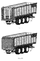
- La
Figure 1 montre un exemple de remorque comportant un dispositif suivant l'invention en position d'attente de chargement de vrac ou charge similaire. Le tapis de fond se trouve en position complètement déroulée et la paroi mobile se trouve en position frontale. - La
Figure 2 montre la remorque comportant un dispositif suivant l'invention en début de phase de déchargement. - La
Figure 3 montre les organes situés sous la baie de déchargement de la remorque. - La
Figure 4 montre la remorque comportant un dispositif suivant l'invention à peu près à mi-chemin de la phase de déchargement. - La
Figure 5 montre la remorque comportant un dispositif suivant l'invention en fin de phase de déchargement. - Les
Figures 6 ,7 et 8 montrent des vues de détail de l'avant de la remorque comportant un dispositif suivant l'invention. - La
Figure 9 montre une vue d'ensemble de la remorque comportant un dispositif suivant l'invention, certains éléments constitutifs n'ayant pas été représentés ou ne l'ayant été que partiellement afin de distinguer les organes internes. - La
Figure 10 montre un détail de la partie avant de la remorque comportant un dispositif suivant l'invention, certains éléments constitutifs n'ayant pas été représentés ou ne l'ayant été que partiellement afin de distinguer les organes internes. - La
Figure 11 montre des exemples de mise en oeuvre complémentaires d'une remorque comportant un dispositif suivant l'invention, illustrant des dispositifs de déchargement divers.
- The
Figure 1 shows an example of a trailer comprising a device according to the invention in position waiting for bulk loading or similar load. The base mat is in the fully unwound position and the movable wall is in the front position. - The
Figure 2 shows the trailer comprising a device according to the invention at the beginning of the unloading phase. - The
Figure 3 shows the bodies located under the unloading bay of the trailer. - The
Figure 4 shows the trailer comprising a device according to the invention approximately halfway to the unloading phase. - The
Figure 5 shows the trailer comprising a device according to the invention at the end of the unloading phase. - The
Figures 6 ,7 and 8 show detailed views of the front of the trailer comprising a device according to the invention. - The
Figure 9 shows an overview of the trailer comprising a device according to the invention, certain constituent elements having not been represented or only partially so as to distinguish the internal organs. - The
Figure 10 shows a detail of the front part of the trailer comprising a device according to the invention, certain constituent elements having not been represented or only partially so as to distinguish the internal organs. - The
Figure 11 shows examples of complementary implementation of a trailer comprising a device according to the invention, illustrating various unloading devices.
L'invention est explicitée à la suite au moyen d'une description non limitative de certains éléments de détail.The invention is explained below by means of a non-limiting description of certain details.
Les objectifs visés par l'invention sont atteints grâce à une caisse de transport fabriquée à partir d'une structure légère comprenant des parois latérales lisses de conception quelconque et un fond supporté par une série de traverses, elles-mêmes supportées par des longerons, lesquels peuvent faire partie du châssis porteur ou non selon que l'on conçoit la liaison de la caisse à son châssis porteur comme permanente ou non.The objectives of the invention are achieved by means of a transport case made from a light structure comprising smooth side walls of any design and a bottom supported by a series of sleepers, themselves supported by longitudinal members, which can be part of the carrier frame or not depending on whether we design the connection of the body to its carrier frame as permanent or not.
De préférence, le fond est constitué de tôles pourvues, à intervalle régulier, de vallées dans lesquelles sont réservés des orifices permettant l'évacuation des résidus éventuels qui auraient pu se glisser entre le fond et le tapis de fond.Preferably, the bottom consists of sheets provided, at regular intervals, valleys in which are reserved orifices for the evacuation of any residues that could have slipped between the bottom and the bottom mat.
De préférence également, les parois latérales s'écartent à mesure qu'elles se rapprochent de la baie de déchargement, formant une caisse dite « conique ».Also preferably, the side walls deviate as they approach the unloading bay, forming a box called "conical".
Le fond est intégralement couvert d'un tapis réalisé dans une matière dont la souplesse autorise l'enroulement du tapis autour d'un tambour et dont la résistance est compatible avec la charge utile de la remorque augmentée de la masse d'une paroi mobile de caisse (voir plus bas) et les paramètres d'agressivité du type de charge envisagée. Ce tapis peut être réalisé d'une seule pièce ou de manière sectionnelle, l'important étant que le résultat assemblé assure la couverture étanche de la surface intégrale du fond de caisse et puisse être enroulé sous forme d'un cylindre de diamètre compact. La caisse de transport comporte en outre une baie de déchargement. Dans une forme préférée mais non exclusive de l'invention, cette baie est située à l'arrière par rapport au sens normal de marche du véhicule de traction et comporte un moyen d'obturation quelconque, par exemple un panneau ou caisson mobile, une porte ouvrante à un ou plusieurs battants, un volet ouvrant par un dispositif quelconque, etc.The bottom is completely covered with a mat made of a material whose flexibility allows the winding of the belt around a drum and whose resistance is compatible with the payload of the trailer plus the mass of a movable wall of crate (see below) and aggressiveness parameters of the type of load envisaged. This carpet can be made in one piece or in sectional manner, the important thing being that the assembled result ensures the tight coverage of the integral surface of the bottom of the body and can be wound in the form of a cylinder of compact diameter. The transport case comprises in addition an unloading bay. In a preferred but non-exclusive form of the invention, this bay is located at the rear relative to the normal direction of travel of the traction vehicle and comprises any sealing means, for example a panel or mobile box, a door opening to one or more leaves, a shutter opening by any device, etc.
A l'opposé de la baie de déchargement est disposée une paroi mobile qui n'est fixée que par sa base au tapis de fond, au moyen de dispositifs de fixation adaptés. Cette paroi mobile est pourvue d'un dispositif de guidage et de maintien. Dans une forme préférée de l'invention, ce dispositif de guidage et de maintien n'utilise pas les parois latérales de la caisse parce que celles-ci sont susceptibles de se déformer à la suite de l'agression des charges transportées et/ou des véhicules de manutention procédant au remplissage de la caisse, et parce que la partie supérieure des parois latérales devrait rester libre pour y disposer un système de bâchage. Néanmoins, pour assurer l'étanchéité de la paroi mobile le long des parois latérales, deux joints sont disposés le long des arêtes verticales de la paroi mobile. Ces joints sont constitués d'une matière, telle que par exemple le caoutchouc, suffisamment dure pour résister à l'inertie et à l'abrasion de la matière transportée lorsque celle-ci est déchargée et, en cas de caisse conique, suffisamment souple pour compenser l'écartement progressif des parois latérales, la largeur des joints étant prévue en conséquence.Opposite the unloading bay is disposed a movable wall which is fixed only by its base to the base mat, by means of suitable fastening devices. This movable wall is provided with a guiding and holding device. In a preferred form of the invention, this guiding and holding device does not use the side walls of the box because these are likely to deform as a result of the aggression of the transported loads and / or handling vehicles filling the body, and because the upper part of the side walls should remain free to have a system of tarpaulin. Nevertheless, to seal the movable wall along the side walls, two joints are arranged along the vertical edges of the movable wall. These joints consist of a material, such as for example rubber, sufficiently hard to withstand the inertia and abrasion of the transported material when it is unloaded and, in case of conical body, sufficiently flexible to compensate for the progressive separation of the side walls, the width of the joints being provided accordingly.
Une forme possible du dispositif de guidage et de maintien de la paroi mobile est constituée d'un chevalet tridimensionnel disposé sur le côté de la paroi mobile qui n'est pas exposé à la charge transportée. La base s'étend plus ou moins largement à l'avant de la paroi pour guider celle-ci sur une plus ou moins grande largeur et elle s'étend de manière plus ou moins éloignée de la paroi pour soutenir la partie supérieure de celle-ci avec un angle d'appui permettant de maintenir la paroi dans sa position constructive, et de résister à la pression exercée sur la paroi mobile par la portion de la charge transportée qui lui est contiguë.One possible form of the device for guiding and holding the movable wall consists of a three-dimensional easel disposed on the side of the movable wall which is not exposed to the load transported. The base extends more or less widely in front of the wall to guide it is more or less wide and extends more or less far from the wall to support the upper part thereof with a bearing angle to maintain the wall in its constructive position, and to withstand the pressure exerted on the movable wall by the portion of the transported load which is contiguous thereto.
La base du chevalet est équipée de moyens de guidage qui se déplaceront sur ou dans un canal de guidage afin de guider le déplacement de la paroi mobile. Le canal de guidage est constitué par exemple de deux rails en forme de « L » inversé (tête en bas), disposés en vis-à-vis avec un écartement central par lequel passent les moyens de guidage à la base du chevalet. Ils sont disposés entre deux tôles de fond de caisse, de préférence légèrement écartés de ces dernières pour permettre l'évacuation des résidus éventuels.The base of the bridge is equipped with guiding means that will move on or in a guide channel to guide the movement of the movable wall. The guide channel is constituted for example by two rails in the form of an inverted "L" (head down), arranged vis-a-vis with a central spacing through which the guide means at the base of the bridge. They are arranged between two bottom sheets, preferably slightly spaced from the latter to allow the evacuation of any residues.
Dans une forme d'exécution préférée permettant aussi de faciliter le déplacement de la paroi mobile, les moyens de guidage à la base du chevalet sont avantageusement constitués d'un jeu de roulettes dont certaines, comprenant une gorge centrale, sont montées en sorte que leur gorge roule directement sur les rails du canal de guidage lorsque la paroi mobile se déplace, et d'autres, sans gorge, sont montées à une hauteur inférieure, en sorte que, lors du déplacement de la paroi mobile, elles roulent sous les rails du canal de guidage afin de guider le déplacement de la paroi mobile, d'empêcher l'oscillation de celle-ci vers la baie de déchargement et de centrer l'enroulement du tapis de fond.In a preferred embodiment also facilitating the movement of the movable wall, the guide means at the base of the bridge are advantageously constituted by a set of wheels, some of which, including a central groove, are mounted so that their groove rolls directly on the rails of the guide channel when the movable wall moves, and others, without groove, are mounted at a lower height, so that, when moving the movable wall, they roll under the rails of the guide channel for guiding movement of the movable wall, preventing oscillation thereof to the unloading bay and centering the winding of the bottom mat.
Dans une forme d'exécution préférée, les rails sous lesquels roulent les roulettes inférieures sont pourvus, du côté du passage de l'axe de support des roulettes, d'un rebord destiné à guider la roulette parfaitement dans l'axe du rail (par exemple, forme de « J » inversé).In a preferred embodiment, the rails under which roll the lower rollers are provided, on the side of the passage of the support axis of the rollers, a flange for guiding the wheel perfectly in the rail axis (for example, inverted "J" shape).
Dans une forme préférée également, les rails de guidage sont disposés de manière partiellement encastrée dans les traverses de la structure de caisse, afin de maximiser la hauteur utile de caisse. Dès lors, une découpe est pratiquée dans les traverses à l'endroit du passage du canal de guidage.In a preferred form also, the guide rails are arranged partially embedded in the sleepers of the body structure, in order to maximize the useful height of the body. Therefore, a cut is made in the sleepers at the place of the passage of the guide channel.
Dans une forme préférée également, la base de la cloison mobile ou du chevalet est pourvue d'un joint racleur en matière relativement dure, épousant le profil des tôles de fond, en sorte que lorsque la paroi mobile se déplace, les résidus éventuellement présents sous le tapis soient poussés vers les vallées du fond puis évacués par les orifices pratiqués dans ces vallées.In a preferred form also, the base of the movable partition or the bridge is provided with a scraper made of relatively hard material, matching the profile of the bottom plates, so that when the movable wall moves, the residues possibly present under the carpet are pushed towards the valleys of the bottom then evacuated by the orifices practiced in these valleys.
Les roulettes, leur nombre et leur position ne sont pas des éléments caractérisants de l'invention. Les moyens de guidage pourraient aussi bien être constitués de patins, d'ergots ou de tout autre dispositif connu de l'homme de métier et autorisant le glissement. Pour des remorques destinées au transport de charges particulièrement lourdes, on pourrait aussi prévoir plus d'un canal de guidage et un nombre supérieur de roulettes inférieures et/ou supérieures.The wheels, their number and their position are not characterizing elements of the invention. The guiding means could as well consist of pads, lugs or any other device known to those skilled in the art and allowing sliding. For trailers intended for the transport of particularly heavy loads, it could also provide more than one guide channel and a greater number of lower and / or higher rollers.
De même, la liaison de la paroi mobile au tapis est réalisée suivant un dispositif quelconque, du moment que la liaison soit suffisamment solide pour ne pas être arrachée lorsque le tapis doit entraîner la paroi mobile qui subit une pression, certes proportionnellement faible mais néanmoins réelle, de la charge transportée.Similarly, the connection of the movable wall to the carpet is performed according to any device, as long as the connection is strong enough not to be torn off when the carpet must drive the movable wall which is under pressure, although proportionally small but nevertheless real , the load transported.
L'extrémité opposée du tapis de fond est fixée au moyen d'un dispositif quelconque sur un tambour enrouleur positionné sous la structure de fond de caisse, en retrait de l'extrémité de la caisse située du côté de la baie de déchargement. Ce tambour enrouleur est fixé sur un arbre d'entraînement, lui-même entraîné par un dispositif de puissance chargé d'entraîner la rotation du tambour dans le sens de la traction du tapis.The opposite end of the base mat is fixed by means of any device on a drum drum positioned under the bottom structure, set back the end of the crate located on the side of the unloading bay. This drum drum is fixed on a drive shaft, itself driven by a power device responsible for driving the rotation of the drum in the direction of traction of the belt.
Le système de puissance d'entraînement du tambour enrouleur, appelé dans cet exposé premier système de puissance, comprend un ou plusieurs engrenages entraînés ensemble ou individuellement soit par un ou plusieurs moteurs hydrauliques ou électriques, soit par le système de puissance mécanique, hydraulique ou électrique du véhicule de traction. Le système de puissance choisi doit autoriser la rotation dans le sens opposé à l'enroulement, lorsque la paroi mobile et le tapis de fond sont retirés vers l'autre extrémité de la caisse pour préparer celle-ci à un nouveau chargement.The winding drum drive power system, referred to herein as the first power system, comprises one or more gears driven together or individually by one or more hydraulic or electric motors or by the mechanical, hydraulic or electrical power system. of the towing vehicle. The selected power system must allow rotation in the opposite direction to the winding, when the movable wall and the mat are removed to the other end of the crate to prepare it for a new load.
Afin d'assister l'enroulement du tapis de fond, en particulier en cas de charge lourde, notamment en vrac et potentiellement compactée par les cahots du roulage au transport, mais aussi de ramener la paroi mobile et le tapis de fond en position de chargement, au moins une chaîne est disposée à l'intérieur du canal de guidage en sorte qu'elle puisse tourner autour de deux pignons disposés respectivement sous chacune des deux extrémités de la caisse au moyen d'arbres transversaux. Cette chaîne n'est pas nécessairement une chaîne sans fin car sa course est limitée à la course du tapis ou de la paroi mobile. Elle est cependant liée à la base de la paroi mobile ou du chevalet de maintien à une de ses extrémités au moyen d'un dispositif de liaison rigide remplaçant l'un ou plusieurs de ses maillons et à l'autre de ses extrémités au moyen d'un tendeur. L'invention prévoit que l'un quelconque des arbres transversaux supportant les pignons précités, choisi de préférence en fonction de l'espace disponible dans la structure de fond, est entraîné par un dispositif de puissance quelconque, appelé dans cet exposé second système de puissance, permettant d'entraîner la rotation de l'arbre et, partant, de la chaîne dans les deux sens. Lors de l'enroulement du tapis pour le déchargement, ce dispositif de puissance actionne la chaîne dans le sens du déplacement du tapis. Ce faisant, la chaîne entraîne avec elle la paroi mobile et donc l'extrémité du tapis opposée à son tambour d'enroulement. En conséquence, le tapis est tiré par ses deux extrémités et le dispositif permet de déplacer et décharger les charges les plus lourdes et les plus compactes, bien entendu dans les limites de la résistance de la structure de la caisse et du châssis avec train roulant qui la supporte.In order to assist the winding of the bottom mat, in particular in the case of a heavy load, in particular in bulk and potentially compacted by the jolts of the rolling to the transport, but also to bring back the movable wall and the bottom mat in the loading position at least one chain is arranged inside the guide channel so that it can rotate around two gears disposed respectively at each of the two ends of the box by means of transverse shafts. This chain is not necessarily an endless chain because its stroke is limited to the stroke of the carpet or the moving wall. However, it is connected to the base of the movable wall or of the holding bridge at one of its ends by means of a rigid connecting device replacing one or more of its links and at the other end thereof by means of 'a tensioner. The invention provides that any of the transverse shafts supporting the aforementioned pinions, preferably selected from function of the space available in the bottom structure, is driven by any power device, called in this second power system presentation, to drive the rotation of the shaft and hence the chain in both meaning. When winding the carpet for unloading, this power device actuates the chain in the direction of movement of the carpet. In doing so, the chain carries with it the movable wall and therefore the end of the carpet opposite to its winding drum. As a result, the carpet is pulled by its two ends and the device makes it possible to move and unload the heavier and more compact loads, of course within the limits of the strength of the body structure and chassis with undercarriage which support it.
Le second système de puissance peut être indépendant du premier, tant qu'il est synchronisé avec celui-ci. A titre d'exemple, on peut utiliser deux moteurs hydrauliques alimentés par le même circuit, l'huile s'équilibrant d'elle-même entre le moteur de l'enrouleur et celui de la chaîne suivant la demande de chacun des systèmes.The second power system may be independent of the first as long as it is synchronized with it. By way of example, it is possible to use two hydraulic motors powered by the same circuit, the oil balancing itself between the motor of the winder and that of the chain according to the demand of each of the systems.
Le type et le nombre de chaînes, de pignons et de liaisons de la chaîne à la paroi mobile ne sont pas des éléments caractérisants de l'invention. Dans une forme préférée d'exécution, le dispositif comprend une chaîne unique liée à la base du chevalet de maintien et guidage de la paroi mobile au moyen d'une pièce de liaison englobant aussi le ou les axes de maintien des roulettes de guidage inférieures. La puissance d'assistance au déchargement s'exerce ainsi au niveau de l'élément empêchant le basculement de la paroi mobile vers la matière transportée, en sorte que la paroi n'est pas amenée à pousser sur la matière et se confine à son rôle de maintien de la matière.The type and number of chains, sprockets and links of the chain to the movable wall are not characterizing elements of the invention. In a preferred embodiment, the device comprises a single chain connected to the base of the bridge for holding and guiding the movable wall by means of a connecting piece also including the or the axes of maintenance of the lower guide rollers. The unloading assistance power is thus exerted on the element preventing the tilting of the movable wall towards the material transported, so that the wall is not caused to push on the material and confines itself to its role. keeping the material.
Après le déchargement, le second dispositif de puissance actionne la chaîne dans le sens opposé en sorte que la paroi mobile et le tapis sont ramenés vers l'extrémité opposée à la baie de déchargement, en position d'attente pour recevoir un nouveau chargement.After unloading, the second power device operates the chain in the opposite direction so that the movable wall and the belt are brought to the end opposite the unloading bay, in the waiting position to receive a new load.
Dans la description qui suit, des éléments similaires dans les illustrations sont affectés dans la mesure du possible de repères numériques identiques. Toutes les dimensions décrites ou suggérées ici ne sont pas destinées à limiter la portée de l'invention, laquelle peut s'écarter de ces dimensions.In the following description, similar elements in the illustrations are affected as far as possible by identical numerical references. All dimensions described or suggested herein are not intended to limit the scope of the invention, which may deviate from these dimensions.
La
La
La
La
La
La
La
La paroi mobile 6 est composée d'une cloison 17 réalisée ici à l'aide d'une structure composée par exemple d'un cadre renforcé d'une ou plusieurs traverses et couverte d'une plaque 10 réalisée par exemple en polymère thermoplastique transparent (raison pour laquelle les espaces situés entre le cadre et les traverses paraissent vides sur la
La paroi mobile 6 comporte en outre un dispositif de fixation 18 qui la solidarise avec le tapis de fond 9. A nouveau, la construction de ce dispositif de fixation 18 n'est pas caractérisant, étant entendu qu'il doit être en état d'assurer durablement la traction uniforme de la paroi mobile 6 par le tapis de fond 9. The
La paroi mobile 6 comporte encore un chevalet de guidage et de maintien 19 qui, comme l'indique sa dénomination, est destiné à maintenir la paroi mobile 6 continuellement perpendiculaire aux parois latérales 4, ce qui aura pour effet secondaire de garantir l'enroulement régulier et en ligne du tapis de fond 9, et de maintenir la paroi mobile 6 dans l'angle de sa construction, c'est-à-dire de l'empêcher de basculer ou osciller d'avant en arrière et vice-versa sous l'effet de la pression de la charge transportée et/ou de son propre déplacement et/ou de toute autre force prévisible quelconque (vent, prise au vent, etc.).The
Une modalité d'exécution possible du dispositif de guidage et maintien du chevalet 19 est explicitée dans les
En
La
La
La
La
L'une des extrémités de la chaîne 27 est fixée au tendeur 34, intégré au chevalet 19, l'autre extrémité étant fixée à la pièce de liaison 30, elle-même également fixée au chevalet 19. Le tendeur 24 permet de compenser l'allongement de la chaîne 27 qui se produit, lorsque celle-ci est mise en mouvement, sous l'effet de la traction exercée par le pignon d'entraînement 28. En début de cycle de déchargement, l'effort de traction affecte en effet la longueur quasi totale de la chaîne 27, depuis les maillons situés autour du pignon d'entraînement 28 jusqu'au maillon fixé à la pièce de liaison 30. Suivant la masse à déplacer, la chaîne 27 peut alors s'allonger de plusieurs centimètres qui seront compensés par l'extension des ressorts 35 du tendeur 34. Lorsque le pignon d'entraînement 28 entraîne le tapis de fond 9 vers la baie de déchargement, les ressorts 35 du tendeur 34 sont en effet soulagés de la traction de la chaîne 27, celle-ci n'étant plus soumise à contrainte de traction dans sa portion comprise entre le maillon situé à la sortie du pignon d'entraînement 28 et le maillon fixé au tendeur 34. Cet allongement de la chaîne 27 diminue au fur et à mesure que le chevalet 19 de la paroi mobile 6 se déplace vers la baie de déchargement, la portion de chaîne 27 soumise à la contrainte de traction diminuant concomitamment.One end of the
En
- en
Figure 11A , une application dans le cas d'un épandeur de fumier; - en
Figure 11B , une application dans le cas d'un épandeur à plateaux pour engrais, sel, sable, chaux ou autre matière à structure granuleuse;
- en
Figure 11C , une application dans le cas d'une remorque distributrice de fourrage avec turbine de déchiquetage et projection à l'arrière de la remorque; - en
Figure 11D , une application dans le cas d'une remorque de transbordement équipée d'une trémie arrière dirigeant la matière déversée vers une vis sans fin qui la transfère vers un autre engin.
- in
Figure 11A , an application in the case of a manure spreader; - in
Figure 11B , an application in the case of a spreader with trays for fertilizer, salt, sand, lime or other material with a granular structure;
- in
Figure 11C , an application in the case of a fodder distribution trailer with shredding turbine and projection at the rear of the trailer; - in
Figure 11D , an application in the case of a transhipment trailer equipped with a rear hopper directing the spilled material to a worm which transfers it to another machine.
Ces exemples ne sont nullement limitatifs : ils peuvent être étendus aussi loin que l'imagination de l'homme peut adjoindre un ou plusieurs accessoires au dispositif de déchargement.These examples are in no way limiting: they can be extended as far as the imagination of the man can add one or more accessories to the unloading device.
Nonobstant le fait que la présente invention a été exposée au moyen d'une description détaillée dans laquelle différentes variantes d'exécution et différents aspects de l'invention ont été explicités, l'homme de l'art verra que la portée complète de l'invention n'est nullement limitée aux exemples présentés ici. L'invention a une portée qui est proportionnelle aux revendications du présent brevet, incluant tous éléments ou aspects qui seraient considérés comme équivalents à ceux exposés dans les revendications principales ou dépendantes.Notwithstanding the fact that the present invention has been set forth by means of a detailed description in which various alternative embodiments and different aspects of the invention have been made explicit, one skilled in the art will see that the full scope of the invention The invention is in no way limited to the examples presented here. The invention has a scope that is proportional to the claims of this patent, including any elements or aspects that would be considered equivalent to those set forth in the main or dependent claims.
- 1.1.
- Caisse de chargementLoading box
- 2.2.
- ChâssisFrame
- 3.3.
- Timonshaft
- 4.4.
- Parois latéralesLateral walls
- 5.5.
- Porte arrièreBack door
- 6.6.
- Paroi mobileMobile wall
- 7.7.
- Structure de fond de caisseCash desk structure
- 8.8.
- Vérins de porte arrièreRear door cylinders
- 9.9.
- Tapis de fondCarpet background
- 10.10.
- Plaque transparenteTransparent plate
- 11.11.
- Tambour d'enroulementWinding drum
- 12.12.
- Engrenage de tambourDrum gear
- 13.13.
- Moteur hydraulique (1er système de puissance)Hydraulic motor ( 1st power system)
- 14.14.
- Tambour de renvoiDrum of return
- 15.15.
- RacloirScraper
- 16.16.
- Support de racloirScraper holder
- 17.17.
- Cloison de paroi mobileMobile wall partition
- 18.18.
- Dispositif de fixation de la paroi mobile au tapisDevice for fixing the mobile wall to the carpet
- 19.19.
- Chevalet de guidage et maintienGuiding easel and support
- 20.20.
- Joint racleurWiper seal
- 21.21.
- Roulettes supérieuresUpper wheels
- 22.22.
- Rails de guidageGuide rails
- 23.23.
- Roulettes inférieuresLower casters
- 24.24.
- Canal de guidageGuide channel
- 25.25.
- Capot de protectionProtective cover
- 26.26.
- Écrou de réglageAdjusting nut
- 27.27.
- ChaîneChain
- 28.28.
- Pignon d'entraînementDrive sprocket
- 29.29.
- Pignon de renvoiDeflection pinion
- 30.30.
- Pièce de liaisonConnecting piece
- 31.31.
- Engrenagegearing
- 32.32.
- Moteur hydraulique (2ème système de puissance)Hydraulic motor ( 2nd power system)
- 33.33.
- Palier de roulette inférieureLower roller bearing
- 34.34.
- Tendeur de chaîneChain tensioner
- 35.35.
- Ressort(s)Spring (s)
- 36.36.
- Vallée de fond de caisseBottom valley
Claims (17)
Priority Applications (1)
| Application Number | Priority Date | Filing Date | Title |
|---|---|---|---|
| PL15197074T PL3028895T3 (en) | 2014-12-05 | 2015-11-30 | Device to assist with unloading a transport trailer with roller conveyor |
Applications Claiming Priority (1)
| Application Number | Priority Date | Filing Date | Title |
|---|---|---|---|
| BE20145104A BE1022616A9 (en) | 2014-12-05 | 2014-12-05 | DEVICE FOR ASSISTING THE UNLOADING OF A TRANSPORT TRAILER WITH A ROLLER BELT |
Publications (2)
| Publication Number | Publication Date |
|---|---|
| EP3028895A1 true EP3028895A1 (en) | 2016-06-08 |
| EP3028895B1 EP3028895B1 (en) | 2017-09-27 |
Family
ID=52736783
Family Applications (1)
| Application Number | Title | Priority Date | Filing Date |
|---|---|---|---|
| EP15197074.6A Active EP3028895B1 (en) | 2014-12-05 | 2015-11-30 | Device to assist with unloading a transport trailer with roller conveyor |
Country Status (4)
| Country | Link |
|---|---|
| EP (1) | EP3028895B1 (en) |
| BE (1) | BE1022616A9 (en) |
| ES (1) | ES2648807T3 (en) |
| PL (1) | PL3028895T3 (en) |
Cited By (2)
| Publication number | Priority date | Publication date | Assignee | Title |
|---|---|---|---|---|
| CN107444934A (en) * | 2017-05-18 | 2017-12-08 | 威海顺丰专用车制造有限公司 | A kind of vehicle-mounted bulk goods self-discharging system |
| CN113525208A (en) * | 2021-08-16 | 2021-10-22 | 山东亚中车辆股份有限公司 | Special vehicle |
Families Citing this family (1)
| Publication number | Priority date | Publication date | Assignee | Title |
|---|---|---|---|---|
| DE102017115419A1 (en) * | 2017-07-10 | 2019-01-10 | Langendorf Gmbh | Vehicle body with sliding belt unit |
Citations (6)
| Publication number | Priority date | Publication date | Assignee | Title |
|---|---|---|---|---|
| US3498482A (en) | 1968-07-30 | 1970-03-03 | Western Sawdust Products Inc | Truck-body unloading apparatus |
| DE20117346U1 (en) | 2001-08-25 | 2002-03-28 | Annaburger Nutzfahrzeug Gmbh | Loader wagon with unloading device |
| US6837668B1 (en) * | 1999-06-15 | 2005-01-04 | Multidrive Limited | Load carrying body |
| US20110142585A1 (en) * | 2009-12-10 | 2011-06-16 | Harvey Stewart | Light-weight live-floor module for trailers |
| EP2497684A1 (en) | 2011-03-10 | 2012-09-12 | Ets JOSKIN S.A. | Transport trailer with unloading by a winding conveyor |
| JP5328228B2 (en) | 2008-05-26 | 2013-10-30 | 株式会社立和運輸倉庫 | Vehicle handling equipment |
-
2014
- 2014-12-05 BE BE20145104A patent/BE1022616A9/en not_active IP Right Cessation
-
2015
- 2015-11-30 PL PL15197074T patent/PL3028895T3/en unknown
- 2015-11-30 EP EP15197074.6A patent/EP3028895B1/en active Active
- 2015-11-30 ES ES15197074.6T patent/ES2648807T3/en active Active
Patent Citations (6)
| Publication number | Priority date | Publication date | Assignee | Title |
|---|---|---|---|---|
| US3498482A (en) | 1968-07-30 | 1970-03-03 | Western Sawdust Products Inc | Truck-body unloading apparatus |
| US6837668B1 (en) * | 1999-06-15 | 2005-01-04 | Multidrive Limited | Load carrying body |
| DE20117346U1 (en) | 2001-08-25 | 2002-03-28 | Annaburger Nutzfahrzeug Gmbh | Loader wagon with unloading device |
| JP5328228B2 (en) | 2008-05-26 | 2013-10-30 | 株式会社立和運輸倉庫 | Vehicle handling equipment |
| US20110142585A1 (en) * | 2009-12-10 | 2011-06-16 | Harvey Stewart | Light-weight live-floor module for trailers |
| EP2497684A1 (en) | 2011-03-10 | 2012-09-12 | Ets JOSKIN S.A. | Transport trailer with unloading by a winding conveyor |
Cited By (2)
| Publication number | Priority date | Publication date | Assignee | Title |
|---|---|---|---|---|
| CN107444934A (en) * | 2017-05-18 | 2017-12-08 | 威海顺丰专用车制造有限公司 | A kind of vehicle-mounted bulk goods self-discharging system |
| CN113525208A (en) * | 2021-08-16 | 2021-10-22 | 山东亚中车辆股份有限公司 | Special vehicle |
Also Published As
| Publication number | Publication date |
|---|---|
| PL3028895T3 (en) | 2018-04-30 |
| ES2648807T3 (en) | 2018-01-08 |
| BE1022616A1 (en) | 2016-06-16 |
| EP3028895B1 (en) | 2017-09-27 |
| BE1022616A9 (en) | 2016-10-07 |
| BE1022616B1 (en) | 2016-06-16 |
Similar Documents
| Publication | Publication Date | Title |
|---|---|---|
| EP1742858B1 (en) | Installation and method for transferring a load between a transfer platform and a transport vehicle | |
| EP3028895B1 (en) | Device to assist with unloading a transport trailer with roller conveyor | |
| CH398456A (en) | Container for storing or transporting materials or goods | |
| EP2497684A1 (en) | Transport trailer with unloading by a winding conveyor | |
| EP3749548B1 (en) | Materials transport vehicle | |
| EP2070850B1 (en) | Installation for loading divided products in skips | |
| EP3687856B1 (en) | Loading platform for a car with sliding crossmember of basket type | |
| EP2878551B1 (en) | Device for lateral tarping/detarping of a bin, vehicle and bin therewith | |
| WO2012107653A1 (en) | Compactor bin for collecting a load of the household waste type, and method for transferring the load from such a bin to a container | |
| EP2493714B1 (en) | Device for automatically unwinding and winding up a tarpaulin | |
| FR2668785A1 (en) | Machine for continuous collection and storage of detached rail fastening means | |
| FR2902379A1 (en) | Tarpaulin displacement device for e.g. truck body, has load bar guided in translation by rail at bar`s end so that bar is only supported by end, carriage with rollers engaged with rail, and manual drive mechanism driving bar in movement | |
| EP2481639B1 (en) | Lining for rear-unloading dump truck body, equipped with such a lining and loading/unloading method therefore | |
| FR2795709A1 (en) | Storage module for articles comprises shelves with suspension assemblies using bars arranged through loops in flexible straps with synchronized vertical movement. | |
| FR2908092A1 (en) | Heavy object e.g. motor cycle, loading and unloading device for e.g. trailer, has guiding unit guiding ramp between two positions and bringing back ramp above floor, when ramp reaches loading/unloading position | |
| FR2978434A1 (en) | Motorized vehicle i.e. lorry, and transport bin assembly, for transporting wastes in e.g. construction field, has bin comprising support paths opened longitudinally forwards for introduction of arm by longitudinal displacement of vehicle | |
| EP1588894A1 (en) | Towable device supporting a removable bucket | |
| FR3099145A1 (en) | MOVING BOTTOM LOADING BOX AND MOBILE UNLOADING BULKHEAD IN TRANSLATION | |
| FR3023253A1 (en) | TRAILER WITH VARIABLE HEIGHT BENCH AND INDEPENDENT CONVEYOR TRAY | |
| BE1019730A3 (en) | PACKAGING DEVICE FOR AGRICULTURAL PRODUCTS, ESPECIALLY LEEKS. | |
| WO2021053274A1 (en) | Device for launching a floating object from a vehicle, and associated vehicle | |
| FR3032662A1 (en) | BENCH COMPRISING A REMOVABLE DISTRIBUTION MODULE AND ASSOCIATED DISTRIBUTION MODULE | |
| FR3032696A1 (en) | MODULE FOR DISTRIBUTING A DUMP AND TANK EQUIPPED WITH SUCH A MODULE | |
| FR2941219A1 (en) | VEHICLE EQUIPPED WITH HANDLING SYSTEM FOR REMOVABLE CONTAINERS | |
| EP1444151A1 (en) | Rapid loading and unloading device for road/rail transport with a feed belt conveyor using a hydraulic jack |
Legal Events
| Date | Code | Title | Description |
|---|---|---|---|
| PUAI | Public reference made under article 153(3) epc to a published international application that has entered the european phase |
Free format text: ORIGINAL CODE: 0009012 |
|
| AK | Designated contracting states |
Kind code of ref document: A1 Designated state(s): AL AT BE BG CH CY CZ DE DK EE ES FI FR GB GR HR HU IE IS IT LI LT LU LV MC MK MT NL NO PL PT RO RS SE SI SK SM TR |
|
| AX | Request for extension of the european patent |
Extension state: BA ME |
|
| 17P | Request for examination filed |
Effective date: 20161123 |
|
| RBV | Designated contracting states (corrected) |
Designated state(s): AL AT BE BG CH CY CZ DE DK EE ES FI FR GB GR HR HU IE IS IT LI LT LU LV MC MK MT NL NO PL PT RO RS SE SI SK SM TR |
|
| GRAP | Despatch of communication of intention to grant a patent |
Free format text: ORIGINAL CODE: EPIDOSNIGR1 |
|
| INTG | Intention to grant announced |
Effective date: 20170322 |
|
| GRAS | Grant fee paid |
Free format text: ORIGINAL CODE: EPIDOSNIGR3 |
|
| GRAJ | Information related to disapproval of communication of intention to grant by the applicant or resumption of examination proceedings by the epo deleted |
Free format text: ORIGINAL CODE: EPIDOSDIGR1 |
|
| GRAL | Information related to payment of fee for publishing/printing deleted |
Free format text: ORIGINAL CODE: EPIDOSDIGR3 |
|
| GRAP | Despatch of communication of intention to grant a patent |
Free format text: ORIGINAL CODE: EPIDOSNIGR1 |
|
| INTC | Intention to grant announced (deleted) | ||
| GRAA | (expected) grant |
Free format text: ORIGINAL CODE: 0009210 |
|
| INTG | Intention to grant announced |
Effective date: 20170808 |
|
| AK | Designated contracting states |
Kind code of ref document: B1 Designated state(s): AL AT BE BG CH CY CZ DE DK EE ES FI FR GB GR HR HU IE IS IT LI LT LU LV MC MK MT NL NO PL PT RO RS SE SI SK SM TR |
|
| REG | Reference to a national code |
Ref country code: GB Ref legal event code: FG4D Free format text: NOT ENGLISH |
|
| REG | Reference to a national code |
Ref country code: CH Ref legal event code: EP |
|
| REG | Reference to a national code |
Ref country code: AT Ref legal event code: REF Ref document number: 931632 Country of ref document: AT Kind code of ref document: T Effective date: 20171015 |
|
| REG | Reference to a national code |
Ref country code: IE Ref legal event code: FG4D Free format text: LANGUAGE OF EP DOCUMENT: FRENCH |
|
| REG | Reference to a national code |
Ref country code: FR Ref legal event code: PLFP Year of fee payment: 3 |
|
| REG | Reference to a national code |
Ref country code: DE Ref legal event code: R096 Ref document number: 602015004994 Country of ref document: DE |
|
| REG | Reference to a national code |
Ref country code: ES Ref legal event code: FG2A Ref document number: 2648807 Country of ref document: ES Kind code of ref document: T3 Effective date: 20180108 |
|
| REG | Reference to a national code |
Ref country code: NL Ref legal event code: FP |
|
| PG25 | Lapsed in a contracting state [announced via postgrant information from national office to epo] |
Ref country code: HR Free format text: LAPSE BECAUSE OF FAILURE TO SUBMIT A TRANSLATION OF THE DESCRIPTION OR TO PAY THE FEE WITHIN THE PRESCRIBED TIME-LIMIT Effective date: 20170927 Ref country code: FI Free format text: LAPSE BECAUSE OF FAILURE TO SUBMIT A TRANSLATION OF THE DESCRIPTION OR TO PAY THE FEE WITHIN THE PRESCRIBED TIME-LIMIT Effective date: 20170927 Ref country code: NO Free format text: LAPSE BECAUSE OF FAILURE TO SUBMIT A TRANSLATION OF THE DESCRIPTION OR TO PAY THE FEE WITHIN THE PRESCRIBED TIME-LIMIT Effective date: 20171227 Ref country code: LT Free format text: LAPSE BECAUSE OF FAILURE TO SUBMIT A TRANSLATION OF THE DESCRIPTION OR TO PAY THE FEE WITHIN THE PRESCRIBED TIME-LIMIT Effective date: 20170927 Ref country code: SE Free format text: LAPSE BECAUSE OF FAILURE TO SUBMIT A TRANSLATION OF THE DESCRIPTION OR TO PAY THE FEE WITHIN THE PRESCRIBED TIME-LIMIT Effective date: 20170927 |
|
| REG | Reference to a national code |
Ref country code: LT Ref legal event code: MG4D |
|
| REG | Reference to a national code |
Ref country code: AT Ref legal event code: MK05 Ref document number: 931632 Country of ref document: AT Kind code of ref document: T Effective date: 20170927 |
|
| PG25 | Lapsed in a contracting state [announced via postgrant information from national office to epo] |
Ref country code: RS Free format text: LAPSE BECAUSE OF FAILURE TO SUBMIT A TRANSLATION OF THE DESCRIPTION OR TO PAY THE FEE WITHIN THE PRESCRIBED TIME-LIMIT Effective date: 20170927 Ref country code: GR Free format text: LAPSE BECAUSE OF FAILURE TO SUBMIT A TRANSLATION OF THE DESCRIPTION OR TO PAY THE FEE WITHIN THE PRESCRIBED TIME-LIMIT Effective date: 20171228 Ref country code: BG Free format text: LAPSE BECAUSE OF FAILURE TO SUBMIT A TRANSLATION OF THE DESCRIPTION OR TO PAY THE FEE WITHIN THE PRESCRIBED TIME-LIMIT Effective date: 20171227 Ref country code: LV Free format text: LAPSE BECAUSE OF FAILURE TO SUBMIT A TRANSLATION OF THE DESCRIPTION OR TO PAY THE FEE WITHIN THE PRESCRIBED TIME-LIMIT Effective date: 20170927 |
|
| PG25 | Lapsed in a contracting state [announced via postgrant information from national office to epo] |
Ref country code: CZ Free format text: LAPSE BECAUSE OF FAILURE TO SUBMIT A TRANSLATION OF THE DESCRIPTION OR TO PAY THE FEE WITHIN THE PRESCRIBED TIME-LIMIT Effective date: 20170927 Ref country code: RO Free format text: LAPSE BECAUSE OF FAILURE TO SUBMIT A TRANSLATION OF THE DESCRIPTION OR TO PAY THE FEE WITHIN THE PRESCRIBED TIME-LIMIT Effective date: 20170927 |
|
| PG25 | Lapsed in a contracting state [announced via postgrant information from national office to epo] |
Ref country code: IS Free format text: LAPSE BECAUSE OF FAILURE TO SUBMIT A TRANSLATION OF THE DESCRIPTION OR TO PAY THE FEE WITHIN THE PRESCRIBED TIME-LIMIT Effective date: 20180127 Ref country code: SM Free format text: LAPSE BECAUSE OF FAILURE TO SUBMIT A TRANSLATION OF THE DESCRIPTION OR TO PAY THE FEE WITHIN THE PRESCRIBED TIME-LIMIT Effective date: 20170927 Ref country code: AT Free format text: LAPSE BECAUSE OF FAILURE TO SUBMIT A TRANSLATION OF THE DESCRIPTION OR TO PAY THE FEE WITHIN THE PRESCRIBED TIME-LIMIT Effective date: 20170927 Ref country code: SK Free format text: LAPSE BECAUSE OF FAILURE TO SUBMIT A TRANSLATION OF THE DESCRIPTION OR TO PAY THE FEE WITHIN THE PRESCRIBED TIME-LIMIT Effective date: 20170927 Ref country code: EE Free format text: LAPSE BECAUSE OF FAILURE TO SUBMIT A TRANSLATION OF THE DESCRIPTION OR TO PAY THE FEE WITHIN THE PRESCRIBED TIME-LIMIT Effective date: 20170927 |
|
| REG | Reference to a national code |
Ref country code: DE Ref legal event code: R097 Ref document number: 602015004994 Country of ref document: DE |
|
| PG25 | Lapsed in a contracting state [announced via postgrant information from national office to epo] |
Ref country code: MC Free format text: LAPSE BECAUSE OF FAILURE TO SUBMIT A TRANSLATION OF THE DESCRIPTION OR TO PAY THE FEE WITHIN THE PRESCRIBED TIME-LIMIT Effective date: 20170927 |
|
| PG25 | Lapsed in a contracting state [announced via postgrant information from national office to epo] |
Ref country code: DK Free format text: LAPSE BECAUSE OF FAILURE TO SUBMIT A TRANSLATION OF THE DESCRIPTION OR TO PAY THE FEE WITHIN THE PRESCRIBED TIME-LIMIT Effective date: 20170927 |
|
| PLBE | No opposition filed within time limit |
Free format text: ORIGINAL CODE: 0009261 |
|
| STAA | Information on the status of an ep patent application or granted ep patent |
Free format text: STATUS: NO OPPOSITION FILED WITHIN TIME LIMIT |
|
| PG25 | Lapsed in a contracting state [announced via postgrant information from national office to epo] |
Ref country code: LU Free format text: LAPSE BECAUSE OF NON-PAYMENT OF DUE FEES Effective date: 20171130 |
|
| 26N | No opposition filed |
Effective date: 20180628 |
|
| PG25 | Lapsed in a contracting state [announced via postgrant information from national office to epo] |
Ref country code: MT Free format text: LAPSE BECAUSE OF FAILURE TO SUBMIT A TRANSLATION OF THE DESCRIPTION OR TO PAY THE FEE WITHIN THE PRESCRIBED TIME-LIMIT Effective date: 20170927 |
|
| REG | Reference to a national code |
Ref country code: FR Ref legal event code: PLFP Year of fee payment: 4 |
|
| PG25 | Lapsed in a contracting state [announced via postgrant information from national office to epo] |
Ref country code: SI Free format text: LAPSE BECAUSE OF FAILURE TO SUBMIT A TRANSLATION OF THE DESCRIPTION OR TO PAY THE FEE WITHIN THE PRESCRIBED TIME-LIMIT Effective date: 20170927 |
|
| PG25 | Lapsed in a contracting state [announced via postgrant information from national office to epo] |
Ref country code: HU Free format text: LAPSE BECAUSE OF FAILURE TO SUBMIT A TRANSLATION OF THE DESCRIPTION OR TO PAY THE FEE WITHIN THE PRESCRIBED TIME-LIMIT; INVALID AB INITIO Effective date: 20151130 |
|
| REG | Reference to a national code |
Ref country code: CH Ref legal event code: PL |
|
| PG25 | Lapsed in a contracting state [announced via postgrant information from national office to epo] |
Ref country code: LI Free format text: LAPSE BECAUSE OF NON-PAYMENT OF DUE FEES Effective date: 20181130 Ref country code: CH Free format text: LAPSE BECAUSE OF NON-PAYMENT OF DUE FEES Effective date: 20181130 |
|
| PG25 | Lapsed in a contracting state [announced via postgrant information from national office to epo] |
Ref country code: CY Free format text: LAPSE BECAUSE OF FAILURE TO SUBMIT A TRANSLATION OF THE DESCRIPTION OR TO PAY THE FEE WITHIN THE PRESCRIBED TIME-LIMIT Effective date: 20170927 |
|
| PG25 | Lapsed in a contracting state [announced via postgrant information from national office to epo] |
Ref country code: MK Free format text: LAPSE BECAUSE OF FAILURE TO SUBMIT A TRANSLATION OF THE DESCRIPTION OR TO PAY THE FEE WITHIN THE PRESCRIBED TIME-LIMIT Effective date: 20170927 |
|
| PG25 | Lapsed in a contracting state [announced via postgrant information from national office to epo] |
Ref country code: TR Free format text: LAPSE BECAUSE OF FAILURE TO SUBMIT A TRANSLATION OF THE DESCRIPTION OR TO PAY THE FEE WITHIN THE PRESCRIBED TIME-LIMIT Effective date: 20170927 |
|
| PG25 | Lapsed in a contracting state [announced via postgrant information from national office to epo] |
Ref country code: PT Free format text: LAPSE BECAUSE OF FAILURE TO SUBMIT A TRANSLATION OF THE DESCRIPTION OR TO PAY THE FEE WITHIN THE PRESCRIBED TIME-LIMIT Effective date: 20170927 |
|
| PG25 | Lapsed in a contracting state [announced via postgrant information from national office to epo] |
Ref country code: AL Free format text: LAPSE BECAUSE OF FAILURE TO SUBMIT A TRANSLATION OF THE DESCRIPTION OR TO PAY THE FEE WITHIN THE PRESCRIBED TIME-LIMIT Effective date: 20170927 |
|
| PGFP | Annual fee paid to national office [announced via postgrant information from national office to epo] |
Ref country code: NL Payment date: 20231020 Year of fee payment: 9 |
|
| PGFP | Annual fee paid to national office [announced via postgrant information from national office to epo] |
Ref country code: GB Payment date: 20231019 Year of fee payment: 9 |
|
| PGFP | Annual fee paid to national office [announced via postgrant information from national office to epo] |
Ref country code: ES Payment date: 20231201 Year of fee payment: 9 |
|
| PGFP | Annual fee paid to national office [announced via postgrant information from national office to epo] |
Ref country code: IT Payment date: 20231019 Year of fee payment: 9 Ref country code: IE Payment date: 20231023 Year of fee payment: 9 Ref country code: FR Payment date: 20231020 Year of fee payment: 9 Ref country code: DE Payment date: 20231019 Year of fee payment: 9 |
|
| PGFP | Annual fee paid to national office [announced via postgrant information from national office to epo] |
Ref country code: PL Payment date: 20231020 Year of fee payment: 9 Ref country code: BE Payment date: 20231019 Year of fee payment: 9 |