EP3028881A1 - Filter for a pneumatic tire - Google Patents
Filter for a pneumatic tire Download PDFInfo
- Publication number
- EP3028881A1 EP3028881A1 EP15197123.1A EP15197123A EP3028881A1 EP 3028881 A1 EP3028881 A1 EP 3028881A1 EP 15197123 A EP15197123 A EP 15197123A EP 3028881 A1 EP3028881 A1 EP 3028881A1
- Authority
- EP
- European Patent Office
- Prior art keywords
- tire
- air
- filter
- tube
- groove
- Prior art date
- Legal status (The legal status is an assumption and is not a legal conclusion. Google has not performed a legal analysis and makes no representation as to the accuracy of the status listed.)
- Granted
Links
- 239000000463 material Substances 0.000 claims abstract description 39
- 230000002209 hydrophobic effect Effects 0.000 claims abstract description 16
- 239000003570 air Substances 0.000 claims description 132
- 239000012528 membrane Substances 0.000 claims description 42
- 239000007788 liquid Substances 0.000 claims description 17
- 238000005452 bending Methods 0.000 claims description 11
- 238000001914 filtration Methods 0.000 claims description 9
- 238000000034 method Methods 0.000 claims description 9
- 238000005096 rolling process Methods 0.000 claims description 9
- -1 polytetrafluoroethylene Polymers 0.000 claims description 8
- 229920001343 polytetrafluoroethylene Polymers 0.000 claims description 7
- 239000004810 polytetrafluoroethylene Substances 0.000 claims description 7
- 230000004044 response Effects 0.000 claims description 6
- 238000007789 sealing Methods 0.000 claims description 4
- 239000012080 ambient air Substances 0.000 claims description 3
- 239000011324 bead Substances 0.000 claims description 3
- 230000002572 peristaltic effect Effects 0.000 description 10
- XLYOFNOQVPJJNP-UHFFFAOYSA-N water Substances O XLYOFNOQVPJJNP-UHFFFAOYSA-N 0.000 description 9
- 230000006835 compression Effects 0.000 description 7
- 238000007906 compression Methods 0.000 description 7
- 239000004033 plastic Substances 0.000 description 7
- 229920003023 plastic Polymers 0.000 description 7
- 238000005086 pumping Methods 0.000 description 7
- 238000004140 cleaning Methods 0.000 description 5
- 238000003780 insertion Methods 0.000 description 5
- 230000037431 insertion Effects 0.000 description 5
- 239000000126 substance Substances 0.000 description 5
- 238000012423 maintenance Methods 0.000 description 4
- 230000009467 reduction Effects 0.000 description 3
- 239000003981 vehicle Substances 0.000 description 3
- 230000001413 cellular effect Effects 0.000 description 2
- 230000000295 complement effect Effects 0.000 description 2
- 238000004519 manufacturing process Methods 0.000 description 2
- 239000002184 metal Substances 0.000 description 2
- 238000012544 monitoring process Methods 0.000 description 2
- 239000002245 particle Substances 0.000 description 2
- 239000011148 porous material Substances 0.000 description 2
- 239000004952 Polyamide Substances 0.000 description 1
- 239000004698 Polyethylene Substances 0.000 description 1
- 239000004743 Polypropylene Substances 0.000 description 1
- 239000004809 Teflon Substances 0.000 description 1
- 229920006362 Teflon® Polymers 0.000 description 1
- 150000001335 aliphatic alkanes Chemical class 0.000 description 1
- 230000008901 benefit Effects 0.000 description 1
- 230000000903 blocking effect Effects 0.000 description 1
- 239000011248 coating agent Substances 0.000 description 1
- 238000000576 coating method Methods 0.000 description 1
- 239000002131 composite material Substances 0.000 description 1
- 150000001875 compounds Chemical class 0.000 description 1
- 238000010276 construction Methods 0.000 description 1
- 230000008602 contraction Effects 0.000 description 1
- 230000007797 corrosion Effects 0.000 description 1
- 238000005260 corrosion Methods 0.000 description 1
- 230000008878 coupling Effects 0.000 description 1
- 238000010168 coupling process Methods 0.000 description 1
- 238000005859 coupling reaction Methods 0.000 description 1
- 230000006378 damage Effects 0.000 description 1
- 230000001419 dependent effect Effects 0.000 description 1
- 238000009792 diffusion process Methods 0.000 description 1
- 238000009826 distribution Methods 0.000 description 1
- 230000000694 effects Effects 0.000 description 1
- 238000005516 engineering process Methods 0.000 description 1
- 239000003925 fat Substances 0.000 description 1
- 238000011010 flushing procedure Methods 0.000 description 1
- 239000000446 fuel Substances 0.000 description 1
- 230000006872 improvement Effects 0.000 description 1
- 238000005304 joining Methods 0.000 description 1
- 230000004048 modification Effects 0.000 description 1
- 238000012986 modification Methods 0.000 description 1
- 239000003921 oil Substances 0.000 description 1
- 230000037361 pathway Effects 0.000 description 1
- 229920002647 polyamide Polymers 0.000 description 1
- 229920000573 polyethylene Polymers 0.000 description 1
- 229920000642 polymer Polymers 0.000 description 1
- 229920001155 polypropylene Polymers 0.000 description 1
- 230000000246 remedial effect Effects 0.000 description 1
- 150000003839 salts Chemical class 0.000 description 1
- 238000000926 separation method Methods 0.000 description 1
- 239000007921 spray Substances 0.000 description 1
- 230000007480 spreading Effects 0.000 description 1
- 238000003892 spreading Methods 0.000 description 1
- 235000000346 sugar Nutrition 0.000 description 1
- 150000008163 sugars Chemical class 0.000 description 1
Images










Classifications
-
- B—PERFORMING OPERATIONS; TRANSPORTING
- B60—VEHICLES IN GENERAL
- B60C—VEHICLE TYRES; TYRE INFLATION; TYRE CHANGING; CONNECTING VALVES TO INFLATABLE ELASTIC BODIES IN GENERAL; DEVICES OR ARRANGEMENTS RELATED TO TYRES
- B60C23/00—Devices for measuring, signalling, controlling, or distributing tyre pressure or temperature, specially adapted for mounting on vehicles; Arrangement of tyre inflating devices on vehicles, e.g. of pumps or of tanks; Tyre cooling arrangements
- B60C23/10—Arrangement of tyre-inflating pumps mounted on vehicles
- B60C23/12—Arrangement of tyre-inflating pumps mounted on vehicles operated by a running wheel
- B60C23/121—Arrangement of tyre-inflating pumps mounted on vehicles operated by a running wheel the pumps being mounted on the tyres
- B60C23/123—Elongate peristaltic pumps
-
- B—PERFORMING OPERATIONS; TRANSPORTING
- B60—VEHICLES IN GENERAL
- B60C—VEHICLE TYRES; TYRE INFLATION; TYRE CHANGING; CONNECTING VALVES TO INFLATABLE ELASTIC BODIES IN GENERAL; DEVICES OR ARRANGEMENTS RELATED TO TYRES
- B60C13/00—Tyre sidewalls; Protecting, decorating, marking, or the like, thereof
- B60C13/02—Arrangement of grooves or ribs
-
- B—PERFORMING OPERATIONS; TRANSPORTING
- B60—VEHICLES IN GENERAL
- B60C—VEHICLE TYRES; TYRE INFLATION; TYRE CHANGING; CONNECTING VALVES TO INFLATABLE ELASTIC BODIES IN GENERAL; DEVICES OR ARRANGEMENTS RELATED TO TYRES
- B60C19/00—Tyre parts or constructions not otherwise provided for
-
- B—PERFORMING OPERATIONS; TRANSPORTING
- B60—VEHICLES IN GENERAL
- B60C—VEHICLE TYRES; TYRE INFLATION; TYRE CHANGING; CONNECTING VALVES TO INFLATABLE ELASTIC BODIES IN GENERAL; DEVICES OR ARRANGEMENTS RELATED TO TYRES
- B60C23/00—Devices for measuring, signalling, controlling, or distributing tyre pressure or temperature, specially adapted for mounting on vehicles; Arrangement of tyre inflating devices on vehicles, e.g. of pumps or of tanks; Tyre cooling arrangements
- B60C23/001—Devices for manually or automatically controlling or distributing tyre pressure whilst the vehicle is moving
- B60C23/004—Devices for manually or automatically controlling or distributing tyre pressure whilst the vehicle is moving the control being done on the wheel, e.g. using a wheel-mounted reservoir
-
- B—PERFORMING OPERATIONS; TRANSPORTING
- B60—VEHICLES IN GENERAL
- B60C—VEHICLE TYRES; TYRE INFLATION; TYRE CHANGING; CONNECTING VALVES TO INFLATABLE ELASTIC BODIES IN GENERAL; DEVICES OR ARRANGEMENTS RELATED TO TYRES
- B60C23/00—Devices for measuring, signalling, controlling, or distributing tyre pressure or temperature, specially adapted for mounting on vehicles; Arrangement of tyre inflating devices on vehicles, e.g. of pumps or of tanks; Tyre cooling arrangements
- B60C23/10—Arrangement of tyre-inflating pumps mounted on vehicles
- B60C23/12—Arrangement of tyre-inflating pumps mounted on vehicles operated by a running wheel
- B60C23/135—Arrangement of tyre-inflating pumps mounted on vehicles operated by a running wheel activated due to tyre deformation
Definitions
- the present invention relates generally to filtering air for a pneumatic tire and, more specifically, to filtering air into a pumping assembly for a pneumatic tire.
- the invention relates to a tire in accordance with claim 1 and to a method in accordance with claim 13.
- a pneumatic tire in accordance with a preferred aspect of the present invention includes a pneumatic cavity and a filter disposed between the pneumatic cavity and atmosphere.
- the filter is constructed of a hydrophobic material for avoiding all liquid adhesion.
- First and second sidewalls extend respectively from first and second tire bead regions to a tire tread region.
- the first sidewall has at least one bending region operatively bending when radially within a rolling tire footprint.
- a sidewall groove is defined by groove walls positioned within the bending region of the first tire sidewall.
- the sidewall groove deforms segment by segment between a non-deformed state and a deformed, constricted state in response to bending of the bending region of the first sidewall while radially within the rolling tire footprint.
- An air passageway is defined by the sidewall groove and deforms segment by segment between an expanded condition and an at least partially collapsed condition in response to respective segment by segment deformation of the sidewall groove when radially within the rolling tire footprint.
- the filter includes a filter support housing defining a membrane seat for receiving an air membrane for air filtration.
- the filter support housing includes an air outlet for supplying air to the air passageway.
- the air membrane comprises polytetrafluoroethylene.
- the filter includes a hydrophilic material for capturing liquid to clean a membrane surface of the air membrane.
- the air membrane comprises multiple membranes stacked on each other in order to utilize differing porosities of different membrane materials.
- the filter includes an O-ring for sealing the filter support housing to the tire.
- the filter includes a filter lock member for securing the air membrane to the filter support housing.
- the filter lock member includes air inlets for supplying ambient air to the air passageway.
- the air inlets are coated with the hydrophobic material to facilitate liquid flow through the filter.
- the method in accordance with a preferred aspect of the invention maintains air pressure in a pneumatic tire cavity.
- the method includes the steps of placing a filter between the pneumatic cavity and atmosphere, the filter being constructed of a hydrophobic material for avoiding liquid adhesion and deforming an air passageway segment by segment between an expanded condition and an at least partially collapsed condition in response to respective segment by segment deformation of a sidewall groove when radially within a rolling tire footprint.
- a further step includes securing an air membrane to a membrane seat of a filter support housing.
- a further step includes supplying air to the air passageway.
- the air membrane includes polytetrafluoroethylene.
- a further step includes capturing liquid by a hydrophilic material.
- a further step includes stacking multiple membranes in order to utilize differing porosities of different membrane materials for air filtration.
- a further step includes sealing the filter support housing to the tire with an O-ring.
- a further step includes securing the air membrane to the filter support housing by a filter lock member.
- a further step includes supplying ambient air to the air passageway by an air inlet of the filter lock member.
- a further step includes coating the air inlet with the hydrophobic material to facilitate liquid flow through the filter.
- Axial and “axially” means lines or directions that are parallel to the axis of rotation of the tire.
- “Circumferential” means lines or directions extending along the perimeter of the surface of the annular tread perpendicular to the axial direction.
- “Footprint” means the contact patch or area of contact of the tire tread with a flat surface at zero speed and under normal load and pressure.
- Hydrophilic material means a material that tends to interact with, be dissolved by, and/or is attracted to water or liquid. Hydrophilic substances (e.g., salts, sugars, etc.) may seem to attract water out of the air.
- Hydrophobic material means a material that seemingly repels water or liquid. Strictly speaking, there is no repulsive force involved; it is an absence of attraction. Examples of hydrophobic molecules and materials include alkanes, oils, fats, and greasy substances, in general.
- “Lateral” means an axial direction.
- Periodaltic means operating by means of wave-like contractions that propel contained matter, such as air, along tubular pathways.
- Ring and radially means directions radially toward or away from the axis of rotation of the tire.
- an example tire assembly 10 comprising a tire 12 and a peristaltic pump assembly 14.
- the tire is mounted on a tire rim 16.
- the tire 12 preferably mounts in conventional fashion to a pair of rim mounting surfaces 18, 20 adjacent outer rim flanges 22, 24.
- the rim flanges 22, 24 each have a radially outward facing flange end 26.
- a rim body 28 may support the tire assembly 10 as shown.
- the tire 12 is preferably of a conventional construction, having a pair of sidewalls 30, 32 extending from opposite bead areas 34, 36 to a crown or tire tread region 38.
- the tire 12 and rim 16 enclose a tire cavity 40.
- the example peristaltic pump assembly 14 preferably includes a preferably annular air tube 42 that encloses a preferably annular passageway 43.
- the tube 42 is formed of a resilient, flexible material such as plastic or rubber compounds that are capable of withstanding repeated deformation cycles of a flattened condition subject to external force and, upon removal of such force, returned to an original condition generally circular in cross-section.
- the tube 42 has a diameter sufficient to operatively pass a volume of air for purposes described herein and allowing a positioning of the tube in an operable location within the tire assembly 10 as will be described below.
- the tube 42 is of an elongate, generally elliptical shape in cross-section, having opposite tube sidewalls 44, 46 extending from a flat (closed) trailing tube end 48 to a radiussed (open) leading tube end 50.
- the tube 42 may have a longitudinal outwardly projecting pair of locking detent ribs 52 of generally semi-circular cross-section and each rib extending along outward surfaces of the sidewalls 44, 46, respectively.
- the tube 42 may have a length L1 within a range of 3.65 mm to 3.80 mm; a width of D1 within a range of 2.2 mm to 3.8 mm; a trailing end width of D3 within a range of 0.8 mm to 1.0 mm.
- the protruding detent ribs 52, 54 may each have a radius of curvature R2 within a range of 0.2 mm to 0.5 mm and each rib may be located at a position distance L3 within a range of 1.8 mm to 2.0 mm of the trailing tube end 48.
- the leading end 50 of the tube 42 may have a radius R1 within a range of 1.1 mm to 1.9 mm.
- the air passageway 43 within the tube 42 may likewise be generally elliptical with a length L2 within a range of 2.2 mm to 2.3 mm; and a width D2 within a range of 0.5 mm to 0.9 mm.
- the tube 42 is preferably profiled and geometrically configured for insertion into a groove 56.
- the groove 56 may have an elongate, generally elliptical configuration with a length L1 within a range of 3.65 mm to 3.80 mm complementary to the elliptical shape of the tube 42.
- the groove 56 may include a restricted narrower entryway 58 having a nominal cross-sectional width D3 within a range of 0.8 mm to 1.0 mm.
- a pair of groove-rib receiving axial detent channels 60, 62 of semi-circular configuration may be formed within opposite sides of the groove 56 for corresponding receipt of the tube locking ribs 52, 54, respectively.
- the channels 60, 62 may be spaced approximately a distance L3 within a range of 1.8 mm to 2.0 mm of the groove entryway 58.
- Detent channels 60, 62 may each have a radius of curvature R2 within a range of 0.2 mm to 0.5 mm.
- An inward detent groove portion 64 may be formed with a radius of curvature R1 within a range of 1.1 mm to 1.9 mm and a cross-sectional nominal width D1 within a range of 2.2 mm to 3.8 mm.
- the tire 12 may further form one or more compression ribs 66 extending the circumference of, and projecting into, the groove 56.
- the ribs 66 may form a pattern of ribs of prescribed pitch, frequency, and location, as described below.
- seven compression ribs may be referred to generally by numeral 66 in the first rib profile pattern shown, and specifically by the rib designations D0 through D6.
- the ribs D0 through D6 may be formed in a sequence and pitch pattern in order to optimize the pumping of air through the tube passageway 43.
- the ribs 66 may each have a unique and predetermined height and placement within the pattern and, as shown in FIG. 8D , project outward into the groove 56 at a radius R3 ( FIG. 8A ) within a range of 0.95 mm to 1.60 mm.
- the peristaltic pump assembly 14 includes an inlet device 68 and an outlet device 70 preferably spaced apart approximately 180 degrees at respective locations along the air passageway 43 or the preferably circumferential air tube 42.
- the example outlet device 70 has a T-shaped configuration in which conduits 72, 74 directing air to, and from, the tire cavity 40.
- An outlet device housing 76 preferably contains conduit arms 78, 80 that integrally extend from respective conduits 72, 74. Each of the conduit arms 78, 80 have external coupling ribs 82, 84 for retaining the conduits within disconnected ends of the air tube 42 in the assembled condition.
- the housing 76 is preferably formed having an external geometry that complements the groove 56 and includes a flat end 86, a radiused generally oblong body 88, and outwardly projecting longitudinal detent ribs 90. The housing 76 may thus be capable of close receipt into the groove 56 at its intended location with the ribs 90 registering within the groove 56 as represented in FIG. 8A .
- the inlet device 68 preferably includes an elongate outward sleeve body 94 joining an elongate inward sleeve body 96 at a narrow sleeve neck 98.
- the outward sleeve body is preferably generally triangular in section.
- the inward sleeve body 96 has an oblong external geometry complementary to the groove 56 and includes a pair of detent ribs 100 extending longitudinally along the inward sleeve body.
- An elongate air entry tube 101 is positioned within the inward sleeve body 96 and includes opposite tube ends 102 and a pattern of entry apertures 104 extending into a central tube passageway. External ribs 106, 108 secure the tube ends 102 in the air tube 42 opposite the outlet device 70.
- the pump assembly 14 may comprise the air tube 42 and inlet and outlet devices 68, 70 affixed in-line to the air tube at respective locations 180 degrees apart when inserted into the groove 56.
- the groove 56 is preferably located at a lower sidewall region of the tire 12 that, when the tire is mounted to the rim 16, positions the air tube 42 above the rim flange ends 26.
- FIG. 8B shows the air tube 42 diametrically squeezed and collapsed to accommodate insertion into the groove 56. Upon full insertion, as shown in FIG.
- the ribs 52, 54 may register within the groove channels 60, 62 and the flat outer end 48 of the tube 42 may be generally coplanar with the outer surface of the sidewall of the tire. Once fully inserted, the air passageway 43 of the tube 42 may elastically restore itself into an open condition to allow the flow of air along the tube during operation of the pump.
- the inlet device 68 and the outlet device 70 are preferably positioned within the circumference of the circular air tube 42 generally 180 degrees apart.
- the tire 12 with the tube 42 positioned within groove 56 rotates in a direction of rotation 110, causing a footprint 120 to be formed against the ground surface 118.
- a compressive force 124 is directed into the tire 12 from the footprint 120 and acts to flatten a segment of the air tube passageway 43 opposite the footprint 120, as shown at numeral 122. Flattening of a segment of the passageway 43 forces air from the segment along the tube passageway 43 in the direction shown by arrow 116, toward the outlet device 70.
- the tube 42 is sequentially flattened or squeezed opposite the tire footprint, segment by segment, in a direction opposite to the direction 110.
- a sequential flattening of the tube passageway 43, segment by segment, may cause evacuated air from the flattened segments to be pumped in the direction 116 within tube passageway 43 toward the outlet device 70.
- air exiting the outlet device 70 is routed to the tire cavity 40 and serves to re-inflate the tire 12 to a desired pressure level.
- a valve system to regulate the flow of air to the cavity 40, when the air pressure within the cavity falls to a prescribed level, is shown and described in US-A-2011/0272073 , which is incorporated herein by reference.
- FIG. 5A shows the orientation of the peristaltic pump assembly 14 in such a position.
- the tube 42 may continue to be sequentially flattened, segment by segment, opposite the tire footprint 120 by a compressive force 124. Air may be pumped in the clockwise direction 116 to the inlet device 68 and evacuated or exhausted external to the tire 12.
- Passage of exhaust air, as shown at 128, from the inlet device 68 may occur through a filter sleeve 92 exemplarily formed of a cellular or porous material or composite. Flow of air through the filter sleeve 92 and into the tube 101 may thus cleanse debris or particulates. In the exhaust or reverse flow of air direction 128, the filter sleeve 92 may be cleansed of trapped accumulated debris or particles within the porous medium.
- the outlet device 70 With the evacuation of pumped air out of the inlet device 68, the outlet device 70 may be in a closed position preventing air flow to the tire cavity 40.
- the airflow may resume to the outlet device and cause the pumped air to flow out and into the tire cavity 40. Air pressure within the tire cavity 40 may thus be maintained at a desired level.
- FIG. 5B illustrates that the tube 42 is flattened, segment by segment, as the tire 12 rotates in direction 110.
- a flattened segment 134 moves counterclockwise as it is rotated away from the tire footprint 120 while an adjacent segment 132 moves opposite the tire footprint and is flattened.
- the progression of squeezed or flattened or closed tube segments may be move air toward the outlet device 70 ( FIG. 5A ) or the inlet device 68 ( FIG. 5B ) depending on the rotational position of the tire 12 relative to such devices.
- the compression forces within the tire 12 from the footprint region may be eliminated and the segment may resiliently reconfigure into an unflattened or open condition as the segment refills with air from the passageway 43.
- FIGS. 6A and 6B show a segment of the tube 42 in the flattened condition while FIGS. 6A and 6B show the segment in an expanded, unflat or open configuration prior to, and after, moving away from a location opposite the tire footprint 120.
- segments of the tube 42 may resume the exemplary oblong generally elliptical shape.
- the above-described cycle may repeat for each tire revolution, with half of each rotation resulting in pumped air moving to the tire cavity 40 and half of each rotation resulting in pumped air moving back out the filter sleeve 92 of the inlet device 68 for self-cleaning the filter.
- the direction of rotation 110 of the tire 12 is as shown in FIGS. 5A and 5B is counterclockwise
- the subject tire assembly 10 and its peristaltic pump assembly 14 may function in a like manner in a reverse (clockwise) direction of rotation as well.
- the peristaltic pump assembly 14 may accordingly be bi-directional and equally functional with the tire 12 and vehicle moving in a forward or reverse direction of rotation and forward or reverse direction of the vehicle.
- the air tube/pump assembly 14 may be as shown in FIGS.5A , 5B , 6A , 6B , 7A and 7B .
- the tube 42 may be located within the groove 56 in a lower region of the sidewall 30 of the tire 12.
- the passageway 43 of the tube 42 may close by compression strain bending of the sidewall groove 56 within a rolling tire footprint 120, as explained above.
- the location of the tube 42 in the sidewall 30 may provide freedom of placement thereby avoiding contact between the tube 42 and the rim 16. Higher placement of the tube 42 in the sidewall groove 56 may use high deformation characteristics of this region of the sidewall as it passes through the tire footprint 120 to close the tube 42.
- FIGS. 8A-8D , 9 , 10A and 10B The configuration and operation of the grooved sidewalls, and in particular the variable pressure pump compression of the tube 42 by operation of ridges or compression ribs 66 within the groove 56 is shown in FIGS. 8A-8D , 9 , 10A and 10B .
- the ridges or ribs are indicated by numeral 66 and individually as D0 through D6.
- the groove 56 may be uniform width circumferentially along the side of the tire 12 with the molded ridges D0 through D6 formed to project into the groove 56 in a preselected sequence, pattern, or array.
- the ridges D0 through D6 may retain the tube 42 in a predetermined orientation within the groove 56 and also may apply a variable sequential constriction force to the tube.
- the uniformly dimensioned pump tube 42 may be positioned within the groove 56 as explained above - a procedure initiated by mechanically spreading the entryway D3 of the groove 56 apart.
- the tube 42 may then be inserted into the enlarged opening of the groove 56.
- the opening of the groove 56 may thereafter be released to return to close into the original spacing D3 and thereby capture the tube 42 inside the groove.
- the longitudinal locking ribs 52, 54 may thus be captured/locked into the longitudinal grooves 60, 62.
- the locking ribs 52, 54 resultingly operate to lock the tube 42 inside the groove 56 and prevent ejection of the tube from the groove 56 during tire operation/rotation.
- the tube 42 may be press inserted into the groove 56.
- the tube 42 being of uniform width dimensions and geometry, may be manufactured in large quantities.
- a uniform dimensioned pump tube 42 may reduce overall assembly time, material cost, and non-uniformity of tube inventory. From a reliability perspective, this results in less chance for scrap.
- the circumferential ridges D0 through D6 projecting into the groove 56 may increase in frequency (number of ridges per axial groove unit of length) toward the inlet passage of the tube 42, represented by the outlet device 70.
- Each of the ridges D0 through D6 may have a common radius dimension R4 within a range of 0.15 mm to 0.30 mm.
- the spacing between ridges D0 and D1 may be largest, the spacing between D1 and D2 the next largest, and so on until the spacing between ridges D5 and D6 is nominally eliminated. While seven ridges are shown, more or fewer ridges may be deployed at various frequency along the groove 56.
- the projection of the ridges into the groove 56 by radius R4 may serve a twofold purpose.
- the ridges D0 through D6 may engage the tube 42 and prevent the tube from migrating, or "walking", along the groove 56 during tire operation/rotation from the intended location of the tube.
- the ridges D0 through D6 may compress the segment of the tube 42 opposite each ridge to a greater extent as the tire 12 rotates through its rotary pumping cycle, as explained above.
- the flexing of the sidewall may manifest a compression force through each ridge D0 through D6 and may constrict the tube segment opposite such ridge to a greater extent than otherwise would occur in tube segments opposite non-ridged portions of the groove 56. As seen in FIGS.
- the groove 56 may provide variable pumping pressure within the tube 42 configured to have a uniform dimension therealong.
- the sidewall groove 56 may be a variable pressure pump groove functioning to apply a variable pressure to a tube 42 situated within the groove. It will be appreciated that the degree of pumping pressure variation may be determined by the pitch or ridge frequency within the groove 56 and the amplitude of the ridges deployed relative to the diametric dimensions of the tube passageway 43.
- FIG. 9 depicts the attachment of the tube 42 to the outlet device 70 and the direction of air flow on both sides into outlet device.
- FIG. 11 shows a second alternative rib profile area located on both sides of the outlet to the outlet device 70.
- FIG. 12A shows an enlarged detail of the groove 56 with the alternative second rib profile and
- FIG. 12B shows an enlarged detail of the tube 42 pressed into the second rib profile.
- the ridges, or ribs, D0 through D6 in this alternative may have a frequency pattern similar to that described above in reference to FIGS. 10A, 10B , but with each rib having a unique respective amplitude as well.
- Each of the ribs D0 through D6 may generally have a semi-circular cross-section with a respective radius of curvature R1 through R7, respectively.
- the number of ridges D0 through D6 and respective radii of each ridge may be constructed outside the above ranges to suit other dimensions or applications.
- the increasing radius of curvature in the direction of air flow may result in the ridges D0 through D6 projecting at an increasing amplitude and, to an increasing extent, into the passageway 43 toward the outlet device 70.
- the passageway 43 may constrict to a narrower region 138 toward the outlet device 70 and cause a correspondingly greater increase in air pressure from a reduction in air volume.
- the benefit of such a configuration is that the tube 42 may be constructed smaller than otherwise necessary in order to achieve a desired air flow pressure along the passageway 43 and into the tire cavity 40 from the outlet device 70.
- a smaller sized tube 42 may be economically and functionally desirable in allowing a smaller groove 56 within the tire 12 to be used, thereby resulting a minimal structural discontinuity in the tire sidewall.
- FIGS. 13A through 13C show another tube 42 and groove 56 detail in which the detent ribs 90 of FIG. 8A through 8C are eliminated as a result of rib and groove modification.
- This tube 42 may have an external geometry and passageway configuration with indicated dimensions within preferred ranges specified as follows:
- the external configuration of the tube 42 may include beveled surfaces 138, 140 adjoining the end surface 48; parallel and opposite straight intermediate surfaces 142, 144 adjoining the beveled surfaces, respectively; and a radiused nose, or forward surface 146, adjoining the intermediate surfaces 142, 144.
- the tube 42 may be compressed for press insertion into the groove 56 and, upon full insertion, expand.
- the constricted opening of the groove 56 at the sidewall surface may retain the tube 42 securely within the groove 56.
- FIGS. 14A through 14C show another tube 42 and groove 56 configuration.
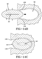
- FIG. 14A is an enlarged view and 14B is a detailed view showing the tube 42 compressed and inserted into the groove 56.
- FIG. 14C is a detailed view showing the tube 42 fully inserted into the groove 56.
- the tube 42 may be generally elliptical in cross-section inserting into a like-configured groove 56.
- the groove 56 may have a narrow entryway formed between opposite parallel surfaces 148, 150.
- the tube 42 is configured having an external geometry and passageway configuration with dimensions within the preferred ranges specified as follows:
- FIGS. 15A through 15C show another tube 42 and groove 56 configuration.
- FIG. 15A is an enlarged view and
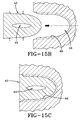
- FIG. 15B is a detailed view showing the tube 42 compressed and inserted into the groove 56.
- FIG. 15C is a detailed view showing the tube 42 fully inserted into the groove 56.
- the tube 42 may be generally have a parabolic cross-section for inserting into a like-configured groove 56.
- the groove 56 may have an entryway sized to closely accept the tube 42 therein.
- the ridges 66 may engage the tube 42 once inserted into the groove 56.
- the tube 42 has an external geometry and passageway configuration with dimensions within the preferred ranges specified as follows:
- the present invention may comprise a bi-directionally peristaltic pump assembly 14 for air maintenance of a tire 12.
- the circular air tube 42 may flatten, segment by segment, and close in the tire footprint 100.
- the air inlet device 68 may include an outer filter sleeve 92 formed of porous cellular material and thereby render the air inlet device 68 self-cleaning.
- the outlet device 70 may employ a valve unit (see US-A-2011-0272073 ).
- the peristaltic pump assembly 14 may pump air through rotation of the tire 12 in either direction, one half of a revolution pumping air to the tire cavity 40 and the other half of a revolution pumping air back out of the inlet device 68.
- the peristaltic pump assembly 14 may be used with a secondary tire pressure monitoring system (TPMS) (not shown) that may serve as a system fault detector.
- TPMS secondary tire pressure monitoring system
- the TPMS may be used to detect any fault in the self-inflation system of the tire assembly 10 and alert the user of such a condition.
- the tire air maintenance system 10 may further incorporate a variable pressure pump groove 56 with one or more inwardly directed ridges or ribs 66 engaging and compressing a segment of the air tube 42 opposite such rib(s).
- the pitch or frequency of the ribs may increase toward the outlet device 70 for gradually reducing air volume within the passageway 43 by compressing the tube 42.
- the reduction in air volume may increase air pressure within the passageway 43 and thereby facilitate a more efficient air flow from the tube 42 into the tire cavity 40.
- the increase in tube pressure may be achieved by engagement by the ribs 66 of the groove 56 and the tube 42 having uniform dimensions along the tube length.
- the tube 42 may thus be made of uniform dimension and of relatively smaller size without compromising the flow pressure of air to the tire cavity 40 for maintaining air pressure.
- the pitch and amplitude of the ridges 66 may both be varied to better achieve the desired pressure increase within the passageway 43.
- Structures in a pneumatic tire may require the embedding of certain rigid parts, functional devices, and/or connectors into adhering onto the rubber of the tire.
- the structures 14, 42, 68, 70, 101, 202, etc. of the example air maintenance tire 10 described above may require embedding/adherence.
- Such structures 14, 42, 68, 70, 101, 202, etc. typically encounter high stresses during operating conditions of the tire 10.
- strong bonding of such structures 14, 42, 68, 70, 101, 202, etc. is desired since a bond break at the structure's 14, 42, 68, 70, 101, 202, etc. surface will likely lead to destruction of the assembly 14 and/or the integrity of the tire 10 as a whole.
- a polyamide elbow-like structure 70 may be bonded to a tire 10 in order to define a built-in tube-like cavity ( FIG. 3C ).
- This structure 70 may thereby allow rerouting of pressurized air to a pump assembly 14 and from there, into a tire cavity 40, as well as to make a connection to the outside for providing fresh unpressurized air to the pump assembly.
- the tire 12 and the self inflating tire technology (SIT/AMT) described above also uses a filter 200 in accordance with the present invention as part of such a pneumatic tire 12 for filtering air prior to its entry into the tire cavity 40.
- the filter 200 should have sufficiently high air permeation, as well as acceptable cost, chemical and mechanical durability, the ability to detain water, and/or avoid complexity.
- the filter 200 is constructed of a porous plastic.
- porous plastics e.g., polypropylene, polyethylene, teflon, etc.
- These porous plastics combine flexibility in shape, chemical durability, potential to detain water, low complexity, and low manufacturing cost to demonstrate a novel and extremely useful filter material for SIT/AMT tires, such as the pneumatic tire 12.
- the properties of air permeation, chemical durability, and water separation potential may be reduced to a mere material property relating to pore size distribution and type of polymer.
- screws may be manufactured of porous plastics thereby not requiring embedding the material into a metal or plastic frame material (e.g., threads mechanically secure filter 200 to the pneumatic tire 12). This may reduce complexity to a lowest level possible and accordingly minimize manufacturing cost of the filter 200 and/or filter assembly.
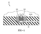
- a grub screw 200 of a porous plastic material may be threaded into a connector 202 that is embedded in the sidewall 30, 32 of a pneumatic self inflating tire 12 thereby filtering an air flow between the atmosphere, through the filter 200, into the tire cavity 40.
- a filter 200 may also hold up well as part of a pneumatic tire 12 rotating and under load. Further, such a filter 200 comprises an improvement over conventional woven metal filters in corrosion is eliminated, ability to detain water is enhanced, and cost and complexity are reduced.
- an air filter 1700 in accordance with the present invention may be used in an AMT, as described above.
- the air filter 1700 allows water droplets to run over a membrane external surface 1711, and thus clean it, without blocking an inlet to the AMT system.
- the air filter 1700 includes a filter support housing 1720 defining a membrane seat 1721 for receiving an air membrane 1710 used for air filtration.
- the filter support housing 1720 preferably also includes an air outlet 1723 for supplying air to the pump system described above.
- multiple membranes 1710 may be stacked in order to utilize differing porosities of different membrane materials.
- a membrane external surface 1711 is constructed of a hydrophobic material for avoiding all liquid adhesion to it. The liquid flow on the membrane surface 1711 thus removes particles deposited on the membrane surface, thereby cleaning it.
- the hydrophobic material is preferably polytetrafluoroethylene (PTFE), which can be integrated into the external surface 1711 of the membrane 1710 or used to coat or spray the external surface of the membrane.
- PTFE polytetrafluoroethylene
- a filter lock member 1730 may clamp the membrane 1710 and keep it secured to the filter support housing 1720.
- the filter lock member 1730 may include barbs, threads, and/or clips.
- the filter lock member 1730 may also include air inlets 1733 for supplying the pump system described above.
- the external surface 1731 of the lock member 1730 is preferably treated with a hydrophilic material to capture water and/or other liquid for cleaning the membrane surface 1711.
- channels 1733 leading toward the membrane 1710 may be coated or sprayed with the hydrophobic material to facilitate liquid flow through the air filter 1700.
- the air filter 1700 may further include an O-ring 1740 for sealing the filter support housing 1720 to the tire 12.
Landscapes
- Engineering & Computer Science (AREA)
- Mechanical Engineering (AREA)
- Tires In General (AREA)
Abstract
Description
- The present invention relates generally to filtering air for a pneumatic tire and, more specifically, to filtering air into a pumping assembly for a pneumatic tire.
- Normal air diffusion reduces tire pressure over time. The natural state of tires is under inflated. Accordingly, drivers must repeatedly act to maintain tire pressures or they will see reduced fuel economy, tire life and reduced vehicle braking and handling performance. Tire Pressure Monitoring Systems have been proposed to warn drivers when tire pressure is significantly low. Such systems, however, remain dependant upon the driver taking remedial action when warned to re-inflate a tire to recommended pressure. It is a desirable, therefore, to incorporate an air maintenance feature within a tire that will maintain air pressure within the tire in order to compensate for any reduction in tire pressure over time without the need for driver intervention. A self-inflating tire comprising a filter is known for instance from
US-A-2012/0060993 - The invention relates to a tire in accordance with
claim 1 and to a method in accordance withclaim 13. - Dependent claims refer to preferred embodiments of the invention.
- A pneumatic tire in accordance with a preferred aspect of the present invention includes a pneumatic cavity and a filter disposed between the pneumatic cavity and atmosphere. The filter is constructed of a hydrophobic material for avoiding all liquid adhesion. First and second sidewalls extend respectively from first and second tire bead regions to a tire tread region. The first sidewall has at least one bending region operatively bending when radially within a rolling tire footprint. A sidewall groove is defined by groove walls positioned within the bending region of the first tire sidewall. The sidewall groove deforms segment by segment between a non-deformed state and a deformed, constricted state in response to bending of the bending region of the first sidewall while radially within the rolling tire footprint. An air passageway is defined by the sidewall groove and deforms segment by segment between an expanded condition and an at least partially collapsed condition in response to respective segment by segment deformation of the sidewall groove when radially within the rolling tire footprint.
- According to another preferred aspect of the invention, the filter includes a filter support housing defining a membrane seat for receiving an air membrane for air filtration.
- According to another preferred aspect of the invention, the filter support housing includes an air outlet for supplying air to the air passageway.
- According to another preferred aspect of the invention, the air membrane comprises polytetrafluoroethylene.
- According to another preferred aspect of the invention, the filter includes a hydrophilic material for capturing liquid to clean a membrane surface of the air membrane.
- According to another preferred aspect of the invention, the air membrane comprises multiple membranes stacked on each other in order to utilize differing porosities of different membrane materials.
- According to another preferred aspect of the invention, the filter includes an O-ring for sealing the filter support housing to the tire.
- According to another preferred aspect of the invention, the filter includes a filter lock member for securing the air membrane to the filter support housing.
- According to another preferred aspect of the invention, the filter lock member includes air inlets for supplying ambient air to the air passageway.
- According to another preferred aspect of the invention, the air inlets are coated with the hydrophobic material to facilitate liquid flow through the filter.
- The method in accordance with a preferred aspect of the invention maintains air pressure in a pneumatic tire cavity. The method includes the steps of placing a filter between the pneumatic cavity and atmosphere, the filter being constructed of a hydrophobic material for avoiding liquid adhesion and deforming an air passageway segment by segment between an expanded condition and an at least partially collapsed condition in response to respective segment by segment deformation of a sidewall groove when radially within a rolling tire footprint.
- According to another preferred aspect of the invention, a further step includes securing an air membrane to a membrane seat of a filter support housing.
- According to another preferred aspect of the invention, a further step includes supplying air to the air passageway.
- According to another preferred aspect of the invention, the air membrane includes polytetrafluoroethylene.
- According to another preferred aspect of the invention, a further step includes capturing liquid by a hydrophilic material.
- According to another preferred aspect of the invention, a further step includes stacking multiple membranes in order to utilize differing porosities of different membrane materials for air filtration.
- According to another preferred aspect of the invention, a further step includes sealing the filter support housing to the tire with an O-ring.
- According to another preferred aspect of the invention, a further step includes securing the air membrane to the filter support housing by a filter lock member.
- According to another preferred aspect of the invention, a further step includes supplying ambient air to the air passageway by an air inlet of the filter lock member.
- According to another preferred aspect of the invention, a further step includes coating the air inlet with the hydrophobic material to facilitate liquid flow through the filter.
- "Axial" and "axially" means lines or directions that are parallel to the axis of rotation of the tire.
- "Circumferential" means lines or directions extending along the perimeter of the surface of the annular tread perpendicular to the axial direction.
- "Footprint" means the contact patch or area of contact of the tire tread with a flat surface at zero speed and under normal load and pressure.
- "Hydrophilic material" means a material that tends to interact with, be dissolved by, and/or is attracted to water or liquid. Hydrophilic substances (e.g., salts, sugars, etc.) may seem to attract water out of the air.
- "Hydrophobic material" means a material that seemingly repels water or liquid. Strictly speaking, there is no repulsive force involved; it is an absence of attraction. Examples of hydrophobic molecules and materials include alkanes, oils, fats, and greasy substances, in general.
- "Lateral" means an axial direction.
- "Peristaltic" means operating by means of wave-like contractions that propel contained matter, such as air, along tubular pathways.
- "Radial" and "radially" means directions radially toward or away from the axis of rotation of the tire.
- The present invention will be described by way of example and with reference to the accompanying drawings, in which:
- Fig-1 is a schematic view of an example filter.
- Fig-2 is a side view of the example tire/tube assembly.
- Fig-3A-3C show details of an example outlet connector.
- Fig-4A-4E show details of an example inlet (filter) connector.
- Fig-5A is a side view of an example tire rotating with air movement (84) to cavity.
- Fig-5B is a side view of the example tire rotating with air flushing out filter.
- Fig-6A is a section view taken from Fig-5A.
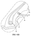
- Fig-6B is an enlarged detail of tube area taken from Fig-6A, sidewall in non-compressed state.
- Fig-7A is a section view taken from Fig-5A.
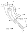
- Fig-7B is an enlarged detail of tube area taken from Fig-7A, sidewall in compressed state.
- Fig-8A is an enlarged detail of an example tube & groove detail taken from Fig-2.
- Fig-8B is a detail showing an example tube compressed and being inserted into the groove.
- Fig-8C is a detail showing an example tube fully inserted into the groove at a ribbed area of the groove.
- Fig-8D is an exploded fragmented view of tube being inserted into a ribbed groove.
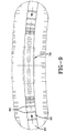
- Fig-9 is an enlarged detail taken from Fig-2 showing an example rib profile area located on both sides of the outlet to a cavity connector.
- Fig-10A is an enlarged detail of the groove with the example rib profile.
- Fig-10B is an enlarged detail of tube pressed into the example rib profile.
- Fig-11 is an enlarged detail taken from Fig-2 showing another example rib profile area elocated on both sides of the outlet to a cavity connector.
- Fig-12A is an enlarged detail of the groove with the other example rib profile.
- Fig-12B is an enlarged detail of the tube pressed into the other example rib profile.
- Fig-13A is an enlarged view of another example tube & groove detail.
- Fig-13B is a detail showing tube from Fig-13A being compressed and inserted into the groove.
- Fig-13C is a detail showing the tube from Fig-13A fully inserted into the groove.
- Fig-14A is an enlarged view of a third example tube & groove detail.
- Fig-14B is a detail showing tube from Fig-14A being compressed and inserted into the groove.
- Fig-14C is a detail showing the tube from Fig-14A fully inserted into the groove.
- Fig-15A is an enlarged view of a fourth example tube & groove detail.
- Fig-15B is a detail showing tube from Fig-15A being compressed and inserted into the groove.
- Fig-15C is a detail showing the tube from Fig-15A fully inserted into the groove.
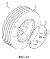
- Fig-16 is an isometric exploded view of an example tire and tube assembly.
- Fig-17A and 17B are schematic views of an example filter in accordance with the present invention.
- Fig-18A and 18B are schematic exploded views of the filter of
FIGS. 17A and 17B . - Referring to
FIGS. 16 ,2 , and6A , anexample tire assembly 10 is shown comprising atire 12 and aperistaltic pump assembly 14. The tire is mounted on atire rim 16. Thetire 12 preferably mounts in conventional fashion to a pair ofrim mounting surfaces outer rim flanges flange end 26. Arim body 28 may support thetire assembly 10 as shown. Thetire 12 is preferably of a conventional construction, having a pair ofsidewalls opposite bead areas tire tread region 38. Thetire 12 and rim 16 enclose atire cavity 40. - As seen from
FIGS. 2 and3A, 3B, 3C ,6B and8A , the exampleperistaltic pump assembly 14 preferably includes a preferablyannular air tube 42 that encloses a preferablyannular passageway 43. Thetube 42 is formed of a resilient, flexible material such as plastic or rubber compounds that are capable of withstanding repeated deformation cycles of a flattened condition subject to external force and, upon removal of such force, returned to an original condition generally circular in cross-section. Thetube 42 has a diameter sufficient to operatively pass a volume of air for purposes described herein and allowing a positioning of the tube in an operable location within thetire assembly 10 as will be described below. In the example configuration shown, thetube 42 is of an elongate, generally elliptical shape in cross-section, having opposite tube sidewalls 44, 46 extending from a flat (closed) trailingtube end 48 to a radiussed (open) leadingtube end 50. Thetube 42 may have a longitudinal outwardly projecting pair oflocking detent ribs 52 of generally semi-circular cross-section and each rib extending along outward surfaces of thesidewalls - As referenced in
FIG 8A , thetube 42 may have a length L1 within a range of 3.65 mm to 3.80 mm; a width of D1 within a range of 2.2 mm to 3.8 mm; a trailing end width of D3 within a range of 0.8 mm to 1.0 mm. The protrudingdetent ribs tube end 48. The leadingend 50 of thetube 42 may have a radius R1 within a range of 1.1 mm to 1.9 mm. Theair passageway 43 within thetube 42 may likewise be generally elliptical with a length L2 within a range of 2.2 mm to 2.3 mm; and a width D2 within a range of 0.5 mm to 0.9 mm. - The
tube 42 is preferably profiled and geometrically configured for insertion into agroove 56. Thegroove 56 may have an elongate, generally elliptical configuration with a length L1 within a range of 3.65 mm to 3.80 mm complementary to the elliptical shape of thetube 42. Thegroove 56 may include a restrictednarrower entryway 58 having a nominal cross-sectional width D3 within a range of 0.8 mm to 1.0 mm. A pair of groove-rib receivingaxial detent channels groove 56 for corresponding receipt of thetube locking ribs channels groove entryway 58.Detent channels detent groove portion 64 may be formed with a radius of curvature R1 within a range of 1.1 mm to 1.9 mm and a cross-sectional nominal width D1 within a range of 2.2 mm to 3.8 mm. - As best seen from
FIGS. 8D ,9 ,10A and 10B , thetire 12 may further form one ormore compression ribs 66 extending the circumference of, and projecting into, thegroove 56. Theribs 66 may form a pattern of ribs of prescribed pitch, frequency, and location, as described below. For the purpose of explanation, seven compression ribs may be referred to generally by numeral 66 in the first rib profile pattern shown, and specifically by the rib designations D0 through D6. The ribs D0 through D6 may be formed in a sequence and pitch pattern in order to optimize the pumping of air through thetube passageway 43. Theribs 66 may each have a unique and predetermined height and placement within the pattern and, as shown inFIG. 8D , project outward into thegroove 56 at a radius R3 (FIG. 8A ) within a range of 0.95 mm to 1.60 mm. - With reference to
FIGS. 16 ,2 ,3A through 3C , and4A through E , theperistaltic pump assembly 14 includes aninlet device 68 and anoutlet device 70 preferably spaced apart approximately 180 degrees at respective locations along theair passageway 43 or the preferablycircumferential air tube 42. - The
example outlet device 70 has a T-shaped configuration in whichconduits tire cavity 40. Anoutlet device housing 76 preferably containsconduit arms respective conduits conduit arms external coupling ribs air tube 42 in the assembled condition. Thehousing 76 is preferably formed having an external geometry that complements thegroove 56 and includes aflat end 86, a radiused generally oblongbody 88, and outwardly projectinglongitudinal detent ribs 90. Thehousing 76 may thus be capable of close receipt into thegroove 56 at its intended location with theribs 90 registering within thegroove 56 as represented inFIG. 8A . - The
inlet device 68, as seen inFIGS. 12 ,4A through 4E , preferably includes an elongateoutward sleeve body 94 joining an elongateinward sleeve body 96 at anarrow sleeve neck 98. The outward sleeve body is preferably generally triangular in section. Theinward sleeve body 96 has an oblong external geometry complementary to thegroove 56 and includes a pair ofdetent ribs 100 extending longitudinally along the inward sleeve body. An elongateair entry tube 101 is positioned within theinward sleeve body 96 and includes opposite tube ends 102 and a pattern ofentry apertures 104 extending into a central tube passageway.External ribs air tube 42 opposite theoutlet device 70. - As shown in
FIGS. 6A ,6B ,7A ,7B ,8A through D , thepump assembly 14 may comprise theair tube 42 and inlet andoutlet devices groove 56. Thegroove 56 is preferably located at a lower sidewall region of thetire 12 that, when the tire is mounted to therim 16, positions theair tube 42 above the rim flange ends 26.FIG. 8B shows theair tube 42 diametrically squeezed and collapsed to accommodate insertion into thegroove 56. Upon full insertion, as shown inFIG. 8C , theribs groove channels outer end 48 of thetube 42 may be generally coplanar with the outer surface of the sidewall of the tire. Once fully inserted, theair passageway 43 of thetube 42 may elastically restore itself into an open condition to allow the flow of air along the tube during operation of the pump. - Referring to
FIGS. 16 ,2 ,5A ,5B ,6A ,6B ,7A ,7B ,8A through 8D , theinlet device 68 and theoutlet device 70 are preferably positioned within the circumference of thecircular air tube 42 generally 180 degrees apart. Thetire 12 with thetube 42 positioned withingroove 56 rotates in a direction ofrotation 110, causing afootprint 120 to be formed against theground surface 118. Acompressive force 124 is directed into thetire 12 from thefootprint 120 and acts to flatten a segment of theair tube passageway 43 opposite thefootprint 120, as shown atnumeral 122. Flattening of a segment of thepassageway 43 forces air from the segment along thetube passageway 43 in the direction shown byarrow 116, toward theoutlet device 70. - As the
tire 12 continues to rotate in thedirection 110 along theground surface 118, thetube 42 is sequentially flattened or squeezed opposite the tire footprint, segment by segment, in a direction opposite to thedirection 110. A sequential flattening of thetube passageway 43, segment by segment, may cause evacuated air from the flattened segments to be pumped in thedirection 116 withintube passageway 43 toward theoutlet device 70. Air flows through theoutlet device 70 and to thetire cavity 40, as shown at 130. At 130, air exiting theoutlet device 70 is routed to thetire cavity 40 and serves to re-inflate thetire 12 to a desired pressure level. A valve system to regulate the flow of air to thecavity 40, when the air pressure within the cavity falls to a prescribed level, is shown and described inUS-A-2011/0272073 , which is incorporated herein by reference. - With the
tire 12 rotating indirection 110, flattened tube segments may be sequentially refilled by air flowing into theinlet device 68 in thedirection 114, as shown byFIG. 5A . The inflow of air into theinlet device 68, and then into thetube passageway 43, may continue until theoutlet device 70, rotating in acounterclockwise direction 110, passes thetire footprint 120.FIG. 5B shows the orientation of theperistaltic pump assembly 14 in such a position. Thetube 42 may continue to be sequentially flattened, segment by segment, opposite thetire footprint 120 by acompressive force 124. Air may be pumped in theclockwise direction 116 to theinlet device 68 and evacuated or exhausted external to thetire 12. Passage of exhaust air, as shown at 128, from theinlet device 68 may occur through afilter sleeve 92 exemplarily formed of a cellular or porous material or composite. Flow of air through thefilter sleeve 92 and into thetube 101 may thus cleanse debris or particulates. In the exhaust or reverse flow ofair direction 128, thefilter sleeve 92 may be cleansed of trapped accumulated debris or particles within the porous medium. With the evacuation of pumped air out of theinlet device 68, theoutlet device 70 may be in a closed position preventing air flow to thetire cavity 40. When thetire 12 rotates further incounterclockwise direction 110 until theinlet device 70 passes the tire footprint 120 (as shown inFIG. 5A ), the airflow may resume to the outlet device and cause the pumped air to flow out and into thetire cavity 40. Air pressure within thetire cavity 40 may thus be maintained at a desired level. -
FIG. 5B illustrates that thetube 42 is flattened, segment by segment, as thetire 12 rotates indirection 110. A flattenedsegment 134 moves counterclockwise as it is rotated away from thetire footprint 120 while anadjacent segment 132 moves opposite the tire footprint and is flattened. Accordingly, the progression of squeezed or flattened or closed tube segments may be move air toward the outlet device 70 (FIG. 5A ) or the inlet device 68 (FIG. 5B ) depending on the rotational position of thetire 12 relative to such devices. As each segment is moved by tire rotation away from thefootprint 120, the compression forces within thetire 12 from the footprint region may be eliminated and the segment may resiliently reconfigure into an unflattened or open condition as the segment refills with air from thepassageway 43.FIGS. 7A and7B show a segment of thetube 42 in the flattened condition whileFIGS. 6A and6B show the segment in an expanded, unflat or open configuration prior to, and after, moving away from a location opposite thetire footprint 120. In the original non-flattened configuration, segments of thetube 42 may resume the exemplary oblong generally elliptical shape. - The above-described cycle may repeat for each tire revolution, with half of each rotation resulting in pumped air moving to the
tire cavity 40 and half of each rotation resulting in pumped air moving back out thefilter sleeve 92 of theinlet device 68 for self-cleaning the filter. It may be appreciated that while the direction ofrotation 110 of thetire 12 is as shown inFIGS. 5A and5B is counterclockwise, thesubject tire assembly 10 and itsperistaltic pump assembly 14 may function in a like manner in a reverse (clockwise) direction of rotation as well. Theperistaltic pump assembly 14 may accordingly be bi-directional and equally functional with thetire 12 and vehicle moving in a forward or reverse direction of rotation and forward or reverse direction of the vehicle. - The air tube/
pump assembly 14 may be as shown inFIGS.5A ,5B ,6A ,6B ,7A and7B . Thetube 42 may be located within thegroove 56 in a lower region of thesidewall 30 of thetire 12. Thepassageway 43 of thetube 42 may close by compression strain bending of thesidewall groove 56 within a rollingtire footprint 120, as explained above. The location of thetube 42 in thesidewall 30 may provide freedom of placement thereby avoiding contact between thetube 42 and therim 16. Higher placement of thetube 42 in thesidewall groove 56 may use high deformation characteristics of this region of the sidewall as it passes through thetire footprint 120 to close thetube 42. - The configuration and operation of the grooved sidewalls, and in particular the variable pressure pump compression of the
tube 42 by operation of ridges orcompression ribs 66 within thegroove 56 is shown inFIGS. 8A-8D ,9 ,10A and 10B . The ridges or ribs are indicated bynumeral 66 and individually as D0 through D6. Thegroove 56 may be uniform width circumferentially along the side of thetire 12 with the molded ridges D0 through D6 formed to project into thegroove 56 in a preselected sequence, pattern, or array. The ridges D0 through D6 may retain thetube 42 in a predetermined orientation within thegroove 56 and also may apply a variable sequential constriction force to the tube. - The uniformly dimensioned
pump tube 42 may be positioned within thegroove 56 as explained above - a procedure initiated by mechanically spreading the entryway D3 of thegroove 56 apart. Thetube 42 may then be inserted into the enlarged opening of thegroove 56. The opening of thegroove 56 may thereafter be released to return to close into the original spacing D3 and thereby capture thetube 42 inside the groove. Thelongitudinal locking ribs longitudinal grooves ribs tube 42 inside thegroove 56 and prevent ejection of the tube from thegroove 56 during tire operation/rotation. - Alternatively, the
tube 42 may be press inserted into thegroove 56. Thetube 42, being of uniform width dimensions and geometry, may be manufactured in large quantities. Moreover, a uniform dimensionedpump tube 42 may reduce overall assembly time, material cost, and non-uniformity of tube inventory. From a reliability perspective, this results in less chance for scrap. - The circumferential ridges D0 through D6 projecting into the
groove 56 may increase in frequency (number of ridges per axial groove unit of length) toward the inlet passage of thetube 42, represented by theoutlet device 70. Each of the ridges D0 through D6 may have a common radius dimension R4 within a range of 0.15 mm to 0.30 mm. The spacing between ridges D0 and D1 may be largest, the spacing between D1 and D2 the next largest, and so on until the spacing between ridges D5 and D6 is nominally eliminated. While seven ridges are shown, more or fewer ridges may be deployed at various frequency along thegroove 56. - The projection of the ridges into the
groove 56 by radius R4 may serve a twofold purpose. First, the ridges D0 through D6 may engage thetube 42 and prevent the tube from migrating, or "walking", along thegroove 56 during tire operation/rotation from the intended location of the tube. Secondly, the ridges D0 through D6 may compress the segment of thetube 42 opposite each ridge to a greater extent as thetire 12 rotates through its rotary pumping cycle, as explained above. The flexing of the sidewall may manifest a compression force through each ridge D0 through D6 and may constrict the tube segment opposite such ridge to a greater extent than otherwise would occur in tube segments opposite non-ridged portions of thegroove 56. As seen inFIGS. 10A and 10B , as the frequency of the ridges increases in the direction of air flow, a pinching of thetube passageway 43 may progressively occur until the passageway constricts to the size shown atnumeral 136, gradually reducing the air volume and increasing the pressure. As a result, with the presence of the ridges, thegroove 56 may provide variable pumping pressure within thetube 42 configured to have a uniform dimension therealong. As such, thesidewall groove 56 may be a variable pressure pump groove functioning to apply a variable pressure to atube 42 situated within the groove. It will be appreciated that the degree of pumping pressure variation may be determined by the pitch or ridge frequency within thegroove 56 and the amplitude of the ridges deployed relative to the diametric dimensions of thetube passageway 43. The greater the ridge amplitude relative to the diameter, the more air volume may be reduced in the tube segment opposite the ridge and pressure increased, and vice versa.FIG. 9 depicts the attachment of thetube 42 to theoutlet device 70 and the direction of air flow on both sides into outlet device. -
FIG. 11 shows a second alternative rib profile area located on both sides of the outlet to theoutlet device 70.FIG. 12A shows an enlarged detail of thegroove 56 with the alternative second rib profile andFIG. 12B shows an enlarged detail of thetube 42 pressed into the second rib profile. With reference toFIGS. 11 ,12A, 12B , the ridges, or ribs, D0 through D6 in this alternative may have a frequency pattern similar to that described above in reference toFIGS. 10A, 10B , but with each rib having a unique respective amplitude as well. Each of the ribs D0 through D6 may generally have a semi-circular cross-section with a respective radius of curvature R1 through R7, respectively. The radii of curvatures of the ridges/ D0 through D6 may be within the exemplary range: Δ = 0.020 mm to 0.036 mm. - The number of ridges D0 through D6 and respective radii of each ridge may be constructed outside the above ranges to suit other dimensions or applications. The increasing radius of curvature in the direction of air flow may result in the ridges D0 through D6 projecting at an increasing amplitude and, to an increasing extent, into the
passageway 43 toward theoutlet device 70. As such, thepassageway 43 may constrict to anarrower region 138 toward theoutlet device 70 and cause a correspondingly greater increase in air pressure from a reduction in air volume. The benefit of such a configuration is that thetube 42 may be constructed smaller than otherwise necessary in order to achieve a desired air flow pressure along thepassageway 43 and into thetire cavity 40 from theoutlet device 70. A smallersized tube 42 may be economically and functionally desirable in allowing asmaller groove 56 within thetire 12 to be used, thereby resulting a minimal structural discontinuity in the tire sidewall. -
FIGS. 13A through 13C show anothertube 42 andgroove 56 detail in which thedetent ribs 90 ofFIG. 8A through 8C are eliminated as a result of rib and groove modification. Thistube 42 may have an external geometry and passageway configuration with indicated dimensions within preferred ranges specified as follows: - D1= 2.2 to 3.8 mm;
- D2= 0.5 to 0.9 mm;
- D3= 0.8 to 1.0 mm;
- R4= 0.15 to 0.30 mm;
- L1= 3.65 to 3.8 mm;
- L2= 2.2 to 2.3 mm;
- L3=1.8 to 2.0 mm.
- The above ranges may be modified to suit a particular dimensional preference, tire geometry, or tire application. The external configuration of the
tube 42 may includebeveled surfaces end surface 48; parallel and opposite straightintermediate surfaces forward surface 146, adjoining theintermediate surfaces FIGS. 13B and 13C , thetube 42 may be compressed for press insertion into thegroove 56 and, upon full insertion, expand. The constricted opening of thegroove 56 at the sidewall surface may retain thetube 42 securely within thegroove 56. -
FIGS. 14A through 14C show anothertube 42 andgroove 56 configuration.FIG. 14A is an enlarged view and 14B is a detailed view showing thetube 42 compressed and inserted into thegroove 56.FIG. 14C is a detailed view showing thetube 42 fully inserted into thegroove 56. Thetube 42 may be generally elliptical in cross-section inserting into a like-configuredgroove 56. Thegroove 56 may have a narrow entryway formed between oppositeparallel surfaces FIGS. 14A through 14C , thetube 42 is configured having an external geometry and passageway configuration with dimensions within the preferred ranges specified as follows: - D1= 2.2 to 3.8 mm;
- D2= 0.5 to 0.9 mm;
- D3=0.8 to 1.0 mm;
- R4= 0.15 to 0.30 mm;
- L1= 3.65 to 3.8 mm;
- L2= 2.2 to 2.3 mm;
- L3= 1.8 to 2.0 mm.
- The above ranges may be modified to suit a particular dimensional preference, tire geometry, or tire application.
FIGS. 15A through 15C show anothertube 42 andgroove 56 configuration.FIG. 15A is an enlarged view andFIG. 15B is a detailed view showing thetube 42 compressed and inserted into thegroove 56.FIG. 15C is a detailed view showing thetube 42 fully inserted into thegroove 56. Thetube 42 may be generally have a parabolic cross-section for inserting into a like-configuredgroove 56. Thegroove 56 may have an entryway sized to closely accept thetube 42 therein. Theridges 66 may engage thetube 42 once inserted into thegroove 56. InFIGS. 15A through 15C , thetube 42 has an external geometry and passageway configuration with dimensions within the preferred ranges specified as follows: - D1= 2.2 to 3.8 mm;
- D2= 0.5 to 0.9 mm;
- D3= 2.5 to 4.1 mm;
- L1= 3.65 to 3.8 mm;
- L2= 2.2 to 2.3 mm;
- L3= 1.8 to 2.0 mm.
- The above ranges may be modified to suit a particular dimensional preference, tire geometry, or tire application if desired.
- From the forgoing, it will be appreciated that the present invention may comprise a bi-directionally
peristaltic pump assembly 14 for air maintenance of atire 12. Thecircular air tube 42 may flatten, segment by segment, and close in thetire footprint 100. Theair inlet device 68 may include anouter filter sleeve 92 formed of porous cellular material and thereby render theair inlet device 68 self-cleaning. Theoutlet device 70 may employ a valve unit (seeUS-A-2011-0272073 ). Theperistaltic pump assembly 14 may pump air through rotation of thetire 12 in either direction, one half of a revolution pumping air to thetire cavity 40 and the other half of a revolution pumping air back out of theinlet device 68. Theperistaltic pump assembly 14 may be used with a secondary tire pressure monitoring system (TPMS) (not shown) that may serve as a system fault detector. The TPMS may be used to detect any fault in the self-inflation system of thetire assembly 10 and alert the user of such a condition. - The tire
air maintenance system 10 may further incorporate a variablepressure pump groove 56 with one or more inwardly directed ridges orribs 66 engaging and compressing a segment of theair tube 42 opposite such rib(s). The pitch or frequency of the ribs may increase toward theoutlet device 70 for gradually reducing air volume within thepassageway 43 by compressing thetube 42. The reduction in air volume may increase air pressure within thepassageway 43 and thereby facilitate a more efficient air flow from thetube 42 into thetire cavity 40. The increase in tube pressure may be achieved by engagement by theribs 66 of thegroove 56 and thetube 42 having uniform dimensions along the tube length. Thetube 42 may thus be made of uniform dimension and of relatively smaller size without compromising the flow pressure of air to thetire cavity 40 for maintaining air pressure. The pitch and amplitude of theridges 66 may both be varied to better achieve the desired pressure increase within thepassageway 43. - Structures in a pneumatic tire may require the embedding of certain rigid parts, functional devices, and/or connectors into adhering onto the rubber of the tire. For example, the
structures air maintenance tire 10 described above may require embedding/adherence.Such structures tire 10. Thus, strong bonding ofsuch structures assembly 14 and/or the integrity of thetire 10 as a whole. - For example, a polyamide elbow-
like structure 70 may be bonded to atire 10 in order to define a built-in tube-like cavity (FIG. 3C ). Thisstructure 70 may thereby allow rerouting of pressurized air to apump assembly 14 and from there, into atire cavity 40, as well as to make a connection to the outside for providing fresh unpressurized air to the pump assembly. - The
tire 12 and the self inflating tire technology (SIT/AMT) described above also uses afilter 200 in accordance with the present invention as part of such apneumatic tire 12 for filtering air prior to its entry into thetire cavity 40. - The
filter 200 should have sufficiently high air permeation, as well as acceptable cost, chemical and mechanical durability, the ability to detain water, and/or avoid complexity. Prefereably, thefilter 200 is constructed of a porous plastic. - Conventionally, porous plastics (e.g., polypropylene, polyethylene, teflon, etc.) are offered as air filter material for several applications. These porous plastics combine flexibility in shape, chemical durability, potential to detain water, low complexity, and low manufacturing cost to demonstrate a novel and extremely useful filter material for SIT/AMT tires, such as the
pneumatic tire 12. The properties of air permeation, chemical durability, and water separation potential may be reduced to a mere material property relating to pore size distribution and type of polymer. As an example, screws may be manufactured of porous plastics thereby not requiring embedding the material into a metal or plastic frame material (e.g., threads mechanicallysecure filter 200 to the pneumatic tire 12). This may reduce complexity to a lowest level possible and accordingly minimize manufacturing cost of thefilter 200 and/or filter assembly. - As shown in
FIG. 1 , agrub screw 200 of a porous plastic material may be threaded into aconnector 202 that is embedded in thesidewall self inflating tire 12 thereby filtering an air flow between the atmosphere, through thefilter 200, into thetire cavity 40. Such afilter 200 may also hold up well as part of apneumatic tire 12 rotating and under load. Further, such afilter 200 comprises an improvement over conventional woven metal filters in corrosion is eliminated, ability to detain water is enhanced, and cost and complexity are reduced. - As shown in
FIGS. 17A, 17B ,18A,18B , anair filter 1700 in accordance with the present invention may be used in an AMT, as described above. Theair filter 1700 allows water droplets to run over a membraneexternal surface 1711, and thus clean it, without blocking an inlet to the AMT system. - The
air filter 1700 includes afilter support housing 1720 defining amembrane seat 1721 for receiving anair membrane 1710 used for air filtration. - The
filter support housing 1720 preferably also includes anair outlet 1723 for supplying air to the pump system described above. - Alternatively,
multiple membranes 1710 may be stacked in order to utilize differing porosities of different membrane materials. - To produce a self-cleaning effect, a membrane
external surface 1711 is constructed of a hydrophobic material for avoiding all liquid adhesion to it. The liquid flow on themembrane surface 1711 thus removes particles deposited on the membrane surface, thereby cleaning it. - The hydrophobic material is preferably polytetrafluoroethylene (PTFE), which can be integrated into the
external surface 1711 of themembrane 1710 or used to coat or spray the external surface of the membrane. - A
filter lock member 1730 may clamp themembrane 1710 and keep it secured to thefilter support housing 1720. Thefilter lock member 1730 may include barbs, threads, and/or clips. Thefilter lock member 1730 may also includeair inlets 1733 for supplying the pump system described above. - The
external surface 1731 of thelock member 1730 is preferably treated with a hydrophilic material to capture water and/or other liquid for cleaning themembrane surface 1711. Conversely,channels 1733 leading toward themembrane 1710 may be coated or sprayed with the hydrophobic material to facilitate liquid flow through theair filter 1700. Theair filter 1700 may further include an O-ring 1740 for sealing thefilter support housing 1720 to thetire 12.
Claims (15)
- A pneumatic tire (12), preferably a self-inflating pneumatic tire, having a pneumatic cavity (40), an air passageway (43) between the pneumatic cavity (40) and atmosphere, and a filter (1700) disposed between the pneumatic cavity (40) and atmosphere, characterized in that the filter (1700) is constructed of a hydrophobic material or comprises a filter element (1711) constructed of a hydrophobic material.
- The tire of claim 1 wherein the tire (12) comprises:first and second sidewalls (30, 32) extending respectively from first and second tire bead regions (34, 36) to a tire tread region (38), the first sidewall having at least one bending region operatively bending when radially within a rolling tire footprint; anda sidewall groove defined by groove walls positioned within the bending region of the first tire sidewall, the sidewall groove deforming segment by segment between a non-deformed state and a deformed, constricted state in response to bending of the bending region of the first sidewall while radially within the rolling tire footprint;wherein the air passageway (43) is at least partially defined by the sidewall groove and deforms segment by segment between an expanded condition and an at least partially collapsed condition in response to respective segment by segment deformation of the sidewall groove when radially within the rolling tire footprint.
- The pneumatic tire as set forth in claim 1 or 2 wherein the filter (1700) includes a filter support housing (1720) defining a membrane seat (1721) for receiving an air membrane (1710) for air filtration.
- The pneumatic tire as set forth in claim 3 wherein the filter support housing (1720) includes an air outlet (1723) for supplying air to the air passageway (43).
- The pneumatic tire as set forth in at least one of the previous claims wherein the filter (1700) is constructed of polytetrafluoroethylene or comprises polytetrafluoroethylene.
- The pneumatic tire as set forth in at least one of the previous claims wherein the filter (1700) comprises an air membrane (1710), the air membrane (1710) comprising polytetrafluoroethylene or another material suitable for avoiding liquid adhesion.
- The pneumatic tire as set forth in at least one of the previous claims wherein the filter (1700) comprises an air membrane (1710) and includes a hydrophilic material for capturing liquid to clean a membrane surface of the air membrane (1710).
- The pneumatic tire as set forth in at least one of the previous claims wherein the air membrane (1710) comprises multiple membranes stacked on each other.
- The pneumatic tire as set forth in claim 8 wherein said membranes (1710) have different porosities and/or comprise different membrane materials.
- The pneumatic tire as set forth in at least one of the previous claims wherein the filter (1700) includes an O-ring (1740) for sealing the filter support housing (1720) to the tire (12).
- The pneumatic tire as set forth in at least one of the previous claims wherein the filter (1700) includes a filter lock member (1730) for securing the air membrane (1710) to the filter support housing (1720).
- The pneumatic tire of claim 11 wherein the filter lock member (1730) includes air inlets (1733) for supplying ambient air to the air passageway (43), and, optionally, wherein the air inlets (1733) are coated with the hydrophobic material to facilitate liquid flow through the filter (1700).
- A method for maintaining air pressure in a pneumatic tire cavity (40), the method comprising the steps of:providing a tire (12) having a pneumatic cavity (40);placing a filter (1700) between the pneumatic cavity (40) and atmosphere, the filter being constructed of a hydrophobic material or comprising a filter element (1711) constructed of a hydrophobic material for avoiding liquid adhesion.
- The method of claim 13 wherein the tire (12) is a self-inflating tire and wherein the method comprises the step of deforming the air passageway (43) segment by segment between an expanded condition and an at least partially collapsed condition in response to respective segment by segment deformation of a sidewall groove when radially within a rolling tire footprint.
- The method as set forth in claim 13 or 14 including the step of providing the filter (1700) or a filter element (1711) with a hydrophilic material for capturing liquid; and/or including the step of stacking multiple membranes (1710) in order to utilize differing porosities of different membrane materials for air filtration.
Applications Claiming Priority (1)
| Application Number | Priority Date | Filing Date | Title |
|---|---|---|---|
| US14/561,682 US9505276B2 (en) | 2014-12-05 | 2014-12-05 | Filter for a pneumatic tire |
Publications (2)
| Publication Number | Publication Date |
|---|---|
| EP3028881A1 true EP3028881A1 (en) | 2016-06-08 |
| EP3028881B1 EP3028881B1 (en) | 2017-10-18 |
Family
ID=54754538
Family Applications (1)
| Application Number | Title | Priority Date | Filing Date |
|---|---|---|---|
| EP15197123.1A Not-in-force EP3028881B1 (en) | 2014-12-05 | 2015-11-30 | Filter for a pneumatic tire |
Country Status (2)
| Country | Link |
|---|---|
| US (2) | US9505276B2 (en) |
| EP (1) | EP3028881B1 (en) |
Families Citing this family (2)
| Publication number | Priority date | Publication date | Assignee | Title |
|---|---|---|---|---|
| KR20220076411A (en) | 2020-11-30 | 2022-06-08 | 조석헌 | Smart slipper of efficient power management with embedded pressure-components |
| KR20220088373A (en) | 2020-12-18 | 2022-06-27 | 조석헌 | Apparatus and method for providing congestion |
Citations (4)
| Publication number | Priority date | Publication date | Assignee | Title |
|---|---|---|---|---|
| US7225845B2 (en) * | 2003-08-01 | 2007-06-05 | Bayerische Motoren Werke Aktiengesellschaft | Arrangement for filling air into a rotating pneumatic tire |
| US20110272073A1 (en) | 2010-05-07 | 2011-11-10 | Robert Allen Losey | Self-inflating tire assembly |
| US20120060993A1 (en) | 2009-12-21 | 2012-03-15 | The Goodyear Tire & Rubber Company | Self-inflating tire assembly |
| EP2692549A2 (en) * | 2012-07-30 | 2014-02-05 | The Goodyear Tire & Rubber Company | Pneumatic tire comprising a filter |
Family Cites Families (14)
| Publication number | Priority date | Publication date | Assignee | Title |
|---|---|---|---|---|
| US4673014A (en) | 1985-06-06 | 1987-06-16 | Grumman Aerospace Corporation | Run-flat tire incorporating tape-wrapped helical coil band and method of forming |
| CN1039214C (en) | 1995-02-25 | 1998-07-22 | 张荷珠 | self-inflating tyre |
| US6039826A (en) | 1997-04-22 | 2000-03-21 | The Yokohama Rubber Co., Ltd. | Method of forming green tire with strip winding |
| US6701987B1 (en) | 1999-04-12 | 2004-03-09 | The Goodyear Tire & Rubber Company | Tread stiffening support ribs for runflat tire |
| US6843293B1 (en) | 1999-12-16 | 2005-01-18 | The Goodyear Tire & Rubber Company | Variable-stiffness wedge insert for runflat tires |
| US6460586B1 (en) | 2000-03-29 | 2002-10-08 | Bridgestone/Firestone North American Tire, Llc | Multi-region band element for run flat tire |
| JP3566915B2 (en) | 2000-09-07 | 2004-09-15 | 住友ゴム工業株式会社 | Method of manufacturing rubber member for tire |
| EP1201414B2 (en) | 2000-10-30 | 2019-12-04 | Sumitomo Rubber Industries, Ltd. | Method of manufacturing the sidewall of a pneumatic tire |
| JP4612372B2 (en) | 2004-09-13 | 2011-01-12 | 住友ゴム工業株式会社 | Pneumatic tire and manufacturing method thereof |
| US7322392B2 (en) | 2005-06-17 | 2008-01-29 | Delphi Technologies, Inc. | Tire pump |
| KR100830166B1 (en) | 2007-08-13 | 2008-05-20 | 진에어모터스(주) | Compressed Air Pumping Tires and Compressed Air Storage Devices Using the Same |
| US8186402B2 (en) | 2009-03-24 | 2012-05-29 | Pressure Sentinel, Inc | Device for automatically maintaining tire pressure |
| US8235081B2 (en) * | 2010-11-22 | 2012-08-07 | The Goodyear Tire & Rubber Company | In-line pumping assembly for self-inflating tire |
| US20130061996A1 (en) | 2011-09-08 | 2013-03-14 | Andres Ignacio Delgado | Air maintenance pumping assembly and tire |
-
2014
- 2014-12-05 US US14/561,682 patent/US9505276B2/en active Active
-
2015
- 2015-11-30 EP EP15197123.1A patent/EP3028881B1/en not_active Not-in-force
-
2016
- 2016-10-24 US US15/332,221 patent/US9688109B2/en not_active Expired - Fee Related
Patent Citations (4)
| Publication number | Priority date | Publication date | Assignee | Title |
|---|---|---|---|---|
| US7225845B2 (en) * | 2003-08-01 | 2007-06-05 | Bayerische Motoren Werke Aktiengesellschaft | Arrangement for filling air into a rotating pneumatic tire |
| US20120060993A1 (en) | 2009-12-21 | 2012-03-15 | The Goodyear Tire & Rubber Company | Self-inflating tire assembly |
| US20110272073A1 (en) | 2010-05-07 | 2011-11-10 | Robert Allen Losey | Self-inflating tire assembly |
| EP2692549A2 (en) * | 2012-07-30 | 2014-02-05 | The Goodyear Tire & Rubber Company | Pneumatic tire comprising a filter |
Also Published As
| Publication number | Publication date |
|---|---|
| EP3028881B1 (en) | 2017-10-18 |
| US9505276B2 (en) | 2016-11-29 |
| US20170036497A1 (en) | 2017-02-09 |
| US9688109B2 (en) | 2017-06-27 |
| US20160159169A1 (en) | 2016-06-09 |
Similar Documents
| Publication | Publication Date | Title |
|---|---|---|
| EP2692549B1 (en) | Pneumatic tire comprising a filter | |
| EP2543524B1 (en) | Air maintenance pumping assembly and tire | |
| EP2567834B1 (en) | Tire comprising an air passageway in a sidewall groove | |
| EP2546083B1 (en) | Air maintenance pumping tube and tire assembly | |
| EP2578420B1 (en) | Tire comprising a tube assembly and method of assembling an elongate air tube within a tire | |
| EP2746072B1 (en) | Compact valve system for self-inflating tire | |
| EP2338703B1 (en) | Self-inflating tire assembly | |
| EP2565059A2 (en) | Pneumatic tire | |
| US9056435B2 (en) | Securing to a pneumatic tire | |
| EP2746074A1 (en) | Pneumatic tire with built in fastener system | |
| EP3028881B1 (en) | Filter for a pneumatic tire | |
| JP6542020B2 (en) | How to assemble an air maintenance tire system | |
| EP2692548A2 (en) | Pneumatic tire comprising an embedded rigid structure and method of manufacturing | |
| CN104339995A (en) | Valve assembly for air maintenance tire | |
| EP2692551A1 (en) | Bonding to a pneumatic tire | |
| EP2987658A1 (en) | Air maintenance tire and method of manufacturing | |
| EP2957439A1 (en) | Air maintenance pumping system and tire |
Legal Events
| Date | Code | Title | Description |
|---|---|---|---|
| PUAI | Public reference made under article 153(3) epc to a published international application that has entered the european phase |
Free format text: ORIGINAL CODE: 0009012 |
|
| AK | Designated contracting states |
Kind code of ref document: A1 Designated state(s): AL AT BE BG CH CY CZ DE DK EE ES FI FR GB GR HR HU IE IS IT LI LT LU LV MC MK MT NL NO PL PT RO RS SE SI SK SM TR |
|
| AX | Request for extension of the european patent |
Extension state: BA ME |
|
| 17P | Request for examination filed |
Effective date: 20161208 |
|
| RBV | Designated contracting states (corrected) |
Designated state(s): AL AT BE BG CH CY CZ DE DK EE ES FI FR GB GR HR HU IE IS IT LI LT LU LV MC MK MT NL NO PL PT RO RS SE SI SK SM TR |
|
| GRAP | Despatch of communication of intention to grant a patent |
Free format text: ORIGINAL CODE: EPIDOSNIGR1 |
|
| INTG | Intention to grant announced |
Effective date: 20170515 |
|
| GRAS | Grant fee paid |
Free format text: ORIGINAL CODE: EPIDOSNIGR3 |
|
| GRAA | (expected) grant |
Free format text: ORIGINAL CODE: 0009210 |
|
| AK | Designated contracting states |
Kind code of ref document: B1 Designated state(s): AL AT BE BG CH CY CZ DE DK EE ES FI FR GB GR HR HU IE IS IT LI LT LU LV MC MK MT NL NO PL PT RO RS SE SI SK SM TR |
|
| REG | Reference to a national code |
Ref country code: GB Ref legal event code: FG4D |
|
| REG | Reference to a national code |
Ref country code: CH Ref legal event code: EP |
|
| REG | Reference to a national code |
Ref country code: AT Ref legal event code: REF Ref document number: 937596 Country of ref document: AT Kind code of ref document: T Effective date: 20171115 Ref country code: IE Ref legal event code: FG4D |
|
| REG | Reference to a national code |
Ref country code: DE Ref legal event code: R096 Ref document number: 602015005428 Country of ref document: DE |
|
| REG | Reference to a national code |
Ref country code: FR Ref legal event code: PLFP Year of fee payment: 3 |
|
| PGFP | Annual fee paid to national office [announced via postgrant information from national office to epo] |
Ref country code: FR Payment date: 20171220 Year of fee payment: 3 |
|
| REG | Reference to a national code |
Ref country code: NL Ref legal event code: MP Effective date: 20171018 |
|
| REG | Reference to a national code |
Ref country code: LT Ref legal event code: MG4D |
|
| REG | Reference to a national code |
Ref country code: AT Ref legal event code: MK05 Ref document number: 937596 Country of ref document: AT Kind code of ref document: T Effective date: 20171018 |
|
| PG25 | Lapsed in a contracting state [announced via postgrant information from national office to epo] |
Ref country code: NL Free format text: LAPSE BECAUSE OF FAILURE TO SUBMIT A TRANSLATION OF THE DESCRIPTION OR TO PAY THE FEE WITHIN THE PRESCRIBED TIME-LIMIT Effective date: 20171018 |
|
| PG25 | Lapsed in a contracting state [announced via postgrant information from national office to epo] |
Ref country code: ES Free format text: LAPSE BECAUSE OF FAILURE TO SUBMIT A TRANSLATION OF THE DESCRIPTION OR TO PAY THE FEE WITHIN THE PRESCRIBED TIME-LIMIT Effective date: 20171018 Ref country code: LT Free format text: LAPSE BECAUSE OF FAILURE TO SUBMIT A TRANSLATION OF THE DESCRIPTION OR TO PAY THE FEE WITHIN THE PRESCRIBED TIME-LIMIT Effective date: 20171018 Ref country code: SE Free format text: LAPSE BECAUSE OF FAILURE TO SUBMIT A TRANSLATION OF THE DESCRIPTION OR TO PAY THE FEE WITHIN THE PRESCRIBED TIME-LIMIT Effective date: 20171018 Ref country code: FI Free format text: LAPSE BECAUSE OF FAILURE TO SUBMIT A TRANSLATION OF THE DESCRIPTION OR TO PAY THE FEE WITHIN THE PRESCRIBED TIME-LIMIT Effective date: 20171018 Ref country code: NO Free format text: LAPSE BECAUSE OF FAILURE TO SUBMIT A TRANSLATION OF THE DESCRIPTION OR TO PAY THE FEE WITHIN THE PRESCRIBED TIME-LIMIT Effective date: 20180118 |
|
| PGFP | Annual fee paid to national office [announced via postgrant information from national office to epo] |
Ref country code: DE Payment date: 20171229 Year of fee payment: 3 |
|
| PG25 | Lapsed in a contracting state [announced via postgrant information from national office to epo] |
Ref country code: BG Free format text: LAPSE BECAUSE OF FAILURE TO SUBMIT A TRANSLATION OF THE DESCRIPTION OR TO PAY THE FEE WITHIN THE PRESCRIBED TIME-LIMIT Effective date: 20180118 Ref country code: IS Free format text: LAPSE BECAUSE OF FAILURE TO SUBMIT A TRANSLATION OF THE DESCRIPTION OR TO PAY THE FEE WITHIN THE PRESCRIBED TIME-LIMIT Effective date: 20180218 Ref country code: LV Free format text: LAPSE BECAUSE OF FAILURE TO SUBMIT A TRANSLATION OF THE DESCRIPTION OR TO PAY THE FEE WITHIN THE PRESCRIBED TIME-LIMIT Effective date: 20171018 Ref country code: RS Free format text: LAPSE BECAUSE OF FAILURE TO SUBMIT A TRANSLATION OF THE DESCRIPTION OR TO PAY THE FEE WITHIN THE PRESCRIBED TIME-LIMIT Effective date: 20171018 Ref country code: GR Free format text: LAPSE BECAUSE OF FAILURE TO SUBMIT A TRANSLATION OF THE DESCRIPTION OR TO PAY THE FEE WITHIN THE PRESCRIBED TIME-LIMIT Effective date: 20180119 Ref country code: HR Free format text: LAPSE BECAUSE OF FAILURE TO SUBMIT A TRANSLATION OF THE DESCRIPTION OR TO PAY THE FEE WITHIN THE PRESCRIBED TIME-LIMIT Effective date: 20171018 Ref country code: AT Free format text: LAPSE BECAUSE OF FAILURE TO SUBMIT A TRANSLATION OF THE DESCRIPTION OR TO PAY THE FEE WITHIN THE PRESCRIBED TIME-LIMIT Effective date: 20171018 |
|
| REG | Reference to a national code |
Ref country code: DE Ref legal event code: R097 Ref document number: 602015005428 Country of ref document: DE |
|
| PG25 | Lapsed in a contracting state [announced via postgrant information from national office to epo] |
Ref country code: CZ Free format text: LAPSE BECAUSE OF FAILURE TO SUBMIT A TRANSLATION OF THE DESCRIPTION OR TO PAY THE FEE WITHIN THE PRESCRIBED TIME-LIMIT Effective date: 20171018 Ref country code: EE Free format text: LAPSE BECAUSE OF FAILURE TO SUBMIT A TRANSLATION OF THE DESCRIPTION OR TO PAY THE FEE WITHIN THE PRESCRIBED TIME-LIMIT Effective date: 20171018 Ref country code: DK Free format text: LAPSE BECAUSE OF FAILURE TO SUBMIT A TRANSLATION OF THE DESCRIPTION OR TO PAY THE FEE WITHIN THE PRESCRIBED TIME-LIMIT Effective date: 20171018 Ref country code: MC Free format text: LAPSE BECAUSE OF FAILURE TO SUBMIT A TRANSLATION OF THE DESCRIPTION OR TO PAY THE FEE WITHIN THE PRESCRIBED TIME-LIMIT Effective date: 20171018 Ref country code: SK Free format text: LAPSE BECAUSE OF FAILURE TO SUBMIT A TRANSLATION OF THE DESCRIPTION OR TO PAY THE FEE WITHIN THE PRESCRIBED TIME-LIMIT Effective date: 20171018 |
|
| PLBE | No opposition filed within time limit |
Free format text: ORIGINAL CODE: 0009261 |
|
| STAA | Information on the status of an ep patent application or granted ep patent |
Free format text: STATUS: NO OPPOSITION FILED WITHIN TIME LIMIT |
|
| PG25 | Lapsed in a contracting state [announced via postgrant information from national office to epo] |
Ref country code: IT Free format text: LAPSE BECAUSE OF FAILURE TO SUBMIT A TRANSLATION OF THE DESCRIPTION OR TO PAY THE FEE WITHIN THE PRESCRIBED TIME-LIMIT Effective date: 20171018 Ref country code: LU Free format text: LAPSE BECAUSE OF NON-PAYMENT OF DUE FEES Effective date: 20171130 Ref country code: RO Free format text: LAPSE BECAUSE OF FAILURE TO SUBMIT A TRANSLATION OF THE DESCRIPTION OR TO PAY THE FEE WITHIN THE PRESCRIBED TIME-LIMIT Effective date: 20171018 Ref country code: SM Free format text: LAPSE BECAUSE OF FAILURE TO SUBMIT A TRANSLATION OF THE DESCRIPTION OR TO PAY THE FEE WITHIN THE PRESCRIBED TIME-LIMIT Effective date: 20171018 Ref country code: PL Free format text: LAPSE BECAUSE OF FAILURE TO SUBMIT A TRANSLATION OF THE DESCRIPTION OR TO PAY THE FEE WITHIN THE PRESCRIBED TIME-LIMIT Effective date: 20171018 |
|
| REG | Reference to a national code |
Ref country code: BE Ref legal event code: MM Effective date: 20171130 |
|
| REG | Reference to a national code |
Ref country code: IE Ref legal event code: MM4A |
|
| 26N | No opposition filed |
Effective date: 20180719 |
|
| PG25 | Lapsed in a contracting state [announced via postgrant information from national office to epo] |
Ref country code: MT Free format text: LAPSE BECAUSE OF NON-PAYMENT OF DUE FEES Effective date: 20171130 |
|
| PG25 | Lapsed in a contracting state [announced via postgrant information from national office to epo] |
Ref country code: IE Free format text: LAPSE BECAUSE OF NON-PAYMENT OF DUE FEES Effective date: 20171130 |
|
| PG25 | Lapsed in a contracting state [announced via postgrant information from national office to epo] |
Ref country code: BE Free format text: LAPSE BECAUSE OF NON-PAYMENT OF DUE FEES Effective date: 20171130 Ref country code: SI Free format text: LAPSE BECAUSE OF FAILURE TO SUBMIT A TRANSLATION OF THE DESCRIPTION OR TO PAY THE FEE WITHIN THE PRESCRIBED TIME-LIMIT Effective date: 20171018 |
|
| REG | Reference to a national code |
Ref country code: DE Ref legal event code: R119 Ref document number: 602015005428 Country of ref document: DE |
|
| PG25 | Lapsed in a contracting state [announced via postgrant information from national office to epo] |
Ref country code: HU Free format text: LAPSE BECAUSE OF FAILURE TO SUBMIT A TRANSLATION OF THE DESCRIPTION OR TO PAY THE FEE WITHIN THE PRESCRIBED TIME-LIMIT; INVALID AB INITIO Effective date: 20151130 |
|
| REG | Reference to a national code |
Ref country code: CH Ref legal event code: PL |
|
| PG25 | Lapsed in a contracting state [announced via postgrant information from national office to epo] |
Ref country code: CH Free format text: LAPSE BECAUSE OF NON-PAYMENT OF DUE FEES Effective date: 20181130 Ref country code: LI Free format text: LAPSE BECAUSE OF NON-PAYMENT OF DUE FEES Effective date: 20181130 |
|
| PG25 | Lapsed in a contracting state [announced via postgrant information from national office to epo] |
Ref country code: DE Free format text: LAPSE BECAUSE OF NON-PAYMENT OF DUE FEES Effective date: 20190601 Ref country code: CY Free format text: LAPSE BECAUSE OF FAILURE TO SUBMIT A TRANSLATION OF THE DESCRIPTION OR TO PAY THE FEE WITHIN THE PRESCRIBED TIME-LIMIT Effective date: 20171018 Ref country code: FR Free format text: LAPSE BECAUSE OF NON-PAYMENT OF DUE FEES Effective date: 20181130 |
|
| PG25 | Lapsed in a contracting state [announced via postgrant information from national office to epo] |
Ref country code: MK Free format text: LAPSE BECAUSE OF FAILURE TO SUBMIT A TRANSLATION OF THE DESCRIPTION OR TO PAY THE FEE WITHIN THE PRESCRIBED TIME-LIMIT Effective date: 20171018 |
|
| PG25 | Lapsed in a contracting state [announced via postgrant information from national office to epo] |
Ref country code: TR Free format text: LAPSE BECAUSE OF FAILURE TO SUBMIT A TRANSLATION OF THE DESCRIPTION OR TO PAY THE FEE WITHIN THE PRESCRIBED TIME-LIMIT Effective date: 20171018 |
|
| PGFP | Annual fee paid to national office [announced via postgrant information from national office to epo] |
Ref country code: GB Payment date: 20191129 Year of fee payment: 5 |
|
| PG25 | Lapsed in a contracting state [announced via postgrant information from national office to epo] |
Ref country code: PT Free format text: LAPSE BECAUSE OF FAILURE TO SUBMIT A TRANSLATION OF THE DESCRIPTION OR TO PAY THE FEE WITHIN THE PRESCRIBED TIME-LIMIT Effective date: 20171018 |
|
| PG25 | Lapsed in a contracting state [announced via postgrant information from national office to epo] |
Ref country code: AL Free format text: LAPSE BECAUSE OF FAILURE TO SUBMIT A TRANSLATION OF THE DESCRIPTION OR TO PAY THE FEE WITHIN THE PRESCRIBED TIME-LIMIT Effective date: 20171018 |
|
| GBPC | Gb: european patent ceased through non-payment of renewal fee |
Effective date: 20201130 |
|
| PG25 | Lapsed in a contracting state [announced via postgrant information from national office to epo] |
Ref country code: GB Free format text: LAPSE BECAUSE OF NON-PAYMENT OF DUE FEES Effective date: 20201130 |