EP3028636B1 - Computed tomographic apparatus and method for controlling the same - Google Patents
Computed tomographic apparatus and method for controlling the same Download PDFInfo
- Publication number
- EP3028636B1 EP3028636B1 EP15187528.3A EP15187528A EP3028636B1 EP 3028636 B1 EP3028636 B1 EP 3028636B1 EP 15187528 A EP15187528 A EP 15187528A EP 3028636 B1 EP3028636 B1 EP 3028636B1
- Authority
- EP
- European Patent Office
- Prior art keywords
- image
- substance
- subject
- scout
- images
- Prior art date
- Legal status (The legal status is an assumption and is not a legal conclusion. Google has not performed a legal analysis and makes no representation as to the accuracy of the status listed.)
- Active
Links
Images








Classifications
-
- A—HUMAN NECESSITIES
- A61—MEDICAL OR VETERINARY SCIENCE; HYGIENE
- A61B—DIAGNOSIS; SURGERY; IDENTIFICATION
- A61B6/00—Apparatus or devices for radiation diagnosis; Apparatus or devices for radiation diagnosis combined with radiation therapy equipment
- A61B6/02—Arrangements for diagnosis sequentially in different planes; Stereoscopic radiation diagnosis
- A61B6/03—Computed tomography [CT]
-
- A—HUMAN NECESSITIES
- A61—MEDICAL OR VETERINARY SCIENCE; HYGIENE
- A61B—DIAGNOSIS; SURGERY; IDENTIFICATION
- A61B6/00—Apparatus or devices for radiation diagnosis; Apparatus or devices for radiation diagnosis combined with radiation therapy equipment
- A61B6/48—Diagnostic techniques
- A61B6/482—Diagnostic techniques involving multiple energy imaging
-
- A—HUMAN NECESSITIES
- A61—MEDICAL OR VETERINARY SCIENCE; HYGIENE
- A61B—DIAGNOSIS; SURGERY; IDENTIFICATION
- A61B6/00—Apparatus or devices for radiation diagnosis; Apparatus or devices for radiation diagnosis combined with radiation therapy equipment
- A61B6/02—Arrangements for diagnosis sequentially in different planes; Stereoscopic radiation diagnosis
- A61B6/03—Computed tomography [CT]
- A61B6/032—Transmission computed tomography [CT]
-
- A—HUMAN NECESSITIES
- A61—MEDICAL OR VETERINARY SCIENCE; HYGIENE
- A61B—DIAGNOSIS; SURGERY; IDENTIFICATION
- A61B6/00—Apparatus or devices for radiation diagnosis; Apparatus or devices for radiation diagnosis combined with radiation therapy equipment
- A61B6/02—Arrangements for diagnosis sequentially in different planes; Stereoscopic radiation diagnosis
- A61B6/03—Computed tomography [CT]
- A61B6/032—Transmission computed tomography [CT]
- A61B6/035—Mechanical aspects of CT
-
- A—HUMAN NECESSITIES
- A61—MEDICAL OR VETERINARY SCIENCE; HYGIENE
- A61B—DIAGNOSIS; SURGERY; IDENTIFICATION
- A61B6/00—Apparatus or devices for radiation diagnosis; Apparatus or devices for radiation diagnosis combined with radiation therapy equipment
- A61B6/42—Arrangements for detecting radiation specially adapted for radiation diagnosis
- A61B6/4208—Arrangements for detecting radiation specially adapted for radiation diagnosis characterised by using a particular type of detector
-
- A—HUMAN NECESSITIES
- A61—MEDICAL OR VETERINARY SCIENCE; HYGIENE
- A61B—DIAGNOSIS; SURGERY; IDENTIFICATION
- A61B6/00—Apparatus or devices for radiation diagnosis; Apparatus or devices for radiation diagnosis combined with radiation therapy equipment
- A61B6/42—Arrangements for detecting radiation specially adapted for radiation diagnosis
- A61B6/4208—Arrangements for detecting radiation specially adapted for radiation diagnosis characterised by using a particular type of detector
- A61B6/4233—Arrangements for detecting radiation specially adapted for radiation diagnosis characterised by using a particular type of detector using matrix detectors
-
- A—HUMAN NECESSITIES
- A61—MEDICAL OR VETERINARY SCIENCE; HYGIENE
- A61B—DIAGNOSIS; SURGERY; IDENTIFICATION
- A61B6/00—Apparatus or devices for radiation diagnosis; Apparatus or devices for radiation diagnosis combined with radiation therapy equipment
- A61B6/42—Arrangements for detecting radiation specially adapted for radiation diagnosis
- A61B6/4208—Arrangements for detecting radiation specially adapted for radiation diagnosis characterised by using a particular type of detector
- A61B6/4241—Arrangements for detecting radiation specially adapted for radiation diagnosis characterised by using a particular type of detector using energy resolving detectors, e.g. photon counting
-
- A—HUMAN NECESSITIES
- A61—MEDICAL OR VETERINARY SCIENCE; HYGIENE
- A61B—DIAGNOSIS; SURGERY; IDENTIFICATION
- A61B6/00—Apparatus or devices for radiation diagnosis; Apparatus or devices for radiation diagnosis combined with radiation therapy equipment
- A61B6/46—Arrangements for interfacing with the operator or the patient
-
- A—HUMAN NECESSITIES
- A61—MEDICAL OR VETERINARY SCIENCE; HYGIENE
- A61B—DIAGNOSIS; SURGERY; IDENTIFICATION
- A61B6/00—Apparatus or devices for radiation diagnosis; Apparatus or devices for radiation diagnosis combined with radiation therapy equipment
- A61B6/46—Arrangements for interfacing with the operator or the patient
- A61B6/461—Displaying means of special interest
- A61B6/463—Displaying means of special interest characterised by displaying multiple images or images and diagnostic data on one display
-
- A—HUMAN NECESSITIES
- A61—MEDICAL OR VETERINARY SCIENCE; HYGIENE
- A61B—DIAGNOSIS; SURGERY; IDENTIFICATION
- A61B6/00—Apparatus or devices for radiation diagnosis; Apparatus or devices for radiation diagnosis combined with radiation therapy equipment
- A61B6/48—Diagnostic techniques
-
- A—HUMAN NECESSITIES
- A61—MEDICAL OR VETERINARY SCIENCE; HYGIENE
- A61B—DIAGNOSIS; SURGERY; IDENTIFICATION
- A61B6/00—Apparatus or devices for radiation diagnosis; Apparatus or devices for radiation diagnosis combined with radiation therapy equipment
- A61B6/48—Diagnostic techniques
- A61B6/488—Diagnostic techniques involving pre-scan acquisition
Definitions
- Apparatuses and methods consistent with exemplary embodiments relate to a computed tomographic apparatus and a method of controlling the same.
- X-ray imaging apparatuses are devices for allowing the user to see an internal structure of a subject by irradiating X-rays to the subject and using X-rays that passed through the subject.
- X-ray transmittance is different depending on the tissue of a subject, and the internal structure of the subject may be imaged using an attenuation coefficient quantified from the X-ray transmittance.
- the X-ray imaging apparatus may be classified into a general radiographic apparatus for obtaining a projection image of the subject by transmitting X-rays from one direction, and a computed tomographic (CT) apparatus for reconstructing an image with a computer by transmitting X-rays in different directions.
- CT apparatus is also referred to as a computed tomographic scanning apparatus, or computerized tomographic scanning apparatus.
- a region for scanning needs to be precisely established. Accordingly, a scout image for establishing the scanning region may be obtained before a CT scan is performed.
- Exemplary embodiments address at least the above problems and/or disadvantages and other disadvantages not described above. Also, the exemplary embodiments are not required to overcome the disadvantages described above, and may not overcome any of the problems described above.
- aspects of the exemplary embodiments provide a computed tomographic apparatus and a method of controlling the same, which provides a user with an image of a substance of a subject to receive an input of a scanning region from the user.
- CT computed tomographic
- CT computed tomographic
- the term 'subject' as herein used may refer to a patient, but is not limited thereto.
- the term 'user' as herein used may refer to a doctor, but is not limited thereto.
- the terms such as 'unit,' '-er (-or),' and 'module' described in the specification refer to an element configured to perform at least one function or operation, and may be implemented in hardware, software, or a combination of hardware and software.
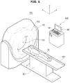
- FIG. 1 is a perspective view illustrating a computed tomographic (CT) apparatus, according to an exemplary embodiment of the present disclosure.
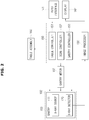
- FIG. 2 is a control block diagram illustrating a CT apparatus, according to an exemplary embodiment of the present disclosure.
- CT computed tomographic
- an X-ray scanner 102 is arranged inside a housing 101 of a CT apparatus 100.
- the X-ray scanner 102 includes a gantry 103, inside which an X-ray source 111 and an X-ray detector 120 are mounted to face each other as shown in FIG. 3 , the X-ray detector 120 detecting X-rays irradiated from the X-ray source 111.
- a subject 30 is placed on a table assembly 160 having a patient table 162, on which the subject 30 lies, and a table supporter 161 for supporting the patient table 162.
- a driving device such as a motor, a gear, etc., for supplying power to the patient table 162.
- the patient table 162 is moved toward a bore 105 along the z-axis, and the subject 30 is then put within the bore 105.
- the X-ray source 111 irradiates X-rays while turning 360 degrees (turning a full circle) or more, and the X-rays penetrating the subject 30 may be detected by the X-ray detector 120.
- the CT apparatus 100 includes a user interface for presenting the user with information and receiving control commands from the user, and the user interface includes an input interface 141 and a display 142.
- An apparatus equipped with the input interface 141 and the display 142 may be referred to as a workstation 140 or a host device.
- the CT apparatus 100 in accordance with an exemplary embodiment includes the X-ray scanner 102 including the X-ray source 111 for producing and irradiating X-rays to a subject and the X-ray detector 120 for detecting X-rays that penetrate the subject, to obtain digital X-ray data.
- the CT apparatus 100 further includes a gantry motor 107 and a controller 150 for controlling the rotation of the gantry 103 and operations of the X-ray source 111 and the X-ray detector 120 equipped in the gantry 103.
- the CT apparatus 100 further includes the table assembly 160, and an image processor 130 for creating a tomographic image of the subject by reconstructing the X-ray data.
- the CT apparatus 100 further includes the input interface 141 for receiving the user's command to control the CT apparatus 100, and the display 142 for displaying a screen related to controlling the CT apparatus 100 or a tomographic image of the subject.
- the X-ray source 111 produces and irradiates X-rays having an energy band, and the X-ray detector 120 detects the X-rays, converts them to digital X-ray data, and sends the conversion result to the image processor 130. Details of the X-ray source 111 and X-ray detector 120 will be described below.
- the image processor 130 reconstructs a tomographic image of the inside of the subject, using the X-ray data sent from the X-ray detector 120.
- an image reconstruction method there may be an iterative method, a direct Fourier method, a filtered back projection method, and the like.
- the image processor 130 may compensate the data obtained from a counting detection region, using data obtained from an integrative detection region, as will be described later in detail.
- the tomographic image reconstructed by the image processor 130 may be sent to the display 142, which in turn displays the tomographic image of the subject.
- the input interface 141 and the display 142 may be included in the workstation 140.
- the input interface 141 may be implemented with at least one of various input devices, such as a mouse, a keyboard, a trackball, a touch panel, etc.
- the display 142 may be implemented with at least one of various display devices, such as Light Emitting Diodes (LEDs), organic LEDs (OLEDs), Plasma Display Panel (PDP), Cathode-Ray Tube (CRT), etc.
- LEDs Light Emitting Diodes
- OLEDs organic LEDs
- PDP Plasma Display Panel
- CRT Cathode-Ray Tube
- the user may input control commands for all operation of the CT apparatus 100, including a command regarding movement of the patient table 162, a command regarding selection of scan mode, a command regarding scan condition, a command regarding image display, etc.
- the display 142 may display a screen for helping the user input a control command, a screen for representing control status of the CT apparatus 100, and an image created by the image processor 130.
- the controller 150 controls operations of the CT apparatus 100.
- the controller 150 includes a table controller 151 for controlling the movement of the patient table 162, a scan controller 152 for controlling scan-related parameters, scan mode, etc., by taking into account a scanning part of the subject, a purpose for diagnosis, characteristics of the subject, etc., and a gantry controller 153 for controlling rotation of the gantry 103, activation of the detector assembly 120, etc.
- the table controller 151 may control moving distance and moving direction of the patient table 162 for a target scanning region of the subject that lies on the patient table 162 to be within the bore 105. For this, the table controller 151 may send a control signal to drive the patient table 162 to the table assembly 160.
- the scan controller 152 may perform an Auto Exposure Controller (AEC) function that automatically controls exposure parameters, control a scan mode, and control activation of the detector assembly 120 based on whether data is to be obtained from the integrative detection region or the counting detection region.
- AEC Auto Exposure Controller
- the scan controller 152 may control the exposure parameters, such as tube voltage, tube current, exposure time, filter type and thickness, target material of a positive electrode, focal spot size, etc., that are applied to the X-ray source 111, in performing the AEC function.
- the exposure parameters such as tube voltage, tube current, exposure time, filter type and thickness, target material of a positive electrode, focal spot size, etc.
- the scan controller 152 may control thickness or the number of slices obtained through one-time scanning, and determine which one of the counting detection region and integrative detection region is used to obtain respective slices in case of obtaining multiple slices or control activation of respective detection regions according to the determination result.
- the scan controller 152 may actively execute control or at the request of the user.
- the gantry controller 153 may control the number of rotations or speed of rotation of the gantry 103, by sending a control signal to the gantry motor 107 that supplies a driving force for rotation to the gantry 103.
- FIG. 3 is a cross-sectional view illustrating an X-ray scanner of a CT apparatus, according to an exemplary embodiment of the present disclosure.
- FIG. 4 is a cross-sectional view illustrating internal components of an X-ray source of a CT apparatus, according to an exemplary embodiment of the present disclosure.
- an X-ray scanner includes the gantry 103, and the X-ray source 111 and the X-ray detector 120 that are mounted inside the gantry 103 to face each other.
- the gantry 103 may rotate 360 degrees around the bore 105.
- a collimator 113 is placed ahead of the X-ray source 111 in the direction of X-ray irradiation for controlling the width of an X-ray beam irradiated from the X-ray source 111. Accordingly, the collimator 113 may reduce beam scattering in other directions, thereby lowering the risk of the subject being exposed to radiation.
- the collimator arranged ahead of the X-ray detector 120 may cancel scattered rays, and control the width of an X-ray beam that penetrates the subject, thereby determining a thickness of the slice.
- the X-ray source 111 also referred to as an X-ray tube, may be supplied with power from a power supply for producing X-rays.
- the X-ray tube 111 is implemented with a two-pole vacuum tube including a positive electrode 111c and a negative electrode 111e.
- the negative electrode 111e includes a filament 111h and a focusing electrode 111g that focuses electrons, and the focusing electrode 111g is also called a focusing cup.
- Thermions are generated by making the inside of a glass tube 111a in a high vacuum state of about 10 mmHg and heating the filament 111h of the negative electrode 111e to a high temperature.
- a tungsten filament may be used, which may be heated by applying a current to an electric wire 111f coupled with the filament 111h.
- the positive electrode 111c is mainly formed of copper, and a target material 111d is applied or disposed on the side that faces the negative electrode 111e, the target material including a high resistive material, such as Cr, Fe, Co, Ni, W, Mo, or the like.
- the target material is tilted at an angle, and the greater the tilting angle, the smaller the focus spot size.
- the focus spot size may vary depending on the tube voltage, tube current, size of the filament, size of the focusing electrode, distance between the positive and negative electrodes.
- thermions When a high voltage is applied across the negative and positive electrodes 111e and 111c, thermions get accelerated and collide with the target material 111d of the positive electrode, thus producing X-rays.
- the X-ray is irradiated out through a window 111i that may use a thin film of Beryllium.
- a filter may be placed on the front or rear side of the window 111i, to filter X-rays in an energy band.
- the target material 111d may be rotated by a rotor 111b. While the target material 111d is rotating, heat build-up rate may increase more than ten times per unit area as compared with an occasion where the target material 111d is stationary, and the focal spot size may decrease.
- a voltage applied across the negative and positive electrodes 111e and 111c of the X-ray tube 111 is called a tube voltage whose magnitude may be represented by a crest value kVp.
- a tube voltage whose magnitude may be represented by a crest value kVp.
- a current flowing in the X-ray tube 111 is called a tube current, which may be represented by an average value mA.
- a tube current As the tube current increases, the number of thermions emitted from the filament increases and as a result, a dose of X-rays (the number of photons of X-rays) produced from collision with the target material 111d increases.
- the energy of X-radiation may be controlled by the tube voltage, and the intensity or dose of X-rays may be controlled by the tube current and time for being exposed to X-rays.
- the energy, intensity or dose of X-rays may be determined depending on characteristics of the subject, such as type and thickness of the subject, or a purpose of diagnosis.
- the X-ray source 111 may irradiate monochromatic X-rays or polychromatic X-rays. In the case the X-ray source 111 irradiates polychromatic X-rays in an energy band, the energy band of the X-rays to be irradiated may be defined by upper and lower limits.
- the upper limit of the energy band i.e., a maximum energy of X-rays to be irradiated
- the lower limit of the energy band i.e., a minimum energy of X-rays to be irradiated
- a filter arranged in the irradiation direction of the X-rays.
- the filter may pass or filter out X-rays of an energy band. Accordingly, with the filter arranged on the front or back side of the window 111i for filtering the X-rays in an energy band, the X-rays of the energy band may be filtered.
- the X-ray beam quality may be hardened, thereby increasing the lower limit of the energy band and an average energy level of X-rays to be irradiated. It may further reduce radiation to which the subject is exposed.
- a bow-tie filter as will be described later in connection with FIG. 17 may serve as the filter, or a separate filter having the function as described above may exist in addition to the bow-tie filter.
- a cross-section of the X-ray detector 120 may have the form of an arch, on the top of which detection elements 121 are arranged for detecting X-rays and converting them to electric signals.
- the detection elements 121 may form an array of multiple detection elements, each detection element serving as a pixel.
- the detection elements 121 may be classified by schemes for converting detected X-rays to electric signals or methods for obtaining electric signals, i.e., classified into those using a direct scheme and an indirect scheme for converting the detected X-rays to electric signals.
- the detection elements 121 may also be divided into those having a charge integration mode for storing charges for a period of time and obtaining a signal from the charges and a photon counting mode for counting the number whenever a signal is generated by a single X-ray photon, based on the method of obtaining the electric signal.
- the detection element converts the movements into an electric signal.
- the material used for the photo detector may be e.g., a-Se, CdZnTe, HgI2, PbI2, etc.
- a scintillator may be mounted on the top of the detection element, which is responsive to X-rays irradiated from the X-ray source 111 to emit photons having wavelengths of visible rays, and the photo detector may detect the photons and convert them to an electric signal.
- the material used for the photo detector in the indirect conversion scheme may be e.g., a-Si, and the scintillator may be a GADOX scintillator in the form of a thin film, or a micro column type or needle structure type CSI (T1).
- the detection elements 121 may employ a proper one of the direct and indirect conversion schemes, and it is also possible that respective regions of the detection elements 121 as will be described later may use different conversion schemes.
- the indirect conversion scheme may be applied for the integrative detection region
- the direct conversion scheme may be applied for the counting detection region.
- the inside of the subject may be imaged even with a lower dose of radiation, and the image may have a good signal to noise (SNR) ratio.
- SNR signal to noise
- the detection elements 121 may use the photon counting scheme. Arrangement and structure of the detection elements 121 will now be described in detail.
- the CT apparatus 100 may establish a scanning region before CT scanning of the subject. If information about a scanning region is input or designated by the user, the CT apparatus 100 may obtain a tomographic image of the scanning region.
- the CT apparatus 100 may capture a scout image.
- the scout image may be an X-ray image of a part or entire region of the subject.
- the user may designate a scanning region, which is a target region for CT scanning, among the part or entire region of the subject.
- the scout image may have unclear boundaries between substances that make up the subject. The user may then have difficulty designating a precise scanning region.
- the CT apparatus 100 helps the user to designate a precise scanning region, by separating images of the substances (hereinafter, referred to as substance images) from the scout image.
- the CT apparatus 100 that determines a scanning region based on the substance images will now be described in detail.
- the CT apparatus 100 in accordance with an exemplary embodiment includes the X-ray scanner 102 for capturing a scout image to establish a scanning region of a subject, the image processor 130 for creating respective images of a plurality of substances that make up the subject based on the captured scout image, the display 142 for displaying at least one of the multiple substance images, and the input interface 141 for receiving an input of a scanning region with respect to the displayed substance image.
- the X-ray scanner 102 includes the X-ray source 111, the X-ray detector 120, and the gantry 103 having the X-ray source 111 and the X-ray detector 120 mounted thereon.
- the X-ray scanner 102 rotates the gantry 103, and performs CT scanning by irradiating X-rays to the scanning region of the subject from the X-ray source 111 mounted on the rotating gantry 103.
- the gantry 103 may be rotated around a predetermined rotating shaft.
- the X-ray scanner 102 also captures a scout image for establishing a scanning region, a target for CT scanning. A method of capturing a scout image using the X-ray scanner 102 will now be described.
- FIGS. 5A and 5B are views illustrating a method of capturing a scout image in a CT apparatus, according to an exemplary embodiment of the present disclosure.
- the X-ray source 111 and the X-ray detector 120 are arranged to face each other, and are able to rotate around the z-axis by rotation of the gantry 103.
- the subject 30 is put on one side of the patient table 162.
- the patient table 162 is movable along the z-axis, and moves the subject 30 into the inside of the bore.
- the scout image is an image for establishing a scanning region, and may thus include information regarding a predetermined region of the subject 30, including the scanning region. Accordingly, the predetermined region of the subject 30 may be scanned by moving the patient table 162 in the direction parallel with the rotating shaft of the gantry 103.
- X-rays may be irradiated to the head of the subject 30, as shown in FIG. 5A .
- the patient table 162 is controlled to be moved in the direction of the arrow shown in FIG. 5A
- the subject 30 is moved along with the patient table 162.
- X-rays may be irradiated to the abdomen of the subject 30, as shown in FIG. 5B .
- the subject 30 may be scanned from head to abdomen.
- the gantry 103 may not be rotated, thus to fix the position of the X-ray source 111 and X-ray detector 120.
- the X-ray source 111 fixed at a position obtains a scout image, which is a cross-sectional image of the subject 30 in the xz-plane by irradiating X-rays to the moving subject 30.
- providing substance images separated from the scout image may facilitate the user to establish a scanning region.
- FIGS. 6A , 6B , and 6C are scout images that are obtained by a CT apparatus, according to exemplary embodiments of the present disclosure.
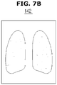
- FIGS. 7A and 7B are substance images that are obtained by a CT apparatus, according to exemplary embodiments of the present disclosure.
- FIGS. 8A , 8B , and 8C are overlaid images that are obtained by overlaying multiple substance images in a CT apparatus, according to exemplary embodiments of the present disclosure.
- the X-ray source 111 may irradiate multi-energy X-rays to the subject.
- the X-ray source 111 may irradiate X-rays having a predetermined energy band to the subject.
- the energy band of X-rays to be irradiated may be controlled by the tube voltage.
- the X-ray detector 120 may detect X-rays that penetrate the subject and classify them by multiple energy bands.
- the X-ray detector 120 may be implemented by a photon counting detector.
- the photon counting detector may set multiple threshold energy levels, and count photons greater than the respective threshold energy levels to divide them by respective energy bands.
- the X-ray detector 120 may divide the detected X-rays by low, middle, and high energy bands.
- the X-rays divided by multiple energy bands may be sent to the image processor 130.
- the image processor 130 may use the X-rays divided by the multiple energy bands to obtain multiple scout images for the multiple energy bands.
- the image processor 130 may obtain a scout image for the low energy band (hereinafter, referred to as a low energy scout image), a scout image for the middle energy band (a middle energy scout image), and a scout image for the high energy band (a high energy scout image).
- a low energy scout image a scout image for the low energy band
- a middle energy scout image a scout image for the middle energy band
- a scout image for the high energy band a high energy scout image
- FIGS. 6A , 6B , and 6C are a low energy scout image, a middle energy scout image, and a high energy scout image, respectively.
- the display 142 displays the low energy scout image, the middle energy scout image, and the high energy scout image.
- the image processor 130 may separate multiple substance images from the multiple scout images obtained as described above.
- An attenuation coefficient refers to what numerically represents an extent of X-ray deterioration, and may vary by substances inside the subject, or energy bands of X-rays irradiated.
- the image processor 130 may obtain multiple substance images using the multiple scout images.
- FIGS. 7A and 7B are an image of bones and an image of tissues, among the substance images separated from the multiple scout images, respectively.
- the display 142 displays the substance images separated in this way. Compared with the scout image, the substance images may have clear boundaries of substances that make up the subject.
- the input interface 141 may receive a scanning region on the displayed substance image.
- the scanning region may be a target for CT scanning.
- the display 142 may display the substance image in various ways. Exemplary embodiments of a method of overlaying and displaying substance images will be described in connection with FIGS. 8A to 8C .
- the display 142 may display at least two of substance images separated from multiple scout images by overlaying them. Transparency of an overlaid substance image may be determined according to an input of the user.
- the display 142 displays an image of bones and an image of tissues by overlaying them. If the user wants to emphasize the image of tissues, the user may increase opaqueness of the image of tissues. As a result, the user may check the tissue arrangement as well as the outline of the bones.
- the display 142 displays overlaid images in which substance images have different opaqueness controlled by the location of a control bar c.
- the display 142 displays overlaid images in which an image of bones has higher opaqueness than an image of tissues.
- the display 142 displays overlaid images in which the image of bones has the same opaqueness as that of the image of tissues.
- the display 142 displays overlaid images in which an image of tissues has higher opaqueness than an image of bones.
- the user may be provided with overlaid images in which a desired substance is emphasized by manipulating the control bar.
- the display 142 may display at least one of the multiple scout images and at least one of the multiple substance images by overlaying them.
- FIG. 9 is a view illustrating a method of displaying a substance image in a CT apparatus, according to an exemplary embodiment of the present disclosure.
- the display 142 displays a high energy image of a plurality of scout images and an image of tissues of a plurality of substance images by overlaying them.
- the display 142 may match at least one of the plurality of substance images with a reference organ image, and display the matching result.
- a scanning region may be determined by a region where an organ inside the subject exists, and thus providing the position of the reference organ image may help the user easily establish the scanning region.
- An organ as herein used may refer to an organ inside the subject, such as the heart, liver, lung, etc., identified by its function, and each organ may be made of one or more substances that make up the subject.
- a reference organ image may be an image obtained by modeling a subject, e.g., an organ of a human body.
- the reference organ image may be determined by obtaining information about the organ of the subject from a predetermined sample. For example, information about an organ, such as the feature information of the organ may be obtained from a predetermined sample, and a reference organ image may be created based on an average of a plurality of pieces of information obtained from the sample. Respective reference organ images may be created for a plurality of organs of the subject.
- a method of obtaining the reference organ image may employ Atlas modeling, but is not limited thereto.
- the controller 150 may match a reference organ image to a substance image.
- FIGS. 10A , 10B , and 10C are views illustrating a method of matching a reference organ image to a substance image in a CT apparatus, according to an exemplary embodiment of the present disclosure.
- Image R may refer to a reference organ image.
- the reference organ image may be created based on the organ obtained from a predetermined sample, it may represent a feature of the organ. Accordingly, a region, which is most similar to the reference organ image, may be checked in a substance image separated from a scout image, to match the coordinates of the two images.
- the region most similar to the reference organ image may be found by varying the reference organ image R in the fixed image of the substance. Consequently, as shown in FIG. 10C , the reference organ image R is matched to the substance image.
- the display 142 displays a result of matching the reference organ image to the substance image. At this time, the display 142 may emphasize the reference organ image R.
- matching a reference organ image to a substance image may enable the boundary and feature of the substance to be seen more clearly.
- the display 142 may also display the resultant image from matching the reference organ image to the substance image to overlay at least one of the plurality of scout images.
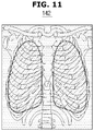
- FIG. 11 is a view illustrating a method of displaying a substance image in a CT apparatus, according to another exemplary embodiment of the present disclosure.
- the display 142 may display a matched image obtained by matching a reference organ image to a substance image, and a scout image by overlaying them.
- the display 142 displays the matched image and a high energy scout image of FIG. 6C by overlaying them.
- the display 142 may also display a recommended scanning region based on the matched image obtained by matching the reference organ image to the substance image.
- the display 142 may display a region of the substance image corresponding to the reference organ image as a recommended scanning region.
- the input interface 141 may receive an organ of interest among many different internal organs of the subject.
- the display 142 may match a reference organ image for the organ A to a substance image and display the resultant image.
- the display 142 may indicate a recommended scanning region on the displayed substance image. Displaying both the substance image and the recommended scanning region may offer the user a precise position of the recommended scanning region.
- the display 142 may display at least one of a plurality of substance images. The user may visually check this, and then designate a scanning region through the input interface 141.
- the controller 150 may perform CT scanning for the scanning region by rotating the gantry 103.
- the controller 150 may determine the scanning region based on at least one of the plurality of substance images.
- the controller 150 may determine the scanning region by comparing at least one of the plurality of substance images and a predetermined reference organ image.
- the controller 150 may compare the substance image and the reference organ image after matching the reference organ image to the at least one of the plurality of substance images.
- the user may input an organ of interest through the input interface 141.
- the controller 150 may compare the substance image and a reference organ image for the organ A.
- the controller 150 may determine a scanning region for the input organ of interest.
- the controller 150 may determine a scanning region to include a region where the organ A is displayed, by comparing the substance image and the reference organ image.
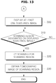
- FIG. 12 is a flowchart illustrating a method of creating multiple substance images included in a method of controlling a CT apparatus, according to an exemplary embodiment of the present disclosure.
- X-rays are irradiated to a subject, in operation 200.
- X-rays may be irradiated to the subject while the subject is moving in the direction parallel with a rotating shaft of the gantry 103.
- the X-rays irradiated may be multi-energy X-rays.
- X-rays that penetrate the subject are detected, in operation 210.
- the X-rays penetrating the subject may be detected by a photon counting detector.
- the detected X-rays are divided by energy bands, in operation 220.
- the detected X-rays may also have a wide spectrum of energy.
- the wide spectrum of energy may be divided into multiple energy bands, and the detected X-rays may be divided by the multiple energy bands.
- the scout image may be an image for establishing a scanning region before CT scanning.
- a first scout image for a first energy band of the multiple energy bands is obtained, in operation 230-1.
- the first scout image for the first energy band may be obtained based on the detected X-rays that have the first energy band.
- a second scout image for a second energy band is obtained, in operation 230-2.
- an mth scout image for an mth energy band is obtained, in operation 230-m. Consequently, m scout images may be obtained, m is a positive integer.
- An image of a first substance of a plurality of substances that make up the subject is separated from the m scout images, in operation 240-1.
- an attenuation coefficient may be used.
- an image of a second substance of the plurality of substances is separated from the m scout images, in operation 240-2.
- an image of an nth substance of the plurality of substances is separated from the m scout images, in operation 240-n. Consequently, n substance images may be obtained, n is a positive number.
- FIG. 13 is a flowchart illustrating a method of displaying multiple substance images included in a method of controlling the CT apparatus, according to an exemplary embodiment of the present disclosure.
- At least one substance image of a plurality of substance images is displayed, in operation 300.
- the substance image to be displayed may be determined by an organ of interest input by the user.
- CT scanning for the scanning region is performed, in operation 320.
- a tomographic image of the scanning region is obtained, in operation 330.
- FIG. 14 is a flowchart illustrating a method of displaying multiple substance images included in a method of controlling a CT apparatus, according to another exemplary embodiment of the present disclosure.
- At least one substance image of multiple substance images and at least one scout image of multiple scout images are displayed by overlaying them, in operation 400.
- the substance image to be displayed may be determined by an organ of interest input by the user.
- the substance image and the scout image may be displayed by varying their respective opaqueness. For example, to emphasize the substance image for display, the opaqueness of the substance image may be increased.
- CT scanning for the scanning region is performed, in operation 420.
- a tomographic image of the scanning region is obtained, in operation 430.
- Displaying the substance image and the scout image to overlay each other may offer the user more precise information for establishing a scanning region.
- FIG. 15 is a flowchart illustrating a method of displaying multiple substance images included in a method of controlling a CT apparatus, according to another exemplary embodiment of the present disclosure.
- a predetermined reference organ image is matched to at least one substance image of multiple substance images, in operation 500.
- the substance image and the reference organ image to be displayed may be determined by an organ of interest input by the user.
- a reference organ image may be an image obtained by modeling a subject, e.g., an organ of a human body.
- a method of obtaining the reference organ image may employ Atlas modeling, but is not limited thereto.
- the at least one substance image and the matching reference organ image are displayed by overlaying them, in operation 510.
- the substance image and the reference organ image may be displayed by varying their respective opaqueness. For example, to emphasize the reference organ image for display, the opaqueness of the reference organ image may be increased.
- CT scanning for the scanning region is performed, in operation 530.
- a tomographic image of the scanning region is obtained, in operation 540.
- Matching the substance image and the reference organ image may offer the user more precise position of the organ.
- FIG. 16 is a flowchart illustrating a method of displaying multiple substance images included in a method of controlling a CT apparatus, according to another exemplary embodiment of the present disclosure.
- a predetermined reference organ image is matched to at least one substance image of multiple substance images, in operation 600.
- the substance image and the reference organ image to be displayed may be determined by an organ of interest input by the user.
- At least one scout image of multiple scout images, the at least one substance image, and the matching reference organ image are displayed by overlaying them, in operation 610.
- the substance image and the reference organ image may be displayed by varying their respective opaqueness. For example, to emphasize the reference organ image for display, the opaqueness of the reference organ image may be increased.
- CT scanning for the scanning region is performed, in operation 630.
- a tomographic image of the scanning region is obtained, in operation 640.
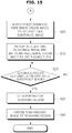
- FIG. 17 is a flowchart illustrating a method of displaying multiple substance images included in a method of controlling the CT apparatus, according to another exemplary embodiment of the present disclosure.
- a predetermined reference organ image is matched to at least one substance image of multiple substance images, in operation 700.
- the substance image and the reference organ image to be displayed may be determined by an organ of interest input by the user.
- a reference organ image may be an image obtained by modeling a subject, e.g., an organ of a human body.
- a method of obtaining the reference organ image may employ Atlas modeling, but is not limited thereto.
- the at least one substance image and the matching reference organ image are displayed by overlaying them, and at the same time, a scanning region is recommended on the displayed image, in operation 710. Both the overlay image and the recommended scanning region may be displayed together.
- CT scanning for the scanning region is performed, in operation 730.
- a tomographic image of the scanning region is obtained, in operation 740.
- Recommending the scanning region to be a region similar to the reference organ image may help the user establish a more precise scanning region.
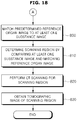
- FIG. 18 is a flowchart illustrating a method of controlling a CT apparatus, according to an exemplary embodiment of the present disclosure.
- a predetermined reference organ image is matched to at least one substance image of multiple substance images, in operation 800.
- the substance image and the reference organ image to be displayed may be determined by an organ of interest input by the user.
- a reference organ image may be an image obtained by modeling a subject, e.g., an organ of a human body.
- a method of obtaining the reference organ image may employ Atlas modeling, but is not limited thereto.
- a scanning region is determined by comparing the at least one substance image and the matching reference organ image, in operation 810.
- a region most similar to the reference organ image may be determined to be the scanning region in the substance image.
- CT scanning for the scanning region is performed, in operation 820.
- a tomographic image of the scanning region is obtained, in operation 830.
- Such active determination of the scanning region without separate input from the user may increase convenience for the user.
- an image of a constituent substance (or a substance image) of a subject may be provided for the user, facilitating establishment of a more precise scanning region.
- a scanning region may be actively established based on an internal organ input by the user. This eliminates intervention of the user to input a separate scanning region, and thus includes less additional operations other than CT scanning.
- the exemplary embodiments may also be implemented through computer-readable code and/or instructions on a medium, e.g., a non-transitory computer-readable medium, to control at least one processing element to implement any above-described exemplary embodiments.
- the medium may correspond to any medium or media which may serve as a storage and/or perform transmission of the computer-readable code.
- the computer-readable code may be recorded and/or transferred on a medium in a variety of ways, and examples of the medium include recording media, such as magnetic storage media (e.g., ROM, floppy disks, hard disks, etc.) and optical recording media (e.g., compact disc read only memories (CD-ROMs) or digital versatile discs (DVDs)), and transmission media such as Internet transmission media.
- the medium may have a structure suitable for storing or carrying a signal or information, such as a device carrying a bitstream according to one or more exemplary embodiments.
- the medium may also be on a distributed network, so that the computer-readable code is stored and/or transferred on the medium and executed in a distributed fashion.
- the processing element may include a processor or a computer processor, and the processing element may be distributed and/or included in a single device.
Landscapes
- Health & Medical Sciences (AREA)
- Life Sciences & Earth Sciences (AREA)
- Engineering & Computer Science (AREA)
- Medical Informatics (AREA)
- Physics & Mathematics (AREA)
- Heart & Thoracic Surgery (AREA)
- Surgery (AREA)
- Nuclear Medicine, Radiotherapy & Molecular Imaging (AREA)
- Optics & Photonics (AREA)
- Pathology (AREA)
- Radiology & Medical Imaging (AREA)
- Biomedical Technology (AREA)
- Biophysics (AREA)
- Molecular Biology (AREA)
- High Energy & Nuclear Physics (AREA)
- Animal Behavior & Ethology (AREA)
- General Health & Medical Sciences (AREA)
- Public Health (AREA)
- Veterinary Medicine (AREA)
- Pulmonology (AREA)
- Theoretical Computer Science (AREA)
- Human Computer Interaction (AREA)
- Mathematical Physics (AREA)
- Apparatus For Radiation Diagnosis (AREA)
Description
- Apparatuses and methods consistent with exemplary embodiments relate to a computed tomographic apparatus and a method of controlling the same.
- X-ray imaging apparatuses are devices for allowing the user to see an internal structure of a subject by irradiating X-rays to the subject and using X-rays that passed through the subject. X-ray transmittance is different depending on the tissue of a subject, and the internal structure of the subject may be imaged using an attenuation coefficient quantified from the X-ray transmittance.
- The X-ray imaging apparatus may be classified into a general radiographic apparatus for obtaining a projection image of the subject by transmitting X-rays from one direction, and a computed tomographic (CT) apparatus for reconstructing an image with a computer by transmitting X-rays in different directions. The CT apparatus is also referred to as a computed tomographic scanning apparatus, or computerized tomographic scanning apparatus.
- For the CT apparatus to image a particular substance inside the subject, a region for scanning needs to be precisely established. Accordingly, a scout image for establishing the scanning region may be obtained before a CT scan is performed.
- As an example of relevant prior art, reference is made here to
US-2004/101087 , which discloses a CT apparatus and method of controlling the same according to the preamble of claims 1 and 7. - Exemplary embodiments address at least the above problems and/or disadvantages and other disadvantages not described above. Also, the exemplary embodiments are not required to overcome the disadvantages described above, and may not overcome any of the problems described above.
- Aspects of the exemplary embodiments provide a computed tomographic apparatus and a method of controlling the same, which provides a user with an image of a substance of a subject to receive an input of a scanning region from the user.
- In accordance with an aspect of an exemplary embodiment, there is provided a computed tomographic (CT) apparatus including combined features of the appended independent apparatus claim.
- In accordance with an aspect of another exemplary embodiment, there is provided a method of controlling a computed tomographic (CT) apparatus, the method including combined features of the appended independent method claim.
- The above and other aspects will become apparent and more readily appreciated from the following description of the exemplary embodiments, taken in conjunction with the accompanying drawings of which:
-
FIG. 1 is a perspective view illustrating a computed tomographic (CT) apparatus, according to an exemplary embodiment of the present disclosure; -
FIG. 2 is a control block diagram illustrating a CT apparatus, according to an exemplary embodiment of the present disclosure; -
FIG. 3 is a cross-sectional view illustrating an X-ray scanner of a CT apparatus, according to an exemplary embodiment of the present disclosure; -
FIG. 4 is a cross-sectional view illustrating internal components of an X-ray source of a CT apparatus, according to an exemplary embodiment of the present disclosure; -
FIGS. 5A and5B are views illustrating a method of capturing a scout image in a CT apparatus, according to an exemplary embodiment of the present disclosure; -
FIGS. 6A ,6B , and6C are scout images that are obtained by a CT apparatus, according to exemplary embodiments of the present disclosure; -
FIGS. 7A and7B are substance images that are obtained by a CT apparatus, according to exemplary embodiments of the present disclosure; -
FIGS. 8A ,8B , and8C are overlaid images that are obtained by overlaying multiple substance images in a CT apparatus, according to exemplary embodiments of the present disclosure; -
FIG. 9 is a view illustrating a method of displaying a substance image in a CT apparatus, according to an exemplary embodiment of the present disclosure; -
FIGS. 10A ,10B , and10C are views illustrating a method of matching a reference organ image to a substance image in a CT apparatus, according to an exemplary embodiment of the present disclosure; -
FIG. 11 is a view illustrating a method of displaying a substance image in a CT apparatus, according to another exemplary embodiment of the present disclosure; -
FIG. 12 is a flowchart illustrating a method of creating multiple substance images included in a method of controlling a CT apparatus, according to an exemplary embodiment of the present disclosure; -
FIG. 13 is a flowchart illustrating a method of displaying multiple substance images included in a method of controlling a CT apparatus, according to an exemplary embodiment of the present disclosure; -
FIG. 14 is a flowchart illustrating a method of displaying multiple substance images included in a method of controlling a CT apparatus, according to another exemplary embodiment of the present disclosure; -
FIG. 15 is a flowchart illustrating a method of displaying multiple substance images included in a method of controlling a CT apparatus, according to another exemplary embodiment of the present disclosure; -
FIG. 16 is a flowchart illustrating a method of displaying multiple substance images included in a method of controlling a CT apparatus, according to another exemplary embodiment of the present disclosure; -
FIG. 17 is a flowchart illustrating a method of displaying multiple substance images included in a method of controlling a CT apparatus, according to another exemplary embodiment of the present disclosure; and -
FIG. 18 is a flowchart illustrating a method of controlling a CT apparatus, according to an exemplary embodiment of the present disclosure. - A computed tomographic (CT) apparatus and method of controlling the same will now be described in detail with reference to accompanying drawings.
- In the following description, like drawing reference numerals are used for like elements, even in different drawings. The matters defined in the description, such as detailed construction and elements, are provided to assist in a comprehensive understanding of the exemplary embodiments. However, it is apparent that the exemplary embodiments can be practiced without those defined matters. Also, well-known functions or constructions are not described in detail because they would obscure the description with unnecessary detail.
- The term 'subject' as herein used may refer to a patient, but is not limited thereto. In addition, the term 'user' as herein used may refer to a doctor, but is not limited thereto. In addition, the terms such as 'unit,' '-er (-or),' and 'module' described in the specification refer to an element configured to perform at least one function or operation, and may be implemented in hardware, software, or a combination of hardware and software.
-
FIG. 1 is a perspective view illustrating a computed tomographic (CT) apparatus, according to an exemplary embodiment of the present disclosure.FIG. 2 is a control block diagram illustrating a CT apparatus, according to an exemplary embodiment of the present disclosure. - Referring to
FIGS. 1 and2 , inside ahousing 101 of aCT apparatus 100, anX-ray scanner 102 is arranged. - The
X-ray scanner 102 includes agantry 103, inside which anX-ray source 111 and anX-ray detector 120 are mounted to face each other as shown inFIG. 3 , theX-ray detector 120 detecting X-rays irradiated from theX-ray source 111. - A
subject 30 is placed on atable assembly 160 having a patient table 162, on which thesubject 30 lies, and atable supporter 161 for supporting the patient table 162. Inside the table supporter, there may be a driving device, such as a motor, a gear, etc., for supplying power to the patient table 162. - The patient table 162 is moved toward a
bore 105 along the z-axis, and thesubject 30 is then put within thebore 105. When thegantry 103 is rotated while thesubject 30 is put within thebore 105, theX-ray source 111 irradiates X-rays while turning 360 degrees (turning a full circle) or more, and the X-rays penetrating thesubject 30 may be detected by theX-ray detector 120. - The
CT apparatus 100 includes a user interface for presenting the user with information and receiving control commands from the user, and the user interface includes aninput interface 141 and adisplay 142. An apparatus equipped with theinput interface 141 and thedisplay 142 may be referred to as aworkstation 140 or a host device. - Referring to
FIG. 2 , theCT apparatus 100 in accordance with an exemplary embodiment includes theX-ray scanner 102 including theX-ray source 111 for producing and irradiating X-rays to a subject and theX-ray detector 120 for detecting X-rays that penetrate the subject, to obtain digital X-ray data. TheCT apparatus 100 further includes agantry motor 107 and acontroller 150 for controlling the rotation of thegantry 103 and operations of theX-ray source 111 and theX-ray detector 120 equipped in thegantry 103. TheCT apparatus 100 further includes thetable assembly 160, and animage processor 130 for creating a tomographic image of the subject by reconstructing the X-ray data. TheCT apparatus 100 further includes theinput interface 141 for receiving the user's command to control theCT apparatus 100, and thedisplay 142 for displaying a screen related to controlling theCT apparatus 100 or a tomographic image of the subject. - The
X-ray source 111 produces and irradiates X-rays having an energy band, and theX-ray detector 120 detects the X-rays, converts them to digital X-ray data, and sends the conversion result to theimage processor 130. Details of theX-ray source 111 andX-ray detector 120 will be described below. - The
image processor 130 reconstructs a tomographic image of the inside of the subject, using the X-ray data sent from theX-ray detector 120. As an image reconstruction method, there may be an iterative method, a direct Fourier method, a filtered back projection method, and the like. - Furthermore, the
image processor 130 may compensate the data obtained from a counting detection region, using data obtained from an integrative detection region, as will be described later in detail. - The tomographic image reconstructed by the
image processor 130 may be sent to thedisplay 142, which in turn displays the tomographic image of the subject. - The
input interface 141 and thedisplay 142 may be included in theworkstation 140. Theinput interface 141 may be implemented with at least one of various input devices, such as a mouse, a keyboard, a trackball, a touch panel, etc., and thedisplay 142 may be implemented with at least one of various display devices, such as Light Emitting Diodes (LEDs), organic LEDs (OLEDs), Plasma Display Panel (PDP), Cathode-Ray Tube (CRT), etc. - The user may input control commands for all operation of the
CT apparatus 100, including a command regarding movement of the patient table 162, a command regarding selection of scan mode, a command regarding scan condition, a command regarding image display, etc. - The
display 142 may display a screen for helping the user input a control command, a screen for representing control status of theCT apparatus 100, and an image created by theimage processor 130. - The
controller 150 controls operations of theCT apparatus 100. Thecontroller 150 includes atable controller 151 for controlling the movement of the patient table 162, ascan controller 152 for controlling scan-related parameters, scan mode, etc., by taking into account a scanning part of the subject, a purpose for diagnosis, characteristics of the subject, etc., and agantry controller 153 for controlling rotation of thegantry 103, activation of thedetector assembly 120, etc. - The
table controller 151 may control moving distance and moving direction of the patient table 162 for a target scanning region of the subject that lies on the patient table 162 to be within thebore 105. For this, thetable controller 151 may send a control signal to drive the patient table 162 to thetable assembly 160. - The
scan controller 152 may perform an Auto Exposure Controller (AEC) function that automatically controls exposure parameters, control a scan mode, and control activation of thedetector assembly 120 based on whether data is to be obtained from the integrative detection region or the counting detection region. - The
scan controller 152 may control the exposure parameters, such as tube voltage, tube current, exposure time, filter type and thickness, target material of a positive electrode, focal spot size, etc., that are applied to theX-ray source 111, in performing the AEC function. - On the other hand, in case of controlling a scan mode, the
scan controller 152 may control thickness or the number of slices obtained through one-time scanning, and determine which one of the counting detection region and integrative detection region is used to obtain respective slices in case of obtaining multiple slices or control activation of respective detection regions according to the determination result. - Moreover, it is also possible to selectively activate the counting detection region and the integrative detection region according to whether a multi-energy X-ray imaging scheme is applied. The
scan controller 152 may actively execute control or at the request of the user. - The
gantry controller 153 may control the number of rotations or speed of rotation of thegantry 103, by sending a control signal to thegantry motor 107 that supplies a driving force for rotation to thegantry 103. -
FIG. 3 is a cross-sectional view illustrating an X-ray scanner of a CT apparatus, according to an exemplary embodiment of the present disclosure.FIG. 4 is a cross-sectional view illustrating internal components of an X-ray source of a CT apparatus, according to an exemplary embodiment of the present disclosure. - Referring to
FIG. 3 , an X-ray scanner includes thegantry 103, and theX-ray source 111 and theX-ray detector 120 that are mounted inside thegantry 103 to face each other. Thegantry 103 may rotate 360 degrees around thebore 105. - A
collimator 113 is placed ahead of theX-ray source 111 in the direction of X-ray irradiation for controlling the width of an X-ray beam irradiated from theX-ray source 111. Accordingly, thecollimator 113 may reduce beam scattering in other directions, thereby lowering the risk of the subject being exposed to radiation. - It is also possible to arrange such a collimator ahead of the
X-ray detector 120 for detecting X-rays just within a region of interest. The collimator arranged ahead of theX-ray detector 120 may cancel scattered rays, and control the width of an X-ray beam that penetrates the subject, thereby determining a thickness of the slice. - The
X-ray source 111, also referred to as an X-ray tube, may be supplied with power from a power supply for producing X-rays. - Referring to
FIG. 4 , theX-ray tube 111 is implemented with a two-pole vacuum tube including apositive electrode 111c and anegative electrode 111e. Thenegative electrode 111e includes afilament 111h and a focusingelectrode 111g that focuses electrons, and the focusingelectrode 111g is also called a focusing cup. - Thermions are generated by making the inside of a
glass tube 111a in a high vacuum state of about 10 mmHg and heating thefilament 111h of thenegative electrode 111e to a high temperature. As an example of thefilament 111h, a tungsten filament may be used, which may be heated by applying a current to anelectric wire 111f coupled with thefilament 111h. - The
positive electrode 111c is mainly formed of copper, and atarget material 111d is applied or disposed on the side that faces thenegative electrode 111e, the target material including a high resistive material, such as Cr, Fe, Co, Ni, W, Mo, or the like. The target material is tilted at an angle, and the greater the tilting angle, the smaller the focus spot size. In addition, the focus spot size may vary depending on the tube voltage, tube current, size of the filament, size of the focusing electrode, distance between the positive and negative electrodes. - When a high voltage is applied across the negative and
positive electrodes target material 111d of the positive electrode, thus producing X-rays. The X-ray is irradiated out through a window 111i that may use a thin film of Beryllium. A filter may be placed on the front or rear side of the window 111i, to filter X-rays in an energy band. - The
target material 111d may be rotated by arotor 111b. While thetarget material 111d is rotating, heat build-up rate may increase more than ten times per unit area as compared with an occasion where thetarget material 111d is stationary, and the focal spot size may decrease. - A voltage applied across the negative and
positive electrodes X-ray tube 111 is called a tube voltage whose magnitude may be represented by a crest value kVp. As the tube voltage increases, the speed of the thermion increases and as a result, energy of X-radiation (energy of photon radiation) from collision of the thermion with the target material increases. - A current flowing in the
X-ray tube 111 is called a tube current, which may be represented by an average value mA. As the tube current increases, the number of thermions emitted from the filament increases and as a result, a dose of X-rays (the number of photons of X-rays) produced from collision with thetarget material 111d increases. - Accordingly, the energy of X-radiation may be controlled by the tube voltage, and the intensity or dose of X-rays may be controlled by the tube current and time for being exposed to X-rays. The energy, intensity or dose of X-rays may be determined depending on characteristics of the subject, such as type and thickness of the subject, or a purpose of diagnosis.
- The
X-ray source 111 may irradiate monochromatic X-rays or polychromatic X-rays. In the case theX-ray source 111 irradiates polychromatic X-rays in an energy band, the energy band of the X-rays to be irradiated may be defined by upper and lower limits. - The upper limit of the energy band, i.e., a maximum energy of X-rays to be irradiated, may be controlled by the level of the tube voltage, and the lower limit of the energy band, i.e., a minimum energy of X-rays to be irradiated, may be controlled by a filter arranged in the irradiation direction of the X-rays.
- The filter may pass or filter out X-rays of an energy band. Accordingly, with the filter arranged on the front or back side of the window 111i for filtering the X-rays in an energy band, the X-rays of the energy band may be filtered.
- For example, with a filter, such as aluminum or copper to filter X-rays of a low energy band which degrade the image quality, the X-ray beam quality may be hardened, thereby increasing the lower limit of the energy band and an average energy level of X-rays to be irradiated. It may further reduce radiation to which the subject is exposed.
- A bow-tie filter as will be described later in connection with
FIG. 17 may serve as the filter, or a separate filter having the function as described above may exist in addition to the bow-tie filter. - Turning back to
FIG. 3 , a cross-section of theX-ray detector 120 may have the form of an arch, on the top of whichdetection elements 121 are arranged for detecting X-rays and converting them to electric signals. - The
detection elements 121 may form an array of multiple detection elements, each detection element serving as a pixel. - The
detection elements 121 may be classified by schemes for converting detected X-rays to electric signals or methods for obtaining electric signals, i.e., classified into those using a direct scheme and an indirect scheme for converting the detected X-rays to electric signals. - The
detection elements 121 may also be divided into those having a charge integration mode for storing charges for a period of time and obtaining a signal from the charges and a photon counting mode for counting the number whenever a signal is generated by a single X-ray photon, based on the method of obtaining the electric signal. - In the direct conversion scheme, when X-ray is irradiated, a pair of electron and hole is generated temporarily inside the photo detector of the detection element, and electric potential across both terminals of the photo detector causes the electron to be moved to the positive electrode and the hole to be moved to the negative electrode. Accordingly, the detection element converts the movements into an electric signal. In the direct conversion scheme, the material used for the photo detector may be e.g., a-Se, CdZnTe, HgI2, PbI2, etc.
- In the indirect conversion scheme, a scintillator may be mounted on the top of the detection element, which is responsive to X-rays irradiated from the
X-ray source 111 to emit photons having wavelengths of visible rays, and the photo detector may detect the photons and convert them to an electric signal. The material used for the photo detector in the indirect conversion scheme may be e.g., a-Si, and the scintillator may be a GADOX scintillator in the form of a thin film, or a micro column type or needle structure type CSI (T1). - The
detection elements 121 may employ a proper one of the direct and indirect conversion schemes, and it is also possible that respective regions of thedetection elements 121 as will be described later may use different conversion schemes. For example, the indirect conversion scheme may be applied for the integrative detection region, and the direct conversion scheme may be applied for the counting detection region. - In the meantime, in a case the photon counting scheme is used among the methods for obtaining electric signals, the inside of the subject may be imaged even with a lower dose of radiation, and the image may have a good signal to noise (SNR) ratio.
- In an exemplary embodiment of the
CT apparatus 100, thedetection elements 121 may use the photon counting scheme. Arrangement and structure of thedetection elements 121 will now be described in detail. - The
CT apparatus 100 may establish a scanning region before CT scanning of the subject. If information about a scanning region is input or designated by the user, theCT apparatus 100 may obtain a tomographic image of the scanning region. - For the user to designate a scanning region, the
CT apparatus 100 may capture a scout image. The scout image may be an X-ray image of a part or entire region of the subject. The user may designate a scanning region, which is a target region for CT scanning, among the part or entire region of the subject. - If the scout image is obtained by a single energy of X-rays, the scout image may have unclear boundaries between substances that make up the subject. The user may then have difficulty designating a precise scanning region.
- Accordingly, the
CT apparatus 100 helps the user to designate a precise scanning region, by separating images of the substances (hereinafter, referred to as substance images) from the scout image. - The
CT apparatus 100 that determines a scanning region based on the substance images will now be described in detail. - Turning back to
FIG. 2 , theCT apparatus 100 in accordance with an exemplary embodiment includes theX-ray scanner 102 for capturing a scout image to establish a scanning region of a subject, theimage processor 130 for creating respective images of a plurality of substances that make up the subject based on the captured scout image, thedisplay 142 for displaying at least one of the multiple substance images, and theinput interface 141 for receiving an input of a scanning region with respect to the displayed substance image. - As described above, the
X-ray scanner 102 includes theX-ray source 111, theX-ray detector 120, and thegantry 103 having theX-ray source 111 and theX-ray detector 120 mounted thereon. TheX-ray scanner 102 rotates thegantry 103, and performs CT scanning by irradiating X-rays to the scanning region of the subject from theX-ray source 111 mounted on therotating gantry 103. Thegantry 103 may be rotated around a predetermined rotating shaft. - The
X-ray scanner 102 also captures a scout image for establishing a scanning region, a target for CT scanning. A method of capturing a scout image using theX-ray scanner 102 will now be described. -
FIGS. 5A and5B are views illustrating a method of capturing a scout image in a CT apparatus, according to an exemplary embodiment of the present disclosure. - Referring to
FIG. 5A , theX-ray source 111 and theX-ray detector 120 are arranged to face each other, and are able to rotate around the z-axis by rotation of thegantry 103. - The subject 30 is put on one side of the patient table 162. The patient table 162 is movable along the z-axis, and moves the subject 30 into the inside of the bore.
- The scout image is an image for establishing a scanning region, and may thus include information regarding a predetermined region of the subject 30, including the scanning region. Accordingly, the predetermined region of the subject 30 may be scanned by moving the patient table 162 in the direction parallel with the rotating shaft of the
gantry 103. - For example, X-rays may be irradiated to the head of the subject 30, as shown in
FIG. 5A . When the patient table 162 is controlled to be moved in the direction of the arrow shown inFIG. 5A , the subject 30 is moved along with the patient table 162. As a result, X-rays may be irradiated to the abdomen of the subject 30, as shown inFIG. 5B . In this way, the subject 30 may be scanned from head to abdomen. - In this case, the
gantry 103 may not be rotated, thus to fix the position of theX-ray source 111 andX-ray detector 120. As shown inFIGS. 5A and5B , theX-ray source 111 fixed at a position obtains a scout image, which is a cross-sectional image of the subject 30 in the xz-plane by irradiating X-rays to the movingsubject 30. - In an exemplary embodiment of the
CT apparatus 100, providing substance images separated from the scout image may facilitate the user to establish a scanning region. - A method of creating substance images will now be described in connection with
FIGS. 6A to 8C . -
FIGS. 6A ,6B , and6C are scout images that are obtained by a CT apparatus, according to exemplary embodiments of the present disclosure.FIGS. 7A and7B are substance images that are obtained by a CT apparatus, according to exemplary embodiments of the present disclosure.FIGS. 8A ,8B , and8C are overlaid images that are obtained by overlaying multiple substance images in a CT apparatus, according to exemplary embodiments of the present disclosure. - To create a substance image, the
X-ray source 111 may irradiate multi-energy X-rays to the subject. TheX-ray source 111 may irradiate X-rays having a predetermined energy band to the subject. The energy band of X-rays to be irradiated may be controlled by the tube voltage. - The
X-ray detector 120 may detect X-rays that penetrate the subject and classify them by multiple energy bands. - For this, the
X-ray detector 120 may be implemented by a photon counting detector. The photon counting detector may set multiple threshold energy levels, and count photons greater than the respective threshold energy levels to divide them by respective energy bands. - For example, the
X-ray detector 120 may divide the detected X-rays by low, middle, and high energy bands. - The X-rays divided by multiple energy bands may be sent to the
image processor 130. Theimage processor 130 may use the X-rays divided by the multiple energy bands to obtain multiple scout images for the multiple energy bands. - Given the X-rays divided by low, middle, and high energy bands, the
image processor 130 may obtain a scout image for the low energy band (hereinafter, referred to as a low energy scout image), a scout image for the middle energy band (a middle energy scout image), and a scout image for the high energy band (a high energy scout image). - For example,
FIGS. 6A ,6B , and6C are a low energy scout image, a middle energy scout image, and a high energy scout image, respectively. Thedisplay 142 displays the low energy scout image, the middle energy scout image, and the high energy scout image. - The
image processor 130 may separate multiple substance images from the multiple scout images obtained as described above. - An attenuation coefficient refers to what numerically represents an extent of X-ray deterioration, and may vary by substances inside the subject, or energy bands of X-rays irradiated.
- Based on this property, the
image processor 130 may obtain multiple substance images using the multiple scout images. - For example,
FIGS. 7A and7B are an image of bones and an image of tissues, among the substance images separated from the multiple scout images, respectively. - The
display 142 displays the substance images separated in this way. Compared with the scout image, the substance images may have clear boundaries of substances that make up the subject. - The
input interface 141 may receive a scanning region on the displayed substance image. The scanning region may be a target for CT scanning. - The
display 142 may display the substance image in various ways. Exemplary embodiments of a method of overlaying and displaying substance images will be described in connection withFIGS. 8A to 8C . - The
display 142 may display at least two of substance images separated from multiple scout images by overlaying them. Transparency of an overlaid substance image may be determined according to an input of the user. - For example, referring to each of
FIGS. 8A to 8C , thedisplay 142 displays an image of bones and an image of tissues by overlaying them. If the user wants to emphasize the image of tissues, the user may increase opaqueness of the image of tissues. As a result, the user may check the tissue arrangement as well as the outline of the bones. - Referring to
FIGS. 8A to 8C , thedisplay 142 displays overlaid images in which substance images have different opaqueness controlled by the location of a control bar c. As shown inFIG. 8A , where the control bar c is on the left, thedisplay 142 displays overlaid images in which an image of bones has higher opaqueness than an image of tissues. As shown inFIG. 8B , where the control bar c is on the center, thedisplay 142 displays overlaid images in which the image of bones has the same opaqueness as that of the image of tissues. As shown inFIG. 8C , where the control bar c is on the right, thedisplay 142 displays overlaid images in which an image of tissues has higher opaqueness than an image of bones. - The user may be provided with overlaid images in which a desired substance is emphasized by manipulating the control bar.
- Alternatively, the
display 142 may display at least one of the multiple scout images and at least one of the multiple substance images by overlaying them. -
FIG. 9 is a view illustrating a method of displaying a substance image in a CT apparatus, according to an exemplary embodiment of the present disclosure. - Referring to
FIG. 9 , thedisplay 142 displays a high energy image of a plurality of scout images and an image of tissues of a plurality of substance images by overlaying them. - To emphasize the image of tissues, it may also be possible to display the image of tissues by further increasing the opaqueness of the image of tissues. As such, emphasizing a substance of interest in a scout image may help the user easily establish a scanning region.
- Furthermore, the
display 142 may match at least one of the plurality of substance images with a reference organ image, and display the matching result. A scanning region may be determined by a region where an organ inside the subject exists, and thus providing the position of the reference organ image may help the user easily establish the scanning region. - An organ as herein used may refer to an organ inside the subject, such as the heart, liver, lung, etc., identified by its function, and each organ may be made of one or more substances that make up the subject. A reference organ image may be an image obtained by modeling a subject, e.g., an organ of a human body. The reference organ image may be determined by obtaining information about the organ of the subject from a predetermined sample. For example, information about an organ, such as the feature information of the organ may be obtained from a predetermined sample, and a reference organ image may be created based on an average of a plurality of pieces of information obtained from the sample. Respective reference organ images may be created for a plurality of organs of the subject.
- A method of obtaining the reference organ image may employ Atlas modeling, but is not limited thereto.
- The
controller 150 may match a reference organ image to a substance image. -
FIGS. 10A ,10B , and10C are views illustrating a method of matching a reference organ image to a substance image in a CT apparatus, according to an exemplary embodiment of the present disclosure. - In
FIGS. 10A to 10C , a method of matching a reference organ image to an image of tissues shown inFIG. 7B among a plurality of substance images is illustrated. Image R may refer to a reference organ image. - As the reference organ image may be created based on the organ obtained from a predetermined sample, it may represent a feature of the organ. Accordingly, a region, which is most similar to the reference organ image, may be checked in a substance image separated from a scout image, to match the coordinates of the two images.
- As shown in
FIGS. 10A and10B , the region most similar to the reference organ image may be found by varying the reference organ image R in the fixed image of the substance. Consequently, as shown inFIG. 10C , the reference organ image R is matched to the substance image. - The
display 142 displays a result of matching the reference organ image to the substance image. At this time, thedisplay 142 may emphasize the reference organ image R. - As such, matching a reference organ image to a substance image may enable the boundary and feature of the substance to be seen more clearly.
- Furthermore, the
display 142 may also display the resultant image from matching the reference organ image to the substance image to overlay at least one of the plurality of scout images. -
FIG. 11 is a view illustrating a method of displaying a substance image in a CT apparatus, according to another exemplary embodiment of the present disclosure. - The
display 142 may display a matched image obtained by matching a reference organ image to a substance image, and a scout image by overlaying them. - For example, as shown in
FIG. 11 , thedisplay 142 displays the matched image and a high energy scout image ofFIG. 6C by overlaying them. - To emphasize the matched image, opaqueness of the matched image may be increased. As such, emphasizing a substance region in a scout image may help the user easily establish a scanning region.
- Referring again to
FIG. 2 , thedisplay 142 may also display a recommended scanning region based on the matched image obtained by matching the reference organ image to the substance image. As the reference organ image represents a feature of an organ, thedisplay 142 may display a region of the substance image corresponding to the reference organ image as a recommended scanning region. - For this, the
input interface 141 may receive an organ of interest among many different internal organs of the subject. For example, when the user inputs organ A through theinput interface 141 as an organ of interest, thedisplay 142 may match a reference organ image for the organ A to a substance image and display the resultant image. - The
display 142 may indicate a recommended scanning region on the displayed substance image. Displaying both the substance image and the recommended scanning region may offer the user a precise position of the recommended scanning region. - In accordance with the aforementioned exemplary embodiments, the
display 142 may display at least one of a plurality of substance images. The user may visually check this, and then designate a scanning region through theinput interface 141. - Once the scanning region is designated, the
controller 150 may perform CT scanning for the scanning region by rotating thegantry 103. - Alternatively, in another exemplary embodiment of the
CT apparatus 100, thecontroller 150 may determine the scanning region based on at least one of the plurality of substance images. - For this, the
controller 150 may determine the scanning region by comparing at least one of the plurality of substance images and a predetermined reference organ image. Thecontroller 150 may compare the substance image and the reference organ image after matching the reference organ image to the at least one of the plurality of substance images. - For the
controller 150 to determine the scanning region, the user may input an organ of interest through theinput interface 141. For example, when the user inputs organ A as an organ of interest, thecontroller 150 may compare the substance image and a reference organ image for the organ A. - As a result, the
controller 150 may determine a scanning region for the input organ of interest. Thecontroller 150 may determine a scanning region to include a region where the organ A is displayed, by comparing the substance image and the reference organ image. -
FIG. 12 is a flowchart illustrating a method of creating multiple substance images included in a method of controlling a CT apparatus, according to an exemplary embodiment of the present disclosure. - First, X-rays are irradiated to a subject, in
operation 200. X-rays may be irradiated to the subject while the subject is moving in the direction parallel with a rotating shaft of thegantry 103. - The X-rays irradiated may be multi-energy X-rays.
- Next, X-rays that penetrate the subject are detected, in
operation 210. The X-rays penetrating the subject may be detected by a photon counting detector. - The detected X-rays are divided by energy bands, in
operation 220. As the multi-energy X-rays are irradiated to the subject, the detected X-rays may also have a wide spectrum of energy. The wide spectrum of energy may be divided into multiple energy bands, and the detected X-rays may be divided by the multiple energy bands. - With the divided X-rays, a scout image may be obtained. The scout image may be an image for establishing a scanning region before CT scanning.
- A first scout image for a first energy band of the multiple energy bands is obtained, in operation 230-1. The first scout image for the first energy band may be obtained based on the detected X-rays that have the first energy band.
- At the same time, a second scout image for a second energy band is obtained, in operation 230-2. Likewise, an mth scout image for an mth energy band is obtained, in operation 230-m. Consequently, m scout images may be obtained, m is a positive integer.
- An image of a first substance of a plurality of substances that make up the subject is separated from the m scout images, in operation 240-1. To separate the substance image, an attenuation coefficient may be used.
- At the same time, an image of a second substance of the plurality of substances is separated from the m scout images, in operation 240-2. Likewise, an image of an nth substance of the plurality of substances is separated from the m scout images, in operation 240-n. Consequently, n substance images may be obtained, n is a positive number.
-
FIG. 13 is a flowchart illustrating a method of displaying multiple substance images included in a method of controlling the CT apparatus, according to an exemplary embodiment of the present disclosure. - First, at least one substance image of a plurality of substance images is displayed, in
operation 300. The substance image to be displayed may be determined by an organ of interest input by the user. - Next, it is determined whether a scanning region is designated on the displayed substance image, in
operation 310 by an input from the user. If no scanning region is designated, checking the input from the user may be repeatedly performed. - Otherwise, if the scanning region is designated, CT scanning for the scanning region is performed, in
operation 320. As a result, a tomographic image of the scanning region is obtained, inoperation 330. -
FIG. 14 is a flowchart illustrating a method of displaying multiple substance images included in a method of controlling a CT apparatus, according to another exemplary embodiment of the present disclosure. - First, at least one substance image of multiple substance images and at least one scout image of multiple scout images are displayed by overlaying them, in
operation 400. The substance image to be displayed may be determined by an organ of interest input by the user. - The substance image and the scout image may be displayed by varying their respective opaqueness. For example, to emphasize the substance image for display, the opaqueness of the substance image may be increased.
- Next, it is determined whether a scanning region is designated on the displayed substance image by an input from the user, in
operation 410. If no scanning region is designated, checking the input from the user may be repeatedly performed. - Otherwise, if the scanning region is designated, CT scanning for the scanning region is performed, in
operation 420. As a result, a tomographic image of the scanning region is obtained, inoperation 430. - Displaying the substance image and the scout image to overlay each other may offer the user more precise information for establishing a scanning region.
-
FIG. 15 is a flowchart illustrating a method of displaying multiple substance images included in a method of controlling a CT apparatus, according to another exemplary embodiment of the present disclosure. - First, a predetermined reference organ image is matched to at least one substance image of multiple substance images, in
operation 500. The substance image and the reference organ image to be displayed may be determined by an organ of interest input by the user. - A reference organ image may be an image obtained by modeling a subject, e.g., an organ of a human body. A method of obtaining the reference organ image may employ Atlas modeling, but is not limited thereto.
- Next, the at least one substance image and the matching reference organ image are displayed by overlaying them, in
operation 510. The substance image and the reference organ image may be displayed by varying their respective opaqueness. For example, to emphasize the reference organ image for display, the opaqueness of the reference organ image may be increased. - Next, it is determined whether a scanning region is designated on the displayed substance image by an input from the user, in
operation 520. If no scanning region is designated, checking the input from the user may be repeatedly performed. - Otherwise, if the scanning region is designated, CT scanning for the scanning region is performed, in
operation 530. As a result, a tomographic image of the scanning region is obtained, inoperation 540. - Matching the substance image and the reference organ image may offer the user more precise position of the organ.
-
FIG. 16 is a flowchart illustrating a method of displaying multiple substance images included in a method of controlling a CT apparatus, according to another exemplary embodiment of the present disclosure. - First, a predetermined reference organ image is matched to at least one substance image of multiple substance images, in
operation 600. The substance image and the reference organ image to be displayed may be determined by an organ of interest input by the user. - Next, at least one scout image of multiple scout images, the at least one substance image, and the matching reference organ image are displayed by overlaying them, in
operation 610. The substance image and the reference organ image may be displayed by varying their respective opaqueness. For example, to emphasize the reference organ image for display, the opaqueness of the reference organ image may be increased. - Next, it is determined whether a scanning region is designated on the displayed substance image by an input from the user, in
operation 620. If no scanning region is designated, checking the input from the user may be repeatedly performed. - Otherwise, if the scanning region is designated, CT scanning for the scanning region is performed, in
operation 630. As a result, a tomographic image of the scanning region is obtained, inoperation 640. -
FIG. 17 is a flowchart illustrating a method of displaying multiple substance images included in a method of controlling the CT apparatus, according to another exemplary embodiment of the present disclosure. - First, a predetermined reference organ image is matched to at least one substance image of multiple substance images, in
operation 700. The substance image and the reference organ image to be displayed may be determined by an organ of interest input by the user. - A reference organ image may be an image obtained by modeling a subject, e.g., an organ of a human body. A method of obtaining the reference organ image may employ Atlas modeling, but is not limited thereto.
- Next, the at least one substance image and the matching reference organ image are displayed by overlaying them, and at the same time, a scanning region is recommended on the displayed image, in
operation 710. Both the overlay image and the recommended scanning region may be displayed together. - Next, it is determined whether a scanning region is designated on the displayed substance image by an input from the user, in
operation 720. If no scanning region is designated, checking the input from the user may be repeatedly performed. - Otherwise, if the scanning region is designated, CT scanning for the scanning region is performed, in
operation 730. As a result, a tomographic image of the scanning region is obtained, inoperation 740. - Recommending the scanning region to be a region similar to the reference organ image may help the user establish a more precise scanning region.
-
FIG. 18 is a flowchart illustrating a method of controlling a CT apparatus, according to an exemplary embodiment of the present disclosure. - First, a predetermined reference organ image is matched to at least one substance image of multiple substance images, in
operation 800. The substance image and the reference organ image to be displayed may be determined by an organ of interest input by the user. - A reference organ image may be an image obtained by modeling a subject, e.g., an organ of a human body. A method of obtaining the reference organ image may employ Atlas modeling, but is not limited thereto.
- Next, a scanning region is determined by comparing the at least one substance image and the matching reference organ image, in
operation 810. A region most similar to the reference organ image may be determined to be the scanning region in the substance image. - Once the scanning region is determined, CT scanning for the scanning region is performed, in
operation 820. As a result, a tomographic image of the scanning region is obtained, inoperation 830. - Such active determination of the scanning region without separate input from the user may increase convenience for the user.
- According to the exemplary embodiments of a CT apparatus and method of controlling the same, an image of a constituent substance (or a substance image) of a subject may be provided for the user, facilitating establishment of a more precise scanning region.
- Furthermore, a scanning region may be actively established based on an internal organ input by the user. This eliminates intervention of the user to input a separate scanning region, and thus includes less additional operations other than CT scanning.
- In addition, the exemplary embodiments may also be implemented through computer-readable code and/or instructions on a medium, e.g., a non-transitory computer-readable medium, to control at least one processing element to implement any above-described exemplary embodiments. The medium may correspond to any medium or media which may serve as a storage and/or perform transmission of the computer-readable code.
- The computer-readable code may be recorded and/or transferred on a medium in a variety of ways, and examples of the medium include recording media, such as magnetic storage media (e.g., ROM, floppy disks, hard disks, etc.) and optical recording media (e.g., compact disc read only memories (CD-ROMs) or digital versatile discs (DVDs)), and transmission media such as Internet transmission media. Thus, the medium may have a structure suitable for storing or carrying a signal or information, such as a device carrying a bitstream according to one or more exemplary embodiments. The medium may also be on a distributed network, so that the computer-readable code is stored and/or transferred on the medium and executed in a distributed fashion. Furthermore, the processing element may include a processor or a computer processor, and the processing element may be distributed and/or included in a single device.
- The foregoing exemplary embodiments and advantages are exemplary and are not to be construed as limiting. The present teaching can be readily applied to other types of apparatuses. Also, the description of the exemplary embodiments is intended to be illustrative, and not to limit the scope of the claims, and many alternatives, modifications, and variations will be apparent to those skilled in the art.
Claims (11)
- A computed tomographic (CT) apparatus (100) comprising:an X-ray scanner (102) for:dividing X-rays penetrating a subject by energy bands;capturing scout images of the respective energy bands; andwherein the X-ray scanner (102) comprisesan X-ray source (111) for irradiating X-rays to the subject and configured to capture the scout images by irradiating the X-rays to the subject moving in a direction parallel to a rotating shaft of a gantry and perform CT scanning by rotating the gantry and irradiating X-rays to a scanning region;an X-ray detector (120); andthe gantry on which the X-ray source and the X-ray detector are arranged to face each other,wherein the X-ray detector (120) is configured for detecting X-rays penetrating the subject, and wherein the X-ray detector (120) comprises a photon counting detector configured to set multiple threshold energy levels and count photons greater than the respective threshold energy levels for dividing the detected X-rays by the energy bands,wherein the CT apparatus further comprises:an image processor (130) for generating substance images of substances of the subject, based on the scout images;a display (142) for displaying a substance image of the substance images; andan input unit (141) for receiving the scanning region for the displayed substance image,CHARACTERIZED IN THATthe display is configured to display the substance image and a scout image of the scout images, the displayed substance image and the displayed scout image overlaying each other, and BYa user operable controller (c) for user manipulation to vary respective opaqueness of the substance image and the scout image to emphasize either the substance image or the scout image and help the user to easily establish a scanning region for input through the input unit (141).
- The CT apparatus of claim 1, wherein the image processor is for obtaining the substance images separate from the scout images.
- The CT apparatus of any of claims 1 and 2, wherein the controller is further for matching the substance image to a reference organ image, and
the display is for displaying a result of the matching. - The CT apparatus of claim 3, wherein the display is for emphasizing an organ region in the reference organ image.
- The CT apparatus of claim 4, wherein the reference organ image is determined based on information of an organ of the subject that is obtained from a sample.
- The CT apparatus of any of claims 1-5, wherein the input unit is further for receiving an organ of interest among organs in the subject,
wherein the display is further for displaying the organ of interest as a recommended scanning region. - A method for controlling a computed tomographic (CT) apparatus, the method comprising:dividing X-rays penetrating a subject by energy bands;detecting the X-rays penetrating the subject, wherein the dividing comprises dividing the detected X-rays by the energy bands by setting multiple threshold energy levels and counting photons having greater than the respective threshold energy levels;capturing scout images of the respective energy bands by irradiating the X-rays to the subject moving in a direction parallel to a rotating shaft of a gantry of the CT apparatus and performing CT scanning by rotating the gantry and irradiating X-rays to a scanning region;generating substance images of substances of the subject, based on the scout images;displaying a substance image of the substance images; andreceiving the scanning region for the displayed substance image,CHARACTERIZED IN THATthe displaying comprises displaying the substance image and a scout image of the scout images, the displayed substance image and the displaying scout image overlaying each other, and receiving, via a user operable controller (c) for user manipulation, an input to vary respective opaqueness of the substance image and the scout image to emphasize either the substance image or the scout image and help the user to easily establish the scanning region for receiving the scanning region for the displayed substance image.
- The method of claim 7, further comprising:
irradiating X-rays to the subject moving in a direction parallel to a rotating shaft of the gantry. - The method of claim 7 or 8, wherein the generating comprises separating the substance images from the scout images.
- The method of any of claims 7 - 9, further comprising matching the substance image to a reference organ image, and
wherein the displaying comprises displaying a result of the matching, and
the reference organ image is determined based on information of an organ of the subject that is obtained from a sample. - The method of any of claims 7 - 10, further comprising:receiving an organ of interest among internal organs of the subject; anddisplaying the organ of interest as a recommended scanning region.
Applications Claiming Priority (1)
| Application Number | Priority Date | Filing Date | Title |
|---|---|---|---|
| KR1020140174122A KR101725099B1 (en) | 2014-12-05 | 2014-12-05 | Computed tomography apparatus and control method for the same |
Publications (2)
| Publication Number | Publication Date |
|---|---|
| EP3028636A1 EP3028636A1 (en) | 2016-06-08 |
| EP3028636B1 true EP3028636B1 (en) | 2019-11-06 |
Family
ID=54249392
Family Applications (1)
| Application Number | Title | Priority Date | Filing Date |
|---|---|---|---|
| EP15187528.3A Active EP3028636B1 (en) | 2014-12-05 | 2015-09-30 | Computed tomographic apparatus and method for controlling the same |
Country Status (3)
| Country | Link |
|---|---|
| US (1) | US10357215B2 (en) |
| EP (1) | EP3028636B1 (en) |
| KR (1) | KR101725099B1 (en) |
Families Citing this family (8)
| Publication number | Priority date | Publication date | Assignee | Title |
|---|---|---|---|---|
| US11000251B2 (en) | 2016-12-15 | 2021-05-11 | Koninklijke Philips N.V. | CT imaging system and a method for a CT imaging system |
| KR101860145B1 (en) * | 2016-12-26 | 2018-06-27 | 연세대학교 원주산학협력단 | Dual energy imaging method for digital tomosynthesis apparatus, system using photon counting detector and digital tomosynthesis system thereof |
| US11076823B2 (en) * | 2017-06-28 | 2021-08-03 | Canon Medical Systems Corporation | X-ray CT apparatus including a photon-counting detector and circuitry configured to set a control parameter corresponding to a position of each detecting element in the photon-counting detector |
| US10973489B2 (en) * | 2017-09-29 | 2021-04-13 | General Electric Company | CT imaging system and method using a task-based image quality metric to achieve a desired image quality |
| US10779791B2 (en) * | 2018-03-16 | 2020-09-22 | General Electric Company | System and method for mobile X-ray imaging |
| EP3632325A1 (en) * | 2018-10-04 | 2020-04-08 | Koninklijke Philips N.V. | System for providing a spectral image |
| US11096642B2 (en) * | 2019-08-16 | 2021-08-24 | GE Precision Healthcare LLC | Methods and systems for X-ray tube conditioning |
| KR102647726B1 (en) * | 2021-11-19 | 2024-03-19 | 중앙대학교 산학협력단 | Method, system and non-transitory computer-readable recording medium for automatic evalution of normal scan of chest ct |
Family Cites Families (133)
| Publication number | Priority date | Publication date | Assignee | Title |
|---|---|---|---|---|
| US5155365A (en) * | 1990-07-09 | 1992-10-13 | Cann Christopher E | Emission-transmission imaging system using single energy and dual energy transmission and radionuclide emission data |
| US5247559A (en) * | 1991-10-04 | 1993-09-21 | Matsushita Electric Industrial Co., Ltd. | Substance quantitative analysis method |
| US6341152B1 (en) * | 1998-10-02 | 2002-01-22 | Kabushiki Kaisha Toshiba | X-ray computerized tomography apparatus |
| US6813333B2 (en) * | 2002-11-27 | 2004-11-02 | Ge Medical Systems Global Technology Company, Llc | Methods and apparatus for detecting structural, perfusion, and functional abnormalities |
| US6999549B2 (en) | 2002-11-27 | 2006-02-14 | Ge Medical Systems Global Technology, Llc | Method and apparatus for quantifying tissue fat content |
| US7031425B2 (en) | 2002-11-27 | 2006-04-18 | Ge Medical Systems Global Technology Company, Llc | Methods and apparatus for generating CT scout images |
| US6898263B2 (en) * | 2002-11-27 | 2005-05-24 | Ge Medical Systems Global Technology Company, Llc | Method and apparatus for soft-tissue volume visualization |
| US6950493B2 (en) * | 2003-06-25 | 2005-09-27 | Besson Guy M | Dynamic multi-spectral CT imaging |
| US6990171B2 (en) * | 2003-10-27 | 2006-01-24 | General Electric Company | System and method of determining a user-defined region-of-interest of an imaging subject for x-ray flux management control |
| JP2005185718A (en) * | 2003-12-26 | 2005-07-14 | Ge Medical Systems Global Technology Co Llc | Radiation tomography apparatus and imaging method |
| US7209536B2 (en) * | 2004-11-19 | 2007-04-24 | General Electric Company | CT colonography system |
| EP1882449A4 (en) * | 2005-05-18 | 2010-05-05 | Hitachi Medical Corp | Radiograph and image processing program |
| JP4629519B2 (en) * | 2005-07-12 | 2011-02-09 | ジーイー・メディカル・システムズ・グローバル・テクノロジー・カンパニー・エルエルシー | Radiation imaging apparatus and scan condition setting apparatus |
| JP4937927B2 (en) * | 2005-12-28 | 2012-05-23 | 株式会社日立メディコ | X-ray CT apparatus and imaging condition determination method in X-ray CT apparatus |
| EP2078216B1 (en) * | 2006-10-27 | 2015-07-08 | Koninklijke Philips N.V. | Imaging system for imaging an object |
| US7829860B2 (en) * | 2006-10-31 | 2010-11-09 | Dxray, Inc. | Photon counting imaging detector system |
| JP2008142389A (en) | 2006-12-12 | 2008-06-26 | Ge Medical Systems Global Technology Co Llc | X-ray ct system |
| CN101583314B (en) * | 2006-12-20 | 2012-10-03 | 株式会社日立医药 | X-ray CT apparatus |
| US7573040B2 (en) * | 2007-03-23 | 2009-08-11 | General Electric Company | Energy discriminating detector different materials direct conversion layers |
| US7532703B2 (en) * | 2007-03-28 | 2009-05-12 | General Electric Company | Energy discriminating detector with direct conversion layer and indirect conversion layer |
| US7680240B2 (en) * | 2007-03-30 | 2010-03-16 | General Electric Company | Iterative reconstruction of tomographic image data method and system |
| US7920670B2 (en) * | 2007-03-30 | 2011-04-05 | General Electric Company | Keyhole computed tomography |
| JP5248031B2 (en) * | 2007-04-23 | 2013-07-31 | ジーイー・メディカル・システムズ・グローバル・テクノロジー・カンパニー・エルエルシー | X-ray CT system |
| US8338791B2 (en) * | 2007-06-19 | 2012-12-25 | Koninklijke Philips Electronics N.V. | Digital pulse processing for multi-spectral photon counting readout circuits |
| US7991450B2 (en) * | 2007-07-02 | 2011-08-02 | General Electric Company | Methods and systems for volume fusion in diagnostic imaging |
| US8189736B2 (en) * | 2007-08-06 | 2012-05-29 | Hitachi Medical Corporation | X-ray CT apparatus |
| US7696483B2 (en) * | 2007-08-10 | 2010-04-13 | General Electric Company | High DQE photon counting detector using statistical recovery of pile-up events |
| US7724865B2 (en) * | 2007-08-22 | 2010-05-25 | General Electric Company | System and method of optimizing a monochromatic representation of basis material decomposed CT images |
| JP5274812B2 (en) * | 2007-11-12 | 2013-08-28 | ジーイー・メディカル・システムズ・グローバル・テクノロジー・カンパニー・エルエルシー | X-ray CT apparatus and image processing apparatus |
| US7613274B2 (en) * | 2007-11-16 | 2009-11-03 | General Electric Company | Method and system of energy integrating and photon counting using layered photon counting detector |
| JP2009142300A (en) * | 2007-12-11 | 2009-07-02 | Toshiba Corp | X-ray CT apparatus and scan plan creation method |
| EP2225587B1 (en) * | 2007-12-20 | 2016-03-16 | Koninklijke Philips N.V. | Radiation detector for counting or integrating signals |
| JP4342588B2 (en) * | 2008-03-07 | 2009-10-14 | アロカ株式会社 | X-ray CT apparatus and control program thereof |
| EP2279494B1 (en) | 2008-05-21 | 2016-11-02 | Koninklijke Philips N.V. | Dynamic adjustable source collimation during fly-by scanning |
| CN102088907B (en) * | 2008-07-07 | 2013-03-27 | 皇家飞利浦电子股份有限公司 | K-edge imaging |
| CN102098963B (en) * | 2008-07-18 | 2014-03-26 | 皇家飞利浦电子股份有限公司 | Spectral imaging |
| DE102008037347A1 (en) | 2008-08-12 | 2010-02-25 | Siemens Aktiengesellschaft | Method and control device for controlling a sectional image recording system |
| US7920674B2 (en) * | 2008-10-10 | 2011-04-05 | Samsung Electronics Co., Ltd. | Apparatus and method for image processing |
| WO2010101208A1 (en) * | 2009-03-06 | 2010-09-10 | 株式会社 日立メディコ | X-ray ct device and tomography method |
| US8653471B2 (en) * | 2009-03-26 | 2014-02-18 | Koninklijke Philips N. V. | Spectral imaging |
| DE102009018995B4 (en) * | 2009-04-27 | 2017-10-12 | Siemens Healthcare Gmbh | Method and circuit for determining an intensity of ionizing radiation |
| US8384038B2 (en) * | 2009-06-24 | 2013-02-26 | General Electric Company | Readout electronics for photon counting and energy discriminating detectors |
| WO2011002452A1 (en) * | 2009-06-30 | 2011-01-06 | Analogic Corporation | Enhanced photon detection for scanner |
| KR20110032047A (en) * | 2009-09-22 | 2011-03-30 | 삼성전자주식회사 | Multi-energy X-ray system and multi-energy X-ray material separation image processing apparatus, and method of processing material-separation image of multi-energy X-ray system |
| US9084542B2 (en) * | 2009-11-10 | 2015-07-21 | General Electric Company | Apparatus and methods for computed tomography imaging |
| US8548118B2 (en) * | 2009-12-21 | 2013-10-01 | General Electric Company | Apparatus and method for spectral projection imaging with fast KV switching |
| US8160206B2 (en) * | 2009-12-23 | 2012-04-17 | General Electric Company | Dual-energy imaging at reduced sample rates |
| DE102010024626B4 (en) * | 2010-06-22 | 2018-12-13 | Siemens Healthcare Gmbh | Counting detector and computed tomography system |
| US9208585B2 (en) * | 2010-07-16 | 2015-12-08 | Mayo Foundation For Medical Education And Research | System and method for improved energy series of images using multi-energy CT |
| KR20120025233A (en) * | 2010-09-07 | 2012-03-15 | 삼성전자주식회사 | Method and apparatus of reconstructing polychromatic image and medical image system enabling the method |
| JP5898081B2 (en) * | 2010-09-07 | 2016-04-06 | 株式会社日立メディコ | X-ray CT system |
| US8422636B2 (en) * | 2010-10-12 | 2013-04-16 | Ge Medical Systems Israel, Ltd. | Photon counting and energy discriminating detector threshold calibration |
| US8401266B2 (en) * | 2010-11-29 | 2013-03-19 | General Electric Company | Method and system for correlated noise suppression in dual energy imaging |
| WO2012095797A2 (en) * | 2011-01-14 | 2012-07-19 | Koninklijke Philips Electronics N.V. | 4d contrast enhanced computed tomography (ct) |
| JP2014519026A (en) * | 2011-05-11 | 2014-08-07 | コーニンクレッカ フィリップス エヌ ヴェ | Detection of ionizing radiation |
| JP5875786B2 (en) * | 2011-06-14 | 2016-03-02 | 株式会社東芝 | X-ray computed tomography apparatus and radiation detector |
| CN103649990B (en) * | 2011-07-15 | 2017-06-06 | 皇家飞利浦有限公司 | Image procossing for composing CT |
| CN103200873B (en) * | 2011-08-18 | 2015-05-20 | 株式会社东芝 | Photon-counting x-ray computed tomography system and scatter correction method |
| EP2751596B1 (en) * | 2011-08-30 | 2017-07-19 | Koninklijke Philips N.V. | Photon counting detector |
| KR101460616B1 (en) * | 2011-08-31 | 2014-11-14 | 삼성전자주식회사 | Method and apparatus for generating radiation image using multi-energy radiation data |
| JP6073616B2 (en) * | 2011-09-28 | 2017-02-01 | 東芝メディカルシステムズ株式会社 | X-ray CT apparatus, image processing apparatus, and program |
| US9301378B2 (en) * | 2011-10-19 | 2016-03-29 | Koninklijke Philips N.V. | Photon counting detector |
| US8488854B2 (en) * | 2011-12-07 | 2013-07-16 | Ge Medical Systems Israel, Ltd. | System and apparatus for classifying x-ray energy into discrete levels |
| US9678220B2 (en) * | 2011-12-19 | 2017-06-13 | Konninklijke Philips N.V. | X-ray detector with saturated sensor element estimated photon counting |
| JP5917157B2 (en) * | 2012-01-13 | 2016-05-11 | 株式会社東芝 | X-ray CT system |
| US9237874B2 (en) * | 2012-04-30 | 2016-01-19 | General Electric Company | Method and system for non-invasive imaging of a target region |
| US9111379B2 (en) | 2012-06-28 | 2015-08-18 | Mobius Imaging, Llc | Method and system for X-ray CT imaging |
| RU2015102321A (en) * | 2012-06-27 | 2016-08-10 | Конинклейке Филипс Н.В. | SPECTRAL DETECTOR FOR PHOTON COUNTING |
| DE102012212124B4 (en) * | 2012-07-11 | 2018-06-14 | Siemens Healthcare Gmbh | Counting digital x-ray detector and method of capturing a series of x-ray images |
| JP6238584B2 (en) * | 2012-07-17 | 2017-11-29 | 東芝メディカルシステムズ株式会社 | X-ray CT apparatus and control method of X-ray CT apparatus |
| KR20140017339A (en) | 2012-07-31 | 2014-02-11 | 삼성전자주식회사 | X-ray imaging apparatus and method for setting imaging area of x-ray imaging apparatus |
| WO2014034618A1 (en) * | 2012-08-30 | 2014-03-06 | 株式会社東芝 | Medical image-processing apparatus and x-ray computed tomography apparatus |
| WO2014034888A1 (en) * | 2012-08-30 | 2014-03-06 | 株式会社東芝 | X-ray ct apparatus, image processing apparatus, and image processing method |
| JP2014048171A (en) * | 2012-08-31 | 2014-03-17 | Tele Systems:Kk | Device and method for supplying driving bias voltage to radiation detector |
| DE102012217301B4 (en) * | 2012-09-25 | 2021-10-14 | Bayer Pharma Aktiengesellschaft | Combination of contrast agent and mammography CT system with a specified energy range and method for generating tomographic mammography CT images using this combination |
| DE102012217555A1 (en) * | 2012-09-27 | 2014-03-27 | Siemens Aktiengesellschaft | Method and Computed Tomography System for Determining Bone Mineral Density Values |
| WO2014055066A1 (en) * | 2012-10-02 | 2014-04-10 | Analogic Corporation | Detector array comprising energy integrating and photon counting cells |
| BR112015007858A2 (en) * | 2012-10-12 | 2017-07-04 | Koninklijke Philips Nv | radiographic imaging apparatus, and radiographic imaging method |
| JP6026215B2 (en) * | 2012-10-17 | 2016-11-16 | 東芝メディカルシステムズ株式会社 | Photon counting X-ray computed tomography apparatus and data transfer method thereof |
| US9014455B2 (en) * | 2012-10-30 | 2015-04-21 | Samsung Electronics Co., Ltd. | X-ray imaging apparatus and X-ray image generating method |
| KR101496912B1 (en) | 2012-10-30 | 2015-03-03 | 삼성전자주식회사 | X-ray image apparatus and x-ray image forming method |
| US8798230B2 (en) * | 2012-11-19 | 2014-08-05 | Samsung Electronics Co., Ltd. | Radiation imaging apparatus, computed tomography apparatus, and radiation imaging method |
| WO2014098196A1 (en) * | 2012-12-19 | 2014-06-26 | 株式会社東芝 | X-ray ct apparatus, image processing apparatus, and image processing method |
| CN104812305B (en) * | 2012-12-27 | 2018-03-30 | 东芝医疗系统株式会社 | X ray CT device and control method |
| KR20140092438A (en) * | 2012-12-27 | 2014-07-24 | 삼성전자주식회사 | X-ray detecting panel, X-ray photograph device and method for generating of X-ray image |
| CN103892859A (en) * | 2012-12-28 | 2014-07-02 | Ge医疗系统环球技术有限公司 | CT (computed tomography) imaging method and CT imaging system based on multi-mode Scout scanning |
| JP6073675B2 (en) * | 2012-12-28 | 2017-02-01 | 東芝メディカルシステムズ株式会社 | X-ray CT apparatus and control program |
| JP6325256B2 (en) * | 2013-01-07 | 2018-05-16 | キヤノンメディカルシステムズ株式会社 | X-ray computed tomography apparatus and medical image processing apparatus |
| JP6301138B2 (en) * | 2013-02-12 | 2018-03-28 | キヤノンメディカルシステムズ株式会社 | X-ray computed tomography apparatus and photon counting program |
| US9269168B2 (en) * | 2013-03-15 | 2016-02-23 | Carestream Health, Inc. | Volume image reconstruction using data from multiple energy spectra |
| JP6243518B2 (en) * | 2013-05-16 | 2017-12-06 | コーニンクレッカ フィリップス エヌ ヴェKoninklijke Philips N.V. | Imaging detector |
| US8965095B2 (en) * | 2013-05-30 | 2015-02-24 | Kabushiki Kaisha Toshiba | Noise balance pre-reconstruction data decomposition in spectral CT |
| JP6355973B2 (en) * | 2013-06-06 | 2018-07-11 | キヤノンメディカルシステムズ株式会社 | Photon counting device |
| WO2014203783A1 (en) * | 2013-06-20 | 2014-12-24 | 株式会社東芝 | X-ray ct device and diagnostic medical imaging device |
| JP6462262B2 (en) * | 2013-08-30 | 2019-01-30 | キヤノンメディカルシステムズ株式会社 | X-ray computed tomography apparatus and photon counting CT apparatus |
| US9310490B2 (en) * | 2013-09-06 | 2016-04-12 | Analogic Corporation | Noise discrimination in photon counting system |
| KR101534098B1 (en) * | 2013-09-13 | 2015-07-07 | 삼성전자주식회사 | Computed tomography apparatus and method for controlling x-ray by using the same |
| JP2015065531A (en) * | 2013-09-24 | 2015-04-09 | 株式会社東芝 | Signal processor and signal processing method |
| JP2015065532A (en) * | 2013-09-24 | 2015-04-09 | 株式会社東芝 | Signal processing apparatus and signal processing method |
| KR20150039241A (en) * | 2013-10-01 | 2015-04-10 | 삼성전자주식회사 | X-ray image apparatus and control method for the same |
| KR20150039242A (en) * | 2013-10-01 | 2015-04-10 | 삼성전자주식회사 | X-ray image apparatus and control method for the same |
| WO2015052000A1 (en) * | 2013-10-09 | 2015-04-16 | Koninklijke Philips N.V. | Method and device for generating an energy-resolved x-ray image with adapted energy threshold |
| EP2871496B1 (en) * | 2013-11-12 | 2020-01-01 | Samsung Electronics Co., Ltd | Radiation detector and computed tomography apparatus using the same |
| KR102201407B1 (en) * | 2013-11-18 | 2021-01-12 | 삼성전자주식회사 | X-ray imaging apparatus and control method thereof |
| KR20150061083A (en) * | 2013-11-25 | 2015-06-04 | 삼성전자주식회사 | Radiographic imaging apparatus and method for controlling radiographic imaging apparatus |
| WO2015078753A1 (en) * | 2013-11-27 | 2015-06-04 | Koninklijke Philips N.V. | Detection device for detecting photons and method therefore |
| JP6502356B2 (en) * | 2013-12-18 | 2019-04-17 | コーニンクレッカ フィリップス エヌ ヴェKoninklijke Philips N.V. | Photon counting detector |
| JP6289108B2 (en) * | 2014-01-14 | 2018-03-07 | キヤノンメディカルシステムズ株式会社 | Photon counting CT apparatus and photon counting CT data processing method |
| KR101823743B1 (en) * | 2014-01-23 | 2018-01-31 | 가부시키가이샤 죠부 | X-ray inspection apparatus and x-ray inspection method |
| JP6258094B2 (en) * | 2014-03-24 | 2018-01-10 | 株式会社東芝 | Radiation measurement apparatus and input / output calibration program |
| US9713452B2 (en) * | 2014-03-31 | 2017-07-25 | General Electric Company | Generation of monochromatic images |
| CN106233335B (en) * | 2014-04-07 | 2019-09-20 | 棱镜传感器公司 | X-ray spectrum imaging method and system |
| US10165995B2 (en) * | 2014-04-16 | 2019-01-01 | Siemens Healthcare Gmbh | Photon counting computed tomography using a combination of contrast agents for simultaneous visualization of anatomy and a plurality of materials |
| CN105030266B (en) * | 2014-04-21 | 2018-01-12 | 东芝医疗系统株式会社 | X ray computed tomographics device and scan plan set supporting device |
| JP6448917B2 (en) * | 2014-05-28 | 2019-01-09 | キヤノンメディカルシステムズ株式会社 | Photon counting CT system |
| JP6482934B2 (en) * | 2014-06-03 | 2019-03-13 | キヤノンメディカルシステムズ株式会社 | Image processing apparatus, radiation detection apparatus, and image processing method |
| JP6448930B2 (en) * | 2014-06-30 | 2019-01-09 | キヤノンメディカルシステムズ株式会社 | Photon counting type X-ray CT apparatus and photon counting type imaging program |
| JP6523825B2 (en) * | 2014-07-02 | 2019-06-05 | キヤノンメディカルシステムズ株式会社 | X-ray CT apparatus and image processing apparatus |
| JP2016032635A (en) * | 2014-07-30 | 2016-03-10 | 株式会社東芝 | Photon counting X-ray CT system |
| EP3194935B1 (en) * | 2014-08-08 | 2018-10-31 | Quantum-si Incorporated | Integrated device for temporal binning of received photons |
| JP6313168B2 (en) * | 2014-09-02 | 2018-04-18 | キヤノンメディカルシステムズ株式会社 | X-ray CT apparatus, image processing apparatus, and image processing program |
| WO2016039054A1 (en) * | 2014-09-11 | 2016-03-17 | 株式会社日立メディコ | Photon counting ct device and estimated exposure level computation method |
| EP3195265B1 (en) * | 2014-09-15 | 2018-08-22 | Koninklijke Philips N.V. | Iterative image reconstruction with a sharpness driven regularization parameter |
| KR102301409B1 (en) * | 2014-09-26 | 2021-09-14 | 삼성전자주식회사 | X-ray apparatus and control method for the same |
| US10159450B2 (en) * | 2014-10-01 | 2018-12-25 | Toshiba Medical Systems Corporation | X-ray CT apparatus including a photon-counting detector, and an image processing apparatus and an image processing method for correcting detection signals detected by the photon-counting detector |
| US10117628B2 (en) * | 2014-10-01 | 2018-11-06 | Toshiba Medical Systems Corporation | Photon counting apparatus |
| US9655580B2 (en) * | 2014-10-24 | 2017-05-23 | General Electric Company | Systems and methods for metal artifact reduction |
| US9872661B2 (en) * | 2014-11-19 | 2018-01-23 | Toshiba Medical Systems Corporation | X-ray CT apparatus, and image processing apparatus |
| US9585626B2 (en) * | 2014-12-11 | 2017-03-07 | General Electric Company | Methods and systems for spectral CT imaging |
| US9645260B2 (en) * | 2015-01-21 | 2017-05-09 | Analogic Corporation | Photon counting system and method |
| WO2016148616A1 (en) * | 2015-03-18 | 2016-09-22 | Prismatic Sensors Ab | Image reconstruction based on energy-resolved image data from a photon-counting multi bin detector |
| DE102015205301A1 (en) * | 2015-03-24 | 2016-09-29 | Siemens Healthcare Gmbh | Operating a counting digital x-ray image detector |
| US9588239B2 (en) * | 2015-04-22 | 2017-03-07 | Analogic Corporation | Data acquisition system of photon counting detector array |
-
2014
- 2014-12-05 KR KR1020140174122A patent/KR101725099B1/en active Active
-
2015
- 2015-09-30 EP EP15187528.3A patent/EP3028636B1/en active Active
- 2015-09-30 US US14/870,220 patent/US10357215B2/en active Active
Non-Patent Citations (1)
| Title |
|---|
| None * |
Also Published As
| Publication number | Publication date |
|---|---|
| KR20160068420A (en) | 2016-06-15 |
| KR101725099B1 (en) | 2017-04-26 |
| US20160157799A1 (en) | 2016-06-09 |
| EP3028636A1 (en) | 2016-06-08 |
| US10357215B2 (en) | 2019-07-23 |
Similar Documents
| Publication | Publication Date | Title |
|---|---|---|
| US10357215B2 (en) | Computed tomographic apparatus and method for controlling the same | |
| US9237874B2 (en) | Method and system for non-invasive imaging of a target region | |
| US12487193B2 (en) | Systems, devices, and methods for multisource volumetric spectral computed tomography | |
| US8649479B2 (en) | System and method for breast imaging using X-ray computed tomography | |
| JP5191787B2 (en) | X-ray CT system | |
| KR101312436B1 (en) | Computed tomography apparatus and control method for the same | |
| CN106340340B (en) | X-ray filtering | |
| US7031425B2 (en) | Methods and apparatus for generating CT scout images | |
| CN1768707A (en) | Method and system for multi-energy tomosynthesis | |
| JP2004363109A (en) | Ct imaging system possessing x-ray source with two or more peaks | |
| US10219757B2 (en) | Radiography device, radiography method, and radiography program | |
| US11080898B2 (en) | Adaptive processing of medical images to reduce noise magnitude | |
| JP2014223289A (en) | X-ray ct apparatus | |
| JP2021010727A (en) | X-ray ct system and medical processing device | |
| JP2021037148A (en) | Medical diagnostic imaging apparatus, medical diagnostic imaging program, and imaging planning apparatus | |
| CN1989908B (en) | X-ray CT device and its control method | |
| KR102301409B1 (en) | X-ray apparatus and control method for the same | |
| WO2019014251A1 (en) | Calcium scoring using parallel tomosynthesis | |
| US20230152245A1 (en) | Scanning spectral x-ray imaging using an alternating high voltage x-ray source | |
| KR101954644B1 (en) | Tomography apparatus using shutter scan method and controlling method thereof | |
| JP7698996B2 (en) | X-ray diagnostic apparatus, X-ray diagnostic method, and program | |
| JP4574974B2 (en) | X-ray CT apparatus and fluoroscopic image acquisition method | |
| US12599346B2 (en) | Photon counting computed tomography apparatus and photon-counting CT-scanning condition setting method | |
| US12303311B2 (en) | Spectral X-ray imaging using variable high voltage X-ray source | |
| JP6162324B2 (en) | Radiographic imaging system, radiographic imaging method, and radiographic imaging program |
Legal Events
| Date | Code | Title | Description |
|---|---|---|---|
| PUAI | Public reference made under article 153(3) epc to a published international application that has entered the european phase |
Free format text: ORIGINAL CODE: 0009012 |
|
| 17P | Request for examination filed |
Effective date: 20150930 |
|
| AK | Designated contracting states |
Kind code of ref document: A1 Designated state(s): AL AT BE BG CH CY CZ DE DK EE ES FI FR GB GR HR HU IE IS IT LI LT LU LV MC MK MT NL NO PL PT RO RS SE SI SK SM TR |
|
| AX | Request for extension of the european patent |
Extension state: BA ME |
|
| STAA | Information on the status of an ep patent application or granted ep patent |
Free format text: STATUS: EXAMINATION IS IN PROGRESS |
|
| 17Q | First examination report despatched |
Effective date: 20170517 |
|
| GRAP | Despatch of communication of intention to grant a patent |
Free format text: ORIGINAL CODE: EPIDOSNIGR1 |
|
| STAA | Information on the status of an ep patent application or granted ep patent |
Free format text: STATUS: GRANT OF PATENT IS INTENDED |
|
| INTG | Intention to grant announced |
Effective date: 20190409 |
|
| GRAS | Grant fee paid |
Free format text: ORIGINAL CODE: EPIDOSNIGR3 |
|
| GRAJ | Information related to disapproval of communication of intention to grant by the applicant or resumption of examination proceedings by the epo deleted |
Free format text: ORIGINAL CODE: EPIDOSDIGR1 |
|
| GRAL | Information related to payment of fee for publishing/printing deleted |
Free format text: ORIGINAL CODE: EPIDOSDIGR3 |
|
| STAA | Information on the status of an ep patent application or granted ep patent |
Free format text: STATUS: EXAMINATION IS IN PROGRESS |
|
| GRAR | Information related to intention to grant a patent recorded |
Free format text: ORIGINAL CODE: EPIDOSNIGR71 |
|
| STAA | Information on the status of an ep patent application or granted ep patent |
Free format text: STATUS: GRANT OF PATENT IS INTENDED |
|
| INTC | Intention to grant announced (deleted) | ||
| GRAA | (expected) grant |
Free format text: ORIGINAL CODE: 0009210 |
|
| STAA | Information on the status of an ep patent application or granted ep patent |
Free format text: STATUS: THE PATENT HAS BEEN GRANTED |
|
| INTG | Intention to grant announced |
Effective date: 20190916 |
|
| AK | Designated contracting states |
Kind code of ref document: B1 Designated state(s): AL AT BE BG CH CY CZ DE DK EE ES FI FR GB GR HR HU IE IS IT LI LT LU LV MC MK MT NL NO PL PT RO RS SE SI SK SM TR |
|
| REG | Reference to a national code |
Ref country code: GB Ref legal event code: FG4D |
|
| REG | Reference to a national code |
Ref country code: AT Ref legal event code: REF Ref document number: 1197679 Country of ref document: AT Kind code of ref document: T Effective date: 20191115 Ref country code: CH Ref legal event code: EP |
|
| REG | Reference to a national code |
Ref country code: DE Ref legal event code: R096 Ref document number: 602015041033 Country of ref document: DE |
|
| REG | Reference to a national code |
Ref country code: IE Ref legal event code: FG4D |
|
| REG | Reference to a national code |
Ref country code: LT Ref legal event code: MG4D |
|
| PG25 | Lapsed in a contracting state [announced via postgrant information from national office to epo] |
Ref country code: BG Free format text: LAPSE BECAUSE OF FAILURE TO SUBMIT A TRANSLATION OF THE DESCRIPTION OR TO PAY THE FEE WITHIN THE PRESCRIBED TIME-LIMIT Effective date: 20200206 Ref country code: FI Free format text: LAPSE BECAUSE OF FAILURE TO SUBMIT A TRANSLATION OF THE DESCRIPTION OR TO PAY THE FEE WITHIN THE PRESCRIBED TIME-LIMIT Effective date: 20191106 Ref country code: NO Free format text: LAPSE BECAUSE OF FAILURE TO SUBMIT A TRANSLATION OF THE DESCRIPTION OR TO PAY THE FEE WITHIN THE PRESCRIBED TIME-LIMIT Effective date: 20200206 Ref country code: PT Free format text: LAPSE BECAUSE OF FAILURE TO SUBMIT A TRANSLATION OF THE DESCRIPTION OR TO PAY THE FEE WITHIN THE PRESCRIBED TIME-LIMIT Effective date: 20200306 Ref country code: GR Free format text: LAPSE BECAUSE OF FAILURE TO SUBMIT A TRANSLATION OF THE DESCRIPTION OR TO PAY THE FEE WITHIN THE PRESCRIBED TIME-LIMIT Effective date: 20200207 Ref country code: LT Free format text: LAPSE BECAUSE OF FAILURE TO SUBMIT A TRANSLATION OF THE DESCRIPTION OR TO PAY THE FEE WITHIN THE PRESCRIBED TIME-LIMIT Effective date: 20191106 Ref country code: PL Free format text: LAPSE BECAUSE OF FAILURE TO SUBMIT A TRANSLATION OF THE DESCRIPTION OR TO PAY THE FEE WITHIN THE PRESCRIBED TIME-LIMIT Effective date: 20191106 Ref country code: LV Free format text: LAPSE BECAUSE OF FAILURE TO SUBMIT A TRANSLATION OF THE DESCRIPTION OR TO PAY THE FEE WITHIN THE PRESCRIBED TIME-LIMIT Effective date: 20191106 Ref country code: SE Free format text: LAPSE BECAUSE OF FAILURE TO SUBMIT A TRANSLATION OF THE DESCRIPTION OR TO PAY THE FEE WITHIN THE PRESCRIBED TIME-LIMIT Effective date: 20191106 |
|
| REG | Reference to a national code |
Ref country code: NL Ref legal event code: FP |
|
| PG25 | Lapsed in a contracting state [announced via postgrant information from national office to epo] |
Ref country code: HR Free format text: LAPSE BECAUSE OF FAILURE TO SUBMIT A TRANSLATION OF THE DESCRIPTION OR TO PAY THE FEE WITHIN THE PRESCRIBED TIME-LIMIT Effective date: 20191106 Ref country code: IS Free format text: LAPSE BECAUSE OF FAILURE TO SUBMIT A TRANSLATION OF THE DESCRIPTION OR TO PAY THE FEE WITHIN THE PRESCRIBED TIME-LIMIT Effective date: 20200306 Ref country code: RS Free format text: LAPSE BECAUSE OF FAILURE TO SUBMIT A TRANSLATION OF THE DESCRIPTION OR TO PAY THE FEE WITHIN THE PRESCRIBED TIME-LIMIT Effective date: 20191106 |
|
| PG25 | Lapsed in a contracting state [announced via postgrant information from national office to epo] |
Ref country code: AL Free format text: LAPSE BECAUSE OF FAILURE TO SUBMIT A TRANSLATION OF THE DESCRIPTION OR TO PAY THE FEE WITHIN THE PRESCRIBED TIME-LIMIT Effective date: 20191106 |
|
| PG25 | Lapsed in a contracting state [announced via postgrant information from national office to epo] |
Ref country code: CZ Free format text: LAPSE BECAUSE OF FAILURE TO SUBMIT A TRANSLATION OF THE DESCRIPTION OR TO PAY THE FEE WITHIN THE PRESCRIBED TIME-LIMIT Effective date: 20191106 Ref country code: ES Free format text: LAPSE BECAUSE OF FAILURE TO SUBMIT A TRANSLATION OF THE DESCRIPTION OR TO PAY THE FEE WITHIN THE PRESCRIBED TIME-LIMIT Effective date: 20191106 Ref country code: EE Free format text: LAPSE BECAUSE OF FAILURE TO SUBMIT A TRANSLATION OF THE DESCRIPTION OR TO PAY THE FEE WITHIN THE PRESCRIBED TIME-LIMIT Effective date: 20191106 Ref country code: DK Free format text: LAPSE BECAUSE OF FAILURE TO SUBMIT A TRANSLATION OF THE DESCRIPTION OR TO PAY THE FEE WITHIN THE PRESCRIBED TIME-LIMIT Effective date: 20191106 Ref country code: RO Free format text: LAPSE BECAUSE OF FAILURE TO SUBMIT A TRANSLATION OF THE DESCRIPTION OR TO PAY THE FEE WITHIN THE PRESCRIBED TIME-LIMIT Effective date: 20191106 |
|
| REG | Reference to a national code |
Ref country code: DE Ref legal event code: R097 Ref document number: 602015041033 Country of ref document: DE |
|
| REG | Reference to a national code |
Ref country code: AT Ref legal event code: MK05 Ref document number: 1197679 Country of ref document: AT Kind code of ref document: T Effective date: 20191106 |
|
| PG25 | Lapsed in a contracting state [announced via postgrant information from national office to epo] |
Ref country code: SM Free format text: LAPSE BECAUSE OF FAILURE TO SUBMIT A TRANSLATION OF THE DESCRIPTION OR TO PAY THE FEE WITHIN THE PRESCRIBED TIME-LIMIT Effective date: 20191106 Ref country code: SK Free format text: LAPSE BECAUSE OF FAILURE TO SUBMIT A TRANSLATION OF THE DESCRIPTION OR TO PAY THE FEE WITHIN THE PRESCRIBED TIME-LIMIT Effective date: 20191106 |
|
| PLBE | No opposition filed within time limit |
Free format text: ORIGINAL CODE: 0009261 |
|
| STAA | Information on the status of an ep patent application or granted ep patent |
Free format text: STATUS: NO OPPOSITION FILED WITHIN TIME LIMIT |
|
| 26N | No opposition filed |
Effective date: 20200807 |
|
| PG25 | Lapsed in a contracting state [announced via postgrant information from national office to epo] |
Ref country code: AT Free format text: LAPSE BECAUSE OF FAILURE TO SUBMIT A TRANSLATION OF THE DESCRIPTION OR TO PAY THE FEE WITHIN THE PRESCRIBED TIME-LIMIT Effective date: 20191106 Ref country code: SI Free format text: LAPSE BECAUSE OF FAILURE TO SUBMIT A TRANSLATION OF THE DESCRIPTION OR TO PAY THE FEE WITHIN THE PRESCRIBED TIME-LIMIT Effective date: 20191106 |
|
| PG25 | Lapsed in a contracting state [announced via postgrant information from national office to epo] |
Ref country code: IT Free format text: LAPSE BECAUSE OF FAILURE TO SUBMIT A TRANSLATION OF THE DESCRIPTION OR TO PAY THE FEE WITHIN THE PRESCRIBED TIME-LIMIT Effective date: 20191106 |
|
| PG25 | Lapsed in a contracting state [announced via postgrant information from national office to epo] |
Ref country code: MC Free format text: LAPSE BECAUSE OF FAILURE TO SUBMIT A TRANSLATION OF THE DESCRIPTION OR TO PAY THE FEE WITHIN THE PRESCRIBED TIME-LIMIT Effective date: 20191106 |
|
| REG | Reference to a national code |
Ref country code: CH Ref legal event code: PL |
|
| REG | Reference to a national code |
Ref country code: BE Ref legal event code: MM Effective date: 20200930 |
|
| PG25 | Lapsed in a contracting state [announced via postgrant information from national office to epo] |
Ref country code: LU Free format text: LAPSE BECAUSE OF NON-PAYMENT OF DUE FEES Effective date: 20200930 |
|
| PG25 | Lapsed in a contracting state [announced via postgrant information from national office to epo] |
Ref country code: FR Free format text: LAPSE BECAUSE OF NON-PAYMENT OF DUE FEES Effective date: 20200930 |
|
| PG25 | Lapsed in a contracting state [announced via postgrant information from national office to epo] |
Ref country code: CH Free format text: LAPSE BECAUSE OF NON-PAYMENT OF DUE FEES Effective date: 20200930 Ref country code: BE Free format text: LAPSE BECAUSE OF NON-PAYMENT OF DUE FEES Effective date: 20200930 Ref country code: LI Free format text: LAPSE BECAUSE OF NON-PAYMENT OF DUE FEES Effective date: 20200930 Ref country code: IE Free format text: LAPSE BECAUSE OF NON-PAYMENT OF DUE FEES Effective date: 20200930 |
|
| PG25 | Lapsed in a contracting state [announced via postgrant information from national office to epo] |
Ref country code: TR Free format text: LAPSE BECAUSE OF FAILURE TO SUBMIT A TRANSLATION OF THE DESCRIPTION OR TO PAY THE FEE WITHIN THE PRESCRIBED TIME-LIMIT Effective date: 20191106 Ref country code: MT Free format text: LAPSE BECAUSE OF FAILURE TO SUBMIT A TRANSLATION OF THE DESCRIPTION OR TO PAY THE FEE WITHIN THE PRESCRIBED TIME-LIMIT Effective date: 20191106 Ref country code: CY Free format text: LAPSE BECAUSE OF FAILURE TO SUBMIT A TRANSLATION OF THE DESCRIPTION OR TO PAY THE FEE WITHIN THE PRESCRIBED TIME-LIMIT Effective date: 20191106 |
|
| PG25 | Lapsed in a contracting state [announced via postgrant information from national office to epo] |
Ref country code: MK Free format text: LAPSE BECAUSE OF FAILURE TO SUBMIT A TRANSLATION OF THE DESCRIPTION OR TO PAY THE FEE WITHIN THE PRESCRIBED TIME-LIMIT Effective date: 20191106 |
|
| PGFP | Annual fee paid to national office [announced via postgrant information from national office to epo] |
Ref country code: NL Payment date: 20250821 Year of fee payment: 11 |
|
| PGFP | Annual fee paid to national office [announced via postgrant information from national office to epo] |
Ref country code: DE Payment date: 20250820 Year of fee payment: 11 |
|
| PGFP | Annual fee paid to national office [announced via postgrant information from national office to epo] |
Ref country code: GB Payment date: 20250820 Year of fee payment: 11 |