EP2225587B1 - Radiation detector for counting or integrating signals - Google Patents
Radiation detector for counting or integrating signals Download PDFInfo
- Publication number
- EP2225587B1 EP2225587B1 EP08867897.4A EP08867897A EP2225587B1 EP 2225587 B1 EP2225587 B1 EP 2225587B1 EP 08867897 A EP08867897 A EP 08867897A EP 2225587 B1 EP2225587 B1 EP 2225587B1
- Authority
- EP
- European Patent Office
- Prior art keywords
- signal
- digitized
- pulses
- identifiable
- detector array
- Prior art date
- Legal status (The legal status is an assumption and is not a legal conclusion. Google has not performed a legal analysis and makes no representation as to the accuracy of the status listed.)
- Active
Links
- 230000005855 radiation Effects 0.000 title claims description 52
- 230000004907 flux Effects 0.000 claims description 21
- 230000010354 integration Effects 0.000 claims description 16
- 238000000034 method Methods 0.000 claims description 14
- 238000002059 diagnostic imaging Methods 0.000 claims description 12
- 238000013528 artificial neural network Methods 0.000 claims description 5
- 238000002591 computed tomography Methods 0.000 description 16
- 238000006243 chemical reaction Methods 0.000 description 8
- 235000012431 wafers Nutrition 0.000 description 6
- 239000000463 material Substances 0.000 description 4
- 230000007704 transition Effects 0.000 description 4
- MARUHZGHZWCEQU-UHFFFAOYSA-N 5-phenyl-2h-tetrazole Chemical compound C1=CC=CC=C1C1=NNN=N1 MARUHZGHZWCEQU-UHFFFAOYSA-N 0.000 description 3
- 230000008569 process Effects 0.000 description 3
- 238000012545 processing Methods 0.000 description 3
- 230000003595 spectral effect Effects 0.000 description 3
- MCVAAHQLXUXWLC-UHFFFAOYSA-N [O-2].[O-2].[S-2].[Gd+3].[Gd+3] Chemical compound [O-2].[O-2].[S-2].[Gd+3].[Gd+3] MCVAAHQLXUXWLC-UHFFFAOYSA-N 0.000 description 2
- 230000004075 alteration Effects 0.000 description 2
- 210000003484 anatomy Anatomy 0.000 description 2
- HTUMBQDCCIXGCV-UHFFFAOYSA-N lead oxide Chemical compound [O-2].[Pb+2] HTUMBQDCCIXGCV-UHFFFAOYSA-N 0.000 description 2
- YEXPOXQUZXUXJW-UHFFFAOYSA-N lead(II) oxide Inorganic materials [Pb]=O YEXPOXQUZXUXJW-UHFFFAOYSA-N 0.000 description 2
- 238000012986 modification Methods 0.000 description 2
- 230000004048 modification Effects 0.000 description 2
- 238000007493 shaping process Methods 0.000 description 2
- 229910004611 CdZnTe Inorganic materials 0.000 description 1
- 229910003016 Lu2SiO5 Inorganic materials 0.000 description 1
- 238000013459 approach Methods 0.000 description 1
- QWUZMTJBRUASOW-UHFFFAOYSA-N cadmium tellanylidenezinc Chemical compound [Zn].[Cd].[Te] QWUZMTJBRUASOW-UHFFFAOYSA-N 0.000 description 1
- 239000000969 carrier Substances 0.000 description 1
- 238000004891 communication Methods 0.000 description 1
- 238000012937 correction Methods 0.000 description 1
- 230000001419 dependent effect Effects 0.000 description 1
- 238000001514 detection method Methods 0.000 description 1
- 230000009977 dual effect Effects 0.000 description 1
- 238000004519 manufacturing process Methods 0.000 description 1
- 238000005259 measurement Methods 0.000 description 1
- 230000003287 optical effect Effects 0.000 description 1
- 230000000630 rising effect Effects 0.000 description 1
- 229910052710 silicon Inorganic materials 0.000 description 1
- 239000010703 silicon Substances 0.000 description 1
Images


Classifications
-
- G—PHYSICS
- G01—MEASURING; TESTING
- G01T—MEASUREMENT OF NUCLEAR OR X-RADIATION
- G01T1/00—Measuring X-radiation, gamma radiation, corpuscular radiation, or cosmic radiation
- G01T1/16—Measuring radiation intensity
- G01T1/17—Circuit arrangements not adapted to a particular type of detector
-
- G—PHYSICS
- G01—MEASURING; TESTING
- G01T—MEASUREMENT OF NUCLEAR OR X-RADIATION
- G01T1/00—Measuring X-radiation, gamma radiation, corpuscular radiation, or cosmic radiation
- G01T1/16—Measuring radiation intensity
- G01T1/161—Applications in the field of nuclear medicine, e.g. in vivo counting
- G01T1/164—Scintigraphy
- G01T1/1641—Static instruments for imaging the distribution of radioactivity in one or two dimensions using one or several scintillating elements; Radio-isotope cameras
- G01T1/1647—Processing of scintigraphic data
Definitions
- CT computed tomography
- a computed tomography (CT) scanner includes an x-ray tube that emits polychromatic radiation that traverses an examination region.
- a detector array which subtends an arc on a side of the examination region opposite of the x-ray tube, detects radiation that traverses the examination region.
- the detector array generates a signal that is indicative of the examination region.
- a reconstructor reconstructs the signal and generates volumetric image data indicative of the examination region.
- An image processor processes the volumetric image data to generate one or more images of the examination region.
- the resulting image has included pixels represented in terms of grey scale values corresponding to relative radiodensity.
- a conventional integrating, or indirect conversion detector such as a Gadolinium Oxysulfide (GOS) based detector
- the resulting image has included pixels represented in terms of grey scale values corresponding to relative radiodensity.
- Such information reflects the attenuation characteristics of the scanned subject matter and generally shows structure such as anatomical structures within a patient, physical structures within an inanimate object, or the like.
- the x-ray attenuation through a given object is strongly dependent on the incident x-ray photon energy.
- This physical phenomenon manifests itself in an image as beam-hardening artifacts, such as, non-uniformity, shading, and streaks.
- Some beam-hardening artifacts can be easily corrected, but other beam-hardening artifacts may be more difficult to correct.
- a highly attenuating material with a low density may result in the same CT number in the image as a less attenuating material with a high density. Thus, there is little or no information about the material composition of a scanned object based solely on the CT number.
- spectral characteristics of the radiation provides more information, which can be used to mitigate beam hardening artifact and provide information about the material composition of the scanned object.
- Integrating detectors generally are poorly-suited to count due to a low signal-to-noise ratio (SNR).
- SNR signal-to-noise ratio
- counting direct conversion detectors such as a Cadmium Zinc Telluride (CdZnTe or CZT) or a Cadmium Telluride (CdTe) based detector can capture spectral information, for example, by concurrently counting photons and measuring the energy of the photons.
- counting detectors generally are poorly suited for CT applications since such detectors typically are unable to count photons for x-ray fluxes above ten (10) mega-counts per second (Mcounts/sec), and some x-ray tubes can deliver more than 10 Mcounts/sec, for example, counts such as 100 Mcounts/sec.
- the photon flux can be reduced to a level at which the counting detector electronics can count the photons; however, reducing the photon flux as such can lead to a decrease in the SNR, and, more significantly, to a decrease in the dynamic range that is unacceptable to CT.
- direct conversion counting detectors generally are poorly-suited to integrate due to the high after glow.
- US patent application US2006/0565676 A1 discloses dynamically controlling the shaping time characteristics of a photon counting detector to accommodate variations of flux experienced by the detector.
- radiation sensitive detector array includes a photo sensor that detects an x-ray photon and generates a signal indicative thereof.
- the radiation sensitive detector array also includes a signal analyzer that energy bins and counts the signal when the signal analyzer is able to identify the signal in the output of the photo sensor, and that integrates the output of the photo sensor over an integration period when the signal analyzer is not able to identify the signal in the output of the photo sensor.
- a medical imaging apparatus includes a radiation source that emits radiation that traverses the examination region and a detector array in accordance with the above first aspect.
- a method includes determining whether digitized pulses in a digitized signal are identifiable from each other, wherein each digitized pulse corresponds to the energy of a detected x-ray photon from a radiation beam emitted by a medical imaging system. The method further includes energy-resolving the digitized pulses when the digitized pulses are identifiable from each other. The method further includes integrating the digital signal when the digitized pulses are not identifiable from each other.
- the invention may take form in various components and arrangements of components, and in various steps and arrangements of steps.
- the drawings are only for purposes of illustrating the preferred embodiments and are not to be construed as limiting the invention.
- a computed tomography (CT) scanner 100 includes a stationary gantry 102, which is stationary in the sense that it is generally stationary during scanning.
- the stationary gantry 102 may be configured to tilt and/or otherwise be moved.
- the computed tomography (CT) system 100 also includes a rotating gantry 104, which is rotatably coupled to the stationary gantry 102.
- the rotating gantry 104 rotates around an examination region 106 about a longitudinal or z-axis 108.
- a radiation source 110 such as an x-ray tube, is supported by and rotates with the rotating gantry 104 around the examination region 106.
- the radiation source 110 emits polychromatic radiation that traverses the examination region 106.
- the CT system 100 is a stationary scanner with one or more of the radiation sources 110 supported by the stationary gantry 102.
- a radiation sensitive detector array 112 detects photons emitted by the radiation source 110 that traverse the examination region 106.
- the radiation sensitive detector array 112 includes multiple rows of radiation sensitive photo sensor that extend in the z-axis direction, and multiple columns of radiation sensitive photo sensors that extend in a traverse direction.
- a single row detector array configuration is also contemplated.
- the radiation sensitive detector array 112 includes a scintillator-based photo sensor such as photodiode in optical communication with a scintillator, and the photo sensor and the signal shaping electronics are located on the same integrated circuit.
- the radiation sensitive detector array 112 generates an electrical signal, such as electrical currents or voltages, indicative of the detected radiation.
- another indirect conversion detector or a direct conversion detector which directly produces an electrical signal indicative of a detected photon, may be employed.
- suitable direct conversion detectors include a CZT, a CdTe, a Lead(II) oxide (PbO), a HgI based detector.
- a signal processor 114 processes the signal generated the radiation sensitive detector array 112. As described in greater detail below, the signal processor 114 includes electronics that determines whether individual pulses in the signal produced by the radiation sensitive detector array 112 are identifiable based on the shape of the signal. If the signal processor 114 determines that individual pulses are identifiable, then the signal processor 114 operates in counting mode and energy resolves (energy bins and counts) the individual pulses for each integration period. If the signal processor 114 determines that individual pulses are not identifiable, then the signal processor 114 operates in integrating mode and integrates the total energy of the signal for each integration period.
- the signal processor 114 can also generate a digital timing signal according to a pulse.
- the timing could be generated as a Leading Edge Discriminator signal, where the signal which is larger than a preset value, or as a Constant Fraction Discrimination, where the signal is a fraction of the maximum of the signal.
- a reconstructor 116 reconstructs projection data from the detectors to generate volumetric data indicative of the interior anatomy of the patient.
- An image processor 118 processes the volumetric image data generated by the reconstructor 116 for display in human readable form.
- a patient support 120 such as a couch, supports a patient in the examination region 106.
- the patient support 120 is movable along the z-axis 108 in coordination with the rotation of the rotating gantry 104 to facilitate helical, axial, or other desired scanning trajectories.
- a general purpose computing system 122 serves as an operator console.
- the operator console 122 includes human readable output devices such as a display and/or printer and input devices such as a keyboard and/or mouse.
- Software resident on the console 122 allows the operator to control the operation of the system 100, for example, by allowing the operator to select a scan protocol, initiate scanning, terminate scanning, view and/or manipulate the volumetric image data, and/or otherwise interact with the system 100.
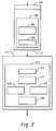
- FIGURE 2 further illustrates the detector array 112 and the signal processing component 114.
- the detector array 112 includes a radiation sensitive photo sensor 204 that detects the radiation traversing the examination region 106.
- the detector array 112 comprises a scintillator 202 and a photo sensor 204.
- a single direct conversion detector could be used to translate x-ray radiation into electrical signals.
- the scintillator 202 is a fast scintillator.
- the scintillator 202 may have a decay time in a range from about zero (0) nanoseconds (ns) to about forty (40) ns with low afterglow.
- the scintillator 202 can generate on the order of between twenty (20) to sixty (60) photons per impingent keV of x-ray event.
- scintillators examples include Lu 3 Al 5 O 12 :Pr (LUAG), LuAlO 3 :Ce (LuAp), Lu 2 SiO 5 :Ce (LSO), Lu 2 Si 2 O 7 :Ce (LPS), LaBr, LaCl based scintillators.
- the illustrated photo sensor 204 is a high quality photodiode or other photo sensor.
- the illustrated photo sensor 204 has a low dark current, a low capacitance, and a high resistivity.
- the illustrated sensor 204 may have a capacitance in a range fifteen (15O pico-farads or less and a resistivity equal to or greater than one Giga-ohm (1 G ⁇ ).
- Photo sensors with different capacitance and/or resistivity characteristics are also contemplated.
- the photon sensor could also be an Avalache Photo Diode (APD) or another photon sensor that includes multiplication of carriers to enlarge the signal.
- APD Avalache Photo Diode
- the detector array 112 also includes an amplifier 206.
- the illustrated amplifier 206 is a wide bandwidth amplifier.
- the illustrated amplifier 206 may be a one Giga-Hertz (1 GHz) or greater amplifier, for example, ten (10) GHz. Amplifiers with narrower bandwidth are also contemplated.
- the photo sensor 204 and the amplifier 206 are located on the same wafer 208.
- the electrical connections between the sensor 204 and the amplifier 206 may be shorter relative to a configuration in which the sensor 204 and the amplifier 206 are located on different wafers.
- the signal-to-noise ratio (SNR) may be higher relative to the configuration in which the sensor 204 and the amplifier 206 are located on different wafers.
- the wafer 208 may be a silicon or other type of wafer.
- the signal processing component 114 includes an Application Specific Integrated Circuit (ASIC) 210.
- the ASIC 210 includes a digitizer 212 such as an analog to digital converter (ADC).
- ADC analog to digital converter
- the digitizer 212 is a fast digital ADC.
- the digitizer 212 may be a one hundred (100) Mega-Hertz (MHz), a 1GHz or a 10 GHz digitizer.
- the ASIC 210 further includes a digital signal analyzer 214.
- the signal analyzer 214 determines whether the ASIC 210 operates in counting mode or in integrating mode.
- the signal analyzer 214 identifies, from the signal from the detector array 112, whether the level of the x-ray flush is such that individual pulses can be counted.
- the signal analyzer 214 uses a feed-forward neural network trained on low x-ray flux and high x-ray fluxes to determine whether individual pulses can be identified. In general, individual pulses can be counted for relatively low fluxes and cannot be counted for relatively high fluxes.
- the ASIC 210 further includes counting electronics 216 and integrating electronics 218.
- the counting electronics 216 energy-bins and counts pulses for each integration period when the signal analyzer 214 determines that individual pulses can be counted.
- the integrating electronics 218 integrates the combined pulses over each integration period when the signal analyzer 214 determines that individual pulses cannot be counted. Alternatively the integrated electronics 218 could be activated to generate the integration value for every integration period. As the integration is digital, digital corrections could be applied to eliminate offset and non-linearities
- the ASIC 210 also includes readout electronics 220.
- the ASIC 210 is a digital ASIC, and both the digitizer 212 and the signal analyzer 214 on located on the ASIC. This may reduce cost relative to using a mixed-signal ASIC, which can be more expensive to manufacture, without the digitizer 212.
- the digitizer could be part of wafer 208 or the amplifier 206 could be part of the ASIC 201.
- the radiation sensitive photo sensor 204 receives the light and generates a signal indicative of the detected radiation.
- the signal may be an electrical signal such as an electrical current or an electrical voltage.
- the amplifier 206 produces a pulse indicative of the energy of the received radiation.
- the pulse may be an electrical current pulse or electrical voltage pulse having peak amplitude that is indicative of the energy of the detected photon.
- the digitizer 212 produces a digitized signal that includes the pulse.
- the signal analyzer 214 receives the digitized signal and determines whether the pulse can be identified in the digitized signal.
- a trained neural network is used in the illustrated embodiment.
- FIGURE 4 and 5 show digitized pulses respectively for relatively lower and higher fluxes.
- a first axis 402 represents the electrical current level
- a second axis 404 represents time.
- the end of the integration period is indicated by reference numeral 406.
- the output of the ASIC 210 may include individual digitized pulses 408 and 410 that can be identified.
- a first axis 502 represents the electrical current level
- a second axis 504 represents time
- the end of the integration period is indicated by reference numeral 506.
- individual pulses cannot be identified in the digitized signal.
- the counting electronics 216 energy bins the digitized pulses, and at 314 the counting electronics 216 counts the digitized pulses. For example, for each digitized pulse 408 and 410 the counting electronics 216 sums the samples in the digitized pulse to compute an approximate total energy of the digitized pulse, and the number of pulses for each different energy are counted and stored for each integration period 406.
- the integrating electronics 218 integrates the digitized signal from the digitizer 212.
- the integrating electronics 218 may sum the samples in the digitized signal 508 over the integration period 506 to generate a total energy for integration period 506. This mode could be activated for every event, regardless of whether it is possible to suitably differentiate individual events.
- the processed signal is read out by the read out electronics 220.
- the ASIC 210 is shown separate from the detector array 112. In another embodiment, the ASIC 210 is part of the detector array 112.
- the digitizer 212, the signal analyzer 214, the counting circuitry 216, the integrating circuitry 218, and the readout electronics 220 are located on the same ASIC 210. However, in another embodiment, at least one of the digitizer 212, the signal analyzer 214, the counting circuitry 216, the integrating circuitry 218, and the readout electronics 220 is located on different integrated circuits.
- the ASIC 210 operates either in counting mode or in integration mode, based on the level of the x-ray flux: In another embodiment, the ASIC 210 operates in a dual mode at relatively lower fluxes in which the ASIC 210 both counts and integrates the digitized signal produced by the digitizer 212.
- the signal analyzer 214 determines whether individual pulses can be identified for the signal produced by the digitizer 212 by identifying a transition from a falling signal level to a rising signal level. For example, the signal analyzer 214 can determine whether such transition crosses a preset threshold level. If the transition crosses the threshold, the signal analyzer 214 determines that individual pulses are identifiable, and if the transition does not cross the threshold, the signal analyzer 214 determines that individual pulses are not identifiable.
- a probabilistic based approach to determining whether individual pulses can be identified for the signal produced by the digitizer 212 is employed. For instance, a correlation based techniques can be used to determine a degree of correlation between the signal produced by the digitizer 212 and individual digitized signals.
- detector 112 comprised of a scintillator 202 and photo sensors 204.
- any detector suited for radiation detection could be used, including direct conversion detectors.
- a time signal can be generated, from the digitized signal, either by leading edge discrimination or constant fraction discrimination.
- This timing signal could be used in coincidences measurement in a PET scanner. Such a detector could be used both in CT and PET scanners.
- the accuracy of the timing signal may also depend on the digitization frequency. A digitization of ten (10) GHz could lead to theoretical accuracy of 200 pas, which is applicable for TOF PET.
Landscapes
- Health & Medical Sciences (AREA)
- Physics & Mathematics (AREA)
- Life Sciences & Earth Sciences (AREA)
- Spectroscopy & Molecular Physics (AREA)
- Molecular Biology (AREA)
- High Energy & Nuclear Physics (AREA)
- General Physics & Mathematics (AREA)
- Biomedical Technology (AREA)
- Optics & Photonics (AREA)
- Nuclear Medicine, Radiotherapy & Molecular Imaging (AREA)
- Medical Informatics (AREA)
- General Health & Medical Sciences (AREA)
- Engineering & Computer Science (AREA)
- Measurement Of Radiation (AREA)
- Apparatus For Radiation Diagnosis (AREA)
Description
- The following relates to a radiation sensitive detector, and finds particular application to computed tomography (CT). However, it also amenable to other medical imaging applications and to non-medical imaging applications.
- A computed tomography (CT) scanner includes an x-ray tube that emits polychromatic radiation that traverses an examination region. A detector array, which subtends an arc on a side of the examination region opposite of the x-ray tube, detects radiation that traverses the examination region. The detector array generates a signal that is indicative of the examination region. A reconstructor reconstructs the signal and generates volumetric image data indicative of the examination region. An image processor processes the volumetric image data to generate one or more images of the examination region.
- With a CT scanner that includes a conventional integrating, or indirect conversion detector, such as a Gadolinium Oxysulfide (GOS) based detector, the resulting image has included pixels represented in terms of grey scale values corresponding to relative radiodensity. Such information reflects the attenuation characteristics of the scanned subject matter and generally shows structure such as anatomical structures within a patient, physical structures within an inanimate object, or the like.
- Unfortunately, the x-ray attenuation through a given object is strongly dependent on the incident x-ray photon energy. This physical phenomenon manifests itself in an image as beam-hardening artifacts, such as, non-uniformity, shading, and streaks. Some beam-hardening artifacts can be easily corrected, but other beam-hardening artifacts may be more difficult to correct. In addition, a highly attenuating material with a low density may result in the same CT number in the image as a less attenuating material with a high density. Thus, there is little or no information about the material composition of a scanned object based solely on the CT number.
- Capturing spectral characteristics of the radiation provides more information, which can be used to mitigate beam hardening artifact and provide information about the material composition of the scanned object. Integrating detectors generally are poorly-suited to count due to a low signal-to-noise ratio (SNR). In contrast, counting direct conversion detectors such as a Cadmium Zinc Telluride (CdZnTe or CZT) or a Cadmium Telluride (CdTe) based detector can capture spectral information, for example, by concurrently counting photons and measuring the energy of the photons.
- However, counting detectors generally are poorly suited for CT applications since such detectors typically are unable to count photons for x-ray fluxes above ten (10) mega-counts per second (Mcounts/sec), and some x-ray tubes can deliver more than 10 Mcounts/sec, for example, counts such as 100 Mcounts/sec. The photon flux can be reduced to a level at which the counting detector electronics can count the photons; however, reducing the photon flux as such can lead to a decrease in the SNR, and, more significantly, to a decrease in the dynamic range that is unacceptable to CT. Moreover, direct conversion counting detectors generally are poorly-suited to integrate due to the high after glow.
- US patent application
US2006/0565676 A1 discloses dynamically controlling the shaping time characteristics of a photon counting detector to accommodate variations of flux experienced by the detector. - Aspects of the present application address the above-referenced matters and others.
- According to one aspect, radiation sensitive detector array includes a photo sensor that detects an x-ray photon and generates a signal indicative thereof. The radiation sensitive detector array also includes a signal analyzer that energy bins and counts the signal when the signal analyzer is able to identify the signal in the output of the photo sensor, and that integrates the output of the photo sensor over an integration period when the signal analyzer is not able to identify the signal in the output of the photo sensor.
- According to another aspect, a medical imaging apparatus includes a radiation source that emits radiation that traverses the examination region and a detector array in accordance with the above first aspect.
- According to another aspect, a method includes determining whether digitized pulses in a digitized signal are identifiable from each other, wherein each digitized pulse corresponds to the energy of a detected x-ray photon from a radiation beam emitted by a medical imaging system. The method further includes energy-resolving the digitized pulses when the digitized pulses are identifiable from each other. The method further includes integrating the digital signal when the digitized pulses are not identifiable from each other.
- The invention may take form in various components and arrangements of components, and in various steps and arrangements of steps. The drawings are only for purposes of illustrating the preferred embodiments and are not to be construed as limiting the invention.
-
FIGURE 1 illustrates a medical imaging apparatus. -
FIGURE 2 illustrates an example detector array and an example signal processing component of the medical imaging apparatus. -
FIGURE 3 illustrates a flow chart. -
FIGURE 4 illustrates digitized pulses for a relatively low x-ray flux. -
FIGURE 5 illustrates digitized pulses for a relatively high x-ray flux. - Initially referring to
FIGURE 1 , a computed tomography (CT)scanner 100 includes astationary gantry 102, which is stationary in the sense that it is generally stationary during scanning. However, thestationary gantry 102 may be configured to tilt and/or otherwise be moved. - The computed tomography (CT)
system 100 also includes arotating gantry 104, which is rotatably coupled to thestationary gantry 102. The rotatinggantry 104 rotates around anexamination region 106 about a longitudinal or z-axis 108. - In the illustrated embodiment, a
radiation source 110, such as an x-ray tube, is supported by and rotates with the rotatinggantry 104 around theexamination region 106. Theradiation source 110 emits polychromatic radiation that traverses theexamination region 106. In another embodiment, theCT system 100 is a stationary scanner with one or more of theradiation sources 110 supported by thestationary gantry 102. - A radiation
sensitive detector array 112 detects photons emitted by theradiation source 110 that traverse theexamination region 106. The radiationsensitive detector array 112 includes multiple rows of radiation sensitive photo sensor that extend in the z-axis direction, and multiple columns of radiation sensitive photo sensors that extend in a traverse direction. A single row detector array configuration is also contemplated. - In the illustrated embodiment, the radiation
sensitive detector array 112 includes a scintillator-based photo sensor such as photodiode in optical communication with a scintillator, and the photo sensor and the signal shaping electronics are located on the same integrated circuit. The radiationsensitive detector array 112 generates an electrical signal, such as electrical currents or voltages, indicative of the detected radiation. In other embodiments, another indirect conversion detector or a direct conversion detector, which directly produces an electrical signal indicative of a detected photon, may be employed. Examples of suitable direct conversion detectors include a CZT, a CdTe, a Lead(II) oxide (PbO), a HgI based detector. - A
signal processor 114 processes the signal generated the radiationsensitive detector array 112. As described in greater detail below, thesignal processor 114 includes electronics that determines whether individual pulses in the signal produced by the radiationsensitive detector array 112 are identifiable based on the shape of the signal. If thesignal processor 114 determines that individual pulses are identifiable, then thesignal processor 114 operates in counting mode and energy resolves (energy bins and counts) the individual pulses for each integration period. If thesignal processor 114 determines that individual pulses are not identifiable, then thesignal processor 114 operates in integrating mode and integrates the total energy of the signal for each integration period. - The
signal processor 114 can also generate a digital timing signal according to a pulse. The timing could be generated as a Leading Edge Discriminator signal, where the signal which is larger than a preset value, or as a Constant Fraction Discrimination, where the signal is a fraction of the maximum of the signal. - A
reconstructor 116 reconstructs projection data from the detectors to generate volumetric data indicative of the interior anatomy of the patient. Animage processor 118 processes the volumetric image data generated by thereconstructor 116 for display in human readable form. - A patient support 120, such as a couch, supports a patient in the
examination region 106. Thepatient support 120 is movable along the z-axis 108 in coordination with the rotation of the rotatinggantry 104 to facilitate helical, axial, or other desired scanning trajectories. - A general
purpose computing system 122 serves as an operator console. Theoperator console 122 includes human readable output devices such as a display and/or printer and input devices such as a keyboard and/or mouse. Software resident on theconsole 122 allows the operator to control the operation of thesystem 100, for example, by allowing the operator to select a scan protocol, initiate scanning, terminate scanning, view and/or manipulate the volumetric image data, and/or otherwise interact with thesystem 100. -
FIGURE 2 further illustrates thedetector array 112 and thesignal processing component 114. Thedetector array 112 includes a radiationsensitive photo sensor 204 that detects the radiation traversing theexamination region 106. Thedetector array 112 comprises ascintillator 202 and aphoto sensor 204. Alternatively a single direct conversion detector could be used to translate x-ray radiation into electrical signals. - In the illustrated example, the
scintillator 202 is a fast scintillator. For instance, thescintillator 202 may have a decay time in a range from about zero (0) nanoseconds (ns) to about forty (40) ns with low afterglow. As such, thescintillator 202 can generate on the order of between twenty (20) to sixty (60) photons per impingent keV of x-ray event. Examples of such scintillators include Lu3Al5O12:Pr (LUAG), LuAlO3:Ce (LuAp), Lu2SiO5:Ce (LSO), Lu2Si2O7:Ce (LPS), LaBr, LaCl based scintillators. - The illustrated
photo sensor 204 is a high quality photodiode or other photo sensor. For example, the illustratedphoto sensor 204 has a low dark current, a low capacitance, and a high resistivity. For instance, the illustratedsensor 204 may have a capacitance in a range fifteen (15O pico-farads or less and a resistivity equal to or greater than one Giga-ohm (1 GΩ). Photo sensors with different capacitance and/or resistivity characteristics are also contemplated. The photon sensor could also be an Avalache Photo Diode (APD) or another photon sensor that includes multiplication of carriers to enlarge the signal. - The
detector array 112 also includes anamplifier 206. The illustratedamplifier 206 is a wide bandwidth amplifier. For example, the illustratedamplifier 206 may be a one Giga-Hertz (1 GHz) or greater amplifier, for example, ten (10) GHz. Amplifiers with narrower bandwidth are also contemplated. - As shown, the
photo sensor 204 and theamplifier 206 are located on thesame wafer 208. As a consequence, the electrical connections between thesensor 204 and theamplifier 206 may be shorter relative to a configuration in which thesensor 204 and theamplifier 206 are located on different wafers. As a result, the signal-to-noise ratio (SNR) may be higher relative to the configuration in which thesensor 204 and theamplifier 206 are located on different wafers. Thewafer 208 may be a silicon or other type of wafer. - The
signal processing component 114 includes an Application Specific Integrated Circuit (ASIC) 210. TheASIC 210 includes adigitizer 212 such as an analog to digital converter (ADC). In the illustrated embodiment, thedigitizer 212 is a fast digital ADC. For instance, thedigitizer 212 may be a one hundred (100) Mega-Hertz (MHz), a 1GHz or a 10 GHz digitizer. - The
ASIC 210 further includes adigital signal analyzer 214. Thesignal analyzer 214 determines whether theASIC 210 operates in counting mode or in integrating mode. Thesignal analyzer 214 identifies, from the signal from thedetector array 112, whether the level of the x-ray flush is such that individual pulses can be counted. In the illustrated embodiment, thesignal analyzer 214 uses a feed-forward neural network trained on low x-ray flux and high x-ray fluxes to determine whether individual pulses can be identified. In general, individual pulses can be counted for relatively low fluxes and cannot be counted for relatively high fluxes. - The
ASIC 210 further includes countingelectronics 216 and integratingelectronics 218. The countingelectronics 216 energy-bins and counts pulses for each integration period when thesignal analyzer 214 determines that individual pulses can be counted. The integratingelectronics 218 integrates the combined pulses over each integration period when thesignal analyzer 214 determines that individual pulses cannot be counted. Alternatively theintegrated electronics 218 could be activated to generate the integration value for every integration period. As the integration is digital, digital corrections could be applied to eliminate offset and non-linearities - The
ASIC 210 also includesreadout electronics 220. - In the illustrated example, the
ASIC 210 is a digital ASIC, and both thedigitizer 212 and thesignal analyzer 214 on located on the ASIC. This may reduce cost relative to using a mixed-signal ASIC, which can be more expensive to manufacture, without thedigitizer 212. In another embodiment, the digitizer could be part ofwafer 208 or theamplifier 206 could be part of the ASIC 201. - Operation is described in connection with
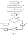
FIGURE 3 . At 302, radiation traversing the examination region strikes thescintillator 202, which produces light indicative of the energy of the radiation. - At 304, the radiation
sensitive photo sensor 204 receives the light and generates a signal indicative of the detected radiation. The signal may be an electrical signal such as an electrical current or an electrical voltage. - At 306, the
amplifier 206 produces a pulse indicative of the energy of the received radiation. The pulse may be an electrical current pulse or electrical voltage pulse having peak amplitude that is indicative of the energy of the detected photon. - At 308, the
digitizer 212 produces a digitized signal that includes the pulse. - At 310, the
signal analyzer 214 receives the digitized signal and determines whether the pulse can be identified in the digitized signal. As noted above, a trained neural network is used in the illustrated embodiment. -
FIGURE 4 and 5 show digitized pulses respectively for relatively lower and higher fluxes. - With respect to
FIGURE 4 , afirst axis 402 represents the electrical current level, and asecond axis 404 represents time. The end of the integration period is indicated byreference numeral 406. As shown inFIGURE 4 , for relatively lower fluxes, the output of theASIC 210 may include individualdigitized pulses - With respect to
FIGURE 5 , afirst axis 502 represents the electrical current level, asecond axis 504 represents time, and the end of the integration period is indicated byreference numeral 506. As shown inFIGURE 5 , for relatively higher fluxes, individual pulses cannot be identified in the digitized signal. - Returning to
FIGURE 3 , if individual digitized pulses are identifiable, then at 312 the countingelectronics 216 energy bins the digitized pulses, and at 314 the countingelectronics 216 counts the digitized pulses. For example, for eachdigitized pulse electronics 216 sums the samples in the digitized pulse to compute an approximate total energy of the digitized pulse, and the number of pulses for each different energy are counted and stored for eachintegration period 406. - Otherwise, at 318 the integrating
electronics 218 integrates the digitized signal from thedigitizer 212. For example, the integratingelectronics 218 may sum the samples in thedigitized signal 508 over theintegration period 506 to generate a total energy forintegration period 506. This mode could be activated for every event, regardless of whether it is possible to suitably differentiate individual events. - At 320, the processed signal is read out by the read out
electronics 220. - Variations are discussed.
- In the illustrated embodiment, the
ASIC 210 is shown separate from thedetector array 112. In another embodiment, theASIC 210 is part of thedetector array 112. - In the above discussed embodiment, the
digitizer 212, thesignal analyzer 214, the countingcircuitry 216, the integratingcircuitry 218, and thereadout electronics 220 are located on thesame ASIC 210. However, in another embodiment, at least one of thedigitizer 212, thesignal analyzer 214, the countingcircuitry 216, the integratingcircuitry 218, and thereadout electronics 220 is located on different integrated circuits. - As described above, the
ASIC 210 operates either in counting mode or in integration mode, based on the level of the x-ray flux: In another embodiment, theASIC 210 operates in a dual mode at relatively lower fluxes in which theASIC 210 both counts and integrates the digitized signal produced by thedigitizer 212. - In another embodiment, the
signal analyzer 214 determines whether individual pulses can be identified for the signal produced by thedigitizer 212 by identifying a transition from a falling signal level to a rising signal level. For example, thesignal analyzer 214 can determine whether such transition crosses a preset threshold level. If the transition crosses the threshold, thesignal analyzer 214 determines that individual pulses are identifiable, and if the transition does not cross the threshold, thesignal analyzer 214 determines that individual pulses are not identifiable. - In another embodiment, a probabilistic based approach to determining whether individual pulses can be identified for the signal produced by the
digitizer 212 is employed. For instance, a correlation based techniques can be used to determine a degree of correlation between the signal produced by thedigitizer 212 and individual digitized signals. - The embodiments herein were described in connection with a computed tomography medical imaging applications. However, it is to be understood that the invention may additionally or alternatively be employed with other medical imaging applications and/or non-medical imaging applications in which it is desirable to capture spectral aspects of radiation.
- The embodiments herein were described with a
detector 112 comprised of ascintillator 202 andphoto sensors 204. However it is to be understood that any detector suited for radiation detection could be used, including direct conversion detectors. - In the case that individual pulses can be identified, a time signal can be generated, from the digitized signal, either by leading edge discrimination or constant fraction discrimination. This timing signal could be used in coincidences measurement in a PET scanner. Such a detector could be used both in CT and PET scanners. The accuracy of the timing signal may also depend on the digitization frequency. A digitization of ten (10) GHz could lead to theoretical accuracy of 200 pas, which is applicable for TOF PET.
- The invention has been described with reference to the preferred embodiments. Modifications and alterations may occur to others upon reading and understanding the preceding detailed description. It is intended that the invention be constructed as including all such modifications and alterations insofar as they come within the scope of the appended claims.
Claims (15)
- A radiation sensitive detector array (112), comprising:a photo sensor (204) that is configured to detect an x-ray photon and to generate a signal indicative thereof;a signal processor (114) configured to determine whether individual pulses of the signal in the output of the photo sensor (204) are identifiable or not identifiable;a signal analyzer (214) that is configured to energy bin and count the signal, characterized in that the signal analyzer (214) is also configured to integrate the signal, wherein the signal analyzer (214) is configured to energy bin and count the signal when the individual pulses are determined by the signal processor (114) to be identifiable, and that the signal analyzer (214) is configured to integrate the output of the photo sensor (204) over an integration period when the individual pulses are determined by the signal processor (114) to be not identifiable.
- The radiation sensitive detector array of claim 1, further including:electronics (206) that receives the signal and produces an output that includes a pulse indicative of the energy of the detected photon, wherein the signal analyzer (214) energy bins and counts the pulse when the signal analyzer (214) is able to identify the pulse in the output of the electronics (206), and that integrates the output of the electronics (206) over the integration period when the signal analyzer (214) is not able to identify the pulse in the output of the electronics (206); anda wafer (208), wherein both the photo sensor (204) and the electronics (206) are located on the wafer (208).
- The radiation sensitive detector array of claim 1, further including a digitizer (212) that digitizes the output of the photo sensor (204), wherein the signal analyzer (214) analyzes the digitized output to determine whether the individual pulses in the signal are identifiable in the digitized output.
- The radiation sensitive detector array of claim 3, wherein the signal analyzer (214) employs a neural network to determine whether the individual pulses in the signal are identifiable in the digitized output, wherein the neural network is trained with data including digital pulses corresponding to low x-ray fluxes and digital pulses corresponding to high x-ray fluxes.
- The radiation sensitive detector array of claim 3, further including a digital ASIC (210), wherein both the digitizer (212) and the signal analyzer (214) are located on the digital ASIC (210).
- The radiation sensitive detector array of claim 1, wherein the radiation sensitive detector array (112) operates in a photon counting mode when an x-ray flux corresponding to the detected photons is equal to or less than 10 Mega-counts per seconds, and the radiation sensitive detector array (112) operates in an integrating mode when the x-ray flux corresponding to the detected photons is greater than 10 Mega-counts per seconds.
- A medical imaging apparatus, comprising:a radiation source (110) that emits radiation that traverses the examination region (106); anda radiation sensitive detector array (112) according to any of the claims 1 to 6.
- The medical imaging apparatus of claim 7, wherein the radiation sensitive detector array (112) integrates the digitized output when the x-ray flux of the detected radiation is relatively high, and the radiation sensitive detector array (112) energy-bins and counts the pulse in the digitized output when the x-ray flux of the detected radiation is relatively low.
- A method, comprising:determining whether digitized pulses in a digitized signal are identifiable from each other, wherein each digitized pulse corresponds to the energy of a detected x-ray photon from a radiation beam emitted by a medical imaging system (100);energy-resolving the digitized pulses when the digitized pulses are identifiable from each other; andintegrating the digital signal when the digitized pulses are not identifiable from each other.
- The method of claim 9, further including integrating the digital signal when the digitized pulses are identifiable from each other.
- The method of claim 9, further including digitizing a signal from a radiation sensitive detector (112) detecting the radiation beam to generate at least one of the digitized pulses.
- The method of claim 9, further including employing a neural network to determine whether the digitized pulses are identifiable from each other.
- The method of claim 9, further including generating a time signal from the digitized signal.
- The method of claim 13, wherein the time signal is generated by one of leading edge discrimination or constant fraction discrimination.
- The method of claim 9, further including both energy-resolving the digitized pulses and integrating the digital signal when the digitized pulses are identifiable from each other.
Applications Claiming Priority (2)
| Application Number | Priority Date | Filing Date | Title |
|---|---|---|---|
| US1520707P | 2007-12-20 | 2007-12-20 | |
| PCT/IB2008/055259 WO2009083847A2 (en) | 2007-12-20 | 2008-12-12 | Counting integrating detector |
Publications (2)
| Publication Number | Publication Date |
|---|---|
| EP2225587A2 EP2225587A2 (en) | 2010-09-08 |
| EP2225587B1 true EP2225587B1 (en) | 2016-03-16 |
Family
ID=40824799
Family Applications (1)
| Application Number | Title | Priority Date | Filing Date |
|---|---|---|---|
| EP08867897.4A Active EP2225587B1 (en) | 2007-12-20 | 2008-12-12 | Radiation detector for counting or integrating signals |
Country Status (6)
| Country | Link |
|---|---|
| US (1) | US8299440B2 (en) |
| EP (1) | EP2225587B1 (en) |
| JP (1) | JP5670739B2 (en) |
| CN (1) | CN101903799A (en) |
| RU (1) | RU2489733C2 (en) |
| WO (1) | WO2009083847A2 (en) |
Families Citing this family (26)
| Publication number | Priority date | Publication date | Assignee | Title |
|---|---|---|---|---|
| EP2513670B1 (en) * | 2009-12-15 | 2020-02-05 | Saint-Gobain Ceramics & Plastics, Inc. | Radiation detection system and method of analyzing an electrical pulse output by a radiation detector |
| US8963093B2 (en) * | 2010-10-09 | 2015-02-24 | Fmi Technologies, Inc. | Tomographic imaging methods and systems for digital wave front decimation in time sampling |
| GB201019521D0 (en) | 2010-11-18 | 2010-12-29 | Durham Scient Crystals Ltd | Radiation detection |
| DE102011076351A1 (en) * | 2011-05-24 | 2012-08-09 | Siemens Aktiengesellschaft | Method for producing tomographic image data sets of patient, involves correcting energy resolution measurement with respect to measurement object radiations, and reconstructing data set from corrected measurement |
| CN103181769A (en) * | 2011-10-09 | 2013-07-03 | 明峰医疗系统股份有限公司 | Tomography method and system sued for sample-separation real-time sampling of leading edges of digital waves |
| WO2014126189A1 (en) * | 2013-02-14 | 2014-08-21 | 株式会社テレシステムズ | X-ray imaging device and x-ray imaging method |
| CN105073010B (en) * | 2013-04-04 | 2018-04-03 | 东芝医疗系统株式会社 | X-ray computed tomograohy apparatus |
| US9748300B2 (en) * | 2013-09-05 | 2017-08-29 | Koninklijke Philips N.V. | Radiation detector element |
| JP2015180859A (en) * | 2014-03-05 | 2015-10-15 | 株式会社東芝 | photon counting CT apparatus |
| US9897707B2 (en) * | 2014-06-20 | 2018-02-20 | Bruker Axs, Inc. | X-ray detector operable in a mixed photon-counting/analog output mode |
| CN105662448B (en) * | 2014-11-21 | 2021-06-22 | Ge医疗系统环球技术有限公司 | Data detection and acquisition system for CT machine |
| KR101725099B1 (en) * | 2014-12-05 | 2017-04-26 | 삼성전자주식회사 | Computed tomography apparatus and control method for the same |
| US9606245B1 (en) | 2015-03-24 | 2017-03-28 | The Research Foundation For The State University Of New York | Autonomous gamma, X-ray, and particle detector |
| EP3374803B1 (en) * | 2015-11-12 | 2020-04-01 | Prismatic Sensors AB | High-resolution computed tomography using edge-on detectors with temporally offset depth-segments |
| US10571579B2 (en) * | 2016-01-22 | 2020-02-25 | General Electric Company | Dual-mode radiation detector |
| CN109863512B (en) * | 2016-09-01 | 2023-10-20 | 通用医疗公司 | System and method for automatic transformation by manifold approximation |
| US10107921B1 (en) * | 2016-09-08 | 2018-10-23 | Koninklijke Philips N.V. | Radiation detector and X-ray imaging system |
| WO2018090163A1 (en) * | 2016-11-15 | 2018-05-24 | Shenzhen Xpectvision Technology Co., Ltd. | An image sensor |
| CN106596597B (en) * | 2016-12-08 | 2019-10-11 | 同方威视技术股份有限公司 | Radiation detector assembly, method and data processing method and processor |
| US20200158891A1 (en) * | 2017-05-10 | 2020-05-21 | The Texas A&M University System | Low-Power Multi-Channel Analyzer for Portable Radiation Systems |
| WO2019144344A1 (en) * | 2018-01-25 | 2019-08-01 | Shenzhen Xpectvision Technology Co., Ltd. | Radiation detector with quantum dot scintillator |
| KR102051576B1 (en) * | 2018-03-07 | 2019-12-05 | 한국과학기술원 | Apparatus and method for identifying multi-radioisotope based on plastic scintillator using Artificial Neural Network |
| WO2020047839A1 (en) * | 2018-09-07 | 2020-03-12 | Shenzhen Xpectvision Technology Co., Ltd. | A radiation detector |
| CN110037718B (en) * | 2019-04-24 | 2022-11-25 | 上海联影医疗科技股份有限公司 | Hardware state analysis method and device, computer equipment and storage medium |
| WO2021075345A1 (en) * | 2019-10-18 | 2021-04-22 | 株式会社堀場製作所 | Signal processing method, learning model generation method, signal processing device, radiation detection device, and computer program |
| CN110687583B (en) * | 2019-11-05 | 2021-04-13 | 中国计量科学研究院 | Position energy time testing system and device based on CZT detector |
Family Cites Families (14)
| Publication number | Priority date | Publication date | Assignee | Title |
|---|---|---|---|---|
| US7020A (en) * | 1850-01-15 | Improvement in harvesting-mac mines | ||
| JPS5835481A (en) * | 1981-08-28 | 1983-03-02 | Toshiba Corp | Measuring device for radiation |
| JPS61226675A (en) * | 1985-03-30 | 1986-10-08 | Toshiba Corp | Radioactive ray measuring instrument |
| US4893015A (en) * | 1987-04-01 | 1990-01-09 | American Science And Engineering, Inc. | Dual mode radiographic measurement method and device |
| RU2098799C1 (en) * | 1994-03-10 | 1997-12-10 | Институт теоретической и экспериментальной физики | Method of gamma-stereoscopy |
| US5689115A (en) * | 1995-11-24 | 1997-11-18 | Elscint Ltd. | Advanced nuclear medicine system |
| US5910109A (en) * | 1997-02-20 | 1999-06-08 | Emerging Technology Systems, Llc | Non-invasive glucose measuring device and method for measuring blood glucose |
| EP1257847A1 (en) * | 1999-10-08 | 2002-11-20 | Mamea Imaging AB | Method and arrangement relating to x-ray imaging |
| FR2803916B1 (en) * | 2000-01-18 | 2002-04-19 | Biospace Instr | METHOD AND DEVICE FOR IONIZING RADIATION IMAGING |
| JP3824264B2 (en) * | 2002-03-20 | 2006-09-20 | 株式会社日立製作所 | Radiation inspection apparatus and radiation detection method |
| EP1706884A2 (en) * | 2003-12-30 | 2006-10-04 | DxRay, Inc. | Pixelated cadmium zinc telluride based photon counting mode detector |
| US7105828B2 (en) * | 2004-02-10 | 2006-09-12 | Ge Medical Systems Global Technology Company, Llc | Hybrid x-ray detector |
| US7149278B2 (en) * | 2004-09-10 | 2006-12-12 | General Electric Company | Method and system of dynamically controlling shaping time of a photon counting energy-sensitive radiation detector to accommodate variations in incident radiation flux levels |
| US7332724B2 (en) * | 2005-07-26 | 2008-02-19 | General Electric Company | Method and apparatus for acquiring radiation data |
-
2008
- 2008-12-12 RU RU2010130183/28A patent/RU2489733C2/en not_active IP Right Cessation
- 2008-12-12 JP JP2010538989A patent/JP5670739B2/en active Active
- 2008-12-12 US US12/746,332 patent/US8299440B2/en active Active
- 2008-12-12 WO PCT/IB2008/055259 patent/WO2009083847A2/en active Application Filing
- 2008-12-12 EP EP08867897.4A patent/EP2225587B1/en active Active
- 2008-12-12 CN CN2008801213987A patent/CN101903799A/en active Pending
Also Published As
| Publication number | Publication date |
|---|---|
| US20100246919A1 (en) | 2010-09-30 |
| WO2009083847A3 (en) | 2009-12-30 |
| JP2011508201A (en) | 2011-03-10 |
| EP2225587A2 (en) | 2010-09-08 |
| CN101903799A (en) | 2010-12-01 |
| RU2010130183A (en) | 2012-01-27 |
| JP5670739B2 (en) | 2015-02-18 |
| US8299440B2 (en) | 2012-10-30 |
| WO2009083847A2 (en) | 2009-07-09 |
| RU2489733C2 (en) | 2013-08-10 |
Similar Documents
| Publication | Publication Date | Title |
|---|---|---|
| EP2225587B1 (en) | Radiation detector for counting or integrating signals | |
| US9678220B2 (en) | X-ray detector with saturated sensor element estimated photon counting | |
| US7480362B2 (en) | Method and apparatus for spectral computed tomography | |
| EP2052279B1 (en) | Apparatus and method for spectral computed tomography | |
| US7512210B2 (en) | Hybrid energy discriminating charge integrating CT detector | |
| JP4904349B2 (en) | Detector and system for acquiring radiation data | |
| US7696483B2 (en) | High DQE photon counting detector using statistical recovery of pile-up events | |
| RU2594606C2 (en) | Photon counting detector | |
| US7894576B2 (en) | Spectral computed tomography using correlated photon number and energy measurements | |
| US9000385B2 (en) | Method and apparatus for acquiring radiation data | |
| US20090304149A1 (en) | X-ray detector imaging with polychromatic spectra | |
| US10357214B2 (en) | Photon counting CT apparatus, light detection device, radiation detection device, and radiation analysis device | |
| WO2008146230A2 (en) | Photon counting with detection of local maxima | |
| US20160206255A1 (en) | Hybrid passive/active multi-layer energy discriminating photon-counting detector | |
| CN111656224B (en) | Radiation detector with quantum dot scintillator | |
| JP2015152356A (en) | Dark countless radiation detection energy discrimination imaging system | |
| Barber et al. | Photon counting systems for breast imaging | |
| JP2024020148A (en) | Systems and methods for computed tomography |
Legal Events
| Date | Code | Title | Description |
|---|---|---|---|
| PUAI | Public reference made under article 153(3) epc to a published international application that has entered the european phase |
Free format text: ORIGINAL CODE: 0009012 |
|
| 17P | Request for examination filed |
Effective date: 20100720 |
|
| AK | Designated contracting states |
Kind code of ref document: A2 Designated state(s): AT BE BG CH CY CZ DE DK EE ES FI FR GB GR HR HU IE IS IT LI LT LU LV MC MT NL NO PL PT RO SE SI SK TR |
|
| AX | Request for extension of the european patent |
Extension state: AL BA MK RS |
|
| DAX | Request for extension of the european patent (deleted) | ||
| RAP1 | Party data changed (applicant data changed or rights of an application transferred) |
Owner name: KONINKLIJKE PHILIPS N.V. |
|
| 17Q | First examination report despatched |
Effective date: 20140822 |
|
| GRAP | Despatch of communication of intention to grant a patent |
Free format text: ORIGINAL CODE: EPIDOSNIGR1 |
|
| INTG | Intention to grant announced |
Effective date: 20150915 |
|
| GRAS | Grant fee paid |
Free format text: ORIGINAL CODE: EPIDOSNIGR3 |
|
| GRAA | (expected) grant |
Free format text: ORIGINAL CODE: 0009210 |
|
| AK | Designated contracting states |
Kind code of ref document: B1 Designated state(s): AT BE BG CH CY CZ DE DK EE ES FI FR GB GR HR HU IE IS IT LI LT LU LV MC MT NL NO PL PT RO SE SI SK TR |
|
| REG | Reference to a national code |
Ref country code: GB Ref legal event code: FG4D |
|
| REG | Reference to a national code |
Ref country code: CH Ref legal event code: EP |
|
| REG | Reference to a national code |
Ref country code: IE Ref legal event code: FG4D |
|
| REG | Reference to a national code |
Ref country code: AT Ref legal event code: REF Ref document number: 781712 Country of ref document: AT Kind code of ref document: T Effective date: 20160415 |
|
| REG | Reference to a national code |
Ref country code: DE Ref legal event code: R096 Ref document number: 602008042963 Country of ref document: DE |
|
| REG | Reference to a national code |
Ref country code: DE Ref legal event code: R084 Ref document number: 602008042963 Country of ref document: DE |
|
| REG | Reference to a national code |
Ref country code: NL Ref legal event code: MP Effective date: 20160316 |
|
| REG | Reference to a national code |
Ref country code: LT Ref legal event code: MG4D |
|
| PG25 | Lapsed in a contracting state [announced via postgrant information from national office to epo] |
Ref country code: NO Free format text: LAPSE BECAUSE OF FAILURE TO SUBMIT A TRANSLATION OF THE DESCRIPTION OR TO PAY THE FEE WITHIN THE PRESCRIBED TIME-LIMIT Effective date: 20160616 Ref country code: GR Free format text: LAPSE BECAUSE OF FAILURE TO SUBMIT A TRANSLATION OF THE DESCRIPTION OR TO PAY THE FEE WITHIN THE PRESCRIBED TIME-LIMIT Effective date: 20160617 Ref country code: FI Free format text: LAPSE BECAUSE OF FAILURE TO SUBMIT A TRANSLATION OF THE DESCRIPTION OR TO PAY THE FEE WITHIN THE PRESCRIBED TIME-LIMIT Effective date: 20160316 Ref country code: HR Free format text: LAPSE BECAUSE OF FAILURE TO SUBMIT A TRANSLATION OF THE DESCRIPTION OR TO PAY THE FEE WITHIN THE PRESCRIBED TIME-LIMIT Effective date: 20160316 |
|
| REG | Reference to a national code |
Ref country code: AT Ref legal event code: MK05 Ref document number: 781712 Country of ref document: AT Kind code of ref document: T Effective date: 20160316 |
|
| PG25 | Lapsed in a contracting state [announced via postgrant information from national office to epo] |
Ref country code: NL Free format text: LAPSE BECAUSE OF FAILURE TO SUBMIT A TRANSLATION OF THE DESCRIPTION OR TO PAY THE FEE WITHIN THE PRESCRIBED TIME-LIMIT Effective date: 20160316 Ref country code: LT Free format text: LAPSE BECAUSE OF FAILURE TO SUBMIT A TRANSLATION OF THE DESCRIPTION OR TO PAY THE FEE WITHIN THE PRESCRIBED TIME-LIMIT Effective date: 20160316 Ref country code: LV Free format text: LAPSE BECAUSE OF FAILURE TO SUBMIT A TRANSLATION OF THE DESCRIPTION OR TO PAY THE FEE WITHIN THE PRESCRIBED TIME-LIMIT Effective date: 20160316 Ref country code: SE Free format text: LAPSE BECAUSE OF FAILURE TO SUBMIT A TRANSLATION OF THE DESCRIPTION OR TO PAY THE FEE WITHIN THE PRESCRIBED TIME-LIMIT Effective date: 20160316 |
|
| PG25 | Lapsed in a contracting state [announced via postgrant information from national office to epo] |
Ref country code: EE Free format text: LAPSE BECAUSE OF FAILURE TO SUBMIT A TRANSLATION OF THE DESCRIPTION OR TO PAY THE FEE WITHIN THE PRESCRIBED TIME-LIMIT Effective date: 20160316 Ref country code: PL Free format text: LAPSE BECAUSE OF FAILURE TO SUBMIT A TRANSLATION OF THE DESCRIPTION OR TO PAY THE FEE WITHIN THE PRESCRIBED TIME-LIMIT Effective date: 20160316 Ref country code: IS Free format text: LAPSE BECAUSE OF FAILURE TO SUBMIT A TRANSLATION OF THE DESCRIPTION OR TO PAY THE FEE WITHIN THE PRESCRIBED TIME-LIMIT Effective date: 20160716 |
|
| PG25 | Lapsed in a contracting state [announced via postgrant information from national office to epo] |
Ref country code: PT Free format text: LAPSE BECAUSE OF FAILURE TO SUBMIT A TRANSLATION OF THE DESCRIPTION OR TO PAY THE FEE WITHIN THE PRESCRIBED TIME-LIMIT Effective date: 20160718 Ref country code: SK Free format text: LAPSE BECAUSE OF FAILURE TO SUBMIT A TRANSLATION OF THE DESCRIPTION OR TO PAY THE FEE WITHIN THE PRESCRIBED TIME-LIMIT Effective date: 20160316 Ref country code: CZ Free format text: LAPSE BECAUSE OF FAILURE TO SUBMIT A TRANSLATION OF THE DESCRIPTION OR TO PAY THE FEE WITHIN THE PRESCRIBED TIME-LIMIT Effective date: 20160316 Ref country code: ES Free format text: LAPSE BECAUSE OF FAILURE TO SUBMIT A TRANSLATION OF THE DESCRIPTION OR TO PAY THE FEE WITHIN THE PRESCRIBED TIME-LIMIT Effective date: 20160316 Ref country code: AT Free format text: LAPSE BECAUSE OF FAILURE TO SUBMIT A TRANSLATION OF THE DESCRIPTION OR TO PAY THE FEE WITHIN THE PRESCRIBED TIME-LIMIT Effective date: 20160316 Ref country code: RO Free format text: LAPSE BECAUSE OF FAILURE TO SUBMIT A TRANSLATION OF THE DESCRIPTION OR TO PAY THE FEE WITHIN THE PRESCRIBED TIME-LIMIT Effective date: 20160316 |
|
| REG | Reference to a national code |
Ref country code: DE Ref legal event code: R097 Ref document number: 602008042963 Country of ref document: DE |
|
| REG | Reference to a national code |
Ref country code: FR Ref legal event code: PLFP Year of fee payment: 9 |
|
| PG25 | Lapsed in a contracting state [announced via postgrant information from national office to epo] |
Ref country code: BE Free format text: LAPSE BECAUSE OF FAILURE TO SUBMIT A TRANSLATION OF THE DESCRIPTION OR TO PAY THE FEE WITHIN THE PRESCRIBED TIME-LIMIT Effective date: 20160316 Ref country code: IT Free format text: LAPSE BECAUSE OF FAILURE TO SUBMIT A TRANSLATION OF THE DESCRIPTION OR TO PAY THE FEE WITHIN THE PRESCRIBED TIME-LIMIT Effective date: 20160316 |
|
| PLBE | No opposition filed within time limit |
Free format text: ORIGINAL CODE: 0009261 |
|
| STAA | Information on the status of an ep patent application or granted ep patent |
Free format text: STATUS: NO OPPOSITION FILED WITHIN TIME LIMIT |
|
| PG25 | Lapsed in a contracting state [announced via postgrant information from national office to epo] |
Ref country code: DK Free format text: LAPSE BECAUSE OF FAILURE TO SUBMIT A TRANSLATION OF THE DESCRIPTION OR TO PAY THE FEE WITHIN THE PRESCRIBED TIME-LIMIT Effective date: 20160316 |
|
| 26N | No opposition filed |
Effective date: 20161219 |
|
| PG25 | Lapsed in a contracting state [announced via postgrant information from national office to epo] |
Ref country code: BG Free format text: LAPSE BECAUSE OF FAILURE TO SUBMIT A TRANSLATION OF THE DESCRIPTION OR TO PAY THE FEE WITHIN THE PRESCRIBED TIME-LIMIT Effective date: 20160616 |
|
| PGFP | Annual fee paid to national office [announced via postgrant information from national office to epo] |
Ref country code: FR Payment date: 20161229 Year of fee payment: 9 |
|
| PG25 | Lapsed in a contracting state [announced via postgrant information from national office to epo] |
Ref country code: SI Free format text: LAPSE BECAUSE OF FAILURE TO SUBMIT A TRANSLATION OF THE DESCRIPTION OR TO PAY THE FEE WITHIN THE PRESCRIBED TIME-LIMIT Effective date: 20160316 |
|
| REG | Reference to a national code |
Ref country code: CH Ref legal event code: PL |
|
| GBPC | Gb: european patent ceased through non-payment of renewal fee |
Effective date: 20161212 |
|
| PG25 | Lapsed in a contracting state [announced via postgrant information from national office to epo] |
Ref country code: MC Free format text: LAPSE BECAUSE OF FAILURE TO SUBMIT A TRANSLATION OF THE DESCRIPTION OR TO PAY THE FEE WITHIN THE PRESCRIBED TIME-LIMIT Effective date: 20160316 |
|
| REG | Reference to a national code |
Ref country code: IE Ref legal event code: MM4A |
|
| PG25 | Lapsed in a contracting state [announced via postgrant information from national office to epo] |
Ref country code: CH Free format text: LAPSE BECAUSE OF NON-PAYMENT OF DUE FEES Effective date: 20161231 Ref country code: LI Free format text: LAPSE BECAUSE OF NON-PAYMENT OF DUE FEES Effective date: 20161231 Ref country code: LU Free format text: LAPSE BECAUSE OF NON-PAYMENT OF DUE FEES Effective date: 20161212 |
|
| PG25 | Lapsed in a contracting state [announced via postgrant information from national office to epo] |
Ref country code: GB Free format text: LAPSE BECAUSE OF NON-PAYMENT OF DUE FEES Effective date: 20161212 Ref country code: IE Free format text: LAPSE BECAUSE OF NON-PAYMENT OF DUE FEES Effective date: 20161212 |
|
| PG25 | Lapsed in a contracting state [announced via postgrant information from national office to epo] |
Ref country code: CY Free format text: LAPSE BECAUSE OF FAILURE TO SUBMIT A TRANSLATION OF THE DESCRIPTION OR TO PAY THE FEE WITHIN THE PRESCRIBED TIME-LIMIT Effective date: 20160316 Ref country code: HU Free format text: LAPSE BECAUSE OF FAILURE TO SUBMIT A TRANSLATION OF THE DESCRIPTION OR TO PAY THE FEE WITHIN THE PRESCRIBED TIME-LIMIT; INVALID AB INITIO Effective date: 20081212 |
|
| PG25 | Lapsed in a contracting state [announced via postgrant information from national office to epo] |
Ref country code: TR Free format text: LAPSE BECAUSE OF FAILURE TO SUBMIT A TRANSLATION OF THE DESCRIPTION OR TO PAY THE FEE WITHIN THE PRESCRIBED TIME-LIMIT Effective date: 20160316 |
|
| PG25 | Lapsed in a contracting state [announced via postgrant information from national office to epo] |
Ref country code: MT Free format text: LAPSE BECAUSE OF NON-PAYMENT OF DUE FEES Effective date: 20161212 |
|
| REG | Reference to a national code |
Ref country code: FR Ref legal event code: ST Effective date: 20180831 |
|
| PG25 | Lapsed in a contracting state [announced via postgrant information from national office to epo] |
Ref country code: FR Free format text: LAPSE BECAUSE OF NON-PAYMENT OF DUE FEES Effective date: 20180102 |
|
| PGFP | Annual fee paid to national office [announced via postgrant information from national office to epo] |
Ref country code: DE Payment date: 20231227 Year of fee payment: 16 |