EP3028593A1 - Buckle and seatbelt device with same - Google Patents
Buckle and seatbelt device with same Download PDFInfo
- Publication number
- EP3028593A1 EP3028593A1 EP14831159.0A EP14831159A EP3028593A1 EP 3028593 A1 EP3028593 A1 EP 3028593A1 EP 14831159 A EP14831159 A EP 14831159A EP 3028593 A1 EP3028593 A1 EP 3028593A1
- Authority
- EP
- European Patent Office
- Prior art keywords
- latch
- buckle
- slider
- tongue
- contact
- Prior art date
- Legal status (The legal status is an assumption and is not a legal conclusion. Google has not performed a legal analysis and makes no representation as to the accuracy of the status listed.)
- Granted
Links
- 239000002184 metal Substances 0.000 description 8
- 239000011347 resin Substances 0.000 description 7
- 229920005989 resin Polymers 0.000 description 7
- 230000005489 elastic deformation Effects 0.000 description 3
- 230000006835 compression Effects 0.000 description 1
- 238000007906 compression Methods 0.000 description 1
- 230000000694 effects Effects 0.000 description 1
- 238000003780 insertion Methods 0.000 description 1
- 230000037431 insertion Effects 0.000 description 1
- 238000012986 modification Methods 0.000 description 1
- 230000004048 modification Effects 0.000 description 1
Images


Classifications
-
- A—HUMAN NECESSITIES
- A44—HABERDASHERY; JEWELLERY
- A44B—BUTTONS, PINS, BUCKLES, SLIDE FASTENERS, OR THE LIKE
- A44B11/00—Buckles; Similar fasteners for interconnecting straps or the like, e.g. for safety belts
- A44B11/25—Buckles; Similar fasteners for interconnecting straps or the like, e.g. for safety belts with two or more separable parts
- A44B11/2503—Safety buckles
- A44B11/2546—Details
-
- A—HUMAN NECESSITIES
- A44—HABERDASHERY; JEWELLERY
- A44B—BUTTONS, PINS, BUCKLES, SLIDE FASTENERS, OR THE LIKE
- A44B11/00—Buckles; Similar fasteners for interconnecting straps or the like, e.g. for safety belts
- A44B11/25—Buckles; Similar fasteners for interconnecting straps or the like, e.g. for safety belts with two or more separable parts
- A44B11/2503—Safety buckles
- A44B11/2507—Safety buckles actuated by a push-button
- A44B11/2515—Safety buckles actuated by a push-button acting parallel to the main plane of the buckle and perpendicularly to the direction of the fastening action
-
- A—HUMAN NECESSITIES
- A44—HABERDASHERY; JEWELLERY
- A44B—BUTTONS, PINS, BUCKLES, SLIDE FASTENERS, OR THE LIKE
- A44B11/00—Buckles; Similar fasteners for interconnecting straps or the like, e.g. for safety belts
- A44B11/25—Buckles; Similar fasteners for interconnecting straps or the like, e.g. for safety belts with two or more separable parts
- A44B11/2503—Safety buckles
- A44B11/2546—Details
- A44B11/2561—Tongue elements
-
- B—PERFORMING OPERATIONS; TRANSPORTING
- B60—VEHICLES IN GENERAL
- B60R—VEHICLES, VEHICLE FITTINGS, OR VEHICLE PARTS, NOT OTHERWISE PROVIDED FOR
- B60R22/00—Safety belts or body harnesses in vehicles
- B60R22/18—Anchoring devices
-
- B—PERFORMING OPERATIONS; TRANSPORTING
- B60—VEHICLES IN GENERAL
- B60R—VEHICLES, VEHICLE FITTINGS, OR VEHICLE PARTS, NOT OTHERWISE PROVIDED FOR
- B60R22/00—Safety belts or body harnesses in vehicles
- B60R22/18—Anchoring devices
- B60R2022/1806—Anchoring devices for buckles
Definitions
- the present invention belongs to a technical field of a buckle used in a seat belt apparatus attached to a seat of a vehicle such as an automobile, and a technical field of a seat belt apparatus including the buckle.
- a seat belt apparatus is attached to a seat of various transport facilities including automobiles in order to hold an occupant and reduce inertial motion of the occupant when a vehicle is in an emergency situation such as a collision. In the emergency situation, the vehicle is largely slowed down compared with in a normal traveling situation.
- a seat belt apparatus typically includes a tongue supported by a seat belt and a buckle fixed to a chassis. The tongue is configured to be inserted into the buckle and engage therewith.
- Widely-known buckles used in conventional seat belt apparatus at least include a latch configured to enter an engaging hole of a tongue so as to engage with the tongue inserted into the buckle, a latch retainer configured to be moved by a biasing force of a spring so as to lock the latch in a locking position of the tongue during an engagement operation of the tongue with the latch, an unlocking operation member configured to unlock the latch locked by the latch retainer and remove the latch from the engaging hole of the tongue to disengage the latch from the tongue, and an ejector configured to push the tongue disengaged from the latch by the unlocking operation member in a direction in which the tongue is removed from the buckle.
- a latch configured to enter an engaging hole of a tongue so as to engage with the tongue inserted into the buckle
- a latch retainer configured to be moved by a biasing force of a spring so as to lock the latch in a locking position of the tongue during an engagement operation of the tongue with the latch
- an unlocking operation member configured to unlock the latch locked by the latch retainer and remove the latch from the
- a seat belt apparatus including such a buckle
- the tongue when the occupant wears the seat belt, the tongue is inserted into the buckle, and the latch engages with the tongue.
- the tongue engages with the buckle.
- the seat belt is fastened to the occupant such that the occupant is held by the seat belt in the event of an emergency as described above. This reduces the inertial movement of the occupant.
- the occupant pushes the unlocking operation member to release the seat belt from the occupant.
- the latch is disengaged from the tongue.
- the latch retainer In conventional buckles, the latch retainer is typically moved by a biasing force of a spring during the engagement operation of the tongue with the latch.
- the latch retainer comes in contact with a different component of the tongue, which is unmovable at least in a movement direction of the latch retainer in the operation, and stops. The contact between the latch retainer and the different component of the buckle generates a noise.
- Patent Literature 1 discloses a buckle in which the metal retainer stops when the retainer comes in contact with a stop disposed on a resin release button, which is the unlocking operation member. The contact between the metal component and the resin component generates less noise when the buckle engages with the tongue than the contact between the metal components.
- Patent Literature 1 Although the buckle described in Patent Literature 1 has less noise due to the contact between the metal component and the resin component, as long as the retainer comes in contact with the release button, the noise is generated by impact of the contact. Thus, it is difficult to effectively reduce the noise to be generated when the buckle engages with the tongue. The generation of the noise needs to be more effectively reduced to further improve comfortability of the occupant during seat belt handling.
- the present invention was made in view of the above-described problem. It is an object of the present invention to provide a buckle in which a noise is less generated during an engagement operation of the tongue with the buckle, and a seat belt apparatus including such a buckle. Solution to Problem
- a buckle of the present invention is characterized by at least including a base, a tongue inlet through which an engaging portion of a tongue is inserted, a latch supported by the base so as to move between a non-engaging position at which the latch does not engage with the engaging portion of the tongue inserted through the tongue inlet and an engaging position at which the latch engages with the engaging portion of the tongue inserted through the tongue inlet, a latch retainer configured to be held in a non-locking position at which the latch retainer does not lock the latch positioned in the non-engaging position and configured to move from the non-locking position during operation of the latch and come in contact with a stop so as to be held in a locking position at which the latch retainer locks the latch positioned in the engaging position, and an unlocking operation member configured to move the latch positioned in the engaging position to the non-engaging position, wherein an impact absorbing mechanism configured to, during the operation of the latch, slow down the movement of the latch retainer before the latch retainer in motion comes in
- the buckle according to the present invention is characterized in that the impact absorbing mechanism includes an impact receiver with which the latch retainer comes in contact before coming in contact with the stop, and a damper spring configured to bias the impact receiver, and that the latch retainer comes in contact with the impact receiver so as to elastically deform the damper spring, such that the movement of the latch retainer is slowed down.
- the buckle according to the present invention is characterized in that the impact receiver and the damper spring are integrally provided in the unlocking operation member.
- the buckle according to the present invention is characterized in that the impact absorbing mechanism includes an impact receiver that is elastically deformable, and that the impact receiver is elastically deformed before the latch retainer in motion comes in contact with the stop, such that the movement of the latch retainer is slowed down.
- the buckle according to the present invention is characterized in that the impact receiver has a fin-like shape and is integrally formed with the latch retainer.
- a seat belt apparatus is characterized by at least including a seat belt configured to hold an occupant, a seat belt retractor disposed on a chassis and configured to retract the seat belt, and a buckle disposed on the chassis and configured to engage with a tongue in a removable manner, wherein the buckle is any one of the above-described buckles.
- the impact absorbing mechanism slows down the movement of the latch retainer before the latch retainer comes in contact with the stop. Then, the latch retainer comes in contact with the stop and is positioned in the locking position at which the latch retainer locks the latch at the engaging position. Thus, the impact of the contact between the latch retainer and the stop is reduced. This effectively reduces the noise generated when the latch retainer comes in contact with the stop. Particularly, since the latch retainer is slowed down immediately before the latch retainer comes in contact with the stop, the latch retainer is not slowed down too much. Thus, although the buckle includes the impact absorbing mechanism, the engagement of the tongue with the buckle is relatively promptly performed, and the noise is effectively reduced.
- the impact absorbing mechanism includes the impact receiver and the damper spring.
- the latch retainer comes in contact with the impact receiver before the latch retainer comes in contact with the stop and elastically deforms the damper spring. As a result, the movement of the latch retainer is slowed down.
- the impact absorbing mechanism having a simple configuration reduces the above-described impact.
- the impact receiver and the damper spring are integrally provided in the unlocking operation member, the impact absorbing mechanism is able to be constituted as a sub assembly of the unlocking operation member. Thus, the number of components is reduced, and the impact absorbing mechanism is able to be mounted easily.
- the impact absorbing mechanism includes the impact receiver that is elastically deformable, and the impact receiver is elastically deformed before the latch retainer in motion comes in contact with the stop, whereby the movement of the latch retainer is slowed down.
- the impact absorbing mechanism having such a simple configuration is able to reduce the above-described impact.
- the impact receiver and the latch retainer are integrally formed of a single component, the number of components is reduced, and the configuration of the impact absorbing mechanism is simplified.
- the noise generated during the engagement operation of the tongue with the buckle is reduced.
- comfortability of the occupant during the engagement operation of the tongue with the buckle is improved.
- a seat belt apparatus 1 of this example has basically the same configuration as widely known three-point seat belt apparatuses.
- a reference numeral 1 denotes the seat belt apparatus
- 2 denotes a vehicle seat
- 3 denotes a seat belt retractor disposed adjacent to the vehicle seat 2
- 4 denotes a seat belt configured to be retracted by the seat belt retractor 3 in a withdrawable manner and having a belt anchor 4a fixed to a floor of a chassis or the vehicle sheet 2 at its end
- 5 denotes a guide anchor 5 configured to guide the seat belt 4 withdrawn from the seat belt retractor 3 toward the shoulder of the occupant
- 6 denotes a tongue slidably supported by the seat belt 4 guided by the guide anchor
- 7 denotes a buckle fixed on the floor of the chassis or the vehicle seat and to which the tongue 6 is inserted such that the buckle 7 engages with the tongue 6 in a removable manner.
- the configuration and the operation of the buckle 7 of this example are substantially identical to those of the buckle described in Japanese Unexamined Patent Application Publication No. 2012-126254 in many parts. However, the configuration and the operation of the buckle 7 of this example, which include the configuration and the operation identical to those of the buckle described in Japanese Unexamined Patent Application Publication No. 2012-126254 , are described.
- the buckle 7 of this example includes a base 8 formed of a U-shaped frame having first and second side walls 8a and 8b and a bottom 8c, a latch 9 rotatably supported by the first and second side walls 8a and 8b of the base 8 and movable between a non-latching position (non-engaging position) at which the latch 9 does not engage with a planar engaging portion 6a of the tongue 6 and a latching position (engaging position) at which the latch 9 engages with the tongue 6, a locking pin 10 fixed to the first and second side walls 8a and 8b of the base 8 in an unmovable manner and configured to prevent the latch 9 from moving in an unlatching direction when the tongue 6 engages with the latch 9, a resin operation button 11, which is an unlocking operation member, movable in a longitudinal direction of the first and second side walls 8a and 8b of the base 8, a button spring 12 configured to constantly bias the operation button 11, a resin (or metal) slider 13 (corresponding to the latch retainer of the
- the buckle 7 of this example has the tongue inlet 17 at a position between an end of the bottom 8c of the base 8 and the operation button 11.
- the above-described components (indicated by the reference numerals 9 to 16) of the buckle 7 are mounted on the base 8.
- the bottom 8c of the base 8 is fixed to a bracket 18 fixed to the chassis so that the buckle 7 is fixed to the chassis through the bracket 18.
- the bracket 18 is sandwiched between an end 8c 1 of the bottom 8c of the base 8 opposite the end adjacent to the tongue inlet 17 and a plate 19 and fastened by a pair of rivets 20, whereby the buckle 7 is attached to the bracket 18.
- the base 8 to which the above-described components (9 to 16) of the buckle 7 are mounted is covered by an upper cover and a lower cover from above and below.
- the ejector spring 16 includes a first ejector spring 16a and a second ejector spring 16b.
- the first and second ejector springs 16a and 16b each have a smaller elastic constant, a smaller coil diameter, and a smaller wire diameter than conventional ejector springs.
- the first and second ejector springs 16a and 16b are identical to each other in the elastic constant and size (a coil diameter, a wire diameter, and a length in the longitudinal direction).
- first ejector spring 16a is disposed at an outer side of the first side wall 8a of the base 8 (side opposite to the second side wall 8b) so as to be positioned outside an area ⁇ , which is a movement path of the engaging portion 6a of the tongue 6 in the buckle 7, and outside an imaginary extended area ⁇ , which extends from the area ⁇ in the movement direction of the engaging portion 6a.
- the entire of the second ejector spring 16b is disposed at an outer side of the second side wall 8b of the base 8 (side opposite to the first side wall 8a) so as to be positioned outside the area ⁇ and the imaginary extended area ⁇ .
- the first and second ejector springs 16a and 16b are each supported by an ejector spring guide support 21 fixed to each of ends 8a 1 and 8b 1 , which are fixed to the bracket 18, of the respective first and second side walls 8a and 8b.
- the ejector spring guide support 21 includes a first ejector spring guide 21a extending along or substantially parallel to the first side wall 8a toward the tongue inlet 17 and a second ejector spring guide 21b extending along or substantially parallel to the second side wall 8b toward the tongue inlet 17.
- first ejector spring 16a fitted to the first ejector spring guide 21a is supported and guided by the first ejector spring guide 21a
- second ejector spring 16b fitted to the second ejector spring guide 21b is supported and guided by the second ejector spring guide 21b.
- the first and second side walls 8a and 8b respectively, have first and second through holes 22 and 23 extending in a movement direction of the ejector 15.
- a first end portion 15a in a direction perpendicular or substantially perpendicular to the movement direction of the ejector 15 is disposed through the first through hole 22 in a slidable manner, and a second end portion 15b of the ejector 15 in the above-described direction disposed through the second through hole 23 in a slidable manner.
- first end portion 15a of the ejector 15 is slidably fitted to the first ejector spring guide 21a
- the second end portion 15b of the ejector 15 is slidably fitted to the second ejector spring guide 21b.
- the first end portion 15a of the ejector 15 is constantly biased toward the tongue inlet 17 by a biasing force of the first ejector spring 16a
- the second end portion 15b of the ejector 15 is constantly biased toward the tongue inlet 17 by a biasing force of the second ejector spring 16b.
- the damper 24 includes an impact receiver 25 and a damper spring 26 configured to bias the impact receiver 25.
- the impact receiver 25 includes a body 25a and a spring support 25b supporting the damper spring 26.
- the body 25a includes a pair of impact receiving arms 25a 1 and 25a 2 and has a planar U-like shape (or C-like shape) in plan view.
- a front end 13a of the slider 13 (illustrated in Fig. 2(B) and Fig. 3(B) ) is able to come in contact with front ends 25a 3 and 25a 4 of the respective impact receiving arms 25a 1 and 25a 2 during the operation of the slider 13.
- the impact receiving arms 25a 1 and 25a 2 include stopper 25a 5 and 25a 6 , respectively.
- the spring support 25b is a cylindrical bar.
- the spring support 25b is positioned at a middle between the arms 25a 1 and 25a 2 slightly above the body 25a as illustrated in Fig. 6(A) and extends integrally from the body 25a through the support member 25c in the movement direction of the impact receiver 25.
- the body 25a, the spring support 25b, and the support member 25c are integrally formed of a single resin member.
- the operation button 11 includes a pair of guides 11a and 11b and a recess 11c.
- the guides 11a and 11b each have an L-like shape in a transverse section and extend in a movement direction of the operation button 11.
- Vertical walls of the guides 11a and 11b, respectively, have rectangular through holes 11d and 11e each having a partially open upper side.
- the recess 11c has a cylindrical shape having a diameter large enough to receive the spring support 25b and the damper spring 26.
- the body 25a of the impact receiver 25 is slidably supported by the pair of guides 11a and 11b in the movement direction of the operation button 11 with the damper spring 26 being fitted to the spring support 25b.
- the damper spring 26 is fitted to the spring support 25b.
- the stoppers 25a 5 and 25a 6 are each slidably fitted to the corresponding through holes 11d and 11e. In this way, the damper 24 is integrally mounted to the operation button 11, and thus an operation button sub assembly is obtained. As a result, the damper 24 is able to be mounted easily.
- the damper spring 26 is compressed between the operation button 11 and the impact receiver 25.
- the impact receiver 25 is constantly biased toward the latch 9 by the damper spring 26, and the impact receiver 25 is held in a non-operating position at which the stoppers 25a 5 and 25a 6 are each in contact with an edge of the corresponding through holes 11d and 11e, as illustrated in Fig. 5(B) (Fig. 5(B) shows only a state in which the stopper 25a 5 is in contact with the edge 11d 1 of the through hole 11d, but the same is applicable to the other stopper 25a 6 ). In other words, the damper 24 is in a non-operating state.
- the front ends 25a 3 and 25a 4 of the respective impact receiving arms 25a 1 and 25a 2 of the body 25a are positioned closer to the latch 9 than the front ends of the guides 11a and 11b of the operation button 11 in the non-operating position.
- the front ends of the guides 11a and 11b are positioned further from the latch 9 than the stop 11f (corresponding to the stop of the present invention) of the operation button 11.
- the stop 11f of the operation button 11 in the non-operating state causes the slider 13 that has come into contact therewith finally to stop.
- the slider 13 when the slider 13 is moved by the biasing force of the slider spring 14, the front end 13a of the slider 13 comes in contact with the front ends 25a 3 and 25a 4 of the respective impact receiving arms 25a 1 and 25a 2 and do not come in contact with the guides 11a and 11b.
- the biasing force of the damper spring 26 is smaller than the biasing force of the slider spring 14.
- the slider 13 stops when the front end 13a thereof comes in contact with the stop 11f of the operation button 11.
- the slider 13 is not in contact with the guides 11a and 11b.
- the slider 13 may be configured to come in contact with the guides 11a and 11b so as to finally stop. In such a case, the body 25 needs to be in contact with a portion of the operation button 11 to stop the movement thereof.
- the operation button 11 is normally (during non-operating state) held in the non-operating position illustrated in Figs. 2(A) and 2(B) and Figs. 3(A) and 3(B) by the biasing force of the button spring 12.
- the operation button 11 is held in the non-operating position by a stopper (not illustrated) disposed on a cover of the buckle or the base 8 so as not to be moved further in a biasing direction of the button spring 12 (to the left in Fig. 2(B) and Fig. 3(B) , i.e., a direction opposite to the unlatching direction).
- the buckle 7 When the tongue 6 is removed from the buckle 7, the buckle 7 is in the non-operating state as illustrated in Figs. 2(A) and 2(B) and Fig. 7(A) .
- the latch 9 In the non-operating state of the buckle 7, the latch 9 is in the non-latching (non-engaging) position (non-operating position), and the operation button 11 and the slider 13 are in the non-operating positions.
- the damper 24 is in the non-operating state as illustrated in Figs. 2(A) and 2(B) and Fig. 7(A) .
- the front end of the slider 13 is in contact with the locking pin 10 and is not in contact with the impact receiver 25 of the damper 24.
- the slider 13 is in the non-locking position (non-operating position) at which the slider 13 does not lock the latch 9.
- the ejector 15 is positioned in the non-operating position at which the ejector 15 is positioned closest to the tongue inlet 17.
- the first and second end portions 15a and 15b of the ejector 15 stop at predetermined positions while being fitted with the first and second ejector spring guides 21a and 21b.
- the first and second ejector springs 16a and 16b bias the respective first and second end portions 15a and 15b of the ejector 15 with relatively small force toward the tongue inlet 17.
- the sloping front end 13a of the slider 13 is in contact with the locking pin 10 by the biasing force of the slider spring 14, and the slider 13 is held in the non-operating position.
- the engaging portion 6a of the tongue 6 is inserted to the buckle 7 through the tongue inlet 17 such that the seat belt 4 is fastened.
- the engaging portion 6a is inserted into the buckle 7 by a predetermined length, the front end of the engaging portion 6a is in contact with an end of the ejector 15.
- the ejector 15 is pushed by the engaging portion 6a and moved to the right in Figs. 2(A) and 2(B) and Fig. 7(A) while compressing the first and second ejector springs 16a and 16b.
- the slider 13 moves further together with the impact receiver 25 while compressing the damper spring 26 of the damper 24.
- resistance is applied to the slider 13 by the compression of the damper spring 26, and thus the movement of the slider 13 is slowed down.
- the latch 9 When the latching portion 9d of the latch 9 is removed from the engaging hole 6b, the latch 9 is unlatched from the tongue 6. Then, the ejector 15 is moved together with the tongue 6 toward the tongue inlet 17 (to the left in Figs. 3(A) and 3(B) ) by the biasing force of the first and second ejector springs 16a and 16b. Thus, the tongue 6 is removed from the buckle 7. Then, the seat belt 4 withdrawn so as to be worn is retracted by the seat belt retractor 3.
- the front end 13a of the slider 13 moves away from the front ends 25a 3 and 25a 4 of the respective impact receiving arms 25a 1 and 25a 2 . Then, as illustrated in Fig. 2(B) and Fig. 7(A) , the slider 13 is held in the non-operating state in which the front end 13a of the slider 13 is in contact with the locking pin 10 by the biasing force of the slider spring 14.
- the damper 24 slows down the movement of the slider 13 before the slider 13 comes in contact with the stop 11f of the operation button 11. Then, the slider 13 comes in contact with the stop 11f of the operation button 11. Thus, the impact of the contact between the slider 13 and the stop 11f is reduced. This effectively reduces the noise generated when the slider 13 comes in contact with the stop 11f. Particularly, since the slider 13 is slowed down immediately before the slider 13 comes in contact with the stop 11f of the operation button 11, the slider 13 is not slowed down too much. Thus, although the buckle 7 includes the damper 24, the tongue 6 is able to promptly engage with the buckle 7, and the noise is able to be effectively reduced.
- the damper 24 includes the impact receiver 25 and the damper spring 26, and the slider 13 comes in contact with the impact receiver 25 and elastically deforms the damper spring 26 before the slider 13 comes in contact with the stop 11f of the operation button 11, whereby the movement of the slider 13 is slowed down.
- the damper 24 having such a simple configuration.
- the noise generated during the engagement operation of the tongue 6 with the buckle 7 is reduced.
- comfortability of the occupant during the engagement operation of the tongue 6 with the buckle 7 is improved.
- Fig. 8 is a perspective view illustrating a slider of another example of the embodiment of the buckle according to the present invention.
- Fig. 9 is a view for explaining how the movement of the slider in this example is slowed down.
- Components identical to those in the previously described example are assigned the same reference numerals as those in the previously described example and are not described in detail.
- the damper 24 is provided in the operation button 11, and the damper 24 includes the impact receiver 25 and the damper spring 26.
- the damper 24 is provided on the upper surface of the slider 13.
- the damper 24 of this example includes a pair of impact receivers 27 and 28 each having a fin-like shape so as to have an elastic force that can cause elastic deformation thereof.
- the elastic force of each impact receiver 27 and 28 is smaller than the biasing force of the slider spring 14 that biases the slider 13.
- the impact receivers 27 and 28 are positioned on the upper surface of the slider 13, and the impact receivers 27 and 28 and the slider 13 are formed of a single resin member.
- Each of the impact receivers 27 and 28 may be a separate member from the slider 13.
- the pair of impact receivers 27 and 28 is able to be in contact with the locking pin 10 during the operation of the slider 13.
- the impact receivers 27 and 28 are configured to come in contact with the locking pin 10 immediately before the front end 13a of the slider 13 comes in contact with the stop 11f of the operation button 11. Then, after the impact receivers 27 and 28 come in contact with the locking pin 10 during the operation of the slider 13, further movement of the slider 13 causes the impact receivers 27 and 28 to be elastically deformed by the locking pin 10.
- the slider 13 is slowed down immediately before the front end 13a of the slider 13 comes in contact with the stop 11f of the operation button 11, due to the elastic force generated by the elastic deformation of the impact receives 27 and 28. Then, the front end 13a of the slider 13 comes in contact with the stop 11f. As a result, the slider 13 stops and is positioned in the locking position. As in the previously described buckle, since the slider 13 that has been slowed down comes in contact with the stop 11f, the noise generated when the slider 13 comes in contact with the stop 11f is reduced.
- the other configurations of the buckle 7 in this example are substantially the same as those of the buckle 7 in the previously described example and the buckle described in Japanese Unexamined Patent Application Publication No. 2012-126254 , and are not described herein.
- the buckle 7 of this example operates in the same way as the buckle 7 of the previously described example from the insertion of the tongue 6 into the buckle 7 in the non-operating state to the movement of the latch 9 to the latching position.
- the impact receivers 27 and 28 are away from the locking pin 10 when the front end 13a of the slider 13 of the buckle 7 is in contact with the locking pin 10.
- the impact receivers 27 and 28 each having the fin-like shape and the slider 13 are integrally formed of a single component.
- the number of components is reduced, and the configuration of the damper 24 is simplified.
- the slider 13 is held in the locking position by the stop 11f of the operation button 11, but may be heled in the locking position by a stopper included in any other unmovable component of the buckle 7 such as the base 8 or the cover.
- the buckle according to the present invention is applicable to conventionally known buckles, such as the buckle described in Patent Literature 1, in which the ejector spring is disposed in the area ⁇ , which is the movement path of the engaging portion 6a of the tongue 6, and the imaginary extended area P, which extends from the area ⁇ in the movement direction of the engaging portion 6a.
- Various modifications may be applied to the present invention without departing from the scope of the claims.
- the buckle and the seat belt apparatus of the present invention are advantageously applicable to a buckle, with which a tongue supported by a seat belt engages so as to enable the seat belt to be worn, and a seat belt apparatus including such a buckle.
Landscapes
- Engineering & Computer Science (AREA)
- Mechanical Engineering (AREA)
- Automotive Seat Belt Assembly (AREA)
- Buckles (AREA)
Abstract

Description
- The present invention belongs to a technical field of a buckle used in a seat belt apparatus attached to a seat of a vehicle such as an automobile, and a technical field of a seat belt apparatus including the buckle.
- A seat belt apparatus is attached to a seat of various transport facilities including automobiles in order to hold an occupant and reduce inertial motion of the occupant when a vehicle is in an emergency situation such as a collision. In the emergency situation, the vehicle is largely slowed down compared with in a normal traveling situation. Such a seat belt apparatus typically includes a tongue supported by a seat belt and a buckle fixed to a chassis. The tongue is configured to be inserted into the buckle and engage therewith.
- Widely-known buckles (for example, Patent Literature 1) used in conventional seat belt apparatus at least include a latch configured to enter an engaging hole of a tongue so as to engage with the tongue inserted into the buckle, a latch retainer configured to be moved by a biasing force of a spring so as to lock the latch in a locking position of the tongue during an engagement operation of the tongue with the latch, an unlocking operation member configured to unlock the latch locked by the latch retainer and remove the latch from the engaging hole of the tongue to disengage the latch from the tongue, and an ejector configured to push the tongue disengaged from the latch by the unlocking operation member in a direction in which the tongue is removed from the buckle.
- In a seat belt apparatus including such a buckle, when the occupant wears the seat belt, the tongue is inserted into the buckle, and the latch engages with the tongue. Thus, the tongue engages with the buckle. As a result, the seat belt is fastened to the occupant such that the occupant is held by the seat belt in the event of an emergency as described above. This reduces the inertial movement of the occupant. The occupant pushes the unlocking operation member to release the seat belt from the occupant. As a result, the latch is disengaged from the tongue.
- PTL 1: Japanese Unexamined Patent Application Publication No.
2001-025402 - In conventional buckles, the latch retainer is typically moved by a biasing force of a spring during the engagement operation of the tongue with the latch. When the latch is positioned in an engagement position at which the latch engages with the tongue after the movement of the latch retainer, the latch retainer comes in contact with a different component of the tongue, which is unmovable at least in a movement direction of the latch retainer in the operation, and stops. The contact between the latch retainer and the different component of the buckle generates a noise.
- In the buckle in which a metal frame is used as the different component, which is unmovable in the movement direction of the latch retainer in operation, and a metal retainer is used as the latch retainer, the retainer comes in contact with the stop of the frame when the retainer is moved, and thus the above-described noise may be generated by contact between the metal components of the buckle. To solve this problem,
Patent Literature 1 discloses a buckle in which the metal retainer stops when the retainer comes in contact with a stop disposed on a resin release button, which is the unlocking operation member. The contact between the metal component and the resin component generates less noise when the buckle engages with the tongue than the contact between the metal components. - Although the buckle described in
Patent Literature 1 has less noise due to the contact between the metal component and the resin component, as long as the retainer comes in contact with the release button, the noise is generated by impact of the contact. Thus, it is difficult to effectively reduce the noise to be generated when the buckle engages with the tongue. The generation of the noise needs to be more effectively reduced to further improve comfortability of the occupant during seat belt handling. - The present invention was made in view of the above-described problem. It is an object of the present invention to provide a buckle in which a noise is less generated during an engagement operation of the tongue with the buckle, and a seat belt apparatus including such a buckle. Solution to Problem
- To solve the problem described above, a buckle of the present invention is characterized by at least including a base, a tongue inlet through which an engaging portion of a tongue is inserted, a latch supported by the base so as to move between a non-engaging position at which the latch does not engage with the engaging portion of the tongue inserted through the tongue inlet and an engaging position at which the latch engages with the engaging portion of the tongue inserted through the tongue inlet, a latch retainer configured to be held in a non-locking position at which the latch retainer does not lock the latch positioned in the non-engaging position and configured to move from the non-locking position during operation of the latch and come in contact with a stop so as to be held in a locking position at which the latch retainer locks the latch positioned in the engaging position, and an unlocking operation member configured to move the latch positioned in the engaging position to the non-engaging position, wherein an impact absorbing mechanism configured to, during the operation of the latch, slow down the movement of the latch retainer before the latch retainer in motion comes in contact with the stop, such that the movement of the latch retainer that is slowed down comes in contact with the stop.
- In addition, the buckle according to the present invention is characterized in that the impact absorbing mechanism includes an impact receiver with which the latch retainer comes in contact before coming in contact with the stop, and a damper spring configured to bias the impact receiver, and that the latch retainer comes in contact with the impact receiver so as to elastically deform the damper spring, such that the movement of the latch retainer is slowed down.
- In addition, the buckle according to the present invention is characterized in that the impact receiver and the damper spring are integrally provided in the unlocking operation member.
- In addition, the buckle according to the present invention is characterized in that the impact absorbing mechanism includes an impact receiver that is elastically deformable, and that the impact receiver is elastically deformed before the latch retainer in motion comes in contact with the stop, such that the movement of the latch retainer is slowed down.
- In addition, the buckle according to the present invention is characterized in that the impact receiver has a fin-like shape and is integrally formed with the latch retainer.
- A seat belt apparatus according to the present invention is characterized by at least including a seat belt configured to hold an occupant, a seat belt retractor disposed on a chassis and configured to retract the seat belt, and a buckle disposed on the chassis and configured to engage with a tongue in a removable manner, wherein the buckle is any one of the above-described buckles. Advantageous Effects of Invention
- According to the buckle of the present invention having the above-described configuration, during an operation to engage the latch with the tongue, the impact absorbing mechanism slows down the movement of the latch retainer before the latch retainer comes in contact with the stop. Then, the latch retainer comes in contact with the stop and is positioned in the locking position at which the latch retainer locks the latch at the engaging position. Thus, the impact of the contact between the latch retainer and the stop is reduced. This effectively reduces the noise generated when the latch retainer comes in contact with the stop. Particularly, since the latch retainer is slowed down immediately before the latch retainer comes in contact with the stop, the latch retainer is not slowed down too much. Thus, although the buckle includes the impact absorbing mechanism, the engagement of the tongue with the buckle is relatively promptly performed, and the noise is effectively reduced.
- In addition, the impact absorbing mechanism includes the impact receiver and the damper spring. The latch retainer comes in contact with the impact receiver before the latch retainer comes in contact with the stop and elastically deforms the damper spring. As a result, the movement of the latch retainer is slowed down. Thus, the impact absorbing mechanism having a simple configuration reduces the above-described impact. Particularly, since the impact receiver and the damper spring are integrally provided in the unlocking operation member, the impact absorbing mechanism is able to be constituted as a sub assembly of the unlocking operation member. Thus, the number of components is reduced, and the impact absorbing mechanism is able to be mounted easily.
- In addition, the impact absorbing mechanism includes the impact receiver that is elastically deformable, and the impact receiver is elastically deformed before the latch retainer in motion comes in contact with the stop, whereby the movement of the latch retainer is slowed down. Thus, the impact absorbing mechanism having such a simple configuration is able to reduce the above-described impact. Particularly, the impact receiver and the latch retainer are integrally formed of a single component, the number of components is reduced, and the configuration of the impact absorbing mechanism is simplified.
- In the seat belt apparatus of the present invention, the noise generated during the engagement operation of the tongue with the buckle is reduced. Thus, comfortability of the occupant during the engagement operation of the tongue with the buckle is improved.
-
- [
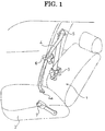
Fig. 1] Fig. 1 is a view schematically illustrating a seat belt apparatus including a buckle of an example according to an embodiment of the present invention. - [
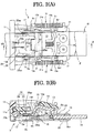
Fig. 2] Fig. 2(A) is a top view (plan view) partially illustrating the buckle of the seat belt apparatus of the example in a state in which the tongue is not inserted, andFig. 2(B) is a cross-sectional view taken along a line IIB-IIB inFig. 1(A) . - [
Fig. 3] Fig. 3(A) is a top view (plan view) partially illustrating the buckle of the example in a state in which the tongue is inserted, andFig. 3(B) is a cross-sectional view taken along a line IIIB-IIIB inFig. 3(A) . - [
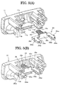
Fig. 4] Fig. 4(A) is a perspective view indicating a positional relationship of a tongue, an ejector, an ejector spring, and a base viewed obliquely from above, andFig. 4(B) is a perspective view indicating the relationship of the same viewed obliquely from below. - [
Fig. 5] Fig. 5(A) is an exploded perspective view illustrating an operation button and an impact absorbing mechanism of the example, andFig. 5(B) is a perspective view illustrating a sub assembly in which the impact absorbing mechanism is integrally mounted in the operation button. - [
Fig. 6] Fig. 6(A) is a front view illustrating an impact receiver of the impact absorbing mechanism,Fig. 6(B) is a top view (plan view) of the impact receiver, andFig. 6(C) is a left side view of the impact receiver inFig. 6(B) . - [
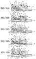
Fig. 7] Fig. 7(A) to Fig. 7(E) are views indicating operations of the buckle of the example. - [
Fig. 8] Fig. 8 is a perspective view illustrating a slider of a buckle of another example according to the embodiment of the present invention. - [
Fig. 9] Fig. 9 is a view for explaining how the slider in the example illustrated inFig. 8 is slowed down. - [
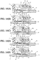
Fig. 10] Fig. 10(A) to Fig. 10(E) are views indicating operations of the buckle of the other example. Description of Embodiments - Hereinafter, an embodiment of the present invention is described with reference to the drawings.
- As illustrated in
Fig. 1 , aseat belt apparatus 1 of this example has basically the same configuration as widely known three-point seat belt apparatuses. In the drawings, areference numeral 1 denotes the seat belt apparatus, 2 denotes a vehicle seat, 3 denotes a seat belt retractor disposed adjacent to thevehicle seat vehicle sheet 2 at its end, 5 denotes aguide anchor 5 configured to guide theseat belt 4 withdrawn from the seat belt retractor 3 toward the shoulder of the occupant, 6 denotes a tongue slidably supported by theseat belt 4 guided by theguide anchor tongue 6 is inserted such that thebuckle 7 engages with thetongue 6 in a removable manner. - The configuration and the operation of the
buckle 7 of this example are substantially identical to those of the buckle described in Japanese Unexamined Patent Application Publication No.2012-126254 buckle 7 of this example, which include the configuration and the operation identical to those of the buckle described in Japanese Unexamined Patent Application Publication No.2012-126254 - As illustrated in
Figs. 2(A) and 2(B) ,Figs. 3(A) and 3(B) , andFigs. 4(A) and 4(B) , as in the buckle described in Japanese Unexamined Patent Application Publication No.2012-126254 buckle 7 of this example includes a damper (impact absorbing mechanism) 24, which is not included in the buckle described in Japanese Unexamined Patent Application Publication No.2012-126254 - The
buckle 7 of this example has thetongue inlet 17 at a position between an end of the bottom 8c of thebase 8 and theoperation button 11. In addition, the above-described components (indicated by thereference numerals 9 to 16) of thebuckle 7 are mounted on thebase 8. Then, the bottom 8c of thebase 8 is fixed to abracket 18 fixed to the chassis so that thebuckle 7 is fixed to the chassis through thebracket 18. In this case, thebracket 18 is sandwiched between anend 8c1 of the bottom 8c of thebase 8 opposite the end adjacent to thetongue inlet 17 and aplate 19 and fastened by a pair ofrivets 20, whereby thebuckle 7 is attached to thebracket 18. Although not illustrated, as in the buckle described in Japanese Unexamined Patent Application Publication No.2012-126254 base 8 to which the above-described components (9 to 16) of thebuckle 7 are mounted is covered by an upper cover and a lower cover from above and below. - In addition, in the
buckle 7 of this example, theejector spring 16 includes afirst ejector spring 16a and asecond ejector spring 16b. The first and second ejector springs 16a and 16b each have a smaller elastic constant, a smaller coil diameter, and a smaller wire diameter than conventional ejector springs. However, the first and second ejector springs 16a and 16b are identical to each other in the elastic constant and size (a coil diameter, a wire diameter, and a length in the longitudinal direction). - In addition, the entire
first ejector spring 16a is disposed at an outer side of thefirst side wall 8a of the base 8 (side opposite to thesecond side wall 8b) so as to be positioned outside an area α, which is a movement path of the engagingportion 6a of thetongue 6 in thebuckle 7, and outside an imaginary extended area β, which extends from the area α in the movement direction of the engagingportion 6a. In addition, the entire of thesecond ejector spring 16b is disposed at an outer side of thesecond side wall 8b of the base 8 (side opposite to thefirst side wall 8a) so as to be positioned outside the area α and the imaginary extended area β. - In this case, the first and second ejector springs 16a and 16b are each supported by an ejector
spring guide support 21 fixed to each of ends 8a1 and 8b1, which are fixed to thebracket 18, of the respective first andsecond side walls spring guide support 21 includes a firstejector spring guide 21a extending along or substantially parallel to thefirst side wall 8a toward thetongue inlet 17 and a secondejector spring guide 21b extending along or substantially parallel to thesecond side wall 8b toward thetongue inlet 17. Then, thefirst ejector spring 16a fitted to the firstejector spring guide 21a is supported and guided by the firstejector spring guide 21a, and thesecond ejector spring 16b fitted to the secondejector spring guide 21b is supported and guided by the secondejector spring guide 21b. - As illustrated in
Figs. 4(A) and 4(B) , the first andsecond side walls holes ejector 15. Afirst end portion 15a in a direction perpendicular or substantially perpendicular to the movement direction of theejector 15 is disposed through the first throughhole 22 in a slidable manner, and asecond end portion 15b of theejector 15 in the above-described direction disposed through the second throughhole 23 in a slidable manner. - In addition, the
first end portion 15a of theejector 15 is slidably fitted to the firstejector spring guide 21a, and thesecond end portion 15b of theejector 15 is slidably fitted to the secondejector spring guide 21b. Thefirst end portion 15a of theejector 15 is constantly biased toward thetongue inlet 17 by a biasing force of thefirst ejector spring 16a, and thesecond end portion 15b of theejector 15 is constantly biased toward thetongue inlet 17 by a biasing force of thesecond ejector spring 16b. - As illustrated in
Figs. 2(A) and 2(B) ,Figs. 3(A) and 3(B) , andFigs. 5(A) and 5(B) , thedamper 24 includes animpact receiver 25 and adamper spring 26 configured to bias theimpact receiver 25. As illustrated inFigs. 6(A) to 6(C) , theimpact receiver 25 includes abody 25a and aspring support 25b supporting thedamper spring 26. - The
body 25a includes a pair ofimpact receiving arms front end 13a of the slider 13 (illustrated inFig. 2(B) andFig. 3(B) ) is able to come in contact withfront ends impact receiving arms slider 13. Theimpact receiving arms stopper - The
spring support 25b is a cylindrical bar. Thespring support 25b is positioned at a middle between thearms body 25a as illustrated inFig. 6(A) and extends integrally from thebody 25a through thesupport member 25c in the movement direction of theimpact receiver 25. Thebody 25a, thespring support 25b, and thesupport member 25c (i.e., the impact receiver 25) are integrally formed of a single resin member. - As illustrated in
Figs. 2(A) and 2(B) ,Figs. 3(A) and 3(B) , andFigs. 5(A) and 5(B) , theoperation button 11 includes a pair ofguides recess 11c. Theguides operation button 11. Vertical walls of theguides holes 11d and 11e each having a partially open upper side. Therecess 11c has a cylindrical shape having a diameter large enough to receive thespring support 25b and thedamper spring 26. - The
body 25a of theimpact receiver 25 is slidably supported by the pair ofguides operation button 11 with thedamper spring 26 being fitted to thespring support 25b. In such a case, when a first end portion of thespring support 25b enters therecess 11c, a first end of thedamper spring 26 enters therecess 11c and comes in contact with the bottom of therecess 11c. In addition, thestoppers holes 11d and 11e. In this way, thedamper 24 is integrally mounted to theoperation button 11, and thus an operation button sub assembly is obtained. As a result, thedamper 24 is able to be mounted easily. In the operation button sub assembly in which thedamper 24 is mounted, thedamper spring 26 is compressed between theoperation button 11 and theimpact receiver 25. Thus, theimpact receiver 25 is constantly biased toward thelatch 9 by thedamper spring 26, and theimpact receiver 25 is held in a non-operating position at which thestoppers holes 11d and 11e, as illustrated inFig. 5(B) (Fig. 5(B) shows only a state in which thestopper 25a5 is in contact with the edge 11d1 of the through hole 11d, but the same is applicable to theother stopper 25a6). In other words, thedamper 24 is in a non-operating state. - When the
damper 24 is in the non-operating state, the front ends 25a3 and 25a4 of the respectiveimpact receiving arms body 25a are positioned closer to thelatch 9 than the front ends of theguides operation button 11 in the non-operating position. In this case, the front ends of theguides latch 9 than thestop 11f (corresponding to the stop of the present invention) of theoperation button 11. Thestop 11f of theoperation button 11 in the non-operating state causes theslider 13 that has come into contact therewith finally to stop. - With this configuration, when the
slider 13 is moved by the biasing force of theslider spring 14, thefront end 13a of theslider 13 comes in contact with the front ends 25a3 and 25a4 of the respectiveimpact receiving arms guides damper spring 26 is smaller than the biasing force of theslider spring 14. Thus, after theslider 13 is moved by the biasing force of theslider spring 14 such that thefront end 13a thereof comes in contact with the front ends 25a3 and 25a4 of the respectiveimpact receiving arms slider 13 is able to move further together with thebody 25a while compressing thedamper spring 26. Then, theslider 13 stops when thefront end 13a thereof comes in contact with thestop 11f of theoperation button 11. Thus, theslider 13 is not in contact with theguides stop 11f of theoperation button 11, theslider 13 may be configured to come in contact with theguides body 25 needs to be in contact with a portion of theoperation button 11 to stop the movement thereof. - The
operation button 11 is normally (during non-operating state) held in the non-operating position illustrated inFigs. 2(A) and 2(B) andFigs. 3(A) and 3(B) by the biasing force of thebutton spring 12. Thus, as in the conventionally known buckles, theoperation button 11 is held in the non-operating position by a stopper (not illustrated) disposed on a cover of the buckle or thebase 8 so as not to be moved further in a biasing direction of the button spring 12 (to the left inFig. 2(B) andFig. 3(B) , i.e., a direction opposite to the unlatching direction). - Next, operations of the
buckle 7 of this example having the above-described configuration are described. - When the
tongue 6 is removed from thebuckle 7, thebuckle 7 is in the non-operating state as illustrated inFigs. 2(A) and 2(B) andFig. 7(A) . In the non-operating state of thebuckle 7, thelatch 9 is in the non-latching (non-engaging) position (non-operating position), and theoperation button 11 and theslider 13 are in the non-operating positions. In addition, thedamper 24 is in the non-operating state as illustrated inFigs. 2(A) and 2(B) andFig. 7(A) . Thus, the front end of theslider 13 is in contact with the lockingpin 10 and is not in contact with theimpact receiver 25 of thedamper 24. In addition, theslider 13 is in the non-locking position (non-operating position) at which theslider 13 does not lock thelatch 9. - In addition, the
ejector 15 is positioned in the non-operating position at which theejector 15 is positioned closest to thetongue inlet 17. In theejector 15 positioned in the non-operating position, the first andsecond end portions ejector 15 stop at predetermined positions while being fitted with the first and second ejector spring guides 21a and 21b. In this state, the first and second ejector springs 16a and 16b bias the respective first andsecond end portions ejector 15 with relatively small force toward thetongue inlet 17. In addition, the slopingfront end 13a of theslider 13 is in contact with the lockingpin 10 by the biasing force of theslider spring 14, and theslider 13 is held in the non-operating position. - When the
buckle 7 is in such a non-operating state, the engagingportion 6a of thetongue 6 is inserted to thebuckle 7 through thetongue inlet 17 such that theseat belt 4 is fastened. When the engagingportion 6a is inserted into thebuckle 7 by a predetermined length, the front end of the engagingportion 6a is in contact with an end of theejector 15. When thetongue 6 is inserted further into thebuckle 7, theejector 15 is pushed by the engagingportion 6a and moved to the right inFigs. 2(A) and 2(B) andFig. 7(A) while compressing the first and second ejector springs 16a and 16b. When thetongue 6 is inserted further into thebuckle 7, the front end of the engagingportion 6a comes in contact and pushes a first pressedportion 9a of thelatch 9. Then, thelatch 9 turns in a counterclockwise direction inFig. 2(B) andFig. 7(A) aboutpivot portions latch 9 and rotatably supported by theside walls portion 9d of thelatch 9 moves toward the movement path of the engagingportion 6a of thetongue 6 At this time, theslider 13 turns together with thelatch 9 in the same direction. - As illustrated in
Fig. 7(B) , when anengaging hole 6b of the engagingportion 6a of thetongue 6 reaches the position where the latchingportion 9d of thelatch 9 is able to enter theengaging hole 6b, the latchingportion 9d enters the engaginghole 6b of the engagingportion 6a. As illustrated inFig. 7(C) , theslider 13 moves away from the lockingpin 10 due to the turn of theslider 13 and moves to a position under the lockingpin 10. Then, immediately before thefront end 13a of theslider 13 comes in contact with thestop 11f of theoperation button 11, theslider 13 comes in contact with the front ends 25a3 and 25a4 of the respectiveimpact receiving arms slider 13 moves further together with theimpact receiver 25 while compressing thedamper spring 26 of thedamper 24. In such a case, resistance is applied to theslider 13 by the compression of thedamper spring 26, and thus the movement of theslider 13 is slowed down. - As illustrated in
Fig. 7(D) , when thefront end 13a of theslider 13 comes in contact with thestop 11f of theoperation button 11, theslider 13 stops and is in the locking position. At this time, the impact of the contact between theslider 13 and thestop 11f is reduced since the movement of theslider 13 is slowed down by thedamper 24 before theslider 13 comes in contact with thestop 11f. This reduces the noise generated when theslider 13 comes in contact with thestop 11f. Then, theslider 13 is positioned between thelatch 9 at the latching position and the lockingpin 10 and held down by the lockingpin 10, and thus thelatch 9 is held in the latching position by theslider 13. - When the occupant releases the
tongue 6 in this state, the engagingportion 6a is pushed and moved by theejector 15 in a removal direction in which thetongue 6 is removed from thebuckle 7. As a result, as illustrated inFigs. 3(A) and 3(B) andFig. 7(E) , the edge of theengaging hole 6b of the engagingportion 6a comes in contact with the latchingportion 9d of thelatch 9, and the lackingportion 6a is prevented from moving in the removal direction in which thetongue 6 is removed from thebuckle 7. In this way, thetongue 6 engages with thebuckle 7. Then, an extra withdrawn portion of theseat belt 4 is retracted by the seat belt retractor 3, and thus theseat belt 4 is fastened to the occupant. - When the
operation button 11 of thebuckle 7 in an operational state illustrated inFigs. 3(A) and Fig. 3(B) andFig. 7 (E) is pushed and moved to the right inFigs. 3(A) and 3(B) to release theseat belt 4, theoperation button 11 comes in contact with theslider 13 and pushes theslider 13. Then, theslider 13 moves to the right inFigs. 3(A) and 3(B) while compressing theslider spring 14. When theslider 13 moves away from the position under the lockingpin 10, thelatch 9 turns in the counterclockwise direction inFig. 3(B) about thepivot portions slider 13. As a result, the latchingportion 9d of thelatch 9 moves in a direction away from the movement path of the engagingportion 6a of thetongue 6. - When the latching
portion 9d of thelatch 9 is removed from the engaginghole 6b, thelatch 9 is unlatched from thetongue 6. Then, theejector 15 is moved together with thetongue 6 toward the tongue inlet 17 (to the left inFigs. 3(A) and 3(B) ) by the biasing force of the first and second ejector springs 16a and 16b. Thus, thetongue 6 is removed from thebuckle 7. Then, theseat belt 4 withdrawn so as to be worn is retracted by the seat belt retractor 3. - As illustrated in
Fig. 2(B) , when thelatch 9 comes in contact with the lockingpin 10, thelatch 9 stops turning and is positioned in the non-operating position (non-latching position) as illustrated inFig. 2(B) . In addition, theimpact receiver 25 moves toward the non-operating position thereof by the biasing force of thedamper spring 26 due to the movement of theslider 13. Then, when thestoppers impact receiver 25 comes in contact with theedges 11d1 and 11e1 of the throughholes 11d and 11e of theoperation button 11, theimpact receiver 25 stops and is positioned in the non-operating position. In addition, due to the movement of theslider 13, thefront end 13a of theslider 13 moves away from the front ends 25a3 and 25a4 of the respectiveimpact receiving arms Fig. 2(B) andFig. 7(A) , theslider 13 is held in the non-operating state in which thefront end 13a of theslider 13 is in contact with the lockingpin 10 by the biasing force of theslider spring 14. - The other configurations and operations of the
buckle 7 in this example are substantially the same as those of the buckle described in Japanese Unexamined Patent Application Publication No.2012-126254 - In the
buckle 7 of this example having the above-described configuration, during the engagement operation of thelatch 9 with thetongue 6, thedamper 24 slows down the movement of theslider 13 before theslider 13 comes in contact with thestop 11f of theoperation button 11. Then, theslider 13 comes in contact with thestop 11f of theoperation button 11. Thus, the impact of the contact between theslider 13 and thestop 11f is reduced. This effectively reduces the noise generated when theslider 13 comes in contact with thestop 11f. Particularly, since theslider 13 is slowed down immediately before theslider 13 comes in contact with thestop 11f of theoperation button 11, theslider 13 is not slowed down too much. Thus, although thebuckle 7 includes thedamper 24, thetongue 6 is able to promptly engage with thebuckle 7, and the noise is able to be effectively reduced. - In addition, the
damper 24 includes theimpact receiver 25 and thedamper spring 26, and theslider 13 comes in contact with theimpact receiver 25 and elastically deforms thedamper spring 26 before theslider 13 comes in contact with thestop 11f of theoperation button 11, whereby the movement of theslider 13 is slowed down. Thus, the above-described reduction in the impact is achieved by thedamper 24 having such a simple configuration. - In the
seat belt apparatus 1 including thebuckle 7 of this example, the noise generated during the engagement operation of thetongue 6 with thebuckle 7 is reduced. Thus, comfortability of the occupant during the engagement operation of thetongue 6 with thebuckle 7 is improved. - The other operational advantages of the
buckle 7 and theseat belt apparatus 1 of this example are substantially the same as those of the buckle described in Japanese Unexamined Patent Application Publication No.2012-126254 -
Fig. 8 is a perspective view illustrating a slider of another example of the embodiment of the buckle according to the present invention.Fig. 9 is a view for explaining how the movement of the slider in this example is slowed down. Components identical to those in the previously described example are assigned the same reference numerals as those in the previously described example and are not described in detail. - In the
buckle 7 of the previously described example, thedamper 24 is provided in theoperation button 11, and thedamper 24 includes theimpact receiver 25 and thedamper spring 26. However, as illustrated inFig. 8 , in thebuckle 7 of this example, thedamper 24 is provided on the upper surface of theslider 13. - In other words, the
damper 24 of this example includes a pair ofimpact receivers impact receiver slider spring 14 that biases theslider 13. Theimpact receivers slider 13, and theimpact receivers slider 13 are formed of a single resin member. Each of theimpact receivers slider 13. - As illustrated in
Fig. 9 , the pair ofimpact receivers pin 10 during the operation of theslider 13. In such a case, theimpact receivers pin 10 immediately before thefront end 13a of theslider 13 comes in contact with thestop 11f of theoperation button 11. Then, after theimpact receivers pin 10 during the operation of theslider 13, further movement of theslider 13 causes theimpact receivers pin 10. As in the previously described example, theslider 13 is slowed down immediately before thefront end 13a of theslider 13 comes in contact with thestop 11f of theoperation button 11, due to the elastic force generated by the elastic deformation of the impact receives 27 and 28. Then, thefront end 13a of theslider 13 comes in contact with thestop 11f. As a result, theslider 13 stops and is positioned in the locking position. As in the previously described buckle, since theslider 13 that has been slowed down comes in contact with thestop 11f, the noise generated when theslider 13 comes in contact with thestop 11f is reduced. The other configurations of thebuckle 7 in this example are substantially the same as those of thebuckle 7 in the previously described example and the buckle described in Japanese Unexamined Patent Application Publication No.2012-126254 - Next, operations of the
buckle 7 of this example having the above-described configuration are described. - The
buckle 7 of this example operates in the same way as thebuckle 7 of the previously described example from the insertion of thetongue 6 into thebuckle 7 in the non-operating state to the movement of thelatch 9 to the latching position. However, as illustrated inFigs. 10(A) and 10(B) , theimpact receivers pin 10 when thefront end 13a of theslider 13 of thebuckle 7 is in contact with the lockingpin 10. - Then, in the
buckle 7 of this example, when thefront end 13a of theslider 13 of thebuckle 7 moves away from the lockingpin 10 to allow theslider 13a to move relative to thelatch 9, theimpact receivers pin 10 immediately before the front end of theslider 13a comes in contact with thestop 11f of theoperation button 11 as illustrated inFig. 10(C) . Then, the further movement of theslider 13 causes theimpact receivers pin 10. The resistance is applied to theslider 13 due to the elastic force generated by the elastic deformation of theimpact receivers slider 13 is slowed down. - As illustrated in
Fig. 10 (D) , when thefront end 13a of theslider 13 comes in contact with thestop 11f of theoperation button 11, as in thebuckle 7 of the previously described example, theslider 13 stops and is positioned in the locking position. At this time, since the movement of theslider 13 is slowed down by thedamper 24 before theslider 13 comes in contact with thestop 11f, the impact of the contact between theslider 13 and thestop 11f is reduced. This reduces the noise generated when theslider 13 comes in contact with thestop 11f. Then, theslider 13 positioned between thelatch 9, which is positioned in the latching position, and the lockingpin 10 is held down by the lockingpin 10. Thus, thelatch 9 is held in the latching position by theslider 13. - In such a state, if the occupant releases the
tongue 6, the engagingportion 6a is pushed and moved by theejector 15 in the removal direction in which thetongue 6 is removed from thebuckle 7. As a result, as illustrated inFig. 10(E) , the edge of theengaging hole 6b of the engagingportion 6a comes in contact with the latchingportion 9d of thelatch 9, and thus the engagingportion 6a is prevented from moving in the removal direction in which thetongue 6 is removed from thebuckle 7. Thetongue 6 engages with thebuckle 7 in this way. Then, an extra withdrawn portion of theseat belt 4 is retracted by the seat belt retractor 3, and thus theseat belt 4 is fastened to the occupant. - When the
operation button 11 of thebuckle 7 in the operating state illustrated inFig. 10(E) is pushed and moved to the right inFig. 10(E) to release theseat belt 4, thetongue 6 is disengaged from thelatch 9, and thetongue 6 is removed from thebuckle 7 as in thebuckle 7 of the previously described example. Then, theseat belt 4 withdrawn so as to be worn is retracted by the seat belt retractor 3. In addition, as illustrated inFig. 10(A) , when thelatch 9 comes in contact with the lockingpin 10, thelatch 9 stops turning, and thelatch 9 is positioned in the non-operating position (non-latching position) as illustrated inFig. 10(A) . In addition, due to the movement of theslider 13, theimpact receivers impact receivers pin 10 return to the non-operating state. - The other operations of the
buckle 7 in this example are substantially the same as those of thebuckle 7 of the previously described example and the buckle described in Japanese Unexamined Patent Application Publication No.2012-126254 - In the
buckle 7 of this example having the above-described configuration, theimpact receivers slider 13 are integrally formed of a single component. Thus, the number of components is reduced, and the configuration of thedamper 24 is simplified. - Other operational advantages of the
buckle 7 in this example are substantially the same as those in thebuckle 7 in the previously described example. - In the above-described examples, the
slider 13 is held in the locking position by thestop 11f of theoperation button 11, but may be heled in the locking position by a stopper included in any other unmovable component of thebuckle 7 such as thebase 8 or the cover. In addition, the buckle according to the present invention is applicable to conventionally known buckles, such as the buckle described inPatent Literature 1, in which the ejector spring is disposed in the area α, which is the movement path of the engagingportion 6a of thetongue 6, and the imaginary extended area P, which extends from the area α in the movement direction of the engagingportion 6a. Various modifications may be applied to the present invention without departing from the scope of the claims. - The buckle and the seat belt apparatus of the present invention are advantageously applicable to a buckle, with which a tongue supported by a seat belt engages so as to enable the seat belt to be worn, and a seat belt apparatus including such a buckle.
-
- 1
- seat belt apparatus
- 3
- seat belt retractor
- 4
- seat belt
- 6
- tongue
- 7
- buckle
- 8
- base
- 8a, 8b
- side wall
- 8c
- bottom
- 9
- latch
- 11
- operation button
- 11a, 11b
- guide
- 11c
- recess
- 11d, 11e
- through hole
- 11d1
- edge
- 11f
- stop
- 12
- button spring
- 13
- slider
- 13a
- front end
- 14
- slider spring
- 15
- ejector
- 17
- tongue inlet
- 24
- damper
- 25
- impact receiver
- 25a
- body
- 25a1, 25a2
- impact receiving arm
- 25a3, 25a4
- front end
- 25a5, 25a6
- stoppers
- 25b
- spring support
- 26
- damper spring
- 27, 28
- impact receiver
Claims (6)
- A buckle at least comprising:a base;a tongue inlet through which an engaging portion of a tongue is inserted;a latch supported by the base so as to move between a non-engaging position at which the latch does not engage with the engaging portion of the tongue inserted through the tongue inlet and an engaging position at which the latch engages with the engaging portion of the tongue inserted through the tongue inlet;a latch retainer configured to be held in a non-locking position at which the latch retainer does not lock the latch positioned in the non-engaging position and configured to move from the non-locking position during operation of the latch and come in contact with a stop so as to be held in a locking position at which the latch retainer locks the latch positioned in the engaging position; andan unlocking operation member configured to move the latch positioned in the engaging position to the non-engaging position, whereinan impact absorbing mechanism configured to, during the operation of the latch, slow down the movement of the latch retainer before the latch retainer in motion comes in contact with the stop, such that the latch retainer that is slowed down comes in contact with the stop.
- The buckle according to Claim 1, wherein the impact absorbing mechanism includes: an impact receiver with which the latch retainer comes in contact before coming into contact with the stop; and a damper spring configured to bias the impact receiver, and
the latch retainer comes in contact with the impact receiver so as to elastically deform the damper spring, such that the movement of the latch retainer is slowed down. - The buckle according to Claim 2, wherein the impact receiver and the damper spring are integrally provided in the unlocking operation member.
- The buckle according to Claim 1, wherein the impact absorbing mechanism includes an impact receiver that is elastically deformable, and
the impact receiver is elastically deformed before the latch retainer in motion comes in contact with the stop, such that the movement of the latch retainer is slowed down. - The buckle according to Claim 4, wherein the impact receiver has a fin-like shape and is integrally formed with the latch retainer.
- A seat belt apparatus at least comprising:a seat belt configured to hold an occupant;a seat belt retractor disposed on a chassis and configured to retract the seat belt; anda buckle disposed on the chassis and configured to engage with a tongue in a removable manner, whereinthe buckle is any one of the buckles according to Claims 1 to 5.
Applications Claiming Priority (2)
| Application Number | Priority Date | Filing Date | Title |
|---|---|---|---|
| JP2013161451A JP6176715B2 (en) | 2013-08-02 | 2013-08-02 | Buckle and seat belt device provided with the same |
| PCT/JP2014/067764 WO2015015997A1 (en) | 2013-08-02 | 2014-07-03 | Buckle and seatbelt device with same |
Publications (3)
| Publication Number | Publication Date |
|---|---|
| EP3028593A1 true EP3028593A1 (en) | 2016-06-08 |
| EP3028593A4 EP3028593A4 (en) | 2017-02-01 |
| EP3028593B1 EP3028593B1 (en) | 2017-11-15 |
Family
ID=52431537
Family Applications (1)
| Application Number | Title | Priority Date | Filing Date |
|---|---|---|---|
| EP14831159.0A Active EP3028593B1 (en) | 2013-08-02 | 2014-07-03 | Buckle and seatbelt device with same |
Country Status (5)
| Country | Link |
|---|---|
| US (1) | US9743718B2 (en) |
| EP (1) | EP3028593B1 (en) |
| JP (1) | JP6176715B2 (en) |
| CN (1) | CN105324051B (en) |
| WO (1) | WO2015015997A1 (en) |
Families Citing this family (4)
| Publication number | Priority date | Publication date | Assignee | Title |
|---|---|---|---|---|
| US9974365B2 (en) * | 2014-11-07 | 2018-05-22 | Ford Global Technologies, Llc | Buckle guide |
| US9949535B2 (en) * | 2016-03-28 | 2018-04-24 | GM Global Technology Operations LLC | Seat belt buckle extender |
| WO2018069311A1 (en) | 2016-10-11 | 2018-04-19 | Telefonaktiebolaget Lm Ericsson (Publ) | Methods and apparatus for adapting srs switching accounting for measurement procedure |
| CN108372840B (en) * | 2018-04-18 | 2024-05-31 | 重庆光大产业有限公司 | Lock catch device assembly |
Family Cites Families (11)
| Publication number | Priority date | Publication date | Assignee | Title |
|---|---|---|---|---|
| JP3650271B2 (en) * | 1998-07-27 | 2005-05-18 | 株式会社東海理化電機製作所 | buckle |
| JP3983941B2 (en) * | 1999-07-13 | 2007-09-26 | 芦森工業株式会社 | Buckle device |
| JP4101982B2 (en) * | 1999-08-13 | 2008-06-18 | 芦森工業株式会社 | Buckle device |
| EP1219197B1 (en) * | 1999-08-13 | 2015-09-30 | Ashimori Industry Co., Ltd. | Buckle device |
| JP3963866B2 (en) * | 2003-06-10 | 2007-08-22 | 芦森工業株式会社 | Buckle device |
| JP5195662B2 (en) * | 2009-06-16 | 2013-05-08 | トヨタ紡織株式会社 | Buckle structure of vehicle seat |
| JP5808093B2 (en) * | 2010-09-28 | 2015-11-10 | タカタ株式会社 | Tongue and seat belt device using the same |
| JP5653741B2 (en) * | 2010-12-15 | 2015-01-14 | タカタ株式会社 | Buckle and seat belt device provided with the same |
| JP5762985B2 (en) * | 2012-01-11 | 2015-08-12 | 株式会社東海理化電機製作所 | Buckle device |
| DE102013212927B3 (en) * | 2013-07-03 | 2014-08-21 | Autoliv Development Ab | Buckle for safety belt system for locking belt tongue used in motor vehicle, has damping element that is arranged on inner side of housing to expected impact surface of latch mechanism components during processing or unlocking movement |
| DE102013020618B4 (en) * | 2013-12-02 | 2022-12-29 | Zf Automotive Germany Gmbh | belt buckle |
-
2013
- 2013-08-02 JP JP2013161451A patent/JP6176715B2/en active Active
-
2014
- 2014-07-03 US US14/904,939 patent/US9743718B2/en active Active
- 2014-07-03 EP EP14831159.0A patent/EP3028593B1/en active Active
- 2014-07-03 WO PCT/JP2014/067764 patent/WO2015015997A1/en active Application Filing
- 2014-07-03 CN CN201480034144.7A patent/CN105324051B/en active Active
Non-Patent Citations (1)
| Title |
|---|
| See references of WO2015015997A1 * |
Also Published As
| Publication number | Publication date |
|---|---|
| WO2015015997A1 (en) | 2015-02-05 |
| US20160135548A1 (en) | 2016-05-19 |
| EP3028593B1 (en) | 2017-11-15 |
| CN105324051B (en) | 2018-05-22 |
| EP3028593A4 (en) | 2017-02-01 |
| JP2015029697A (en) | 2015-02-16 |
| JP6176715B2 (en) | 2017-08-09 |
| US9743718B2 (en) | 2017-08-29 |
| CN105324051A (en) | 2016-02-10 |
Similar Documents
| Publication | Publication Date | Title |
|---|---|---|
| US8079616B2 (en) | Seatbelt apparatus | |
| EP3028593B1 (en) | Buckle and seatbelt device with same | |
| KR20140007905A (en) | Height adjuster for a fastening fitting of a safety belt system | |
| JPH04113959A (en) | Shoulder adjuster | |
| EP1721776A2 (en) | Slide adjuster for an automobile seat | |
| JPWO2008084609A1 (en) | Shoulder adjuster | |
| KR100850045B1 (en) | Non-inertial release safety restraint belt buckle | |
| CN107105827B (en) | Seat belt buckle device and system | |
| JP5653741B2 (en) | Buckle and seat belt device provided with the same | |
| JP6235328B2 (en) | Slide rail device for vehicle seat | |
| US10455903B2 (en) | Buckle device | |
| JP5430331B2 (en) | Lock unit mounting structure for vehicle seat slide lock device | |
| US6370742B1 (en) | Buckle with movement prevention device | |
| JP6487757B2 (en) | Shoulder adjuster for seat belt | |
| US6385823B1 (en) | Buckle with noise prevention mechanism | |
| JP6208778B2 (en) | Height adjuster device, seat belt device including height adjuster device, and method for manufacturing height adjuster device | |
| US6427297B1 (en) | Buckle with smooth tongue insertion mechanism | |
| JP7200029B2 (en) | Operation mechanism of seat belt shoulder anchor device | |
| CN209757043U (en) | Height adjusting device for safety belt | |
| JP3207871U (en) | Super easy belt loop for child seat | |
| JP6438864B2 (en) | Shoulder adjuster device and seat belt device | |
| WO2020146262A1 (en) | Cinch locking tongue for a vehicle occupant restraint system | |
| JP3957129B2 (en) | Crew restraint system | |
| JPH0467842B2 (en) | ||
| JPH04120607U (en) | Buckle for seat belt |
Legal Events
| Date | Code | Title | Description |
|---|---|---|---|
| PUAI | Public reference made under article 153(3) epc to a published international application that has entered the european phase |
Free format text: ORIGINAL CODE: 0009012 |
|
| 17P | Request for examination filed |
Effective date: 20151211 |
|
| AK | Designated contracting states |
Kind code of ref document: A1 Designated state(s): AL AT BE BG CH CY CZ DE DK EE ES FI FR GB GR HR HU IE IS IT LI LT LU LV MC MK MT NL NO PL PT RO RS SE SI SK SM TR |
|
| AX | Request for extension of the european patent |
Extension state: BA ME |
|
| DAX | Request for extension of the european patent (deleted) | ||
| A4 | Supplementary search report drawn up and despatched |
Effective date: 20170105 |
|
| RIC1 | Information provided on ipc code assigned before grant |
Ipc: B60R 22/18 20060101ALI20161223BHEP Ipc: B60R 22/12 20060101ALI20161223BHEP Ipc: A44B 11/25 20060101AFI20161223BHEP |
|
| GRAP | Despatch of communication of intention to grant a patent |
Free format text: ORIGINAL CODE: EPIDOSNIGR1 |
|
| INTG | Intention to grant announced |
Effective date: 20170614 |
|
| GRAS | Grant fee paid |
Free format text: ORIGINAL CODE: EPIDOSNIGR3 |
|
| GRAA | (expected) grant |
Free format text: ORIGINAL CODE: 0009210 |
|
| AK | Designated contracting states |
Kind code of ref document: B1 Designated state(s): AL AT BE BG CH CY CZ DE DK EE ES FI FR GB GR HR HU IE IS IT LI LT LU LV MC MK MT NL NO PL PT RO RS SE SI SK SM TR |
|
| REG | Reference to a national code |
Ref country code: CH Ref legal event code: EP Ref country code: GB Ref legal event code: FG4D Ref country code: AT Ref legal event code: REF Ref document number: 945412 Country of ref document: AT Kind code of ref document: T Effective date: 20171115 |
|
| REG | Reference to a national code |
Ref country code: IE Ref legal event code: FG4D |
|
| REG | Reference to a national code |
Ref country code: DE Ref legal event code: R096 Ref document number: 602014017408 Country of ref document: DE |
|
| REG | Reference to a national code |
Ref country code: NL Ref legal event code: MP Effective date: 20171115 |
|
| REG | Reference to a national code |
Ref country code: LT Ref legal event code: MG4D |
|
| REG | Reference to a national code |
Ref country code: AT Ref legal event code: MK05 Ref document number: 945412 Country of ref document: AT Kind code of ref document: T Effective date: 20171115 |
|
| REG | Reference to a national code |
Ref country code: DE Ref legal event code: R081 Ref document number: 602014017408 Country of ref document: DE Owner name: JOYSON SAFETY SYSTEMS JAPAN G.K., JP Free format text: FORMER OWNER: TAKATA CORPORATION, TOKYO, JP Ref country code: DE Ref legal event code: R082 Ref document number: 602014017408 Country of ref document: DE Representative=s name: VOSSIUS & PARTNER PATENTANWAELTE RECHTSANWAELT, DE Ref country code: DE Ref legal event code: R081 Ref document number: 602014017408 Country of ref document: DE Owner name: JOYSON SAFETY SYSTEMS JAPAN K.K., JP Free format text: FORMER OWNER: TAKATA CORPORATION, TOKYO, JP |
|
| PG25 | Lapsed in a contracting state [announced via postgrant information from national office to epo] |
Ref country code: SE Free format text: LAPSE BECAUSE OF FAILURE TO SUBMIT A TRANSLATION OF THE DESCRIPTION OR TO PAY THE FEE WITHIN THE PRESCRIBED TIME-LIMIT Effective date: 20171115 Ref country code: NL Free format text: LAPSE BECAUSE OF FAILURE TO SUBMIT A TRANSLATION OF THE DESCRIPTION OR TO PAY THE FEE WITHIN THE PRESCRIBED TIME-LIMIT Effective date: 20171115 Ref country code: NO Free format text: LAPSE BECAUSE OF FAILURE TO SUBMIT A TRANSLATION OF THE DESCRIPTION OR TO PAY THE FEE WITHIN THE PRESCRIBED TIME-LIMIT Effective date: 20180215 Ref country code: FI Free format text: LAPSE BECAUSE OF FAILURE TO SUBMIT A TRANSLATION OF THE DESCRIPTION OR TO PAY THE FEE WITHIN THE PRESCRIBED TIME-LIMIT Effective date: 20171115 Ref country code: LT Free format text: LAPSE BECAUSE OF FAILURE TO SUBMIT A TRANSLATION OF THE DESCRIPTION OR TO PAY THE FEE WITHIN THE PRESCRIBED TIME-LIMIT Effective date: 20171115 Ref country code: ES Free format text: LAPSE BECAUSE OF FAILURE TO SUBMIT A TRANSLATION OF THE DESCRIPTION OR TO PAY THE FEE WITHIN THE PRESCRIBED TIME-LIMIT Effective date: 20171115 |
|
| PG25 | Lapsed in a contracting state [announced via postgrant information from national office to epo] |
Ref country code: BG Free format text: LAPSE BECAUSE OF FAILURE TO SUBMIT A TRANSLATION OF THE DESCRIPTION OR TO PAY THE FEE WITHIN THE PRESCRIBED TIME-LIMIT Effective date: 20180215 Ref country code: AT Free format text: LAPSE BECAUSE OF FAILURE TO SUBMIT A TRANSLATION OF THE DESCRIPTION OR TO PAY THE FEE WITHIN THE PRESCRIBED TIME-LIMIT Effective date: 20171115 Ref country code: GR Free format text: LAPSE BECAUSE OF FAILURE TO SUBMIT A TRANSLATION OF THE DESCRIPTION OR TO PAY THE FEE WITHIN THE PRESCRIBED TIME-LIMIT Effective date: 20180216 Ref country code: LV Free format text: LAPSE BECAUSE OF FAILURE TO SUBMIT A TRANSLATION OF THE DESCRIPTION OR TO PAY THE FEE WITHIN THE PRESCRIBED TIME-LIMIT Effective date: 20171115 Ref country code: RS Free format text: LAPSE BECAUSE OF FAILURE TO SUBMIT A TRANSLATION OF THE DESCRIPTION OR TO PAY THE FEE WITHIN THE PRESCRIBED TIME-LIMIT Effective date: 20171115 Ref country code: HR Free format text: LAPSE BECAUSE OF FAILURE TO SUBMIT A TRANSLATION OF THE DESCRIPTION OR TO PAY THE FEE WITHIN THE PRESCRIBED TIME-LIMIT Effective date: 20171115 |
|
| PG25 | Lapsed in a contracting state [announced via postgrant information from national office to epo] |
Ref country code: CZ Free format text: LAPSE BECAUSE OF FAILURE TO SUBMIT A TRANSLATION OF THE DESCRIPTION OR TO PAY THE FEE WITHIN THE PRESCRIBED TIME-LIMIT Effective date: 20171115 Ref country code: SK Free format text: LAPSE BECAUSE OF FAILURE TO SUBMIT A TRANSLATION OF THE DESCRIPTION OR TO PAY THE FEE WITHIN THE PRESCRIBED TIME-LIMIT Effective date: 20171115 Ref country code: EE Free format text: LAPSE BECAUSE OF FAILURE TO SUBMIT A TRANSLATION OF THE DESCRIPTION OR TO PAY THE FEE WITHIN THE PRESCRIBED TIME-LIMIT Effective date: 20171115 Ref country code: CY Free format text: LAPSE BECAUSE OF FAILURE TO SUBMIT A TRANSLATION OF THE DESCRIPTION OR TO PAY THE FEE WITHIN THE PRESCRIBED TIME-LIMIT Effective date: 20171115 Ref country code: DK Free format text: LAPSE BECAUSE OF FAILURE TO SUBMIT A TRANSLATION OF THE DESCRIPTION OR TO PAY THE FEE WITHIN THE PRESCRIBED TIME-LIMIT Effective date: 20171115 |
|
| REG | Reference to a national code |
Ref country code: DE Ref legal event code: R097 Ref document number: 602014017408 Country of ref document: DE |
|
| PG25 | Lapsed in a contracting state [announced via postgrant information from national office to epo] |
Ref country code: RO Free format text: LAPSE BECAUSE OF FAILURE TO SUBMIT A TRANSLATION OF THE DESCRIPTION OR TO PAY THE FEE WITHIN THE PRESCRIBED TIME-LIMIT Effective date: 20171115 Ref country code: IT Free format text: LAPSE BECAUSE OF FAILURE TO SUBMIT A TRANSLATION OF THE DESCRIPTION OR TO PAY THE FEE WITHIN THE PRESCRIBED TIME-LIMIT Effective date: 20171115 Ref country code: SM Free format text: LAPSE BECAUSE OF FAILURE TO SUBMIT A TRANSLATION OF THE DESCRIPTION OR TO PAY THE FEE WITHIN THE PRESCRIBED TIME-LIMIT Effective date: 20171115 Ref country code: PL Free format text: LAPSE BECAUSE OF FAILURE TO SUBMIT A TRANSLATION OF THE DESCRIPTION OR TO PAY THE FEE WITHIN THE PRESCRIBED TIME-LIMIT Effective date: 20171115 |
|
| PLBE | No opposition filed within time limit |
Free format text: ORIGINAL CODE: 0009261 |
|
| STAA | Information on the status of an ep patent application or granted ep patent |
Free format text: STATUS: NO OPPOSITION FILED WITHIN TIME LIMIT |
|
| 26N | No opposition filed |
Effective date: 20180817 |
|
| PG25 | Lapsed in a contracting state [announced via postgrant information from national office to epo] |
Ref country code: SI Free format text: LAPSE BECAUSE OF FAILURE TO SUBMIT A TRANSLATION OF THE DESCRIPTION OR TO PAY THE FEE WITHIN THE PRESCRIBED TIME-LIMIT Effective date: 20171115 |
|
| REG | Reference to a national code |
Ref country code: CH Ref legal event code: PL |
|
| GBPC | Gb: european patent ceased through non-payment of renewal fee |
Effective date: 20180703 |
|
| PG25 | Lapsed in a contracting state [announced via postgrant information from national office to epo] |
Ref country code: MC Free format text: LAPSE BECAUSE OF FAILURE TO SUBMIT A TRANSLATION OF THE DESCRIPTION OR TO PAY THE FEE WITHIN THE PRESCRIBED TIME-LIMIT Effective date: 20171115 Ref country code: LU Free format text: LAPSE BECAUSE OF NON-PAYMENT OF DUE FEES Effective date: 20180703 |
|
| REG | Reference to a national code |
Ref country code: BE Ref legal event code: MM Effective date: 20180731 |
|
| REG | Reference to a national code |
Ref country code: IE Ref legal event code: MM4A |
|
| PG25 | Lapsed in a contracting state [announced via postgrant information from national office to epo] |
Ref country code: LI Free format text: LAPSE BECAUSE OF NON-PAYMENT OF DUE FEES Effective date: 20180731 Ref country code: CH Free format text: LAPSE BECAUSE OF NON-PAYMENT OF DUE FEES Effective date: 20180731 Ref country code: IE Free format text: LAPSE BECAUSE OF NON-PAYMENT OF DUE FEES Effective date: 20180703 Ref country code: GB Free format text: LAPSE BECAUSE OF NON-PAYMENT OF DUE FEES Effective date: 20180703 Ref country code: FR Free format text: LAPSE BECAUSE OF NON-PAYMENT OF DUE FEES Effective date: 20180731 |
|
| PG25 | Lapsed in a contracting state [announced via postgrant information from national office to epo] |
Ref country code: BE Free format text: LAPSE BECAUSE OF NON-PAYMENT OF DUE FEES Effective date: 20180731 |
|
| PG25 | Lapsed in a contracting state [announced via postgrant information from national office to epo] |
Ref country code: MT Free format text: LAPSE BECAUSE OF NON-PAYMENT OF DUE FEES Effective date: 20180703 |
|
| PG25 | Lapsed in a contracting state [announced via postgrant information from national office to epo] |
Ref country code: TR Free format text: LAPSE BECAUSE OF FAILURE TO SUBMIT A TRANSLATION OF THE DESCRIPTION OR TO PAY THE FEE WITHIN THE PRESCRIBED TIME-LIMIT Effective date: 20171115 |
|
| PG25 | Lapsed in a contracting state [announced via postgrant information from national office to epo] |
Ref country code: PT Free format text: LAPSE BECAUSE OF FAILURE TO SUBMIT A TRANSLATION OF THE DESCRIPTION OR TO PAY THE FEE WITHIN THE PRESCRIBED TIME-LIMIT Effective date: 20171115 |
|
| PG25 | Lapsed in a contracting state [announced via postgrant information from national office to epo] |
Ref country code: MK Free format text: LAPSE BECAUSE OF NON-PAYMENT OF DUE FEES Effective date: 20171115 Ref country code: HU Free format text: LAPSE BECAUSE OF FAILURE TO SUBMIT A TRANSLATION OF THE DESCRIPTION OR TO PAY THE FEE WITHIN THE PRESCRIBED TIME-LIMIT; INVALID AB INITIO Effective date: 20140703 |
|
| PG25 | Lapsed in a contracting state [announced via postgrant information from national office to epo] |
Ref country code: AL Free format text: LAPSE BECAUSE OF FAILURE TO SUBMIT A TRANSLATION OF THE DESCRIPTION OR TO PAY THE FEE WITHIN THE PRESCRIBED TIME-LIMIT Effective date: 20171115 Ref country code: IS Free format text: LAPSE BECAUSE OF FAILURE TO SUBMIT A TRANSLATION OF THE DESCRIPTION OR TO PAY THE FEE WITHIN THE PRESCRIBED TIME-LIMIT Effective date: 20180315 |
|
| REG | Reference to a national code |
Ref country code: DE Ref legal event code: R081 Ref document number: 602014017408 Country of ref document: DE Owner name: JOYSON SAFETY SYSTEMS JAPAN G.K., JP Free format text: FORMER OWNER: JOYSON SAFETY SYSTEMS JAPAN K.K., TOKYO, JP |
|
| PGFP | Annual fee paid to national office [announced via postgrant information from national office to epo] |
Ref country code: DE Payment date: 20230719 Year of fee payment: 10 |