EP3028567A1 - Spraying device - Google Patents
Spraying device Download PDFInfo
- Publication number
- EP3028567A1 EP3028567A1 EP15197379.9A EP15197379A EP3028567A1 EP 3028567 A1 EP3028567 A1 EP 3028567A1 EP 15197379 A EP15197379 A EP 15197379A EP 3028567 A1 EP3028567 A1 EP 3028567A1
- Authority
- EP
- European Patent Office
- Prior art keywords
- ramp
- spray device
- frame
- heads
- nozzle
- Prior art date
- Legal status (The legal status is an assumption and is not a legal conclusion. Google has not performed a legal analysis and makes no representation as to the accuracy of the status listed.)
- Withdrawn
Links
Images

Classifications
-
- A—HUMAN NECESSITIES
- A01—AGRICULTURE; FORESTRY; ANIMAL HUSBANDRY; HUNTING; TRAPPING; FISHING
- A01M—CATCHING, TRAPPING OR SCARING OF ANIMALS; APPARATUS FOR THE DESTRUCTION OF NOXIOUS ANIMALS OR NOXIOUS PLANTS
- A01M7/00—Special adaptations or arrangements of liquid-spraying apparatus for purposes covered by this subclass
- A01M7/005—Special arrangements or adaptations of the spraying or distributing parts, e.g. adaptations or mounting of the spray booms, mounting of the nozzles, protection shields
- A01M7/0064—Protection shields
-
- A—HUMAN NECESSITIES
- A01—AGRICULTURE; FORESTRY; ANIMAL HUSBANDRY; HUNTING; TRAPPING; FISHING
- A01M—CATCHING, TRAPPING OR SCARING OF ANIMALS; APPARATUS FOR THE DESTRUCTION OF NOXIOUS ANIMALS OR NOXIOUS PLANTS
- A01M7/00—Special adaptations or arrangements of liquid-spraying apparatus for purposes covered by this subclass
- A01M7/0025—Mechanical sprayers
- A01M7/0028—Centrifugal sprayers
Definitions
- the present invention relates to a boom spray device.
- the sanitary rules and the good environmental sense oblige to protect the operator who ensures the mission of spraying on the one hand and the environment on the other hand.
- the spraying requires a targeting of the action and simultaneously an appropriate dosage on the targeted area.
- Another constraint is also the coverage of the treated surface because the diameter of the droplets is important and their distribution too.
- systemic herbicides is particularly exemplary.
- the efficiency will be greatly improved and will require a smaller volume of product for a more comprehensive result.
- Atmospheric conditions are also a constraint, especially the wind, so the spray must be protected so that the droplets do not disperse into the atmosphere and undesired areas.
- the agricultural environment also requires a construction which remains simple in order to give the device the reliability necessary to be able to act, but the meteorological windows are rare and it is necessary to be able to act without risk of failure.
- Another constraint is also the speed of work, because the weather windows being narrow as indicated, it is necessary to be able to act quickly but at the same time if the speed increases it is necessary to be able to distribute large volumes without sacrificing to the good distribution, without lack of diffusion because it is expected that a passage so the completeness of treatment of the surface is an imperative.
- Spray devices are known, including the international patent application WO 93/16589 , in which there is described spraying means carried by a motorized vehicle. These spraying means comprise a rotating central nozzle with a vertical axis of rotation and a deformable peripheral skirt.
- Spraying is achieved by spraying the process liquid through a nozzle on a rotating disc.
- Such a device is a base but the single nozzle distribution is limited and the distribution is not homogeneous because it comes from the displacement in translation of a single annular projection.
- the movements of the terrain in particular necessarily lead to gaps or at least variable dosages.
- the device according to the present invention makes it possible to overcome these problems by proposing a device with a high flow rate thus allowing a high working speed, means of cross-spraying so as to ensure homogeneity of coverage of the working area even at high speed.
- the device according to the present invention also makes it possible to spray liquids with a high viscosity.
- a ramp spray device comprising a frame 10 in the form of a disc, with means 12 for attachment to an operating arm of an agricultural machine, not shown.
- This frame 10 comprises a shaft 14 disposed centrally relative to the frame 10.
- This shaft 14 carries at its end a ramp 16 with two heads 18-1 and 18-2 spraying.
- a bearing 20, with possibility of locking in orientation, allows the mounting of the shaft 14 relative to the frame.
- Means 22 for mechanical protection of the ramp 16 are also provided and supported by the frame 10. These mechanical protection means 22 comprise a lug 24, arranged upstream with respect to the direction of displacement shown by the arrow F , the shape allowing the passage of the ramp 16 in case of rotation.
- means 26 for confining the spray inside and for protecting the spray against external turbulence are provided. These containment means allow to provide a confined work space, under the frame. These containment means 26 consist in this case of a peripheral mane 28 with fine, multiple fibers, likely to match the shape of the terrain, the obstacles and not to let the sprayed products spread.
- the particularly detailed ramp on Figures 2, 3 and 4 comprises two arms 30-1, 30-2 making it possible to arrange each of the heads 18-1, 18-2 at a radial distance d from the axis YY 'of rotation for a frame with a diameter D.
- the values depend on the agricultural machine that carries the chassis, type of operation, product, dimensions of the treated area.
- the ramp has its longitudinal axis arranged perpendicular to the direction of travel symbolized by the arrow F.
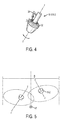
- the heads 18-1, 18-2 each consist of a rotating disc 32 and a controlled flow nozzle 34.
- This nozzle 34 is oriented towards the available annular portion of the rotating disk 32.
- the distribution pressure is 2 bars to give an order of magnitude.
- the disc 32 rotates at a speed between 3500 and 4500 revolutions / min and the generated drops are between 300 and 1200 microns.
- the disc 32 carries grooves so as to provide better projection and has a straight edge so as to release the droplets without restraint.
- the rotating disk 32 is also conical with a conicity oriented towards the projection zone that is to say the top of the cone oriented upwards.
- the axis ZZ 'of rotation of each disk 32 thus rotating from each head 18-1, 18-2, is inclined.
- the inclination ⁇ / 2 is formed in two planes perpendicular to the plane containing the shaft 14 and the ramp 16.
- the inclination is arranged in one direction, the clockwise directions for the first head 18-1, and in the opposite direction of the clockwise for the second head 18-2.
- the angle ⁇ is 8 °.
- Each of the heads projects droplets on a dispersion area having the shape of a disc and as the discs are inclined, the intersection of these discs with the ground leads to a distribution zone following two ellipses with an intersection between these two ellipses , thus ensuring a central covering and a covering of the surface to the right of each head.
- the devices of the prior art saw the surface located at the right of each head disadvantage, since the projection is obtained by centrifugal effect.
- the distribution related to the device according to the present invention is represented on the figure 5 .
Landscapes
- Life Sciences & Earth Sciences (AREA)
- Engineering & Computer Science (AREA)
- Insects & Arthropods (AREA)
- Pest Control & Pesticides (AREA)
- Wood Science & Technology (AREA)
- Zoology (AREA)
- Environmental Sciences (AREA)
- Mechanical Engineering (AREA)
- Catching Or Destruction (AREA)
Abstract
L'objet de l'invention est un dispositif de pulvérisation à rampe (16), comprenant un châssis (10) muni d'un arbre (14) rotatif débouchant sous ledit châssis (10) dans l'espace de travail confiné par des moyens (26) de confinement, caractérisé en ce que l'arbre (14) porte une rampe (16) munie de deux têtes (18-1, 18-2) de pulvérisation.The object of the invention is a ramp spray device (16), comprising a frame (10) provided with a rotating shaft (14) opening under said frame (10) in the confined work space by means (26) confinement, characterized in that the shaft (14) carries a ramp (16) provided with two heads (18-1, 18-2) for spraying.
Description
La présente invention concerne un dispositif de pulvérisation à rampe.The present invention relates to a boom spray device.
La description qui va suivre est effectuée pour une application en viticulture mais elle trouverait application pour tout type de cultures notamment développées en rangs.The following description is made for an application in viticulture but it would find application for all types of crops including developed rows.
Durant le cycle de culture, les exploitants sont conduits à traiter les végétaux pour lutter contre certaines maladies ou pour éradiquer de façon sélective certaines variétés de plantes. C'est le cas notamment pour le traitement du sol, et notamment le désherbage.During the crop cycle, farmers are led to treat plants to control certain diseases or to selectively eradicate certain plant varieties. This is particularly the case for soil treatment, including weeding.
Les produits ont évolué et ne présentent plus la toxicité passée mais ils n'en restent pas moins qu'il s'agit de produits à effets puissants qu'il convient de ne pas disséminer et surtout il convient de ne pas appliquer de ce produit sur les plants cultivés par exemple lorsqu'il s'agit de désherbant, ce qui affecterait bien sûr l'intégrité dudit plant.The products have evolved and no longer present the past toxicity but they are nonetheless that they are powerful products that should not be disseminated and especially should not be applied to this product. plants grown for example when it comes to weedkiller, which would affect of course the integrity of said plant.
Les règles sanitaires et le bon sens écologique obligent à protéger l'opérateur qui assure la mission de pulvérisation d'une part et l'environnement d'autre part.The sanitary rules and the good environmental sense oblige to protect the operator who ensures the mission of spraying on the one hand and the environment on the other hand.
A cet effet, la pulvérisation nécessite un ciblage de l'action et simultanément un dosage approprié sur la zone ciblée.For this purpose, the spraying requires a targeting of the action and simultaneously an appropriate dosage on the targeted area.
Une autre contrainte est également la couverture de la surface traitée car le diamètre des gouttelettes est important et leur répartition aussi.Another constraint is also the coverage of the treated surface because the diameter of the droplets is important and their distribution too.
Le cas des désherbants systémiques est particulièrement exemplifiant.The case of systemic herbicides is particularly exemplary.
Si les gouttelettes sont de faible diamètre et surtout présentent une répartition adaptée, l'efficacité sera grandement améliorée et nécessitera un volume moindre de produit pour un résultat plus exhaustif.If the droplets are of small diameter and especially have a suitable distribution, the efficiency will be greatly improved and will require a smaller volume of product for a more comprehensive result.
Cet objectif est relativement complexe et difficile à atteindre du fait que l'application ne s'effectue pas en laboratoire mais en plein champ avec les contraintes associées.This objective is relatively complex and difficult to achieve because the application is not carried out in the laboratory but in the field with the associated constraints.
C'est ainsi que la surface du sol par exemple n'est pas rigoureusement plane bien entendu. La culture en rangs par exemple montre la présence d'obstacles tels que les plants et éventuellement les palissages associés.This is how the surface of the ground for example is not rigorously flat of course. The cultivation in rows for example shows the presence of obstacles such as plants and possibly associated trellises.
Les conditions atmosphériques sont également une contrainte et notamment le vent, si bien qu'il faut protéger la pulvérisation afin que les gouttelettes ne se dispersent pas dans l'atmosphère et sur les endroits non souhaités.Atmospheric conditions are also a constraint, especially the wind, so the spray must be protected so that the droplets do not disperse into the atmosphere and undesired areas.
Le milieu agricole nécessite aussi une construction qui reste simple afin de conférer au dispositif la fiabilité nécessaire pour pouvoir agir, or les fenêtres météorologiques sont rares et il faut pouvoir agir sans risque de panne.The agricultural environment also requires a construction which remains simple in order to give the device the reliability necessary to be able to act, but the meteorological windows are rare and it is necessary to be able to act without risk of failure.
Au pire, si une panne arrivait, il faut que le dispositif soit vite réparé.At worst, if a failure happened, it must be quickly repaired.
Une autre contrainte est également la vitesse de travail, car les fenêtres météorologiques étant étroites ainsi qu'indiqué, il faut pouvoir agir vite mais en même temps si la vitesse augmente il faut pouvoir distribuer des volumes importants sans pour autant sacrifier à la bonne répartition, sans manque de diffusion car il n'est prévu qu'un passage donc l'exhaustivité de traitement de la surface est un impératif.Another constraint is also the speed of work, because the weather windows being narrow as indicated, it is necessary to be able to act quickly but at the same time if the speed increases it is necessary to be able to distribute large volumes without sacrificing to the good distribution, without lack of diffusion because it is expected that a passage so the completeness of treatment of the surface is an imperative.
On connaît des dispositifs de pulvérisation, notamment la demande internationale de brevet
La pulvérisation est obtenue par projection du liquide de traitement par une buse sur un disque rotatif.Spraying is achieved by spraying the process liquid through a nozzle on a rotating disc.
Un tel dispositif est une base mais la distribution mono buse est limitée et la répartition n'est pas homogène car elle provient du déplacement en translation d'une projection unique annulaire. Les mouvements du terrain notamment conduisent nécessairement à des manques ou pour le moins à des dosages variables.Such a device is a base but the single nozzle distribution is limited and the distribution is not homogeneous because it comes from the displacement in translation of a single annular projection. The movements of the terrain in particular necessarily lead to gaps or at least variable dosages.
Enfin, la vitesse de travail est limitée du fait que le débit ne peut être que limité du fait de la buse unique.Finally, the working speed is limited because the flow can only be limited because of the single nozzle.
Le dispositif selon la présente invention permet de pallier ces problèmes en proposant un dispositif à fort débit donc autorisant une vitesse de travail élevée, des moyens de pulvérisation croisée de façon à assurer une homogénéité de couverture de la zone de travail même à vitesse élevée. Le dispositif selon la présente invention permet aussi de pulvériser des liquides à forte viscosité.The device according to the present invention makes it possible to overcome these problems by proposing a device with a high flow rate thus allowing a high working speed, means of cross-spraying so as to ensure homogeneity of coverage of the working area even at high speed. The device according to the present invention also makes it possible to spray liquids with a high viscosity.
Le dispositif selon la présente invention est maintenant décrit en détail suivant un mode de réalisation particulier, non limitatif, les dessins annexés permettant d'exemplifier ledit dispositif et les figures de ces dessins montrent :
-
Figure 1 , une vue extérieure du dispositif et ses moyens de fixation sur une machine agricole, en l'absence de la jupe périphérique, -
Figure 2 : une vue en perspective du dispositif selon la présente invention, -
Figure 3 : une vue en élévation latérale du dispositif selon la présente invention, en l'absence de la jupe périphérique de façon à montrer l'angulation des buses, -
Figure 4 : une vue de détail d'une buse, -
Figure 5 : une vue du schéma de projection croisée des buses.
-
Figure 1 an external view of the device and its attachment means on an agricultural machine, in the absence of the peripheral skirt, -
Figure 2 : a perspective view of the device according to the present invention, -
Figure 3 a side elevational view of the device according to the present invention, in the absence of the peripheral skirt so as to show the angulation of the nozzles, -
Figure 4 : a detail view of a nozzle, -
Figure 5 : a view of the cross projection scheme of the nozzles.
Le dispositif est décrit en regard des différentes figures indifféremment.The device is described with regard to the different figures indifferently.
Sur la
Ce châssis 10 comporte un arbre 14 disposé en position centrale par rapport au châssis 10. Cet arbre 14 porte à son extrémité une rampe 16 avec deux têtes 18-1 et 18-2 de pulvérisation.This
Un palier 20, avec possibilité de blocage en orientation, permet le montage de l'arbre 14 par rapport au châssis.A
Des moyens 22 de protection mécanique de la rampe 16 sont également ménagés et supportés par le châssis 10. Ces moyens 22 de protection mécanique comprennent un ergot 24, disposé en amont par rapport au sens de déplacement montré par la flèche F, la forme permettant le passage de la rampe 16 en cas de rotation.Means 22 for mechanical protection of the
En complément du dispositif de pulvérisation à rampe, il est prévu des moyens 26 de confinement de la pulvérisation à l'intérieur et de protection de la pulvérisation vis-à-vis des turbulences extérieures. Ces moyens de confinement permettent de ménager un espace de travail confiné, sous le châssis. Ces moyens 26 de confinement sont en l'occurrence constitués d'une crinière 28 périphérique comportant des fibres fines, multiples, susceptibles d'épouser la forme du terrain, les obstacles et de ne pas laisser diffuser les produits pulvérisés.In addition to the ramp spray device, means 26 for confining the spray inside and for protecting the spray against external turbulence are provided. These containment means allow to provide a confined work space, under the frame. These containment means 26 consist in this case of a
La rampe plus particulièrement détaillée sur les
La rampe a son axe longitudinal disposé perpendiculairement à la direction d'avancement symbolisée par la flèche F.The ramp has its longitudinal axis arranged perpendicular to the direction of travel symbolized by the arrow F.
Les têtes 18-1, 18-2 sont constituées chacune d'un disque 32 tournant et d'une buse 34 à débit contrôlé.The heads 18-1, 18-2 each consist of a rotating
Cette buse 34 est orientée vers la partie annulaire disponible du disque 32 tournant. La pression de distribution est de 2 bars pour donner un ordre de grandeur.This
Toujours pour donner un ordre d'idée, le disque 32 tourne à une vitesse comprise entre 3500 et 4500 tours/min et les gouttes générées sont comprises entre 300 et 1200 µm.Still to give an idea, the
De façon avantageuse, selon l'invention, le disque 32 porte des cannelures de façon à assurer une meilleure projection et possède un bord franc de façon à libérer les gouttelettes sans retenue.Advantageously, according to the invention, the
Le disque 32 tournant est également conique avec une conicité orientée vers la zone de projection c'est-à-dire le sommet du cône orienté vers le haut.The rotating
Selon une caractéristique particulière de la présente invention, l'axe ZZ' de rotation de chaque disque 32 tournant donc de chaque tête 18-1, 18-2, est incliné.According to a particular characteristic of the present invention, the axis ZZ 'of rotation of each
L'inclinaison α/2, comme montré sur la
En l'occurrence, l'angle α est de 8°.In this case, the angle α is 8 °.
Chacune des têtes projette des gouttelettes sur une zone de dispersion ayant la forme d'un disque et comme les disques sont inclinés, l'intersection de ces disques avec le sol conduit à une zone de répartition suivant deux ellipses avec une intersection entre ces deux ellipses, assurant ainsi un recouvrement central et une couverture de la surface au droit de chaque tête. Les dispositifs de l'art antérieur voyaient la surface située au droit de chaque tête défavorisé, dès lors que la projection est obtenue par effet centrifuge.Each of the heads projects droplets on a dispersion area having the shape of a disc and as the discs are inclined, the intersection of these discs with the ground leads to a distribution zone following two ellipses with an intersection between these two ellipses , thus ensuring a central covering and a covering of the surface to the right of each head. The devices of the prior art saw the surface located at the right of each head disadvantage, since the projection is obtained by centrifugal effect.
La répartition liée au dispositif selon la présente invention est représentée sur la
Claims (8)
Applications Claiming Priority (1)
| Application Number | Priority Date | Filing Date | Title |
|---|---|---|---|
| FR1461727A FR3029070A1 (en) | 2014-12-01 | 2014-12-01 | RAMP SPRAY DEVICE |
Publications (1)
| Publication Number | Publication Date |
|---|---|
| EP3028567A1 true EP3028567A1 (en) | 2016-06-08 |
Family
ID=52779757
Family Applications (1)
| Application Number | Title | Priority Date | Filing Date |
|---|---|---|---|
| EP15197379.9A Withdrawn EP3028567A1 (en) | 2014-12-01 | 2015-12-01 | Spraying device |
Country Status (2)
| Country | Link |
|---|---|
| EP (1) | EP3028567A1 (en) |
| FR (1) | FR3029070A1 (en) |
Cited By (1)
| Publication number | Priority date | Publication date | Assignee | Title |
|---|---|---|---|---|
| WO2021156125A1 (en) * | 2020-02-05 | 2021-08-12 | Bayer Aktiengesellschaft | Spray unit |
Citations (3)
| Publication number | Priority date | Publication date | Assignee | Title |
|---|---|---|---|---|
| AT369231B (en) * | 1980-08-28 | 1982-12-10 | Krobath Maschf Ferd | MOBILE SPRAYING DEVICE FOR WEED CONTROL |
| WO1993016589A1 (en) | 1992-02-25 | 1993-09-02 | Graham John Redway | Agricultural chemical distributor |
| FR2733439A1 (en) * | 1995-04-27 | 1996-10-31 | Balligand Sa | Circular panel for recovery of sprayed products used in treatment of vines |
-
2014
- 2014-12-01 FR FR1461727A patent/FR3029070A1/en active Pending
-
2015
- 2015-12-01 EP EP15197379.9A patent/EP3028567A1/en not_active Withdrawn
Patent Citations (3)
| Publication number | Priority date | Publication date | Assignee | Title |
|---|---|---|---|---|
| AT369231B (en) * | 1980-08-28 | 1982-12-10 | Krobath Maschf Ferd | MOBILE SPRAYING DEVICE FOR WEED CONTROL |
| WO1993016589A1 (en) | 1992-02-25 | 1993-09-02 | Graham John Redway | Agricultural chemical distributor |
| FR2733439A1 (en) * | 1995-04-27 | 1996-10-31 | Balligand Sa | Circular panel for recovery of sprayed products used in treatment of vines |
Cited By (1)
| Publication number | Priority date | Publication date | Assignee | Title |
|---|---|---|---|---|
| WO2021156125A1 (en) * | 2020-02-05 | 2021-08-12 | Bayer Aktiengesellschaft | Spray unit |
Also Published As
| Publication number | Publication date |
|---|---|
| FR3029070A1 (en) | 2016-06-03 |
Similar Documents
| Publication | Publication Date | Title |
|---|---|---|
| EP0514610B1 (en) | Method and apparatus for area fire protection | |
| EP0353132B1 (en) | Mobile apparatus for the treatment of arborescent plants | |
| US6497088B1 (en) | Rotary mower with liquid applicator | |
| WO2016207571A1 (en) | Spraying unit, compact spraying module including such a unit, and spraying and control system including a plurality of such modules | |
| EP0357744B1 (en) | Centrifugal spraying device with cyclone air flow | |
| EP2147588A1 (en) | Precision pneumatic seed drill | |
| EP3028567A1 (en) | Spraying device | |
| Jadav et al. | Spray of Chemicals as Affected by Different Parameters of Air Assisted Sprayer: A Review. | |
| US4172557A (en) | Air sprayer apparatus for vineyards and the like | |
| EP3726980B1 (en) | System and method for spraying a product, notably a plant-protection product | |
| EP2888941B1 (en) | Equipment for destroying turf | |
| US20110278030A1 (en) | Weeding method and apparatus | |
| FR2989250A1 (en) | Device for spraying/projecting plant protection product i.e. pesticide, on vine plant, has receiving pieces for receiving projection elements to project plant protection product or introduction elements to introduce product in air flow | |
| EP3912466B1 (en) | Assembly for agricultural spraying system comprising a damping device of a pendular downward spraying movement | |
| FR2905559A1 (en) | Phytosanitary products pulverizing device for treating wine, has central turbine facing flow divider distributing air flow in two descending tubular semi-arches surrounding two sides of plant to be treated | |
| FR3074014A1 (en) | MODULAR SPRAY LEG, EQUIPPED AGRICULTURAL SPRAYER, AND AIR CIRCULATION MODULE FOR SPRAY LEG | |
| WO2019063942A1 (en) | Dispersion aircraft | |
| EP3160225B1 (en) | Spray nozzle provided with an improved incorporator | |
| EP3162206B1 (en) | Device for treating vegetation in hedges, in rows or field crops, with phytopharmaceutical products, provided with means for retrieving said products | |
| EP3488692B1 (en) | Phytosanitary product recovery panel and spraying machine | |
| AU2012203646B2 (en) | A Sprinkler Protector | |
| Vieri et al. | RHEA project achievement: an innovative spray concept for pesticide application to tree crops equipping a fleet of autonomous robots. Report 1356 | |
| FR2805716A1 (en) | HANGER FOR AGRICULTURAL SPRAYING APPARATUS | |
| WO2004100658A1 (en) | Device for recovering sprayed products and equipped atomiser | |
| FR2892893A1 (en) | Treatment product spray gun for e.g. vineyard, has hollow tubular shaped arm with insert having housing in which spreading nozzles are fixed in order to withdraw nozzles with respect to external surface of arm |
Legal Events
| Date | Code | Title | Description |
|---|---|---|---|
| PUAI | Public reference made under article 153(3) epc to a published international application that has entered the european phase |
Free format text: ORIGINAL CODE: 0009012 |
|
| AK | Designated contracting states |
Kind code of ref document: A1 Designated state(s): AL AT BE BG CH CY CZ DE DK EE ES FI FR GB GR HR HU IE IS IT LI LT LU LV MC MK MT NL NO PL PT RO RS SE SI SK SM TR |
|
| AX | Request for extension of the european patent |
Extension state: BA ME |
|
| STAA | Information on the status of an ep patent application or granted ep patent |
Free format text: STATUS: THE APPLICATION HAS BEEN PUBLISHED |
|
| STAA | Information on the status of an ep patent application or granted ep patent |
Free format text: STATUS: THE APPLICATION IS DEEMED TO BE WITHDRAWN |
|
| 18D | Application deemed to be withdrawn |
Effective date: 20161209 |