EP3028536B1 - Stove top device - Google Patents
Stove top device Download PDFInfo
- Publication number
- EP3028536B1 EP3028536B1 EP14766214.2A EP14766214A EP3028536B1 EP 3028536 B1 EP3028536 B1 EP 3028536B1 EP 14766214 A EP14766214 A EP 14766214A EP 3028536 B1 EP3028536 B1 EP 3028536B1
- Authority
- EP
- European Patent Office
- Prior art keywords
- cookware
- heating
- control unit
- heating element
- heating elements
- Prior art date
- Legal status (The legal status is an assumption and is not a legal conclusion. Google has not performed a legal analysis and makes no representation as to the accuracy of the status listed.)
- Active
Links
- 238000010438 heat treatment Methods 0.000 claims description 456
- 230000008859 change Effects 0.000 claims description 28
- 230000006870 function Effects 0.000 claims description 14
- 230000006698 induction Effects 0.000 claims description 14
- 230000001419 dependent effect Effects 0.000 claims description 9
- 238000010411 cooking Methods 0.000 description 107
- 238000001514 detection method Methods 0.000 description 7
- 238000000034 method Methods 0.000 description 7
- 239000011159 matrix material Substances 0.000 description 6
- 230000008569 process Effects 0.000 description 4
- 230000000694 effects Effects 0.000 description 3
- 230000001105 regulatory effect Effects 0.000 description 3
- 230000003213 activating effect Effects 0.000 description 2
- 230000005291 magnetic effect Effects 0.000 description 2
- 230000003797 telogen phase Effects 0.000 description 2
- 239000004020 conductor Substances 0.000 description 1
- 230000001276 controlling effect Effects 0.000 description 1
- 230000009849 deactivation Effects 0.000 description 1
- 238000011161 development Methods 0.000 description 1
- 230000018109 developmental process Effects 0.000 description 1
- 230000005672 electromagnetic field Effects 0.000 description 1
- 238000005265 energy consumption Methods 0.000 description 1
- 230000005294 ferromagnetic effect Effects 0.000 description 1
- 230000005484 gravity Effects 0.000 description 1
- 230000002441 reversible effect Effects 0.000 description 1
Images


Classifications
-
- H—ELECTRICITY
- H05—ELECTRIC TECHNIQUES NOT OTHERWISE PROVIDED FOR
- H05B—ELECTRIC HEATING; ELECTRIC LIGHT SOURCES NOT OTHERWISE PROVIDED FOR; CIRCUIT ARRANGEMENTS FOR ELECTRIC LIGHT SOURCES, IN GENERAL
- H05B6/00—Heating by electric, magnetic or electromagnetic fields
- H05B6/02—Induction heating
- H05B6/06—Control, e.g. of temperature, of power
- H05B6/062—Control, e.g. of temperature, of power for cooking plates or the like
-
- H—ELECTRICITY
- H05—ELECTRIC TECHNIQUES NOT OTHERWISE PROVIDED FOR
- H05B—ELECTRIC HEATING; ELECTRIC LIGHT SOURCES NOT OTHERWISE PROVIDED FOR; CIRCUIT ARRANGEMENTS FOR ELECTRIC LIGHT SOURCES, IN GENERAL
- H05B2213/00—Aspects relating both to resistive heating and to induction heating, covered by H05B3/00 and H05B6/00
- H05B2213/03—Heating plates made out of a matrix of heating elements that can define heating areas adapted to cookware randomly placed on the heating plate
-
- H—ELECTRICITY
- H05—ELECTRIC TECHNIQUES NOT OTHERWISE PROVIDED FOR
- H05B—ELECTRIC HEATING; ELECTRIC LIGHT SOURCES NOT OTHERWISE PROVIDED FOR; CIRCUIT ARRANGEMENTS FOR ELECTRIC LIGHT SOURCES, IN GENERAL
- H05B2213/00—Aspects relating both to resistive heating and to induction heating, covered by H05B3/00 and H05B6/00
- H05B2213/05—Heating plates with pan detection means
Definitions
- the invention is based on a hob device according to the preamble of claim 1.
- a cooktop device namely an induction cooktop device, with two heating elements for heating set-up cookware and with a control unit which is intended to detect a first position of a cookware and to activate a first heating element assigned to the first position, has already been proposed .
- the documents EP 1 160 590 A1 , EP 2 211 591 A1 , FR 2 984 463 A1 and EP 2 166 290 A1 disclose cooktop devices according to the prior art.
- the object of the invention is, in particular, to provide a generic device with improved properties with regard to high flexibility and / or high comfort for an operator.
- the object is achieved by the features of claim 1, while advantageous refinements and developments of the invention can be found in the subclaims.
- the invention is based on a cooktop device, in particular an induction cooktop device, with at least two, in particular at least three, advantageously at least four, particularly advantageously at least six, preferably at least eight, heating elements, at least for heating up cooked dishes and with at least one control unit which is provided for this purpose to detect a first position of a cookware and to activate at least one first heating element assigned to the first position.
- a cooktop device in particular an induction cooktop device, with at least two, in particular at least three, advantageously at least four, particularly advantageously at least six, preferably at least eight, heating elements, at least for heating up cooked dishes and with at least one control unit which is provided for this purpose to detect a first position of a cookware and to activate at least one first heating element assigned to the first position.
- the control unit is provided to deactivate at least one first heating element assigned to the first position of the cookware and at least one second element assigned to the second position of the cookware To activate the heating element with a different heating power density than the at least one first heating element.
- a “heating element” is to be understood in particular to mean an element which is intended, at least in one operating state, to transmit at least a large part of electrical energy to a cookware, preferably through at least one base body forming a cooking surface, and / or electrical energy in heat convert to in particular to heat at least one set of cookware, preferably through at least one base body forming a cooking surface.
- the heating element is intended to transmit a power of at least 100 W, in particular at least 500 W, advantageously at least 1000 W, preferably at least 2000 W, in at least one operating state in which the heating element is connected to supply electronics.
- the heating element is designed as an induction heating element.
- An “induction heating element” is to be understood in particular as a wound electrical conductor through which high-frequency alternating current flows through in at least one operating state.
- the induction heating element is intended to convert electrical energy into an alternating magnetic field which is intended to cause eddy currents and / or magnetic reversal effects in a metallic, preferably at least partially ferromagnetic, cookware, which are converted into heat.
- the induction heating element is preferably provided to cause the cooking utensils to heat up.
- the induction heating element is preferably provided in the operating mode to convert electrical energy into electromagnetic field energy, which is ultimately converted into heat in a suitable cookware.
- the cooktop device has at least one base body, at least for setting up cookware.
- the base body at least essentially forms a cooking surface.
- a “control unit” is to be understood in particular as an electronic unit which is preferably at least partially integrated in a control and / or regulating unit of a hob and which is preferably provided to control and / or regulate at least the heating elements.
- the control unit preferably comprises a computing unit and in particular, in addition to the computing unit, a storage unit with a control and / or regulating program stored therein, which is intended to be executed by the computing unit.
- the cooktop device advantageously has at least one sensor unit, which is formed in particular by the heating elements themselves and is intended to detect cookware set up, in particular by measuring at least one inductance and / or at least one capacitance.
- the control unit is provided for evaluating measured values of the sensor unit, calculating at least one heating zone and determining heating elements which form this heating zone.
- the control unit is provided to provide a detected cooking utensil with a heating zone adapted in shape, size and / or position assign.
- control unit is provided to enable at least one detection of a set of cooking utensils by the sensor unit by activating at least one of the heating elements, in particular at least a large part of the, advantageously all heating elements.
- control unit is provided to effect at least regular detection of cookware set up, in particular by the sensor unit.
- control unit is intended to effect at least a "regular" detection of cookware that has been set up, it should in particular be understood that the control unit is intended to detect cookware that has been set up at intervals of less than 30 s, in particular 10 s, advantageously less than 5 s, particularly advantageously less than 1 s, preferably less than 0.1 s.
- control unit is intended to "effect" at least a regular detection of cooked dishes, the control unit is intended to mean at least a regular detection of cooked dishes by activating at least one of the, in particular to enable at least a large part of, advantageously, all heating elements.
- control unit in the event that a cooking utensil is set up, is intended to activate at least one first heating element assigned to a position of the cooking utensil set up.
- control unit in the event of a change from a first position of a set of cookware to a second position of the set of cookware, the control unit is provided to deactivate at least one heating element assigned to the first position and / or to activate at least one heating element assigned to the second position.
- the control unit is provided for at least one heating element which is in the activated state and which is in the first position of the cookware and the second position of the cookware Cookware is covered, with changed different heating power densities to become more reactive.
- the control unit is provided to activate at least one heating element that is in the deactivated state and / or at least one heating element that is in the activated state to be more reactive with changed different heating power density, in particular by at least one heating element assigned to the second position to activate.
- control unit is intended to "react" at least one heating element that is in the deactivated state with a different, different heating power density
- control unit is intended to convert the heating element that is in the activated state Condition is to change a heating power of the heating element while maintaining an activated state of the heating element and / or that the control unit is provided to deactivate the heating element which is in the activated state and then to reactivate the deactivated heating element with a different, different heating power density .
- the control unit is provided to deactivate the heating element, which is in the activated state and is operated with a first heating power density, and then to reactivate it with a second heating power density that differs from the first heating power density.
- the control unit is intended to deactivate at least one heating element assigned to the first position of the set of cookware and to activate at least one heating element which is separate from the first heating element, in particular in order to detect that it has been set up to enable at least one cookware, advantageously the cookware removed from the first position, by the sensor unit.
- a heating element “assigned” to a position of a cooking utensil is to be understood in particular to mean a heating element that is intended, at least in one operating state, to heat, in particular to heat, the cooking utensil that is in particular arranged at the position to which the heating element is assigned.
- the heating element assigned to the position is arranged at least essentially at the position.
- the heating element assigned to the position and the cookware set up at the position are separated by the base body.
- “Provided” is to be understood in particular to be specially programmed, designed and / or equipped. The fact that an object is provided for a specific function should in particular be understood to mean that the object fulfills and / or executes this specific function in at least one application and / or operating state.
- a high degree of flexibility and / or a high level of comfort for an operator can in particular be achieved by the configuration according to the invention.
- flexible positioning of cookware set up can be achieved.
- can low energy consumption can be achieved in one operating state. As a result, low costs can advantageously be achieved for an operator.
- control unit be provided to operate at least one heating element associated with a set of cookware depending on a position of the cookware with a different heating power density.
- control unit is provided to operate at least one heating element, which is assigned to a cookware set up at a first position, with a first heating power density.
- control unit is intended to operate at least one heating element which is assigned to a cookware set up in a second position, which differs in particular from the first position, with a second heating power density which differs from the first heating power density. This enables a high degree of flexibility to be achieved.
- a heating power density with which a set of cookware is to be heated can advantageously be achieved in a pleasantly simple manner by specifically setting the cookware at different positions.
- a change in heating power density can be achieved in a comfortable manner by moving the cookware.
- control unit be provided to operate the heating elements in a position-dependent manner with predefined, different heating power densities, at least in one operating mode.
- control unit is provided to advantageously assign at least one of the heating elements, in particular a large part of them, to a predefined heating power density which differs in particular from a predefined heating power density of further heating elements.
- a predefined, individual heating power density is stored in the memory unit of the control unit for at least one of, in particular a large part of, advantageously each of the heating elements.
- At least one predefined heating power density of at least one heating element can be changed by an operator, in particular before a cooking process is started and / or during a cooking process and / or after a cooking process has ended.
- the control unit is provided to change further heating power densities of further heating elements depending on a change in one of the predefined heating power densities of a first heating element depending on the change in the predefined heating power densities of the first heating element. Under the twist that the control unit does this It is intended to "assign" a heating power density to a heating element, in particular it should be understood that the control unit is intended to operate the heating element with the heating power density assigned to the heating element when the heating element is activated.
- control unit is intended to “operate” at least one heating element
- control unit is intended to control at least one supply electronics that supplies the heating element.
- the supply electronics comprise at least one inverter for supplying at least one heating element.
- control unit be provided, at least in one operating mode, to assign a higher heating power density to a heating element which is arranged in an area facing an operator than to a heating element which is arranged in an area facing away from an operator.
- control unit is provided, at least in one operating mode, to assign a heating element arranged in an area facing an operator to a lower heating power density than a heating element arranged in an area facing away from an operator.
- control unit is provided, at least in one operating mode, to assign a heating element, which is arranged in the area facing an operator, a maximum heating power density of all heating elements, in particular in comparison with other heating elements, to at least one cooking surface area.
- control unit is provided, in at least one operating mode, to assign a heating element, which is arranged in the area facing away from an operator, a lowest heating power density of all heating elements, in particular in comparison with other heating elements, to at least one cooking surface area.
- control unit is provided for assigning different heating power densities depending on a distance to the area facing an operator. A high level of comfort for an operator can thereby be achieved in particular.
- an operator can prepare food to be cooked in the area facing the operator.
- an operator can place cooked food to keep warm in the area facing away from the operator, in particular in to be able to continue cooking food comfortably in the area facing the operator.
- control unit be provided, depending on an operating input by means of at least one operating unit, between at least a first operating mode, in which the heating elements are operated in a position-dependent manner with predefined, different heating power densities, and at least a second operating mode, in which the Heating elements can be operated with independent heating power densities.
- heating power densities can be freely selected in the second operating mode, in particular while avoiding influencing further heating power densities of further heating elements.
- a first heating power density of a first heating element can be freely selected by an operating input by means of the operating unit.
- a second heating power density of a second heating element can be freely selected by an operator input by means of the operating unit, in particular while avoiding influencing the first heating power density of the first heating element.
- An “operator input” is to be understood in particular as an actuation of the operator control unit by an operator.
- a flexible configuration can be achieved.
- an operator can advantageously conveniently switch between different operating modes at will.
- the hob device comprises at least two, in particular at least four, advantageously at least six, particularly advantageously at least ten, preferably at least twenty, particularly preferably at least thirty and advantageously a plurality of heating elements which advantageously form a variable cooking surface area.
- control unit is intended to assign, at least in one operating mode, at least one heating element, which is arranged at least substantially in the center of a variable cooking surface area, to a higher heating power density than at least one heating element, which is located within at least one concentric one Web is arranged around the heating element, which is arranged at least essentially in a center of a variable cooking surface area.
- a focus and / or a center of the variable should in particular
- Cooking surface area are understood, in particular when projecting the variable cooking surface area into a plane advantageously aligned parallel to a main extension plane of the base body.
- a "main plane of extent" of a structural unit is to be understood in particular as a plane which is parallel to a largest side surface of a smallest geometric cuboid, which still just completely surrounds the structural unit, and in particular runs through the center of the cuboid.
- the phrase that a heating element is arranged “at least essentially” in a center of a variable cooking surface area is to be understood in particular to mean that the heating element has a smallest distance in a comparison with other heating elements which, in particular together with the heating element, define the variable cooking surface area to the center of the variable cooktop area.
- At least one heating element is arranged "within" at least one concentric path around a center and / or around at least one further heating element is to be understood in particular to mean that the heating element is directly between a first concentric path and a second concentric path is arranged adjacent to the first concentric path and is at a greater distance from the center and / or from the further heating element than the first concentric path. In particular, this enables comfortable heating of a cooking utensil.
- control unit be provided, at least in one operating mode, to assign at least one heating element, which is at least partially covered by a cooking utensil, a higher heating power density than at least one heating element which is within at least one concentric path around the cooking utensil at least partially covered heating element is arranged.
- the phrase that the heating element is "at least partially" covered by a cookware is to be understood in particular to mean that the heating element is at least 30%, in particular at least 40%, advantageously at least 50%, particularly advantageously at least 60 % and preferably at least 70% of a main extension plane of the heating element is covered by the cookware.
- a good cooking result and / or a quick cooking process can thereby be achieved in particular. In particular, a high degree of flexibility can be achieved.
- control unit be provided, at least in one operating mode, for the heating elements in an oblique direction, which is connected to a Depth direction includes an angle between 10 ° and 80 °, in particular between 20 ° and 70 °, advantageously between 30 ° and 60 ° and preferably between 40 ° and 50 °, to assign different heating power densities.
- control unit is provided, at least in one operating mode, to assign different heating power densities to the heating elements in an oblique direction, which includes an angle between 0 ° and 90 ° with a depth direction.
- An angle “between ⁇ and ⁇ ” is to be understood in particular as an angular range which is spanned in particular by the angle ⁇ forming a first boundary and by the angle ⁇ forming a second boundary and advantageously comprises all angles within the boundaries with the exception of the two boundaries .
- a “depth direction” is to be understood in particular to mean a direction which, in an installed position, in particular of a hob comprising the hob device, is oriented from an area facing an operator into an area facing away from an operator. A high level of comfort for an operator can thereby be achieved in particular.
- control unit be provided to assign different heating power densities to the heating elements in an orthogonal direction, which is oriented perpendicular to a depth direction, at least in one operating mode.
- control unit is provided, in at least one operating mode, to assign at least one heating element, which is arranged in a first lateral area of the variable cooking surface area, a higher heating power density than at least one heating element, which is arranged in a second lateral area of the variable cooking area area, the first area of the variable cooking area area and the second area of the variable cooking area area are in particular arranged opposite one another and are advantageously spaced apart from one another in the orthogonal direction.
- control unit could in particular be provided, in at least one operating mode, to assign at least one heating element, which is arranged in the first lateral area of the variable cooking surface area, to a lower heating power density than at least one heating element, which is arranged in the second lateral area of the variable cooking area area.
- variable cooking surface area is to be understood in particular to mean a cooking surface area which is intended to form at least one cooking zone adapted to at least one set of cooking utensils.
- variable cooking surface area differs from a cooking surface in which heating zones are fixed, in particular by markings on the cooking surface.
- the variable cooking surface area is formed by at least two, in particular at least three, advantageously at least four heating elements.
- the heating elements forming the variable cooking surface area are arranged in a single row.
- a “row” is to be understood in particular as a row and / or a column and / or a stripe.
- the heating elements are arranged along one another, in particular lined up, along a longitudinal direction connecting the heating elements, which is in particular formed as a straight line.
- the longitudinal direction connects the focal points of the heating elements.
- the heating elements it is also conceivable for the heating elements to be arranged offset, the focal points of the heating elements being at a distance which is less than 50% from a straight line which is aligned at least substantially parallel to the longitudinal direction of the row and which connects the heating elements to one another at least substantially in the center. , in particular less than 40%, advantageously less than 30% of an amount of at least one extension, in particular a longitudinal extension and / or a transverse extension, of at least one of the heating elements forming the row.
- a "single" row of at least two heating elements is to be understood in particular to mean a row in which the heating elements are arranged adjacent, in particular precisely, to a row longitudinal direction, the control unit being provided to at least one of the heating elements arranged adjacent in the row longitudinal direction to form a cooking zone adapted to the cookware set up.
- at least one further heating element which is formed separately from the heating elements forming the row and is part of a further row formed separately from the row, is arranged spaced apart from each of the heating elements forming the row.
- the further heating element is at a distance from each of the heating elements forming the row with respect to a row transverse direction, which is oriented at least substantially perpendicular to the row longitudinal direction, which is greater than 15%, in particular greater than 30%, advantageously greater than 40%, preferably greater than 50%, particularly preferably greater than 75% of an amount of at least one extension, in particular a longitudinal extent and / or a transverse extent, at least one of the heating elements forming the row.
- a straight line and / or plane is oriented “at least substantially perpendicularly” to a further straight line and / or plane which is separate from the one straight line and / or plane is to be understood in particular to mean that the straight line and / or Plane with the further straight line and / or plane when projecting onto at least one projection plane, in which at least one of the straight lines and / or one of the planes is arranged, encloses an angle which is preferably less than 15 °, advantageously less than 10 ° and in particular deviates by less than 5 ° from an angle of 90 °.
- part, in particular essentially 50%, of a cooking surface is designed as a classic hob and a further part, in particular essentially 50%, of the cooking surface is designed as a variable cooking surface area. This enables a high degree of flexibility to be achieved.
- the heating elements forming the variable cooking surface area are arranged in the form of a hob matrix.
- a "hob matrix” is to be understood in particular to mean an arrangement of heating elements in which the heating elements are arranged in a mounting position, advantageously in a direction of gravity below the base body, in a regular grid, in particular in the form of rows and / or columns, in particular at least three of the heating elements are arranged in a row and in particular at least three of the heating elements in a column.
- a region which can be heated by means of the heating elements arranged in the form of a hob matrix, in particular a cooking surface comprises in particular at least 60%, advantageously at least 70%, particularly advantageously at least 80% and preferably at least 90% of a total surface of the heatable region. This enables a high degree of flexibility to be achieved.
- heating elements form a classic hob.
- at least two, in particular at least three, advantageously at least four of the heating elements form a classic hob.
- a “classic hob” is to be understood in particular as a cooking surface in which heating zones, which are each formed by at least one heating element, are fixed.
- the fixed heating zones could be marked the cooking surface is displayed to an operator.
- the heating zones are arranged at a distance from one another on the cooking surface.
- the heating zones are at a distance from one another which is greater than 15%, in particular greater than 30%, advantageously greater than 40%, preferably greater than 50%, particularly preferably greater than 75%, of an amount of at least one extension of at least one heating zone. In this way, an inexpensive configuration can be achieved in particular.
- Fig. 1 shows an inventive hob 28a, which is designed as an induction hob, with an inventive hob device 10a, which is designed as an induction hob device.
- the hob device 10a has a base body 30a for setting up cooking utensils 14a.
- the base body 30a forms a cooking surface.
- the hob device 10a comprises eight heating elements 12a for heating cookware 14a that has been set up. In 1 to 4 only one of the heating elements 12a is provided with a reference symbol for the sake of clarity.
- the heating elements 12a which are designed as induction heating elements, are arranged below the base body 30a.
- the heating elements 12a are each intended to heat cookware 14a placed on the base body 30a above the heating elements 12a.
- the heating elements 12a are designed as elongated heating elements 12a.
- Each heating element 12a has a longitudinal extent 32a, which is larger than a transverse extent 34a of the heating element 12a.
- variable cooking surface area 24a Each form a variable cooking surface area 24a.
- the two variable cooking surface areas 24a are arranged side by side.
- a first of the variable cooking surface areas 24a is arranged on a first side of the base body 30a.
- a second of the variable cooking surface areas 24a is on a second side of the base body 30a, which is opposite to the first side.
- the the variable Heating elements 12a forming cooking surface areas 24a are each arranged in a single row.
- the heating elements 12a forming the single row are arranged adjacent to one another with respect to a row longitudinal direction 36a.
- the row longitudinal direction 36a is aligned essentially perpendicular to the longitudinal extent 32a of the heating elements 12a.
- the row longitudinal direction 36a extends from a region of the base body 30a facing an operator in the installed state in the direction of a region of the base body 30a facing away from an operator in the installed state.
- the heating elements 12a forming the individual row are at a distance with respect to the row longitudinal direction 36a which is significantly smaller than the transverse extension 34a of the heating elements 12a, which is essentially parallel to the row longitudinal direction 36a.
- the cooktop device 10a comprises a sensor unit for detecting cookware 14a that has been set up.
- the sensor unit is essentially formed in one piece with the heating elements 12a and is intended to detect cookware 14a set up by measuring at least one inductance.
- the cooktop device 10a comprises a control unit 16a for controlling and regulating the heating elements 12a.
- the control unit 16a is connected to the sensor unit.
- the control unit 16a and the sensor unit are electrically connected.
- the control unit 16a is provided to combine heating elements 12a covered by the sensor unit of the cookware 14a that has been set up, as a function of a detection of the cookware 14a that has been set up, to form heating zones.
- the control unit 16a is provided to operate the heating elements 12a combined into heating zones.
- the sensor unit detects a first position 18a of a set of cookware 14a.
- the control unit 16a activates heating elements 12a assigned to the first position 18a of the cookware 14a.
- a set of cookware 14a covers a single heating element 12a - as shown in FIG Fig. 1 the control unit 16a activates the heating element 12a assigned to the first position 18a of the cookware 14a set up.
- the control unit 16a deactivates a first heating element 12a assigned to the first position 18a of the cookware 14a.
- the control unit 16 activates one assigned to the second position 20a of the cookware 14a second heating element 12a with a different heating power density than the first heating element 12a (cf. Fig. 2 ).
- the control unit 16a activates heating elements 12a associated with the first position 18a of the cookware 38a.
- the control unit 16a deactivates a first of the heating elements 12a associated with the first position 18a of the cookware 38a, which is in the first position 18a of the cookware 38a Cookware 38a is covered and is uncovered in the second position 20a of the cookware 38a.
- control unit 16a activates a second heating element 12a assigned to the second position 20a of the cooking utensil 38a, which is uncovered in the first position 18a of the cooking utensil 38a and is covered by the cooking utensil 38a in the second position 20a of the cooking utensil 38a, with a different heating power density than the first Heating element 12a (cf. Fig. 2 ).
- the control unit 16a reactivates a heating element 12a which is in the activated state and which is in the first position 18a of the cookware 38a and the second position 20a of the cookware 38a is covered by the cookware 38a with a different heating power density.
- a set of cookware covers more than two heating elements is analogous to this.
- the control unit 16a operates a heating element 12a associated with a set of cookware 14a, 38a, depending on a position 18a, 20a of the cookware 14a, 38a with a different heating power density.
- the control unit 16a operates the heating elements 12a with respect to the row longitudinal direction 36a with different heating power densities.
- the control unit 16a operates a heating element 12a arranged in an installed state in an area facing an operator with a different heating power density than a heating element 12a arranged in an installed state in an area facing away from an operator.
- the control unit 16a comprises a storage unit in which a heating power density is stored for each heating element 12a depending on a position of the heating element 12a.
- the control unit 16a operates in an operating mode the heating elements 12a are position-dependent with predefined, different heating power densities.
- a predefined heating power density of a heating element 12a arranged in the installed state in the area facing an operator is greater than a predefined heating power density of a heating element 12a arranged in the area facing away from an operator.
- the control unit 16a assigns a higher heating power density to a heating element 12a which is arranged in the region facing an operator than a heating element 12a which is arranged in the region facing away from an operator.
- the hob device 10a has a control unit 22a in the installed state for an operator to enter operating parameters.
- the control unit is provided for selecting and / or changing a heating zone.
- the control unit could be provided for setting a heating power and / or heating power density of a heating zone.
- the control unit is designed to select and / or change a cooking time and / or a cooking program.
- the operating unit is provided for changing an operating mode and / or operating state.
- further configurations of the operating unit and / or the operating parameter that appear to be useful to a person skilled in the art are conceivable.
- the cooktop device 10a has a control unit 16a which is provided to carry out actions and / or to change settings as a function of the operating parameters entered by means of the operating unit 22a.
- the control unit 16a changes a predefined heating power density of one of the heating elements 12a, which is stored in the storage unit, as a function of an operator input by means of the operating unit 22a.
- a predefined heating power density of a first heating element 12a changes, the control unit 16a changes heating power densities of the further three heating elements 12a, which together with the first heating element 12a form the variable cooking surface area 24a, depending on the change in the predefined heating power density of the first heating element 12a.
- control unit 16a changes as a function of an operating input by means of the operating unit 22a between the first operating mode, in which the heating elements 12a are operated in a position-dependent manner with predefined, different heating power densities, and a second one Operating mode in which the heating elements 12a are operated with independent heating power densities.
- a heating element 12a arranged in the area facing an operator in the installed state has a greatest predefined heating power density of the heating elements 12a forming the variable cooking surface area 24a.
- the heating power densities of the further heating elements 12a decrease in the direction of the row longitudinal direction 36a.
- the control unit 16a changes an assignment of the predefined, different heating power densities to the individual heating elements 12a.
- a heating element 12a arranged in the area facing an operator in the installed state has a smallest predefined heating power density of the heating elements 12a forming the variable cooking surface area 24a.
- the heating power densities of the further heating elements 12a increase in the direction of the row longitudinal direction 36a.
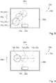
- Fig. 2 shows an inventive hob 28b, which is designed as an induction hob, with an inventive hob device 10b, which is designed as an induction hob device.
- the hob device 10b comprises four heating elements 12b for heating cookware 14a that has been set up.
- the heating elements 12b which are designed as induction heating elements, are arranged below a base body 30b.
- the heating elements 12b are designed as classic heating elements 12b.
- Two of the heating elements 12b are arranged one behind the other with respect to a row longitudinal direction 36b.
- the heating elements 12b form a classic hob 26b.
- the cooktop device 10b comprises a sensor unit for detecting cookware 14b that has been set up. In a method for operating the cooktop device 10b, the sensor unit detects a first position 18b of a set of cookware 14b.
- the cooktop device 10b comprises a control unit 16b which activates heating elements 12b associated with the first position 18b of the cookware 14b.
- the control unit 16b deactivates a first heating element 12b assigned to the first position 18b of the cookware 14a and activates a second heating element assigned to the second position 20b of the cookware 14b 12b with a different heating power density than the first heating element 12b (cf. Fig. 4 ).
- the control unit 16b operates a heating element 12b assigned to a set of cookware 14b in dependence on a position 18b, 20b of the cookware 14b with different heating power density.
- the control unit 16b operates the heating elements 12b with respect to the row longitudinal direction 36b with different heating power densities.
- the control unit 16b operates a heating element 12b arranged in an installed state in an area facing an operator with different heating power density than a heating element 12b arranged in an installed state in an area facing away from an operator.
- the control unit 16b comprises a storage unit in which a heating power density is stored for each heating element 12b depending on a position of the heating element 12b.
- the control unit 16b operates the heating elements 12b in a position-dependent manner with predefined, differing heating power densities.
- the control unit 16b assigns a heating element 12b to the area facing an operator is arranged, a higher heating power density than a heating element 12b, which is arranged in the area facing away from an operator.
- the control unit 16b changes a predefined heating power density of one of the heating elements 12b, which is stored in the storage unit, as a function of an operator input by means of an operating unit 22b.
- a predefined heating power density of a first heating element 12b changes
- the control unit 16b changes a heating power density of the further heating element 12b, which is arranged closest to the first heating element 12b with respect to the longitudinal direction 36b, as a function of the change in the predefined heating power density of the first heating element 12b.
- the control unit 16b changes an assignment of the predefined, differing heating power densities to the individual heating elements 12b.
- control unit 16b changes depending on an operating input by means of the operating unit 22b between the first operating mode, in which the heating elements 12b are operated depending on the position with predefined, different heating power densities, and a second operating mode, in which the heating elements 12b are operated with independent heating power densities will.
- Fig. 5 shows a hob 28c with a hob device 10c.
- the hob device 10c comprises a plurality of heating elements 12c for heating cookware 14c, 46c, 48c which has been set up.
- the heating elements 12c are arranged below a base body 30c.
- the base body 30c is designed as a hob plate.
- the heating elements 12c form a variable cooking surface area 24c.
- the heating elements 12c forming the variable cooking surface area 24c are arranged in the form of a hob matrix.
- the heating elements 12c are arranged in columns and rows.
- the term “matrix” is to be understood in the mathematical sense. In an alternative embodiment, it is conceivable that columns and / or rows of a hob matrix are arranged offset from one another. In 6 to 11 the heating elements 12c have been omitted for the sake of clarity.
- the cooktop device 10c comprises a control unit 16c which, in a method for operating a first position 18c of a set of cookware 14c, activates first heating elements 12c (cf. Fig. 6 ). In the event of a change from the first Position 18c of the cookware 14c to a second position 20c of the cookware 14c, the control unit 16c deactivates at least one first heating element 12c assigned to the first position 18c of the cookware 14c and activates at least one second heating element 12c assigned to the second position 20c of the cookware 14c with a different heating power density than that at least one first heating element 12c.
- control unit 16c reactivates at least one heating element 12c, which is in the activated state and which is covered by the cookware 14c in the first position 18c of the cookware 14c and the second position 20c of the cookware 14c, with a different, different heating power density.
- a case of a change from the second position 20c of the cookware 14c to a third position 42c of the cookware 14c is analogous to the case of a change from the first position 18c of the cookware 14c to the second position 20c of the cookware 14c.
- the control unit 16c operates heating elements 12c assigned to a cookware 14c that has been set up, depending on a position 18c, 20c, 42c of the cookware 14c with a different heating power density.
- the control unit 16c operates the heating elements 12c in the operating mode in a position-dependent manner with predefined, differing heating power densities.
- the control unit 16c changes the predefined heating power densities of the heating elements 12c as a function of an operator input by means of an operator unit 22c.
- a plurality of configurations of predefined heating power densities of the heating elements 12c are stored in a storage unit of the control unit 16c.
- a heating power density is assigned to the heating elements 12c depending on the position of the corresponding heating element 12c.
- an operator can create further configurations by means of an operator input using the operator unit.
- the control unit 16c maintains given predefined heating power densities of the heating elements 12c until a change in at least one heating power density of one of the heating elements 12c takes place by an operating input by means of the operating unit 22c.
- the control unit could maintain given predefined heating power densities of the heating elements 12c beyond a rest phase.
- the rest phase could occur, for example, due to a deactivation of the hob and / or a power failure and / or an emergency shutdown.
- the control unit 16c in the operating mode assigns a higher heating power density to heating elements 12c arranged in an area facing an operator than heating elements 12c arranged in an area facing away from an operator (cf. Fig. 6 ).
- a heating power density supplied to the cookware 14c in the operating mode can be reduced as a function of the position 18c, 20c, 42c of the cookware 14c (cf. Fig. 6 ).
- Such a change in a position 18c, 20c, 42c of the cookware 14c in the depth direction 40c could, for example, take place from the first position 18c of the cookware 14c to the third position 42c of the cookware 14c.
- the depth direction 40c is oriented from the area facing an operator in the direction of the area facing away from an operator.
- the control unit 16c operates a heating element 12c associated with the second position 20c of the cooking utensil 14c with a higher heating power density than one of the first position 18c the heating element 12c assigned to the cookware 14c (cf. Fig. 7 ).
- the control unit 16c When changing from the first position 18c of the cookware 14c to a third position 42c of the cookware 14c, the control unit 16c operates a heating element 12c assigned to the first position 18c of the cookware 14c with a higher heating power density than a heating element 12c assigned to the third position 42c of the cookware 14c.
- the third position 42c of the cooking utensil 14c is arranged in a direction which is oriented obliquely to the depth direction 40c and is directed toward the region facing away from an operator.
- a second cookware 46c is set up adjacent to the third position 42c of the cookware 14c
- the control unit 16c in the operating mode operates a heating element 12c, which is assigned to the second cookware 46c, with essentially the same heating power density as a heating element 12c, which is switched on the third position 42c of the cookware 14c is set up cookware 14c (cf. Fig. 7 ).
- a third cookware 48c is set up at substantially the same height as the second position 20c of the cookware 14c.
- the third cookware 48c is arranged adjacent to the second position 20c of the cookware 14c with respect to an orthogonal direction 44c.
- a distance of the third cookware 48c from a front edge of the base body 30c is substantially equal to a distance of the second position 20c of the cookware 14c from the front edge of the base body 30c.
- the control unit 16c operates a heating element 12c, which is assigned to the third cookware 14c, with essentially the same heating power density as a heating element 12c, which is assigned to the cookware 14c set up at the second position 20c of the cookware 14c.
- an operator changes the predefined heating power densities of the heating elements 12c by an operating input by means of the operating unit 22c and selects a second configuration.
- the control unit 16c assigns different heating power densities to the heating elements 12c in an oblique direction, which includes an angle between 10 ° and 80 ° with the depth direction 40c (cf. Fig. 8 ).
- the control unit 16c assigns a maximum heating power density to a first heating element 12c, which is arranged in the area facing an operator in a corner of the cooking surface area 24c.
- the control unit 16c assigns heating elements 12c, which are spaced in the depth direction 40c to the first heating element 12c, lower heating power densities than the first heating element 12c.
- the control unit 16c assigns heating elements 12c, which are spaced in an orthogonal direction 44c to the first heating element 12c, lower heating power densities than the first heating element 12c.
- the orthogonal direction 44c is aligned perpendicular to the depth direction 40c.
- a cookware 14c is set up in a vicinity of the first heating element 12c, which is arranged in the area facing a user in a corner of the cooking surface area 24c, at a first position 18c of the cookware 14c.
- the control unit 16c operates one of the first position 18c des Cooking element 14c assigned to cooking utensil 12c with a higher heating power density than a heating element 12c assigned to second position 20c of cooking utensil 14c (cf. Fig.
- the control unit 16c When changing from the second position 20c of the cooking utensil 14c to a third position 42c of the cooking utensil 14c in a second oblique direction, which includes an angle of substantially 55 ° with the depth direction 40c, the control unit 16c operates in the second position 20c the heating element 12c assigned to the cooking utensil 14c with a higher heating power density than a heating element 12c assigned to the third position 42c of the cooking utensil 14c.
- the control unit 16c changes the predefined heating power densities of the heating elements 12c in the operating mode. For example, in the operating mode, the control unit 16c assigns higher heating power densities to heating elements 12c which are arranged in a first lateral area of the variable cooking area area 24c than heating elements 12c which are arranged in a second lateral area of the variable cooking area area 24c (cf. Fig. 9 ).
- the first area of the variable cooktop area 24c and the second area of the variable cooktop area 24c are arranged opposite one another.
- the second area of the variable cooking surface area 24c is arranged in the orthogonal direction 44c at a distance from the first area of the variable cooking area area 24c.
- the control unit 16c operates a second heating element 12c, which in the orthogonal direction 44c is at a greater distance from the first lateral region of the variable cooking surface region 24c than a first heating element 12c, with a lower heating power density than the first heating element 12c.
- the control unit 16c operates the heating elements 12c as a function of the operating input by means of the operating unit 22c with position-dependent, predefined ones different heating power densities. For example, in the operating mode, the control unit 16c assigns a higher heating power density to a heating element 12c, which is arranged essentially in a center of the variable cooking surface area 24c, than heating elements 12c, which are arranged within concentric paths around what is essentially arranged in the center of the variable cooking surface area 24c Heating element 12c are arranged (cf. Fig. 10 ).
- the control unit 16c assigns a maximum heating power density to the heating element 12c which is arranged essentially in the center of the variable cooking surface area 24c.
- the control unit 16c assigns the same heating power density as that to heating elements 12c which are arranged within a first concentric path around the heating element 12c arranged essentially in the center of the variable cooking surface area 24c heating element 12c arranged essentially in the center of the variable cooking surface area 24c.
- the control unit 16c selects a radius of the first concentric path in a region of a diameter of the cookware 14c, which is set up on the heating element 12c arranged essentially in the center of the variable cooking surface region 24c (cf. Fig. 10 ).
- the control unit 16c assigns a lower heating power density to heating elements 12c which are arranged in a region between the first concentric path and a second concentric path which is directly adjacent to the first concentric path, than heating elements arranged within the first concentric path 12c.
- the control unit 16c assigns a heating element 12c which is arranged between two concentric tracks which are at a smaller distance from the heating element 12c which is essentially arranged in the center of the variable cooking surface area 24c than a heating element 12c which is arranged between two further concentric tracks is a greater heating power density than the heating element 12c, which is arranged between the two further concentric tracks.
- an operator selects a further configuration of the configurations stored in the memory unit of the control unit 16c by means of an operating input by means of the operating unit 22c.
- the control unit 16c assigns a higher heating power density to heating elements 12c, which are partially covered by a cooking utensil 14c, than heating elements 12c, which are arranged within concentric paths around the heating elements 12c partially covered by the cooking utensils 14c.
- the cookware 14c can be set up at any position 18c, 20c, 42c.
- the control unit 16c When setting up a second cookware 46c between a first concentric path around the cookware 14c and a second concentric path which is arranged directly adjacent to the first concentric path, the control unit 16c arranges one of the heating elements 12c, which are partially covered by the second cookware 46c lower heating power density than heating elements 12c, which are partially covered by the cookware 14c and are arranged in particular within the first concentric path. In the operating mode, the control unit 16c arranges heating elements 12c, that of a third cookware 48c, that between the second concentric path around the cookware 14c and a third concentric path that is directly adjacent to the second concentric path is partially covered, a lower heating power density than heating elements 12c, which are arranged between the first concentric path and the second concentric path.
Description
Die Erfindung geht aus von einer Kochfeldvorrichtung nach dem Oberbegriff des Anspruchs 1.The invention is based on a hob device according to the preamble of claim 1.
Es ist bereits eine Kochfeldvorrichtung, und zwar eine Induktionskochfeldvorrichtung, mit zwei Heizelementen zu einem Erhitzen von aufgestelltem Gargeschirr und mit einer Steuereinheit, die dazu vorgesehen ist, eine erste Position eines Gargeschirrs zu detektieren und ein der ersten Position zugeordnetes erstes Heizelement zu aktivieren, vorgeschlagen worden. Die Dokumenten
Die Aufgabe der Erfindung besteht insbesondere darin, eine gattungsgemäße Vorrichtung mit verbesserten Eigenschaften hinsichtlich einer hohen Flexibilität und/oder eines hohen Komforts für einen Bediener bereitzustellen. Die Aufgabe wird erfindungsgemäß durch die Merkmale des Patentanspruchs 1 gelöst, während vorteilhafte Ausgestaltungen und Weiterbildungen der Erfindung den Unteransprüchen entnommen werden können.The object of the invention is, in particular, to provide a generic device with improved properties with regard to high flexibility and / or high comfort for an operator. The object is achieved by the features of claim 1, while advantageous refinements and developments of the invention can be found in the subclaims.
Die Erfindung geht aus von einer Kochfeldvorrichtung, insbesondere einer Induktionskochfeldvorrichtung, mit zumindest zwei, insbesondere zumindest drei, vorteilhaft zumindest vier, besonders vorteilhaft zumindest sechs, vorzugsweise zumindest acht Heizelementen zumindest zu einem Erhitzen von aufgestelltem Gargeschirr und mit zumindest einer Steuereinheit, die dazu vorgesehen ist, eine erste Position eines Gargeschirrs zu detektieren und zumindest ein der ersten Position zugeordnetes erstes Heizelement zu aktivieren.The invention is based on a cooktop device, in particular an induction cooktop device, with at least two, in particular at least three, advantageously at least four, particularly advantageously at least six, preferably at least eight, heating elements, at least for heating up cooked dishes and with at least one control unit which is provided for this purpose to detect a first position of a cookware and to activate at least one first heating element assigned to the first position.
Es wird vorgeschlagen, dass die Steuereinheit für den Fall einer Änderung von der ersten Position des Gargeschirrs zu einer zweiten Position des Gargeschirrs dazu vorgesehen ist, zumindest ein der ersten Position des Gargeschirrs zugeordnetes erstes Heizelement zu deaktivieren und zumindest ein der zweiten Position des Gargeschirrs zugeordnetes zweites Heizelement mit unterschiedlicher Heizleistungsdichte als das zumindest eine erste Heizelement zu aktivieren. Unter einem "Heizelement" soll insbesondere ein Element verstanden werden, das dazu vorgesehen ist, zumindest in einem Betriebszustand elektrische Energie zumindest zu einem Großteil an ein Gargeschirr, vorzugsweise durch zumindest einen eine Kochfläche ausbildenden Grundkörper hindurch, zu übertragen und/oder elektrische Energie in Wärme umzuwandeln, um insbesondere zumindest ein aufgestelltes Gargeschirr, vorzugsweise durch zumindest einen eine Kochfläche ausbildenden Grundkörper hindurch, zu erhitzen. Insbesondere ist das Heizelement dazu vorgesehen, in zumindest einem Betriebszustand, in dem das Heizelement an eine Versorgungselektronik angeschlossen ist, eine Leistung von zumindest 100 W, insbesondere zumindest 500 W, vorteilhaft zumindest 1000 W, vorzugsweise zumindest 2000 W zu übertragen. Insbesondere ist das Heizelement als ein Induktionsheizelement ausgebildet. Unter einem "Induktionsheizelement" soll insbesondere ein gewickelter elektrischer Leiter verstanden werden, der in zumindest einem Betriebszustand von hochfrequentem Wechselstrom durchflossen ist. Insbesondere ist das Induktionsheizelement dazu vorgesehen, elektrische Energie in ein magnetisches Wechselfeld umzuwandeln, das dazu vorgesehen ist, in einem metallischen, vorzugsweise zumindest teilweise ferromagnetischen, Gargeschirr Wirbelströme und/oder Ummagnetisierungseffekte hervorzurufen, die in Wärme umgewandelt werden. Vorzugsweise ist das Induktionsheizelement dazu vorgesehen, eine Erwärmung des Gargeschirrs zu verursachen. Vorzugsweise ist das Induktionsheizelement dazu vorgesehen, in dem Betriebsmodus elektrische Energie in elektromagnetische Feldenergie zu wandeln, die in einem geeigneten Gargeschirr letztendlich in Wärme gewandelt wird. Insbesondere weist die Kochfeldvorrichtung zumindest einen Grundkörper zumindest zu einem Aufstellen von Gargeschirr auf. Insbesondere bildet der Grundkörper zumindest im Wesentlichen eine Kochfläche aus. Unter einer "Steuereinheit" soll insbesondere eine elektronische Einheit verstanden werden, die vorzugsweise in einer Steuer- und/oder Regeleinheit eines Kochfelds zumindest teilweise integriert ist und die vorzugsweise dazu vorgesehen ist, zumindest die Heizelemente zu steuern und/oder zu regeln. Vorzugsweise umfasst die Steuereinheit eine Recheneinheit und insbesondere zusätzlich zur Recheneinheit eine Speichereinheit mit einem darin gespeicherten Steuer- und/oder Regelprogramm, das dazu vorgesehen ist, von der Recheneinheit ausgeführt zu werden. Vorteilhaft weist die Kochfeldvorrichtung zumindest eine Sensoreinheit auf, die insbesondere von den Heizelementen selbst gebildet ist, die dazu vorgesehen ist, aufgestelltes Gargeschirr insbesondere mittels Messung zumindest einer Induktivität und/oder zumindest einer Kapazität zu detektieren. Insbesondere ist die Steuereinheit dazu vorgesehen, Messwerte der Sensoreinheit auszuwerten, zumindest eine Heizzone zu berechnen und Heizelemente festzulegen, die diese Heizzone bilden. Insbesondere ist Steuereinheit dazu vorgesehen, einem detektierten Gargeschirr eine in Form, Größe und/oder Position angepasste Heizzone zuzuordnen. Insbesondere ist die Steuereinheit dazu vorgesehen, mittels Aktivierung zumindest eines der Heizelemente, insbesondere zumindest eines Großteils der, vorteilhaft aller Heizelemente zumindest eine Detektion eines aufgestellten Gargeschirrs durch die Sensoreinheit zu ermöglichen. Alternativ sind weitere, einem Fachmann als sinnvoll erscheinende Möglichkeiten zu einer Detektion von aufgestelltem Gargeschirr denkbar. Insbesondere ist die Steuereinheit dazu vorgesehen, zumindest eine regelmäßige Detektion von aufgestelltem Gargeschirr, insbesondere durch die Sensoreinheit, zu bewirken. Unter der Wendung, dass die Steuereinheit dazu vorgesehen ist, zumindest eine "regelmäßige" Detektion von aufgestelltem Gargeschirr zu bewirken, soll insbesondere verstanden werden, dass die Steuereinheit dazu vorgesehen ist, eine Detektion von aufgestelltem Gargeschirr in zeitlichen Abständen von weniger als 30 s, insbesondere 10 s, vorteilhaft von weniger als 5 s, besonders vorteilhaft von weniger als 1 s, vorzugsweise von weniger als 0,1 s zu bewirken. Unter der Wendung, dass die Steuereinheit dazu vorgesehen ist, zumindest eine regelmäßige Detektion von aufgestelltem Gargeschirr zu "bewirken", soll insbesondere verstanden werden, dass die Steuereinheit dazu vorgesehen ist, zumindest eine regelmäßige Detektion von aufgestelltem Gargeschirr durch eine Aktivierung zumindest eines der, insbesondere zumindest eines Großteils der, vorteilhaft aller Heizelemente zu ermöglichen. Insbesondere ist die Steuereinheit für den Fall eines Aufstellens eines Gargeschirrs dazu vorgesehen, zumindest ein einer Position des aufgestellten Gargeschirrs zugeordnetes erstes Heizelement zu aktivieren. Insbesondere ist die Steuereinheit für den Fall einer Änderung von einer ersten Position eines aufgestellten Gargeschirrs zu einer zweiten Position des aufgestellten Gargeschirrs dazu vorgesehen, zumindest ein der ersten Position zugeordnetes Heizelement zu deaktivieren und/oder zumindest ein der zweiten Position zugeordnetes Heizelement zu aktivieren. Insbesondere ist die Steuereinheit für den Fall einer Änderung von der ersten Position des Gargeschirrs zu der zweiten Position des Gargeschirrs dazu vorgesehen, zumindest ein Heizelement, das sich in aktiviertem Zustand befindet und das in der ersten Position des Gargeschirrs und der zweiten Position des Gargeschirrs von dem Gargeschirr bedeckt ist, mit veränderter unterschiedlicher Heizleistungsdichte zu reaktiveren. Insbesondere ist die Steuereinheit dazu vorgesehen, zumindest ein Heizelement, das sich in deaktiviertem Zustand befindet, zu aktiveren und/oder zumindest ein Heizelement, das sich in aktiviertem Zustand befindet, mit veränderter unterschiedlicher Heizleistungsdichte zu reaktiveren, insbesondere um zumindest ein der zweiten Position zugeordnetes Heizelement zu aktivieren. Unter der Wendung, dass die Steuereinheit dazu vorgesehen ist, zumindest ein Heizelement, das sich in deaktiviertem Zustand befindet, mit veränderter unterschiedlicher Heizleistungsdichte zu "reaktiveren", soll insbesondere verstanden werden, dass die Steuereinheit dazu vorgesehen ist, das Heizelement, das sich in aktiviertem Zustand befindet, unter Aufrechterhaltung eines aktivierten Zustands des Heizelements eine Heizleistung des Heizelements zu verändern und/oder dass die Steuereinheit dazu vorgesehen ist, das Heizelement, das sich in aktiviertem Zustand befindet, zu deaktivieren und anschließend das deaktivierte Heizelement mit veränderter unterschiedlicher Heizleistungsdichte erneut zu aktivieren. Insbesondere ist die Steuereinheit dazu vorgesehen, das Heizelement, das sich in aktiviertem Zustand befindet und mit einer ersten Heizleistungsdichte betrieben wird, zu deaktivieren und anschließend mit einer zweiten Heizleistungsdichte, die sich von der ersten Heizleistungsdichte unterscheidet, zu reaktivieren. Insbesondere ist die Steuereinheit für den Fall eines Entfernens eines aufgestellten Gargeschirrs von einer ersten Position dazu vorgesehen, zumindest ein der ersten Position des aufgestellten Gargeschirrs zugeordnetes Heizelement zu deaktivieren und zumindest ein von dem ersten Heizelement getrennt ausgebildetes Heizelement zu aktivieren, insbesondere um eine Detektion eines Aufstellens zumindest eines Gargeschirrs, vorteilhaft des von der ersten Position entfernten Gargeschirrs, durch die Sensoreinheit zu ermöglichen. Unter einem einer Position eines Gargeschirrs "zugeordneten" Heizelement soll insbesondere ein Heizelement verstanden werden, das dazu vorgesehen ist, zumindest in einem Betriebszustand das an der Position, der das Heizelement zugeordnet ist, aufgestellte, insbesondere angeordnete Gargeschirr zu erhitzen, insbesondere zu beheizen. Insbesondere ist das der Position zugeordnete Heizelement zumindest im Wesentlichen an der Position angeordnet. Insbesondere sind das der Position zugeordnete Heizelement und das an der Position aufgestellte Gargeschirr durch den Grundkörper getrennt. Unter "vorgesehen" soll insbesondere speziell programmiert, ausgelegt und/oder ausgestattet verstanden werden. Darunter, dass ein Objekt zu einer bestimmten Funktion vorgesehen ist, soll insbesondere verstanden werden, dass das Objekt diese bestimmte Funktion in zumindest einem Anwendungs- und/oder Betriebszustand erfüllt und/oder ausführt.It is proposed that, in the event of a change from the first position of the cookware to a second position of the cookware, the control unit is provided to deactivate at least one first heating element assigned to the first position of the cookware and at least one second element assigned to the second position of the cookware To activate the heating element with a different heating power density than the at least one first heating element. A “heating element” is to be understood in particular to mean an element which is intended, at least in one operating state, to transmit at least a large part of electrical energy to a cookware, preferably through at least one base body forming a cooking surface, and / or electrical energy in heat convert to in particular to heat at least one set of cookware, preferably through at least one base body forming a cooking surface. In particular, the heating element is intended to transmit a power of at least 100 W, in particular at least 500 W, advantageously at least 1000 W, preferably at least 2000 W, in at least one operating state in which the heating element is connected to supply electronics. In particular, the heating element is designed as an induction heating element. An “induction heating element” is to be understood in particular as a wound electrical conductor through which high-frequency alternating current flows through in at least one operating state. In particular, the induction heating element is intended to convert electrical energy into an alternating magnetic field which is intended to cause eddy currents and / or magnetic reversal effects in a metallic, preferably at least partially ferromagnetic, cookware, which are converted into heat. The induction heating element is preferably provided to cause the cooking utensils to heat up. The induction heating element is preferably provided in the operating mode to convert electrical energy into electromagnetic field energy, which is ultimately converted into heat in a suitable cookware. In particular, the cooktop device has at least one base body, at least for setting up cookware. In particular, the base body at least essentially forms a cooking surface. A “control unit” is to be understood in particular as an electronic unit which is preferably at least partially integrated in a control and / or regulating unit of a hob and which is preferably provided to control and / or regulate at least the heating elements. The control unit preferably comprises a computing unit and in particular, in addition to the computing unit, a storage unit with a control and / or regulating program stored therein, which is intended to be executed by the computing unit. The cooktop device advantageously has at least one sensor unit, which is formed in particular by the heating elements themselves and is intended to detect cookware set up, in particular by measuring at least one inductance and / or at least one capacitance. In particular, the control unit is provided for evaluating measured values of the sensor unit, calculating at least one heating zone and determining heating elements which form this heating zone. In particular, the control unit is provided to provide a detected cooking utensil with a heating zone adapted in shape, size and / or position assign. In particular, the control unit is provided to enable at least one detection of a set of cooking utensils by the sensor unit by activating at least one of the heating elements, in particular at least a large part of the, advantageously all heating elements. As an alternative, further possibilities for the detection of cookware that have been set up are considered conceivable to a person skilled in the art. In particular, the control unit is provided to effect at least regular detection of cookware set up, in particular by the sensor unit. By the phrase that the control unit is intended to effect at least a "regular" detection of cookware that has been set up, it should in particular be understood that the control unit is intended to detect cookware that has been set up at intervals of less than 30 s, in particular 10 s, advantageously less than 5 s, particularly advantageously less than 1 s, preferably less than 0.1 s. By the phrase that the control unit is intended to "effect" at least a regular detection of cooked dishes, the control unit is intended to mean at least a regular detection of cooked dishes by activating at least one of the, in particular to enable at least a large part of, advantageously, all heating elements. In particular, the control unit, in the event that a cooking utensil is set up, is intended to activate at least one first heating element assigned to a position of the cooking utensil set up. In particular, in the event of a change from a first position of a set of cookware to a second position of the set of cookware, the control unit is provided to deactivate at least one heating element assigned to the first position and / or to activate at least one heating element assigned to the second position. In particular, in the event of a change from the first position of the cookware to the second position of the cookware, the control unit is provided for at least one heating element which is in the activated state and which is in the first position of the cookware and the second position of the cookware Cookware is covered, with changed different heating power densities to become more reactive. In particular, the control unit is provided to activate at least one heating element that is in the deactivated state and / or at least one heating element that is in the activated state to be more reactive with changed different heating power density, in particular by at least one heating element assigned to the second position to activate. The phrase that the control unit is intended to "react" at least one heating element that is in the deactivated state with a different, different heating power density is to be understood in particular that the control unit is intended to convert the heating element that is in the activated state Condition is to change a heating power of the heating element while maintaining an activated state of the heating element and / or that the control unit is provided to deactivate the heating element which is in the activated state and then to reactivate the deactivated heating element with a different, different heating power density . In particular, the control unit is provided to deactivate the heating element, which is in the activated state and is operated with a first heating power density, and then to reactivate it with a second heating power density that differs from the first heating power density. In particular, in the event that a set of cookware is removed from a first position, the control unit is intended to deactivate at least one heating element assigned to the first position of the set of cookware and to activate at least one heating element which is separate from the first heating element, in particular in order to detect that it has been set up to enable at least one cookware, advantageously the cookware removed from the first position, by the sensor unit. A heating element “assigned” to a position of a cooking utensil is to be understood in particular to mean a heating element that is intended, at least in one operating state, to heat, in particular to heat, the cooking utensil that is in particular arranged at the position to which the heating element is assigned. In particular, the heating element assigned to the position is arranged at least essentially at the position. In particular, the heating element assigned to the position and the cookware set up at the position are separated by the base body. “Provided” is to be understood in particular to be specially programmed, designed and / or equipped. The fact that an object is provided for a specific function should in particular be understood to mean that the object fulfills and / or executes this specific function in at least one application and / or operating state.
Durch die erfindungsgemäße Ausgestaltung kann insbesondere eine hohe Flexibilität und/oder ein hoher Komfort für einen Bediener erreicht werden. Insbesondere kann eine flexible Positionierung von aufgestelltem Gargeschirr erreicht werden. Insbesondere kann in einem Betriebszustand ein geringer Energieverbrauch erreicht werden. Dadurch können vorteilhaft geringe Kosten für einen Bediener erreicht werden.A high degree of flexibility and / or a high level of comfort for an operator can in particular be achieved by the configuration according to the invention. In particular, flexible positioning of cookware set up can be achieved. In particular, can low energy consumption can be achieved in one operating state. As a result, low costs can advantageously be achieved for an operator.
Zudem wird vorgeschlagen, dass die Steuereinheit dazu vorgesehen ist, zumindest ein einem aufgestellten Gargeschirr zugeordnetes Heizelement in Abhängigkeit einer Position des Gargeschirrs mit unterschiedlicher Heizleistungsdichte zu betreiben. Insbesondere ist die Steuereinheit dazu vorgesehen, zumindest ein Heizelement, das einem an einer ersten Position aufgestellten Gargeschirr zugeordnet ist, mit einer ersten Heizleistungsdichte zu betreiben. Erfindungsgemäß ist die Steuereinheit dazu vorgesehen, zumindest ein Heizelement, das einem an einer zweiten Position, die sich insbesondere von der ersten Position unterscheidet, aufgestellten Gargeschirr zugeordnet ist, mit einer zweiten Heizleistungsdichte zu betreiben, die sich von der ersten Heizleistungsdichte unterscheidet. Dadurch kann insbesondere ein hohes Maß an Flexibilität erreicht werden. Zudem kann vorteilhaft eine Heizleistungsdichte, mit welcher ein aufgestelltes Gargeschirr beheizt werden soll, in angenehm einfacher Weise durch gezieltes Aufstellen des Gargeschirrs an unterschiedlichen Positionen erreicht werden. Insbesondere kann eine Änderung einer Heizleistungsdichte in komfortabler Weise durch Verschieben des Gargeschirrs erreicht werden.In addition, it is proposed that the control unit be provided to operate at least one heating element associated with a set of cookware depending on a position of the cookware with a different heating power density. In particular, the control unit is provided to operate at least one heating element, which is assigned to a cookware set up at a first position, with a first heating power density. According to the invention, the control unit is intended to operate at least one heating element which is assigned to a cookware set up in a second position, which differs in particular from the first position, with a second heating power density which differs from the first heating power density. This enables a high degree of flexibility to be achieved. In addition, a heating power density with which a set of cookware is to be heated can advantageously be achieved in a pleasantly simple manner by specifically setting the cookware at different positions. In particular, a change in heating power density can be achieved in a comfortable manner by moving the cookware.
Weiterhin wird vorgeschlagen, dass die Steuereinheit dazu vorgesehen ist, zumindest in einem Betriebsmodus die Heizelemente positionsabhängig mit vordefinierten, sich voneinander unterscheidenden Heizleistungsdichten zu betreiben. Insbesondere ist die Steuereinheit dazu vorgesehen, zumindest einem der, insbesondere einem Großteil der, vorteilhaft jedem der Heizelemente eine vordefinierte Heizleistungsdichte zuzuordnen, die sich insbesondere von einer vordefinierten Heizleistungsdichte weiterer Heizelemente unterscheidet. Insbesondere ist in der Speichereinheit der Steuereinheit zu zumindest einem der, insbesondere einem Großteil der, vorteilhaft jedem der Heizelemente eine vordefinierte, individuelle Heizleistungsdichte gespeichert. Insbesondere ist zumindest eine vordefinierte Heizleistungsdichte zumindest eines Heizelements von einem Bediener veränderbar, insbesondere vor Start eines Garvorgangs und/oder während eines Garvorgangs und/oder nach Beendigung eines Garvorgangs. Insbesondere ist die Steuereinheit dazu vorgesehen, in Abhängigkeit einer Änderung einer der vordefinierten Heizleistungsdichten eines ersten Heizelements weitere Heizleistungsdichten weiterer Heizelemente in Abhängigkeit von der Änderung der vordefinierten Heizleistungsdichten des ersten Heizelements verändern. Unter der Wendung, dass die Steuereinheit dazu vorgesehen ist, einem Heizelement eine Heizleistungsdichte "zuzuordnen", soll insbesondere verstanden werden, dass die Steuereinheit dazu vorgesehen ist, bei einer Aktivierung des Heizelements das Heizelement mit der Heizleistungsdichte zu betreiben, die dem Heizelement zugeordnet ist. Unter der Wendung, dass die Steuereinheit dazu vorgesehen ist, zumindest ein Heizelement zu "betreiben", soll insbesondere verstanden werden, dass die Steuereinheit dazu vorgesehen ist, zumindest eine Versorgungselektronik anzusteuern, die das Heizelement versorgt. Insbesondere umfasst die Versorgungselektronik zumindest einen Wechselrichter zu einer Versorgung zumindest eines Heizelements. Dadurch kann insbesondere ein hoher Komfort für einen Bediener erreicht werden, der mittels einer Änderung einer Position des Gargeschirrs eine Änderung einer Heizleistungsdichte des Gargeschirrs verändern kann.It is further proposed that the control unit be provided to operate the heating elements in a position-dependent manner with predefined, different heating power densities, at least in one operating mode. In particular, the control unit is provided to advantageously assign at least one of the heating elements, in particular a large part of them, to a predefined heating power density which differs in particular from a predefined heating power density of further heating elements. In particular, a predefined, individual heating power density is stored in the memory unit of the control unit for at least one of, in particular a large part of, advantageously each of the heating elements. In particular, at least one predefined heating power density of at least one heating element can be changed by an operator, in particular before a cooking process is started and / or during a cooking process and / or after a cooking process has ended. In particular, the control unit is provided to change further heating power densities of further heating elements depending on a change in one of the predefined heating power densities of a first heating element depending on the change in the predefined heating power densities of the first heating element. Under the twist that the control unit does this It is intended to "assign" a heating power density to a heating element, in particular it should be understood that the control unit is intended to operate the heating element with the heating power density assigned to the heating element when the heating element is activated. The phrase that the control unit is intended to “operate” at least one heating element is to be understood in particular to mean that the control unit is intended to control at least one supply electronics that supplies the heating element. In particular, the supply electronics comprise at least one inverter for supplying at least one heating element. As a result, a high level of convenience can be achieved for an operator who can change a change in the heating power density of the cooking utensil by changing a position of the cooking utensil.
Ferner wird vorgeschlagen, dass die Steuereinheit dazu vorgesehen ist, zumindest in einem Betriebsmodus einem Heizelement, das in einem einem Bediener zugewandten Bereich angeordnet ist, eine höhere Heizleistungsdichte zuzuordnen als einem Heizelement, das in einem einem Bediener abgewandten Bereich angeordnet ist. Alternativ ist denkbar, dass die Steuereinheit dazu vorgesehen ist, zumindest in einem Betriebsmodus einem Heizelement, das in einem einem Bediener zugewandten Bereich angeordnet ist, eine niedere Heizleistungsdichte zuzuordnen als einem Heizelement, das in einem einem Bediener abgewandten Bereich angeordnet ist. Insbesondere ist die Steuereinheit dazu vorgesehen, zumindest in einem Betriebsmodus einem Heizelement, das in dem einem Bediener zugewandten Bereich angeordnet ist, eine höchste Heizleistungsdichte aller Heizelemente, insbesondere in einem Vergleich mit weiteren Heizelementen, zumindest eines Kochflächenbereichs zuzuordnen. Insbesondere ist die Steuereinheit dazu vorgesehen, zumindest in einem Betriebsmodus einem Heizelement, das in dem einem Bediener abgewandten Bereich angeordnet ist, eine geringste Heizleistungsdichte aller Heizelemente, insbesondere in einem Vergleich mit weiteren Heizelementen, zumindest eines Kochflächenbereichs zuzuordnen. Insbesondere ist die Steuereinheit dazu vorgesehen, Heizelementen in Abhängigkeit von einer Entfernung zu dem einem Bediener zugewandten Bereich unterschiedliche Heizleistungsdichten zuzuordnen. Dadurch kann insbesondere ein hoher Komfort für einen Bediener erreicht werden. Insbesondere kann ein Bediener in dem dem Bediener zugewandten Bereich Gargut zubereiten. Zudem kann ein Bediener fertig zubereitetes Gargut zu einem Warmhalten in dem dem Bediener abgewandten Bereich platzieren, um insbesondere in dem dem Bediener zugewandten Bereich weiterhin komfortabel Gargut zubereiten zu können.It is further proposed that the control unit be provided, at least in one operating mode, to assign a higher heating power density to a heating element which is arranged in an area facing an operator than to a heating element which is arranged in an area facing away from an operator. Alternatively, it is conceivable that the control unit is provided, at least in one operating mode, to assign a heating element arranged in an area facing an operator to a lower heating power density than a heating element arranged in an area facing away from an operator. In particular, the control unit is provided, at least in one operating mode, to assign a heating element, which is arranged in the area facing an operator, a maximum heating power density of all heating elements, in particular in comparison with other heating elements, to at least one cooking surface area. In particular, the control unit is provided, in at least one operating mode, to assign a heating element, which is arranged in the area facing away from an operator, a lowest heating power density of all heating elements, in particular in comparison with other heating elements, to at least one cooking surface area. In particular, the control unit is provided for assigning different heating power densities depending on a distance to the area facing an operator. A high level of comfort for an operator can thereby be achieved in particular. In particular, an operator can prepare food to be cooked in the area facing the operator. In addition, an operator can place cooked food to keep warm in the area facing away from the operator, in particular in to be able to continue cooking food comfortably in the area facing the operator.
Zudem wird vorgeschlagen, dass die Steuereinheit dazu vorgesehen ist, in Abhängigkeit von einer Bedieneingabe mittels zumindest einer Bedieneinheit zwischen zumindest einem ersten Betriebsmodus, in welchem die Heizelemente positionsabhängig mit vordefinierten, sich voneinander unterscheidenden Heizleistungsdichten betrieben werden, und zumindest einem zweiten Betriebsmodus, in welchem die Heizelemente mit voneinander unabhängigen Heizleistungsdichten betrieben werden, zu wechseln. Insbesondere sind Heizleistungsdichten in dem zweiten Betriebsmodus frei wählbar, insbesondere unter Vermeidung einer Beeinflussung weiterer Heizleistungsdichten weiterer Heizelemente. Insbesondere ist in dem zweiten Betriebsmodus eine erste Heizleistungsdichte eines ersten Heizelements frei durch eine Bedieneingabe mittels der Bedieneinheit wählbar. Insbesondere ist in dem zweiten Betriebsmodus eine zweite Heizleistungsdichte eines zweiten Heizelements frei durch eine Bedieneingabe mittels der Bedieneinheit wählbar, insbesondere unter Vermeidung einer Beeinflussung der ersten Heizleistungsdichte des ersten Heizelements. Unter einer "Bedieneingabe" soll insbesondere eine Betätigung der Bedieneinheit durch einen Bediener verstanden werden. Dadurch kann insbesondere eine flexible Ausgestaltung erreicht werden. Zudem kann vorteilhaft ein Bediener nach Belieben komfortabel zwischen verschiedenen Betriebsmodi wechseln.In addition, it is proposed that the control unit be provided, depending on an operating input by means of at least one operating unit, between at least a first operating mode, in which the heating elements are operated in a position-dependent manner with predefined, different heating power densities, and at least a second operating mode, in which the Heating elements can be operated with independent heating power densities. In particular, heating power densities can be freely selected in the second operating mode, in particular while avoiding influencing further heating power densities of further heating elements. In particular, in the second operating mode, a first heating power density of a first heating element can be freely selected by an operating input by means of the operating unit. In particular, in the second operating mode, a second heating power density of a second heating element can be freely selected by an operator input by means of the operating unit, in particular while avoiding influencing the first heating power density of the first heating element. An “operator input” is to be understood in particular as an actuation of the operator control unit by an operator. As a result, a flexible configuration can be achieved. In addition, an operator can advantageously conveniently switch between different operating modes at will.
In einer weiteren Ausgestaltung wird vorgeschlagen, dass die Kochfeldvorrichtung zumindest zwei, insbesondere zumindest vier, vorteilhaft zumindest sechs, besonders vorteilhaft zumindest zehn, vorzugsweise zumindest zwanzig, besonders bevorzugt zumindest dreißig und vorteilhaft eine Vielzahl an Heizelementen umfasst, die vorteilhaft einen variablen Kochflächenbereich ausbilden.In a further embodiment it is proposed that the hob device comprises at least two, in particular at least four, advantageously at least six, particularly advantageously at least ten, preferably at least twenty, particularly preferably at least thirty and advantageously a plurality of heating elements which advantageously form a variable cooking surface area.
Weiterhin wird als nicht beanspruchter Ausführungsbeispiel vorgeschlagen, dass die Steuereinheit dazu vorgesehen ist, zumindest in einem Betriebsmodus zumindest einem Heizelement, das wenigstens im Wesentlichen in einem Zentrum eines variablen Kochflächenbereichs angeordnet ist, eine höhere Heizleistungsdichte zuzuordnen als zumindest einem Heizelement, das innerhalb wenigstens einer konzentrischen Bahn um das insbesondere wenigstens im Wesentlichen in einem Zentrum eines variablen Kochflächenbereichs angeordnete Heizelement angeordnet ist. Unter einem "Zentrum" eines variablen Kochflächenbereichs soll insbesondere ein Schwerpunkt und/oder ein Mittelpunkt des variablenFurthermore, it is proposed as an embodiment not claimed that the control unit is intended to assign, at least in one operating mode, at least one heating element, which is arranged at least substantially in the center of a variable cooking surface area, to a higher heating power density than at least one heating element, which is located within at least one concentric one Web is arranged around the heating element, which is arranged at least essentially in a center of a variable cooking surface area. Under a "center" of a variable cooking surface area, a focus and / or a center of the variable should in particular
Kochflächenbereichs verstanden werden, insbesondere bei einer Projektion des variablen Kochflächenbereichs in eine vorteilhaft parallel zu einer Haupterstreckungsebene des Grundkörpers ausgerichtete Ebene. Unter einer "Haupterstreckungsebene" einer Baueinheit soll insbesondere eine Ebene verstanden werden, welche parallel zu einer größten Seitenfläche eines kleinsten geometrischen Quaders ist, welcher die Baueinheit gerade noch vollständig umschließt, und insbesondere durch den Mittelpunkt des Quaders verläuft. Unter der Wendung, dass ein Heizelement "wenigstens im Wesentlichen" in einem Zentrum eines variablen Kochflächenbereichs angeordnet ist, soll insbesondere verstanden werden, dass das Heizelement in einem Vergleich mit weiteren Heizelementen, die insbesondere gemeinsam mit dem Heizelement den variablen Kochflächenbereich definieren, einen kleinsten Abstand zu dem Zentrum des variablen Kochflächenbereichs aufweist. Unter der Wendung, dass zumindest ein Heizelement "innerhalb" wenigstens einer konzentrischen Bahn um ein Zentrum und/oder um zumindest ein weiteres Heizelement angeordnet ist, soll insbesondere verstanden werden, dass das Heizelement zwischen einer ersten konzentrischen Bahn und einer zweiten konzentrischen Bahn, die direkt zu der ersten konzentrischen Bahn benachbart angeordnet ist und zu dem Zentrum und/oder zu dem weiteren Heizelement einen größeren Abstand aufweist als die erste konzentrische Bahn. Dadurch kann insbesondere eine komfortable Beheizung eines Gargeschirrs erreicht werden.Cooking surface area are understood, in particular when projecting the variable cooking surface area into a plane advantageously aligned parallel to a main extension plane of the base body. A "main plane of extent" of a structural unit is to be understood in particular as a plane which is parallel to a largest side surface of a smallest geometric cuboid, which still just completely surrounds the structural unit, and in particular runs through the center of the cuboid. The phrase that a heating element is arranged “at least essentially” in a center of a variable cooking surface area is to be understood in particular to mean that the heating element has a smallest distance in a comparison with other heating elements which, in particular together with the heating element, define the variable cooking surface area to the center of the variable cooktop area. The phrase that at least one heating element is arranged "within" at least one concentric path around a center and / or around at least one further heating element is to be understood in particular to mean that the heating element is directly between a first concentric path and a second concentric path is arranged adjacent to the first concentric path and is at a greater distance from the center and / or from the further heating element than the first concentric path. In particular, this enables comfortable heating of a cooking utensil.
Alternativ oder zusätzlich wird vorgeschlagen, dass die Steuereinheit dazu vorgesehen ist, zumindest in einem Betriebsmodus zumindest einem Heizelement, das wenigstens teilweise von einem Gargeschirr bedeckt ist, eine höhere Heizleistungsdichte zuzuordnen als zumindest einem Heizelement, das innerhalb wenigstens einer konzentrischen Bahn um das von dem Gargeschirr wenigstens teilweise bedeckte Heizelement angeordnet ist. Unter der Wendung, dass das Heizelement "wenigstens teilweise" von einem Gargeschirr bedeckt ist, soll insbesondere verstanden werden, dass das Heizelement zu einem Anteil von mindestens 30 %, insbesondere von mindestens 40 %, vorteilhaft von mindestens 50 %, besonders vorteilhaft von mindestens 60 % und vorzugsweise von mindestens 70 % einer Haupterstreckungsebene des Heizelements von dem Gargeschirr bedeckt ist. Dadurch kann insbesondere ein gutes Garergebnis und/oder ein schneller Garvorgang erreicht werden. Insbesondere kann eine hohe Flexibilität erreicht werden.As an alternative or in addition, it is proposed that the control unit be provided, at least in one operating mode, to assign at least one heating element, which is at least partially covered by a cooking utensil, a higher heating power density than at least one heating element which is within at least one concentric path around the cooking utensil at least partially covered heating element is arranged. The phrase that the heating element is "at least partially" covered by a cookware is to be understood in particular to mean that the heating element is at least 30%, in particular at least 40%, advantageously at least 50%, particularly advantageously at least 60 % and preferably at least 70% of a main extension plane of the heating element is covered by the cookware. A good cooking result and / or a quick cooking process can thereby be achieved in particular. In particular, a high degree of flexibility can be achieved.
Ferner wird vorgeschlagen, dass die Steuereinheit dazu vorgesehen ist, zumindest in einem Betriebsmodus den Heizelementen in einer Schrägrichtung, die mit einer Tiefenrichtung einen Winkel zwischen 10° und 80°, insbesondere zwischen 20° und 70°, vorteilhaft zwischen 30° und 60° und vorzugsweise zwischen 40° und 50° einschließt, unterschiedliche Heizleistungsdichten zuzuordnen. Alternativ ist denkbar, dass die Steuereinheit dazu vorgesehen ist, zumindest in einem Betriebsmodus den Heizelementen in einer Schrägrichtung, die mit einer Tiefenrichtung einen Winkel zwischen 0° und 90° einschließt, unterschiedliche Heizleistungsdichten zuzuordnen. Unter einem Winkel "zwischen α und β" soll insbesondere ein Winkelbereich verstanden werden, der insbesondere durch den eine erste Grenze bildenden Winkel α sowie durch den eine zweite Grenze bildenden Winkel β aufgespannt ist und vorteilhaft alle Winkel innerhalb der Grenzen mit Ausnahme der beiden Grenzen umfasst. Unter einer "Tiefenrichtung" soll insbesondere eine Richtung verstanden werden, die in einer Einbaulage insbesondere eines die Kochfeldvorrichtung umfassenden Kochfelds von einem einem Bediener zugewandten Bereich in einen einem Bediener abgewandten Bereich ausgerichtet ist. Dadurch kann insbesondere ein hoher Komfort für einen Bediener erreicht werden.It is further proposed that the control unit be provided, at least in one operating mode, for the heating elements in an oblique direction, which is connected to a Depth direction includes an angle between 10 ° and 80 °, in particular between 20 ° and 70 °, advantageously between 30 ° and 60 ° and preferably between 40 ° and 50 °, to assign different heating power densities. Alternatively, it is conceivable that the control unit is provided, at least in one operating mode, to assign different heating power densities to the heating elements in an oblique direction, which includes an angle between 0 ° and 90 ° with a depth direction. An angle “between α and β” is to be understood in particular as an angular range which is spanned in particular by the angle α forming a first boundary and by the angle β forming a second boundary and advantageously comprises all angles within the boundaries with the exception of the two boundaries . A “depth direction” is to be understood in particular to mean a direction which, in an installed position, in particular of a hob comprising the hob device, is oriented from an area facing an operator into an area facing away from an operator. A high level of comfort for an operator can thereby be achieved in particular.
Zudem wird vorgeschlagen, dass die Steuereinheit dazu vorgesehen ist, zumindest in einem Betriebsmodus den Heizelementen in einer Orthogonalrichtung, die senkrecht zu einer Tiefenrichtung ausgerichtet ist, unterschiedliche Heizleistungsdichten zuzuordnen. Die Steuereinheit ist insbesondere dazu vorgesehen, zumindest in einem Betriebsmodus zumindest einem Heizelement, das in einem ersten seitlichen Bereich des variablen Kochflächenbereichs angeordnet ist, eine höhere Heizleistungsdichte zuzuordnen als zumindest einem Heizelement, das in einem zweiten seitlichen Bereich des variablen Kochflächenbereichs angeordnet ist, wobei der erste Bereich des variablen Kochflächenbereichs und der zweite Bereich des variablen Kochflächenbereichs insbesondere einander gegenüberliegend angeordnet und vorteilhaft in der Orthogonalrichtung zueinander beabstandet sind. Alternativ könnte die Steuereinheit insbesondere dazu vorgesehen sein, zumindest in einem Betriebsmodus zumindest einem Heizelement, das in dem ersten seitlichen Bereich des variablen Kochflächenbereichs angeordnet ist, eine geringere Heizleistungsdichte zuzuordnen als zumindest einem Heizelement, das in dem zweiten seitlichen Bereich des variablen Kochflächenbereichs angeordnet ist. Dadurch kann insbesondere eine hohe Zufriedenheit bei einem Bediener und/oder ein hoher Komfort erreicht werden.In addition, it is proposed that the control unit be provided to assign different heating power densities to the heating elements in an orthogonal direction, which is oriented perpendicular to a depth direction, at least in one operating mode. In particular, the control unit is provided, in at least one operating mode, to assign at least one heating element, which is arranged in a first lateral area of the variable cooking surface area, a higher heating power density than at least one heating element, which is arranged in a second lateral area of the variable cooking area area, the the first area of the variable cooking area area and the second area of the variable cooking area area are in particular arranged opposite one another and are advantageously spaced apart from one another in the orthogonal direction. Alternatively, the control unit could in particular be provided, in at least one operating mode, to assign at least one heating element, which is arranged in the first lateral area of the variable cooking surface area, to a lower heating power density than at least one heating element, which is arranged in the second lateral area of the variable cooking area area. A high level of satisfaction with an operator and / or a high level of comfort can thereby be achieved in particular.
Weiterhin wird vorgeschlagen, dass zumindest ein Teil der Heizelemente einen variablen Kochflächenbereich ausbildet. Unter einem "variablen Kochflächenbereich" soll insbesondere ein Kochflächenbereich verstanden werden, der dazu vorgesehen ist, zumindest eine an zumindest ein aufgestelltes Gargeschirr angepasste Kochzone zu bilden. Insbesondere unterscheidet sich der variable Kochflächenbereich von einer Kochfläche bei der Heizzonen, insbesondere durch Markierungen auf der Kochfläche, fest vorgegeben sind. Insbesondere ist der variable Kochflächenbereich von zumindest zwei, insbesondere von zumindest drei, vorteilhaft von zumindest vier Heizelementen gebildet. Erfindungsgemäß sind die den variablen Kochflächenbereich ausbildenden Heizelemente in einer einzelnen Reihe angeordnet. Unter einer "Reihe" soll insbesondere eine Zeile und/oder eine Spalte und/oder ein Streifen verstanden werden. Insbesondere sind die Heizelemente entlang einer die Heizelemente verbindenden Reihenlängsrichtung, die insbesondere als eine Gerade ausgebildet ist, aneinander angeordnet, insbesondere aufgereiht. Insbesondere verbindet die Reihenlängsrichtung Schwerpunkte der Heizelemente. Ebenfalls denkbar ist, dass die Heizelemente versetzt angeordnet sind, wobei Schwerpunkte der Heizelemente zu einer Geraden, die zumindest im Wesentlichen parallel zu der Reihenlängsrichtung ausgerichtet ist und die die Heizelemente zumindest im Wesentlichen mittig miteinander verbindet, einen Abstand aufweisen, der kleiner ist als 50 %, insbesondere kleiner als 40 %, vorteilhaft kleiner als 30 % eines Betrags zumindest einer Erstreckung, insbesondere einer Längserstreckung und/oder einer Quererstreckung, zumindest eines der die Reihe ausbildenden Heizelemente. Unter einer "einzelnen" Reihe aus zumindest zwei Heizelementen soll insbesondere eine Reihe verstanden werden, bei welcher die Heizelemente in, insbesondere genau, einer Reihenlängsrichtung benachbart angeordnet sind, wobei die Steuereinheit dazu vorgesehen ist, aus den in Reihenlängsrichtung benachbart angeordneten Heizelementen zumindest eine an zumindest ein aufgestelltes Gargeschirr angepasste Kochzone zu bilden. Insbesondere ist zumindest ein weiteres Heizelement, das von den die Reihe ausbildenden Heizelementen getrennt ausgebildet und Teil einer von der Reihe getrennt ausgebildeten weiteren Reihe ist, zu jedem der die Reihe ausbildenden Heizelemente beabstandet angeordnet. Insbesondere weist das weitere Heizelement zu jedem der die Reihe ausbildenden Heizelemente bezüglich einer Reihenquerrichtung, die zumindest im Wesentlichen senkrecht zu der Reihenlängsrichtung ausgerichtet ist, einen Abstand auf, der größer ist als 15 %, insbesondere größer als 30 %, vorteilhaft größer als 40 %, bevorzugt größer als 50 %, besonders bevorzugt größer als 75 % eines Betrags zumindest einer Erstreckung, insbesondere einer Längserstreckung und/oder einer Quererstreckung, zumindest eines der die Reihe ausbildenden Heizelemente. Unter der Wendung, dass eine Gerade und/oder Ebene "zumindest im Wesentlichen senkrecht" zu einer weiteren, von der einen Gerade und/oder Ebene getrennt ausgebildeten Gerade und/oder Ebene ausgerichtet ist, soll insbesondere verstanden werden, dass die Gerade und/oder Ebene mit der weiteren Gerade und/oder Ebene bei einer Projektion auf zumindest eine Projektionsebene, in der zumindest eine der Geraden und/oder einer der Ebenen angeordnet ist, einen Winkel einschließt, der vorzugsweise um weniger als 15°, vorteilhaft um weniger als 10° und insbesondere um weniger als 5° von einem Winkel von 90° abweicht. Alternativ oder zusätzlich ist denkbar, dass zumindest ein Teil der Heizelemente ein klassisches Kochfeld ausbildet. Ebenfalls denkbar ist, dass ein Teil, insbesondere im Wesentlichen 50 %, einer Kochfläche als klassisches Kochfeld und ein weiterer Teil, insbesondere im Wesentlichen 50 %, der Kochfläche als variabler Kochflächenbereich ausgebildet ist. Dadurch kann insbesondere ein hohes Maß an Flexibilität erreicht werden.It is further proposed that at least some of the heating elements form a variable cooking area. A “variable cooking surface area” is to be understood in particular to mean a cooking surface area which is intended to form at least one cooking zone adapted to at least one set of cooking utensils. In particular, the variable cooking surface area differs from a cooking surface in which heating zones are fixed, in particular by markings on the cooking surface. In particular, the variable cooking surface area is formed by at least two, in particular at least three, advantageously at least four heating elements. According to the invention, the heating elements forming the variable cooking surface area are arranged in a single row. A “row” is to be understood in particular as a row and / or a column and / or a stripe. In particular, the heating elements are arranged along one another, in particular lined up, along a longitudinal direction connecting the heating elements, which is in particular formed as a straight line. In particular, the longitudinal direction connects the focal points of the heating elements. It is also conceivable for the heating elements to be arranged offset, the focal points of the heating elements being at a distance which is less than 50% from a straight line which is aligned at least substantially parallel to the longitudinal direction of the row and which connects the heating elements to one another at least substantially in the center. , in particular less than 40%, advantageously less than 30% of an amount of at least one extension, in particular a longitudinal extension and / or a transverse extension, of at least one of the heating elements forming the row. A "single" row of at least two heating elements is to be understood in particular to mean a row in which the heating elements are arranged adjacent, in particular precisely, to a row longitudinal direction, the control unit being provided to at least one of the heating elements arranged adjacent in the row longitudinal direction to form a cooking zone adapted to the cookware set up. In particular, at least one further heating element, which is formed separately from the heating elements forming the row and is part of a further row formed separately from the row, is arranged spaced apart from each of the heating elements forming the row. In particular, the further heating element is at a distance from each of the heating elements forming the row with respect to a row transverse direction, which is oriented at least substantially perpendicular to the row longitudinal direction, which is greater than 15%, in particular greater than 30%, advantageously greater than 40%, preferably greater than 50%, particularly preferably greater than 75% of an amount of at least one extension, in particular a longitudinal extent and / or a transverse extent, at least one of the heating elements forming the row. The expression that a straight line and / or plane is oriented “at least substantially perpendicularly” to a further straight line and / or plane which is separate from the one straight line and / or plane is to be understood in particular to mean that the straight line and / or Plane with the further straight line and / or plane when projecting onto at least one projection plane, in which at least one of the straight lines and / or one of the planes is arranged, encloses an angle which is preferably less than 15 °, advantageously less than 10 ° and in particular deviates by less than 5 ° from an angle of 90 °. Alternatively or additionally, it is conceivable that at least some of the heating elements form a classic hob. It is also conceivable that part, in particular essentially 50%, of a cooking surface is designed as a classic hob and a further part, in particular essentially 50%, of the cooking surface is designed as a variable cooking surface area. This enables a high degree of flexibility to be achieved.
In einer weiteren nicht beanspruchten Ausgestaltung wird vorgeschlagen, dass die den variablen Kochflächenbereich ausbildenden Heizelemente in Form einer Kochfeldmatrix angeordnet sind. Unter einer "Kochfeldmatrix" soll insbesondere eine Anordnung von Heizelementen verstanden werden, bei der die Heizelemente in einer Einbaulage, vorteilhaft in einer Schwerkraftrichtung unterhalb des Grundkörpers, in einem regelmäßigen Raster, insbesondere in Form von Zeilen und/oder Spalten, angeordnet sind, wobei insbesondere mindestens drei der Heizelemente in einer Zeile und insbesondere mindestens drei der Heizelemente in einer Spalte angeordnet sind. Ein mittels der in Form einer Kochfeldmatrix angeordneten Heizelemente heizbarer Bereich, insbesondere eine Kochfläche, umfasst insbesondere mindestens 60 %, vorteilhaft mindestens 70 % besonders vorteilhaft mindestens 80 % und vorzugsweise mindestens 90 % einer Gesamtfläche des heizbaren Bereichs. Dadurch kann insbesondere ein hohes Maß an Flexibilität erreicht werden.In a further embodiment, which is not claimed, it is proposed that the heating elements forming the variable cooking surface area are arranged in the form of a hob matrix. A "hob matrix" is to be understood in particular to mean an arrangement of heating elements in which the heating elements are arranged in a mounting position, advantageously in a direction of gravity below the base body, in a regular grid, in particular in the form of rows and / or columns, in particular at least three of the heating elements are arranged in a row and in particular at least three of the heating elements in a column. A region which can be heated by means of the heating elements arranged in the form of a hob matrix, in particular a cooking surface, comprises in particular at least 60%, advantageously at least 70%, particularly advantageously at least 80% and preferably at least 90% of a total surface of the heatable region. This enables a high degree of flexibility to be achieved.
Zudem wird vorgeschlagen, dass zumindest ein Teil der Heizelemente ein klassisches Kochfeld ausbildet. Insbesondere bilden zumindest zwei, insbesondere zumindest drei, vorteilhaft zumindest vier der Heizelemente ein klassisches Kochfeld aus. Unter einem "klassischen Kochfeld" soll insbesondere eine Kochfläche verstanden werden, bei welcher Heizzonen, die jeweils durch zumindest ein Heizelement gebildet sind, fest vorgegeben sind. Beispielsweise könnten die fest vorgegebenen Heizzonen durch Markierungen auf der Kochfläche einem Bediener angezeigt werden. Insbesondere sind die Heizzonen beabstandet zueinander auf der Kochfläche angeordnet. Insbesondere weisen die Heizzonen einen Abstand zueinander auf, der größer ist als 15 %, insbesondere größer als 30 %, vorteilhaft größer als 40 %, bevorzugt größer als 50 %, besonders bevorzugt größer als 75 %, eines Betrags zumindest einer Erstreckung zumindest einer Heizzone. Dadurch kann insbesondere eine preiswerte Ausgestaltung erreicht werden.It is also proposed that at least some of the heating elements form a classic hob. In particular, at least two, in particular at least three, advantageously at least four of the heating elements form a classic hob. A “classic hob” is to be understood in particular as a cooking surface in which heating zones, which are each formed by at least one heating element, are fixed. For example, the fixed heating zones could be marked the cooking surface is displayed to an operator. In particular, the heating zones are arranged at a distance from one another on the cooking surface. In particular, the heating zones are at a distance from one another which is greater than 15%, in particular greater than 30%, advantageously greater than 40%, preferably greater than 50%, particularly preferably greater than 75%, of an amount of at least one extension of at least one heating zone. In this way, an inexpensive configuration can be achieved in particular.
Weitere Vorteile ergeben sich aus der folgenden Zeichnungsbeschreibung. In der Zeichnung sind Ausführungsbeispiele der Erfindung und Ausführungsbeispiele die nicht Teil der Erfindung sind dargestellt. Die Zeichnung, die Beschreibung und die Ansprüche enthalten zahlreiche Merkmale in Kombination.Further advantages result from the following description of the drawing. In the drawing, embodiments of the invention and embodiments that are not part of the invention are shown. The drawing, the description and the claims contain numerous features in combination.
Es zeigen:
- Fig. 1
- ein erfindungsgemäßes Kochfeld mit einer erfindungsgemäßen Kochfeldvorrichtung in einer schematischen Draufsicht, wobei zwei Gargeschirre jeweils in einer ersten Position dargestellt sind,
- Fig. 2
- das erfindungsgemäße Kochfeld mit der erfindungsgemäßen Kochfeldvorrichtung aus
Fig. 1 in einer schematischen Draufsicht, wobei die Gargeschirre jeweils in einer zweiten Position dargestellt sind, - Fig. 3
- ein weiteres Ausführungsbeispiel eines Kochfelds, welches nicht Teil der Erfindung ist,
- Fig. 4
- das aus
Fig. 3 in einer schematischen Draufsicht, wobei das Gargeschirr in einer zweiten Position dargestellt ist - Fig. 5
- ein weiteres Ausführungsbeispiel eines Kochfelds, welches nicht Teil der Erfindung ist, mit einer Kochfeldvorrichtung in einer schematischen Draufsicht,
- Fig. 6
- das Kochfeld aus
Fig. 5 in einer schematischen Draufsicht in einem ersten Betriebsmodus, - Fig. 7
- das Kochfeld mit einer Kochfeldvorrichtung aus
Fig. 5 in einer schematischen Draufsicht in einem dritten Betriebsmodus, - Fig. 8
- das Kochfeld mit einer Kochfeldvorrichtung aus
Fig. 5 in einer schematischen Draufsicht in einem vierten Betriebsmodus, - Fig. 9
- das Kochfeld mit einer Kochfeldvorrichtung aus
Fig. 5 in einer schematischen Draufsicht in einem fünften Betriebsmodus, - Fig. 10
- das Kochfeld mit einer Kochfeldvorrichtung aus
Fig. 5 in einer schematischen Draufsicht in einem sechsten Betriebsmodus und - Fig. 11
- das Kochfeld mit einer Kochfeldvorrichtung aus
Fig. 5 in einer schematischen Draufsicht in einem siebten Betriebsmodus.
- Fig. 1
- an inventive hob with an inventive hob device in a schematic plan view, two cooking utensils are each shown in a first position,
- Fig. 2
- the hob according to the invention with the hob device according to the invention
Fig. 1 in a schematic plan view, the cooking utensils each being shown in a second position, - Fig. 3
- another embodiment of a hob, which is not part of the invention,
- Fig. 4
- the end
Fig. 3 in a schematic plan view, wherein the cookware is shown in a second position - Fig. 5
- 2 shows a further exemplary embodiment of a hob, which is not part of the invention, with a hob device in a schematic plan view,
- Fig. 6
- the hob
Fig. 5 in a schematic plan view in a first operating mode, - Fig. 7
- the hob with a hob device
Fig. 5 in a schematic top view in a third operating mode, - Fig. 8
- the hob with a hob device
Fig. 5 in a schematic top view in a fourth operating mode, - Fig. 9
- the hob with a hob device
Fig. 5 in a schematic top view in a fifth operating mode, - Fig. 10
- the hob with a hob device
Fig. 5 in a schematic plan view in a sixth operating mode and - Fig. 11
- the hob with a hob device
Fig. 5 in a schematic plan view in a seventh operating mode.
Jeweils vier der Heizelemente 12a bilden einen variablen Kochflächenbereich 24a aus. Die beiden variablen Kochflächenbereiche 24a sind nebeneinander angeordnet. Ein erster der variablen Kochflächenbereiche 24a ist auf einer ersten Seite des Grundkörpers 30a angeordnet. Ein zweiter der variablen Kochflächenbereiche 24a ist auf einer zweiten Seite des Grundkörpers 30a, die der ersten Seite gegenüberliegt, angeordnet. Die die variablen Kochflächenbereiche 24a ausbildenden Heizelemente 12a sind jeweils in einer einzelnen Reihe angeordnet. Die die einzelne Reihe ausbildenden Heizelemente 12a sind bezüglich einer Reihenlängsrichtung 36a benachbart angeordnet. Die Reihenlängsrichtung 36a ist im Wesentlichen senkrecht zu der Längserstreckung 32a der Heizelemente 12a ausgerichtet. Die Reihenlängsrichtung 36a erstreckt sich ausgehend von einem in eingebautem Zustand einem Bediener zugewandten Bereich des Grundkörpers 30a in Richtung eines in eingebautem Zustand einem Bediener abgewandten Bereichs des Grundkörpers 30a. Die die einzelne Reihe ausbildenden Heizelemente 12a weisen bezüglich der Reihenlängsrichtung 36a einen Abstand auf, der wesentlich kleiner ist als die im Wesentlichen parallel zu der Reihenlängsrichtung 36a ausgerichtete Quererstreckung 34a der Heizelemente 12a.Four of the
Die Kochfeldvorrichtung 10a umfasst eine Sensoreinheit zu einer Detektion von aufgestelltem Gargeschirr 14a. Die Sensoreinheit ist im Wesentlichen einstückig mit den Heizelementen 12a ausgebildet und dazu vorgesehen, mittels Messung zumindest einer Induktivität aufgestelltes Gargeschirr 14a zu detektieren. Die Kochfeldvorrichtung 10a umfasst eine Steuereinheit 16a zu einer Steuerung und Regelung der Heizelemente 12a. Die Steuereinheit 16a ist mit der Sensoreinheit verbunden. Die Steuereinheit 16a und die Sensoreinheit sind elektrisch verbunden. Die Steuereinheit 16a ist dazu vorgesehen, in Abhängigkeit einer Detektion von aufgestelltem Gargeschirr 14a durch die Sensoreinheit von aufgestelltem Gargeschirr 14a bedeckte Heizelemente 12a zu Heizzonen zusammenzufassen. Die Steuereinheit 16a ist dazu vorgesehen, die zu Heizzonen zusammengefassten Heizelemente 12a zu betreiben.The
In einem Verfahren zum Betrieb der Kochfeldvorrichtung 10a detektiert die Sensoreinheit eine erste Position 18a eines aufgestellten Gargeschirrs 14a. Die Steuereinheit 16a aktiviert der ersten Position 18a des Gargeschirrs 14a zugeordnete Heizelemente 12a. Bedeckt beispielsweise ein aufgestelltes Gargeschirr 14a ein einzelnes Heizelement 12a - wie dies in
Detektiert die Sensoreinheit eine erste Position 18a eines aufgestellten Gargeschirrs 38a, das zwei Heizelementen 12a zuzuordnen ist (vgl.
Die Steuereinheit 16a betreibt ein einem aufgestellten Gargeschirr 14a, 38a zugeordnetes Heizelement 12a in Abhängigkeit einer Position 18a, 20a des Gargeschirrs 14a, 38a mit unterschiedlicher Heizleistungsdichte. Die Steuereinheit 16a betreibt die Heizelemente 12a bezüglich der Reihenlängsrichtung 36a mit unterschiedlichen Heizleistungsdichten. Hierbei betreibt die Steuereinheit 16a ein in eingebautem Zustand in einem einem Bediener zugewandten Bereich angeordnetes Heizelement 12a mit unterschiedlicher Heizleistungsdichte als ein in eingebautem Zustand in einem einem Bediener abgewandten Bereich angeordnetes Heizelement 12a. Die Steuereinheit 16a umfasst eine Speichereinheit, in welcher zu jedem Heizelement 12a in Abhängigkeit einer Position des Heizelements 12a eine Heizleistungsdichte gespeichert ist. Die Heizleistungsdichten eines Großteils der Heizelemente 12a, und zwar eines jeden der Heizelemente 12a, unterscheiden sich voneinander. Die Steuereinheit 16a betreibt in einem Betriebsmodus die Heizelemente 12a positionsabhängig mit vordefinierten, sich voneinander unterscheidenden Heizleistungsdichten. Eine vordefinierte Heizleistungsdichte eines in eingebautem Zustand in dem einem Bediener zugewandten Bereich angeordneten Heizelements 12a ist größer als eine vordefinierte Heizleistungsdichte eines in eingebautem Zustand in dem einem Bediener abgewandten Bereich angeordneten Heizelements 12a. In dem Betriebsmodus ordnet die Steuereinheit 16a einem Heizelement 12a, das in dem einem Bediener zugewandten Bereich angeordnet ist, eine höhere Heizleistungsdichte zu als einem Heizelement 12a, das in dem einem Bediener abgewandten Bereich angeordnet ist.The
Die Kochfeldvorrichtung 10a weist in einem in eingebautem Zustand einem Bediener zuweisenden Bereich eine Bedieneinheit 22a zu einer Eingabe von Betriebsparametern auf. Beispielsweise ist die Bedieneinheit zu einer Auswahl und/oder Veränderung einer Heizzone vorgesehen. Zudem könnte die Bedieneinheit zu einer Einstellung einer Heizleistung und/oder Heizleistungsdichte einer Heizzone vorgesehen sein. Ebenfalls denkbar ist, dass die Bedieneinheit zu einer Auswahl und/oder Veränderung einer Garzeit und/oder eines Garprogramms ausgebildet ist. Weiterhin ist denkbar, dass die Bedieneinheit zu einem Wechsel eines Betriebsmodus und/oder Betriebszustands vorgesehen ist. Alternativ sind weitere, einem Fachmann als sinnvoll erscheinende Ausbildungen der Bedieneinheit und/oder des Betriebsparameters denkbar. Die Kochfeldvorrichtung 10a weist eine Steuereinheit 16a auf, die dazu vorgesehen ist, in Abhängigkeit der mittels der Bedieneinheit 22a eingegebenen Betriebsparameter Aktionen auszuführen und/oder Einstellungen zu verändern.The
Die Steuereinheit 16a ändert in Abhängigkeit von einer Bedienereingabe mittels der Bedieneinheit 22a eine in der Speichereinheit gespeicherte, vordefinierte Heizleistungsdichte eines der Heizelemente 12a. Bei einer Änderung einer vordefinierten Heizleistungsdichte eines ersten Heizelements 12a ändert die Steuereinheit 16a in Abhängigkeit von der Änderung der vordefinierten Heizleistungsdichte des ersten Heizelements 12a Heizleistungsdichten der weiteren drei Heizelemente 12a, welche zusammen mit dem ersten Heizelement 12a den variablen Kochflächenbereich 24a ausbilden. Zudem wechselt die Steuereinheit 16a in Abhängigkeit von einer Bedieneingabe mittels der Bedieneinheit 22a zwischen dem ersten Betriebsmodus, in welchem die Heizelemente 12a positionsabhängig mit vordefinierten, sich voneinander unterscheidenden Heizleistungsdichten betrieben werden, und einem zweiten Betriebsmodus, in welchem die Heizelemente 12a mit voneinander unabhängigen Heizleistungsdichten betrieben werden. In dem ersten Betriebsmodus weist ein in dem in eingebautem Zustand einem Bediener zugewandten Bereich angeordnetes Heizelement 12a eine größte vordefinierte Heizleistungsdichte der den variablen Kochflächenbereich 24a ausbildenden Heizelemente 12a auf. Die Heizleistungsdichten der weiteren Heizelemente 12a nehmen in Richtung der Reihenlängsrichtung 36a ab. In Abhängigkeit von einer Bedieneingabe mittels der Bedieneinheit 22a ändert die Steuereinheit 16a eine Zuordnung der vordefinierten, sich voneinander unterscheidenden Heizleistungsdichten zu den einzelnen Heizelementen 12a. Nach einer Bedieneingabe mittels der Bedieneinheit 22a weist ein in dem in eingebautem Zustand einem Bediener zugewandten Bereich angeordnetes Heizelement 12a eine kleinste vordefinierte Heizleistungsdichte der den variablen Kochflächenbereich 24a ausbildenden Heizelemente 12a auf. Die Heizleistungsdichten der weiteren Heizelemente 12a nehmen in Richtung der Reihenlängsrichtung 36a zu.The
In
Die Kochfeldvorrichtung 10b umfasst eine Sensoreinheit zu einer Detektion von aufgestelltem Gargeschirr 14b. In einem Verfahren zum Betrieb der Kochfeldvorrichtung 10b detektiert die Sensoreinheit eine erste Position 18b eines aufgestellten Gargeschirrs 14b. Die Kochfeldvorrichtung 10b umfasst eine Steuereinheit 16b, die der ersten Position 18b des Gargeschirrs 14b zugeordnete Heizelemente 12b aktiviert. Für den Fall einer Änderung von der ersten Position 18b des Gargeschirrs 14b zu einer zweiten Position 20b des Gargeschirrs 14b deaktiviert die Steuereinheit 16b ein der ersten Position 18b des Gargeschirrs 14a zugeordnetes erstes Heizelement 12b und aktiviert ein der zweiten Position 20b des Gargeschirrs 14b zugeordnetes zweites Heizelement 12b mit unterschiedlicher Heizleistungsdichte als das erste Heizelement 12b (vgl.
Die Steuereinheit 16b betreibt ein einem aufgestellten Gargeschirr 14b zugeordnetes Heizelement 12b in Abhängigkeit einer Position 18b, 20b des Gargeschirrs 14b mit unterschiedlicher Heizleistungsdichte. Die Steuereinheit 16b betreibt die Heizelemente 12b bezüglich der Reihenlängsrichtung 36b mit unterschiedlichen Heizleistungsdichten. Hierbei betreibt die Steuereinheit 16b ein in eingebautem Zustand in einem einem Bediener zugewandten Bereich angeordnetes Heizelement 12b mit unterschiedlicher Heizleistungsdichte als ein in eingebautem Zustand in einem einem Bediener abgewandten Bereich angeordnetes Heizelement 12b. Die Steuereinheit 16b umfasst eine Speichereinheit, in welcher zu jedem Heizelement 12b in Abhängigkeit einer Position des Heizelements 12b eine Heizleistungsdichte gespeichert ist. Die Heizleistungsdichten eines Großteils der Heizelemente 12b, und zwar eines jeden der Heizelemente 12b, unterscheiden sich voneinander. Die Steuereinheit 16b betreibt in einem Betriebsmodus die Heizelemente 12b positionsabhängig mit vordefinierten, sich voneinander unterscheidenden Heizleistungsdichten. In dem Betriebsmodus ordnet die Steuereinheit 16b einem Heizelement 12b, das in dem einem Bediener zugewandten Bereich angeordnet ist, eine höhere Heizleistungsdichte zu als einem Heizelement 12b, das in dem einem Bediener abgewandten Bereich angeordnet ist.The
Die Steuereinheit 16b ändert in Abhängigkeit von einer Bedienereingabe mittels einer Bedieneinheit 22b eine in der Speichereinheit gespeicherte, vordefinierte Heizleistungsdichte eines der Heizelemente 12b. Bei einer Änderung einer vordefinierten Heizleistungsdichte eines ersten Heizelements 12b ändert die Steuereinheit 16b in Abhängigkeit von der Änderung der vordefinierten Heizleistungsdichte des ersten Heizelements 12b eine Heizleistungsdichte des weiteren Heizelements 12b, welches bezüglich der Reihenlängsrichtung 36b zu dem ersten Heizelement 12b nächstgelegen angeordnet ist. In Abhängigkeit von einer Bedieneingabe mittels der Bedieneinheit 22b ändert die Steuereinheit 16b eine Zuordnung der vordefinierten, sich voneinander unterscheidenden Heizleistungsdichten zu den einzelnen Heizelementen 12b. Zudem wechselt die Steuereinheit 16b in Abhängigkeit von einer Bedieneingabe mittels der Bedieneinheit 22b zwischen dem ersten Betriebsmodus, in welchem die Heizelemente 12b positionsabhängig mit vordefinierten, sich voneinander unterscheidenden Heizleistungsdichten betrieben werden, und einem zweiten Betriebsmodus, in welchem die Heizelemente 12b mit voneinander unabhängigen Heizleistungsdichten betrieben werden.The
Die Kochfeldvorrichtung 10c umfasst eine Steuereinheit 16c, die in einem Verfahren zum Betrieb einer ersten Position 18c eines aufgestellten Gargeschirrs 14c zugeordnete erste Heizelemente 12c aktiviert (vgl.
In einem Betriebsmodus betreibt die Steuereinheit 16c einem aufgestellten Gargeschirr 14c zugeordnete Heizelemente 12c in Abhängigkeit einer Position 18c, 20c, 42c des Gargeschirrs 14c mit unterschiedlicher Heizleistungsdichte. Die Steuereinheit 16c betreibt die Heizelemente 12c in dem Betriebsmodus positionsabhängig mit vordefinierten, sich voneinander unterscheidenden Heizleistungsdichten. In dem Betriebsmodus ändert die Steuereinheit 16c die vordefinierten Heizleistungsdichten der Heizelemente 12c in Abhängigkeit von einer Bedieneingabe mittels einer Bedieneinheit 22c. In einer Speichereinheit der Steuereinheit 16c sind mehrere Konfigurationen von vordefinierten Heizleistungsdichten der Heizelemente 12c gespeichert. Bei jeder der Konfigurationen istden Heizelementen 12c in Abhängigkeit von der Position des entsprechenden Heizelements 12c eine Heizleistungsdichte zugeordnet. Zusätzlich zu den gespeicherten Konfigurationen ist denkbar, dass ein Bediener durch eine Bedieneingabe mittels der Bedieneinheit weitere Konfigurationen erstellen kann.In one operating mode, the
Die Steuereinheit 16c behält gegebene vordefinierte Heizleistungsdichten der Heizelemente 12c so lange bei, bis eine Änderung wenigstens einer Heizleistungsdichte eines der Heizelemente 12c durch eine Bedieneingabe mittels der Bedieneinheit 22c erfolgt. Beispielsweise könnte die Steuereinheit gegebene vordefinierte Heizleistungsdichten der Heizelemente 12c über eine Ruhephase hinaus beibehalten. Insbesondere könnte die Ruhephase beispielsweise durch eine Deaktivierung des Kochfelds und/oder einen Stromausfall und/oder eine Notabschaltung auftreten.The
Gemäß einer ersten Konfiguration ordnet die Steuereinheit 16c in dem Betriebsmodus Heizelementen 12c, die in einem einem Bediener zugewandten Bereich angeordnet sind, eine höhere Heizleistungsdichte zu als Heizelementen 12c, die in einem einem Bediener abgewandten Bereich angeordnet sind (vgl.
Für den Fall einer Änderung von einer ersten Position 18c des Gargeschirrs 14c zu einer zweiten Position 20c des Gargeschirrs 14c entgegen der Tiefenrichtung 40c, betreibt die Steuereinheit 16c ein der zweiten Position 20c des Gargeschirrs 14c zugeordnetes Heizelement 12c mit höherer Heizleistungsdichte als ein der ersten Position 18c des Gargeschirrs 14c zugeordnetes Heizelement 12c (vgl.
Wird beispielsweise ein zweites Gargeschirr 46c benachbart zu der dritten Position 42c des Gargeschirrs 14c aufgestellt, so betreibt die Steuereinheit 16c in dem Betriebsmodus ein Heizelement 12c, das dem zweiten Gargeschirr 46c zugeordnet ist, mit im Wesentlichen gleicher Heizleistungsdichte wie ein Heizelement 12c, das dem an der dritten Position 42c des Gargeschirrs 14c aufgestellten Gargeschirr 14c zugeordnet ist (vgl.
Beispielsweise ändert ein Bediener in dem Betriebsmodus durch eine Bedieneingabe mittels der Bedieneinheit 22c die vordefinierten Heizleistungsdichten der Heizelemente 12c und wählt eine zweite Konfiguration aus. Die Steuereinheit 16c ordnet in dem Betriebsmodus den Heizelementen 12c in einer Schrägrichtung, die mit der Tiefenrichtung 40c einen Winkel zwischen 10° und 80° einschließt, unterschiedliche Heizleistungsdichten zu (vgl.
Beispielsweise ist ein Gargeschirr 14c in einem Nahbereich des ersten Heizelements 12c, welches in dem einem Bediener zugewandten Bereich in einer Ecke des Kochflächenbereichs 24c angeordnet ist, an einer ersten Position 18c des Gargeschirrs 14c aufgestellt. Für den Fall einer Änderung von der ersten Position 18c des Gargeschirrs 14c zu einer zweiten Position 20c des Gargeschirrs 14c in einer ersten Schrägrichtung, die mit der Tiefenrichtung 40c einen Winkel von im Wesentlichen 40° einschließt, betreibt die Steuereinheit 16c ein der ersten Position 18c des Gargeschirrs 14c zugeordnetes Heizelement 12c mit höherer Heizleistungsdichte als ein der zweiten Position 20c des Gargeschirrs 14c zugeordnetes Heizelement 12c (vgl.
In Anhängigkeit einer Bedieneingabe mittels der Bedieneinheit 22c, durch welche ein Bediener eine weitere Konfiguration auswählt, ändert die Steuereinheit 16c in dem Betriebsmodus die vordefinierten Heizleistungsdichten der Heizelemente 12c. Beispielsweise ordnet die Steuereinheit 16c in dem Betriebsmodus Heizelementen 12c, die in einem ersten seitlichen Bereich des variablen Kochflächenbereichs 24c angeordnet sind, höhere Heizleistungsdichten zu als Heizelementen 12c, die in einem zweiten seitlichen Bereich des variablen Kochflächenbereichs 24c angeordnet sind (vgl.
Ändert ein Bediener durch eine Bedieneingabe mittels der Bedieneinheit 22c in dem Betriebsmodus die vordefinierten Heizleistungsdichten der Heizelemente 12c, indem der Bediener beispielsweise eine weitere Konfiguration auswählt, so betreibt die Steuereinheit 16c die Heizelemente 12c in Abhängigkeit der Bedieneingabe mittels der Bedieneinheit 22c positionsabhängig mit vordefinierten, sich voneinander unterscheidenden Heizleistungsdichten. Beispielsweise ordnet die Steuereinheit 16c in dem Betriebsmodus einem Heizelement 12c, das im Wesentlichen in einem Zentrum des variablen Kochflächenbereichs 24c angeordnet ist, eine höhere Heizleistungsdichte zu als Heizelementen 12c, die innerhalb von konzentrischen Bahnen um das im Wesentlichen in dem Zentrum des variablen Kochflächenbereichs 24c angeordnete Heizelement 12c angeordnet sind (vgl.
In einem weiteren Fall wählt ein Bediener durch eine Bedieneingabe mittels der Bedieneinheit 22c eine weitere Konfiguration der in der Speichereinheit der Steuereinheit 16c gespeicherten Konfigurationen aus. Die Steuereinheit 16c ordnet in dem Betriebsmodus Heizelementen 12c, die teilweise von einem Gargeschirr 14c bedeckt sind, eine höhere Heizleistungsdichte zu als Heizelementen 12c, die innerhalb von konzentrischen Bahnen um die von dem Gargeschirr 14c teilweise bedeckten Heizelemente 12c angeordnet sind. Hierbei kann das Gargeschirr 14c an einer beliebigen Position 18c, 20c, 42c aufgestellt sein. Beim Aufstellen eines zweiten Gargeschirrs 46c zwischen einer ersten konzentrischen Bahn um das Gargeschirr 14c und einer zweiten konzentrischen Bahn, die direkt benachbart zu der ersten konzentrischen Bahn angeordnet ist, ordnet die Steuereinheit 16c Heizelementen 12c, die teilweise von dem zweiten Gargeschirr 46c bedeckt sind, eine geringere Heizleistungsdichte zu als Heizelementen 12c, die von dem Gargeschirr 14c teilweise bedeckt und insbesondere innerhalb der ersten konzentrischen Bahn angeordnet sind. In dem Betriebsmodus ordnet die Steuereinheit 16c Heizelementen 12c, die von einem dritten Gargeschirr 48c, das zwischen der zweiten konzentrischen Bahn um das Gargeschirr 14c und einer dritten konzentrischen Bahn, die direkt benachbart zu der zweiten konzentrischen Bahn angeordnet ist, teilweise bedeckt sind, eine geringere Heizleistungsdichte zu als Heizelementen 12c, die zwischen der ersten konzentrischen Bahn und der zweiten konzentrischen Bahn angeordnet sind.In a further case, an operator selects a further configuration of the configurations stored in the memory unit of the
- 1010th
- KochfeldvorrichtungHob device
- 1212th
- HeizelementHeating element
- 1414
- GargeschirrCookware
- 1616
- SteuereinheitControl unit
- 1818th
- Erste PositionFirst position
- 2020th
- Zweite PositionSecond position
- 2222
- BedieneinheitControl unit
- 2424th
- Variabler KochflächenbereichVariable hob area
- 2626
- Klassisches KochfeldClassic hob
- 2828
- KochfeldCooktop
- 3030th
- GrundkörperBasic body
- 3232
- LängserstreckungLongitudinal extension
- 3434
- QuererstreckungTransverse extension
- 3636
- ReihenlängsrichtungRow longitudinal direction
- 3838
- GargeschirrCookware
- 4040
- TiefenrichtungDepth direction
- 4242
- Dritte PositionThird position
- 4444
- OrthogonalrichtungOrthogonal direction
- 4646
- Zweites GargeschirrSecond cookware
- 4848
- Drittes GargeschirrThird cookware
Claims (7)
- Hob device with at least two heating elements (12a-c) at least for heating up positioned cookware (14a-c) and with at least one control unit (16a-c) which is provided to activate at least one first heating element (12a-c) assigned to a first position (18a-c) of a positioned cookware (14a-c), wherein in the event of a change from the first position (18a-c) of the cookware (14a-c) to a second position (20a-c) of the cookware (14a-c) the control unit (16a-c) is provided to deactivate at least one first heating element (12a-c) assigned to the first position (18a-c) of the cookware (14a-c) and to activate at least one second heating element (12a-c) assigned to the second position (20a-c) of the cookware (14a-c) with a different heat output density than the at least one first heating element (12a-c), wherein the control unit (16a-c) is provided to alternate, as a function of a user input by means of at least one control unit (22a-c) between at least one first operating mode, in which the heating elements (12a-c) are operated in a position dependent manner with predefined heat output densities which differ from another, and at least one second operating mode, in which the heating elements (12a-c) are operated with heat output densities which are independent of one another, wherein at least one part of the hearing elements (12a; 12c) forms a variable cooktop area (24a; 24c), characterised in that the heating elements (12a) forming the variable cooktop area (24a) are arranged in a single row.
- Hob device according to claim 1, characterised in that in the event of a change from the first position (18a; 18c) of the cookware (14a; 14c) to the second position (20a; 20c) of the cookware (14a; 14c) the control unit (16a; 16c) is provided to reactivate at least one heating element (12a; 12c), which is in the activated state and which, in the first position (18a; 18c) of the cookware (14a; 14c) and the second position (20a; 20c) of the cookware (14a; 14c) is covered by the cookware (14a; 14c), with a changed different heat output density.
- Hob device according to one of the preceding claims, characterised in that the control unit (16a-c) is provided to operate at least one heating element (12a-c) assigned to a positioned cookware (14a-c) as a function of a position (18a-c, 20a-c) of the cookware (14a-c) with a different heat output density.
- Hob device according to one of the preceding claims, characterised in that the control unit (16a-c) is provided, at least in one operating mode, to operate the heating elements (12a-c) in a position dependent manner with predefined heat output densities which differ from one another.
- Hob device according to one of the preceding claims, characterised in that the control unit (16a-c) is provided, at least in one operating mode, to assign a higher heat output density to a heating element (12a-c) which is arranged in a region facing an operator than a heating element (12a-c) which is arranged in a region facing away from an operator.
- Hob device according to one of claims 1 to 5, characterised in that at least one part of the heating elements (12b) forms a conventional hob (26b), namely a cooktop in which heating zones, which are formed in each case by at least one heating element (12b), are fixedly predetermined.
- Hob, in particular induction hob, having at least one hob device (10a-c) according to one of the preceding claims.
Applications Claiming Priority (2)
| Application Number | Priority Date | Filing Date | Title |
|---|---|---|---|
| ES201331188 | 2013-07-31 | ||
| PCT/IB2014/063206 WO2015015361A1 (en) | 2013-07-31 | 2014-07-18 | Stove top device |
Publications (2)
| Publication Number | Publication Date |
|---|---|
| EP3028536A1 EP3028536A1 (en) | 2016-06-08 |
| EP3028536B1 true EP3028536B1 (en) | 2020-04-22 |
Family
ID=51541114
Family Applications (1)
| Application Number | Title | Priority Date | Filing Date |
|---|---|---|---|
| EP14766214.2A Active EP3028536B1 (en) | 2013-07-31 | 2014-07-18 | Stove top device |
Country Status (2)
| Country | Link |
|---|---|
| EP (1) | EP3028536B1 (en) |
| WO (1) | WO2015015361A1 (en) |
Cited By (1)
| Publication number | Priority date | Publication date | Assignee | Title |
|---|---|---|---|---|
| EP4203608A1 (en) * | 2021-12-21 | 2023-06-28 | E.G.O. Elektro-Gerätebau GmbH | Method for operating a cooking hob and cooking hob |
Families Citing this family (5)
| Publication number | Priority date | Publication date | Assignee | Title |
|---|---|---|---|---|
| EP2846607B1 (en) | 2013-09-05 | 2016-05-18 | Electrolux Appliances Aktiebolag | An induction cooking hob including a cooking area with three or more induction coils and a method for controlling a cooking area |
| EP3262895A1 (en) * | 2015-02-26 | 2018-01-03 | Arçelik Anonim Sirketi | Induction cooking appliance with improved cooking performance |
| DE102016217783A1 (en) | 2016-09-16 | 2018-03-22 | E.G.O. Elektro-Gerätebau GmbH | Method for operating a hob with multiple heaters |
| ES2719504A1 (en) * | 2018-01-08 | 2019-07-10 | Bsh Electrodomesticos Espana Sa | Procedure to activate a cooking field, cooking field manufactured to use this procedure (Machine-translation by Google Translate, not legally binding) |
| EP3767180A1 (en) | 2019-07-19 | 2021-01-20 | Electrolux Appliances Aktiebolag | Cooking hob having heating zones with different temperatures |
Citations (16)
| Publication number | Priority date | Publication date | Assignee | Title |
|---|---|---|---|---|
| DE2932844A1 (en) | 1979-08-14 | 1981-02-26 | Thielmann Ag Kg Geb | Ceramic cooking hob obviating rotary control switches - uses groups of heating elements with different power ratings |
| EP0033082A1 (en) | 1980-01-25 | 1981-08-05 | NEFF-WERKE Carl Neff GmbH | Built-in cooking area |
| EP0619693A2 (en) | 1993-04-06 | 1994-10-12 | Haelg, Robert | Induction cooking place |
| WO1997037515A1 (en) | 1996-03-29 | 1997-10-09 | Kolja Kuse | Homogeneous heating plate |
| EP1610590A1 (en) | 2004-06-25 | 2005-12-28 | Brandt Industries | Cooking hob with a plurality of cooking zones |
| US20070164017A1 (en) | 2003-11-27 | 2007-07-19 | Brandt Industries | Method for heating a container placed on a cooktop by heating means associated to inductors |
| DE69836478T2 (en) | 1998-07-10 | 2007-10-11 | Brandt Industries | Purpose induction cooker |
| WO2008058614A1 (en) | 2006-11-15 | 2008-05-22 | E.G.O. Elektro-Gerätebau GmbH | Inductive cooking zone, induction hob and drive method |
| WO2009053279A1 (en) | 2007-10-25 | 2009-04-30 | BSH Bosch und Siemens Hausgeräte GmbH | Cooktop and method for operating a cooktop |
| EP2067377B1 (en) | 2006-09-13 | 2009-11-18 | BSH Bosch und Siemens Hausgeräte GmbH | Cooking device |
| EP2211591A1 (en) | 2009-01-22 | 2010-07-28 | BSH Bosch und Siemens Hausgeräte GmbH | Method for operating a hob with a number of heating elements |
| WO2011107325A1 (en) | 2010-03-03 | 2011-09-09 | BSH Bosch und Siemens Hausgeräte GmbH | Cook top having at least one cooking zone and method for operating a cook top |
| EP2242328B1 (en) | 2009-04-17 | 2012-06-20 | BSH Bosch und Siemens Hausgeräte GmbH | Method for detecting cookware on a matrix hob |
| WO2012136475A1 (en) | 2011-04-02 | 2012-10-11 | Electrolux Home Products Corporation N. V. | An induction cooking hob with a pot detection device and a method for operating an induction cooking hob |
| FR2984463A1 (en) | 2011-12-16 | 2013-06-21 | Fagorbrandt Sas | Cooktop i.e. induction cooktop, has control unit to control operation of cooking zone when container is detected in line with zone belonging to one of cooking parts, which are respectively associated with different control modes of heaters |
| EP2709424A1 (en) | 2012-09-17 | 2014-03-19 | Electrolux Professional S.p.A. | Improved induction hob |
Family Cites Families (1)
| Publication number | Priority date | Publication date | Assignee | Title |
|---|---|---|---|---|
| FR2936041B1 (en) * | 2008-09-18 | 2012-12-28 | Fagorbrandt Sas | METHOD FOR CONTROLLING A COOKTOP |
-
2014
- 2014-07-18 WO PCT/IB2014/063206 patent/WO2015015361A1/en active Application Filing
- 2014-07-18 EP EP14766214.2A patent/EP3028536B1/en active Active
Patent Citations (16)
| Publication number | Priority date | Publication date | Assignee | Title |
|---|---|---|---|---|
| DE2932844A1 (en) | 1979-08-14 | 1981-02-26 | Thielmann Ag Kg Geb | Ceramic cooking hob obviating rotary control switches - uses groups of heating elements with different power ratings |
| EP0033082A1 (en) | 1980-01-25 | 1981-08-05 | NEFF-WERKE Carl Neff GmbH | Built-in cooking area |
| EP0619693A2 (en) | 1993-04-06 | 1994-10-12 | Haelg, Robert | Induction cooking place |
| WO1997037515A1 (en) | 1996-03-29 | 1997-10-09 | Kolja Kuse | Homogeneous heating plate |
| DE69836478T2 (en) | 1998-07-10 | 2007-10-11 | Brandt Industries | Purpose induction cooker |
| US20070164017A1 (en) | 2003-11-27 | 2007-07-19 | Brandt Industries | Method for heating a container placed on a cooktop by heating means associated to inductors |
| EP1610590A1 (en) | 2004-06-25 | 2005-12-28 | Brandt Industries | Cooking hob with a plurality of cooking zones |
| EP2067377B1 (en) | 2006-09-13 | 2009-11-18 | BSH Bosch und Siemens Hausgeräte GmbH | Cooking device |
| WO2008058614A1 (en) | 2006-11-15 | 2008-05-22 | E.G.O. Elektro-Gerätebau GmbH | Inductive cooking zone, induction hob and drive method |
| WO2009053279A1 (en) | 2007-10-25 | 2009-04-30 | BSH Bosch und Siemens Hausgeräte GmbH | Cooktop and method for operating a cooktop |
| EP2211591A1 (en) | 2009-01-22 | 2010-07-28 | BSH Bosch und Siemens Hausgeräte GmbH | Method for operating a hob with a number of heating elements |
| EP2242328B1 (en) | 2009-04-17 | 2012-06-20 | BSH Bosch und Siemens Hausgeräte GmbH | Method for detecting cookware on a matrix hob |
| WO2011107325A1 (en) | 2010-03-03 | 2011-09-09 | BSH Bosch und Siemens Hausgeräte GmbH | Cook top having at least one cooking zone and method for operating a cook top |
| WO2012136475A1 (en) | 2011-04-02 | 2012-10-11 | Electrolux Home Products Corporation N. V. | An induction cooking hob with a pot detection device and a method for operating an induction cooking hob |
| FR2984463A1 (en) | 2011-12-16 | 2013-06-21 | Fagorbrandt Sas | Cooktop i.e. induction cooktop, has control unit to control operation of cooking zone when container is detected in line with zone belonging to one of cooking parts, which are respectively associated with different control modes of heaters |
| EP2709424A1 (en) | 2012-09-17 | 2014-03-19 | Electrolux Professional S.p.A. | Improved induction hob |
Cited By (1)
| Publication number | Priority date | Publication date | Assignee | Title |
|---|---|---|---|---|
| EP4203608A1 (en) * | 2021-12-21 | 2023-06-28 | E.G.O. Elektro-Gerätebau GmbH | Method for operating a cooking hob and cooking hob |
Also Published As
| Publication number | Publication date |
|---|---|
| EP3028536A1 (en) | 2016-06-08 |
| WO2015015361A1 (en) | 2015-02-05 |
Similar Documents
| Publication | Publication Date | Title |
|---|---|---|
| EP3028536B1 (en) | Stove top device | |
| EP3028535B1 (en) | Cooktop device | |
| EP2420105B1 (en) | Cooktop having a detection assembly and method for operating a cooktop | |
| EP2833697B1 (en) | Hotplate device | |
| DE102008064731B4 (en) | Hob with a movable heating element | |
| EP2688366B1 (en) | Hotplate device | |
| EP2688364B1 (en) | Hotplate device | |
| EP3001772B1 (en) | Hotplate device | |
| EP2840867B1 (en) | Hotplate device | |
| EP2688365B1 (en) | Cooking hob | |
| EP2703728B2 (en) | Hotplate device | |
| EP3081051B1 (en) | Stovetop device | |
| EP3361827B1 (en) | Cooking hob and method for operating a cooking hob | |
| WO2015015373A1 (en) | Stove top device | |
| EP3028539B1 (en) | Cooking hob devide | |
| EP3028537B1 (en) | Cooking hob device | |
| EP3868175A1 (en) | Induction device | |
| WO2020079609A1 (en) | Induction device | |
| EP3868176A1 (en) | Induction device | |
| EP2741572B1 (en) | Hotplate device | |
| EP2552176A2 (en) | Hotplate device | |
| WO2023099659A1 (en) | Hob device, hob, and method for operating a hob device | |
| EP3509392B1 (en) | Method for a hotplate | |
| EP2708818A2 (en) | Hotplate device | |
| EP2473000A1 (en) | Hotplate device |
Legal Events
| Date | Code | Title | Description |
|---|---|---|---|
| PUAI | Public reference made under article 153(3) epc to a published international application that has entered the european phase |
Free format text: ORIGINAL CODE: 0009012 |
|
| 17P | Request for examination filed |
Effective date: 20160229 |
|
| AK | Designated contracting states |
Kind code of ref document: A1 Designated state(s): AL AT BE BG CH CY CZ DE DK EE ES FI FR GB GR HR HU IE IS IT LI LT LU LV MC MK MT NL NO PL PT RO RS SE SI SK SM TR |
|
| AX | Request for extension of the european patent |
Extension state: BA ME |
|
| DAX | Request for extension of the european patent (deleted) | ||
| STAA | Information on the status of an ep patent application or granted ep patent |
Free format text: STATUS: EXAMINATION IS IN PROGRESS |
|
| 17Q | First examination report despatched |
Effective date: 20190403 |
|
| GRAP | Despatch of communication of intention to grant a patent |
Free format text: ORIGINAL CODE: EPIDOSNIGR1 |
|
| STAA | Information on the status of an ep patent application or granted ep patent |
Free format text: STATUS: GRANT OF PATENT IS INTENDED |
|
| INTG | Intention to grant announced |
Effective date: 20191129 |
|
| RIN1 | Information on inventor provided before grant (corrected) |
Inventor name: HERRERA RODRIGUEZ, JAVIER Inventor name: VILLANUEVA VALERO, BEATRIZ Inventor name: TORRUBIA MARCO, DEMETRIO Inventor name: PEINADO ADIEGO, RAMON Inventor name: FRANCO GUTIERREZ, CARLOS Inventor name: GRACIA CAMPOS, OSCAR Inventor name: PALACIOS TOMAS, DANIEL Inventor name: GELLA LOPEZ, ESTEFANIA Inventor name: PAESA GARCIA, DAVID Inventor name: ALEGRE ALMALE, VICTORIA Inventor name: GARDE ARANDA, IGNACIO Inventor name: MARZO ALVAREZ, TERESA DEL CARMEN Inventor name: SIN USE, ALBERTO IGNACIO |
|
| GRAS | Grant fee paid |
Free format text: ORIGINAL CODE: EPIDOSNIGR3 |
|
| GRAA | (expected) grant |
Free format text: ORIGINAL CODE: 0009210 |
|
| STAA | Information on the status of an ep patent application or granted ep patent |
Free format text: STATUS: THE PATENT HAS BEEN GRANTED |
|
| AK | Designated contracting states |
Kind code of ref document: B1 Designated state(s): AL AT BE BG CH CY CZ DE DK EE ES FI FR GB GR HR HU IE IS IT LI LT LU LV MC MK MT NL NO PL PT RO RS SE SI SK SM TR |
|
| REG | Reference to a national code |
Ref country code: CH Ref legal event code: EP |
|
| REG | Reference to a national code |
Ref country code: IE Ref legal event code: FG4D Free format text: LANGUAGE OF EP DOCUMENT: GERMAN |
|
| REG | Reference to a national code |
Ref country code: DE Ref legal event code: R096 Ref document number: 502014014047 Country of ref document: DE |
|
| REG | Reference to a national code |
Ref country code: AT Ref legal event code: REF Ref document number: 1261899 Country of ref document: AT Kind code of ref document: T Effective date: 20200515 |
|
| REG | Reference to a national code |
Ref country code: LT Ref legal event code: MG4D |
|
| REG | Reference to a national code |
Ref country code: NL Ref legal event code: MP Effective date: 20200422 |
|
| PG25 | Lapsed in a contracting state [announced via postgrant information from national office to epo] |
Ref country code: SE Free format text: LAPSE BECAUSE OF FAILURE TO SUBMIT A TRANSLATION OF THE DESCRIPTION OR TO PAY THE FEE WITHIN THE PRESCRIBED TIME-LIMIT Effective date: 20200422 Ref country code: NL Free format text: LAPSE BECAUSE OF FAILURE TO SUBMIT A TRANSLATION OF THE DESCRIPTION OR TO PAY THE FEE WITHIN THE PRESCRIBED TIME-LIMIT Effective date: 20200422 Ref country code: LT Free format text: LAPSE BECAUSE OF FAILURE TO SUBMIT A TRANSLATION OF THE DESCRIPTION OR TO PAY THE FEE WITHIN THE PRESCRIBED TIME-LIMIT Effective date: 20200422 Ref country code: GR Free format text: LAPSE BECAUSE OF FAILURE TO SUBMIT A TRANSLATION OF THE DESCRIPTION OR TO PAY THE FEE WITHIN THE PRESCRIBED TIME-LIMIT Effective date: 20200723 Ref country code: FI Free format text: LAPSE BECAUSE OF FAILURE TO SUBMIT A TRANSLATION OF THE DESCRIPTION OR TO PAY THE FEE WITHIN THE PRESCRIBED TIME-LIMIT Effective date: 20200422 Ref country code: PT Free format text: LAPSE BECAUSE OF FAILURE TO SUBMIT A TRANSLATION OF THE DESCRIPTION OR TO PAY THE FEE WITHIN THE PRESCRIBED TIME-LIMIT Effective date: 20200824 Ref country code: IS Free format text: LAPSE BECAUSE OF FAILURE TO SUBMIT A TRANSLATION OF THE DESCRIPTION OR TO PAY THE FEE WITHIN THE PRESCRIBED TIME-LIMIT Effective date: 20200822 Ref country code: NO Free format text: LAPSE BECAUSE OF FAILURE TO SUBMIT A TRANSLATION OF THE DESCRIPTION OR TO PAY THE FEE WITHIN THE PRESCRIBED TIME-LIMIT Effective date: 20200722 |
|
| PG25 | Lapsed in a contracting state [announced via postgrant information from national office to epo] |
Ref country code: HR Free format text: LAPSE BECAUSE OF FAILURE TO SUBMIT A TRANSLATION OF THE DESCRIPTION OR TO PAY THE FEE WITHIN THE PRESCRIBED TIME-LIMIT Effective date: 20200422 Ref country code: LV Free format text: LAPSE BECAUSE OF FAILURE TO SUBMIT A TRANSLATION OF THE DESCRIPTION OR TO PAY THE FEE WITHIN THE PRESCRIBED TIME-LIMIT Effective date: 20200422 Ref country code: RS Free format text: LAPSE BECAUSE OF FAILURE TO SUBMIT A TRANSLATION OF THE DESCRIPTION OR TO PAY THE FEE WITHIN THE PRESCRIBED TIME-LIMIT Effective date: 20200422 Ref country code: BG Free format text: LAPSE BECAUSE OF FAILURE TO SUBMIT A TRANSLATION OF THE DESCRIPTION OR TO PAY THE FEE WITHIN THE PRESCRIBED TIME-LIMIT Effective date: 20200722 |
|
| PG25 | Lapsed in a contracting state [announced via postgrant information from national office to epo] |
Ref country code: AL Free format text: LAPSE BECAUSE OF FAILURE TO SUBMIT A TRANSLATION OF THE DESCRIPTION OR TO PAY THE FEE WITHIN THE PRESCRIBED TIME-LIMIT Effective date: 20200422 |
|
| REG | Reference to a national code |
Ref country code: DE Ref legal event code: R026 Ref document number: 502014014047 Country of ref document: DE |
|
| PG25 | Lapsed in a contracting state [announced via postgrant information from national office to epo] |
Ref country code: RO Free format text: LAPSE BECAUSE OF FAILURE TO SUBMIT A TRANSLATION OF THE DESCRIPTION OR TO PAY THE FEE WITHIN THE PRESCRIBED TIME-LIMIT Effective date: 20200422 Ref country code: CZ Free format text: LAPSE BECAUSE OF FAILURE TO SUBMIT A TRANSLATION OF THE DESCRIPTION OR TO PAY THE FEE WITHIN THE PRESCRIBED TIME-LIMIT Effective date: 20200422 Ref country code: ES Free format text: LAPSE BECAUSE OF FAILURE TO SUBMIT A TRANSLATION OF THE DESCRIPTION OR TO PAY THE FEE WITHIN THE PRESCRIBED TIME-LIMIT Effective date: 20200422 Ref country code: DK Free format text: LAPSE BECAUSE OF FAILURE TO SUBMIT A TRANSLATION OF THE DESCRIPTION OR TO PAY THE FEE WITHIN THE PRESCRIBED TIME-LIMIT Effective date: 20200422 Ref country code: EE Free format text: LAPSE BECAUSE OF FAILURE TO SUBMIT A TRANSLATION OF THE DESCRIPTION OR TO PAY THE FEE WITHIN THE PRESCRIBED TIME-LIMIT Effective date: 20200422 Ref country code: SM Free format text: LAPSE BECAUSE OF FAILURE TO SUBMIT A TRANSLATION OF THE DESCRIPTION OR TO PAY THE FEE WITHIN THE PRESCRIBED TIME-LIMIT Effective date: 20200422 Ref country code: IT Free format text: LAPSE BECAUSE OF FAILURE TO SUBMIT A TRANSLATION OF THE DESCRIPTION OR TO PAY THE FEE WITHIN THE PRESCRIBED TIME-LIMIT Effective date: 20200422 |
|
| PLBI | Opposition filed |
Free format text: ORIGINAL CODE: 0009260 |
|
| PLAX | Notice of opposition and request to file observation + time limit sent |
Free format text: ORIGINAL CODE: EPIDOSNOBS2 |
|
| PG25 | Lapsed in a contracting state [announced via postgrant information from national office to epo] |
Ref country code: PL Free format text: LAPSE BECAUSE OF FAILURE TO SUBMIT A TRANSLATION OF THE DESCRIPTION OR TO PAY THE FEE WITHIN THE PRESCRIBED TIME-LIMIT Effective date: 20200422 Ref country code: SK Free format text: LAPSE BECAUSE OF FAILURE TO SUBMIT A TRANSLATION OF THE DESCRIPTION OR TO PAY THE FEE WITHIN THE PRESCRIBED TIME-LIMIT Effective date: 20200422 Ref country code: MC Free format text: LAPSE BECAUSE OF FAILURE TO SUBMIT A TRANSLATION OF THE DESCRIPTION OR TO PAY THE FEE WITHIN THE PRESCRIBED TIME-LIMIT Effective date: 20200422 |
|
| REG | Reference to a national code |
Ref country code: CH Ref legal event code: PL |
|
| 26 | Opposition filed |
Opponent name: ELECTROLUX ROTHENBURG GMBH FACTORY AND DEVELOPMENT Effective date: 20210121 |
|
| GBPC | Gb: european patent ceased through non-payment of renewal fee |
Effective date: 20200722 |
|
| REG | Reference to a national code |
Ref country code: BE Ref legal event code: MM Effective date: 20200731 |
|
| PG25 | Lapsed in a contracting state [announced via postgrant information from national office to epo] |
Ref country code: FR Free format text: LAPSE BECAUSE OF NON-PAYMENT OF DUE FEES Effective date: 20200731 Ref country code: LU Free format text: LAPSE BECAUSE OF NON-PAYMENT OF DUE FEES Effective date: 20200718 Ref country code: LI Free format text: LAPSE BECAUSE OF NON-PAYMENT OF DUE FEES Effective date: 20200731 Ref country code: GB Free format text: LAPSE BECAUSE OF NON-PAYMENT OF DUE FEES Effective date: 20200722 Ref country code: CH Free format text: LAPSE BECAUSE OF NON-PAYMENT OF DUE FEES Effective date: 20200731 |
|
| PLBB | Reply of patent proprietor to notice(s) of opposition received |
Free format text: ORIGINAL CODE: EPIDOSNOBS3 |
|
| PG25 | Lapsed in a contracting state [announced via postgrant information from national office to epo] |
Ref country code: BE Free format text: LAPSE BECAUSE OF NON-PAYMENT OF DUE FEES Effective date: 20200731 Ref country code: SI Free format text: LAPSE BECAUSE OF FAILURE TO SUBMIT A TRANSLATION OF THE DESCRIPTION OR TO PAY THE FEE WITHIN THE PRESCRIBED TIME-LIMIT Effective date: 20200422 |
|
| PG25 | Lapsed in a contracting state [announced via postgrant information from national office to epo] |
Ref country code: IE Free format text: LAPSE BECAUSE OF NON-PAYMENT OF DUE FEES Effective date: 20200718 |
|
| REG | Reference to a national code |
Ref country code: AT Ref legal event code: MM01 Ref document number: 1261899 Country of ref document: AT Kind code of ref document: T Effective date: 20200718 |
|
| PG25 | Lapsed in a contracting state [announced via postgrant information from national office to epo] |
Ref country code: AT Free format text: LAPSE BECAUSE OF NON-PAYMENT OF DUE FEES Effective date: 20200718 |
|
| PLBP | Opposition withdrawn |
Free format text: ORIGINAL CODE: 0009264 |
|
| PLBD | Termination of opposition procedure: decision despatched |
Free format text: ORIGINAL CODE: EPIDOSNOPC1 |
|
| PLAU | Termination of opposition procedure: information related to despatch of decision deleted |
Free format text: ORIGINAL CODE: EPIDOSDOPC1 |
|
| PLBD | Termination of opposition procedure: decision despatched |
Free format text: ORIGINAL CODE: EPIDOSNOPC1 |
|
| REG | Reference to a national code |
Ref country code: DE Ref legal event code: R100 Ref document number: 502014014047 Country of ref document: DE |
|
| PG25 | Lapsed in a contracting state [announced via postgrant information from national office to epo] |
Ref country code: TR Free format text: LAPSE BECAUSE OF FAILURE TO SUBMIT A TRANSLATION OF THE DESCRIPTION OR TO PAY THE FEE WITHIN THE PRESCRIBED TIME-LIMIT Effective date: 20200422 Ref country code: MT Free format text: LAPSE BECAUSE OF FAILURE TO SUBMIT A TRANSLATION OF THE DESCRIPTION OR TO PAY THE FEE WITHIN THE PRESCRIBED TIME-LIMIT Effective date: 20200422 Ref country code: CY Free format text: LAPSE BECAUSE OF FAILURE TO SUBMIT A TRANSLATION OF THE DESCRIPTION OR TO PAY THE FEE WITHIN THE PRESCRIBED TIME-LIMIT Effective date: 20200422 |
|
| PG25 | Lapsed in a contracting state [announced via postgrant information from national office to epo] |
Ref country code: MK Free format text: LAPSE BECAUSE OF FAILURE TO SUBMIT A TRANSLATION OF THE DESCRIPTION OR TO PAY THE FEE WITHIN THE PRESCRIBED TIME-LIMIT Effective date: 20200422 |
|
| PLBM | Termination of opposition procedure: date of legal effect published |
Free format text: ORIGINAL CODE: 0009276 |
|
| 27C | Opposition proceedings terminated |
Effective date: 20220402 |
|
| PGFP | Annual fee paid to national office [announced via postgrant information from national office to epo] |
Ref country code: DE Payment date: 20230731 Year of fee payment: 10 |