EP3028516B1 - Indication dynamique de configurations de sous-trame de liaison montante/liaison descendante de duplex par répartition dans le temps (tdd) - Google Patents
Indication dynamique de configurations de sous-trame de liaison montante/liaison descendante de duplex par répartition dans le temps (tdd) Download PDFInfo
- Publication number
- EP3028516B1 EP3028516B1 EP14832594.7A EP14832594A EP3028516B1 EP 3028516 B1 EP3028516 B1 EP 3028516B1 EP 14832594 A EP14832594 A EP 14832594A EP 3028516 B1 EP3028516 B1 EP 3028516B1
- Authority
- EP
- European Patent Office
- Prior art keywords
- control channel
- downlink control
- frame
- subframes
- common downlink
- Prior art date
- Legal status (The legal status is an assumption and is not a legal conclusion. Google has not performed a legal analysis and makes no representation as to the accuracy of the status listed.)
- Active
Links
- 238000000034 method Methods 0.000 claims description 35
- 230000011664 signaling Effects 0.000 claims description 31
- 238000004891 communication Methods 0.000 claims description 20
- 230000008859 change Effects 0.000 claims description 8
- 125000004122 cyclic group Chemical group 0.000 claims description 7
- 238000004590 computer program Methods 0.000 claims description 3
- 230000007774 longterm Effects 0.000 claims description 3
- 238000012544 monitoring process Methods 0.000 claims description 3
- 230000005540 biological transmission Effects 0.000 description 28
- 230000002776 aggregation Effects 0.000 description 19
- 238000004220 aggregation Methods 0.000 description 19
- 230000006870 function Effects 0.000 description 14
- 238000010586 diagram Methods 0.000 description 13
- 238000012545 processing Methods 0.000 description 13
- 238000005516 engineering process Methods 0.000 description 10
- 230000006978 adaptation Effects 0.000 description 8
- 230000008569 process Effects 0.000 description 7
- 238000007726 management method Methods 0.000 description 5
- 230000006835 compression Effects 0.000 description 4
- 238000007906 compression Methods 0.000 description 4
- 230000001419 dependent effect Effects 0.000 description 4
- 238000013461 design Methods 0.000 description 4
- 230000001413 cellular effect Effects 0.000 description 3
- 238000001514 detection method Methods 0.000 description 3
- 238000013468 resource allocation Methods 0.000 description 3
- 230000011218 segmentation Effects 0.000 description 3
- 230000008093 supporting effect Effects 0.000 description 3
- 238000013459 approach Methods 0.000 description 2
- 230000006837 decompression Effects 0.000 description 2
- 238000013507 mapping Methods 0.000 description 2
- 230000003287 optical effect Effects 0.000 description 2
- 230000008520 organization Effects 0.000 description 2
- 230000010363 phase shift Effects 0.000 description 2
- 230000007727 signaling mechanism Effects 0.000 description 2
- 238000001228 spectrum Methods 0.000 description 2
- 230000003044 adaptive effect Effects 0.000 description 1
- 238000003491 array Methods 0.000 description 1
- 238000012937 correction Methods 0.000 description 1
- 230000004069 differentiation Effects 0.000 description 1
- 230000002349 favourable effect Effects 0.000 description 1
- 230000001976 improved effect Effects 0.000 description 1
- 230000000977 initiatory effect Effects 0.000 description 1
- 230000002452 interceptive effect Effects 0.000 description 1
- 230000000116 mitigating effect Effects 0.000 description 1
- 238000010295 mobile communication Methods 0.000 description 1
- 230000008450 motivation Effects 0.000 description 1
- 230000004044 response Effects 0.000 description 1
- 230000003595 spectral effect Effects 0.000 description 1
- 230000001360 synchronised effect Effects 0.000 description 1
Images


Classifications
-
- H—ELECTRICITY
- H04—ELECTRIC COMMUNICATION TECHNIQUE
- H04W—WIRELESS COMMUNICATION NETWORKS
- H04W72/00—Local resource management
- H04W72/20—Control channels or signalling for resource management
- H04W72/23—Control channels or signalling for resource management in the downlink direction of a wireless link, i.e. towards a terminal
-
- H—ELECTRICITY
- H04—ELECTRIC COMMUNICATION TECHNIQUE
- H04L—TRANSMISSION OF DIGITAL INFORMATION, e.g. TELEGRAPHIC COMMUNICATION
- H04L5/00—Arrangements affording multiple use of the transmission path
- H04L5/003—Arrangements for allocating sub-channels of the transmission path
- H04L5/0037—Inter-user or inter-terminal allocation
-
- H—ELECTRICITY
- H04—ELECTRIC COMMUNICATION TECHNIQUE
- H04L—TRANSMISSION OF DIGITAL INFORMATION, e.g. TELEGRAPHIC COMMUNICATION
- H04L5/00—Arrangements affording multiple use of the transmission path
- H04L5/003—Arrangements for allocating sub-channels of the transmission path
- H04L5/0053—Allocation of signaling, i.e. of overhead other than pilot signals
-
- H—ELECTRICITY
- H04—ELECTRIC COMMUNICATION TECHNIQUE
- H04L—TRANSMISSION OF DIGITAL INFORMATION, e.g. TELEGRAPHIC COMMUNICATION
- H04L5/00—Arrangements affording multiple use of the transmission path
- H04L5/0091—Signaling for the administration of the divided path
-
- H—ELECTRICITY
- H04—ELECTRIC COMMUNICATION TECHNIQUE
- H04L—TRANSMISSION OF DIGITAL INFORMATION, e.g. TELEGRAPHIC COMMUNICATION
- H04L5/00—Arrangements affording multiple use of the transmission path
- H04L5/14—Two-way operation using the same type of signal, i.e. duplex
- H04L5/1469—Two-way operation using the same type of signal, i.e. duplex using time-sharing
-
- H—ELECTRICITY
- H04—ELECTRIC COMMUNICATION TECHNIQUE
- H04W—WIRELESS COMMUNICATION NETWORKS
- H04W76/00—Connection management
- H04W76/20—Manipulation of established connections
- H04W76/28—Discontinuous transmission [DTX]; Discontinuous reception [DRX]
Definitions
- the present disclosure relates generally to wireless communication, and more particularly, to methods and apparatus for dynamic indication of Time Division Duplex (TDD) Uplink (UL)/Downlink (DL) subframe configurations.
- TDD Time Division Duplex
- UL Uplink
- DL Downlink
- Wireless communication systems are widely deployed to provide various telecommunication services such as telephony, video, data, messaging, and broadcasts.
- Typical wireless communication systems may employ multiple-access technologies capable of supporting communication with multiple users by sharing available system resources (e.g., bandwidth, transmit power).
- multiple-access technologies include code division multiple access (CDMA) systems, time division multiple access (TDMA) systems, frequency division multiple access (FDMA) systems, orthogonal frequency division multiple access (OFDMA) systems, single-carrier frequency divisional multiple access (SC-FDMA) systems, and time division synchronous code division multiple access (TD-SCDMA) systems.
- CDMA code division multiple access
- TDMA time division multiple access
- FDMA frequency division multiple access
- OFDMA orthogonal frequency division multiple access
- SC-FDMA single-carrier frequency divisional multiple access
- TD-SCDMA time division synchronous code division multiple access
- LTE/LTE-Advanced is a set of enhancements to the Universal Mobile Telecommunications System (UMTS) mobile standard promulgated by Third Generation Partnership Project (3GPP). It is designed to better support mobile broadband Internet access by improving spectral efficiency, lower costs, improve services, make use of new spectrum, and better integrate with other open standards using OFDMA on the downlink (DL), SC-FDMA on the uplink (UL), and multiple-input multiple-output (MIMO) antenna technology.
- UMTS Universal Mobile Telecommunications System
- 3GPP Third Generation Partnership Project
- the present invention provides a solution according to the subject matter of the independent claims.
- Certain aspects of the present disclosure provide a method for wireless communications by a base station, as defined in claim 1.
- Certain aspects of the present disclosure provide a method for wireless communications by a user equipment, as defined in claim 8.
- Certain aspects of the present disclosure provide an apparatus for wireless communications by a base station, as defined in claim 13.
- Certain aspects of the present disclosure provide an apparatus for wireless communications by a user equipment, as defined in claim 14.
- LTE refers generally to LTE and LTE-Advanced (LTE-A).
- processors include microprocessors, microcontrollers, digital signal processors (DSPs), field programmable gate arrays (FPGAs), programmable logic devices (PLDs), state machines, gated logic, discrete hardware circuits, and other suitable hardware configured to perform the various functionality described throughout this disclosure.
- DSPs digital signal processors
- FPGAs field programmable gate arrays
- PLDs programmable logic devices
- state machines gated logic, discrete hardware circuits, and other suitable hardware configured to perform the various functionality described throughout this disclosure.
- One or more processors in the processing system may execute software.
- Software shall be construed broadly to mean instructions, instruction sets, code, code segments, program code, programs, subprograms, software modules, applications, software applications, software packages, firmware, routines, subroutines, objects, executables, threads of execution, procedures, functions, etc., whether referred to as software/firmware, middleware, microcode, hardware description language, or otherwise.
- the functions described may be implemented in hardware, software, or combinations thereof. If implemented in software, the functions may be stored on or encoded as one or more instructions or code on a computer-readable medium.
- Computer-readable media includes computer storage media. Storage media may be any available media that can be accessed by a computer.
- such computer-readable media can comprise RAM, ROM, EEPROM, PCM (phase change memory), flash memory, CD-ROM or other optical disk storage, magnetic disk storage or other magnetic storage devices, or any other medium that can be used to carry or store desired program code in the form of instructions or data structures and that can be accessed by a computer.
- Disk and disc includes compact disc (CD), laser disc, optical disc, digital versatile disc (DVD), floppy disk and Blu-ray disc where disks usually reproduce data magnetically, while discs reproduce data optically with lasers. Combinations of the above should also be included within the scope of computer-readable media.
- FIG. 1 is a diagram illustrating an LTE network architecture 100.
- the LTE network architecture 100 may be referred to as an Evolved Packet System (EPS) 100.
- the EPS 100 may include one or more user equipment (UE) 102, an Evolved UMTS Terrestrial Radio Access Network (E-UTRAN) 104, an Evolved Packet Core (EPC) 110, a Home Subscriber Server (HSS) 120, and an Operator's IP Services 122.
- the EPS can interconnect with other access networks, but for simplicity those entities/interfaces are not shown.
- Exemplary other access networks may include an IP Multimedia Subsystem (IMS) PDN, Internet PDN, Administrative PDN (e.g., Provisioning PDN), carrier-specific PDN, operator-specific PDN, and/or GPS PDN.
- IMS IP Multimedia Subsystem
- the EPS provides packet-switched services, however, as those skilled in the art will readily appreciate, the various concepts presented throughout this disclosure may be extended to networks providing circuit-switched services.
- the E-UTRAN includes the evolved Node B (eNB) 106 and other eNBs 108.
- the eNB 106 provides user and control plane protocol terminations toward the UE 102.
- the eNB 106 may be connected to the other eNBs 108 via an X2 interface (e.g., backhaul).
- the eNB 106 may also be referred to as a base station, a base transceiver station, a radio base station, a radio transceiver, a transceiver function, a basic service set (BSS), an extended service set (ESS), an access point, or some other suitable terminology.
- the eNB 106 may provide an access point to the EPC 110 for a UE 102.
- Examples of UEs 102 include a cellular phone, a smart phone, a session initiation protocol (SIP) phone, a laptop, a personal digital assistant (PDA), a satellite radio, a global positioning system, a multimedia device, a video device, a digital audio player (e.g., MP3 player), a camera, a game console, a tablet, a netbook, a smart book, an ultrabook, or any other similar functioning device.
- SIP session initiation protocol
- PDA personal digital assistant
- the UE 102 may also be referred to by those skilled in the art as a mobile station, a subscriber station, a mobile unit, a subscriber unit, a wireless unit, a remote unit, a mobile device, a wireless device, a wireless communications device, a remote device, a mobile subscriber station, an access terminal, a mobile terminal, a wireless terminal, a remote terminal, a handset, a user agent, a mobile client, a client, or some other suitable terminology.
- the eNB 106 is connected by an S1 interface to the EPC 110.
- the EPC 110 includes a Mobility Management Entity (MME) 112, other MMEs 114, a Serving Gateway 116, and a Packet Data Network (PDN) Gateway 118.
- MME Mobility Management Entity
- PDN Packet Data Network
- the MME 112 is the control node that processes the signaling between the UE 102 and the EPC 110.
- the MME 112 provides bearer and connection management. All user IP packets are transferred through the Serving Gateway 116, which itself is connected to the PDN Gateway 118.
- the PDN Gateway 118 provides UE IP address allocation as well as other functions.
- the PDN Gateway 118 is connected to the Operator's IP Services 122.
- the Operator's IP Services 122 may include, for example, the Internet, the Intranet, an IP Multimedia Subsystem (IMS), and a PS (packet-switched) Streaming Service (PSS).
- IMS IP Multimedia Subsystem
- PS packet-switched Streaming Service
- the UE102 may be coupled to the PDN through the LTE network.
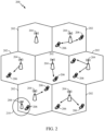
- FIG. 2 is a diagram illustrating an example of an access network 200 in an LTE network architecture.
- the access network 200 is divided into a number of cellular regions (cells) 202.
- One or more lower power class eNBs 208 may have cellular regions 210 that overlap with one or more of the cells 202.
- a lower power class eNB 208 may be referred to as a remote radio head (RRH).
- the lower power class eNB 208 may be a femto cell (e.g., home eNB (HeNB)), pico cell, or micro cell.
- the macro eNBs 204 are each assigned to a respective cell 202 and are configured to provide an access point to the EPC 110 for all the UEs 206 in the cells 202.
- the eNBs 204 are responsible for all radio related functions including radio bearer control, admission control, mobility control, scheduling, security, and connectivity to the serving gateway 116.
- the network 200 may also include one or more relays (not shown). According to one application, an UE may serve as a relay.
- the modulation and multiple access scheme employed by the access network 200 may vary depending on the particular telecommunications standard being deployed.
- OFDM is used on the DL
- SC-FDMA is used on the UL to support both frequency division duplexing (FDD) and time division duplexing (TDD).
- FDD frequency division duplexing
- TDD time division duplexing
- FDD frequency division duplexing
- TDD time division duplexing
- EV-DO Evolution-Data Optimized
- UMB Ultra Mobile Broadband
- EV-DO and UMB are air interface standards promulgated by the 3rd Generation Partnership Project 2 (3GPP2) as part of the CDMA2000 family of standards and employs CDMA to provide broadband Internet access to mobile stations. These concepts may also be extended to Universal Terrestrial Radio Access (UTRA) employing Wideband-CDMA (W-CDMA) and other variants of CDMA, such as TD-SCDMA; Global System for Mobile Communications (GSM) employing TDMA; and Evolved UTRA (E-UTRA), Ultra Mobile Broadband (UMB), IEEE 802.11 (Wi-Fi), IEEE 802.16 (WiMAX), IEEE 802.20, and Flash-OFDM employing OFDMA.
- UTRA Universal Terrestrial Radio Access
- W-CDMA Wideband-CDMA
- GSM Global System for Mobile Communications
- E-UTRA Evolved UTRA
- UMB Ultra Mobile Broadband
- IEEE 802.11 Wi-Fi
- WiMAX IEEE 802.16
- IEEE 802.20 Flash-OFDM employing OF
- UTRA, E-UTRA, UMTS, LTE and GSM are described in documents from the 3GPP organization.
- CDMA2000 and UMB are described in documents from the 3GPP2 organization.
- the actual wireless communication standard and the multiple access technology employed will depend on the specific application and the overall design constraints imposed on the system.
- the eNBs 204 may have multiple antennas supporting MIMO technology.
- MIMO technology enables the eNBs 204 to exploit the spatial domain to support spatial multiplexing, beamforming, and transmit diversity.
- Spatial multiplexing may be used to transmit different streams of data simultaneously on the same frequency.
- the data streams may be transmitted to a single UE 206 to increase the data rate or to multiple UEs 206 to increase the overall system capacity. This is achieved by spatially precoding each data stream (e.g., applying a scaling of an amplitude and a phase) and then transmitting each spatially precoded stream through multiple transmit antennas on the DL.
- the spatially precoded data streams arrive at the UE(s) 206 with different spatial signatures, which enables each of the UE(s) 206 to recover the one or more data streams destined for that UE 206.
- each UE 206 transmits a spatially precoded data stream, which enables the eNB 204 to identify the source of each spatially precoded data stream.
- Beamforming may be used to focus the transmission energy in one or more directions. This may be achieved by spatially precoding the data for transmission through multiple antennas. To achieve good coverage at the edges of the cell, a single stream beamforming transmission may be used in combination with transmit diversity.
- OFDM is a spread-spectrum technique that modulates data over a number of subcarriers within an OFDM symbol.
- the subcarriers are spaced apart at precise frequencies. The spacing provides "orthogonality" that enables a receiver to recover the data from the subcarriers.
- a guard interval e.g., cyclic prefix
- the UL may use SC-FDMA in the form of a DFT-spread OFDM signal to compensate for high peak-to-average power ratio (PAPR).
- PAPR peak-to-average power ratio
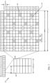
- FIG. 3 is a diagram 300 illustrating an example of a DL frame structure in LTE.
- a frame (10 ms) may be divided into 10 equally sized sub-frames with indices of 0 through 9. Each sub-frame may include two consecutive time slots.
- a resource grid may be used to represent two time slots, each time slot including a resource block.
- the resource grid is divided into multiple resource elements.
- a resource block contains 12 consecutive subcarriers in the frequency domain and, for a normal cyclic prefix in each OFDM symbol, 7 consecutive OFDM symbols in the time domain, or 84 resource elements.
- For an extended cyclic prefix a resource block contains 6 consecutive OFDM symbols in the time domain and has 72 resource elements.
- R 302, R 304 include DL reference signals (DL-RS).
- the DL-RS include Cell-specific RS (CRS) (also sometimes called common RS) 302 and UE-specific RS (UE-RS) 304.
- CRS Cell-specific RS
- UE-RS 304 are transmitted only on the resource blocks upon which the corresponding physical DL shared channel (PDSCH) is mapped.
- PDSCH physical DL shared channel
- the number of bits carried by each resource element depends on the modulation scheme. Thus, the more resource blocks that a UE receives and the higher the modulation scheme, the higher the data rate for the UE.
- an eNB may send a primary synchronization signal (PSS) and a secondary synchronization signal (SSS) for each cell in the eNB.
- the primary and secondary synchronization signals may be sent in symbol periods 6 and 5, respectively, in each of subframes 0 and 5 of each radio frame with the normal cyclic prefix (CP).
- the synchronization signals may be used by UEs for cell detection and acquisition.
- the eNB may send a Physical Broadcast Channel (PBCH) in symbol periods 0 to 3 in slot 1 of subframe 0.
- PBCH Physical Broadcast Channel
- the eNB may send a Physical Control Format Indicator Channel (PCFICH) in the first symbol period of each subframe.
- the PCFICH may convey the number of symbol periods (M) used for control channels, where M may be equal to 1, 2 or 3 and may change from subframe to subframe. M may also be equal to 4 for a small system bandwidth, e.g., with less than 10 resource blocks.
- the eNB may send a Physical HARQ Indicator Channel (PHICH) and a Physical Downlink Control Channel (PDCCH) in the first M symbol periods of each subframe.
- the PHICH may carry information to support hybrid automatic repeat request (HARQ).
- the PDCCH may carry information on resource allocation for UEs and control information for downlink channels.
- the eNB may send a Physical Downlink Shared Channel (PDSCH) in the remaining symbol periods of each subframe.
- the PDSCH may carry data for UEs scheduled for data transmission on the downlink.
- the eNB may send the PSS, SSS, and PBCH in the center 1.08 MHz of the system bandwidth used by the eNB.
- the eNB may send the PCFICH and PHICH across the entire system bandwidth in each symbol period in which these channels are sent.
- the eNB may send the PDCCH to groups of UEs in certain portions of the system bandwidth.
- the eNB may send the PDSCH to specific UEs in specific portions of the system bandwidth.
- the eNB may send the PSS, SSS, PBCH, PCFICH, and PHICH in a broadcast manner to all UEs, may send the PDCCH in a unicast manner to specific UEs, and may also send the PDSCH in a unicast manner to specific UEs.
- Each resource element may cover one subcarrier in one symbol period and may be used to send one modulation symbol, which may be a real or complex value.
- Resource elements not used for a reference signal in each symbol period may be arranged into resource element groups (REGs).
- Each REG may include four resource elements in one symbol period.
- the PCFICH may occupy four REGs, which may be spaced approximately equally across frequency, in symbol period 0.
- the PHICH may occupy three REGs, which may be spread across frequency, in one or more configurable symbol periods. For example, the three REGs for the PHICH may all belong in symbol period 0 or may be spread in symbol periods 0, 1, and 2.
- the PDCCH may occupy 9, 18, 36, or 72 REGs, which may be selected from the available REGs, in the first M symbol periods, for example. Only certain combinations of REGs may be allowed for the PDCCH.
- a subframe may include more than one PDCCH.
- a UE may know the specific REGs used for the PHICH and the PCFICH.
- the UE may search different combinations of REGs for the PDCCH.
- the number of combinations to search is typically less than the number of allowed combinations for the PDCCH.
- An eNB may send the PDCCH to the UE in any of the combinations that the UE will search.
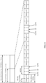
- FIG. 4 is a diagram 400 illustrating an example of an UL frame structure in LTE.
- the available resource blocks for the UL may be partitioned into a data section and a control section.
- the control section may be formed at the two edges of the system bandwidth and may have a configurable size.
- the resource blocks in the control section may be assigned to UEs for transmission of control information.
- the data section may include all resource blocks not included in the control section.
- the UL frame structure results in the data section including contiguous subcarriers, which may allow a single UE to be assigned all of the contiguous subcarriers in the data section.
- a UE may be assigned resource blocks 410a, 410b in the control section to transmit control information to an eNB.
- the UE may also be assigned resource blocks 420a, 420b in the data section to transmit data to the eNB.
- the UE may transmit control information in a physical UL control channel (PUCCH) on the assigned resource blocks in the control section.
- the UE may transmit only data or both data and control information in a physical UL shared channel (PUSCH) on the assigned resource blocks in the data section.
- a UL transmission may span both slots of a subframe and may hop across frequency.
- a set of resource blocks may be used to perform initial system access and achieve UL synchronization in a physical random access channel (PRACH) 430.
- the PRACH 430 carries a random sequence and cannot carry any UL data/signaling.
- Each random access preamble occupies a bandwidth corresponding to six consecutive resource blocks.
- the starting frequency is specified by the network. That is, the transmission of the random access preamble is restricted to certain time and frequency resources. There is no frequency hopping for the PRACH.
- the PRACH attempt is carried in a single subframe (1 ms) or in a sequence of few contiguous subframes and a UE can make only a single PRACH attempt per frame (10 ms).
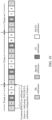
- FIG. 5 is a diagram 500 illustrating an example of a radio protocol architecture for the user and control planes in LTE.
- the radio protocol architecture for the UE and the eNB is shown with three layers: Layer 1, Layer 2, and Layer 3.
- Layer 1 (L1 layer) is the lowest layer and implements various physical layer signal processing functions.
- the L1 layer will be referred to herein as the physical layer 506.
- Layer 2 (L2 layer) 508 is above the physical layer 506 and is responsible for the link between the UE and eNB over the physical layer 506.
- the L2 layer 508 includes a media access control (MAC) sublayer 510, a radio link control (RLC) sublayer 512, and a packet data convergence protocol (PDCP) 514 sublayer, which are terminated at the eNB on the network side.
- MAC media access control
- RLC radio link control
- PDCP packet data convergence protocol
- the UE may have several upper layers above the L2 layer 508 including a network layer (e.g., IP layer) that is terminated at the PDN gateway 118 on the network side, and an application layer that is terminated at the other end of the connection (e.g., far end UE, server, etc.).
- IP layer e.g., IP layer
- the PDCP sublayer 514 provides multiplexing between different radio bearers and logical channels.
- the PDCP sublayer 514 also provides header compression for upper layer data packets to reduce radio transmission overhead, security by ciphering the data packets, and handover support for UEs between eNBs.
- the RLC sublayer 512 provides segmentation and reassembly of upper layer data packets, retransmission of lost data packets, and reordering of data packets to compensate for out-of-order reception due to hybrid automatic repeat request (HARQ).
- HARQ hybrid automatic repeat request
- the MAC sublayer 510 provides multiplexing between logical and transport channels.
- the MAC sublayer 510 is also responsible for allocating the various radio resources (e.g., resource blocks) in one cell among the UEs.
- the MAC sublayer 510 is also responsible for HARQ operations.
- the radio protocol architecture for the UE and eNB is substantially the same for the physical layer 506 and the L2 layer 508 with the exception that there is no header compression function for the control plane.
- the control plane also includes a radio resource control (RRC) sublayer 516 in Layer 3 (L3 layer).
- RRC sublayer 516 is responsible for obtaining radio resources (i.e., radio bearers) and for configuring the lower layers using RRC signaling between the eNB and the UE.
- FIG. 6 is a block diagram of an eNB 610 in communication with a UE 650 in an access network.
- upper layer packets from the core network are provided to a controller/processor 675.
- the controller/processor 675 implements the functionality of the L2 layer.
- the controller/processor 675 provides header compression, ciphering, packet segmentation and reordering, multiplexing between logical and transport channels, and radio resource allocations to the UE 650 based on various priority metrics.
- the controller/processor 675 is also responsible for HARQ operations, retransmission of lost packets, and signaling to the UE 650.
- the TX processor 616 implements various signal processing functions for the L1 layer (i.e., physical layer).
- the signal processing functions includes coding and interleaving to facilitate forward error correction (FEC) at the UE 650 and mapping to signal constellations based on various modulation schemes (e.g., binary phase-shift keying (BPSK), quadrature phase-shift keying (QPSK), M-phase-shift keying (M-PSK), M-quadrature amplitude modulation (M-QAM)).
- FEC forward error correction
- BPSK binary phase-shift keying
- QPSK quadrature phase-shift keying
- M-PSK M-phase-shift keying
- M-QAM M-quadrature amplitude modulation
- Each stream is then mapped to an OFDM subcarrier, multiplexed with a reference signal (e.g., pilot) in the time and/or frequency domain, and then combined together using an Inverse Fast Fourier Transform (IFFT) to produce a physical channel carrying a time domain OFDM symbol stream.
- the OFDM stream is spatially precoded to produce multiple spatial streams.
- Channel estimates from a channel estimator 674 may be used to determine the coding and modulation scheme, as well as for spatial processing.
- the channel estimate may be derived from a reference signal and/or channel condition feedback transmitted by the UE 650.
- Each spatial stream is then provided to a different antenna 620 via a separate transmitter 618TX.
- Each transmitter 618TX modulates an RF carrier with a respective spatial stream for transmission.
- each receiver 654RX receives a signal through its respective antenna 652. Each receiver 654RX recovers information modulated onto an RF carrier and provides the information to the receiver (RX) processor 656.
- the RX processor 656 implements various signal processing functions of the L1 layer.
- the RX processor 656 performs spatial processing on the information to recover any spatial streams destined for the UE 650. If multiple spatial streams are destined for the UE 650, they may be combined by the RX processor 656 into a single OFDM symbol stream.
- the RX processor 656 then converts the OFDM symbol stream from the time-domain to the frequency domain using a Fast Fourier Transform (FFT).
- FFT Fast Fourier Transform
- the symbols on each subcarrier, and the reference signal, is recovered and demodulated by determining the most likely signal constellation points transmitted by the eNB 610. These soft decisions may be based on channel estimates computed by the channel estimator 658. The soft decisions are then decoded and deinterleaved to recover the data and control signals that were originally transmitted by the eNB 610 on the physical channel. The data and control signals are then provided to the controller/processor 659.
- the controller/processor 659 implements the L2 layer.
- the controller/processor can be associated with a memory 660 that stores program codes and data.
- the memory 660 may be referred to as a computer-readable medium.
- the control/processor 659 provides demultiplexing between transport and logical channels, packet reassembly, deciphering, header decompression, control signal processing to recover upper layer packets from the core network.
- the upper layer packets are then provided to a data sink 662, which represents all the protocol layers above the L2 layer.
- Various control signals may also be provided to the data sink 662 for L3 processing.
- the controller/processor 659 is also responsible for error detection using an acknowledgement (ACK) and/or negative acknowledgement (NACK) protocol to support HARQ operations.
- ACK acknowledgement
- NACK negative acknowledgement
- a data source 667 is used to provide upper layer packets to the controller/processor 659.
- the data source 667 represents all protocol layers above the L2 layer.
- the controller/processor 659 implements the L2 layer for the user plane and the control plane by providing header compression, ciphering, packet segmentation and reordering, and multiplexing between logical and transport channels based on radio resource allocations by the eNB 610.
- the controller/processor 659 is also responsible for HARQ operations, retransmission of lost packets, and signaling to the eNB 610.
- Channel estimates derived by a channel estimator 658 from a reference signal or feedback transmitted by the eNB 610 may be used by the TX processor 668 to select the appropriate coding and modulation schemes, and to facilitate spatial processing.
- the spatial streams generated by the TX processor 668 are provided to different antenna 652 via separate transmitters 654TX. Each transmitter 654TX modulates an RF carrier with a respective spatial stream for transmission.
- the UL transmission is processed at the eNB 610 in a manner similar to that described in connection with the receiver function at the UE 650.
- Each receiver 618RX receives a signal through its respective antenna 620.
- Each receiver 618RX recovers information modulated onto an RF carrier and provides the information to a RX processor 670.
- the RX processor 670 may implement the L1 layer.
- the controller/processor 675 implements the L2 layer.
- the controller/processor 675 can be associated with a memory 676 that stores program codes and data.
- the memory 676 may be referred to as a computer-readable medium.
- the control/processor 675 provides demultiplexing between transport and logical channels, packet reassembly, deciphering, header decompression, control signal processing to recover upper layer packets from the UE 650.
- Upper layer packets from the controller/processor 675 may be provided to the core network.
- the controller/processor 675 is also responsible for error detection using an ACK and/or NACK protocol to support HARQ operations.
- the controllers/processors 675, 659 may direct the operation at the eNB 610 and the UE 650, respectively.
- the controller/processor 659 and/or other processors and modules at the UE 650 may perform or direct operations for example operations 1300 in FIG. 13 , and/or other processes for the techniques described herein, for example.
- the controller/processor 675 and/or other processors and modules at the eNB 610 may perform or direct operations for example operations 1200 in FIG 12 , and/or other processes for the techniques described herein, for example.
- one or more of any of the components shown in FIG. 6 may be employed to perform example operations 1200 and 1300 and/or other processes for the techniques described herein.
- Frequency Division Duplex (FDD) and (TDD) frame structures are supported.
- FDD Frequency Division Duplex
- TDD 7 possible DL and UL subframe configurations are supported, as shown in FIG. 7 . It may be noted that there are 2 switching periodicities, 5ms and 10ms. For 5ms, there are two special subframes in one frame (10ms) - as illustrated in FIG. 8 . For 10ms, there is one special subframe in one frame.
- the present methods and apparatus may be employed when a larger or smaller number of subframe configurations are supported.
- TDD DL/UL subframe configurations based on the actual traffic needs, also known as evolved interference management for traffic adaptation (eIMTA).
- eIMTA evolved interference management for traffic adaptation
- the subframe configuration may be changed, for example, from config #1 (6 DL : 4 UL) to config #5 (9 DL : 1 UL).
- the adaptation of TDD configuration is expected to be no slower than 640ms.
- the adaptation may be expected to be as fast as 10ms, although this may not be desirable.
- the adaptation may cause overwhelming interference to both downlink and uplink when two or more cells have different downlink and uplink subframes.
- the adaptation may cause some complexity in DL and UL HARQ timing management.
- each of the seven DL/UL subframe configurations has its own DL/UL HARQ timing.
- the DL/UL HARQ timing is optimized for each configuration (e.g., in terms of HARQ operation efficiency). For example, the timing from PDSCH to the corresponding ACK/NAK may be different for different TDD DL/UL subframe configurations (e.g., depending on when the next available uplink subframe occurs for sending the ACK/NAK).
- Dynamical switching among the 7 configurations implies that if current DL/UL HARQ timing is kept, there may be missed ACK/NAK transmission opportunities for some of the DL or UL transmissions.
- DL HARQ operations may be based on DL/UL subframe configuration #5, regardless of the actual DL/UL subframe configuration in use in a frame (or half a frame).
- the DL HARQ timing may be always based on the 9:1 DL/UL subframe configuration.
- UL HARQ operation can be based, for example, on DL/UL subframe configuration #0, regardless of the actual DL/UL subframe configuration in use in a frame (or half a frame). That is, if dynamic DL/UL subframe configuration is enabled, the UL HARQ timing may be always based on the 4:6 DL/UL subframe configuration, as illustrated in FIG. 9 .
- subframes 3/4/5/7/8/9 may either be DL or UL subframes, while subframe 6 may either be DL or special subframe.
- aspects of the present disclosure discuss techniques for dynamic indication of the TDD UL/DL subframe configuration to UEs.
- common PDCCH or ePDCCH enhanced PDCCH capable of being interpreted by a plurality of UEs may be used for indicating the TDD DL/UL configuration to one or more UEs.
- the common PDCCH (or ePDCCH) is typically associated with a common search space that carries the DCIs (Downlink Control Information) that are common for a plurality of UEs.
- each PDCCH carries one DCI and is identified by RNTI (Radio Network Temporary Identifier) implicitly encoded in the CRC attachment of the DCI.
- RNTI Radio Network Temporary Identifier
- dynamic indication of TDD DL/UL subframe configuration is expected for UEs in RRC_CONNECTED state only. Therefore, in certain aspects, dynamic indication via common PDCCH may be enabled via a common RNTI, for example, DTC (Dynamic TDD DL/UL configuration)-RNTI.
- DTC Dynamic TDD DL/UL configuration
- the selection of a 16-bit DTC-RNTI may follow the same rules as C-RNTI (Cell-RNTI) and avoiding RNTIs used by P-RNTI, SI-RNTI, RA-RNTI, TPC RNTI etc.
- a corresponding PDCCH CRC Cyclic Redundancy Check
- the size of the common PDCCH may either match an existing DCI format or may be a new format.
- the size of common PDCCH may be small or similar to that of DCI format 1C.
- the common PDCCH may include 3-bits indicating the configuration, 5 bits reserved, 16-bit CRC, for a total of 24 bits, which is that same size as DCI format 1C under 1.4MHz or 6-RB system bandwidth.
- the size of the common PDCCH may be bandwidth independent.
- DCI format for the common PDCCH will be referred to as DCI format 5.
- aspects of the present disclosure are directed to anchor subframe based design. Referring back to the TDD configurations of FIG. 7 , four of the subframes are aligned among all subframes (i.e., subframes 0, 1, 2 and 5). In addition, in subframe 6, the downlink transmissions are partially aligned.
- the subframes that align i.e., the subframes that do not change across configurations
- anchor subframes may include subframes 0, 1, 2 and 5.
- subframe 6 may be considered an anchor subframe because the downlink transmissions are partially aligned.
- the subframes that do not align i.e., the subframes that change across different configurations may be referred to as non-anchor subframes.
- the adaptive TDD configurations may be improved based on the anchor subframes.
- the common PDCCH may only be carried in DL anchor subframes, but may not have to be carried in all DL anchor subframes.
- the common PDCCH indicating a TDD DL/UL subframe configuration may be transmitted in early subframes of a frame, or even earlier, for example in a previous frame to allow both eNB and UE to react to the new configuration. For example, to give UE enough time to decode the common PDCCH and determine the TDD UL/DL subframe configuration.
- FIG. 10 illustrates transmission of the common PDCCH in subframe 5 of frame n-1 indicating TDD DL/UL subframe configuration of frame n.
- a set of subframes for UE to monitor DCI format 5 may be pre-determined, or indicated by signaling (e.g., broadcast or unicast). For example, subframe 5 of all frames may be predetermined to carry the common PDCCH.
- one of the SIBs may indicate which subframes/frames carry DCI format 5.
- dedicated signaling may be used to indicate which subframes/frames carry DCI format 5.
- a same subframe configuration indication may be transmitted in multiple subframes. UEs may monitor the multiple subframes for the same TDD DL/UL subframe configuration indication, in order to facilitate eNB control load balancing and Discontinuous Reception (DRX) operation for the UEs. For example, UEs may monitor the common PDCCH in both subframes 5 and 6.
- DRX Discontinuous Reception
- different UEs may have different DRX operation.
- a UE1 may monitor subframe 5 and another UE2 may monitor 6 due to the DRX operation being subframe specific. Therefore, in an aspect, the set of subframes for a UE to monitor DCI format 5 may be tied with its DRX operation. This, for example, may ensure that there is at least one subframe carrying DCI format 5 in certain duration.
- a UE may need to pre-wake-up to monitor DCI format 5 before ON duration, especially during long DRX.
- a UE if a UE cannot detect the common PDCCH, it may fall back to a legacy or reference configuration.
- the eNB may consider transmitting the common PDCCH in at least two DL anchor subframes to increase reliability. From UE perspective, it may monitor the common PDCCH in at least two DL subframes and may also combine the two DL subframes for joint decoding (TTI bundling for PDCCH) for more time diversity. For example, compared with one level 4 PDCCH transmission in one subframe, there may be 2 level 2 PDCCH transmissions in two subframes.
- reliability of the common PDCCH may further be increased by power control.
- the sets of usable subframes there may be restriction on the sets of usable subframes. For example, some subframes may experience interference on UL or DL and thus an eNB may use only certain subframes (e.g., subframes when interfering cell(s) is configured with almost blank subframes). As a result, the set of subframes for use may be restricted.
- the time location of the common PDCCH may be different for different cells. For example, as shown in FIG. 11 , cell 1 uses subframe 5 while cell 2 uses subframe 6 for transmitting the common PDCCH.
- the UE may not be required to decode DCI format 1C.
- the set of decoding candidates originally monitored for DCI format 1C may be used for DCI format 5, thus maintaining the same number of blind decodes as DCI format 5.
- the new DCI format may replace DCI format 1C for UEs to monitor certain subframes. As a result, there is no increase of the number of DCI sizes to monitor.
- the number of decoding candidates for DCI format 5 should be the same as DCI format 1C.
- the set of aggregation levels for DCI format 5 may be may be revised to be different from that of DCI format 1C (which typically has 4 decoding candidates for level 4, and 2 decoding candidates for level 8 - total of 6 decoding candidates) in order to accommodate DCI format 5.
- An example set of aggregation levels are ⁇ 1, 2, 2, 1 ⁇ for aggregation levels ⁇ 1, 2, 4, 8 ⁇ , respectively. i.e. we can still support original aggregation levels ⁇ 1, 2, 4, 8 ⁇ for DCI format 5, but in order to maintain same decoding candidates aggregation levels ⁇ 1, 2, 2, 1 ⁇ may be used for aggregation levels ⁇ 1, 2, 4, 8 ⁇ .
- the common search space always starts from CCE 0.
- the common search space may also start with CCE 0. But this may be restrictive as it may collide with common search space transmissions. That is, for DCI format 5 the starting CCE of each aggregation level may be the same common search space for the same aggregation levels and within the common search space for other new aggregation levels, but restrictive given that it may collide with common search space related operations (e.g., paging, RAR response, system information broadcast, etc.). As a result, two alternatives may be designed to address this concern.
- starting CCE may be configured via RRC signaling.
- the RRC configuration may be aggregation level dependent and/or subframe dependent. It may be common to all UEs of a cell, or common to a group of UEs of a cell, but different for different groups (two or more groups) of UEs of the cell.
- the starting CCE may be derived based on DTC-RNTI, similar to C-RNTI. This approach is simple and at the same time effective. Further simplification may be possible, e.g., the starting CCE for all aggregation levels may be the same (e.g., based on level 8).
- dynamic indication of the TDD UL/DL subframe configuration may be supported via ePDCCH.
- the discussions earlier for the common PDCCH may be largely applied for ePDCCH, but with some differences.
- distributed ePDCCH may preferably be used for the common EPDCCH DCI format 5.
- it is sufficient that the common EPDCCH is located in one resource set, if the UE is configured with two ePDCCH resource sets.
- dynamic indication may be conveyed via some localized ePDCCH.
- the UE may monitor only one of common PDCCH or common ePDCCH for dynamic indication of TDD subframe configuration.
- the UE may monitor both common PDCCH or common ePDCCH for dynamic indication of TDD subframe configuration if the UE is configured to monitor PDCCH and ePDCCH over different subframes.
- DCI format 5 replaces DCI format 1C
- UEs may be allowed to monitor both DCI format 5 and DCI format 1C in the same subframe.
- the size of DCI format 5 may be the same or different from that of DCI format 1C. In the case of same size, some bit(s) inside the payload may be used to differentiate 1C from 5.
- the sizes of the formats 5 and 1C are different, in order to maintain the same number of blind decodes (or to minimize the total number of blind decodes), splitting the decoding candidates may be considered between 1C and 5 in one subframe for the UE to monitor. For example, 3 decoding candidates for 5 (2 level 2 and 1 level 4), and 3 decoding candidates for DCI format 1C (2 level 4 and 1 level 8). In an aspect, there may also be an uneven split of decoding candidates between the two formats.
- a macro cell and its associated small cells may have the same PCI.
- search space for DCI format 5 may collide.
- differentiation of DCI format 5 for macro cell and its associated small cells of the same PCI should be supported. In an aspect, this may be accomplished by non-overlapping DCI format 5 search spaces for macro and small cells, e.g., by configuring different starting CCEs or ECCEs.
- same search space may be used, but within each DCI format, an index may be included identifying a small cell within the same cluster of the same PCI (e.g., similar to DCI 3/3A based group power control, where each TPC_index corresponds to a particular UE).
- UEs may be further indicated the mapping between the indices and the small cells.
- DTC-RNTI may be configured differently for different small cells of the same PCI. That is, for a same PCI, UEs may be required to monitor two or more DTC-RNTIs.
- the corresponding search spaces for the two or more DTC-RNTIs may be the same or separately defined (e.g., based on each individual DTC-RNTI).
- the common PDCCH or the common ePDCCH may further carry an information field identifying one or more frames that a TDD DL/UL subframe configuration should be applied.
- the information field may be a 2-bit information field, and indicates the TDD DL/UL subframe configuration should be applied to one of the current frame (N), the next frame (N+1), frame N+2, or frame N+3, where the current frame N is the frame where the common PDCCH or the common ePDCCH is transmitted.
- the common PDCCH or the common ePDCCH may further carry an information field identifying a duration that a TDD DL/UL subframe configuration should be applied.
- the information field may be a 2-bit information field, and indicates the TDD DL/UL subframe configuration should be applied to one of 1, 2, 4 or 8 frames starting from the current frame (N), where the current frame N is the frame where the common PDCCH or the common ePDCCH is transmitted.
- the applicability of a TDD DL/UL subframe configuration conveyed in a common PDCCH or a common ePDCCH depends on the subframe indices in a frame where the PDCCH or the ePDCCH is transmitted. As an example, if the PDCCH or ePDCCH is transmitted in the first half of a frame (i.e., subframes 0 to 4), the TDD DL/UL subframe configuration in the control channel is applicable to the current frame; if the PDCCH or ePDCCH is transmitted in the second half of a frame (i.e., subframes 5 to 9), the TDD DL/UL subframe configuration in the control channel is applicable to the next frame.
- FIG. 12 illustrates example operations 1200 performed, for example, by a base station (BS) for dynamic indication of TDD UL/DL subframe configuration, in accordance with aspect of the disclosure.
- Operations 1200 begin, at 1202, by identifying one or more anchor subframes and one or more non-anchor subframes in a frame.
- the BS dynamically changes an uplink/downlink configuration of the frame used for communicating with a plurality of UEs.
- the BS signals the changed configuration using a common downlink control channel capable of being interpreted by the plurality of UEs in at least one of the one or more anchor subframes of the frame.
- size of the common downlink control channel may be same as the size defined for a legacy LTE DCI format.
- the legacy LTE DCI format may include DCI format 1C.
- the size of the common downlink control channel may be independent of a downlink system bandwidth.
- the base station may scramble CRC code of the common downlink control channel by RNTI specific to the common downlink control channel.
- the base station may configure two or more RNTI values for cells of a same physical cell identity (PCI), wherein each of the plurality of UEs is indicated to monitor only one of the two or more RNTI values.
- PCI physical cell identity
- the signaling of the changed configuration may include transmitting the common downlink control channel only in a subset of the one or more anchor subframes of the frame.
- the signaling of the changed configuration may include comprises transmitting the common downlink control channel in the one or more anchor subframes of the frame for indicating the uplink/downlink configuration for another subsequent frame.
- the base station may indicate to at least one UE of the plurality of UEs via explicit signaling a set of subframes configured to carry the common downlink control channel.
- the explicit signaling may include signaling via a System Information Block (SIB).
- SIB System Information Block
- the explicit signaling may include dedicated signaling for the indication.
- a set of subframes configured to carry the common downlink control channel may be pre-determined.
- the base station my determine a set of subframes to carry the common downlink control channel for each UE based on a DRX operation of the UE such that at least one subframe carries the downlink control channel in a DRX ON duration.
- the signaling of the changed configuration may include transmitting the common downlink control channel in at least two downlink anchor subframes.
- the time location of a subframe carrying the common downlink control channel may be different for different cells.
- the signaling of the changed configuration may include transmitting the common downlink control channel in a subframe originally configured for transmission of a legacy downlink control channel such that a number of decoding candidates for blind decoding the common downlink control channel is same as a number of decoding candidates for blind decoding the legacy downlink control channel.
- transmission of the common downlink control channel may replace the transmission of the legacy downlink control channel in the subframe.
- starting CCEs of search spaces for blind decoding of the common downlink control channel and the legacy downlink control channel may be the same.
- the starting CCE of a search space for blind decoding of the common downlink control channel may be configured via Radio Resource Control (RRC) signaling.
- RRC Radio Resource Control
- the RRC signaling is UE-specific.
- the starting CCE of a search space for blind decoding of the common downlink control channel may be derived based on a Radio Network Temporary Identifier (RNTI) specific to the common downlink control channel.
- RNTI Radio Network Temporary Identifier
- the base station may further transmit the common downlink control channel and the legacy downlink control channel simultaneously in the subframe.
- the sizes of the common downlink control channel and the legacy downlink control channel may be the same.
- the base station may transmit a bit to differentiate between the common downlink control channel and the legacy downlink control channel.
- the uplink/downlink configuration of the subframes may include a Time Division Duplex (TDD) Uplink-Downlink configuration.
- the common downlink control channel may include PDCCH or ePDCCH.
- a search space for blind decoding of the common downlink control channel may include candidates of at least one of aggregation level 1, aggregation level 2, aggregation level 4, or aggregation level 8.
- the common downlink control channel may include information about one or more frames to which the changed configuration is to be applied.
- the common downlink control channel may include an information field to carry the information about the one or more frames.
- the common downlink control channel may include information about a duration for which the changed configuration is to be applied.
- the duration may include one or more frame lengths.
- the information may include a start frame number of a frame starting from which the changed configuration is to be applied for the duration.
- application of the changed configuration to one or more frames is a function of a location of transmission of the common downlink control channel within the frame. If the common downlink control channel is transmitted in a first portion of the frame, the changed configuration is applied to the frame. If the common downlink control channel is transmitted in a second portion of the frame, the changed configuration is applied to a subsequent frame.
- the first and second portions of the frame may include the first and second halves of the frame respectively.
- FIG. 13 illustrates example operations 1300 performed, for example, by a user equipment (UE) for dynamic indication of TDD UL/DL subframe configuration, in accordance with aspect of the disclosure.
- Operations 1300 may begin, at 1302, by monitoring one or more anchor subframes of a frame for a common downlink control channel indicating a changed uplink/downlink configuration of subframes used for communication with at least the UE.
- the UE may decode the common downlink control channel to determine the changed uplink/downlink configuration of subframes for use in subsequent communication.
- the size of the common downlink control channel is same as the size defined for a legacy LTE DCI format. In certain aspects, the size of the common downlink control channel may be independent of a downlink system bandwidth. In an aspect, the legacy LTE DCI format may include DCI format 1C.
- the CRC code of the common downlink control channel may be scrambled by RNTI specific to the common downlink control channel.
- two or more RNTI values may be configured for cells of a same physical cell identity (PCI), wherein the UE monitors only one of the two or more RNTI values.
- PCI physical cell identity
- the indication of the changed configuration may include the common downlink control channel only in a subset of the one or more anchor subframes of the frame.
- the indication of the changed configuration may include the common downlink control channel in the one or more anchor subframes of the frame indicating the uplink/downlink configuration for another subsequent frame
- the UE may receive indication via explicit signaling of a set of subframes configured to carry the common downlink control channel.
- the explicit signaling may include signaling via a SIB.
- the explicit signaling may include dedicated signaling for the indication.
- a set of subframes configured to carry the common downlink control channel may be pre-determined.
- a set of subframes carrying the common downlink control channel for each UE is based on a DRX operation of the UE such that at least one subframe carries the downlink control channel in a DRX ON duration.
- the indication of the changed configuration may include the common downlink control channel in at least two downlink anchor subframes.
- the time location of a subframe carrying the common downlink control channel may be different for different cells.
- the UE determines one or more frames to apply the changed configuration as a function of a location of transmission of the common control channel within the frame. If the common downlink control channel is transmitted in a first portion of the frame, the changed configuration is applied to the frame itself. If the common downlink control channel is transmitted in a second different portion of the frame, the changed configuration is applied to a subsequent frame.
- the first and second portions of the frame may include first and second halves of the frame respectively.
- the UE may determine a duration for which the changed configuration is to be applied based on information transmitted in the common downlink control channel.
- the indication of the changed uplink/downlink configuration may include the common downlink control channel in a subframe originally configured for transmission of a legacy downlink control channel such that a number of decoding candidates for blind decoding the common downlink control channel is same as a number of decoding candidates for blind decoding the legacy downlink control channel.
- the common downlink control channel may replace the legacy downlink control channel in the subframes.
- starting CCEs of search spaces for blind decoding of the common downlink control channel and the legacy downlink control channel may be the same.
- the starting CCE of a search space for blind decoding of the common downlink control channel was configured via Radio Resource Control (RRC) signaling.
- RRC Radio Resource Control
- the RRC signaling may be UE-specific.
- the starting CCE of a search space for blind decoding of the common downlink control channel was derived based on a Radio Network Temporary Identifier (RNTI) specific to the common downlink control channel.
- RNTI Radio Network Temporary Identifier
- the common downlink control channel and the legacy downlink control channel may be received simultaneously in the subframe.
- the sizes of the common downlink control channel and the legacy downlink control channel may be the same.
- the indication of the configuration may include a bit to differentiate between the common downlink control channel and the legacy downlink control channel.
- the uplink/downlink configuration of the subframes is include a Time Division Duplex (TDD) Uplink-Downlink configuration.
- TDD Time Division Duplex
- the common downlink control channel comprises PDCCH or ePDCCH.
- a search space for blind decoding of the common downlink control channel may include candidates of at least one of aggregation level 1, aggregation level 2, aggregation level 4, or aggregation level 8
- a phrase referring to "at least one of" a list of items refers to any combination of those items, including single members.
- "at least one of: a , b , or c” is intended to cover: a, b, c, a-b, a-c, b-c, and a-b-c .
Landscapes
- Engineering & Computer Science (AREA)
- Signal Processing (AREA)
- Computer Networks & Wireless Communication (AREA)
- Mobile Radio Communication Systems (AREA)
- Bidirectional Digital Transmission (AREA)
- Time-Division Multiplex Systems (AREA)
Claims (15)
- Un procédé (1200) de communication sans fil réalisé par une station de base, BS, (106, 108, 204), comprenant :l'identification (1202) d'une ou plusieurs sous-trames d'ancrage et d'une ou plusieurs sous-trames non d'ancrage dans une trame, dans lequel les sous-trames d'ancrage sont des sous-trames qui ne changent pas entre configurations de duplexage par répartition dans le temps, TDD ;la modification dynamique (1204) d'une configuration de liaison montante/liaison descendante TDD de la trame utilisée pour communiquer avec une pluralité d'équipements utilisateurs, UE, (102) ; etla signalisation (1206) de la configuration modifiée en utilisant un canal commun de contrôle de liaison descendante apte à être interprété par la pluralité d'UE (102) dans au moins une des une ou plusieurs sous-trames d'ancrage de la trame, caractérisé par le fait que :
si le canal commun de contrôle de liaison descendante est transmis dans une première partie de la trame, la configuration modifiée est appliquée à la trame et, si le canal commun de contrôle de liaison descendante est transmis dans une seconde partie de la trame, la configuration modifiée est appliquée à une trame ultérieure. - Le procédé (1200) selon la revendication 1, dans lequel une taille du canal commun de contrôle de liaison descendante est la même qu'une taille définie pour un format d'information de contrôle de liaison descendante, DCI, Évolution à long terme, LTE, héritée.
- Le procédé (1200) selon la revendication 1, comprenant en outre le brouillage d'un code de contrôle de redondance cyclique, CRC, du canal commun de contrôle de liaison descendante par un identifiant temporaire de réseau radio, RNTI, spécifique au canal commun de contrôle de liaison descendante.
- Le procédé (1200) selon la revendication 1, comprenant en outre la configuration d'au moins deux valeurs de RNTI pour des cellules de même identité de cellule physique, PCI, dans lequel chacun de la pluralité d'UE (102) est indiqué pour surveiller seulement une des au moins deux valeurs de RNTI.
- Le procédé (1200) selon la revendication 1, dans lequel la signalisation (1206) comprend la transmission du canal commun de contrôle de liaison descendante dans les une ou plusieurs sous-trames d'ancrage de la trame pour l'indication de la configuration de liaison montante/liaison descendante TDD pour une autre trame ultérieure.
- Le procédé (1200) selon la revendication 1, comprenant en outre l'indication à au moins un UE (102) de la pluralité d'UE (102) via une signalisation explicite d'un ensemble de sous-trames configurées pour porter le canal commun de contrôle de liaison descendante.
- Le procédé (1200) selon la revendication 1, comprenant en outre la détermination d'un ensemble de sous-trames pour porter le canal commun de contrôle de liaison descendante pour chaque UE (102) sur la base d'une opération de réception discontinue, DRX, de l'UE (102) de manière qu'au moins une sous-trame porte le canal de contrôle de liaison descendante sur une durée DRX ON.
- Un procédé (1300) de communication sans fil réalisé par un équipement utilisateur, UE, (102), comprenant :la surveillance (1302) d'une ou plusieurs sous-trames d'ancrage d'une trame pour un canal commun de contrôle de liaison descendante indiquant une configuration modifiée de liaison montante/liaison descendante de duplexage par répartition dans le temps, TDD de sous-trames utilisées pour une communication avec au moins l'UE (102), dans lequel les sous-trames d'ancrage sont des sous-trames qui ne changent pas entre configurations TDD ;le décodage (1304) du canal commun de contrôle de liaison descendante pour déterminer la configuration modifiée de liaison montante/liaison descendante TDD de sous-trames pour l'utilisation dans une communication ultérieure ;caractérisé par le fait que :
si le canal commun de contrôle de liaison descendante est transmis dans une première partie de la trame, la configuration modifiée est appliquée à la trame et, si le canal commun de contrôle de liaison descendante est transmis dans une seconde partie de la trame, la configuration modifiée est appliquée à une trame ultérieure. - Le procédé (1300) selon la revendication 8, dans lequel une taille du canal commun de contrôle de liaison descendante est la même qu'une taille définie pour un format d'information de contrôle de liaison descendante, DCI, Évolution à long terme, LTE, héritée ; ou
dans lequel le code de contrôle de redondance cyclique, CRC, du canal commun de contrôle de liaison descendante est brouillé par un identifiant temporaire de réseau radio, RNTI, spécifique au canal commun de contrôle de liaison descendante. - Le procédé (1300) selon la revendication 8, dans lequel l'indication de la configuration modifiée de liaison montante/liaison descendante TDD comprend le canal commun de contrôle de liaison descendante dans les une ou plusieurs sous-trames d'ancrage de la trame indiquant la configuration de liaison montante/liaison descendante TDD pour une autre trame ultérieure.
- Le procédé (1300) selon la revendication 8, comprenant en outre la réception d'une indication via une signalisation explicite d'un ensemble de sous-trames configurées pour porter le canal commun de contrôle de liaison descendante.
- Le procédé (1300) selon la revendication 8, dans lequel un ensemble de sous-trames pour porter le canal commun de contrôle de liaison descendante pour chaque UE (102) est basé sur une opération de réception discontinue, DRX, de l'UE (102) de manière qu'au moins une sous-trame porte le canal de contrôle de liaison descendante sur une durée DRX ON.
- Une station de base, BS, (106, 108, 204), comprenant :un moyen pour identifier une ou plusieurs sous-trames d'ancrage et une ou plusieurs sous-trames non d'ancrage dans une trame, dans laquelle les sous-trames d'ancrage sont des sous-trames qui ne changent pas entre configurations de duplexage par répartition dans le temps, TDD ;un moyen pour modifier de manière dynamique une configuration de liaison montante/liaison descendante TDD de la trame utilisée pour communiquer avec une pluralité d'équipements utilisateurs, UE, (102) ; etun moyen pour signaler la configuration modifiée en utilisant un canal commun de contrôle de liaison descendante apte à être interprété par la pluralité d'UE (102) dans au moins une des une ou plusieurs sous-trames d'ancrage de la trame ; et caractérisé par :
un moyen pour appliquer la configuration modifiée à la trame si le canal commun de contrôle de liaison descendante est transmis dans une première partie de la trame, et pour appliquer la configuration modifiée à une trame ultérieure si le canal commun de contrôle de liaison descendante est transmis dans une seconde partie de la trame. - Un équipement utilisateur, UE, (102), comprenant :un moyen pour surveiller une ou plusieurs sous-trames d'ancrage d'une trame pour un canal commun de contrôle de liaison descendante indiquant une configuration modifiée de liaison montante/liaison descendante de duplexage par répartition dans le temps, TDD de sous-trames utilisées pour une communication avec au moins l'UE (102), dans lequel les sous-trames d'ancrage sont des sous-trames qui ne changent pas entre configurations TDD ;un moyen pour décoder le canal commun de contrôle de liaison descendante pour déterminer la configuration modifiée de liaison montante/liaison descendante TDD de sous-trames pour l'utilisation dans une communication ultérieure ; et caractérisé par :
un moyen pour déterminer d'appliquer la configuration modifiée à la trame si le canal commun de contrôle de liaison descendante est transmis dans une première partie de la trame, et d'appliquer la configuration modifiée à une trame ultérieure si le canal commun de contrôle de liaison descendante est transmis dans une seconde partie de la trame. - Un programme de calculateur comprenant des instructions qui, quand le programme est exécuté par un calculateur, amènent le calculateur à réaliser les étapes de l'une des revendications 1 à 12.
Applications Claiming Priority (3)
| Application Number | Priority Date | Filing Date | Title |
|---|---|---|---|
| PCT/CN2013/080330 WO2015013862A1 (fr) | 2013-07-29 | 2013-07-29 | Indication dynamique de configurations de sous-trames montantes/descendantes en duplexage par répartition dans le temps (tdd) |
| PCT/CN2013/081188 WO2015013993A1 (fr) | 2013-07-29 | 2013-08-09 | Indication dynamique de configurations de sous-trames montantes/descendantes en duplexage par répartition dans le temps (tdd) |
| PCT/CN2014/082118 WO2015014207A1 (fr) | 2013-07-29 | 2014-07-14 | Indication dynamique de configurations de sous-trame de liaison montante/liaison descendante de duplex par répartition dans le temps (tdd) |
Publications (4)
| Publication Number | Publication Date |
|---|---|
| EP3028516A1 EP3028516A1 (fr) | 2016-06-08 |
| EP3028516A4 EP3028516A4 (fr) | 2017-03-29 |
| EP3028516B1 true EP3028516B1 (fr) | 2023-08-16 |
| EP3028516C0 EP3028516C0 (fr) | 2023-08-16 |
Family
ID=52430812
Family Applications (1)
| Application Number | Title | Priority Date | Filing Date |
|---|---|---|---|
| EP14832594.7A Active EP3028516B1 (fr) | 2013-07-29 | 2014-07-14 | Indication dynamique de configurations de sous-trame de liaison montante/liaison descendante de duplex par répartition dans le temps (tdd) |
Country Status (20)
| Country | Link |
|---|---|
| US (1) | US10244518B2 (fr) |
| EP (1) | EP3028516B1 (fr) |
| JP (1) | JP6549117B2 (fr) |
| KR (1) | KR102231185B1 (fr) |
| CN (2) | CN110635888B (fr) |
| AU (2) | AU2014299129A1 (fr) |
| CA (1) | CA2917428C (fr) |
| CL (1) | CL2016000347A1 (fr) |
| ES (1) | ES2953707T3 (fr) |
| HK (1) | HK1222081A1 (fr) |
| IL (1) | IL243158B (fr) |
| MX (1) | MX360406B (fr) |
| MY (1) | MY179622A (fr) |
| PH (1) | PH12016500014A1 (fr) |
| PL (1) | PL3028516T3 (fr) |
| RU (1) | RU2663815C2 (fr) |
| SA (1) | SA516370483B1 (fr) |
| SG (1) | SG11201510320QA (fr) |
| WO (3) | WO2015013862A1 (fr) |
| ZA (1) | ZA201600950B (fr) |
Families Citing this family (31)
| Publication number | Priority date | Publication date | Assignee | Title |
|---|---|---|---|---|
| US20150089382A1 (en) | 2013-09-26 | 2015-03-26 | Wu-chi Feng | Application context migration framework and protocol |
| US20150195056A1 (en) * | 2014-01-06 | 2015-07-09 | Intel IP Corporation | Systems, methods, and devices to support a fast tdd configuration indication |
| US10123323B2 (en) * | 2014-10-24 | 2018-11-06 | Qualcomm Incorporated | Dynamic uplink/downlink frame structure for enhanced component carriers |
| KR101922250B1 (ko) | 2015-07-17 | 2018-11-26 | 주식회사 케이티 | 자원 할당 방법 및 통신 장치 |
| CN107005370B (zh) * | 2015-08-21 | 2019-09-20 | 华为技术有限公司 | 一种数据通信方法及装置 |
| WO2017052326A1 (fr) * | 2015-09-24 | 2017-03-30 | Lg Electronics Inc. | Procédé et appareil de traitement de divers accès de réseau d'ido dans un système de communication sans fil |
| CN107294684B (zh) * | 2016-04-01 | 2021-07-09 | 夏普株式会社 | 配置非锚物理资源块的方法和基站、确定非锚物理资源块位置的方法和用户设备 |
| US10368329B2 (en) * | 2016-04-11 | 2019-07-30 | Qualcomm Incorporated | Synchronization for standalone LTE broadcast |
| US10631331B2 (en) * | 2016-04-22 | 2020-04-21 | Qualcomm Incorporated | Frame structure signaling for multefire |
| CN107465495B (zh) * | 2016-06-03 | 2020-08-28 | 北京佰才邦技术有限公司 | 一种传输状态的指示方法及装置 |
| WO2017213222A1 (fr) * | 2016-06-10 | 2017-12-14 | 株式会社Nttドコモ | Terminal d'utilisateur et procédé de radiocommunication |
| WO2018144642A1 (fr) * | 2017-02-03 | 2018-08-09 | Intel IP Corporation | Structure de trame pour un internet des objets sans licence |
| RU2735954C1 (ru) * | 2017-03-02 | 2020-11-11 | Нтт Докомо, Инк. | Терминал и способ радиосвязи |
| EP4132188A1 (fr) * | 2017-03-07 | 2023-02-08 | Apple Inc. | Surveillance de canaux de commande dans des ensembles de ressources de commande pour une nouvelle radio |
| NZ758247A (en) * | 2017-03-16 | 2022-04-29 | Huawei Tech Co Ltd | Transmission direction configuration method, device, and system |
| EP3606279A4 (fr) * | 2017-04-18 | 2020-04-08 | Huawei Technologies Co., Ltd. | Procédé et dispositif pour indiquer une configuration de sous-trame |
| US10659151B2 (en) | 2017-04-21 | 2020-05-19 | Apple Inc. | Apparatus, system and method for utilizing a flexible slot format indicator |
| US10673605B2 (en) | 2017-06-15 | 2020-06-02 | Apple Inc. | Semi-static and dynamic TDD configuration for 5G-NR |
| WO2019030378A1 (fr) * | 2017-08-11 | 2019-02-14 | Telefonaktiebolaget Lm Ericsson (Publ) | Signalisation de commande commune de fonctionnement efficace de système |
| CN109391422B (zh) | 2017-08-11 | 2020-11-17 | 华为技术有限公司 | 一种反馈码本确定的方法及终端设备、网络设备 |
| JP6758509B2 (ja) * | 2017-10-02 | 2020-09-23 | テレフオンアクチーボラゲット エルエム エリクソン(パブル) | 無線通信用のランダムアクセスチャネルの構成 |
| US10687324B2 (en) | 2017-10-02 | 2020-06-16 | Telefonaktiebolaget Lm Ericsson (Publ) | PDCCH monitoring periodicity |
| EP4351070A3 (fr) | 2017-10-02 | 2024-06-26 | Telefonaktiebolaget LM Ericsson (publ) | Periodicite de surveillance de pdcch |
| US10707915B2 (en) * | 2017-12-04 | 2020-07-07 | Qualcomm Incorporated | Narrowband frequency hopping mechanisms to overcome bandwidth restrictions in the unlicensed frequency spectrum |
| CN109688627B (zh) | 2018-03-29 | 2022-05-10 | 新华三技术有限公司 | 一种无线资源调度方法、网络侧设备及用户设备 |
| EP3813450A4 (fr) * | 2018-07-06 | 2022-01-26 | Beijing Xiaomi Mobile Software Co., Ltd. | Procédé et appareil pour reconnaître une transmission de liaison descendante |
| CN110740025B (zh) * | 2018-07-20 | 2021-03-02 | 维沃移动通信有限公司 | 一种信道检测指示方法、终端及网络设备 |
| US11483814B2 (en) * | 2019-01-04 | 2022-10-25 | Qualcomm Incorporated | Control channel design for shared wireless communications |
| CN113228821B (zh) | 2019-01-11 | 2024-05-24 | 瑞典爱立信有限公司 | 交叉链路干扰管理的节点间协调 |
| WO2022147826A1 (fr) * | 2021-01-11 | 2022-07-14 | Lenovo (Beijing) Limited | Procédé et appareil de transmission en liaison montante |
| WO2023115271A1 (fr) * | 2021-12-20 | 2023-06-29 | 北京小米移动软件有限公司 | Procédés et appareils d'indication et de détermination de transmission de liaison montante, appareil de communication et support de stockage |
Family Cites Families (19)
| Publication number | Priority date | Publication date | Assignee | Title |
|---|---|---|---|---|
| JP4814176B2 (ja) | 2007-05-01 | 2011-11-16 | 株式会社エヌ・ティ・ティ・ドコモ | 基地局装置および同期チャネル送信方法 |
| CA2775371C (fr) * | 2009-09-25 | 2018-03-13 | Research In Motion Limited | Systeme et procede pour l'exploitation d'un reseau a multiples porteuses |
| WO2011064669A2 (fr) * | 2009-11-30 | 2011-06-03 | Pluristem Ltd. | Cellules adhérentes du placenta et leur utilisation dans le traitement de pathologies |
| US9240510B2 (en) * | 2009-12-07 | 2016-01-19 | Electrotherm, Inc. | Concentrated photovoltaic and thermal solar energy collector |
| US20110235599A1 (en) | 2010-03-29 | 2011-09-29 | Samsung Electronics Co., Ltd. | Method and system for uplink acknowledgement signaling in carrier-aggregated wireless communication systems |
| CN102594438B (zh) * | 2011-01-13 | 2017-03-15 | 中兴通讯股份有限公司 | 数据传输方法、装置及系统 |
| WO2012113131A1 (fr) | 2011-02-21 | 2012-08-30 | Renesas Mobile Corporation | Configuration dynamique de liaison montante/descendante pour le duplexage par répartition temporelle |
| WO2012148222A2 (fr) * | 2011-04-27 | 2012-11-01 | Lg Electronics Inc. | Procédé et dispositif de transmission d'informations de contrôle dans un système de communication sans fil |
| KR102031031B1 (ko) * | 2011-06-20 | 2019-10-15 | 삼성전자 주식회사 | 무선 통신 시스템에서 시분할 복식 프레임 구성 정보 송수신 방법 및 장치 |
| US20130027217A1 (en) * | 2011-07-29 | 2013-01-31 | General Electric Company | Systems, Methods, and Apparatus for Automatically Configuring a Utility Meter |
| US8705556B2 (en) * | 2011-08-15 | 2014-04-22 | Blackberry Limited | Notifying a UL/DL configuration in LTE TDD systems |
| US8923274B2 (en) | 2011-08-15 | 2014-12-30 | Blackberry Limited | Notifying a UL/DL configuration in LTE TDD systems |
| US9119120B2 (en) | 2012-01-23 | 2015-08-25 | Intel Corporation | Network assisted user association and offloading techniques for integrated multi-rat heterogeneous networks |
| US9143984B2 (en) | 2012-04-13 | 2015-09-22 | Intel Corporation | Mapping of enhanced physical downlink control channels in a wireless communication network |
| US9642148B2 (en) * | 2012-05-01 | 2017-05-02 | Qualcomm Incorporated | Interference cancellation based on adaptive time division duplexing (TDD) configurations |
| WO2014043863A1 (fr) * | 2012-09-19 | 2014-03-27 | Qualcomm Incorporated | Procédé et appareil pour séparer un groupe de cellules pour mitigation d'interférence eimta lte |
| WO2014049169A1 (fr) | 2012-09-28 | 2014-04-03 | Nokia Siemens Networks Oy | Indication de distribution de temps pour la reconfiguration de liaison montante/descendante (ul/dl) en duplexage par répartition dans le temps (tdd) dynamique |
| US9191930B2 (en) * | 2013-03-13 | 2015-11-17 | Samsung Electronics Co., Ltd. | Transmission of acknowledgement information in adaptively configured TDD communication systems |
| US9474089B2 (en) * | 2013-10-22 | 2016-10-18 | Acer Incorporated | User equipment and base station with configurable carrier |
-
2013
- 2013-07-29 WO PCT/CN2013/080330 patent/WO2015013862A1/fr active Application Filing
- 2013-08-09 WO PCT/CN2013/081188 patent/WO2015013993A1/fr active Application Filing
-
2014
- 2014-07-14 ES ES14832594T patent/ES2953707T3/es active Active
- 2014-07-14 CA CA2917428A patent/CA2917428C/fr active Active
- 2014-07-14 US US14/905,929 patent/US10244518B2/en active Active
- 2014-07-14 RU RU2016102610A patent/RU2663815C2/ru active
- 2014-07-14 WO PCT/CN2014/082118 patent/WO2015014207A1/fr active Application Filing
- 2014-07-14 CN CN201910966550.1A patent/CN110635888B/zh active Active
- 2014-07-14 CN CN201480042170.4A patent/CN105409310B/zh active Active
- 2014-07-14 JP JP2016530323A patent/JP6549117B2/ja active Active
- 2014-07-14 MX MX2016001175A patent/MX360406B/es active IP Right Grant
- 2014-07-14 MY MYPI2015704661A patent/MY179622A/en unknown
- 2014-07-14 PL PL14832594.7T patent/PL3028516T3/pl unknown
- 2014-07-14 EP EP14832594.7A patent/EP3028516B1/fr active Active
- 2014-07-14 SG SG11201510320QA patent/SG11201510320QA/en unknown
- 2014-07-14 AU AU2014299129A patent/AU2014299129A1/en not_active Abandoned
- 2014-07-14 KR KR1020167005164A patent/KR102231185B1/ko active IP Right Grant
-
2015
- 2015-12-23 IL IL243158A patent/IL243158B/en active IP Right Grant
-
2016
- 2016-01-04 PH PH12016500014A patent/PH12016500014A1/en unknown
- 2016-01-27 SA SA516370483A patent/SA516370483B1/ar unknown
- 2016-02-11 ZA ZA2016/00950A patent/ZA201600950B/en unknown
- 2016-02-12 CL CL2016000347A patent/CL2016000347A1/es unknown
- 2016-08-25 HK HK16110144.6A patent/HK1222081A1/zh unknown
-
2018
- 2018-09-11 AU AU2018229417A patent/AU2018229417B2/en active Active
Also Published As
Similar Documents
| Publication | Publication Date | Title |
|---|---|---|
| AU2018229417B2 (en) | Dynamic indication of time division duplex (tdd) uplink/downlink subframe configurations | |
| US10200985B2 (en) | Methods and apparatus for managing control and data transmissions for low cost user equipments | |
| AU2016304022B2 (en) | Multiplexing downlink control information of same aggregation level by coding together | |
| EP3120480B1 (fr) | Programmation semi-persistante pour eimta dans des lte | |
| US9641310B2 (en) | Network assisted interference cancellation signaling | |
| EP2984777B1 (fr) | Procédés et appareil permettant d'utiliser de multiples configurations de sous-trame pour des opérations de demande de répétition automatique hybride (harq) | |
| US10721119B2 (en) | Cross-carrier indication of uplink/downlink subframe configurations | |
| EP3556031B1 (fr) | Procédés et appareil de gestion d'entrelacement de blocs codés | |
| WO2015123834A1 (fr) | Configuration de duplexage dans le domaine temporel pour eimta | |
| EP2904863B1 (fr) | Traitement de pmch / prs et d'epdcch en lte | |
| NZ716842B2 (en) | Dynamic indication of time division duplex (tdd) uplink/downlink subframe configurations |
Legal Events
| Date | Code | Title | Description |
|---|---|---|---|
| PUAI | Public reference made under article 153(3) epc to a published international application that has entered the european phase |
Free format text: ORIGINAL CODE: 0009012 |
|
| 17P | Request for examination filed |
Effective date: 20160113 |
|
| AK | Designated contracting states |
Kind code of ref document: A1 Designated state(s): AL AT BE BG CH CY CZ DE DK EE ES FI FR GB GR HR HU IE IS IT LI LT LU LV MC MK MT NL NO PL PT RO RS SE SI SK SM TR |
|
| AX | Request for extension of the european patent |
Extension state: BA ME |
|
| DAX | Request for extension of the european patent (deleted) | ||
| A4 | Supplementary search report drawn up and despatched |
Effective date: 20170223 |
|
| RIC1 | Information provided on ipc code assigned before grant |
Ipc: H04W 72/04 20090101AFI20170218BHEP Ipc: H04L 5/00 20060101ALI20170218BHEP |
|
| STAA | Information on the status of an ep patent application or granted ep patent |
Free format text: STATUS: EXAMINATION IS IN PROGRESS |
|
| 17Q | First examination report despatched |
Effective date: 20200827 |
|
| STAA | Information on the status of an ep patent application or granted ep patent |
Free format text: STATUS: EXAMINATION IS IN PROGRESS |
|
| GRAP | Despatch of communication of intention to grant a patent |
Free format text: ORIGINAL CODE: EPIDOSNIGR1 |
|
| STAA | Information on the status of an ep patent application or granted ep patent |
Free format text: STATUS: GRANT OF PATENT IS INTENDED |
|
| INTG | Intention to grant announced |
Effective date: 20230303 |
|
| GRAS | Grant fee paid |
Free format text: ORIGINAL CODE: EPIDOSNIGR3 |
|
| GRAA | (expected) grant |
Free format text: ORIGINAL CODE: 0009210 |
|
| STAA | Information on the status of an ep patent application or granted ep patent |
Free format text: STATUS: THE PATENT HAS BEEN GRANTED |
|
| AK | Designated contracting states |
Kind code of ref document: B1 Designated state(s): AL AT BE BG CH CY CZ DE DK EE ES FI FR GB GR HR HU IE IS IT LI LT LU LV MC MK MT NL NO PL PT RO RS SE SI SK SM TR |
|
| REG | Reference to a national code |
Ref country code: GB Ref legal event code: FG4D |
|
| REG | Reference to a national code |
Ref country code: CH Ref legal event code: EP Ref country code: DE Ref legal event code: R096 Ref document number: 602014087999 Country of ref document: DE |
|
| REG | Reference to a national code |
Ref country code: RO Ref legal event code: EPE Ref country code: IE Ref legal event code: FG4D |
|
| U01 | Request for unitary effect filed |
Effective date: 20230904 |
|
| U07 | Unitary effect registered |
Designated state(s): AT BE BG DE DK EE FI FR IT LT LU LV MT NL PT SE SI Effective date: 20230911 |
|
| REG | Reference to a national code |
Ref country code: NO Ref legal event code: T2 Effective date: 20230816 |
|
| REG | Reference to a national code |
Ref country code: ES Ref legal event code: FG2A Ref document number: 2953707 Country of ref document: ES Kind code of ref document: T3 Effective date: 20231115 |
|
| REG | Reference to a national code |
Ref country code: GR Ref legal event code: EP Ref document number: 20230401608 Country of ref document: GR Effective date: 20231113 |
|
| PG25 | Lapsed in a contracting state [announced via postgrant information from national office to epo] |
Ref country code: IS Free format text: LAPSE BECAUSE OF FAILURE TO SUBMIT A TRANSLATION OF THE DESCRIPTION OR TO PAY THE FEE WITHIN THE PRESCRIBED TIME-LIMIT Effective date: 20231216 |
|
| PG25 | Lapsed in a contracting state [announced via postgrant information from national office to epo] |
Ref country code: RS Free format text: LAPSE BECAUSE OF FAILURE TO SUBMIT A TRANSLATION OF THE DESCRIPTION OR TO PAY THE FEE WITHIN THE PRESCRIBED TIME-LIMIT Effective date: 20230816 Ref country code: IS Free format text: LAPSE BECAUSE OF FAILURE TO SUBMIT A TRANSLATION OF THE DESCRIPTION OR TO PAY THE FEE WITHIN THE PRESCRIBED TIME-LIMIT Effective date: 20231216 Ref country code: HR Free format text: LAPSE BECAUSE OF FAILURE TO SUBMIT A TRANSLATION OF THE DESCRIPTION OR TO PAY THE FEE WITHIN THE PRESCRIBED TIME-LIMIT Effective date: 20230816 |
|
| PG25 | Lapsed in a contracting state [announced via postgrant information from national office to epo] |
Ref country code: SM Free format text: LAPSE BECAUSE OF FAILURE TO SUBMIT A TRANSLATION OF THE DESCRIPTION OR TO PAY THE FEE WITHIN THE PRESCRIBED TIME-LIMIT Effective date: 20230816 Ref country code: SK Free format text: LAPSE BECAUSE OF FAILURE TO SUBMIT A TRANSLATION OF THE DESCRIPTION OR TO PAY THE FEE WITHIN THE PRESCRIBED TIME-LIMIT Effective date: 20230816 |
|
| REG | Reference to a national code |
Ref country code: DE Ref legal event code: R097 Ref document number: 602014087999 Country of ref document: DE |
|
| PGFP | Annual fee paid to national office [announced via postgrant information from national office to epo] |
Ref country code: IE Payment date: 20240625 Year of fee payment: 11 |
|
| PGFP | Annual fee paid to national office [announced via postgrant information from national office to epo] |
Ref country code: GB Payment date: 20240613 Year of fee payment: 11 |
|
| PGFP | Annual fee paid to national office [announced via postgrant information from national office to epo] |
Ref country code: GR Payment date: 20240625 Year of fee payment: 11 |
|
| PGFP | Annual fee paid to national office [announced via postgrant information from national office to epo] |
Ref country code: CZ Payment date: 20240617 Year of fee payment: 11 |
|
| 26N | No opposition filed |
Effective date: 20240517 |
|
| U20 | Renewal fee paid [unitary effect] |
Year of fee payment: 11 Effective date: 20240614 |
|
| PGFP | Annual fee paid to national office [announced via postgrant information from national office to epo] |
Ref country code: NO Payment date: 20240625 Year of fee payment: 11 |
|
| PGFP | Annual fee paid to national office [announced via postgrant information from national office to epo] |
Ref country code: PL Payment date: 20240619 Year of fee payment: 11 |
|
| PGFP | Annual fee paid to national office [announced via postgrant information from national office to epo] |
Ref country code: TR Payment date: 20240627 Year of fee payment: 11 |