EP3027848B1 - Coiled tubing injector with hydraulic traction slip mitigation circuit - Google Patents
Coiled tubing injector with hydraulic traction slip mitigation circuit Download PDFInfo
- Publication number
- EP3027848B1 EP3027848B1 EP14752528.1A EP14752528A EP3027848B1 EP 3027848 B1 EP3027848 B1 EP 3027848B1 EP 14752528 A EP14752528 A EP 14752528A EP 3027848 B1 EP3027848 B1 EP 3027848B1
- Authority
- EP
- European Patent Office
- Prior art keywords
- hydraulic
- pressure
- coiled tubing
- timing
- circuit
- Prior art date
- Legal status (The legal status is an assumption and is not a legal conclusion. Google has not performed a legal analysis and makes no representation as to the accuracy of the status listed.)
- Active
Links
- 230000000116 mitigating effect Effects 0.000 title 1
- 239000012530 fluid Substances 0.000 claims description 25
- 238000000034 method Methods 0.000 claims description 13
- 230000004044 response Effects 0.000 claims description 6
- 238000003825 pressing Methods 0.000 claims description 3
- 230000001939 inductive effect Effects 0.000 claims 1
- 238000010586 diagram Methods 0.000 description 3
- 238000005553 drilling Methods 0.000 description 3
- 230000008878 coupling Effects 0.000 description 2
- 238000010168 coupling process Methods 0.000 description 2
- 238000005859 coupling reaction Methods 0.000 description 2
- 230000001419 dependent effect Effects 0.000 description 2
- 230000008901 benefit Effects 0.000 description 1
- 239000000969 carrier Substances 0.000 description 1
- 230000000295 complement effect Effects 0.000 description 1
- 230000003247 decreasing effect Effects 0.000 description 1
- 230000003292 diminished effect Effects 0.000 description 1
- 238000006073 displacement reaction Methods 0.000 description 1
- 238000004519 manufacturing process Methods 0.000 description 1
- 230000007246 mechanism Effects 0.000 description 1
- 230000008569 process Effects 0.000 description 1
- 238000005096 rolling process Methods 0.000 description 1
- 230000003068 static effect Effects 0.000 description 1
Images


Classifications
-
- E—FIXED CONSTRUCTIONS
- E21—EARTH OR ROCK DRILLING; MINING
- E21B—EARTH OR ROCK DRILLING; OBTAINING OIL, GAS, WATER, SOLUBLE OR MELTABLE MATERIALS OR A SLURRY OF MINERALS FROM WELLS
- E21B19/00—Handling rods, casings, tubes or the like outside the borehole, e.g. in the derrick; Apparatus for feeding the rods or cables
- E21B19/22—Handling reeled pipe or rod units, e.g. flexible drilling pipes
-
- E—FIXED CONSTRUCTIONS
- E21—EARTH OR ROCK DRILLING; MINING
- E21B—EARTH OR ROCK DRILLING; OBTAINING OIL, GAS, WATER, SOLUBLE OR MELTABLE MATERIALS OR A SLURRY OF MINERALS FROM WELLS
- E21B44/00—Automatic control systems specially adapted for drilling operations, i.e. self-operating systems which function to carry out or modify a drilling operation without intervention of a human operator, e.g. computer-controlled drilling systems; Systems specially adapted for monitoring a plurality of drilling variables or conditions
- E21B44/02—Automatic control of the tool feed
Definitions
- oiled tubing injectors are machines for running pipe into and out of well bores.
- the pipe is continuous, but injectors can also be used to raise and lower jointed pipe.
- Continuous pipe is generally referred to as coiled tubing since it is coiled onto a large reel when it is not in a well bore.
- the terms “tubing” and “pipe” are, when not modified by “continuous,” “coiled” or “jointed,” synonymous and encompass both continuous pipe, or coiled tubing, and jointed pipe.
- “Coiled tubing injector” and, shortened, “injector” refer to machines used for running any of these types of pipes or tubing.
- the name of the machine derives from the fact that it is typically used for coiled tubing and that, in pre-existing well bores, the pipe must be literally forced or "injected” into the well through a sliding seal to overcome the pressure of fluid within the well, until the weight of the pipe in the well exceeds the force produced by the pressure acting against the cross-sectional area of the pipe. However, once the weight of the pipe in the well overcomes the pressure, it must be supported by the injector. The process is reversed as the pipe is removed from the well.
- Coiled tubing is faster to run into and out of a well bore than conventional jointed or straight pipe and has traditionally been used primarily for circulating fluids into the well and other work over operations, but can be used for drilling.
- a turbine motor is suspended at the end of the tubing and is driven by mud or drilling fluid pumped down the tubing.
- Coiled tubing has also been used as permanent tubing in production wells. These new uses of coiled tubing have been made possible by larger diameters and stronger pipe.
- coiled tubing injectors examples include those shown and described in U.S. Pat. Nos. 5,309,990 , 6,059,029 , and 6,173,769 .
- a conventional coiled tubing injector has two continuous chains, though more than two can be used.
- the chains are mounted on sprockets to form elongated loops that counter rotate.
- a drive system applies torque to the sprockets to cause them to rotate, resulting in rotation of the chains.
- chains are arranged in opposing pairs, with the pipe being held between the chains.
- Grippers carried by each chain come together on opposite sides of the tubing and are pressed against the tubing. The injector thereby continuously grips a length of the tubing as it is being moved in and out of the well bore.
- the "grip zone” or “gripping zone” refers to the zone in which grippers come into contact with a length of tubing passing through the injector.
- each gripper has a cylindrical roller, or multiple rollers with the same axis of rotation, mounted to its back.
- the rollers roll along a continuous, planar surface formed by the skate as the grippers pass through the gripping zone.
- the skate can push the grippers against the tubing with force or pressure that is normal to the tubing.
- rollers are mounted on the skate, and the back of the grippers have a flat or planar surface that ride along the rollers. The axes of the rollers are co-planar, so that the rollers engage the back of the skates in the same plane, thus effectively presenting a planar rolling surface on which the grippers may roll.
- a coiled tubing injector applies a normal force to its grippers.
- the normal force creates through friction an axial force along the longitudinal axis of the tubing.
- the amount of traction between the grippers and the tubing is determined, at least in part, by the amount of this force.
- skates for opposing chains are typically pulled toward each other by a traction system comprising hydraulic pistons or a similar mechanism, thereby forcing the gripper elements against the tubing.
- skates are pushed toward each other.
- the force applied by the traction system to the chains, and thus to the tubing against which the chains are pressed, is adjustable to take into account different operating conditions.
- US 2012/0073833 discloses a coiled tubing injector comprising a pair of driven continuous chains each provided with a multiplicity of grippers for gripping a portion of a length of coiled tubing.
- each continuous chain is driven by a motor.
- the motors are powered hydraulically through a hydraulic circuit in parallel, such that if one chain starts slipping on the coiled tubing, resistance on the hydraulic circuit is decreased and the speed of the slipping continuous chain would increase.
- a system is employed comprising a timing motor mechanically coupled to and driven by each of the motors.
- the timing motors are arranged in series in a hydraulic circuit, such that if there is a sufficient difference in speed between the timing motors, it can be inferred one of the chains is slipping, whereupon the timing motors equalise their speeds as they are arranged in a series hydraulic circuit.
- US 5,850,874 discloses a coiled tubing injector comprising a pair of injector blocks each containing driven chains, each continuous chain arranged on upper and lower toothed wheels. Rams are used to move the injector blocks towards and away from coiled tubing to grip and release the coiled tubing.
- the system may be operated wherein the control unit inserts the tubing at a predetermined speed and maintains the radial pressure on the tubing within predetermined limits. If a slippage of the tubing through the injector head is detected, such as when it is determined that the actual speed of the tubing is greater than the speed of the injector head, then the control unit causes the RAMS to exert additional pressure on the tubing to provide greater gripping force to the blocks. If the slippage continues even after the gripping force has reached the maximum limit defined for the tubing and the back tension on the tubing is within a desired range, the control unit may be programmed to activate an alarm and/or to shut down the operation until the problem is resolved.
- the present invention also provides a method of controlling traction of a coiled tubing injector according to claim 12.
- Such a coiled tubing injector is capable of detecting chain slippage and increasing traction pressure in response to it without intervention of an operator. It can be used to particular advantage in situations in which the injector is located remotely from an operator, such as on top of a riser high above well, where an operator cannot easily see slippage starting or react to it quickly.
- the hydraulic timing circuit is comprised of a hydraulic timing motor coupled to each one of a coiled tubing injector's two or more chains.
- the hydraulic timing motors are connected in a hydraulic circuit so that pressure is generated within the circuit when the speed at which one of independently driving gripper chains turns one of the timing motors is at least a predetermined amount faster than the speed that another one of the independently driven chains turns the other timing motor.
- the pressure within the timing circuit when it reaches or exceeds a predetermined amount, is used as a signal to cause a traction system on the coiled tubing injector to increase traction force applied by the chain to the tubing.
- the pressure within the timing circuit can be used to shift or open the valve to increase hydraulic pressure supplied to the traction control system by, for example, connecting in a supply of hydraulic fluid under greater pressure.
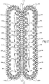
- injector 100 is intended to be representative, non-limiting example of a coiled tubing injector for running coiled tubing and pipe into and out of well bores. It has two, counter rotating drive chains 102 and 104. Each of the chains carries a plurality of gripping elements or grippers 106. The chains are thus sometimes also referred to as gripper chains. Each of the grippers on a chain is shaped to conform to, or complement, the outer diameter or outer surface curvature of tubing 109 (not shown in FIGURE 1 ) that will be gripped. The grippers on the respective chains come together in an area referred to as a gripping zone. As the tubing 109 passes through the injector it enters the gripping zone.
- the grippers from each of the chains cooperate to grip the tubing and substantially encircle the tubing to prevent it from being deformed.
- the gripping zone is substantially straight, with the sections of the respective chains within the gripping zone extending straight and parallel to each other.
- the center axis of the tubing is coincident with a central axis of the gripping zone.
- chains 102 and 104 revolve generally within a common plane.
- Injectors may comprise more than two drive chains.
- a second pair of drive chains can be arranged in an opposing fashion within a plane that is ninety degrees to the other plane, so that four gripping elements come together to engage the tubing as it passes through the injector.
- each drive chain of an injector is mounted or supported on at least two sprockets, one at the top and the other at the bottom of the injector.
- the upper and lower sprockets are, in practice, typically comprised of two spaced-apart sprockets that rotate around a common axis. In the representative example of FIGURE 1 , only one of each pair of sprockets 108 and 110 is visible.
- the upper sprockets in this example of an injector are driven.
- the drive sprockets are connected to a drive axle or shaft that is rotated by a drive system. Only one shaft, referenced by number 112, for upper drive sprocket pair 108, is visible in FIGURE 1 .
- the lower sprockets which are not visible in the figures, except for the end of shafts 114 and 116 to which they are connected, are not driven in this representative injector. They are referred to as idler sprockets.
- the lower sprockets could, however, be driven, either in place of or in addition to, the upper sprockets.
- additional sprockets could be added to the injector for the purpose of driving each of the chains.
- the sprockets are supported by a frame generally indicated by the reference number 118.
- the shafts for the upper sprockets are held on opposite ends by bearings. These bearings are located within two bearing housings 120 for shaft 112 and two bearing housings 122 for the other shaft that is not visible.
- the shafts for the lower sprockets are also held on opposite ends by bearings, which are mounted within moveable carriers that slide within slots with the frame. Only two front side bearings 124 and 126 can be seen in the figures. Allowing the shafts of the lower sprockets to move up and down permits the chains to be placed under constant tension by hydraulic cylinders 128 and 130.
- the frame 118 in this particular example of an injector, takes the form of a box, which is formed from two, parallel plates, of which plate 132 is visible in the drawing, and two parallel side plates 134 and 136.
- the frame supports sprockets, chains, skates and other elements of the injector, including a drive system and brakes 138 and 140.
- Each brake is coupled to a separate one of the drive shafts, on which the upper sprockets are mounted.
- the brakes are typically automatically activated in the event of a loss of hydraulic pressure.
- a drive system for the injector is comprised of at least one motor, typically hydraulically driven, but electric motors are also used.
- Injector 100 has two motors 142 and 144, one for each of the gripper chains. More motors could be added for driving each chain, for example by connecting them to the same shaft, or by connecting them to a separate sprocket on which the chain is mounted.
- the output of each motor is coupled to the shaft of the drive sprocket for the chain being driven by the motor, the motor thereby also being coupled with the chain.
- Each motor is coupled either directly or indirectly, such as through an arrangement of gears, an example of which is a planetary gear box 146. However, only one motor can be used.
- a hydraulic motor it is supplied, when the injector is put into operation, with pressurized hydraulic fluid received over hydraulic lines connected with a power pack, the power pack comprising a hydraulic pump powered by, for example, a diesel engine.
- the same power pack can be used to operate other hydraulic circuits, including hydraulic cylinders for generating a traction force, as described below.
- coiled tubing injector 100 includes for each chain 102 and 104 a skate 146 and 148, respectively, for pressing gripping elements 106 within the gripping zone against tubing 109. Note that the skates are visible only FIGURE 2 .
- the skates apply a normal force to the gripping elements, which transfer that force to the tubing to generate frictional force (referred to as the gripping force) for holding the tubing as it passes through the gripping zone.
- the greater the normal force the greater the traction force.
- the normal force is generated in part by a plurality of hydraulic cylinders. Each of the hydraulic cylinders is connected at a discrete position along the length of the gripping zone.
- one or more hydraulic cylinders can be arranged to push or pull the skates toward each other.
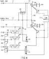
- FIGURES 3 and 4 are schematic diagrams of examples of representative embodiments of hydraulic circuits for use with the injectors such as the one shown in FIGURE 1 .
- drive motors 142 and 144 of FIGURE 1 correspond to hydraulic motors 202 and 204 in FIGURES 3 and 4 .
- the drive motors can be electric motors.
- Each drive motor has an output shaft 206a and 206b, respectively, coupled to a respective drive sprocket 208a and 208b.
- the drive motor may, optionally, be coupled through a gear box, such as a planetary gear box, and/or a brake.
- Each drive sprocket drives rotation of a different gripper chain (not shown).
- the circuit is driving two gripper chains.
- Pressurized hydraulic fluid from, for example, a power pack is supplied through supply line 210 (labelled "Power In”) to hydraulic drive motor 202, through branch 210a, and drive motor 204, through branch 210b.
- the hydraulic motors are connected to the return line 212 (labelled "Power Out”) through lines 212a and 212b, respectively.
- the drive motors are, thus, connected to the hydraulic power supply in parallel.
- Each of the timing motors 214 and 216 is coupled, respectively, to one of the two drive chains (not shown) so that it rotates at a speed that is in a fixed relationship to the rotational speed of the chain.
- each timing motor is connected, respectively, to the drive shafts of the respective one of the drive motors 202 and 204, as is shown in FIG. 1 .
- a timing motor could be indirectly connected or coupled, such as through gearing, to the drive motor or sprocket on which the chain is mounted.
- Each of the timing motors in this example, is comprised of a positive displacement hydraulic motor.
- the hydraulic timing motors 214 and 216 are connected in series in a closed circuit through a timing manifold 218.
- Each timing motor acts only to transfer force from one drive motor to the other when one is turning faster than the other.
- the timing manifold allows speed differences less than a predetermined amount between the motors to exist without building pressure within the circuit. Small differences between rotation speeds could be due to, for example, one gripping chain being slightly longer than the other. Such differences are insubstantial and do not indicate that, for example, one of the driven gripper chains is slipping on the tubing. In fact such differences may be desirable, as they accommodate, for example, slight difference in chain lengths and thus avoid tension that would otherwise have be relieved through slippage of one of the driven chains.
- the timing manifold allows a small, predetermined amount of hydraulic fluid to bleed across the circuit, thereby reducing pressure that would otherwise exist.
- the timing manifold is designed so that it is not able to relieve the pressure, and thus pressure will exist within the timing circuit. Pressure within the closed timing circuit acts to slow the faster turning timing motor, and thus also the drive motor to which it is connected, and speeds up the slower turning timing motor and the drive motor to which it is attached. If insubstantial speed difference between the independently driven chains is to be allowed, it is preferred to reduce or relieve pressure from within the circuit at those speed differences.
- the hydraulic timing circuit can be constructed without a timing manifold, or the timing manifold can be made adjustable and set to so that it does not reduce pressure within the circuit even at insubstantial speed differences.
- Pressure within the hydraulic timing circuit is, in the illustrated embodiment, also used to cause or to signal for an increase in the hydraulic pressure supplied to the coiled tubing injector's traction system, thus increasing the normal force applied the grippers on the chains.
- the exemplary embodiments of FIGURES 3 and 4 will tend to mitigate slippage, and enable the gripper to regain grip of the tubing in the event of an injector's traction system slipping
- the circuits of FIGURES 3 and 4 represent examples for making use of the pressure within the timing circuit as a control signal for changing or adjusting the hydraulic pressure being supplied to the traction system of a coiled tubing injector by a hydraulic traction pressure circuit, and thus adjusting the normal force being applied by the grippers.
- the two examples differ primarily in the source of a priority hydraulic pressure used for increasing the force supplied by the traction control circuit to the traction system, and thus of the grippers to the tubing.
- a priority pressure circuit is connected in parallel to the timing motors 214 and 216, and the timing manifold 218.
- the priority pressure circuit is comprised, in these examples, of directional valve 222.
- a pressure differential in the timing circuit in excess of a predetermined level causes directional valve 222 to shift, thereby connecting a source of priority hydraulic pressure to a hydraulic traction control circuit that controls the traction system.
- the traction system comprises three hydraulic cylinders 220a, 220b, and 220c that apply pressure to tubing being gripped by the traction system of the coiled tubing injector, the traction system being comprised of skates 146 and 148 of the representative injector illustrated by FIGURES 1 and 2 .
- the hydraulic traction pressure circuit is comprised of, in this example, the hydraulic cylinders and lines 224a, 224b, and 224c.
- the hydraulic traction pressure circuit supplies each hydraulic cylinder in parallel with hydraulic fluid at a predetermined set pressure.
- the pressure within the cylinders results in a normal force being applied to the tubing.
- the force causes skates 146 and 148 ( FIGURE 1 ) to move toward the tubing, resulting in a normal force being applied to the tubing by grippers on the gripper chaining moving along the skates.
- the drains of the cylinders are connected to a common drain line 226.
- the priority pressure circuit connects through check valves 228a, 228b, and 228c, respectively, to the traction control circuit to increase pressure to the priority pressure.
- the priority pressure is greater than the set pressure.
- the check valves prevent pressure from returning to the timing circuit and ensure that the traction circuits are isolated from each other. Traction pressure thus increases towards a maximum setting equal to the priority pressure while tubing is slipping, and otherwise remains at the set pressure.
- priority pressure is supplied through hydraulic line 230 by, for example, an injector-mounted hydraulic pressure supply.
- priority pressure is instead supplied from the main hydraulic power supply for the drive motors, which is through the circuit comprised of hydraulic lines 210 and 212.
- Shuttle valve 232 which is optional, transfers the higher of the two pressures on lines 210 and 212 to the directional valve 222 through a hydraulic line connecting the two.
- the line may, optionally include a manually operated valve 234 for disconnecting or turning off the main pressure supply to the priority pressure circuit.
- the hydraulic fluid from the shuttle valve may pass through a pressure reducing valve 236 to limit the supply pressure to the maximum traction force setting applied by the grippers.
- the pressurereducing valve is connected, in this example, to drain line 226.
Landscapes
- Engineering & Computer Science (AREA)
- Geology (AREA)
- Life Sciences & Earth Sciences (AREA)
- Mining & Mineral Resources (AREA)
- Environmental & Geological Engineering (AREA)
- Fluid Mechanics (AREA)
- Physics & Mathematics (AREA)
- General Life Sciences & Earth Sciences (AREA)
- Geochemistry & Mineralogy (AREA)
- Mechanical Engineering (AREA)
- Placing Or Removing Of Piles Or Sheet Piles, Or Accessories Thereof (AREA)
- Earth Drilling (AREA)
- Wind Motors (AREA)
- Fluid-Pressure Circuits (AREA)
Description
- "Coiled tubing injectors" are machines for running pipe into and out of well bores.
- Typically, the pipe is continuous, but injectors can also be used to raise and lower jointed pipe. Continuous pipe is generally referred to as coiled tubing since it is coiled onto a large reel when it is not in a well bore. The terms "tubing" and "pipe" are, when not modified by "continuous," "coiled" or "jointed," synonymous and encompass both continuous pipe, or coiled tubing, and jointed pipe. "Coiled tubing injector" and, shortened, "injector" refer to machines used for running any of these types of pipes or tubing. The name of the machine derives from the fact that it is typically used for coiled tubing and that, in pre-existing well bores, the pipe must be literally forced or "injected" into the well through a sliding seal to overcome the pressure of fluid within the well, until the weight of the pipe in the well exceeds the force produced by the pressure acting against the cross-sectional area of the pipe. However, once the weight of the pipe in the well overcomes the pressure, it must be supported by the injector. The process is reversed as the pipe is removed from the well.
- Coiled tubing is faster to run into and out of a well bore than conventional jointed or straight pipe and has traditionally been used primarily for circulating fluids into the well and other work over operations, but can be used for drilling. For drilling, a turbine motor is suspended at the end of the tubing and is driven by mud or drilling fluid pumped down the tubing. Coiled tubing has also been used as permanent tubing in production wells. These new uses of coiled tubing have been made possible by larger diameters and stronger pipe.
- Examples of coiled tubing injectors include those shown and described in
U.S. Pat. Nos. 5,309,990 ,6,059,029 , and6,173,769 . - A conventional coiled tubing injector has two continuous chains, though more than two can be used. The chains are mounted on sprockets to form elongated loops that counter rotate. A drive system applies torque to the sprockets to cause them to rotate, resulting in rotation of the chains. In most injectors, chains are arranged in opposing pairs, with the pipe being held between the chains. Grippers carried by each chain come together on opposite sides of the tubing and are pressed against the tubing. The injector thereby continuously grips a length of the tubing as it is being moved in and out of the well bore. The "grip zone" or "gripping zone" refers to the zone in which grippers come into contact with a length of tubing passing through the injector.
- Several different arrangements can be used to push the grippers against the tubing. One common arrangement uses a skate to apply an even force to the back of the grippers as they pass through the grip zone. In one example, each gripper has a cylindrical roller, or multiple rollers with the same axis of rotation, mounted to its back. The rollers roll along a continuous, planar surface formed by the skate as the grippers pass through the gripping zone. By properly positioning the skate with respect to the tubing, the skate can push the grippers against the tubing with force or pressure that is normal to the tubing. In an alternative arrangement rollers are mounted on the skate, and the back of the grippers have a flat or planar surface that ride along the rollers. The axes of the rollers are co-planar, so that the rollers engage the back of the skates in the same plane, thus effectively presenting a planar rolling surface on which the grippers may roll.
- A coiled tubing injector applies a normal force to its grippers. The normal force creates through friction an axial force along the longitudinal axis of the tubing. The amount of traction between the grippers and the tubing is determined, at least in part, by the amount of this force. In order to control the amount of the normal force, skates for opposing chains are typically pulled toward each other by a traction system comprising hydraulic pistons or a similar mechanism, thereby forcing the gripper elements against the tubing. Alternatively, skates are pushed toward each other. The force applied by the traction system to the chains, and thus to the tubing against which the chains are pressed, is adjustable to take into account different operating conditions.
- If the force at which a traction system for a coiled tubing injector is set is insufficient for any reason, the injector will lose grip on the tubing. When independently driven chains are used in coiled tubing injectors, there is also a risk that one or more of the chains will begin to slip on the tubing before the other. Once a chain begins to slip on the tubing, the type of friction changes from static to dynamic and the traction of the slipping chain is greatly diminished. When grip is lost, damage to the coiled tubing is possible. Damage is more likely the further the tubing is allowed to slip in the injector chains. When the tubing speed increases, it is more difficult to regain grip and the potential of damage to the tubing, machinery, and the well increases.
-
US 2012/0073833 discloses a coiled tubing injector comprising a pair of driven continuous chains each provided with a multiplicity of grippers for gripping a portion of a length of coiled tubing. In one embodiment, each continuous chain is driven by a motor. The motors are powered hydraulically through a hydraulic circuit in parallel, such that if one chain starts slipping on the coiled tubing, resistance on the hydraulic circuit is decreased and the speed of the slipping continuous chain would increase. However, a system is employed comprising a timing motor mechanically coupled to and driven by each of the motors. The timing motors are arranged in series in a hydraulic circuit, such that if there is a sufficient difference in speed between the timing motors, it can be inferred one of the chains is slipping, whereupon the timing motors equalise their speeds as they are arranged in a series hydraulic circuit. -
US 5,850,874 discloses a coiled tubing injector comprising a pair of injector blocks each containing driven chains, each continuous chain arranged on upper and lower toothed wheels. Rams are used to move the injector blocks towards and away from coiled tubing to grip and release the coiled tubing. In one mode, the system may be operated wherein the control unit inserts the tubing at a predetermined speed and maintains the radial pressure on the tubing within predetermined limits. If a slippage of the tubing through the injector head is detected, such as when it is determined that the actual speed of the tubing is greater than the speed of the injector head, then the control unit causes the RAMS to exert additional pressure on the tubing to provide greater gripping force to the blocks. If the slippage continues even after the gripping force has reached the maximum limit defined for the tubing and the back tension on the tubing is within a desired range, the control unit may be programmed to activate an alarm and/or to shut down the operation until the problem is resolved. - In accordance with the present invention, there is provided a coiled tubing injector according to claim 1.
- Other optional, advantageous or preferable features of the coiled tubing injector of the invention are set out in dependent claims 2 to 11.
- The present invention also provides a method of controlling traction of a coiled tubing injector according to claim 12.
- Other optional, advantageous or preferable features of the coiled tubing injector of the invention are set out in dependent claims 12 to 20.
- Such a coiled tubing injector is capable of detecting chain slippage and increasing traction pressure in response to it without intervention of an operator. It can be used to particular advantage in situations in which the injector is located remotely from an operator, such as on top of a riser high above well, where an operator cannot easily see slippage starting or react to it quickly.
- In one exemplary embodiment the hydraulic timing circuit is comprised of a hydraulic timing motor coupled to each one of a coiled tubing injector's two or more chains. The hydraulic timing motors are connected in a hydraulic circuit so that pressure is generated within the circuit when the speed at which one of independently driving gripper chains turns one of the timing motors is at least a predetermined amount faster than the speed that another one of the independently driven chains turns the other timing motor. The pressure within the timing circuit, when it reaches or exceeds a predetermined amount, is used as a signal to cause a traction system on the coiled tubing injector to increase traction force applied by the chain to the tubing. For example, the pressure within the timing circuit can be used to shift or open the valve to increase hydraulic pressure supplied to the traction control system by, for example, connecting in a supply of hydraulic fluid under greater pressure.
-
-
FIGURE 1 is a perspective view of a representative coiled tubing injector. -
FIGURE 2 is a perspective view of a representative coiled tubing injector. -
FIGURE 3 is a schematic diagram of a first embodiment of hydraulic circuit for automatically controlling traction pressure of a coiled tubing injector in response to detecting chain slippage. -
FIGURE 4 is a schematic diagram of a second embodiment of hydraulic circuit for automatically controlling traction pressure of a coiled tubing injector in response to detecting chain slippage. - In the following description, like numbers refer to like elements.
- Referring to
FIGURES 1 and2 ,injector 100 is intended to be representative, non-limiting example of a coiled tubing injector for running coiled tubing and pipe into and out of well bores. It has two, counter rotatingdrive chains grippers 106. The chains are thus sometimes also referred to as gripper chains. Each of the grippers on a chain is shaped to conform to, or complement, the outer diameter or outer surface curvature of tubing 109 (not shown inFIGURE 1 ) that will be gripped. The grippers on the respective chains come together in an area referred to as a gripping zone. As thetubing 109 passes through the injector it enters the gripping zone. On the gripping zone, the grippers from each of the chains cooperate to grip the tubing and substantially encircle the tubing to prevent it from being deformed. In this example, the gripping zone is substantially straight, with the sections of the respective chains within the gripping zone extending straight and parallel to each other. The center axis of the tubing is coincident with a central axis of the gripping zone. In the illustrated example, which has only two chains,chains FIGURE 1 ,chains - Referring now only to
FIGURE 1 , each drive chain of an injector is mounted or supported on at least two sprockets, one at the top and the other at the bottom of the injector. The upper and lower sprockets are, in practice, typically comprised of two spaced-apart sprockets that rotate around a common axis. In the representative example ofFIGURE 1 , only one of each pair ofsprockets number 112, for upperdrive sprocket pair 108, is visible inFIGURE 1 . The lower sprockets, which are not visible in the figures, except for the end ofshafts - The sprockets are supported by a frame generally indicated by the
reference number 118. The shafts for the upper sprockets are held on opposite ends by bearings. These bearings are located within two bearinghousings 120 forshaft 112 and two bearinghousings 122 for the other shaft that is not visible. The shafts for the lower sprockets are also held on opposite ends by bearings, which are mounted within moveable carriers that slide within slots with the frame. Only twofront side bearings hydraulic cylinders - The
frame 118, in this particular example of an injector, takes the form of a box, which is formed from two, parallel plates, of whichplate 132 is visible in the drawing, and twoparallel side plates brakes - A drive system for the injector is comprised of at least one motor, typically hydraulically driven, but electric motors are also used.
Injector 100 has twomotors planetary gear box 146. However, only one motor can be used. It can drive either just one chain (with the other not being driven) or both chains by coupling it, directly or indirectly, through gearing a drive sprocket for each chain. Examples of such gearing include a differential gear drive with multiple outputs or by gears coupling the two drive sockets. If a hydraulic motor is used, it is supplied, when the injector is put into operation, with pressurized hydraulic fluid received over hydraulic lines connected with a power pack, the power pack comprising a hydraulic pump powered by, for example, a diesel engine. The same power pack can be used to operate other hydraulic circuits, including hydraulic cylinders for generating a traction force, as described below. - Referring to
FIGURE 1 andFIGURE 2 ,coiled tubing injector 100 includes for eachchain 102 and 104 askate gripping elements 106 within the gripping zone againsttubing 109. Note that the skates are visible onlyFIGURE 2 . The skates apply a normal force to the gripping elements, which transfer that force to the tubing to generate frictional force (referred to as the gripping force) for holding the tubing as it passes through the gripping zone. The greater the normal force, the greater the traction force. The normal force is generated in part by a plurality of hydraulic cylinders. Each of the hydraulic cylinders is connected at a discrete position along the length of the gripping zone. They generate equal forces to pull together the skates at multiple points along their lengths, thereby applying uniform gripping pressure against thetubing 109 along the length of the skates. In alternative embodiments, one or more hydraulic cylinders can be arranged to push or pull the skates toward each other. -
FIGURES 3 and4 are schematic diagrams of examples of representative embodiments of hydraulic circuits for use with the injectors such as the one shown inFIGURE 1 . In these schematics, drivemotors FIGURE 1 correspond tohydraulic motors FIGURES 3 and4 . However, in alternate embodiments, the drive motors can be electric motors. Each drive motor has anoutput shaft respective drive sprocket - Pressurized hydraulic fluid from, for example, a power pack (not shown) is supplied through supply line 210 (labelled "Power In") to
hydraulic drive motor 202, throughbranch 210a, and drivemotor 204, throughbranch 210b. The hydraulic motors are connected to the return line 212 (labelled "Power Out") throughlines - Each of the timing
motors drive motors FIG. 1 . However, a timing motor could be indirectly connected or coupled, such as through gearing, to the drive motor or sprocket on which the chain is mounted. Each of the timing motors, in this example, is comprised of a positive displacement hydraulic motor. - In this example, the
hydraulic timing motors timing manifold 218. Each timing motor acts only to transfer force from one drive motor to the other when one is turning faster than the other. The timing manifold allows speed differences less than a predetermined amount between the motors to exist without building pressure within the circuit. Small differences between rotation speeds could be due to, for example, one gripping chain being slightly longer than the other. Such differences are insubstantial and do not indicate that, for example, one of the driven gripper chains is slipping on the tubing. In fact such differences may be desirable, as they accommodate, for example, slight difference in chain lengths and thus avoid tension that would otherwise have be relieved through slippage of one of the driven chains. The timing manifold allows a small, predetermined amount of hydraulic fluid to bleed across the circuit, thereby reducing pressure that would otherwise exist. However, when the speed difference in the timing motors grows to an amount that indicates that one of the gripper chains could be slipping relative to the tubing, the timing manifold is designed so that it is not able to relieve the pressure, and thus pressure will exist within the timing circuit. Pressure within the closed timing circuit acts to slow the faster turning timing motor, and thus also the drive motor to which it is connected, and speeds up the slower turning timing motor and the drive motor to which it is attached. If insubstantial speed difference between the independently driven chains is to be allowed, it is preferred to reduce or relieve pressure from within the circuit at those speed differences. However, in the alternative, the hydraulic timing circuit can be constructed without a timing manifold, or the timing manifold can be made adjustable and set to so that it does not reduce pressure within the circuit even at insubstantial speed differences. - Conventional coiled tubing injectors grip tubing with a traction system that applies a normal force to the tubing. The amount of force can be adjusted by setting a hydraulic circuit supplying hydraulic pressure to the traction system. Should a setting be insufficient it will cause the injector to lose grip on the tubing. When grip is lost, damage to the coiled tubing is possible and will be more likely the further the tubing is allowed to slip in the injector chains. In extreme cases of slipping, the speed at which the tubing slips relative to the gripper chain increases, thus making it more difficult to regain grip and increasing the potential of damage to the tubing, machinery, and the well. As coiled tubing injectors are sometimes mounted on top of tall risers connected to a wellhead, operators located far away may not be able to detect slips and make the proper adjustments to correct slips in time to avoid the related tubing slip damages and dangers.
- Pressure within the hydraulic timing circuit is, in the illustrated embodiment, also used to cause or to signal for an increase in the hydraulic pressure supplied to the coiled tubing injector's traction system, thus increasing the normal force applied the grippers on the chains. By slowing the slipping gripper chain and automatically and rapidly increasing gripping force on the tubing as the slipping begins to occur, the exemplary embodiments of
FIGURES 3 and4 will tend to mitigate slippage, and enable the gripper to regain grip of the tubing in the event of an injector's traction system slipping - The circuits of
FIGURES 3 and4 represent examples for making use of the pressure within the timing circuit as a control signal for changing or adjusting the hydraulic pressure being supplied to the traction system of a coiled tubing injector by a hydraulic traction pressure circuit, and thus adjusting the normal force being applied by the grippers. The two examples differ primarily in the source of a priority hydraulic pressure used for increasing the force supplied by the traction control circuit to the traction system, and thus of the grippers to the tubing. - In both examples, a priority pressure circuit is connected in parallel to the timing
motors timing manifold 218. The priority pressure circuit is comprised, in these examples, ofdirectional valve 222. A pressure differential in the timing circuit in excess of a predetermined level causesdirectional valve 222 to shift, thereby connecting a source of priority hydraulic pressure to a hydraulic traction control circuit that controls the traction system. In this representative example, the traction system comprises threehydraulic cylinders skates FIGURES 1 and2 . The hydraulic traction pressure circuit is comprised of, in this example, the hydraulic cylinders andlines FIGURES 1 and2 , the force causesskates 146 and 148 (FIGURE 1 ) to move toward the tubing, resulting in a normal force being applied to the tubing by grippers on the gripper chaining moving along the skates. The drains of the cylinders are connected to acommon drain line 226. The priority pressure circuit connects throughcheck valves - In the example of
FIGURE 3 , priority pressure is supplied throughhydraulic line 230 by, for example, an injector-mounted hydraulic pressure supply. In the example ofFIGURE 4 , priority pressure is instead supplied from the main hydraulic power supply for the drive motors, which is through the circuit comprised ofhydraulic lines Shuttle valve 232, which is optional, transfers the higher of the two pressures onlines directional valve 222 through a hydraulic line connecting the two. The line may, optionally include a manually operatedvalve 234 for disconnecting or turning off the main pressure supply to the priority pressure circuit. Furthermore, the hydraulic fluid from the shuttle valve, may pass through apressure reducing valve 236 to limit the supply pressure to the maximum traction force setting applied by the grippers. The pressurereducing valve is connected, in this example, to drainline 226.
Claims (20)
- A coiled tubing injector (100) comprising:at least two gripper chains (102, 104), each with a plurality of grippers (106) for gripping coiled tubing (109) within a gripping zone between the chains;a traction system comprising a hydraulic traction pressure circuit (224a, 224b, 224c) for generating a gripping force applied to the at least two chains;a hydraulic timing circuit (214, 216, 218) coupled with the at least two gripper chains, the hydraulic timing circuit adapted for detecting a difference in relative speeds of the at least two gripper chains (102, 104) is greater than a predetermined amount, characterised in that a hydraulic pressure signal is generated by the hydraulic timing circuit when the difference in relative speeds of the at least two gripper chains is greater than a predetermined amount, whereupon the hydraulic pressure signal actuates a valve (222) to increase hydraulic pressure supplied to the hydraulic traction pressure circuit (224a, 224b, 224c) to increase the gripping force in response to the hydraulic pressure signal.
- The coiled tubing injector of claim 1, wherein each of the at least two gripper chains (102, 104) is independently driven.
- The coiled tubing injector of claim 1 or 2, wherein the hydraulic timing circuit (214, 216, 218) comprises a timing circuit comprising at least two hydraulic timing motors (214, 216), each coupled to a separate one of the at least two gripper chains (102, 104), the hydraulic timing motors being connected within the hydraulic timing circuit in a manner to generate pressure within the hydraulic timing circuit when the speed at which one of the at least two gripper chains turns one of the timing motors is at least a predetermined amount faster than the speed that another one of the independently driven gripper chains turns the other timing motor.
- The coiled tubing injector of claim 3, wherein the at least two hydraulic timing motors (214, 216) are connected in series in a closed circuit through a timing manifold (218) that permits speed differences between the at least two hydraulic timing motors less than a predetermined amount to exist without building pressure within the hydraulic timing circuit by allowing a small, predetermined amount of hydraulic fluid to bleed across the circuit, thereby reducing pressure that would otherwise exist.
- The coiled tubing injector of claim 3 or 4, wherein the pressure within the timing circuit is used as the hydraulic pressure signal.
- The coiled tubing injector of any preceding claim, wherein in use actuating the valve (222) to increase hydraulic pressure supplied to the hydraulic traction pressure circuit (224a, 224b, 224c) connects to the hydraulic traction pressure circuit a supply of hydraulic fluid under greater pressure.
- The coiled tubing injector of claim 6, wherein the supply of hydraulic fluid under greater pressure is from an injector-mounted hydraulic pressure supply.
- The coiled tubing injector of claim 6, wherein the supply of hydraulic fluid under greater pressure is from a main hydraulic power supply for one or more hydraulic drive motors (142, 144; 202, 204) coupled with the at least two gripper chains (102, 104).
- The coiled tubing injector of claim 8, wherein the main hydraulic power supply comprises a power-in line (210) having hydraulic fluid at a first pressure and a power-out line (212) having hydraulic fluid at a second pressure with a shuttle valve (232) arranged therebetween such that, in use, the hydraulic fluid at the higher of the first and second pressures is directed to said actuating valve (222).
- The coiled tubing injector of claim 9, wherein the hydraulic fluid directed by the shuttle valve (232) passes through a pressure reducing valve (236) before reaching the actuating valve (222).
- The coiled tubing injector of any preceding claim, further comprising:a plurality of skates (146, 148), one for each of the at least two gripper chains (102, 104), for pressing the plurality of grippers (106) of the chain within the gripping zone toward the coiled tubing; anda plurality of hydraulic cylinders (220a, 220b, 220c) coupled to the plurality of skates the at discrete position along the length of the gripping zone for applying a normal force to the gripping elements through the skates.
- A method of controlling traction of a coiled tubing injector (100), the coiled tubing injector having least two gripper chains (102, 104), each with a plurality of grippers (106) for gripping coiled tubing (109) within a gripping zone between the chains, the method comprising:driving each of the gripper chains (102, 104) independently;passing coiled tubing between the at least two gripper chains;generating with a hydraulic traction pressure circuit (224a, 224b, 224c) a gripping force and applying the gripping force to the at least two gripper chains;detecting with a hydraulic timing circuit (214, 216, 218) coupled with each of the gripper chains a difference in relative speeds of the at least two gripper chains indicating that one chain is beginning to slip relative to the coiled tubing; characterised by generating a hydraulic pressure signal when the difference is detected;the hydraulic pressure signal actuating a valve (222);actuation of the valve (222) inducing an increase in hydraulic pressure supplied to the hydraulic traction pressure circuit (224a, 224b, 224c), increasing the gripping force applied by the at least two gripper chains (102, 104) to the coiled tubing in response to the hydraulic pressure signal.
- The method of claim 12, wherein the hydraulic timing circuit (214, 216, 218) comprises at least two hydraulic timing motors (214, 218), each coupled to a separate one of the at least two gripper chains (102, 104), the hydraulic timing motors being coupled for generating pressure within the hydraulic timing circuit when the speed at which one of the at least two gripper chains turns one of the timing motors is at least a predetermined amount faster than the speed that another one of the independently driven chains turns the other timing motor.
- The method of claim 13, wherein the at least two hydraulic timing motors (214, 218) are connected in series in a closed circuit through a timing manifold (218) that permits speed differences between the at least two hydraulic timing motors less than a predetermined amount to exist without building pressure within the hydraulic timing circuit by allowing a small, predetermined amount of hydraulic fluid to bleed across the circuit, thereby reducing pressure that would otherwise exist.
- The method of any of claims 12 to 14, wherein increasing gripping force applied by the at least two gripper chains (102, 104) to the coiled tubing in response to the hydraulic pressure signal comprises increasing the pressure of hydraulic fluid supplied to at least one hydraulic cylinder (220a, 220b, 220c) generating the gripping force.
- The method of claim 12 to 15, wherein the supply of hydraulic fluid under greater pressure is from an injector-mounted hydraulic pressure supply.
- The method of claim 16, wherein the supply of hydraulic fluid under greater pressure is from a main hydraulic power supply for one or more hydraulic drive motors (142, 144; 202, 204) coupled with the at least two gripper chains (102, 104).
- The method of claim 17, wherein the main hydraulic power supply comprises a power-in line (210) having hydraulic fluid at a first pressure and a power-out line (212) having hydraulic fluid at a second pressure with a shuttle valve (232) arranged therebetween the method further comprising the step of the shuttle valve (232) directing the hydraulic fluid at the higher of the first and second pressures to said actuating valve (222).
- The method of claim 18, wherein the hydraulic fluid directed by the shuttle valve (232) passes through a pressure reducing valve (236) before reaching the actuating valve (222).
- The method of any of claims 12-19, wherein, the coiled tubing injector comprises:a plurality of skates (146, 148), one for each of the at least two gripper chains (102, 104), for pressing the plurality gripping elements (106) of the chain within the gripping zone toward the coiled tubing; anda plurality of hydraulic cylinders (220a, 220b, 220c) coupled to the plurality of skates the at discrete position along the length of the gripping zone for applying a normal force to the gripping elements through the skates.
Applications Claiming Priority (2)
| Application Number | Priority Date | Filing Date | Title |
|---|---|---|---|
| US201361861352P | 2013-08-01 | 2013-08-01 | |
| PCT/US2014/049493 WO2015017835A2 (en) | 2013-08-01 | 2014-08-01 | Coiled tubing injector with hydraulic traction slip mitigation circuit |
Publications (2)
| Publication Number | Publication Date |
|---|---|
| EP3027848A2 EP3027848A2 (en) | 2016-06-08 |
| EP3027848B1 true EP3027848B1 (en) | 2022-10-26 |
Family
ID=51355683
Family Applications (1)
| Application Number | Title | Priority Date | Filing Date |
|---|---|---|---|
| EP14752528.1A Active EP3027848B1 (en) | 2013-08-01 | 2014-08-01 | Coiled tubing injector with hydraulic traction slip mitigation circuit |
Country Status (5)
| Country | Link |
|---|---|
| US (1) | US10024123B2 (en) |
| EP (1) | EP3027848B1 (en) |
| CN (1) | CN105431611B (en) |
| CA (1) | CA2919175C (en) |
| WO (1) | WO2015017835A2 (en) |
Families Citing this family (39)
| Publication number | Priority date | Publication date | Assignee | Title |
|---|---|---|---|---|
| WO2016044566A1 (en) * | 2014-09-17 | 2016-03-24 | Premier Coil Solutions, Inc. | Methods and system for independently controlling injector head drive motor speeds |
| US10323471B2 (en) * | 2016-03-11 | 2019-06-18 | Baker Hughes, A Ge Company, Llc | Intelligent injector control system, coiled tubing unit having the same, and method |
| CN105840122B (en) * | 2016-05-12 | 2017-12-08 | 山东科瑞机械制造有限公司 | A kind of four motor driven continuous tube injection heads |
| US11624326B2 (en) | 2017-05-21 | 2023-04-11 | Bj Energy Solutions, Llc | Methods and systems for supplying fuel to gas turbine engines |
| US11560845B2 (en) | 2019-05-15 | 2023-01-24 | Bj Energy Solutions, Llc | Mobile gas turbine inlet air conditioning system and associated methods |
| US11002189B2 (en) | 2019-09-13 | 2021-05-11 | Bj Energy Solutions, Llc | Mobile gas turbine inlet air conditioning system and associated methods |
| US12065968B2 (en) | 2019-09-13 | 2024-08-20 | BJ Energy Solutions, Inc. | Systems and methods for hydraulic fracturing |
| US10895202B1 (en) | 2019-09-13 | 2021-01-19 | Bj Energy Solutions, Llc | Direct drive unit removal system and associated methods |
| US10815764B1 (en) | 2019-09-13 | 2020-10-27 | Bj Energy Solutions, Llc | Methods and systems for operating a fleet of pumps |
| CA3197583A1 (en) | 2019-09-13 | 2021-03-13 | Bj Energy Solutions, Llc | Fuel, communications, and power connection systems and related methods |
| US11015594B2 (en) | 2019-09-13 | 2021-05-25 | Bj Energy Solutions, Llc | Systems and method for use of single mass flywheel alongside torsional vibration damper assembly for single acting reciprocating pump |
| CA3092868A1 (en) | 2019-09-13 | 2021-03-13 | Bj Energy Solutions, Llc | Turbine engine exhaust duct system and methods for noise dampening and attenuation |
| CA3092865C (en) | 2019-09-13 | 2023-07-04 | Bj Energy Solutions, Llc | Power sources and transmission networks for auxiliary equipment onboard hydraulic fracturing units and associated methods |
| CA3092829C (en) | 2019-09-13 | 2023-08-15 | Bj Energy Solutions, Llc | Methods and systems for supplying fuel to gas turbine engines |
| US11604113B2 (en) | 2019-09-13 | 2023-03-14 | Bj Energy Solutions, Llc | Fuel, communications, and power connection systems and related methods |
| US11708829B2 (en) | 2020-05-12 | 2023-07-25 | Bj Energy Solutions, Llc | Cover for fluid systems and related methods |
| US10968837B1 (en) | 2020-05-14 | 2021-04-06 | Bj Energy Solutions, Llc | Systems and methods utilizing turbine compressor discharge for hydrostatic manifold purge |
| US11428165B2 (en) | 2020-05-15 | 2022-08-30 | Bj Energy Solutions, Llc | Onboard heater of auxiliary systems using exhaust gases and associated methods |
| US11208880B2 (en) | 2020-05-28 | 2021-12-28 | Bj Energy Solutions, Llc | Bi-fuel reciprocating engine to power direct drive turbine fracturing pumps onboard auxiliary systems and related methods |
| US11109508B1 (en) | 2020-06-05 | 2021-08-31 | Bj Energy Solutions, Llc | Enclosure assembly for enhanced cooling of direct drive unit and related methods |
| US11208953B1 (en) | 2020-06-05 | 2021-12-28 | Bj Energy Solutions, Llc | Systems and methods to enhance intake air flow to a gas turbine engine of a hydraulic fracturing unit |
| US10954770B1 (en) | 2020-06-09 | 2021-03-23 | Bj Energy Solutions, Llc | Systems and methods for exchanging fracturing components of a hydraulic fracturing unit |
| US11066915B1 (en) | 2020-06-09 | 2021-07-20 | Bj Energy Solutions, Llc | Methods for detection and mitigation of well screen out |
| US11111768B1 (en) | 2020-06-09 | 2021-09-07 | Bj Energy Solutions, Llc | Drive equipment and methods for mobile fracturing transportation platforms |
| US11933153B2 (en) | 2020-06-22 | 2024-03-19 | Bj Energy Solutions, Llc | Systems and methods to operate hydraulic fracturing units using automatic flow rate and/or pressure control |
| US11125066B1 (en) | 2020-06-22 | 2021-09-21 | Bj Energy Solutions, Llc | Systems and methods to operate a dual-shaft gas turbine engine for hydraulic fracturing |
| US11939853B2 (en) | 2020-06-22 | 2024-03-26 | Bj Energy Solutions, Llc | Systems and methods providing a configurable staged rate increase function to operate hydraulic fracturing units |
| US11028677B1 (en) | 2020-06-22 | 2021-06-08 | Bj Energy Solutions, Llc | Stage profiles for operations of hydraulic systems and associated methods |
| US11466680B2 (en) | 2020-06-23 | 2022-10-11 | Bj Energy Solutions, Llc | Systems and methods of utilization of a hydraulic fracturing unit profile to operate hydraulic fracturing units |
| US11473413B2 (en) | 2020-06-23 | 2022-10-18 | Bj Energy Solutions, Llc | Systems and methods to autonomously operate hydraulic fracturing units |
| US11149533B1 (en) | 2020-06-24 | 2021-10-19 | Bj Energy Solutions, Llc | Systems to monitor, detect, and/or intervene relative to cavitation and pulsation events during a hydraulic fracturing operation |
| US11220895B1 (en) | 2020-06-24 | 2022-01-11 | Bj Energy Solutions, Llc | Automated diagnostics of electronic instrumentation in a system for fracturing a well and associated methods |
| US11193360B1 (en) | 2020-07-17 | 2021-12-07 | Bj Energy Solutions, Llc | Methods, systems, and devices to enhance fracturing fluid delivery to subsurface formations during high-pressure fracturing operations |
| US20220290514A1 (en) * | 2021-03-10 | 2022-09-15 | Premier Coil Solutions, Inc. | Automatic Coiled Tubing Injector Chain Management System |
| US11639654B2 (en) | 2021-05-24 | 2023-05-02 | Bj Energy Solutions, Llc | Hydraulic fracturing pumps to enhance flow of fracturing fluid into wellheads and related methods |
| US11566479B1 (en) | 2021-11-03 | 2023-01-31 | Halliburton Energy Services, Inc. | Gripper control in a coiled tubing system |
| CN114212627A (en) * | 2021-11-24 | 2022-03-22 | 山西江淮重工有限责任公司 | Underground pipeline winding and unwinding devices |
| US11661804B1 (en) | 2022-08-23 | 2023-05-30 | National Oilwell Varco, L.P. | Coiled tubing injector with reactive chain tension |
| US20240287858A1 (en) * | 2023-02-27 | 2024-08-29 | Nabors Drilling Technologies Usa, Inc. | Wrench with self-intensifier |
Family Cites Families (11)
| Publication number | Priority date | Publication date | Assignee | Title |
|---|---|---|---|---|
| US3132622A (en) * | 1961-11-08 | 1964-05-12 | Tacoma Boatbuilding Co Inc | Two-sided hydraulic system |
| US3841407A (en) * | 1973-01-02 | 1974-10-15 | J Bozeman | Coil tubing unit |
| US5325668A (en) * | 1988-06-10 | 1994-07-05 | S.I.T.I. Societa Impianti Termoelettrici Industriali S.P.A. | Method and apparatus for hydraulic pressing |
| US5158781A (en) * | 1989-03-02 | 1992-10-27 | The Conair Group, Inc. | Traction apparatus for tubular material |
| US5850874A (en) * | 1995-03-10 | 1998-12-22 | Burge; Philip | Drilling system with electrically controlled tubing injection system |
| US5775417A (en) * | 1997-03-24 | 1998-07-07 | Council; Malcolm N. | Coiled tubing handling apparatus |
| US6968905B2 (en) * | 2003-03-18 | 2005-11-29 | Schlumberger Technology Corporation | Distributed control system |
| US7150330B2 (en) * | 2004-05-06 | 2006-12-19 | Halliburton Energy Services, Inc. | Hydraulic circuit and method for operating a gripping device |
| US8544536B2 (en) * | 2010-09-24 | 2013-10-01 | National Oilwell Varco, L.P. | Coiled tubing injector with limited slip chains |
| US8651190B2 (en) * | 2010-10-28 | 2014-02-18 | Hydril Usa Manufacturing Llc | Shear boost triggering and bottle reducing system and method |
| CN202832281U (en) * | 2012-09-03 | 2013-03-27 | 中国石油天然气集团公司 | Hydraulic pressure foldable coiled tubing guiding device |
-
2014
- 2014-08-01 WO PCT/US2014/049493 patent/WO2015017835A2/en active Application Filing
- 2014-08-01 CN CN201480043208.XA patent/CN105431611B/en active Active
- 2014-08-01 CA CA2919175A patent/CA2919175C/en active Active
- 2014-08-01 US US14/908,272 patent/US10024123B2/en active Active
- 2014-08-01 EP EP14752528.1A patent/EP3027848B1/en active Active
Also Published As
| Publication number | Publication date |
|---|---|
| CA2919175C (en) | 2021-03-09 |
| EP3027848A2 (en) | 2016-06-08 |
| WO2015017835A2 (en) | 2015-02-05 |
| CA2919175A1 (en) | 2015-02-05 |
| US10024123B2 (en) | 2018-07-17 |
| WO2015017835A3 (en) | 2015-04-02 |
| CN105431611A (en) | 2016-03-23 |
| US20160186509A1 (en) | 2016-06-30 |
| CN105431611B (en) | 2019-03-08 |
Similar Documents
| Publication | Publication Date | Title |
|---|---|---|
| EP3027848B1 (en) | Coiled tubing injector with hydraulic traction slip mitigation circuit | |
| US9151122B2 (en) | Coiled tubing injector with limited slip chains | |
| CA2818611C (en) | Coiled tubing injector with strain relief | |
| US4655291A (en) | Injector for coupled pipe | |
| CA2236234C (en) | Coiled tubing injector | |
| US8875365B2 (en) | Tongs with low torque at high pressure | |
| EP2744969B1 (en) | Device for activation of gripping jaws in continuously rotating torque tongs for use under pulling and opening of threaded connections | |
| US20030034162A1 (en) | Well string injection system and method | |
| US11134623B2 (en) | Feeding apparatus for a tree harvester | |
| CN111637173B (en) | Hydraulic meshing sprocket clutch device | |
| US20050205267A1 (en) | Coil tubing injector for injecting tubings of various diameters | |
| CN103387161B (en) | A kind of worm and gear driving roller type device | |
| CN214393944U (en) | A clamping device for municipal pipeline construction | |
| RU2632616C2 (en) | Injector of coiled tubing with tension relief | |
| CN204324782U (en) | Cable work rope woolding device | |
| CN206332380U (en) | Liner cable laying machine | |
| CA2461977A1 (en) | Coil tubing injector for injecting tubings of various diameters | |
| CN201301190Y (en) | Wire arranging mechanism of roller well testing winch | |
| CN115584940A (en) | Spinner clamp clamping device for adjusting clamping force and iron roughneck |
Legal Events
| Date | Code | Title | Description |
|---|---|---|---|
| PUAI | Public reference made under article 153(3) epc to a published international application that has entered the european phase |
Free format text: ORIGINAL CODE: 0009012 |
|
| 17P | Request for examination filed |
Effective date: 20160126 |
|
| AK | Designated contracting states |
Kind code of ref document: A2 Designated state(s): AL AT BE BG CH CY CZ DE DK EE ES FI FR GB GR HR HU IE IS IT LI LT LU LV MC MK MT NL NO PL PT RO RS SE SI SK SM TR |
|
| AX | Request for extension of the european patent |
Extension state: BA ME |
|
| DAX | Request for extension of the european patent (deleted) | ||
| STAA | Information on the status of an ep patent application or granted ep patent |
Free format text: STATUS: EXAMINATION IS IN PROGRESS |
|
| 17Q | First examination report despatched |
Effective date: 20170713 |
|
| STAA | Information on the status of an ep patent application or granted ep patent |
Free format text: STATUS: EXAMINATION IS IN PROGRESS |
|
| GRAP | Despatch of communication of intention to grant a patent |
Free format text: ORIGINAL CODE: EPIDOSNIGR1 |
|
| STAA | Information on the status of an ep patent application or granted ep patent |
Free format text: STATUS: GRANT OF PATENT IS INTENDED |
|
| INTG | Intention to grant announced |
Effective date: 20220629 |
|
| GRAS | Grant fee paid |
Free format text: ORIGINAL CODE: EPIDOSNIGR3 |
|
| GRAA | (expected) grant |
Free format text: ORIGINAL CODE: 0009210 |
|
| STAA | Information on the status of an ep patent application or granted ep patent |
Free format text: STATUS: THE PATENT HAS BEEN GRANTED |
|
| AK | Designated contracting states |
Kind code of ref document: B1 Designated state(s): AL AT BE BG CH CY CZ DE DK EE ES FI FR GB GR HR HU IE IS IT LI LT LU LV MC MK MT NL NO PL PT RO RS SE SI SK SM TR |
|
| REG | Reference to a national code |
Ref country code: GB Ref legal event code: FG4D |
|
| REG | Reference to a national code |
Ref country code: CH Ref legal event code: EP |
|
| REG | Reference to a national code |
Ref country code: DE Ref legal event code: R096 Ref document number: 602014085328 Country of ref document: DE |
|
| REG | Reference to a national code |
Ref country code: AT Ref legal event code: REF Ref document number: 1527158 Country of ref document: AT Kind code of ref document: T Effective date: 20221115 |
|
| REG | Reference to a national code |
Ref country code: IE Ref legal event code: FG4D |
|
| REG | Reference to a national code |
Ref country code: NO Ref legal event code: T2 Effective date: 20221026 |
|
| REG | Reference to a national code |
Ref country code: LT Ref legal event code: MG9D |
|
| REG | Reference to a national code |
Ref country code: NL Ref legal event code: MP Effective date: 20221026 |
|
| REG | Reference to a national code |
Ref country code: AT Ref legal event code: MK05 Ref document number: 1527158 Country of ref document: AT Kind code of ref document: T Effective date: 20221026 |
|
| PG25 | Lapsed in a contracting state [announced via postgrant information from national office to epo] |
Ref country code: NL Free format text: LAPSE BECAUSE OF FAILURE TO SUBMIT A TRANSLATION OF THE DESCRIPTION OR TO PAY THE FEE WITHIN THE PRESCRIBED TIME-LIMIT Effective date: 20221026 |
|
| PG25 | Lapsed in a contracting state [announced via postgrant information from national office to epo] |
Ref country code: SE Free format text: LAPSE BECAUSE OF FAILURE TO SUBMIT A TRANSLATION OF THE DESCRIPTION OR TO PAY THE FEE WITHIN THE PRESCRIBED TIME-LIMIT Effective date: 20221026 Ref country code: PT Free format text: LAPSE BECAUSE OF FAILURE TO SUBMIT A TRANSLATION OF THE DESCRIPTION OR TO PAY THE FEE WITHIN THE PRESCRIBED TIME-LIMIT Effective date: 20230227 Ref country code: LT Free format text: LAPSE BECAUSE OF FAILURE TO SUBMIT A TRANSLATION OF THE DESCRIPTION OR TO PAY THE FEE WITHIN THE PRESCRIBED TIME-LIMIT Effective date: 20221026 Ref country code: FI Free format text: LAPSE BECAUSE OF FAILURE TO SUBMIT A TRANSLATION OF THE DESCRIPTION OR TO PAY THE FEE WITHIN THE PRESCRIBED TIME-LIMIT Effective date: 20221026 Ref country code: ES Free format text: LAPSE BECAUSE OF FAILURE TO SUBMIT A TRANSLATION OF THE DESCRIPTION OR TO PAY THE FEE WITHIN THE PRESCRIBED TIME-LIMIT Effective date: 20221026 Ref country code: AT Free format text: LAPSE BECAUSE OF FAILURE TO SUBMIT A TRANSLATION OF THE DESCRIPTION OR TO PAY THE FEE WITHIN THE PRESCRIBED TIME-LIMIT Effective date: 20221026 |
|
| PG25 | Lapsed in a contracting state [announced via postgrant information from national office to epo] |
Ref country code: RS Free format text: LAPSE BECAUSE OF FAILURE TO SUBMIT A TRANSLATION OF THE DESCRIPTION OR TO PAY THE FEE WITHIN THE PRESCRIBED TIME-LIMIT Effective date: 20221026 Ref country code: PL Free format text: LAPSE BECAUSE OF FAILURE TO SUBMIT A TRANSLATION OF THE DESCRIPTION OR TO PAY THE FEE WITHIN THE PRESCRIBED TIME-LIMIT Effective date: 20221026 Ref country code: LV Free format text: LAPSE BECAUSE OF FAILURE TO SUBMIT A TRANSLATION OF THE DESCRIPTION OR TO PAY THE FEE WITHIN THE PRESCRIBED TIME-LIMIT Effective date: 20221026 Ref country code: IS Free format text: LAPSE BECAUSE OF FAILURE TO SUBMIT A TRANSLATION OF THE DESCRIPTION OR TO PAY THE FEE WITHIN THE PRESCRIBED TIME-LIMIT Effective date: 20230226 Ref country code: HR Free format text: LAPSE BECAUSE OF FAILURE TO SUBMIT A TRANSLATION OF THE DESCRIPTION OR TO PAY THE FEE WITHIN THE PRESCRIBED TIME-LIMIT Effective date: 20221026 Ref country code: GR Free format text: LAPSE BECAUSE OF FAILURE TO SUBMIT A TRANSLATION OF THE DESCRIPTION OR TO PAY THE FEE WITHIN THE PRESCRIBED TIME-LIMIT Effective date: 20230127 |
|
| P01 | Opt-out of the competence of the unified patent court (upc) registered |
Effective date: 20230530 |
|
| REG | Reference to a national code |
Ref country code: DE Ref legal event code: R097 Ref document number: 602014085328 Country of ref document: DE |
|
| PG25 | Lapsed in a contracting state [announced via postgrant information from national office to epo] |
Ref country code: SM Free format text: LAPSE BECAUSE OF FAILURE TO SUBMIT A TRANSLATION OF THE DESCRIPTION OR TO PAY THE FEE WITHIN THE PRESCRIBED TIME-LIMIT Effective date: 20221026 Ref country code: RO Free format text: LAPSE BECAUSE OF FAILURE TO SUBMIT A TRANSLATION OF THE DESCRIPTION OR TO PAY THE FEE WITHIN THE PRESCRIBED TIME-LIMIT Effective date: 20221026 Ref country code: EE Free format text: LAPSE BECAUSE OF FAILURE TO SUBMIT A TRANSLATION OF THE DESCRIPTION OR TO PAY THE FEE WITHIN THE PRESCRIBED TIME-LIMIT Effective date: 20221026 Ref country code: DK Free format text: LAPSE BECAUSE OF FAILURE TO SUBMIT A TRANSLATION OF THE DESCRIPTION OR TO PAY THE FEE WITHIN THE PRESCRIBED TIME-LIMIT Effective date: 20221026 Ref country code: CZ Free format text: LAPSE BECAUSE OF FAILURE TO SUBMIT A TRANSLATION OF THE DESCRIPTION OR TO PAY THE FEE WITHIN THE PRESCRIBED TIME-LIMIT Effective date: 20221026 |
|
| PG25 | Lapsed in a contracting state [announced via postgrant information from national office to epo] |
Ref country code: SK Free format text: LAPSE BECAUSE OF FAILURE TO SUBMIT A TRANSLATION OF THE DESCRIPTION OR TO PAY THE FEE WITHIN THE PRESCRIBED TIME-LIMIT Effective date: 20221026 Ref country code: AL Free format text: LAPSE BECAUSE OF FAILURE TO SUBMIT A TRANSLATION OF THE DESCRIPTION OR TO PAY THE FEE WITHIN THE PRESCRIBED TIME-LIMIT Effective date: 20221026 |
|
| PLBE | No opposition filed within time limit |
Free format text: ORIGINAL CODE: 0009261 |
|
| STAA | Information on the status of an ep patent application or granted ep patent |
Free format text: STATUS: NO OPPOSITION FILED WITHIN TIME LIMIT |
|
| 26N | No opposition filed |
Effective date: 20230727 |
|
| PGFP | Annual fee paid to national office [announced via postgrant information from national office to epo] |
Ref country code: NO Payment date: 20230809 Year of fee payment: 10 |
|
| PG25 | Lapsed in a contracting state [announced via postgrant information from national office to epo] |
Ref country code: SI Free format text: LAPSE BECAUSE OF FAILURE TO SUBMIT A TRANSLATION OF THE DESCRIPTION OR TO PAY THE FEE WITHIN THE PRESCRIBED TIME-LIMIT Effective date: 20221026 |
|
| PG25 | Lapsed in a contracting state [announced via postgrant information from national office to epo] |
Ref country code: MC Free format text: LAPSE BECAUSE OF FAILURE TO SUBMIT A TRANSLATION OF THE DESCRIPTION OR TO PAY THE FEE WITHIN THE PRESCRIBED TIME-LIMIT Effective date: 20221026 |
|
| REG | Reference to a national code |
Ref country code: CH Ref legal event code: PL |
|
| PG25 | Lapsed in a contracting state [announced via postgrant information from national office to epo] |
Ref country code: MC Free format text: LAPSE BECAUSE OF FAILURE TO SUBMIT A TRANSLATION OF THE DESCRIPTION OR TO PAY THE FEE WITHIN THE PRESCRIBED TIME-LIMIT Effective date: 20221026 |
|
| PG25 | Lapsed in a contracting state [announced via postgrant information from national office to epo] |
Ref country code: LU Free format text: LAPSE BECAUSE OF NON-PAYMENT OF DUE FEES Effective date: 20230801 |
|
| PG25 | Lapsed in a contracting state [announced via postgrant information from national office to epo] |
Ref country code: LU Free format text: LAPSE BECAUSE OF NON-PAYMENT OF DUE FEES Effective date: 20230801 Ref country code: CH Free format text: LAPSE BECAUSE OF NON-PAYMENT OF DUE FEES Effective date: 20230831 |
|
| REG | Reference to a national code |
Ref country code: BE Ref legal event code: MM Effective date: 20230831 |
|
| REG | Reference to a national code |
Ref country code: IE Ref legal event code: MM4A |
|
| PG25 | Lapsed in a contracting state [announced via postgrant information from national office to epo] |
Ref country code: IT Free format text: LAPSE BECAUSE OF FAILURE TO SUBMIT A TRANSLATION OF THE DESCRIPTION OR TO PAY THE FEE WITHIN THE PRESCRIBED TIME-LIMIT Effective date: 20221026 |
|
| PG25 | Lapsed in a contracting state [announced via postgrant information from national office to epo] |
Ref country code: IE Free format text: LAPSE BECAUSE OF NON-PAYMENT OF DUE FEES Effective date: 20230801 |
|
| PGFP | Annual fee paid to national office [announced via postgrant information from national office to epo] |
Ref country code: GB Payment date: 20240613 Year of fee payment: 11 |
|
| PG25 | Lapsed in a contracting state [announced via postgrant information from national office to epo] |
Ref country code: IE Free format text: LAPSE BECAUSE OF NON-PAYMENT OF DUE FEES Effective date: 20230801 Ref country code: FR Free format text: LAPSE BECAUSE OF NON-PAYMENT OF DUE FEES Effective date: 20230831 |
|
| PG25 | Lapsed in a contracting state [announced via postgrant information from national office to epo] |
Ref country code: BE Free format text: LAPSE BECAUSE OF NON-PAYMENT OF DUE FEES Effective date: 20230831 |
|
| PGFP | Annual fee paid to national office [announced via postgrant information from national office to epo] |
Ref country code: DE Payment date: 20240604 Year of fee payment: 11 |