EP3026939B1 - Traffic control system - Google Patents
Traffic control system Download PDFInfo
- Publication number
- EP3026939B1 EP3026939B1 EP14195087.3A EP14195087A EP3026939B1 EP 3026939 B1 EP3026939 B1 EP 3026939B1 EP 14195087 A EP14195087 A EP 14195087A EP 3026939 B1 EP3026939 B1 EP 3026939B1
- Authority
- EP
- European Patent Office
- Prior art keywords
- traffic
- user equipment
- proximity
- petue
- proximity service
- Prior art date
- Legal status (The legal status is an assumption and is not a legal conclusion. Google has not performed a legal analysis and makes no representation as to the accuracy of the status listed.)
- Active
Links
- 238000000034 method Methods 0.000 claims description 34
- 230000006870 function Effects 0.000 claims description 8
- 230000005540 biological transmission Effects 0.000 claims description 7
- 230000004044 response Effects 0.000 claims description 7
- 230000008569 process Effects 0.000 claims description 4
- 238000010276 construction Methods 0.000 description 9
- 238000010586 diagram Methods 0.000 description 9
- 230000004888 barrier function Effects 0.000 description 7
- 241000283070 Equus zebra Species 0.000 description 6
- 230000032258 transport Effects 0.000 description 6
- 230000001960 triggered effect Effects 0.000 description 4
- 241000760358 Enodes Species 0.000 description 3
- 230000006854 communication Effects 0.000 description 3
- 238000004891 communication Methods 0.000 description 3
- 230000007246 mechanism Effects 0.000 description 3
- 230000008901 benefit Effects 0.000 description 2
- 230000003287 optical effect Effects 0.000 description 2
- 238000004458 analytical method Methods 0.000 description 1
- 230000007175 bidirectional communication Effects 0.000 description 1
- 230000001413 cellular effect Effects 0.000 description 1
- 230000003467 diminishing effect Effects 0.000 description 1
- 230000007613 environmental effect Effects 0.000 description 1
- 238000000605 extraction Methods 0.000 description 1
- 230000007774 longterm Effects 0.000 description 1
- 239000000463 material Substances 0.000 description 1
- 238000012544 monitoring process Methods 0.000 description 1
Images


Classifications
-
- H—ELECTRICITY
- H04—ELECTRIC COMMUNICATION TECHNIQUE
- H04L—TRANSMISSION OF DIGITAL INFORMATION, e.g. TELEGRAPHIC COMMUNICATION
- H04L45/00—Routing or path finding of packets in data switching networks
- H04L45/02—Topology update or discovery
-
- G—PHYSICS
- G08—SIGNALLING
- G08G—TRAFFIC CONTROL SYSTEMS
- G08G1/00—Traffic control systems for road vehicles
- G08G1/005—Traffic control systems for road vehicles including pedestrian guidance indicator
-
- G—PHYSICS
- G08—SIGNALLING
- G08G—TRAFFIC CONTROL SYSTEMS
- G08G1/00—Traffic control systems for road vehicles
- G08G1/09—Arrangements for giving variable traffic instructions
- G08G1/0962—Arrangements for giving variable traffic instructions having an indicator mounted inside the vehicle, e.g. giving voice messages
- G08G1/09623—Systems involving the acquisition of information from passive traffic signs by means mounted on the vehicle
-
- A—HUMAN NECESSITIES
- A61—MEDICAL OR VETERINARY SCIENCE; HYGIENE
- A61H—PHYSICAL THERAPY APPARATUS, e.g. DEVICES FOR LOCATING OR STIMULATING REFLEX POINTS IN THE BODY; ARTIFICIAL RESPIRATION; MASSAGE; BATHING DEVICES FOR SPECIAL THERAPEUTIC OR HYGIENIC PURPOSES OR SPECIFIC PARTS OF THE BODY
- A61H3/00—Appliances for aiding patients or disabled persons to walk about
- A61H3/06—Walking aids for blind persons
- A61H3/061—Walking aids for blind persons with electronic detecting or guiding means
-
- B—PERFORMING OPERATIONS; TRANSPORTING
- B61—RAILWAYS
- B61L—GUIDING RAILWAY TRAFFIC; ENSURING THE SAFETY OF RAILWAY TRAFFIC
- B61L29/00—Safety means for rail/road crossing traffic
- B61L29/08—Operation of gates; Combined operation of gates and signals
- B61L29/18—Operation by approaching rail vehicle or rail vehicle train
-
- B—PERFORMING OPERATIONS; TRANSPORTING
- B61—RAILWAYS
- B61L—GUIDING RAILWAY TRAFFIC; ENSURING THE SAFETY OF RAILWAY TRAFFIC
- B61L29/00—Safety means for rail/road crossing traffic
- B61L29/24—Means for warning road traffic that a gate is closed or closing, or that rail traffic is approaching, e.g. for visible or audible warning
- B61L29/246—Signals or brake- or lighting devices mounted on the road vehicle and controlled from the vehicle train
-
- B—PERFORMING OPERATIONS; TRANSPORTING
- B61—RAILWAYS
- B61L—GUIDING RAILWAY TRAFFIC; ENSURING THE SAFETY OF RAILWAY TRAFFIC
- B61L29/00—Safety means for rail/road crossing traffic
- B61L29/24—Means for warning road traffic that a gate is closed or closing, or that rail traffic is approaching, e.g. for visible or audible warning
- B61L29/28—Means for warning road traffic that a gate is closed or closing, or that rail traffic is approaching, e.g. for visible or audible warning electrically operated
-
- G—PHYSICS
- G08—SIGNALLING
- G08G—TRAFFIC CONTROL SYSTEMS
- G08G1/00—Traffic control systems for road vehicles
- G08G1/07—Controlling traffic signals
-
- G—PHYSICS
- G08—SIGNALLING
- G08G—TRAFFIC CONTROL SYSTEMS
- G08G1/00—Traffic control systems for road vehicles
- G08G1/07—Controlling traffic signals
- G08G1/087—Override of traffic control, e.g. by signal transmitted by an emergency vehicle
-
- G—PHYSICS
- G08—SIGNALLING
- G08G—TRAFFIC CONTROL SYSTEMS
- G08G1/00—Traffic control systems for road vehicles
- G08G1/09—Arrangements for giving variable traffic instructions
- G08G1/0962—Arrangements for giving variable traffic instructions having an indicator mounted inside the vehicle, e.g. giving voice messages
- G08G1/0965—Arrangements for giving variable traffic instructions having an indicator mounted inside the vehicle, e.g. giving voice messages responding to signals from another vehicle, e.g. emergency vehicle
-
- G—PHYSICS
- G08—SIGNALLING
- G08G—TRAFFIC CONTROL SYSTEMS
- G08G1/00—Traffic control systems for road vehicles
- G08G1/09—Arrangements for giving variable traffic instructions
- G08G1/0962—Arrangements for giving variable traffic instructions having an indicator mounted inside the vehicle, e.g. giving voice messages
- G08G1/0967—Systems involving transmission of highway information, e.g. weather, speed limits
- G08G1/096708—Systems involving transmission of highway information, e.g. weather, speed limits where the received information might be used to generate an automatic action on the vehicle control
- G08G1/096716—Systems involving transmission of highway information, e.g. weather, speed limits where the received information might be used to generate an automatic action on the vehicle control where the received information does not generate an automatic action on the vehicle control
-
- G—PHYSICS
- G08—SIGNALLING
- G08G—TRAFFIC CONTROL SYSTEMS
- G08G1/00—Traffic control systems for road vehicles
- G08G1/09—Arrangements for giving variable traffic instructions
- G08G1/0962—Arrangements for giving variable traffic instructions having an indicator mounted inside the vehicle, e.g. giving voice messages
- G08G1/0967—Systems involving transmission of highway information, e.g. weather, speed limits
- G08G1/096708—Systems involving transmission of highway information, e.g. weather, speed limits where the received information might be used to generate an automatic action on the vehicle control
- G08G1/096725—Systems involving transmission of highway information, e.g. weather, speed limits where the received information might be used to generate an automatic action on the vehicle control where the received information generates an automatic action on the vehicle control
-
- G—PHYSICS
- G08—SIGNALLING
- G08G—TRAFFIC CONTROL SYSTEMS
- G08G1/00—Traffic control systems for road vehicles
- G08G1/09—Arrangements for giving variable traffic instructions
- G08G1/0962—Arrangements for giving variable traffic instructions having an indicator mounted inside the vehicle, e.g. giving voice messages
- G08G1/0967—Systems involving transmission of highway information, e.g. weather, speed limits
- G08G1/096733—Systems involving transmission of highway information, e.g. weather, speed limits where a selection of the information might take place
- G08G1/09675—Systems involving transmission of highway information, e.g. weather, speed limits where a selection of the information might take place where a selection from the received information takes place in the vehicle
-
- G—PHYSICS
- G08—SIGNALLING
- G08G—TRAFFIC CONTROL SYSTEMS
- G08G1/00—Traffic control systems for road vehicles
- G08G1/09—Arrangements for giving variable traffic instructions
- G08G1/0962—Arrangements for giving variable traffic instructions having an indicator mounted inside the vehicle, e.g. giving voice messages
- G08G1/0967—Systems involving transmission of highway information, e.g. weather, speed limits
- G08G1/096733—Systems involving transmission of highway information, e.g. weather, speed limits where a selection of the information might take place
- G08G1/096758—Systems involving transmission of highway information, e.g. weather, speed limits where a selection of the information might take place where no selection takes place on the transmitted or the received information
-
- G—PHYSICS
- G08—SIGNALLING
- G08G—TRAFFIC CONTROL SYSTEMS
- G08G1/00—Traffic control systems for road vehicles
- G08G1/09—Arrangements for giving variable traffic instructions
- G08G1/0962—Arrangements for giving variable traffic instructions having an indicator mounted inside the vehicle, e.g. giving voice messages
- G08G1/0967—Systems involving transmission of highway information, e.g. weather, speed limits
- G08G1/096766—Systems involving transmission of highway information, e.g. weather, speed limits where the system is characterised by the origin of the information transmission
- G08G1/096783—Systems involving transmission of highway information, e.g. weather, speed limits where the system is characterised by the origin of the information transmission where the origin of the information is a roadside individual element
-
- G—PHYSICS
- G08—SIGNALLING
- G08G—TRAFFIC CONTROL SYSTEMS
- G08G1/00—Traffic control systems for road vehicles
- G08G1/09—Arrangements for giving variable traffic instructions
- G08G1/0962—Arrangements for giving variable traffic instructions having an indicator mounted inside the vehicle, e.g. giving voice messages
- G08G1/0967—Systems involving transmission of highway information, e.g. weather, speed limits
- G08G1/096766—Systems involving transmission of highway information, e.g. weather, speed limits where the system is characterised by the origin of the information transmission
- G08G1/096791—Systems involving transmission of highway information, e.g. weather, speed limits where the system is characterised by the origin of the information transmission where the origin of the information is another vehicle
-
- G—PHYSICS
- G08—SIGNALLING
- G08G—TRAFFIC CONTROL SYSTEMS
- G08G1/00—Traffic control systems for road vehicles
- G08G1/16—Anti-collision systems
- G08G1/161—Decentralised systems, e.g. inter-vehicle communication
- G08G1/163—Decentralised systems, e.g. inter-vehicle communication involving continuous checking
-
- H—ELECTRICITY
- H04—ELECTRIC COMMUNICATION TECHNIQUE
- H04W—WIRELESS COMMUNICATION NETWORKS
- H04W4/00—Services specially adapted for wireless communication networks; Facilities therefor
- H04W4/02—Services making use of location information
- H04W4/024—Guidance services
-
- H—ELECTRICITY
- H04—ELECTRIC COMMUNICATION TECHNIQUE
- H04W—WIRELESS COMMUNICATION NETWORKS
- H04W4/00—Services specially adapted for wireless communication networks; Facilities therefor
- H04W4/30—Services specially adapted for particular environments, situations or purposes
- H04W4/40—Services specially adapted for particular environments, situations or purposes for vehicles, e.g. vehicle-to-pedestrians [V2P]
-
- H—ELECTRICITY
- H04—ELECTRIC COMMUNICATION TECHNIQUE
- H04W—WIRELESS COMMUNICATION NETWORKS
- H04W8/00—Network data management
- H04W8/005—Discovery of network devices, e.g. terminals
-
- A—HUMAN NECESSITIES
- A61—MEDICAL OR VETERINARY SCIENCE; HYGIENE
- A61H—PHYSICAL THERAPY APPARATUS, e.g. DEVICES FOR LOCATING OR STIMULATING REFLEX POINTS IN THE BODY; ARTIFICIAL RESPIRATION; MASSAGE; BATHING DEVICES FOR SPECIAL THERAPEUTIC OR HYGIENIC PURPOSES OR SPECIFIC PARTS OF THE BODY
- A61H2201/00—Characteristics of apparatus not provided for in the preceding codes
- A61H2201/01—Constructive details
- A61H2201/0119—Support for the device
- A61H2201/0153—Support for the device hand-held
-
- A—HUMAN NECESSITIES
- A61—MEDICAL OR VETERINARY SCIENCE; HYGIENE
- A61H—PHYSICAL THERAPY APPARATUS, e.g. DEVICES FOR LOCATING OR STIMULATING REFLEX POINTS IN THE BODY; ARTIFICIAL RESPIRATION; MASSAGE; BATHING DEVICES FOR SPECIAL THERAPEUTIC OR HYGIENIC PURPOSES OR SPECIFIC PARTS OF THE BODY
- A61H2201/00—Characteristics of apparatus not provided for in the preceding codes
- A61H2201/01—Constructive details
- A61H2201/0173—Means for preventing injuries
- A61H2201/0184—Means for preventing injuries by raising an alarm
-
- A—HUMAN NECESSITIES
- A61—MEDICAL OR VETERINARY SCIENCE; HYGIENE
- A61H—PHYSICAL THERAPY APPARATUS, e.g. DEVICES FOR LOCATING OR STIMULATING REFLEX POINTS IN THE BODY; ARTIFICIAL RESPIRATION; MASSAGE; BATHING DEVICES FOR SPECIAL THERAPEUTIC OR HYGIENIC PURPOSES OR SPECIFIC PARTS OF THE BODY
- A61H2201/00—Characteristics of apparatus not provided for in the preceding codes
- A61H2201/16—Physical interface with patient
- A61H2201/1602—Physical interface with patient kind of interface, e.g. head rest, knee support or lumbar support
- A61H2201/1635—Hand or arm, e.g. handle
-
- A—HUMAN NECESSITIES
- A61—MEDICAL OR VETERINARY SCIENCE; HYGIENE
- A61H—PHYSICAL THERAPY APPARATUS, e.g. DEVICES FOR LOCATING OR STIMULATING REFLEX POINTS IN THE BODY; ARTIFICIAL RESPIRATION; MASSAGE; BATHING DEVICES FOR SPECIAL THERAPEUTIC OR HYGIENIC PURPOSES OR SPECIFIC PARTS OF THE BODY
- A61H2201/00—Characteristics of apparatus not provided for in the preceding codes
- A61H2201/50—Control means thereof
- A61H2201/5007—Control means thereof computer controlled
-
- A—HUMAN NECESSITIES
- A61—MEDICAL OR VETERINARY SCIENCE; HYGIENE
- A61H—PHYSICAL THERAPY APPARATUS, e.g. DEVICES FOR LOCATING OR STIMULATING REFLEX POINTS IN THE BODY; ARTIFICIAL RESPIRATION; MASSAGE; BATHING DEVICES FOR SPECIAL THERAPEUTIC OR HYGIENIC PURPOSES OR SPECIFIC PARTS OF THE BODY
- A61H2201/00—Characteristics of apparatus not provided for in the preceding codes
- A61H2201/50—Control means thereof
- A61H2201/5023—Interfaces to the user
- A61H2201/5043—Displays
-
- A—HUMAN NECESSITIES
- A61—MEDICAL OR VETERINARY SCIENCE; HYGIENE
- A61H—PHYSICAL THERAPY APPARATUS, e.g. DEVICES FOR LOCATING OR STIMULATING REFLEX POINTS IN THE BODY; ARTIFICIAL RESPIRATION; MASSAGE; BATHING DEVICES FOR SPECIAL THERAPEUTIC OR HYGIENIC PURPOSES OR SPECIFIC PARTS OF THE BODY
- A61H2201/00—Characteristics of apparatus not provided for in the preceding codes
- A61H2201/50—Control means thereof
- A61H2201/5023—Interfaces to the user
- A61H2201/5048—Audio interfaces, e.g. voice or music controlled
-
- A—HUMAN NECESSITIES
- A61—MEDICAL OR VETERINARY SCIENCE; HYGIENE
- A61H—PHYSICAL THERAPY APPARATUS, e.g. DEVICES FOR LOCATING OR STIMULATING REFLEX POINTS IN THE BODY; ARTIFICIAL RESPIRATION; MASSAGE; BATHING DEVICES FOR SPECIAL THERAPEUTIC OR HYGIENIC PURPOSES OR SPECIFIC PARTS OF THE BODY
- A61H2201/00—Characteristics of apparatus not provided for in the preceding codes
- A61H2201/50—Control means thereof
- A61H2201/5058—Sensors or detectors
- A61H2201/5064—Position sensors
-
- A—HUMAN NECESSITIES
- A61—MEDICAL OR VETERINARY SCIENCE; HYGIENE
- A61H—PHYSICAL THERAPY APPARATUS, e.g. DEVICES FOR LOCATING OR STIMULATING REFLEX POINTS IN THE BODY; ARTIFICIAL RESPIRATION; MASSAGE; BATHING DEVICES FOR SPECIAL THERAPEUTIC OR HYGIENIC PURPOSES OR SPECIFIC PARTS OF THE BODY
- A61H2201/00—Characteristics of apparatus not provided for in the preceding codes
- A61H2201/50—Control means thereof
- A61H2201/5058—Sensors or detectors
- A61H2201/5092—Optical sensor
-
- A—HUMAN NECESSITIES
- A61—MEDICAL OR VETERINARY SCIENCE; HYGIENE
- A61H—PHYSICAL THERAPY APPARATUS, e.g. DEVICES FOR LOCATING OR STIMULATING REFLEX POINTS IN THE BODY; ARTIFICIAL RESPIRATION; MASSAGE; BATHING DEVICES FOR SPECIAL THERAPEUTIC OR HYGIENIC PURPOSES OR SPECIFIC PARTS OF THE BODY
- A61H2201/00—Characteristics of apparatus not provided for in the preceding codes
- A61H2201/50—Control means thereof
- A61H2201/5097—Control means thereof wireless
Definitions
- An advantage of the traffic control system, TCS, according to the first aspect of the present invention resides in that a discovery mechanism is used requiring no additional technical complexity and being robust against environmental influences.
- the use of a short range discovery message is resource efficient in particular with respect to resource utilization and energy efficiency. Further, by using a direct user equipment to user equipment link cellular data traffic is reduced, thus diminishing data traffic in the data network.
- the vehicle is in a preferred embodiment a land vehicle comprising a car, truck or bus, in particular an emergency vehicle.
- the vehicle can also comprise a train.
- the sequence of traffic labels, TLs, representing hierarchical traffic information levels within the proximity service application identifier of the discovery message, DM, sent by the proximity enabled traffic user equipment, PETUE comprises traffic direction information indicating a current and/or a future moving direction of a proximity enabled traffic user equipment, PETUE, within a mobile entity.
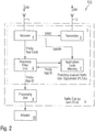
- FIG. 2 shows a block diagram of a possible exemplary embodiment of a proximity enabled traffic user equipment 1 used in a traffic control system TCS according to the first aspect of the present invention.
- the proximity enabled traffic user equipment, PETUE, 1 comprises in the shown embodiment a transmitter 2 which is adapted to broadcast within a broadcast signal range of the transmitter 2 a proximity service, ProSe, application code provided by a proximity service function PSF and associated with a proximity service application identifier.
- the proximity service application identifier is an identifier used by the proximity service direct discovery identifying application related information for the proximity service enabled user equipment. Each proximity service application identifier can be globally unique.
- the proximity service application code is associated with the proximity service application identifier and used in the discovery procedures.
- the geographic scope of a proximity service application identifier can be specific for a public land mobile network, PLMN, country-specific or even global.
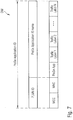
- Figure 7 shows a possible exemplary data structure of a proximity service application identifier included in a discovery message DM as used by the traffic control system TCS according to the first aspect of the present invention.
- the proximity service, ProSe, application identifier comprises a sequence of traffic labels TLs representing hierarchical traffic information levels.
- the proximity service application identifier further comprises a public land mobile network, PLMN, identifier corresponding to the public land mobile network PLMN that has assigned the proximity service application ID name consisting of the string of traffic labels TLs as illustrated in Fig. 7 .
- transmission resources TR in the time and/or frequency domain used for broadcasting the discovery message DM via the direct link are provided by the evolved node B of the E-UTRA air interface.
- resources in the time and frequency domain are assigned or dedicated to specific user equipment devices directly.
- the resources in the time and frequency domain are available to all admitted user equipment devices UEs in a resource pool.
- the enode B can configure or re-configure the proximity service application code lookup tables LUTs of participating proximity enabled traffic user equipment entities UEs as illustrated in Figure 4 .
- Another example of a proximity service application identifier sent by a transmitter of proximity enabled traffic user equipment 1 can be:
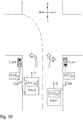
- Figure 9 shows as an example a vehicle driving at a speed V on a street and approaching a traffic sign indicating a speed limit of 70 kmh.
- the traffic sign has a proximity enabled traffic user equipment PETUEA broadcasting a discovery message DM to the proximity enabled traffic user equipment PETUEB of the vehicle.
- the proximity service application identifier name of the broadcasted discovery message DM can be for instance:
- FIG 11 shows as a further example a number of vehicles standing in front of a traffic light which is red.
- the proximity enabled traffic user equipment PETUEA of the traffic light informs the first car or vehicle VEH1 in the waiting queue about the traffic light, for instance that the current traffic light will last for another 60 s.
- the next vehicle VEH2 in the queue is not be equipped with a proximity enabled traffic user equipment so that the third vehicle VEH3 in the queue may be out of range of the transmitter of the proximity enabled traffic user equipment PETUEA of the traffic light.
- a proximity enabled traffic user equipment PETUE automatically forwards a received discovery message DM to other proximity enabled traffic user equipments PETUEs by broadcasting the received discovery message DM itself. In this way the proximity enabled traffic user equipment PETUEC of the last vehicle VEH3 standing in the queue can receive a discovery message DM in the given example of Figure 11 from the proximity enabled traffic user equipment PETUEB of the first vehicle VEH1 standing in the queue.
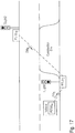
- the vehicle VEH comprises a proximity enabled traffic user equipment PETUE broadcasting periodically a discovery message DMA indicating that the vehicle is standing in front of the first traffic light to the proximity enabled traffic user equipment PETUEC of the first TLight1.
- the proximity enable traffic user equipment PETUEC further receives from the proximity enabled traffic user equipment PETUEB of the other traffic light TLight2 information via a discovery message DMB that no vehicle is approaching the other traffic light TLight2.
- DMB After interpreting both proximity service application identifier names of the received discovery messages DMA, DMB the processing unit possessing the received proximity service application identifier names sends a control signal to the first traffic light TLight1 so that it is automatically switched to green allowing the vehicle VEH to pass the construction site without waiting. Accordingly, it can be seen in Figure 17 that a vehicle VEH comprising a system including a proximity enabled traffic user equipment PETUE of the traffic control system TCS can provide advantages to the driver of the vehicle with such a user equipment device.
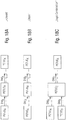
- Figures 18a, 18b, 18c show different scenarios for handling discovery messages DM by a proximity enabled traffic user equipment device.
- the received discovery message DM can be simply forwarded by the receiving proximity enabled traffic user equipment PETUE by broadcasting the received discovery message DM to other proximity enabled traffic user equipments PETUEs. This can be useful, for instance, in a situation as illustrated in Figure 11 , i.e. in a waiting queue in front of a traffic light.
- the broadcasted discovery message DM can trigger as cascade of discovery messages DMs with different proximity service application identifiers as illustrated in the examples of Figure 14 or Figure 15 .
- the traffic control system TCS can comprise a plurality of different traffic control units TCUs in particular infrastructure traffic control units of traffic infrastructure entities such as traffic signs or traffic lights.
- the traffic control unit 9 of the traffic control system TCS as illustrated in Figure 2 can also comprise a vehicle control unit of a vehicle such as a truck, car, bus a motorbike, a bicycle or train.
- Vehicles VEH can comprise any kinds of vehicles, in particular vehicles with specific purpose such as emergency vehicles or ambulance vehicles.
- the traffic control unit can also be formed by a mobile device control unit of a handheld mobile device in particular a mobile phone MP.
- the invention further relates to a method for providing a traffic control wherein traffic information is transported in a discovery message DM broadcasted by a proximity enabled traffic user equipment PETUE via a user equipment-user equipment link to another proximity enabled traffic user equipment.
- the discovery message DM includes a proximity service application identifier comprising a string or sequence of traffic information labels TLs representing hierarchical traffic information levels.
- the method can be implemented by a program comprising instructions performing the method steps.
- the transport of traffic information within proximity service application names of discovery messages DM is very robust and reliable. It can be implemented by devices without significant additional technical efforts.
- An existing traffic control system can be upgraded by implementing additional proximity enabled traffic user equipments.
Description
- The invention relates to a traffic control system and to a method for providing traffic control using a discovery message mechanism to transport traffic information.
- Traffic control relates to the control of traffic participants in particular to control vehicles in a traffic infrastructure of a predetermined area. Traffic control can involve directing vehicular or pedestrian traffic around a construction zone, accident or other road disruption, thus insuring the safety of emergency response teams, construction workers and public traffic participants. Further, traffic control is performed to avoid traffic congestion or traffic jams.
- Vehicles nowadays are equipped with a navigation system which supports the driver to avoid traffic jams. Navigation systems can suggest an alternative route based on a navigation map material and traffic announcements. A navigation system can use a GPS navigation device acquiring position data to locate the vehicle on a road stored in the unit map database. With the road database the navigation system can give directions to other locations along roads. However, conventional navigation systems have the disadvantage that they may rely on not updated or unreliable map data.
- Furthermore, vehicles are also equipped with driver assistance systems which support a driver of the vehicle to perform driving maneuvers such as parking maneuvers. These assistance systems can comprise vehicle cameras which are able to capture camera images of the vehicle's surrounding. The camera images of the vehicle's surrounding can be processed to extract traffic information. For example, a speed limit indicated by a traffic sign can be extracted from the captured camera image and used for driver assistance. However, this requires the availability of at least one vehicle camera in the vehicle and further requires sufficient computation resources for processing the camera images for traffic information extraction. A further disadvantage is that the captured camera images depend strongly on the environment. For example in a heavy fog environment it will not be possible to extract speed limit information indicated on a traffic sign.
- Document
WO 2014/074681 A1 discloses a system for Smart Traffic control using Peer to Peer (P2P) proximity communications. Infrastructure-based P2P communication uses 3GPP proximity services (ProSe). A User Equipment (UE) makes the initial determination of proximity and target discovery. Peer discovery may be a procedure to enable P2P proximity communications that may be used by a peer to find another peer before peer association. - Accordingly there is a need for an efficient and reliable traffic control system which overcomes the above-mentioned disadvantages.
- It is an object of the present invention to provide a reliable traffic control system which allows to control the traffic of traffic participants efficiently.
- This object is achieved by a traffic control system comprising the features of
claim 1. - The invention provides according to a first aspect a traffic control system, TCS, comprising at least one traffic control unit, TCU, equipped with a proximity enabled traffic user equipment, PETUE, adapted to control traffic of mobile entities,
wherein the proximity enabled traffic user equipment, PETUE, is configured to transmit traffic information by sending at least one discovery message, DM, directly via an user equipment to user equipment link to at least one other proximity enabled traffic user equipment, PETUE, of a mobile entity,
wherein the discovery message, DM, includes a proximity service application identifier comprising a sequence of traffic labels, TLs, representing hierarchical traffic information levels. - An advantage of the traffic control system, TCS, according to the first aspect of the present invention resides in that a discovery mechanism is used requiring no additional technical complexity and being robust against environmental influences. The use of a short range discovery message is resource efficient in particular with respect to resource utilization and energy efficiency. Further, by using a direct user equipment to user equipment link cellular data traffic is reduced, thus diminishing data traffic in the data network.
- In a further embodiment of the traffic control system, TCS, according to the first aspect of the present invention the proximity enabled traffic user equipment comprises a transmitter adapted to broadcast within a broadcast range of the transmitter a proximity service application code provided by a proximity service function and associated with the proximity service application identifier.
- In a further embodiment of the traffic control system according to the first aspect of the present invention the proximity enabled traffic user equipment comprises a receiver adapted to receive a broadcasted proximity service application code associated with the proximity service application identifier.
- In a further possible embodiment of the traffic control system according to the first aspect of the present invention the proximity enabled traffic user equipment comprises a discovery filter unit adapted to selectively match a received proximity service application code with proximity service application codes stored in a configurable lookup application code memory to retrieve the proximity service application identifier of the respective discovery message.
- In a possible embodiment of the traffic control system according to the first aspect of the present invention the lookup application code memory of the proximity enabled traffic user equipment is adapted to store a lookup table comprising application codes with associated proximity service application identifiers.
- In a further possible embodiment of the traffic control system according to the first aspect of the present invention the proximity service application identifier output by the discovery filter unit of said proximity enabled traffic user equipment is processed by a processor unit to generate control data in response to the traffic information transported in said proximity service application identifier included in said discovery message.
- In a further possible embodiment of the traffic control system according to the first aspect of the present invention the proximity service application identifier comprises a proximity service application identifier name composed of said sequence of traffic levels representing hierarchical traffic information levels and comprises a public land mobile network identifier of a public land mobile network.
- In a further possible embodiment of the traffic control system according to the first aspect of the present invention the proximity enabled traffic user equipment is in coverage of an evolved node B of an evolved UMTS terrestrial radio access, eUTRA, interface of a mobile network.
- In a further possible embodiment of the traffic control system according to the first aspect of the present invention transmission resources in the time and/or frequency domain used for transmission of the discovery message via said UE-UE link are provided by the evolved node B of the E-UTRA, interface of the mobile network.
- In a further possible embodiment of the traffic control system according to the first aspect of the present invention the lookup table stored in the lookup application code memory of the proximity enabled traffic user equipment is configured and updated by the evolved node B covering said proximity enabled traffic user equipment.
- In a further possible embodiment of the traffic control system according to the first aspect of the present invention the broadcast range and/or broadcast signal strength of the transmitter within the proximity service enabled traffic user equipment is adjustable.
- In a further possible embodiment of the traffic control system according to the first aspect of the present invention the broadcast range and/or broadcast signal strength of the transmitter of the proximity service enabled traffic user equipment is adjusted automatically depending on the proximity service application identifier of the broadcasted discovery message and/or depending on a movement speed of the proximity service enabled traffic user equipment.
- In a further possible embodiment of the traffic control system according to the first aspect of the present invention the sequence of traffic labels representing the hierarchical traffic information levels within the proximity service application identifier of the discovery message sent by a proximity enabled traffic user equipment comprises traffic direction information indicating a current and/or future moving direction of a proximity enabled traffic user equipment of a mobile entity.
- In a further possible embodiment of the traffic control system according to the first aspect of the present invention the sequence of traffic labels representing hierarchical traffic information levels within the proximity service application identifier of the discovery message comprises validity information indicating a validity time, a validity range and/or a validity scope of the traffic information transported in the proximity service application identifier of the discovery message.
- The invention further provides according to a second aspect a proximity enabled traffic user equipment comprising the features of
claim 15. - The invention provides according to the second aspect a proximity enabled traffic user equipment, PETUE, for a traffic control system, TCS, according to the first aspect of the present invention, said proximity enabled traffic user equipment, PETUE, comprising
a transmitter adapted to broadcast within a broadcast range of the transmitter a proximity service application code provided by a proximity service function and associated with the proximity service application identifier of a discovery message, DM, and
a receiver adapted to receive a broadcasted proximity service application code associated with a proximity service application identifier of a discovery message, DM. - In a possible embodiment of the proximity enabled traffic user equipment according to the second aspect of the present invention said proximity enabled traffic user equipment further comprises a discovery filer unit adapted for selectively matching a received proximity service application code with proximity service application codes stored in a configurable lookup application code memory to retrieve the proximity service application identifier of the received discovery message.
- The invention further provides according to a third aspect a traffic control unit, TCU, comprising the features of claim 17.
- The invention provides according to the third aspect a traffic control unit, TCU, for a traffic control system, TCS, according to the first aspect of the present invention wherein the traffic control unit, TCU, comprises a proximity enabled traffic user equipment, PETUE, according to the second aspect of the present invention and further comprises a processing unit adapted to process the proximity service application identifier output by the discovery filter to generate control data adapted to control an actuator.
- In a possible embodiment of the traffic control unit according to the third aspect of the present invention the traffic control unit comprises an infrastructure control unit of an infrastructure entity.
- The infrastructure entity can be in a possible embodiment a traffic sign or a traffic light.
- In a further possible embodiment of the traffic control unit according to the third aspect of the present invention the traffic control unit comprises a vehicle control unit of a vehicle.
- The vehicle is in a preferred embodiment a land vehicle comprising a car, truck or bus, in particular an emergency vehicle. The vehicle can also comprise a train.
- In a further possible embodiment of the traffic control unit according to the third aspect of the present invention the traffic control unit is a mobile device control unit of a handheld mobile device in particular of a mobile phone.
- The invention further provides according to a fourth aspect a navigation system for a vehicle controlled by a traffic control system, TCS, according to the first aspect of the present invention, said vehicle comprising a proximity enabled traffic user equipment, PETUE, according to the second aspect of the present invention,
wherein control data is generated by a processing unit of said navigation system in response to the proximity service application identifier provided by the discovery filter unit of the proximity enabled traffic user equipment. - The invention further provides according to a fifth aspect a method comprising the features of claim 20.
- The invention provides according to the fifth aspect a method for providing traffic control, wherein traffic information is transported in a discovery message, DM, broadcasted by a proximity enabled traffic user equipment, PETUE, via a user equipment to user equipment link to another proximity enabled traffic user equipment, PETUE, wherein said discovery message, DM, includes a proximity service application identifier comprising a sequence of traffic labels, TLs, representing hierarchical traffic information levels.
- In a possible embodiment of the method according to the fifth aspect of the present invention a broadcast range and/or a signal strength of the broadcasted discovery message, DM, is adjusted automatically depending on the proximity service application identifier of the broadcasted discovery message, DM, and/or depending on a movement speed of the proximity enabled traffic user equipment, PETUE.
- In a further possible embodiment of the method according to the fifth aspect of the present invention the sequence of traffic labels, TLs, representing hierarchical traffic information levels within the proximity service application identifier of the discovery message, DM, sent by the proximity enabled traffic user equipment, PETUE, comprises traffic direction information indicating a current and/or a future moving direction of a proximity enabled traffic user equipment, PETUE, within a mobile entity.
- In a further possible embodiment of the method according to the fifth aspect of the present invention the sequence of traffic labels, TLs, representing hierarchical traffic information levels within the proximity service application identifier of the discovery message, DM, sent by a proximity enabled traffic user equipment, PETUE, comprises validity information indicating a validity time, a validity range and/or a validity scope of the traffic information transported in the proximity service application identifier of the discovery message, DM.
- In a further possible embodiment of the method according to the fifth aspect of the present invention the discovery message, DM, is broadcasted by the proximity enabled traffic user equipment, PETUE, periodically with a predetermined or adjusted broadcast repetition rate, RR.
- In a further possible embodiment of the method according to the fifth aspect of the present invention the broadcast repetition rate, RR, is adjusted depending on the proximity service application identifier of the broadcasted discovery message, DM, and/or depending on a moving speed of the proximity enabled traffic user equipment, PETUE.
- In the following possible embodiments of the different aspects of the present invention are described with reference to the enclosed figures in more detail.
- Fig. 1
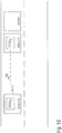
- shows a diagram for a possible exemplary network architecture of a network used by the traffic control system and traffic control method according to the present invention;
- Fig. 2
- shows a block diagram of an exemplary embodiment of proximity enabled traffic user equipment within a traffic control unit according to an aspect of the present invention;
- Fig. 3
- shows a table for illustrating a possible exemplary embodiment in a lookup table withinan application code memory of a proximity enabled traffic user equipment according to an aspect of the present invention;
- Fig. 4
- shows a diagram for illustrating an operation traffic control system and traffic control method according to an aspect of the present invention;
- Fig. 5A-5E
- illustrate a possible coverage status of proximity enabled traffic user equipment devices within a traffic control system according to an aspect of the present invention;
- Fig. 6
- shows a diagram to illustrating a direct user equipment to user equipment link as employed by the traffic control system and traffic control method according to the present invention,
- Fig. 7
- shows an exemplary data structure of a direct message as employed by the traffic control system and traffic control method according to the present invention;
- Fig. 8
- shows a schematic diagram illustrating possible traffic labels within a discovery message as illustrated in
Figure 7 ; - Fig. 9-17
- illustrate exemplary use cases for a traffic control system and traffic control method according to the present invention;
- Fig. 18 A,B,C
- illustrate possible operation modes of a traffic control system and a traffic control method according to the present invention;
- Fig. 19
- shows a time diagram for illustrating an exemplary embodiment of a traffic control system and traffic control method according to the present invention;
- Fig. 20
- shows a schematic diagram for illustrating traffic direction information data as used in a possible specific embodiment of the traffic control system and traffic control method according to the present invention.
- In a possible embodiment of the traffic control system, TCS, according to the first aspect of the present invention the traffic control system, TCS, employs a proximity service of a 3GPP network.
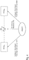
Figure 1 illustrates a reference architecture by a 3GPP system employed by the traffic control system TCS according to the first aspect of the present invention. Proximity services (ProSe) are formed by services that can be provided by such a 3GPP system based on user equipment devices UE being in proximity to each other. The proximity service function, PSF, of the system illustrated inFigure 1 is a logical function that can be used for method related actions required for a proximity service. Direct discovery provides the capability of detecting other user equipment devices by a user equipment device UE. By using direct discovery a user equipment UE can search for nearby user equipment devices autonomously. User equipment devices, UE, participating in the device discovery process can transmit periodically discovery messages, DM. In proximity service direct discovery a user equipment UE in the vicinity of another user equipment UE is detected and identified using E-UTRA direct radio signals. E-UTRA is the air interface of a 3GPP long term evolution, LTE, mobile network using the reference architecture as illustrated inFigure 1 . E-UTRA is the air interface for evolved UMTS terretial radio access. E-UTRA stands for the combination of E-UTRA, the user equipment devices UEs and Enode Bs. In a discovery mechanism the user equipment EU can broadcast its presence to other user equipment devices UEs. The traffic control system TCS according to the first aspect of the present invention comprises at least one traffic control unit TCU equipped with a proximity enabled traffic user equipment, PETUE, as illustrated in the block diagram ofFigure 2 . The proximity enabled traffic user equipment, PETUE, is adapted to control traffic or movement of at least one mobile entity such as a vehicle equipped with another proximity enabled traffic user equipment PETUE. The proximity enabled traffic user equipment PETUE of the traffic control unit TCU is configured to transmit traffic information by sending at least one discovery message DM directly via a link to the other proximity enabled traffic user equipment PETUE. The discovery message DM is broadcasted by the proximity enabled traffic user equipment PETUE of the traffic control TCU unit and includes a proximity service, ProSe, application identifier comprising a string of traffic labels, TLs, representing hierarchical traffic information levels. The broadcasting proximity enabled traffic user equipment broadcasts direct discovery message DM in a preferred embodiment periodically as also illustrated inFigure 19 . In a preferred embodiment the proximity enabled traffic user equipment PETUE of the traffic control system TCS according to the first aspect of the present invention is in coverage of an evolved node B of an evolved UMTS terrestial radio access, E-UTRA, air interface of a mobile network. The transmission ressources in the time domain and the frequency domain used for transmission of the discovery message DM in the user equipment to user equipment link are provided by the evolved node B of the E-UTRA air interface within the mobile network as illustrated inFigure 4 . In a possible embodiment the broadcast range BR and/or the broadcast signal strength SS of the broadcasted direct discovery message DM is adjustable. In the traffic control system TCS according to the first aspect of the present invention the discovery message DM is broadcasted unidirectional from a source proximity enabled traffic user equipment S-PETUE to other proximity enabled traffic user equipment devices within the broadcast range BR of this source proximity enabled traffic user equipment device. The source proximity enabled traffic user equipment can be for example a proximity enabled traffic user equipment PETUE of a traffic infrastructure control device such as a traffic sign or a traffic light. A receiving proximity enabled traffic user equipment device receiving the broadcasted discovery message DM can be for instance a proximity enabled traffic user equipment of a vehicle VEH moving in the vicinity of the traffic infrastructure device. In the traffic control system TCS according to the first aspect of the present invention the information transport within the broadcasted discovery message DM is unidirectional and there is no bidirectional communication between both proximity enabled traffic user equipment devices PETUE. This diminishes the complexity of the traffic control system TCS and increases its robustness against external influences. Consequently, the traffic control system TCS according to the present invention is reliable and provides a comparatively low additional technical complexity. The proximity enabled user equipment UE is a user equipment UE that supports proximity service requirements and associated procedures. A proximity service enabled user equipment can comprise a non public safety user equipment or a public safety user equipment. By use of the proximity service direct discovery the proximity service enabled traffic user equipment PETUE discovers other proximity service enabled traffic user equipments PETUEs in its vicinity by using capabilities of user equipment devices within the E-UTRA air interface of the LTE network. -
Figure 2 shows a block diagram of a possible exemplary embodiment of a proximity enabledtraffic user equipment 1 used in a traffic control system TCS according to the first aspect of the present invention. The proximity enabled traffic user equipment, PETUE, 1 comprises in the shown embodiment atransmitter 2 which is adapted to broadcast within a broadcast signal range of the transmitter 2 a proximity service, ProSe, application code provided by a proximity service function PSF and associated with a proximity service application identifier. The proximity service application identifier is an identifier used by the proximity service direct discovery identifying application related information for the proximity service enabled user equipment. Each proximity service application identifier can be globally unique. The proximity service application code is associated with the proximity service application identifier and used in the discovery procedures. The geographic scope of a proximity service application identifier can be specific for a public land mobile network, PLMN, country-specific or even global.Figure 7 shows a possible exemplary data structure of a proximity service application identifier included in a discovery message DM as used by the traffic control system TCS according to the first aspect of the present invention. The proximity service, ProSe, application identifier comprises a sequence of traffic labels TLs representing hierarchical traffic information levels. The proximity service application identifier further comprises a public land mobile network, PLMN, identifier corresponding to the public land mobile network PLMN that has assigned the proximity service application ID name consisting of the string of traffic labels TLs as illustrated inFig. 7 . The public land mobile network ID can comprise in a possible embodiment a mobile country code MCC and a mobile network code MMC as shown inFigure 7 . To each proximity service, ProSe, application identifier a corresponding proximity service application code is associated which can be obtained in a possible embodiment from a HPLMN proximity service function. The proximity service application code is contained in the discovery message DM that is transmitted over the radio interface by a proximity enabled traffic user equipment PETUE engaged in the proximity service direct discovery procedure to other monitoring proximity enabled traffic user equipment devices PETUEs. The proximity service application code is a number which corresponds at a certain time to a corresponding proximity service application identifier. - The proximity enabled
traffic user equipment 1 illustrated inFigure 2 can transmit a discovery message DM with an adjustable signal strength by means of a transmittingantenna 3 via a direct link to at least one other proximity enabled traffic user equipment PETUE in its vicinity. The proximity enabledtraffic user equipment 1 further comprises areceiver 4 being connected to a receiving antenna 5, wherein thereceiver 4 is adapted to receive a broadcasted proximity service application code associated with a proximity service application identifier. The proximity service application code is supplied by thereceiver 4 to adiscovery filter unit 6 of the proximity enabledtraffic user equipment 1 as shown inFigure 2 . Thediscovery filter unit 6 has access to anapplication code memory 7 of the proximity enabledtraffic user equipment 1. Thediscovery filter unit 6 is adapted to selectively match a received proximity service application code with proximity service application codes stored in the configurable lookupapplication code memory 7 to retrieve the proximity service application identifier of the received discovery message DM.Figure 3 illustrates schematically a lookup table LUT stored in theapplication code memory 7 of the proximity enabledtraffic user equipment 1. The received proximity service application code is supplied by thediscovery filter unit 6 to retrieve the associated proximity service application identifier. - The retrieved prosecution service application identifier is then output by the
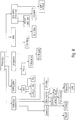
discovery filter unit 6 to aprocessing unit 8 of a traffic control unit (TCU) 9 comprising the proximity enabledtraffic user equipment 1. Thetraffic control unit 9 can be in a possible embodiment a control unit of an infrastructure control device such as a traffic light. In a possible embodiment theprocessing unit 8 generates control data or control signals in response to the traffic information data transported in the proximity service application identifier included in the discovery message DM. The control data can be used in a possible embodiment to control anactuator 10 connected to thetraffic control unit 9. Theactuator 10 can be for example a traffic light or barrier controlled by thetraffic control unit 9. The lookup table LUT stored in the lookupapplication code memory 7 of the proximity enabledtraffic user equipment 1 can be configurable or programmable and can be updated by the evolved node B covering the respective proximity enabledtraffic user equipment 1. Thereceiver 4 further can extract a synchronization signal and supply it to thetransmitter 2 as shown inFigure 2 . In a possible embodiment of theapplication code memory 7 can be a replaceable application code memory formed by memory card or the like. By replacing the application code memory 7 a reconfiguration of the proximity enabledtraffic user equipment 1 can be achieved. The proximity service application identifier stored in theapplication code memory 7 as illustrated inFigure 3 comprises a proximity service application identifier name and optionally a public land mobile network, PLMN, identifier of a public land mobile network PLMN as illustrated inFigure 7 . As shown inFigure 4 transmission resources TR in the time and/or frequency domain used for broadcasting the discovery message DM via the direct link are provided by the evolved node B of the E-UTRA air interface. In a possible embodiment resources in the time and frequency domain are assigned or dedicated to specific user equipment devices directly. Alternatively, the resources in the time and frequency domain are available to all admitted user equipment devices UEs in a resource pool. Further, the enode B can configure or re-configure the proximity service application code lookup tables LUTs of participating proximity enabled traffic user equipment entities UEs as illustrated inFigure 4 . - The proximity enabled traffic user equipment device PETUE is in coverage of an evolved enode B of an evolved UMTS terrestial radio access air interface. Different scenarios are illustrated in
Figures 5a, 5b, 5c and 5d . As can be seen inFigure 5a both proximity enabled traffic user equipment devices can be in coverage of the same evolved node B of the air interface. It is also possible that both proximity enabled traffic user equipment devices PETUEs are covered by two different evolved node B of the same public land mobile network PLMN as illustrated inFigure 5b . It is also possible that both proximity enabled traffic user equipment devices PETUEs in are in coverage of two different evolved node Bs of two different public land mobile networks PLMNA, PLMNB as shown inFigures 5c, 5d and 5e . -
Figure 6 shows schematically the user equipment-user equipment direct link between two proximity enabled traffic user equipment devices for transmitting of the discovery message DM. -
Figure 7 shows a possible data structure of a discovery message DM employed by the traffic control system TCS according to the first aspect of the present invention. As can be seen the proximity service, ProSe, application ID comprises a public land mobile network ID of a public land mobile network PLMN as well as a proximity service application identifier name consisting of a sequence of traffic labels TLs carrying traffic information attributes. The proximity service application identifier is composed of a number N of traffic information labels TLs representing hierarchical traffic information levels. The number of traffic labels TLs can vary. The public land mobile network ID is optional and can comprise a mobile country code MCC and a mobile network code MNC as shown inFigure 7 . -
Figure 8 shows schematically the possible composition of a proximity service application identifier name for different exemplary use cases. The proximity service application identifier name can for instance be a sequence of the following traffic labels TLs: - ProSeApp.Traffic Sign.Speed Limit.70kmh
- These traffic labels TLs can be included in a discovery message DM sent by a
traffic control unit 9 of a traffic sign along a road indicating that the speed limit of a vehicle travelling on the road is 70 kmh. - Another example of a proximity service application identifier sent by a transmitter of proximity enabled
traffic user equipment 1 can be: - ProSeApp.Traffic Light.Red>25sec.
- This proximity service application identifier can be sent within a discovery message DM by the
transmitter 2 of a proximity enabled trafficuser equipment device 1 within atraffic control unit 9 of a traffic light of a road crossing indicating that the respective traffic light is currently set to red and will remain red for more than 25 s. - Another exemplary proximity service application identifier is: ProSeApp.Emergency.Ambulance.
- A discovery message DM having included such a proximity service application identifier can be sent by a
transmitter 2 of a proximity enabled trafficuser equipment device 1 provided within an ambulance or emergency vehicle. - The hierarchical structure of the traffic information labels TLs provides a predetermined variety of different proximity service application identifiers. In a possible embodiment the string of traffic labels TLs representing hierarchical traffic information levels within the proximity service application identifier of the discovery message DM sent by the proximity enabled
traffic user equipment 1 can comprise validity information indicating a validity time, a validity range and/or a validity scope of the traffic information carried in the proximity service application identifier of the discovery message DM. For instance, the following proximity service application identifier name: ProSeApp.Speedlimit.70kmh.Range.2000m indicates that the 70 kmh speed limit of the traffic sign is valid only for the next 2000 m along the road. - Further the validity information may indicate a validity scope of the traffic information. For example, the following proximity service application identifier name: ProSeApp.Speedlimit.70kmh.ValidForLorries indicates that the transported traffic information is only valid for lorries or trucks but not for other vehicles such as cars.
- The validity information can also indicate a validity time.
- For Example, the proximity service application identifier name: ProSeApp.TrafficLight.Red.Validity.15s indicates that the traffic light is red for the next 15s.
- The
discovery filter unit 6 within the proximity enabledtraffic user equipment 1 is adapted to selectively match or retrieve the proximity service application identifier of the received discovery message DM. Adiscovery filter unit 6 without a proximity service application mask can be used for identification of a full match of the service indicated in the proximity service application code. Adiscovery filter unit 6 with a proximity service application mask allows a partial matching of any parts of the proximity service application code that as are contained in the proximity service application mask. By processing the proximity service application identifier a partial matching can be achieved to control anactuator 10. For instance each proximity service application identifier name comprising the traffic information labels TLs ProSeApp.TrafficLight can be used to inform a driver of a vehicle by means of an optical or acustical signal that the vehicle is approaching a traffic light so that the driver becomes more observant to the coming traffic light. The proximity enabled traffic user equipment, PETUE, 1 can also be implemented in a vehicle such as an ambulance vehicle. For example, the proximity enabledtraffic user equipment 1 of an ambulance vehicle can transmit a discovery message DM including a proximity service application identifier name as follows: ProSeApp.EmergencyTraffic indicating that the proximity enabled traffic user equipment, PETUE, 1 is implemented in an ambulance vehicle performing an emergency transport of a person. If such a discovery message DM is received by another proximity enabledtraffic user equipment 1 of a traffic light of a road crossing the traffic light is switched automatically to green so that the ambulance vehicle can pass the road crossing. - In the following examples and use cases are illustrated with reference to the enclosed figures for illustrating the operation of a traffic control system TCS according to the first aspect of the present invention.
-
Figure 9 shows as an example a vehicle driving at a speed V on a street and approaching a traffic sign indicating a speed limit of 70 kmh. the traffic sign has a proximity enabled traffic user equipment PETUEA broadcasting a discovery message DM to the proximity enabled traffic user equipment PETUEB of the vehicle. The proximity service application identifier name of the broadcasted discovery message DM can be for instance: - ProSeApp.TrafficSign.Speedlimit.70kmh. When receiving the proximity service application code the
discovery filter unit 6 of the receiving proximity enabled traffic user equipment PETUEB can retrieve the corresponding proximity service application identifier from itsapplication code memory 7 wherein the retrieved proximity service application identifier is processed by theprocessing unit 8. Theprocessing unit 8 can generate control data or control signals in response to the identified proximity service, ProSe, application identifier name. In the given example ofFigure 9 the speed limit of 70 kmh may be displayed to the driver on a display and/or an accoustial or optical announcement by the driver assistance system of the vehicle can be made to the driver so that he becomes aware of the indicated traffic speed limit. In a possible embodiment of the traffic control system TCS the vehicle can be configured to provide an operation mode where the vehicle is automatically slowed down by anactuator 10 to the required maximum speed limit of 70 kmh. -
Figure 10 shows a further example use case where a vehicle B is approaching with a specific speed V a vehicle A standing on a road at the end of a traffic congestion. As soon as the vehicle A analyses from a movement history that it is now standing and forms the end of a traffic congestion or traffic jam its starts to send periodically a discovery message DM that will be received by the proximity enabled traffic user equipment PETUEB of the approaching vehicle B. The proximity service application identifier name of the discovery message can be for example: ProSeApp.Vehicle.traffic congestion.standing. - When receiving the discovey message DM a driver of the approaching vehicle B can receive a warning that his vehicle B is approaching a standing vehicle A forming the end of a traffic jam. The driver of the vehicle B will slow down his vehicle B so that it comes to a stand behind vehicle A on the road forming now a new end of the traffic jam. In a possible embodiment after realizing that the vehicle B forms the new end of the traffic jam the proximity enabled traffic user equipment PETUEB of the vehicle B can be triggered to broadcast now itself a discovery message DM warning other vehicles following vehicle B on the road.
-
Figure 11 shows as a further example a number of vehicles standing in front of a traffic light which is red. The proximity enabled traffic user equipment PETUEA of the traffic light informs the first car or vehicle VEH1 in the waiting queue about the traffic light, for instance that the current traffic light will last for another 60 s. The next vehicle VEH2 in the queue is not be equipped with a proximity enabled traffic user equipment so that the third vehicle VEH3 in the queue may be out of range of the transmitter of the proximity enabled traffic user equipment PETUEA of the traffic light. According to a possible embodiment a proximity enabled traffic user equipment PETUE automatically forwards a received discovery message DM to other proximity enabled traffic user equipments PETUEs by broadcasting the received discovery message DM itself. In this way the proximity enabled traffic user equipment PETUEC of the last vehicle VEH3 standing in the queue can receive a discovery message DM in the given example ofFigure 11 from the proximity enabled traffic user equipment PETUEB of the first vehicle VEH1 standing in the queue. -
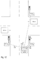
Figure 12 shows as further use case an emergency vehicle or ambulance approaching a road crossing. The proximity enabled traffic user equipment PETUEA of the ambulance broadcasts a discovery message DM to proximity enabled traffic user equipments PETUEs of the different traffic lights standing at the road crossing so that they are switched accordingly. In the given example the traffic lights are switched such that the ambulance vehicle can pass the road crossing immediately, whereas other vehicles VEH approaching the same road crossing have to wait until the ambulance has passed the road crossing. -
Figure 13 shows as a further use case a pedestrian P having a mobile phone MP wishing to cross a street having a pedestrian traffic light PTL. For instance, the person P wanting to cross the street may be a blind person having a mobile phone MP with an integrated proximity enabled traffic user equipment PETUE. In a possible embodiment the person P may activate by means of a mobile phone App the proximity enabled traffic user equipment PETUEB to receive discovery messages DM from pedestrian traffic lights PTLs. In the shown example the proximity enabled traffic user equipment A of the pedestrian traffic light PTL is transmitting periodically discovery messages DMs indicating the traffic state of the pedestrian traffic light PTL. In the shown embodiment the pedestrian traffic light PTL is switched to green so that the proximity enabled traffic user equipment PETUEB of the mobile phone MP handheld by the blind person P can receive a proximity service application identifier name as follows: - ProSeApp.TrafficLight.PedestrianTrafficLight.Green.30s indicating that the pedestrian traffic light PTL is green and will remain green for 30 seconds. The
processing unit 8 of the mobile phone MP can interpret the retrieved proximity service application identifier and inform the blind person P by a loud speaker of the mobile phone MP that he can pass the pedestrian traffic light PTL in the next 30 seconds. In the given example ofFigure 13 the proximity enabled traffic user equipment PETUEA can also be coupled to a vehicle traffic light VTL. The proximity enabled traffic user equipment PETUEA can send via another link a further discovery message DMVTL to another proximity enabled traffic user equipment PETUEB' of a vehicle VEH in front of the vehicle traffic light VTL which is switched to red as illustrated inFigure 13 . -
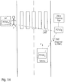
Figure 14 shows a further example illustrating a cascade of discovery messages DM1, DM2 via a chain of proximity enabled traffic user equipment devices PETUEs. In the shown example a person P having a mobile phone MP is approaching a zebra crossing having a zebra crossing traffic sign equipped with a proximity enabled traffic user equipment PETUEB. The mobile phone MP of the person P is equipped with a proximity enabled traffic user equipment PETUEA broadcasting a discovery message DM periodically indicating that the pedestrian P is approaching. As soon as the proximity enabled traffic user equipment PETUEB of the zebra crossing traffic sign receives the discovery message DM1 from the mobile phone MP of the person P another discovery message DM2 is triggered and broadcasted which can be received by a proximity enabled traffic user equipment PETUEC of a vehicle VEH moving towards the zebra crossing as illustrated inFigure 14 . In this way the driver of the vehicle VEH is informed that he is not only approaching a zebra crossing but also that a person P is currently crossing the zebra crossing. -
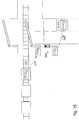
Figure 15 shows a further example for a triggered chain of discovery messages DM when a train is approaching a crossing street. The train comprises a proximity enabled traffic user equipment PETUEA broadcasting periodically discovery messages DM1, which can be received by a proximity enabled traffic user equipment PETUEB of a barrier. As soon as the barrier receives the broadcasted first discovery message DM1 from the train it is closed automatically and sends a triggered second discovery message DM2 to the proximity enabled traffic user equipment PETUEC of a traffic light in front of the barrier being switched to red. The proximity enabled traffic user equipment PETUEC of the traffic light can in turn generate a third discovery message DM3 broadcasted and received by the proximity enabled traffic user equipment PETUED of an approaching vehicle VEH informing the driver of the vehicle about the red traffic light and the closed barrier. -
Figure 16 shows a further possible embodiment of a traffic control system TCS according to the first aspect of the present invention. In a possible embodiment the string of traffic labels TLs representing hierarchical traffic information levels within the proximity service application identifier of the discovery message DM sent by a proximity enabled traffic user equipment PETUE comprises traffic direction information indicating a current and/or a future moving direction of a proximity enabled traffic user equipment PETUE. In the shown example two vehicles on the same street are approaching a road crossing with two traffic lights, i.e. a traffic light TLight1 and traffic light TLight2 wherein the first traffic light TLight1 is provided for the right lane of the street and the other traffic light TLight2 is provided for the left lane of the street. Both traffic lights comprise a proximity enabled traffic user equipment PETUEA1 and PETUEA2 wherein a first discovery message DM1 is broadcasted by the first proximity enabled traffic user equipment PETUEA1 of the first traffic light to a receiving proximity enabled traffic user equipment PETUEB1 of the first vehicle VEH1 and wherein a second proximity enabled traffic user equipment PETUEA2 of the second traffic light is sending a discovery message DM2 to the receiving proximity enabled traffic user equipment PETUEB2 of the second vehicle VEH2 driving on the left lane. In the given example the first traffic light TLight1 is switched to green and the second traffic light TLight2 for the left turning lane is switched to red. Accordingly, the first discovery message DM1 transports a proximity service application identifier name indicating the traffic light is green (ProSeApp.TrafficLight.Green) and the second discovery message DM2 transports a proximity service application identifier name indicating that the traffic light is red (ProSeApp.TrafficLight.Red). Since the broadcasting ranges of the two traffic lights may overlap the two vehicles VEH1, VEH2 may receive both discovery messages DM1, DM2. To avoid conflicts and misinterpretations the traffic label TL string comprises in a preferred embodiment also traffic direction information indicating for instance a current and/or a future direction. For example,Figure 16 shows two vehicles VEH1, VEH2 driving in north direction (N), wherein the current direction as well as the intended future direction of the first vehicle VEH1 is north (N) while the current direction of the second vehicle VEH2 is north (N) but the future intended direction of the vehicle VEH2 is west (W). Accordingly, the discovery method DM2 broadcasted by the proximity enabled traffic user equipment PETUEA2 of the second traffic light TLight2 can indicate that it is only valid for vehicles with the current direction north (N) and the future direction west (W). For example, the discovery message DM2 of the second traffic light TLight2 can comprise a proximity service application identifier name as follows: ProSeApp.TrafficLight.red.10 seconds.current direction N.future direction W. In a possible embodiment of the traffic control system TCS according to the first aspect of the present invention the traffic direction information can comprise eight different directions (N, W, S, E, NW, SW, NE, SE) as illustrated inFigure 20 . -
Figure 17 shows a further exemplary use case of a vehicle VEH comprising a proximity enabled traffic user equipment PETUEA approaching a traffic light setup temporarily at a construction site of a road. The construction site of the road is narrowed to a single lane so that the vehicle VEH can only pass if the setup construction site traffic light is green. At both ends of the construction site at traffic light is setup each having a proximity enabled traffic user equipment PETUE. In the given example the vehicle VEH is approaching the construction site at one end whereas no vehicle is approaching the construction site at the other end. The vehicle VEH comprises a proximity enabled traffic user equipment PETUE broadcasting periodically a discovery message DMA indicating that the vehicle is standing in front of the first traffic light to the proximity enabled traffic user equipment PETUEC of the first TLight1. The proximity enable traffic user equipment PETUEC further receives from the proximity enabled traffic user equipment PETUEB of the other traffic light TLight2 information via a discovery message DMB that no vehicle is approaching the other traffic light TLight2. After interpreting both proximity service application identifier names of the received discovery messages DMA, DMB the processing unit possessing the received proximity service application identifier names sends a control signal to the first traffic light TLight1 so that it is automatically switched to green allowing the vehicle VEH to pass the construction site without waiting. Accordingly, it can be seen inFigure 17 that a vehicle VEH comprising a system including a proximity enabled traffic user equipment PETUE of the traffic control system TCS can provide advantages to the driver of the vehicle with such a user equipment device. -
Figures 18a, 18b, 18c show different scenarios for handling discovery messages DM by a proximity enabled traffic user equipment device. As can be seen inFigure 18a the received discovery message DM can be simply forwarded by the receiving proximity enabled traffic user equipment PETUE by broadcasting the received discovery message DM to other proximity enabled traffic user equipments PETUEs. This can be useful, for instance, in a situation as illustrated inFigure 11 , i.e. in a waiting queue in front of a traffic light. - Further, as illustrated in
Figure 18b the broadcasted discovery message DM can trigger as cascade of discovery messages DMs with different proximity service application identifiers as illustrated in the examples ofFigure 14 orFigure 15 . - Moreover, as shown in
Figure 18 discovery messages DMs received by a proximity traffic user equipment PETUE from different source proximity enabled traffic user equipments to can evaluated or logically combined to trigger a specific discovery message DM with a specific proximity service application identifier name or to generate a specific control signal as illustrated in the example ofFigure 17 . - In a possible embodiment the discovery message DM is broadcasted by the proximity enabled traffic user equipment PETUE periodically as illustrated in
Figure 19 . The broadcast period T can be in a possible embodiment be fixed or pre-configured. In a further possible embodiment the broadcast period T corresponding to a broadcast repetition rate RR (RR = 1:T) can be adjusted. In a possible embodiment the broadcast repetition rate RR of the discovery message DM is adjusted depending from the application identifier of the broadcasted discovery message. For instance, a discoverage message DM with high importance or priority can be broadcasted with a higher broadcast repetition rate RR than a proximity service application identifier of less importance. Further, the broadcast repetition rate RR can be adjusted in a further embodiment automatically depending on the moving speed V of the proximity enabled traffic user equipment PETUE broadcasting the respective discovery message DM. The vehicle VEH such as a train approaching barrier with a high speed VH can broadcast the discovery message DM in a preferred embodiment with a higher broadcast repetition rate RR than when approaching the barrier with a very low speed VL. Also the signal strength SS and/or the broadcast range BR of the broadcasted discovery message DM can be adjusted in a possible embodiment depending on the proximity service application identifier name transported in the discovery message DM and/or depending on the moving speed V of the proximity enabled traffic user equipment broadcasting PETUE broadcasting the discovery message DM. - The traffic control system TCS according to the first aspect of the present invention can comprise a plurality of different traffic control units TCUs in particular infrastructure traffic control units of traffic infrastructure entities such as traffic signs or traffic lights. The
traffic control unit 9 of the traffic control system TCS as illustrated inFigure 2 can also comprise a vehicle control unit of a vehicle such as a truck, car, bus a motorbike, a bicycle or train. Vehicles VEH can comprise any kinds of vehicles, in particular vehicles with specific purpose such as emergency vehicles or ambulance vehicles. The traffic control unit can also be formed by a mobile device control unit of a handheld mobile device in particular a mobile phone MP. - The invention further relates to a method for providing a traffic control wherein traffic information is transported in a discovery message DM broadcasted by a proximity enabled traffic user equipment PETUE via a user equipment-user equipment link to another proximity enabled traffic user equipment. The discovery message DM includes a proximity service application identifier comprising a string or sequence of traffic information labels TLs representing hierarchical traffic information levels. The method can be implemented by a program comprising instructions performing the method steps. The transport of traffic information within proximity service application names of discovery messages DM is very robust and reliable. It can be implemented by devices without significant additional technical efforts. An existing traffic control system can be upgraded by implementing additional proximity enabled traffic user equipments. Proximity enabled traffic user equipments PETUEs provided within vehicles VEH such as cars can be supplied with energy by a battery of the vehicle VEH. Proximity enabled traffic user equipments PETUE located at a traffic control unit of a traffic infrastructure entity such as a traffic light can also be supplied with energy from the same energy source feeding the traffic light. Isolated traffic signs along a road equipped with a proximity enabled traffic user equipment PETUE can be supplied with electric power of a local battery or generated by a photovoltaic panel since the broadcasting of discovery messages DMs consumes only little electrical power. The proximity enabled traffic user equipment PETUE can provide proximity service, ProSe, application identifier names which can be evaluated by an existing navigation system of a vehicle VEH to increase its functionality. The traffic control system TCS can be used to provide increased security and/or efficiency in a variety of traffic situations as illustrated in the above exemplary embodiments and can be configured for active road safety applications such as collision warning or road work warning. The system and method according to the present invention can be implemented for safety applications vehicle to vehicle, vehicle to pedestrian and/or vehicle to infrastructure.
-
- PETUE
- Proximity Enable Traffic User Equipment
- TCS
- Traffic Control Systems
- TCU
- Traffic Control Unit
- VEH
- Vehicle
- TL
- Traffic Label
- DM
- Discovery Message
- LUT
- Look up Table
- 1
- Proximity Enable Traffic User Equipment
- 2
- Transmitter
- 3
- Transmitter antenna
- 4
- Receiver
- 5
- Receiver antenna
- 6
- Discovery filter unit
- 7
- Application code memory
- 8
- Processing Unit
- 9
- Traffic control unit
- 10
- Actuator
Claims (23)
- A traffic control system TCS for controlling traffic participants including vehicles, pedestrians and traffic infrastructure,
said traffic control system TCS comprising
at least one traffic control unit TCU (9) equipped with a proximity enabled traffic user equipment PETUE (1) and adapted to control traffic of mobile entities,
wherein the proximity enabled traffic user equipment PETUE (1) of said traffic control unit TCU (9) comprises a transmitter (2) adapted to transmit traffic information by broadcasting at least one discovery message DM directly via a user equipment to user equipment link to at least one other proximity enabled traffic user equipment PETUE (1) of a mobile entity in the vicinity of the proximity enabled traffic user equipment PETUE (1) of said traffic control unit TCU (9) to discover the other proximity enabled traffic user equipment PETUE (1),
wherein said discovery message DM contains a proximity service, ProSe, application code supplied by a receiver (4) of the proximity enabled traffic user equipment PETUE (1) of said traffic control unit TCU (9) to a discovery filter unit (6) of the proximity enabled traffic user equipment PETUE (1) of said traffic control unit TCU (9), wherein said discovery filter unit (6) is adapted to retrieve a matching proximity service application identifier comprising a string of traffic labels TLs carrying traffic information attributes,
wherein the traffic control unit TCU (9) comprises a processing unit (8) adapted to process the retrieved proximity service, ProSe, application identifier output by said discovery filter unit (6) of said proximity enabled traffic user equipment PETUE (1) to generate control data adapted to control an actuator (10) connected to said traffic control unit TCU (9). - The traffic control system according to claim 1, wherein the transmitter (2) of said proximity enabled traffic user equipment PETUE (1) is adapted to broadcast within a broadcast range of the transmitter (2) the proximity service application code provided by a proximity service function and associated with the proximity service application identifier.
- The traffic control system according to claim 2, wherein the proximity enabled traffic user equipment PETUE (1) comprises the receiver (4) adapted to receive a broadcasted proximity service application code associated with the proximity service application identifier.
- The traffic control system according to claim 3, wherein the discovery filter unit (6) of said proximity enabled traffic user equipment PETUE (1) is adapted to selectively match the received proximity service, ProSe, application code with proximity service application codes stored in a configurable lookup application code memory (7) of said proximity enabled traffic user equipment PETUE (1) to retrieve the proximity service, ProSe, application identifier of a discovery message DM received by the receiver (4) of said proximity enabled traffic user equipment PETUE (1).
- The traffic control system according to claim 4, wherein the lookup application code memory (7) of the proximity enabled traffic user equipment PETUE (1) is adapted to store a lookup table comprising proximity service application codes with associated proximity service, ProSe, application identifiers.
- The traffic control system according to any of the preceding claims 1 to 5, wherein the proximity service, ProSe, application identifier output by the discovery filter unit (6) of said proximity enabled traffic user equipment PETUE (1) is processed by the processor unit (8) of the traffic control unit TCU (9) to generate control data in response to the carried traffic information attributes.
- The traffic control system according to one of the preceding claims 1 to 6, wherein said proximity service, ProSe, application identifier comprises a proximity service application identifier name composed of said string of traffic labels TLs carrying traffic information attributes and further comprises a public land mobile network identifier, PLMNID, of a public land mobile network, PLMN.
- The traffic control system according to one of the preceding claims 1 to 7, wherein the proximity enabled traffic user equipment PETUE (1) is in coverage of an evolved node B of an evolved UMTS terrestrial radio access, eUTRA, interface of a mobile network.
- The traffic control system according to claim 8, wherein transmission resources in the time and/or frequency domain used for transmission of the discovery message DM via said user equipment to user equipment link are provided by the evolved node B of said E-UTRA interface of said mobile network.
- The traffic control system according to one of the preceding claims 4 to 9, wherein the lookup table stored in the lookup application code memory (7) of the proximity enabled traffic user equipment PETUE (1) is configured and updated by an evolved node B covering said proximity enabled traffic user equipment PETUE (1).
- The traffic control system according to one of the preceding claims 1 to 10, wherein the broadcast range of the transmitter (2) within the proximity enabled traffic user equipment PETUE (1) is adjustable.
- The traffic control system according to claim 11, wherein the broadcast range of the transmitter (2) of the proximity enabled traffic user equipment PETUE (1) is adjusted automatically depending on the proximity service, ProSe, application identifier of the broadcasted discovery message DM.
- The traffic control system according to any of the preceding claims 1 to 12, wherein the string of traffic labels TLs carrying traffic information attributes within the retrieved proximity service, ProSe, application identifier of the discovery message DM received by the receiver (4) of said proximity enabled traffic user equipment PETUE (1) comprises traffic direction information indicating a current and/or future moving direction of a proximity enabled traffic user equipment PETUE (1) of a mobile entity.
- The traffic control system according to any of the preceding claims 1 to 13, wherein the string of traffic labels comprises validity information indicating a validity time, a validity range and/or a validity scope of the carried traffic information attributes.
- The proximity enabled traffic user equipment PETUE of a traffic control system TCS according to any of the preceding claims 1 to 14,
said proximity enabled traffic user equipment PETUE (1) comprising:a transmitter (2) adapted to broadcast within a broadcast range of the transmitter (2) a proximity service application code provided by a proximity service function and associated with the proximity service application identifier anda receiver (4) adapted to receive a broadcasted proximity service application code associated with a proximity service application identifier. - The proximity enabled traffic user equipment PETUE (1) according to claim 15, wherein the proximity enabled traffic user equipment PETUE (1) further comprises a discovery filter unit (6) adapted for selectively matching a received proximity service, ProSe, application code with proximity service application codes stored in a configurable lookup application code memory (7) of said PETUE (1) to retrieve the proximity service, ProSe, application identifier of the received broadcasted discovery message DM.
- A traffic control unit TCU of a traffic control system TCS according to one of the preceding claims 1 to 14,
said traffic control unit TCU (9) comprising a proximity enabled traffic user equipment PETUE (1) according to claims 15 and 16 and
a processing unit (8) adapted to process the proximity service, ProSe, application identifier output by the discovery filter unit (6) of said proximity enabled traffic user equipment PETUE (1) to generate control data adapted to control an actuator (10). - The traffic control unit according to claim 17, wherein the traffic control unit TCU (9) of said traffic control system TCS comprises
an infrastructure control unit, a traffic infrastructure entity, in particular of a traffic sign or traffic light, vehicle control unit of a vehicle VEH, in particular an emergency vehicle, and
a mobile device control unit of a handheld mobile device, in particular a mobile phone MP. - A vehicle comprising a navigation system controlled by a traffic control system TCS according to one of the preceding claims 1 to 14,
said vehicle comprising a proximity enabled traffic user equipment PETUE (1) according to claims 15 and 16,
wherein control data is generated by a processing unit (8) of said navigation system in response to the proximity service, ProSe, application identifier provided by the discovery filter unit (6) of the proximity enabled traffic user equipment PETUE (1). - A method for providing traffic control,
wherein traffic information is transported in a discovery message DM broadcasted by a proximity enabled traffic user equipment PETUE via a user equipment to user equipment link to another proximity enabled traffic user equipment PETUE (1) in the vicinity of said PETUE to discover the other PETUE (1), wherein said discovery message DM contains a proximity service, ProSe, application code supplied by a receiver (4) of said proximity enabled traffic user equipment PETUE (1) to a discovery filter unit (6) adapted to retrieve a matching proximity service application identifier comprising a string of traffic labels TLs carrying traffic information attributes,
wherein the retrieved proximity service application identifier is processed to generate control data which controls an actuator. - The method according to claim 20, wherein the broadcast range of the broadcasted discovery message DM is adjusted automatically depending on the proximity service, ProSe, application identifier.
- The method according to claim 20 or 21, wherein the string of traffic labels comprises traffic direction information indicating a current and/or a future moving direction of a proximity enabled traffic user equipment PETUE of a mobile entity.
- The method according to one of the preceding claims 20 to 22, wherein the string of traffic labels comprises validity information indicating a validity time, a validity range and/or a validity scope of the carried traffic information attributes.
Priority Applications (3)
| Application Number | Priority Date | Filing Date | Title |
|---|---|---|---|
| EP14195087.3A EP3026939B1 (en) | 2014-11-27 | 2014-11-27 | Traffic control system |
| US14/950,610 US9685077B2 (en) | 2014-11-27 | 2015-11-24 | Traffic control system |
| CN201511035854.4A CN105679061B (en) | 2014-11-27 | 2015-11-27 | Traffic control system |
Applications Claiming Priority (1)
| Application Number | Priority Date | Filing Date | Title |
|---|---|---|---|
| EP14195087.3A EP3026939B1 (en) | 2014-11-27 | 2014-11-27 | Traffic control system |
Publications (2)
| Publication Number | Publication Date |
|---|---|
| EP3026939A1 EP3026939A1 (en) | 2016-06-01 |
| EP3026939B1 true EP3026939B1 (en) | 2017-08-16 |
Family
ID=51999283
Family Applications (1)
| Application Number | Title | Priority Date | Filing Date |
|---|---|---|---|
| EP14195087.3A Active EP3026939B1 (en) | 2014-11-27 | 2014-11-27 | Traffic control system |
Country Status (3)
| Country | Link |
|---|---|
| US (1) | US9685077B2 (en) |
| EP (1) | EP3026939B1 (en) |
| CN (1) | CN105679061B (en) |
Families Citing this family (21)
| Publication number | Priority date | Publication date | Assignee | Title |
|---|---|---|---|---|
| PL3326395T3 (en) | 2015-07-23 | 2021-12-20 | Koninklijke Kpn N.V. | Message distribution system and method for providing local traffic messages |
| EP3236446B1 (en) * | 2016-04-22 | 2022-04-13 | Volvo Car Corporation | Arrangement and method for providing adaptation to queue length for traffic light assist-applications |
| EP3358898B1 (en) * | 2017-02-07 | 2021-04-28 | Volkswagen Aktiengesellschaft | Apparatuses, methods and computer programs for allocating transmission resources and for a mobile transceiver |
| CN107613533B (en) | 2017-09-12 | 2020-10-23 | 华为技术有限公司 | TCU switching method, message synchronization method and device |
| CN107564306B (en) * | 2017-09-14 | 2021-02-26 | 华为技术有限公司 | Traffic information processing and related equipment |
| CN107730884B (en) | 2017-09-14 | 2020-04-14 | 华为技术有限公司 | Traffic application instance processing method and traffic control unit |
| CN109510701B (en) * | 2017-09-15 | 2021-10-01 | 华为技术有限公司 | Continuous variable quantum key distribution device and method |
| CN107862856B (en) * | 2017-09-20 | 2020-05-08 | 华为技术有限公司 | Traffic information processing method and device |
| TWI648711B (en) * | 2017-09-29 | 2019-01-21 | 光寶科技股份有限公司 | Lamps, electronic devices and traffic information dissemination systems that can push information |
| RU185046U1 (en) * | 2017-11-10 | 2018-11-19 | Игорь Владимирович Бондарь | CONTROL DEVICE FOR MOBILE VILLAGE CITY WITH SYNCHRONIZATION BY RADIO SIGNAL AND REMOTE CONTROL |
| CN108171967B (en) * | 2017-11-24 | 2021-04-09 | 华为技术有限公司 | Traffic control method and device |
| US10467893B1 (en) | 2018-06-29 | 2019-11-05 | At&T Intellectual Property I, L.P. | Connected vehicle technology to assist visually impaired |
| CN109166306A (en) * | 2018-10-26 | 2019-01-08 | 浙江海洋大学 | A kind of blind-guide device and system for signalized crossing |
| US11432132B2 (en) * | 2019-02-14 | 2022-08-30 | Motorola Mobility Llc | Dropping extraneous discovery messages |
| US11115894B2 (en) | 2019-08-14 | 2021-09-07 | Motorola Mobility Llc | Managing FTM frames of WLAN RTT bursts |
| DE102019216770A1 (en) * | 2019-10-30 | 2021-05-06 | Siemens Mobility GmbH | Warning procedure and processing facility for a level crossing system |
| US20220109996A1 (en) * | 2020-10-01 | 2022-04-07 | Qualcomm Incorporated | Secure communication link establishment for a ue-to-ue relay |
| US11270582B1 (en) * | 2021-03-09 | 2022-03-08 | Jayson Jenkins | Traffic light control system |
| US20220360435A1 (en) * | 2021-05-10 | 2022-11-10 | Electronics And Telecommunications Research Institute | Method and apparatus for key relay control based on software defined networking in quantum key distribution network |
| US20220410802A1 (en) * | 2021-06-28 | 2022-12-29 | Sarah Aladas | System and method for aiding a person in locating vehicles and equipment |
| CN114141032B (en) * | 2022-02-07 | 2022-04-22 | 青岛海信网络科技股份有限公司 | Traffic signal control scheme generation method and equipment |
Family Cites Families (10)
| Publication number | Priority date | Publication date | Assignee | Title |
|---|---|---|---|---|
| WO2005074167A2 (en) * | 2004-01-29 | 2005-08-11 | Philips Intellectual Property & Standards Gmbh | Method and apparatus for improving wireless communication between motor vehicles |
| DE102008015232A1 (en) * | 2007-11-15 | 2009-05-20 | Continental Teves Ag & Co. Ohg | Transmission of vehicle information |
| US8831604B2 (en) * | 2009-08-25 | 2014-09-09 | Telefonaktiebolaget L M Ericsson (Publ) | Localized information service for cellular networks using multicast channels |
| US8504075B2 (en) * | 2009-08-25 | 2013-08-06 | Telefonaktiebolaget Lm Ericsson (Publ) | System, method and apparatuses for providing a filtered localized information service |
| EP2915354A4 (en) * | 2012-11-01 | 2016-06-29 | Lg Electronics Inc | Method and apparatus of providing integrity protection for proximity-based service discovery with extended discovery range |
| WO2014074681A1 (en) * | 2012-11-07 | 2014-05-15 | Interdigital Patent Holdings, Inc. | Reliable multicast/broadcast for p2p communications |
| US9622035B2 (en) * | 2013-07-04 | 2017-04-11 | Lg Electronics Inc. | Relay control method for proximity service and device therefor |
| WO2015114052A1 (en) * | 2014-01-31 | 2015-08-06 | Telefonaktiebolaget L M Ericsson (Publ) | Interference mitigation of d2d communications in different coverage scenarios |
| WO2015172151A1 (en) * | 2014-05-09 | 2015-11-12 | Futurewei Technologies, Inc. | An extensible solution for device to device discovery message size |
| EP3178194B1 (en) * | 2014-08-08 | 2020-09-30 | Samsung Electronics Co., Ltd. | System and method of counter management and security key update for device-to-device group communication |
-
2014
- 2014-11-27 EP EP14195087.3A patent/EP3026939B1/en active Active
-
2015
- 2015-11-24 US US14/950,610 patent/US9685077B2/en active Active
- 2015-11-27 CN CN201511035854.4A patent/CN105679061B/en active Active
Non-Patent Citations (1)
| Title |
|---|
| None * |
Also Published As
| Publication number | Publication date |
|---|---|
| EP3026939A1 (en) | 2016-06-01 |
| CN105679061B (en) | 2019-06-18 |
| CN105679061A (en) | 2016-06-15 |
| US20160155327A1 (en) | 2016-06-02 |
| US9685077B2 (en) | 2017-06-20 |
Similar Documents
| Publication | Publication Date | Title |
|---|---|---|
| EP3026939B1 (en) | Traffic control system | |
| US20200005642A1 (en) | Method and apparatus for moving a parked vehicle for an emergency vehicle in autonomous driving system | |
| US10255806B2 (en) | Information-processing system, terminal device, portable terminal device, and non-transitory tangible computer-readable storage medium | |
| CN107615735B (en) | Pedestrian terminal device, vehicle-mounted terminal device, inter-step communication system, and inter-step communication method | |
| US10388165B2 (en) | Reporting system, information-processing system, server device, terminal device, and non-transitory storage medium | |
| US9282485B2 (en) | Terminal apparatus for transferring signal containing predetermined information and communication system | |
| US10056681B2 (en) | Vehicle ubiquitous dedicated short range communication antenna integration | |
| JP7094383B2 (en) | Transportation communication systems, roadside machines, and methods | |
| JP6269562B2 (en) | Driving support system, in-vehicle device | |
| CN105160897B (en) | A kind of electronic marker board and road information interactive system | |
| US10833737B2 (en) | Method and apparatus for controlling multi-antenna of vehicle in autonomous driving system | |
| US10810874B2 (en) | Information-processing system, terminal device, portable terminal device, and non-transitory tangible computer-readable storage medium | |
| CN110675655A (en) | Collision risk early warning method and equipment | |
| CN107730884B (en) | Traffic application instance processing method and traffic control unit | |
| US10104678B2 (en) | Wireless communication device | |
| JP6367755B2 (en) | In-vehicle terminal device, inter-pedal communication system including the same, and stop method for inter-pedal communication | |
| KR101975759B1 (en) | Method and apparatus for communication between vehicles and apparatus for using the same | |
| EP3557555A1 (en) | System and method for providing road condition information | |
| JP6540594B2 (en) | Vehicle control system and vehicle control apparatus | |
| JP7296305B2 (en) | Traffic communication system, roadside unit, and training data generation method | |
| CN112835351A (en) | Control method and related equipment | |
| WO2022220195A1 (en) | Wireless road-side device, on-board communication device, vehicle, traffic communication system, and traffic communication method | |
| WO2022249930A1 (en) | Roadside apparatus, control method, and wireless communication system | |
| JP7138188B2 (en) | Base station, traffic communication system, and method | |
| JP7228432B2 (en) | Base station and its control method |
Legal Events
| Date | Code | Title | Description |
|---|---|---|---|
| PUAI | Public reference made under article 153(3) epc to a published international application that has entered the european phase |
Free format text: ORIGINAL CODE: 0009012 |
|
| AK | Designated contracting states |
Kind code of ref document: A1 Designated state(s): AL AT BE BG CH CY CZ DE DK EE ES FI FR GB GR HR HU IE IS IT LI LT LU LV MC MK MT NL NO PL PT RO RS SE SI SK SM TR |
|
| AX | Request for extension of the european patent |
Extension state: BA ME |
|
| STAA | Information on the status of an ep patent application or granted ep patent |
Free format text: STATUS: REQUEST FOR EXAMINATION WAS MADE |
|
| 17P | Request for examination filed |
Effective date: 20161201 |
|
| RBV | Designated contracting states (corrected) |
Designated state(s): AL AT BE BG CH CY CZ DE DK EE ES FI FR GB GR HR HU IE IS IT LI LT LU LV MC MK MT NL NO PL PT RO RS SE SI SK SM TR |
|
| RIC1 | Information provided on ipc code assigned before grant |
Ipc: G08G 1/16 20060101ALI20170112BHEP Ipc: A61H 3/00 20060101ALI20170112BHEP Ipc: B61L 29/18 20060101ALI20170112BHEP Ipc: G08G 1/087 20060101ALI20170112BHEP Ipc: B61L 23/00 20060101ALI20170112BHEP Ipc: G08G 1/07 20060101ALI20170112BHEP Ipc: B61L 29/28 20060101ALI20170112BHEP Ipc: G08G 1/00 20060101ALI20170112BHEP Ipc: G08G 1/0967 20060101ALI20170112BHEP Ipc: G08G 1/005 20060101ALI20170112BHEP Ipc: B61L 29/24 20060101ALI20170112BHEP Ipc: H04W 8/00 20090101ALI20170112BHEP Ipc: G08G 1/0965 20060101ALI20170112BHEP Ipc: H04W 4/04 20090101AFI20170112BHEP |
|
| GRAP | Despatch of communication of intention to grant a patent |
Free format text: ORIGINAL CODE: EPIDOSNIGR1 |
|
| STAA | Information on the status of an ep patent application or granted ep patent |
Free format text: STATUS: GRANT OF PATENT IS INTENDED |
|
| RIC1 | Information provided on ipc code assigned before grant |
Ipc: H04W 4/04 20090101AFI20170215BHEP Ipc: B61L 23/00 20060101ALI20170215BHEP Ipc: A61H 3/06 20060101ALI20170215BHEP Ipc: B60Q 9/00 20060101ALI20170215BHEP Ipc: G08G 1/005 20060101ALI20170215BHEP Ipc: B61L 29/24 20060101ALI20170215BHEP Ipc: B61L 29/18 20060101ALI20170215BHEP Ipc: B61L 29/28 20060101ALI20170215BHEP Ipc: H04W 8/00 20090101ALI20170215BHEP Ipc: G08G 1/07 20060101ALI20170215BHEP Ipc: G08G 1/00 20060101ALI20170215BHEP Ipc: A61H 3/00 20060101ALI20170215BHEP Ipc: H04L 12/751 20130101ALI20170215BHEP Ipc: G08G 1/16 20060101ALI20170215BHEP Ipc: G08G 1/0965 20060101ALI20170215BHEP Ipc: G08G 1/087 20060101ALI20170215BHEP Ipc: G08G 1/0967 20060101ALI20170215BHEP |
|
| INTG | Intention to grant announced |
Effective date: 20170306 |
|
| GRAS | Grant fee paid |
Free format text: ORIGINAL CODE: EPIDOSNIGR3 |
|
| GRAA | (expected) grant |
Free format text: ORIGINAL CODE: 0009210 |
|
| STAA | Information on the status of an ep patent application or granted ep patent |
Free format text: STATUS: THE PATENT HAS BEEN GRANTED |
|
| AK | Designated contracting states |
Kind code of ref document: B1 Designated state(s): AL AT BE BG CH CY CZ DE DK EE ES FI FR GB GR HR HU IE IS IT LI LT LU LV MC MK MT NL NO PL PT RO RS SE SI SK SM TR |
|
| REG | Reference to a national code |
Ref country code: GB Ref legal event code: FG4D |
|
| REG | Reference to a national code |
Ref country code: CH Ref legal event code: EP |
|
| REG | Reference to a national code |
Ref country code: IE Ref legal event code: FG4D |
|
| REG | Reference to a national code |
Ref country code: AT Ref legal event code: REF Ref document number: 920171 Country of ref document: AT Kind code of ref document: T Effective date: 20170915 |
|
| REG | Reference to a national code |
Ref country code: DE Ref legal event code: R096 Ref document number: 602014013146 Country of ref document: DE |
|
| REG | Reference to a national code |
Ref country code: FR Ref legal event code: PLFP Year of fee payment: 4 |
|
| REG | Reference to a national code |
Ref country code: DE Ref legal event code: R079 Ref document number: 602014013146 Country of ref document: DE Free format text: PREVIOUS MAIN CLASS: H04W0004040000 Ipc: H04W0004300000 |
|
| REG | Reference to a national code |
Ref country code: NL Ref legal event code: MP Effective date: 20170816 |
|
| REG | Reference to a national code |
Ref country code: LT Ref legal event code: MG4D |
|
| REG | Reference to a national code |
Ref country code: AT Ref legal event code: MK05 Ref document number: 920171 Country of ref document: AT Kind code of ref document: T Effective date: 20170816 |
|
| PG25 | Lapsed in a contracting state [announced via postgrant information from national office to epo] |
Ref country code: LT Free format text: LAPSE BECAUSE OF FAILURE TO SUBMIT A TRANSLATION OF THE DESCRIPTION OR TO PAY THE FEE WITHIN THE PRESCRIBED TIME-LIMIT Effective date: 20170816 Ref country code: NO Free format text: LAPSE BECAUSE OF FAILURE TO SUBMIT A TRANSLATION OF THE DESCRIPTION OR TO PAY THE FEE WITHIN THE PRESCRIBED TIME-LIMIT Effective date: 20171116 Ref country code: AT Free format text: LAPSE BECAUSE OF FAILURE TO SUBMIT A TRANSLATION OF THE DESCRIPTION OR TO PAY THE FEE WITHIN THE PRESCRIBED TIME-LIMIT Effective date: 20170816 Ref country code: SE Free format text: LAPSE BECAUSE OF FAILURE TO SUBMIT A TRANSLATION OF THE DESCRIPTION OR TO PAY THE FEE WITHIN THE PRESCRIBED TIME-LIMIT Effective date: 20170816 Ref country code: NL Free format text: LAPSE BECAUSE OF FAILURE TO SUBMIT A TRANSLATION OF THE DESCRIPTION OR TO PAY THE FEE WITHIN THE PRESCRIBED TIME-LIMIT Effective date: 20170816 Ref country code: FI Free format text: LAPSE BECAUSE OF FAILURE TO SUBMIT A TRANSLATION OF THE DESCRIPTION OR TO PAY THE FEE WITHIN THE PRESCRIBED TIME-LIMIT Effective date: 20170816 |
|
| PG25 | Lapsed in a contracting state [announced via postgrant information from national office to epo] |
Ref country code: RS Free format text: LAPSE BECAUSE OF FAILURE TO SUBMIT A TRANSLATION OF THE DESCRIPTION OR TO PAY THE FEE WITHIN THE PRESCRIBED TIME-LIMIT Effective date: 20170816 Ref country code: ES Free format text: LAPSE BECAUSE OF FAILURE TO SUBMIT A TRANSLATION OF THE DESCRIPTION OR TO PAY THE FEE WITHIN THE PRESCRIBED TIME-LIMIT Effective date: 20170816 Ref country code: IS Free format text: LAPSE BECAUSE OF FAILURE TO SUBMIT A TRANSLATION OF THE DESCRIPTION OR TO PAY THE FEE WITHIN THE PRESCRIBED TIME-LIMIT Effective date: 20171216 Ref country code: PL Free format text: LAPSE BECAUSE OF FAILURE TO SUBMIT A TRANSLATION OF THE DESCRIPTION OR TO PAY THE FEE WITHIN THE PRESCRIBED TIME-LIMIT Effective date: 20170816 Ref country code: LV Free format text: LAPSE BECAUSE OF FAILURE TO SUBMIT A TRANSLATION OF THE DESCRIPTION OR TO PAY THE FEE WITHIN THE PRESCRIBED TIME-LIMIT Effective date: 20170816 Ref country code: GR Free format text: LAPSE BECAUSE OF FAILURE TO SUBMIT A TRANSLATION OF THE DESCRIPTION OR TO PAY THE FEE WITHIN THE PRESCRIBED TIME-LIMIT Effective date: 20171117 Ref country code: BG Free format text: LAPSE BECAUSE OF FAILURE TO SUBMIT A TRANSLATION OF THE DESCRIPTION OR TO PAY THE FEE WITHIN THE PRESCRIBED TIME-LIMIT Effective date: 20171116 |
|
| PG25 | Lapsed in a contracting state [announced via postgrant information from national office to epo] |
Ref country code: DK Free format text: LAPSE BECAUSE OF FAILURE TO SUBMIT A TRANSLATION OF THE DESCRIPTION OR TO PAY THE FEE WITHIN THE PRESCRIBED TIME-LIMIT Effective date: 20170816 Ref country code: RO Free format text: LAPSE BECAUSE OF FAILURE TO SUBMIT A TRANSLATION OF THE DESCRIPTION OR TO PAY THE FEE WITHIN THE PRESCRIBED TIME-LIMIT Effective date: 20170816 Ref country code: CZ Free format text: LAPSE BECAUSE OF FAILURE TO SUBMIT A TRANSLATION OF THE DESCRIPTION OR TO PAY THE FEE WITHIN THE PRESCRIBED TIME-LIMIT Effective date: 20170816 |
|
| REG | Reference to a national code |
Ref country code: DE Ref legal event code: R097 Ref document number: 602014013146 Country of ref document: DE |
|
| PG25 | Lapsed in a contracting state [announced via postgrant information from national office to epo] |
Ref country code: IT Free format text: LAPSE BECAUSE OF FAILURE TO SUBMIT A TRANSLATION OF THE DESCRIPTION OR TO PAY THE FEE WITHIN THE PRESCRIBED TIME-LIMIT Effective date: 20170816 Ref country code: SM Free format text: LAPSE BECAUSE OF FAILURE TO SUBMIT A TRANSLATION OF THE DESCRIPTION OR TO PAY THE FEE WITHIN THE PRESCRIBED TIME-LIMIT Effective date: 20170816 Ref country code: EE Free format text: LAPSE BECAUSE OF FAILURE TO SUBMIT A TRANSLATION OF THE DESCRIPTION OR TO PAY THE FEE WITHIN THE PRESCRIBED TIME-LIMIT Effective date: 20170816 Ref country code: SK Free format text: LAPSE BECAUSE OF FAILURE TO SUBMIT A TRANSLATION OF THE DESCRIPTION OR TO PAY THE FEE WITHIN THE PRESCRIBED TIME-LIMIT Effective date: 20170816 |
|
| PLBE | No opposition filed within time limit |
Free format text: ORIGINAL CODE: 0009261 |
|
| STAA | Information on the status of an ep patent application or granted ep patent |
Free format text: STATUS: NO OPPOSITION FILED WITHIN TIME LIMIT |
|
| PG25 | Lapsed in a contracting state [announced via postgrant information from national office to epo] |
Ref country code: MC Free format text: LAPSE BECAUSE OF FAILURE TO SUBMIT A TRANSLATION OF THE DESCRIPTION OR TO PAY THE FEE WITHIN THE PRESCRIBED TIME-LIMIT Effective date: 20170816 |
|
| 26N | No opposition filed |
Effective date: 20180517 |
|
| PG25 | Lapsed in a contracting state [announced via postgrant information from national office to epo] |
Ref country code: LI Free format text: LAPSE BECAUSE OF NON-PAYMENT OF DUE FEES Effective date: 20171130 Ref country code: CH Free format text: LAPSE BECAUSE OF NON-PAYMENT OF DUE FEES Effective date: 20171130 |
|
| PG25 | Lapsed in a contracting state [announced via postgrant information from national office to epo] |
Ref country code: SI Free format text: LAPSE BECAUSE OF FAILURE TO SUBMIT A TRANSLATION OF THE DESCRIPTION OR TO PAY THE FEE WITHIN THE PRESCRIBED TIME-LIMIT Effective date: 20170816 Ref country code: LU Free format text: LAPSE BECAUSE OF NON-PAYMENT OF DUE FEES Effective date: 20171127 |
|
| REG | Reference to a national code |
Ref country code: BE Ref legal event code: MM Effective date: 20171130 |
|
| REG | Reference to a national code |
Ref country code: IE Ref legal event code: MM4A |
|
| PG25 | Lapsed in a contracting state [announced via postgrant information from national office to epo] |
Ref country code: MT Free format text: LAPSE BECAUSE OF NON-PAYMENT OF DUE FEES Effective date: 20171127 |
|
| PG25 | Lapsed in a contracting state [announced via postgrant information from national office to epo] |
Ref country code: IE Free format text: LAPSE BECAUSE OF NON-PAYMENT OF DUE FEES Effective date: 20171127 |
|
| PG25 | Lapsed in a contracting state [announced via postgrant information from national office to epo] |
Ref country code: BE Free format text: LAPSE BECAUSE OF NON-PAYMENT OF DUE FEES Effective date: 20171130 |
|
| PG25 | Lapsed in a contracting state [announced via postgrant information from national office to epo] |
Ref country code: HU Free format text: LAPSE BECAUSE OF FAILURE TO SUBMIT A TRANSLATION OF THE DESCRIPTION OR TO PAY THE FEE WITHIN THE PRESCRIBED TIME-LIMIT; INVALID AB INITIO Effective date: 20141127 |
|
| PG25 | Lapsed in a contracting state [announced via postgrant information from national office to epo] |
Ref country code: CY Free format text: LAPSE BECAUSE OF FAILURE TO SUBMIT A TRANSLATION OF THE DESCRIPTION OR TO PAY THE FEE WITHIN THE PRESCRIBED TIME-LIMIT Effective date: 20170816 |
|
| PG25 | Lapsed in a contracting state [announced via postgrant information from national office to epo] |
Ref country code: MK Free format text: LAPSE BECAUSE OF FAILURE TO SUBMIT A TRANSLATION OF THE DESCRIPTION OR TO PAY THE FEE WITHIN THE PRESCRIBED TIME-LIMIT Effective date: 20170816 |
|
| PG25 | Lapsed in a contracting state [announced via postgrant information from national office to epo] |
Ref country code: TR Free format text: LAPSE BECAUSE OF FAILURE TO SUBMIT A TRANSLATION OF THE DESCRIPTION OR TO PAY THE FEE WITHIN THE PRESCRIBED TIME-LIMIT Effective date: 20170816 |
|
| PG25 | Lapsed in a contracting state [announced via postgrant information from national office to epo] |
Ref country code: PT Free format text: LAPSE BECAUSE OF FAILURE TO SUBMIT A TRANSLATION OF THE DESCRIPTION OR TO PAY THE FEE WITHIN THE PRESCRIBED TIME-LIMIT Effective date: 20170816 |
|
| PG25 | Lapsed in a contracting state [announced via postgrant information from national office to epo] |
Ref country code: HR Free format text: LAPSE BECAUSE OF FAILURE TO SUBMIT A TRANSLATION OF THE DESCRIPTION OR TO PAY THE FEE WITHIN THE PRESCRIBED TIME-LIMIT Effective date: 20170816 |
|
| PG25 | Lapsed in a contracting state [announced via postgrant information from national office to epo] |
Ref country code: AL Free format text: LAPSE BECAUSE OF FAILURE TO SUBMIT A TRANSLATION OF THE DESCRIPTION OR TO PAY THE FEE WITHIN THE PRESCRIBED TIME-LIMIT Effective date: 20170816 |
|
| P01 | Opt-out of the competence of the unified patent court (upc) registered |
Effective date: 20230525 |
|
| PGFP | Annual fee paid to national office [announced via postgrant information from national office to epo] |
Ref country code: GB Payment date: 20231123 Year of fee payment: 10 |
|
| PGFP | Annual fee paid to national office [announced via postgrant information from national office to epo] |
Ref country code: FR Payment date: 20231123 Year of fee payment: 10 Ref country code: DE Payment date: 20231120 Year of fee payment: 10 |