EP3026628A1 - Verfahren und Vorrichtung zur Bestimmung der Tiefe von nichtfokussierten plenoptischen Daten - Google Patents
Verfahren und Vorrichtung zur Bestimmung der Tiefe von nichtfokussierten plenoptischen Daten Download PDFInfo
- Publication number
- EP3026628A1 EP3026628A1 EP14306887.2A EP14306887A EP3026628A1 EP 3026628 A1 EP3026628 A1 EP 3026628A1 EP 14306887 A EP14306887 A EP 14306887A EP 3026628 A1 EP3026628 A1 EP 3026628A1
- Authority
- EP
- European Patent Office
- Prior art keywords
- plenoptic data
- micro
- pixels
- unfocused
- unfocused plenoptic
- Prior art date
- Legal status (The legal status is an assumption and is not a legal conclusion. Google has not performed a legal analysis and makes no representation as to the accuracy of the status listed.)
- Withdrawn
Links
Images


Classifications
-
- G—PHYSICS
- G06—COMPUTING; CALCULATING OR COUNTING
- G06T—IMAGE DATA PROCESSING OR GENERATION, IN GENERAL
- G06T7/00—Image analysis
- G06T7/50—Depth or shape recovery
- G06T7/55—Depth or shape recovery from multiple images
- G06T7/557—Depth or shape recovery from multiple images from light fields, e.g. from plenoptic cameras
-
- G—PHYSICS
- G06—COMPUTING; CALCULATING OR COUNTING
- G06T—IMAGE DATA PROCESSING OR GENERATION, IN GENERAL
- G06T7/00—Image analysis
- G06T7/50—Depth or shape recovery
- G06T7/55—Depth or shape recovery from multiple images
-
- G—PHYSICS
- G02—OPTICS
- G02B—OPTICAL ELEMENTS, SYSTEMS OR APPARATUS
- G02B3/00—Simple or compound lenses
- G02B3/0006—Arrays
-
- G—PHYSICS
- G06—COMPUTING; CALCULATING OR COUNTING
- G06T—IMAGE DATA PROCESSING OR GENERATION, IN GENERAL
- G06T2207/00—Indexing scheme for image analysis or image enhancement
- G06T2207/10—Image acquisition modality
- G06T2207/10024—Color image
-
- G—PHYSICS
- G06—COMPUTING; CALCULATING OR COUNTING
- G06T—IMAGE DATA PROCESSING OR GENERATION, IN GENERAL
- G06T2207/00—Indexing scheme for image analysis or image enhancement
- G06T2207/10—Image acquisition modality
- G06T2207/10028—Range image; Depth image; 3D point clouds
-
- G—PHYSICS
- G06—COMPUTING; CALCULATING OR COUNTING
- G06T—IMAGE DATA PROCESSING OR GENERATION, IN GENERAL
- G06T2207/00—Indexing scheme for image analysis or image enhancement
- G06T2207/10—Image acquisition modality
- G06T2207/10052—Images from lightfield camera
Definitions
- the present disclosure relates to the technology of light field, and in particular to a method and an apparatus for estimating a depth of unfocused plenoptic data.
- a light field is a concept proposed in the computer graphics and vision technology, which is defined as all the light rays at every point in space travelling in every direction.
- a light-field camera also called a plenoptic camera, is a type of camera that uses a microlens array to capture 4D (four-dimensional) light field information about a scene because every point in the three-dimensional space is also attributed a direction.
- a light field cameras has microlens arrays just in front of the imaging sensor, which may consist of many microscopic lenses with tiny focal lengths and split up what would have become a 2D-pixel (length and width) into individual light rays just before reaching the sensor. This is different from a conventional camera which only uses the two available dimensions of the film/sensor.
- the resulting raw image captured by a plenoptic camera is a composition of many tiny images since there are microlenses.
- a plenoptic camera can capture the light field information of a scene.
- the light field information then can be post-processed to reconstruct images of the scene from different point of views after these images have been taken. It also permits a user to change the focus point of the images.
- a plenoptic camera contains extra optical components to achieve the mentioned goal.
- the plenoptic data captured by an unfocused plenoptic camera are known as the unfocused (type 1) plenoptic data, and those captured by a focused plenoptic camera are known as the focused (type 2) plenoptic data.
- a type 1 plenoptic camera like Lytro
- an array of micro-lenses is placed in front of the sensor. All the micro-lenses have the same focal length and the array of the micro-lenses is placed one focal length away from the sensor. This configuration obtains maximum angular resolution and low spatial resolution.
- one intuitive application of the type 1 plenoptic data captured by an unfocused plenoptic camera is to estimate the depth of the scene.
- Known solutions of depth estimation are usually performed by estimating the disparity of pixels between the views.
- reference 2 proposes to calculate the structure tensor (gradients) to decide which pixels are used to estimate the disparities.
- the depth estimation method in reference 2 is proposed for plenoptic data captured by a focused camera, which is therefore not applicable to unfocused plenoptic data due to the low resolution of the Epipolar images.
- a method for estimating a depth of unfocused plenoptic data includes: determining a level of homogeneity of micro-lens images of unfocused plenoptic data; determining pixels of the micro-lens images of the unfocused plenoptic data which either have disparities equal to zero or belong to homogeneous areas as a function of the calculated level of homogeneity of the micro-lens images of the unfocused plenoptic data; and estimating the depth of the unfocused plenoptic data by a disparity estimation without considering the determined pixels.
- the level of the homogeneity can be determined by reconstructing a matrix of views of the unfocused plenoptic data to represent the light field of the views.
- the level of the homogeneity can be determined by: estimating from the unfocused plenoptic data a position of a center of each micro-lens of a plenoptic camera capturing the unfocused plenoptic data; and demultiplexing a view of the unfocused plenoptic data by extracting a pixel from every micro-lens image.
- the level of the homogeneity can be determined by calculating standard deviations of images on three color channels.
- the pixels can be determined by thresholding the reconstructed matrix of views.
- it can further comprise processing the reconstructed matrix to fill the empty pixels with morphological filters to form a processed matrix used for the disparity estimation.
- an apparatus for estimating a depth of unfocused plenoptic data includes: a first determining unit for determining a level of an homogeneity of micro-lens images of unfocused plenoptic data; a second determining unit for determining pixels of the micro-lens images of the unfocused plenoptic data which either have disparities equal to zero or belong to homogeneous areas as a function of the calculated level of homogeneity of the micro-lens images of the unfocused plenoptic data; and an estimating unit for estimating the depth of the unfocused plenoptic data by a disparity estimation without considering the determined pixels.
- the first determining unit can be configured to determine the level of the homogeneity by reconstructing a matrix of views of the plenoptic data to represent the light field of the views.
- the first determining unit can be configured to determine the level of the homogeneity by: estimating from the unfocused plenoptic data a position of a center of each micro-lens of a plenoptic camera capturing the unfocused plenoptic data; and demultiplexing a view of the unfocused plenoptic data by extracting a pixel from every micro-lens image.
- the first determining unit can be configured to determine the level of the homogeneity by calculating standard deviations of images on three color channels.
- the second determining unit can be configured to determine pixels by thresholding the reconstructed matrix of views.
- the first determining unit can be configured to process the reconstructed matrix to fill the empty pixels with morphological filters to form a processed matrix used for the disparity estimation.
- a computer program product downloadable from a communication network and/or recorded on a medium readable by computer and/or executable by a processor, comprising program code instructions for implementing the steps of a method according to the first aspect of the disclosure.
- Non-transitory computer-readable medium comprising a computer program product recorded thereon and capable of being run by a processor, including program code instructions for implementing the steps of a method according to the first aspect of the disclosure.
- Figure 1 is a flowchart of a method for estimating the depth of unfocused plenoptic data according to an embodiment of the present disclosure.
- step S101 a level of the homogeneity of micro-lens images of unfocused plenoptic data is determined.
- the level of the homogeneity can be determined by reconstructing a matrix of views of the plenoptic data, which is a representation of the light field.
- different images of a scene from different points of view are firstly extracted from the captured data, for example, by: (i) estimating from the raw data the position of the center of each micro-lens; and (ii) demultiplexing the view (u,v) by extracting the pixel (u,v) from every micro-lens image.
- a micro-lens image corresponds to the image which is formed under each micro-lens on the sensor.
- the raw data here refer to data collected by the camera, which have not been subjected to processing. It refers to the unfocused plenoptic data in this embodiment.
- the demultiplexing methods are used for reconstructing the matrix. But it should be noted that it is not limited to demultiplexing and other suitable method may also apply.
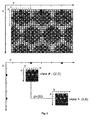
- Figure 2 illustrates a view demultiplexing and the meaning of pixel disparities.
- a view demultiplexing addresses the data conversion from the 2D raw image to the matrix of views.
- the demultiplexing process consists in reorganizing the pixels of the raw image in such a way that all pixels capturing the light rays with a certain angle of incidence are stored in the same image creating the so-called views.
- Each view is a projection of the scene under a different angle.
- the set of views create a block matrix where the central view store the pixels capturing perpendicular light rays to the sensor.
- the angular information of the light rays is given by the relative pixel positions in the micro-lens images with respect to the micro-lens-images centers.
- the view (2,3) is created by taking the pixels marked by "#" from the raw data.
- the second part of Figure 2 shows that a pixel at position (3,1) on view (5,6) has a disparity equal to 2/3, therefore it is seen at position (5,3) on the view (2,3).
- the matrix of views is only one example for calculating the level of the homogeneity. Any other suitable homogeneity detection method can be used for this purpose. For example, the calculation can be done directly on the unfocused plenoptic data, without creating the matrix of views. In addition, as described below, the embodiment of the disclosure uses only one metric (the standard deviation) for the calculation. However, any other approaches can be used, e.g., using DCT transform of the micro-lens images, or using second order statistics like co-occurrence matrices, etc.
- pixels of the micro-lens images of the unfocused plenoptic data which either have disparities equal to zero or belong to homogeneous areas as a function of the level of homogeneity of the micro-lens images of the unfocused plenoptic data are determined.
- step S102 the structure of the unfocused plenoptic data captured by the unfocused plenoptic camera will be exploited to anticipate (i) the pixels that belong to the parts of the scene that are in focus (estimated disparities of these pixels are equal to zero), or (ii) the pixels that belong to non-textured areas of the scene.
- step S103 the depth of the unfocused plenoptic data by a disparity estimation is estimated without considering the pixels determined by step S102.
- any suitable known disparity estimation methods can be used in the step S103, such as the one based on Epipolar Images of the scene disclosed in the reference 2.
- a Maximum a posteriori approach for disparity estimation was disclosed in the reference written by T.E. Bishop and P. Favaro, "Full-resolution depth map estimation from an aliased plenoptic light field", ACCV 2010 (hereinafter referred to as reference 3), which can also be used in the step S103.
- view I i,j denotes the view in the row i, and column j of the matrix of views.
- a non-zero disparity value d means that on another view of the scene I k,l (view I k,l denotes the view in the row k, and column I of the matrix of views), the pixel coordinates (x,y) have been changed to (x+d*[k-i], y+d*[j-l]). That is, the pixels are moved from one micro-lens image to another when the views are changed, as shown in Figure 2 .
- the displacement cannot be estimated using the above mentioned block-matching approaches.
- the block matching approaches try to locally estimate the displacement by comparing pixel intensities which are more or less the same in homogenous areas. In such cases, it is useless to try to estimate the pixel disparities. The disparities for such homogenous areas are initiated as 0.
- the method by pre-processing the raw data, it can prevent any disparity estimation method to spend time on estimating disparities for: (i) pixels that are in focus, (ii) pixels that belong to homogenous areas of the scene. Therefore, the method can removes the computational costs of disparity estimation on homogeneous areas, as well as in-focus areas of the captured scene. It also reduces the amount of foreground fattening introduced by disparity estimation methods that are based on block-matching solutions.
- Figure 3 is a flowchart illustrating the process.
- a level of homogeneity of micro-lens images is determined according to the standard deviations of images on three color channels.
- the method of the process of Figure 3 preferably works when the vignetting of the camera is approximately circumvented by any valid approach.
- the correction of vignetting can be done using different methods and the detail of vignetting correction is out of the focus of this disclosure.
- the raw data is divided by the white image corresponding to the same focus and zoom of the camera to correct vignetting.
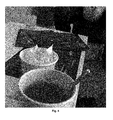
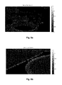
- Figure 4 illustrates an image obtained by a known Lytro camera.
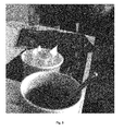
- Figure 5 illustrates the raw data after correction of vignetting by division by white image.
- the main drawback of having vignetting is the difference of the illumination in the matrix of views, i.e., the peripheral sub-aperture views are low illuminated.
- this illumination difference is reduced by dividing the raw data by a corresponding white image.
- the reason for using a corresponding white image is that the position of the microlens images on the sensor depends on the camera parameters, e.g., zoom and focus of the camera, and therefore an image of a flat white scene gives the maximum achievable capture for each pixel for each camera parameter set.
- the values on the white image therefore provide the weigthing coefficients that are due to vignetting.
- Figure 6 illustrates a zoom-in at the area shown by the rectangle in Figure 5 .
- Figure 6 the inhomogeneity of the micro-lens images on high frequencies and out of focus parts of the scene are shown.
- the 3 color channels will be treated separately in this embodiment.
- the micro-lens centers can be estimated, for example, using the method described in the reference 1. Then, with the micro-lens centers, every micro-lens image is considered, and 3 color channels of that image are independently normalized in terms of energy. On every channel, the standard deviation (Std) of the normalized data is calculated and stored in the corresponding color channel of the output matrix (hereinafter referred to as Std matrix).
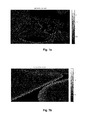
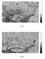
- Figures 7a and 7b illustrate the standard deviation matrix for the Red channel and a zoom in. As shown in Figures7a and 7b , only the pixels in red channel are considered. The standard deviation of these values is calculated per micro-lens. So there is one standard deviation per pixel in each view since one micro-lens contributes or provides one pixel to each view. As described below, with the demultiplexing in this embodiment, empty pixels will be inserted to address sampling, and therefore we have pixels with no standard deviations.
- Figures 8a and 8b illustrate the standard deviation matrix for the Green channel and a zoom in. Similar to the red channel, only the pixels in green channel are considered. The standard deviation of these values is calculated per micro-lens.
- Figures 9a and 9b illustrate the standard deviation matrix for the Blue channel and a zoom in. Only the pixels in blue channel are considered. The standard deviation of these values is calculated per micro-lens.
- step S302 the results of step S301 is subject to a thresholding to obtain a binary mask, showing which pixels are estimated to either have disparities equal to zero or belong to homogeneous areas.
- This binary mask is of the size of one view and has the same demuliplexing pattern as an extracted view to properly address sampling of the light field.
- a threshold on the standard deviation is set.
- the output binary mask at that position is set to 0. Otherwise, the binary mask is set to 1.
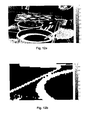
- Figures 10a and 10b illustrate the thresholded binary mask and a zoom in.
- the effect of noise is removed by considering all three channel Std maps. It can be appreciated that in natural images, the chromatic channels correlate in patterns, which means that similar high frequency contents can be seen in the three channels. That is why the three channels are thresholded simultaneously.
- the empty pixels of demultiplexing are filled with morphological filters.
- step S303 it applies morphological filtering to fill the empty pixels that are inserted to address the sampling, regarding their neighboring pixels.
- the result of this step can be used to decide whether the disparities should be estimated or not.
- Both of the Std matrix obtained by the step S301 and the binary mask obtained by the step S302 follow the demultiplexing pattern of the light field, i.e., empty pixels are inserted in positions of non-existing micro-lenses to follow the sampling of the light field.
- this embodiment with the additional steps S302 and S303 can reduce the computational costs of disparity estimation.
- a morphological filtering is applied on the results of the step S302 to fill in the empty pixels according to their neighboring pixels. This is needed when a demultiplexing (such as what is discussed in the reference 1) is used. Next, a more detailed description will be given in this step.
- the structure element (SE) as a 2 by 2 matrix of ones are defined, and (1 st) the binary mask is dilated our by such structure element SE; and (2nd) the results of the 1 st step are eroded by the same structure element SE.
- Figures 11 a and 11 b illustrate the results of dilation (1 st step) and a zoom in.
- Figures 12a and 12b illustrate the results of erosion (2nd step) and a zoom in.
- the result image contains only 0s and 1 s, where 0s addresses the pixels which were already known that disparity estimation is not necessary and 1 s refers to pixels for which the disparity estimation is needed.
- step S303 can be used in any disparity estimation method to estimate the depth of the unfocused plenoptic data.
- the depth will be estimated by the disparity estimation without considering the determined pixels which either have disparities equal to zero or belong to homogeneous areas.
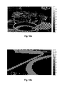
- Figure 13 illustrates an image showing the estimated disparities using the block matching method described in the reference 1 without using the method of the embodiment of the disclosure.
- Figure 14 illustrates an image showing the estimated disparities with the method of the embodiment of the disclosure. As shown in Figure 14 , less number of pixels requires disparity estimation compared with the case in Figure 13 . These pixels are well-detected to contain high frequencies on out of focus parts of the scene. Besides, the foreground fattening of the block matching method is removed, which can be observed by looking at the thin edges on this disparity map, compared to the ones in Figure 13 .
- the accuracy of the results is increased, thanks to the proposed pre-processing module of disparity anticipation.
- the block matching methods suffer from foreground fattening effect, meaning that the estimated disparities on the scene edges are accurate, but moving away from the edges in a close neighborhood, the disparities are mistakenly estimated as equal to the disparity of edges, i.e., the edges on the disparity maps are fattened. This results in having wrong disparity values of the background around the edges of foreground.
- the embodiments of the disclosure can prevent the disparity map from such inaccuracies by accurately detecting the edges and blurred high frequencies, and discarding the disparity estimation elsewhere.
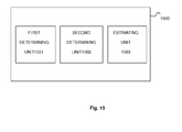
- Figure 15 is a block diagram of an apparatus for estimating a depth of unfocused plenoptic data according to an embodiment of the present disclosure.
- the apparatus 1500 for estimating the depth of unfocused plenoptic data comprises a first determining unit 1501 for determining a level of the homogeneity of micro-lens images of unfocused plenoptic data.
- the apparatus 1500 further comprises a second determining unit 1502 for determining pixels of the micro-lens images of the unfocused plenoptic data which either have disparities equal to zero or belong to homogeneous areas as a function of the calculated level of homogeneity of the micro-lens images of the unfocused plenoptic data.
- the apparatus 1500 further comprises an estimating unit 1503 for estimating the depth of the unfocused plenoptic data by the disparity estimation without considering the determined pixels.
- the apparatus 1500 can be used for the post processing of unfocused plenoptic data captured by a plenoptic camera.
- the apparatus 1500 can be embedded in the plenoptic camera or provided as a separate device.
- the present disclosure may be implemented in various forms of hardware, software, firmware, special purpose processors, or a combination thereof.
- the software is preferably implemented as an application program tangibly embodied on a program storage device.
- the application program may be uploaded to, and executed by, a machine comprising any suitable architecture.
- the machine is implemented on a computer platform having hardware such as one or more central processing units (CPU), a random access memory (RAM), and input/output (I/O) interface(s).
- CPU central processing units
- RAM random access memory
- I/O input/output
- the computer platform also includes an operating system and microinstruction code.
- the various processes and functions described herein may either be part of the microinstruction code or part of the application program (or a combination thereof), which is executed via the operating system.
- various other peripheral devices may be connected to the computer platform such as an additional data storage device and a printing device.
Landscapes
- Engineering & Computer Science (AREA)
- Physics & Mathematics (AREA)
- General Physics & Mathematics (AREA)
- Computer Vision & Pattern Recognition (AREA)
- Theoretical Computer Science (AREA)
- Optics & Photonics (AREA)
- Studio Devices (AREA)
- Image Processing (AREA)
- Image Analysis (AREA)
- Length Measuring Devices By Optical Means (AREA)
Priority Applications (7)
| Application Number | Priority Date | Filing Date | Title |
|---|---|---|---|
| EP14306887.2A EP3026628A1 (de) | 2014-11-26 | 2014-11-26 | Verfahren und Vorrichtung zur Bestimmung der Tiefe von nichtfokussierten plenoptischen Daten |
| EP15800802.9A EP3224805B1 (de) | 2014-11-26 | 2015-11-24 | Verfahren und vorrichtung zur bestimmung der tiefe von nichtfokussierten plenoptischen daten |
| CN201580063843.9A CN107004274B (zh) | 2014-11-26 | 2015-11-24 | 估计未聚焦全光数据的深度的方法和装置 |
| US15/531,408 US10510156B2 (en) | 2014-11-26 | 2015-11-24 | Method and apparatus for estimating depth of unfocused plenoptic data |
| JP2017527895A JP2017537396A (ja) | 2014-11-26 | 2015-11-24 | 非集束型プレノプティックデータの深度を推定する方法および装置 |
| PCT/EP2015/077531 WO2016083393A1 (en) | 2014-11-26 | 2015-11-24 | Method and apparatus for estimating depth of unfocused plenoptic data |
| KR1020177014285A KR102541363B1 (ko) | 2014-11-26 | 2015-11-24 | 비집속 플렌옵틱 데이터의 깊이를 추정하는 방법 및 장치 |
Applications Claiming Priority (1)
| Application Number | Priority Date | Filing Date | Title |
|---|---|---|---|
| EP14306887.2A EP3026628A1 (de) | 2014-11-26 | 2014-11-26 | Verfahren und Vorrichtung zur Bestimmung der Tiefe von nichtfokussierten plenoptischen Daten |
Publications (1)
| Publication Number | Publication Date |
|---|---|
| EP3026628A1 true EP3026628A1 (de) | 2016-06-01 |
Family
ID=52023419
Family Applications (2)
| Application Number | Title | Priority Date | Filing Date |
|---|---|---|---|
| EP14306887.2A Withdrawn EP3026628A1 (de) | 2014-11-26 | 2014-11-26 | Verfahren und Vorrichtung zur Bestimmung der Tiefe von nichtfokussierten plenoptischen Daten |
| EP15800802.9A Active EP3224805B1 (de) | 2014-11-26 | 2015-11-24 | Verfahren und vorrichtung zur bestimmung der tiefe von nichtfokussierten plenoptischen daten |
Family Applications After (1)
| Application Number | Title | Priority Date | Filing Date |
|---|---|---|---|
| EP15800802.9A Active EP3224805B1 (de) | 2014-11-26 | 2015-11-24 | Verfahren und vorrichtung zur bestimmung der tiefe von nichtfokussierten plenoptischen daten |
Country Status (6)
| Country | Link |
|---|---|
| US (1) | US10510156B2 (de) |
| EP (2) | EP3026628A1 (de) |
| JP (1) | JP2017537396A (de) |
| KR (1) | KR102541363B1 (de) |
| CN (1) | CN107004274B (de) |
| WO (1) | WO2016083393A1 (de) |
Cited By (1)
| Publication number | Priority date | Publication date | Assignee | Title |
|---|---|---|---|---|
| US20220120562A1 (en) * | 2019-02-06 | 2022-04-21 | Mitsumi Electric Co., Ltd. | Distance measuring camera |
Families Citing this family (3)
| Publication number | Priority date | Publication date | Assignee | Title |
|---|---|---|---|---|
| WO2018024490A1 (en) * | 2016-08-05 | 2018-02-08 | Thomson Licensing | A method for obtaining at least one sub-aperture image being associated with one view |
| KR102052564B1 (ko) * | 2018-03-09 | 2019-12-05 | 한국과학기술원 | 라이트 필드 이미지의 깊이 추정 방법 및 장치 |
| CN114638875A (zh) * | 2022-05-23 | 2022-06-17 | 武汉依迅北斗时空技术股份有限公司 | 基于区域均匀度的立体匹配优化方法、装置、设备及介质 |
Family Cites Families (12)
| Publication number | Priority date | Publication date | Assignee | Title |
|---|---|---|---|---|
| CN100423021C (zh) * | 2002-10-17 | 2008-10-01 | 精工爱普生株式会社 | 用于低景深图像分割的方法和装置 |
| US8559705B2 (en) * | 2006-12-01 | 2013-10-15 | Lytro, Inc. | Interactive refocusing of electronic images |
| US7792423B2 (en) * | 2007-02-06 | 2010-09-07 | Mitsubishi Electric Research Laboratories, Inc. | 4D light field cameras |
| US7962033B2 (en) * | 2008-01-23 | 2011-06-14 | Adobe Systems Incorporated | Methods and apparatus for full-resolution light-field capture and rendering |
| US8817015B2 (en) * | 2010-03-03 | 2014-08-26 | Adobe Systems Incorporated | Methods, apparatus, and computer-readable storage media for depth-based rendering of focused plenoptic camera data |
| KR101756910B1 (ko) * | 2010-05-11 | 2017-07-26 | 삼성전자주식회사 | 감쇠 패턴을 포함하는 마스크를 이용한 광 필드 영상 처리 장치 및 방법 |
| CN101883291B (zh) * | 2010-06-29 | 2012-12-19 | 上海大学 | 感兴趣区域增强的视点绘制方法 |
| JP5900017B2 (ja) | 2012-02-28 | 2016-04-06 | カシオ計算機株式会社 | 奥行き推定装置、再構成画像生成装置、奥行き推定方法、再構成画像生成方法及びプログラム |
| JP6320075B2 (ja) * | 2014-02-19 | 2018-05-09 | キヤノン株式会社 | 画像処理装置およびその制御方法 |
| US9478036B2 (en) * | 2014-04-14 | 2016-10-25 | Nokia Technologies Oy | Method, apparatus and computer program product for disparity estimation of plenoptic images |
| GB2525851B (en) * | 2014-04-30 | 2017-03-29 | Canon Kk | Method and device for encoding a sub-aperture image of a set of sub-aperture images obtained from a plenoptic image |
| CN104101331B (zh) * | 2014-07-24 | 2016-03-09 | 合肥工业大学 | 基于全光场相机的非合作目标位姿测量 |
-
2014
- 2014-11-26 EP EP14306887.2A patent/EP3026628A1/de not_active Withdrawn
-
2015
- 2015-11-24 CN CN201580063843.9A patent/CN107004274B/zh active Active
- 2015-11-24 KR KR1020177014285A patent/KR102541363B1/ko not_active Application Discontinuation
- 2015-11-24 WO PCT/EP2015/077531 patent/WO2016083393A1/en active Application Filing
- 2015-11-24 JP JP2017527895A patent/JP2017537396A/ja not_active Ceased
- 2015-11-24 EP EP15800802.9A patent/EP3224805B1/de active Active
- 2015-11-24 US US15/531,408 patent/US10510156B2/en active Active
Non-Patent Citations (4)
| Title |
|---|
| MARKUS STEFFENS ET AL: "Probabilistic Scene Analysis for Robust Stereo Correspondence", 6 July 2009, IMAGE ANALYSIS AND RECOGNITION, SPRINGER BERLIN HEIDELBERG, BERLIN, HEIDELBERG, PAGE(S) 697 - 706, ISBN: 978-3-642-02610-2, XP019122433 * |
| N. SABATER; V. DRAZIC; M. SEIFI; G. SANDRI; P. PEREZ: "Light field demultiplexing and disparity estimation", HAL, 2014 |
| NEUS SABATER ET AL: "Light-Field Demultiplexing and Disparity Estimation", 8 January 2014 (2014-01-08), XP055099221, Retrieved from the Internet <URL:http://hal.archives-ouvertes.fr/docs/00/92/56/52/PDF/iccp2014_hal.pdf> [retrieved on 20140129] * |
| S. WANNER; B. GOLDLEUKE: "Variational light field analysis for disparity estimation and super-resolution", IEEE TRANSACTION OF PATTERN ANALYSIS AND MACHINE INTELLIGENCE, 2013 |
Cited By (2)
| Publication number | Priority date | Publication date | Assignee | Title |
|---|---|---|---|---|
| US20220120562A1 (en) * | 2019-02-06 | 2022-04-21 | Mitsumi Electric Co., Ltd. | Distance measuring camera |
| US11842507B2 (en) * | 2019-02-06 | 2023-12-12 | Mitsumi Electric Co., Ltd. | Distance measuring camera |
Also Published As
| Publication number | Publication date |
|---|---|
| US10510156B2 (en) | 2019-12-17 |
| KR20170088859A (ko) | 2017-08-02 |
| US20170330339A1 (en) | 2017-11-16 |
| WO2016083393A1 (en) | 2016-06-02 |
| CN107004274A (zh) | 2017-08-01 |
| EP3224805B1 (de) | 2020-04-01 |
| JP2017537396A (ja) | 2017-12-14 |
| EP3224805A1 (de) | 2017-10-04 |
| CN107004274B (zh) | 2021-08-10 |
| KR102541363B1 (ko) | 2023-06-09 |
Similar Documents
| Publication | Publication Date | Title |
|---|---|---|
| JP7043085B2 (ja) | 視点から距離情報を取得するための装置及び方法 | |
| US10699476B2 (en) | Generating a merged, fused three-dimensional point cloud based on captured images of a scene | |
| US9818199B2 (en) | Method and apparatus for estimating depth of focused plenoptic data | |
| JP6347675B2 (ja) | 画像処理装置、撮像装置、画像処理方法、撮像方法及びプログラム | |
| TWI441095B (zh) | 距離估算方法及其距離估算裝置,及其機器可讀取媒體 | |
| EP3224805B1 (de) | Verfahren und vorrichtung zur bestimmung der tiefe von nichtfokussierten plenoptischen daten | |
| CN111107337B (zh) | 深度信息补全方法及其装置、监控系统和存储介质 | |
| KR102187211B1 (ko) | 스테레오-시간적 이미지 시퀀스들로부터 향상된 3-d 데이터 재구성을 위한 방법들 및 장치 | |
| CN108805921B (zh) | 图像获取系统及方法 | |
| JP5900017B2 (ja) | 奥行き推定装置、再構成画像生成装置、奥行き推定方法、再構成画像生成方法及びプログラム | |
| KR100764414B1 (ko) | Psf 선택 모듈, 디지털 자동 초점 조절 장치 및 psf선택 방법 | |
| CN115034988A (zh) | 一种基于rgbd相机的两阶段主体点云滤波方法 | |
| EP3099054A1 (de) | Verfahren und vorrichtung zur bestimmung eines fokalen stapels von bildern aus mit einer szene assoziierter lichtfelddaten und zugehöriges computerprogrammprodukt | |
| CN115514877B (zh) | 图像处理装置和降低噪声的方法 | |
| US20240127407A1 (en) | Image sensor apparatus for capturing depth information | |
| JP6066765B2 (ja) | 撮像装置、その制御方法、および制御プログラム | |
| Andorko et al. | A dual image processing pipeline camera with CE applications | |
| CN115619841A (zh) | 图像处理方法、装置、计算机可读存储介质及电子设备 |
Legal Events
| Date | Code | Title | Description |
|---|---|---|---|
| PUAI | Public reference made under article 153(3) epc to a published international application that has entered the european phase |
Free format text: ORIGINAL CODE: 0009012 |
|
| AK | Designated contracting states |
Kind code of ref document: A1 Designated state(s): AL AT BE BG CH CY CZ DE DK EE ES FI FR GB GR HR HU IE IS IT LI LT LU LV MC MK MT NL NO PL PT RO RS SE SI SK SM TR |
|
| AX | Request for extension of the european patent |
Extension state: BA ME |
|
| STAA | Information on the status of an ep patent application or granted ep patent |
Free format text: STATUS: THE APPLICATION IS DEEMED TO BE WITHDRAWN |
|
| 18D | Application deemed to be withdrawn |
Effective date: 20161202 |