EP3026338A1 - A combustion system for a boiler - Google Patents
A combustion system for a boiler Download PDFInfo
- Publication number
- EP3026338A1 EP3026338A1 EP14195352.1A EP14195352A EP3026338A1 EP 3026338 A1 EP3026338 A1 EP 3026338A1 EP 14195352 A EP14195352 A EP 14195352A EP 3026338 A1 EP3026338 A1 EP 3026338A1
- Authority
- EP
- European Patent Office
- Prior art keywords
- fuel
- combustion
- duct
- mixed flow
- fuel nozzle
- Prior art date
- Legal status (The legal status is an assumption and is not a legal conclusion. Google has not performed a legal analysis and makes no representation as to the accuracy of the status listed.)
- Granted
Links
Images


Classifications
-
- F—MECHANICAL ENGINEERING; LIGHTING; HEATING; WEAPONS; BLASTING
- F23—COMBUSTION APPARATUS; COMBUSTION PROCESSES
- F23D—BURNERS
- F23D99/00—Subject matter not provided for in other groups of this subclass
- F23D99/002—Burners specially adapted for specific applications
- F23D99/004—Burners specially adapted for specific applications for use in particular heating operations
- F23D99/005—Burners specially adapted for specific applications for use in particular heating operations for heating liquids, e.g. for vaporising or concentrating
-
- F—MECHANICAL ENGINEERING; LIGHTING; HEATING; WEAPONS; BLASTING
- F23—COMBUSTION APPARATUS; COMBUSTION PROCESSES
- F23C—METHODS OR APPARATUS FOR COMBUSTION USING FLUID FUEL OR SOLID FUEL SUSPENDED IN A CARRIER GAS OR AIR
- F23C7/00—Combustion apparatus characterised by arrangements for air supply
- F23C7/02—Disposition of air supply not passing through burner
-
- F—MECHANICAL ENGINEERING; LIGHTING; HEATING; WEAPONS; BLASTING
- F23—COMBUSTION APPARATUS; COMBUSTION PROCESSES
- F23C—METHODS OR APPARATUS FOR COMBUSTION USING FLUID FUEL OR SOLID FUEL SUSPENDED IN A CARRIER GAS OR AIR
- F23C5/00—Disposition of burners with respect to the combustion chamber or to one another; Mounting of burners in combustion apparatus
- F23C5/08—Disposition of burners
-
- F—MECHANICAL ENGINEERING; LIGHTING; HEATING; WEAPONS; BLASTING
- F23—COMBUSTION APPARATUS; COMBUSTION PROCESSES
- F23C—METHODS OR APPARATUS FOR COMBUSTION USING FLUID FUEL OR SOLID FUEL SUSPENDED IN A CARRIER GAS OR AIR
- F23C7/00—Combustion apparatus characterised by arrangements for air supply
-
- F—MECHANICAL ENGINEERING; LIGHTING; HEATING; WEAPONS; BLASTING
- F23—COMBUSTION APPARATUS; COMBUSTION PROCESSES
- F23D—BURNERS
- F23D1/00—Burners for combustion of pulverulent fuel
-
- F—MECHANICAL ENGINEERING; LIGHTING; HEATING; WEAPONS; BLASTING
- F23—COMBUSTION APPARATUS; COMBUSTION PROCESSES
- F23D—BURNERS
- F23D14/00—Burners for combustion of a gas, e.g. of a gas stored under pressure as a liquid
- F23D14/02—Premix gas burners, i.e. in which gaseous fuel is mixed with combustion air upstream of the combustion zone
- F23D14/04—Premix gas burners, i.e. in which gaseous fuel is mixed with combustion air upstream of the combustion zone induction type, e.g. Bunsen burner
-
- F—MECHANICAL ENGINEERING; LIGHTING; HEATING; WEAPONS; BLASTING
- F23—COMBUSTION APPARATUS; COMBUSTION PROCESSES
- F23D—BURNERS
- F23D23/00—Assemblies of two or more burners
-
- F—MECHANICAL ENGINEERING; LIGHTING; HEATING; WEAPONS; BLASTING
- F23—COMBUSTION APPARATUS; COMBUSTION PROCESSES
- F23K—FEEDING FUEL TO COMBUSTION APPARATUS
- F23K3/00—Feeding or distributing of lump or pulverulent fuel to combustion apparatus
- F23K3/02—Pneumatic feeding arrangements, i.e. by air blast
-
- F—MECHANICAL ENGINEERING; LIGHTING; HEATING; WEAPONS; BLASTING
- F23—COMBUSTION APPARATUS; COMBUSTION PROCESSES
- F23C—METHODS OR APPARATUS FOR COMBUSTION USING FLUID FUEL OR SOLID FUEL SUSPENDED IN A CARRIER GAS OR AIR
- F23C2201/00—Staged combustion
- F23C2201/10—Furnace staging
- F23C2201/101—Furnace staging in vertical direction, e.g. alternating lean and rich zones
-
- F—MECHANICAL ENGINEERING; LIGHTING; HEATING; WEAPONS; BLASTING
- F23—COMBUSTION APPARATUS; COMBUSTION PROCESSES
- F23C—METHODS OR APPARATUS FOR COMBUSTION USING FLUID FUEL OR SOLID FUEL SUSPENDED IN A CARRIER GAS OR AIR
- F23C2900/00—Special features of, or arrangements for combustion apparatus using fluid fuels or solid fuels suspended in air; Combustion processes therefor
- F23C2900/06041—Staged supply of oxidant
-
- F—MECHANICAL ENGINEERING; LIGHTING; HEATING; WEAPONS; BLASTING
- F23—COMBUSTION APPARATUS; COMBUSTION PROCESSES
- F23D—BURNERS
- F23D2201/00—Burners adapted for particulate solid or pulverulent fuels
- F23D2201/20—Fuel flow guiding devices
-
- F—MECHANICAL ENGINEERING; LIGHTING; HEATING; WEAPONS; BLASTING
- F23—COMBUSTION APPARATUS; COMBUSTION PROCESSES
- F23D—BURNERS
- F23D2900/00—Special features of, or arrangements for burners using fluid fuels or solid fuels suspended in a carrier gas
- F23D2900/00003—Fuel or fuel-air mixtures flow distribution devices upstream of the outlet
-
- F—MECHANICAL ENGINEERING; LIGHTING; HEATING; WEAPONS; BLASTING
- F23—COMBUSTION APPARATUS; COMBUSTION PROCESSES
- F23K—FEEDING FUEL TO COMBUSTION APPARATUS
- F23K2203/00—Feeding arrangements
- F23K2203/006—Fuel distribution and transport systems for pulverulent fuel
-
- F—MECHANICAL ENGINEERING; LIGHTING; HEATING; WEAPONS; BLASTING
- F23—COMBUSTION APPARATUS; COMBUSTION PROCESSES
- F23K—FEEDING FUEL TO COMBUSTION APPARATUS
- F23K2203/00—Feeding arrangements
- F23K2203/008—Feeding devices for pulverulent fuel
Definitions
- the present disclosure relates to a combustion system and more particularly a combustion system that is part of a boiler for electric power generation.
- Boilers for electric power generation often have combustion systems with furnaces that are fired with solid fuel, such as bituminous coal, lignite, biomass, etc.; these combustion systems are usually provided with mills and ducting for supplying the pulverized fuel to one or more burners.
- Combustion system for lignite coals commonly operate in such way that the nitrogen oxide emissions (NOx) are achieved without application of secondary measures such as selective catalytic reduction (SCR) or selective non-catalytic reduction (SNCR) technology.
- SCR selective catalytic reduction
- SNCR selective non-catalytic reduction
- the current limits in Europe referred to NOx emission are less than 200 mg/m 3 (dry flue gas, reference 6% Oxygen (O 2 ), measured as Nitrogen dioxide (NO 2 )).
- a pulverized a fuel firing apparatus comprising a pulverized fuel injection compartment so constructed that the combined amount of primary air and secondary air to be consumed is less than the theoretical amount of air required for the combustion of the pulverized fuel, a second pulverized fuel injection compartment so constructed that the combined primary and secondary air amount is substantially equal to the theoretical air for the pulverized fuel, and a supplementary air compartment for injecting supplementary air into the furnace.
- the three compartments are arranged close to one another and control the NOx production upon combustion of the pulverized fuel.
- the present disclosure describes a system and a method for combustion of solid fuels that will be presented in the following simplified summary to provide a basic understanding of one or more aspects of the disclosure that are intended to overcome the discussed drawbacks, but to include all advantages thereof, along with providing some additional advantages.
- This summary is not an extensive overview of the disclosure. It is intended to neither identify key or critical elements of the disclosure, nor to delineate the scope of the present disclosure. Rather, the sole purpose of this summary is to present some concepts of the disclosure, its aspects and advantages in a simplified form as a prelude to the more detailed description that is presented hereinafter
- An object of the present disclosure is to propose a system and a method for combustion of solid fuels which can be used in existing and in new installations, in particular in coal or biomass fired boilers, and which significantly reduce the emission of pollutants, primarily Nitrogen oxides (NOx) and to improve part-load operability of burners of the combustion system.
- pollutants primarily Nitrogen oxides (NOx) and to improve part-load operability of burners of the combustion system.
- the present invention offers a technical solution for both improved (NOx) emission and improved part-load operability of the burner .
- the combustion system is able to create a fuel-rich phase in the center of a fuel nozzle.
- the concentration of the solid fuel in the center allows operation of the burners with minimum NOx emissions. By adopting this means the burners operate as a Low NOx burners.
- a further aspect of the present disclosure includes tilted secondary air nozzles.
- the tilted secondary air nozzles allow influencing the combustion process. By adopting this means it is possible to further reduce NOx emissions and improve flame stability during start-up or part load operation of the burners.
- a system for combustion having at least one burner to supply a mixed flow of fuel and primary air through at least one fuel nozzle to a combustion chamber. Further a fuel concentrator concentrates the mixed flow of fuel and primary air in centre of the at least one fuel nozzle. Secondary air nozzles arranged above and below the at least one fuel nozzle to inject secondary air in order to maintain a stable in the combustion chamber.
- the present disclosure also refers to a method for combustion:
- Fig 1a shows side view and Fig 1b shows top view of a combustion system 10 having burners 180 which supply a mixed flow of fuel and primary air through at least one fuel nozzle 40 to the combustion chamber 30 for example of a boiler 1.
- the duct 150 is further bends in such a way that one portion is vertical with respect parallel to axis of the boiler 1 A-A is vertical duct 75 and other portion is horizontal duct 80 which is parallel to axis B-B of the fuel nozzle 40.
- the duct 150 is equipped with a fuel concentrator 5.
- the fuel concentrator 5 concentrates the mixed flow of fuel and primary air in center 60 of the fuel nozzle 40.
- Secondary air nozzles 50 are arranged above and below the fuel nozzle 40 to inject an secondary air in order to provide stable combustion of the mixed flow of fuel and primary air in the combustion chamber 30 for example of the boiler 1.
- An axis C-C' of secondary nozzles 50 is parallel to the axis B-B of the fuel nozzle 40.
- the fuel nozzle 40 is having a fuel nozzle 190 and core air tubes 290.
- the fuel concentrator 5 is having at least one deflector 120 and at least one diverger 130.
- the deflector 120 has an angle with a wall 200 of duct 150 such that the mixed flow of fuel and air along the wall 200 of the duct 150 is directed towards a center 140 of the duct 150.
- a sudden change in terms of volume of the duct 150 is provided such that the diameter of the duct 150 has been reduced within range of 50% to 80% of the original diameter and more specifically 65% of the original diameter by angling both sides 210,220 of one wall 200 in a slope converging towards the center of the duct 15 to point P and P'.
- the other wall 230 of the duct 150 can also be angled from both sides in a slope converging towards the center of the duct 15.
- Both the walls 200, 230 can also be angled simultaneously in the slope converging towards the center 140 of the duct 150.
- This sudden change in terms of volume not only change the momentum of fuel particles but also change the direction of the whole mixed flow of fuel and primary air towards the center 140 of the duct 150 and thereafter the mixed flow of fuel and primary air moves in the center 140 of the duct 150.
- particles having large mass for example coal particles having size more than approximately 200 microns of the concentrated mixed flow of fuel and primary air move in the center 140 of the duct 150 to form a fuel-rich concentrated jet 70 in the center 60 of the fuel nozzle 40 as the change in the velocity does not change the momentum due to the large mass of the particles as shown in Fig 3a and 3b .
- the diverger 130 expands the duct 150 backs to original volume of the duct 150 by angling both sides 240, 250 of the one wall 200 in a slope diverge towards the original diameter of the duct 150 from the point P and P'.
- the other wall 230 of the duct 150 can be angled from both sides in a slope diverging towards the original diameter of the duct 150. Both the walls 200, 230 can also be angled simultaneously in a slope diverging towards the original diameter of the duct 150.
- particles having small mass for example coal particles having size less than approximately 200 microns of the concentrated mixed flow of fuel and air again moves along the at least one diverger 130 towards the wall 200 of the duct 150 to form a lean fuel concentrated jet 160 in other sections 170 of the fuel nozzle 40 as shown in Fig 3a and 3b .
- This change in terms of achieving the original volume provides space for the light particles which due to high momentum start moving along the sides 240, 250, leads to change in the direction of the lean fuel concentrated jet 160 in area near the walls 200, 230 of the duct 150 and further in other sections 170 of the fuel nozzle 40.
- the duct 150 can be a straight duct with the fuel concentrator 5 equipped anywhere on the duct 150 depending upon the type of fuel and combustion requirements.
- the fuel-rich concentrated jet 70 and the lean fuel concentrated jet 160 is generated in the horizontal duct 80 upstream of the fuel nozzle 40 as the changes in velocity and direction leads to the creation and separation of concentrated jet.
- This position provides an advantage in terms that the fuel-rich concentrated jet 70 is not able to change its direction due to a very short distance which is to traveled before reaching outlet 260 of the fuel nozzle 40 and due to space the lean fuel concentrated jet 160 quickly moves towards the walls 200, 230 of the duct 150 as there is high momentum of the light particles and travel in other sections 170 of the fuel nozzle 40 before reaching the outlet 260 of the fuel nozzle 40.
- the fuel concentrator 5 can be equipped on any of the walls 200, 230 or on both the walls 200, 230.
- the fuel concentrator 5 is armored to withstand unavoidable wear. The pressure loss of the fuel concentrator 5 is limited. To enhance the positive effects the burner 180 needs to be combined with tilted secondary air nozzles 50.
- Fig 1c illustrates the front view of the outlet 260 of the fuel nozzle 40.
- the fuel-rich concentrated jet 70 increase the concentration of the mixed flow of fuel and primary air in the center 60 of the fuel nozzle 40 and the lean fuel concentrated jet 160 decrease the concentration of the mixed flow of fuel and primary air in the other section 170 of the fuel nozzle 40.
- central part 90 of the fuel-rich concentrated jet 70 is ignited in the combustion chamber 30 after it is supplied through outlet 260 of the fuel nozzle 40.
- the fuel-rich concentrated jet 70 is rich in coal leads to improved gasification of the mixed flow of fuel and primary air and is a key factor in improved NOx emission performance of the burner 180.
- the combustion system 10 is combined with means to improve mixing of the mixed flow of fuel and primary air with secondary air improves ignition and flame stability.
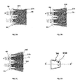
- Fig.2a, 2b 2c and 2d illustrate the secondary air tilting.
- flame 100 can either be prolonged or shortened.
- Fig.2a where in another embodiment the secondary air nozzles 50 are tilted relative to axis B-B of the fuel nozzle 40 to adjust angle of injected secondary air in the combustion of the fuel-rich concentrated jet 70. Secondary air tilting allows further control of the flame 100 and combustion.
- the secondary air nozzles 50 is tilted in a converging angle towards the axis B-B of the fuel nozzle 40 to combust the mixed flow of fuel and air 20 to obtain a shortened flame 270. Shortening of the flame 100 will enhance ignition and flame stability. This setting will be used either during ignition of the burner 180 or in part-load operation of the burner 180.
- Fig 2b depicts the normal secondary air setting with no deflections at medium burner loads having flame 100.
- the secondary air nozzles 50 is tilted in a diverging angle away from the axis B-B of the fuel nozzle 40 to combust the mixed flow of fuel and primary air to obtain a prolonged flame 280. Prolonging of the flame 100 leads will further decrease NOx emissions.
- the operational mode will be used when the burner 180 is in full load and operation.
- Guiding vanes 110 are provided with the secondary air nozzles 50 as an alternative means to deflect the injected secondary air in the combustion of the mixed flow of fuel and primary air.
- Fig.3a illustrates gas velocities distribution in the burner 180 and at the fuel nozzle 40, derived from CFD analysis.
- the gas velocities have been increased in the center 140 of the duct 150 as well as in the center 60 of the fuel nozzle 40 as jet of mixed flow of fuel and primary air is created with the fuel concentrator 5 as observed in form of concentrated mark shown in figure.
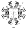
- Fig 4 shows top view of the boiler 1 having burners 180 arranged tangentially with the mixed flow of fuel and air is injected on the boiler walls, representing the arrangement in lignite-fired boilers.
- the injection of the mixed flow of fuel and air 20 creates a vertical vortex in the center of the combustion chamber.
- the mixed of fuel and primary air is supplied through the duct 150 of the burner 180 into the combustion chamber 30 via the fuel nozzle 40. Concentration of the mixed of fuel and air is done by the fuel concentrator 5 in the center 60 of the fuel nozzle 40. Injection of the secondary air controls the combustion of the mixed flow of fuel and air in the combustion chamber 30 through secondary air nozzles which are arranged above and below the fuel nozzle 40.
- the burner may consist of one or more fuel nozzles 40.
- Fuel concentrator 5 is having at least one deflector 120 and at least one diverger 130.
- the angling of a wall 200 of the at least one deflector 120 directs the mixed flow of fuel and primary air along the wall 200 of the duct 150 towards the center 140 of the duct 150 to the point P and P'. Particles of the mixed flow of fuel and primary air having large mass moves in the center 140 of the duct 150 to form the fuel rich concentrated jet 70 in the center 60 of the fuel nozzle 40.
- the diverger 130 expand the duct 150 back to the original volume of the duct 150 allowing the movement of particles having small mass of the concentrated mixed flow of fuel and primary air along the at least one diverger 130 towards the wall 200 of the duct 150 to form a lean fuel concentrated jet 160 in other sections 170 of the fuel nozzle 40.
- Further tilting of the secondary air nozzles 50 relative to the axis B-B' of the fuel nozzle 40 is done to adjust the angle of the injected secondary air in the combustion of the fuel-rich concentrated jet 70 to make the flame 100 either prolonged or shortened .
- By tilting the secondary air nozzles in the converging angle towards the axis of the fuel nozzle 40 to combust the mixed flow of fuel and air results in the shortened flame 280.
- the burner of the present disclosure is a reliable jet burner in such way to generate a concentrated fuel jet in the center of the fuel nozzle.
- the mixed flow of fuel and air fuel concentration increases in the center area of the fuel nozzle, while the fuel concentration in the other sections of the fuel nozzle decreases. From a combustion point of view this leads to a prolonged flame with distinct sub- and over-stoichiometric conditions.
- the burner base NOx emission will be lower. In effect the burner becomes a Low NOx burner. Also the burner firing part load capability has been improved.
- the burner of the present disclosure sticks to the existing and reliable jet burner design. The burner is compatible with the available mill systems.
Landscapes
- Engineering & Computer Science (AREA)
- Chemical & Material Sciences (AREA)
- Combustion & Propulsion (AREA)
- Mechanical Engineering (AREA)
- General Engineering & Computer Science (AREA)
Abstract
Description
- The present disclosure relates to a combustion system and more particularly a combustion system that is part of a boiler for electric power generation.
- Boilers for electric power generation often have combustion systems with furnaces that are fired with solid fuel, such as bituminous coal, lignite, biomass, etc.; these combustion systems are usually provided with mills and ducting for supplying the pulverized fuel to one or more burners. Combustion system for lignite coals commonly operate in such way that the nitrogen oxide emissions (NOx) are achieved without application of secondary measures such as selective catalytic reduction (SCR) or selective non-catalytic reduction (SNCR) technology. The current limits in Europe referred to NOx emission are less than 200 mg/m3 (dry flue gas, reference 6% Oxygen (O2), measured as Nitrogen dioxide (NO2)).
- Generally, during the combustion process of fossil fuels pollutants such as Nitrogen oxides (NOx) are generated. If allowed to enter the atmosphere, these pollutants can detrimentally impact the environment and pose health hazards to humans and animals.
US4669398 discloses a pulverized a fuel firing apparatus comprising a pulverized fuel injection compartment so constructed that the combined amount of primary air and secondary air to be consumed is less than the theoretical amount of air required for the combustion of the pulverized fuel, a second pulverized fuel injection compartment so constructed that the combined primary and secondary air amount is substantially equal to the theoretical air for the pulverized fuel, and a supplementary air compartment for injecting supplementary air into the furnace. The three compartments are arranged close to one another and control the NOx production upon combustion of the pulverized fuel. - State-of-the-art combustion systems for lignite are designed to achieve the actual NOx emission limits of less than 200 mg/m3. It is likely that soon more stringent norms will be applicable. Consequently there is need to provide combustion systems which achieve actual emissions level much less than 200mg/ m3.
- The present disclosure describes a system and a method for combustion of solid fuels that will be presented in the following simplified summary to provide a basic understanding of one or more aspects of the disclosure that are intended to overcome the discussed drawbacks, but to include all advantages thereof, along with providing some additional advantages. This summary is not an extensive overview of the disclosure. It is intended to neither identify key or critical elements of the disclosure, nor to delineate the scope of the present disclosure. Rather, the sole purpose of this summary is to present some concepts of the disclosure, its aspects and advantages in a simplified form as a prelude to the more detailed description that is presented hereinafter
- An object of the present disclosure is to propose a system and a method for combustion of solid fuels which can be used in existing and in new installations, in particular in coal or biomass fired boilers, and which significantly reduce the emission of pollutants, primarily Nitrogen oxides (NOx) and to improve part-load operability of burners of the combustion system.
- The present invention offers a technical solution for both improved (NOx) emission and improved part-load operability of the burner . The combustion system is able to create a fuel-rich phase in the center of a fuel nozzle. The concentration of the solid fuel in the center allows operation of the burners with minimum NOx emissions. By adopting this means the burners operate as a Low NOx burners. A further aspect of the present disclosure includes tilted secondary air nozzles. The tilted secondary air nozzles allow influencing the combustion process. By adopting this means it is possible to further reduce NOx emissions and improve flame stability during start-up or part load operation of the burners. Various other objects and features of the present disclosure will be apparent from the following detailed description and claims.
- According to aspects disclosed herein, there is provided a system for combustion having at least one burner to supply a mixed flow of fuel and primary air through at least one fuel nozzle to a combustion chamber. Further a fuel concentrator concentrates the mixed flow of fuel and primary air in centre of the at least one fuel nozzle. Secondary air nozzles arranged above and below the at least one fuel nozzle to inject secondary air in order to maintain a stable in the combustion chamber.
- The present disclosure also refers to a method for combustion:
- supplying a mixed flow of fuel and primary air by at least one burner through at least one fuel nozzle to a combustion chamber;
- concentrating the mixed flow of fuel and primary air in centre of the at least one fuel nozzle with a fuel concentrator;
- injecting secondary air in order to control the combustion of the mixed flow of fuel and primary air in the combustion chamber through secondary air nozzles which are arranged above and below the at least one fuel nozzle.
- These together with the other aspects of the present disclosure, along with the various features of novelty that characterize the present disclosure, are pointed out with particularity in the present disclosure. For a better understanding of the present disclosure, its operating advantages, and its uses, reference should be made to the accompanying drawings and descriptive matter in which there are illustrated exemplary embodiments of the present disclosure.
- The advantages and features of the present disclosure will be better understood with reference to the following detailed description and claims taken in conjunction with the accompanying drawings, wherein like elements are identified with like symbols, and in which:
-
Fig.1a is a side view of a combustion system, in accordance with an exemplary embodiment of the present disclosure; -
Fig.1b is a top view of the combustion system, in accordance with an exemplary embodiment of the present disclosure; -
Fig.1c is a front view of outlet of a burner with two fuel nozzles and secondary air nozzles above and below the fuel nozzles in accordance with an exemplary embodiment of the present disclosure; -
Fig.2a-d illustrates secondary air tilting in accordance with an exemplary embodiment of the present disclosure; -
Fig.3a illustrates gas velocities in the burner and at the fuel nozzle in accordance with an exemplary embodiment of the present disclosure; -
Fig.3b illustrates fuel distribution in the burner and at the air/fuel nozzle in accordance with an exemplary embodiment of the present disclosure; -
Fig.4 illustrates top view of a boiler having burners arranged tangentially in accordance with an exemplary embodiment of the present disclosure; -
Fig 1a .shows side view andFig 1b shows top view of acombustion system 10 havingburners 180 which supply a mixed flow of fuel and primary air through at least onefuel nozzle 40 to thecombustion chamber 30 for example of a boiler 1. The mixed flow of fuel and primary air supplied to theburner 180 through aduct 150 from a pulverizer (not shown) where the fuel is grinded to the required finesse. Theduct 150 is further bends in such a way that one portion is vertical with respect parallel to axis of the boiler 1 A-A isvertical duct 75 and other portion ishorizontal duct 80 which is parallel to axis B-B of thefuel nozzle 40. Theduct 150 is equipped with a fuel concentrator 5. The fuel concentrator 5 concentrates the mixed flow of fuel and primary air incenter 60 of thefuel nozzle 40.Secondary air nozzles 50 are arranged above and below thefuel nozzle 40 to inject an secondary air in order to provide stable combustion of the mixed flow of fuel and primary air in thecombustion chamber 30 for example of the boiler 1. An axis C-C' ofsecondary nozzles 50 is parallel to the axis B-B of thefuel nozzle 40. Thefuel nozzle 40 is having afuel nozzle 190 andcore air tubes 290. In one embodiment of the present disclosure the fuel concentrator 5 is having at least onedeflector 120 and at least one diverger 130. In another embodiment thedeflector 120 has an angle with awall 200 ofduct 150 such that the mixed flow of fuel and air along thewall 200 of theduct 150 is directed towards acenter 140 of theduct 150. A sudden change in terms of volume of theduct 150 is provided such that the diameter of theduct 150 has been reduced within range of 50% to 80% of the original diameter and more specifically 65% of the original diameter by angling both sides 210,220 of onewall 200 in a slope converging towards the center of the duct 15 to point P and P'. Theother wall 230 of theduct 150 can also be angled from both sides in a slope converging towards the center of the duct 15. Both thewalls center 140 of theduct 150. This sudden change in terms of volume not only change the momentum of fuel particles but also change the direction of the whole mixed flow of fuel and primary air towards thecenter 140 of theduct 150 and thereafter the mixed flow of fuel and primary air moves in thecenter 140 of theduct 150. In another embodiment particles having large mass for example coal particles having size more than approximately 200 microns of the concentrated mixed flow of fuel and primary air move in thecenter 140 of theduct 150 to form a fuel-richconcentrated jet 70 in thecenter 60 of thefuel nozzle 40 as the change in the velocity does not change the momentum due to the large mass of the particles as shown inFig 3a and 3b . This leads to continuous motion of the fuel-richconcentrated jet 70 in thecenter 140 of theduct 150 and further in thecenter 60 of thefuel nozzle 40 as shown inFig 3a and 3b . In another embodiment the diverger 130 expands theduct 150 backs to original volume of theduct 150 by angling bothsides wall 200 in a slope diverge towards the original diameter of theduct 150 from the point P and P'. Theother wall 230 of theduct 150 can be angled from both sides in a slope diverging towards the original diameter of theduct 150. Both thewalls duct 150. In another embodiment particles having small mass for example coal particles having size less than approximately 200 microns of the concentrated mixed flow of fuel and air again moves along the at least one diverger 130 towards thewall 200 of theduct 150 to form a lean fuel concentratedjet 160 inother sections 170 of thefuel nozzle 40 as shown inFig 3a and 3b . This change in terms of achieving the original volume provides space for the light particles which due to high momentum start moving along thesides jet 160 in area near thewalls duct 150 and further inother sections 170 of thefuel nozzle 40. Theduct 150 can be a straight duct with the fuel concentrator 5 equipped anywhere on theduct 150 depending upon the type of fuel and combustion requirements. For better results the fuel-richconcentrated jet 70 and the lean fuel concentratedjet 160 is generated in thehorizontal duct 80 upstream of thefuel nozzle 40 as the changes in velocity and direction leads to the creation and separation of concentrated jet. This position provides an advantage in terms that the fuel-richconcentrated jet 70 is not able to change its direction due to a very short distance which is to traveled before reachingoutlet 260 of thefuel nozzle 40 and due to space the lean fuel concentratedjet 160 quickly moves towards thewalls duct 150 as there is high momentum of the light particles and travel inother sections 170 of thefuel nozzle 40 before reaching theoutlet 260 of thefuel nozzle 40. The fuel concentrator 5 can be equipped on any of thewalls walls burner 180 needs to be combined with tiltedsecondary air nozzles 50. -
Fig 1c illustrates the front view of theoutlet 260 of thefuel nozzle 40. The fuel-richconcentrated jet 70 increase the concentration of the mixed flow of fuel and primary air in thecenter 60 of thefuel nozzle 40 and the lean fuel concentratedjet 160 decrease the concentration of the mixed flow of fuel and primary air in theother section 170 of thefuel nozzle 40. In another embodimentcentral part 90 of the fuel-richconcentrated jet 70 is ignited in thecombustion chamber 30 after it is supplied throughoutlet 260 of thefuel nozzle 40. The fuel-richconcentrated jet 70 is rich in coal leads to improved gasification of the mixed flow of fuel and primary air and is a key factor in improved NOx emission performance of theburner 180. Thecombustion system 10 is combined with means to improve mixing of the mixed flow of fuel and primary air with secondary air improves ignition and flame stability. -
Fig.2a, 2b 2c and 2d illustrate the secondary air tilting. By adjusting the angle of the injected secondary air,flame 100 can either be prolonged or shortened. - In
Fig.2a where in another embodiment thesecondary air nozzles 50 are tilted relative to axis B-B of thefuel nozzle 40 to adjust angle of injected secondary air in the combustion of the fuel-richconcentrated jet 70. Secondary air tilting allows further control of theflame 100 and combustion. Thesecondary air nozzles 50 is tilted in a converging angle towards the axis B-B of thefuel nozzle 40 to combust the mixed flow of fuel and air 20 to obtain a shortenedflame 270. Shortening of theflame 100 will enhance ignition and flame stability. This setting will be used either during ignition of theburner 180 or in part-load operation of theburner 180. -
Fig 2b depicts the normal secondary air setting with no deflections at medium burnerloads having flame 100. - As illustrated in
Fig 2c . thesecondary air nozzles 50 is tilted in a diverging angle away from the axis B-B of thefuel nozzle 40 to combust the mixed flow of fuel and primary air to obtain aprolonged flame 280. Prolonging of theflame 100 leads will further decrease NOx emissions. The operational mode will be used when theburner 180 is in full load and operation. - In
Fig 2d ,Guiding vanes 110 are provided with thesecondary air nozzles 50 as an alternative means to deflect the injected secondary air in the combustion of the mixed flow of fuel and primary air. -
Fig.3a illustrates gas velocities distribution in theburner 180 and at thefuel nozzle 40, derived from CFD analysis. The gas velocities have been increased in thecenter 140 of theduct 150 as well as in thecenter 60 of thefuel nozzle 40 as jet of mixed flow of fuel and primary air is created with the fuel concentrator 5 as observed in form of concentrated mark shown in figure. - As seen in
Fig 3b fuel distribution in theburner 180 and at thefuel nozzle 40, derived from CFD analysis. The fuel distribution with fuel-richconcentrated jet 70 has been created in thecenter 140 of theduct 150 as well as in thecenter 60 of thefuel nozzle 40 as observed in form of concentrated line shown in figure. -
Fig 4 shows top view of the boiler 1 havingburners 180 arranged tangentially with the mixed flow of fuel and air is injected on the boiler walls, representing the arrangement in lignite-fired boilers. The injection of the mixed flow of fuel and air 20 creates a vertical vortex in the center of the combustion chamber. - In a method for combustion according to the present disclosure the mixed of fuel and primary air is supplied through the
duct 150 of theburner 180 into thecombustion chamber 30 via thefuel nozzle 40. Concentration of the mixed of fuel and air is done by the fuel concentrator 5 in thecenter 60 of thefuel nozzle 40. Injection of the secondary air controls the combustion of the mixed flow of fuel and air in thecombustion chamber 30 through secondary air nozzles which are arranged above and below thefuel nozzle 40. The burner may consist of one ormore fuel nozzles 40. - Fuel concentrator 5 is having at least one
deflector 120 and at least one diverger 130. The angling of awall 200 of the at least onedeflector 120 directs the mixed flow of fuel and primary air along thewall 200 of theduct 150 towards thecenter 140 of theduct 150 to the point P and P'. Particles of the mixed flow of fuel and primary air having large mass moves in thecenter 140 of theduct 150 to form the fuel richconcentrated jet 70 in thecenter 60 of thefuel nozzle 40. The diverger 130 expand theduct 150 back to the original volume of theduct 150 allowing the movement of particles having small mass of the concentrated mixed flow of fuel and primary air along the at least one diverger 130 towards thewall 200 of theduct 150 to form a lean fuel concentratedjet 160 inother sections 170 of thefuel nozzle 40. Further tilting of thesecondary air nozzles 50 relative to the axis B-B' of thefuel nozzle 40 is done to adjust the angle of the injected secondary air in the combustion of the fuel-richconcentrated jet 70 to make theflame 100 either prolonged or shortened . By tilting the secondary air nozzles in the converging angle towards the axis of thefuel nozzle 40 to combust the mixed flow of fuel and air results in the shortenedflame 280. Also tilting the secondary air nozzles in the diverging angle away from the axis of thefuel nozzle 40 to combust the mixed flow of fuel and air to obtain aprolonged flame 270. - The burner of the present disclosure is a reliable jet burner in such way to generate a concentrated fuel jet in the center of the fuel nozzle. The mixed flow of fuel and air fuel concentration increases in the center area of the fuel nozzle, while the fuel concentration in the other sections of the fuel nozzle decreases. From a combustion point of view this leads to a prolonged flame with distinct sub- and over-stoichiometric conditions. As a result the burner base NOx emission will be lower. In effect the burner becomes a Low NOx burner. Also the burner firing part load capability has been improved. The burner of the present disclosure sticks to the existing and reliable jet burner design. The burner is compatible with the available mill systems.
- The foregoing descriptions of specific embodiments of the present disclosure have been presented for purposes of illustration and description. They are not intended to be exhaustive or to limit the present disclosure to the precise forms disclosed, and obviously many modifications and variations are possible in light of the above examples teaching. The embodiments were chosen and described in order to best explain the principles of the present disclosure and its practical application, to thereby enable others skilled in the art to best utilize the present disclosure and various embodiments with various modifications as are suited to the particular use contemplated. It is understood that various omission and substitutions of equivalents are contemplated as circumstance may suggest or render expedient, but such are intended to cover the application or implementation without departing from the spirit or scope of the claims of the present disclosure.
-
- 1
- Boiler
- 5
- Fuel concentrator
- 10
- Combustion system
- 30
- Combustion chamber
- 40
- Fuel nozzle
- 50
- Secondary air nozzles
- 60
- Center of the fuel nozzle
- 70
- Fuel-rich concentrated jet
- 75
- Vertical duct
- 80
- Horizontal duct
- 90
- Central part of the fuel-rich concentrated jet
- 100
- Flame
- 110
- Guiding vanes
- 120
- Deflector
- 130
- Diverger
- 140
- Center of the duct
- 150
- Duct
- 160
- Lean fuel concentrated jet
- 170
- Other sections of the fuel nozzle
- 180
- Burners
- 190
- Fuel nozzle
- 200
- One Wall
- 210
- Side
- 220
- Side
- 230
- Other wall
- 240
- Side
- 250
- Side
- 260
- Outlet of the fuel nozzle
- 270
- Shortened combustion flame
- 280
- Prolonged combustion flame
- 290
- Core air tubes
Claims (19)
- A combustion system (10) comprising
at least one burner(180) to supply a mixed flow of fuel and primary air through at least one fuel nozzle (40) to a combustion chamber (30);
a fuel concentrator (5) to concentrate the mixed flow of fuel and primary air in center (60) of the at least one fuel nozzle (40)
secondary air nozzles (50) arranged above and below the at least one fuel nozzle (40) to inject an secondary air in order to maintain a stable flame (100) in the combustion chamber (30). - The combustion system (10) as claimed in claim 1, characterized in that the fuel concentrator (5) comprising at least one deflector (120) and at least one diverger (130).
- The combustion system (10) as claimed in claim 2, characterized in that the at least one deflector (120) has an angle with a wall (200) of duct (150) such that the mixed flow of fuel and primary air along the wall (200) of the duct (150) is directed towards the center (140) of the duct (150).
- The combustion system (10) as claimed in claim 3, characterized in that particles having large mass of the concentrated mixed flow of fuel and primary air move in the center (140) of the duct (150) to form a fuel-rich concentrated jet (70) in the center (60) of the fuel nozzle (40).
- The combustion system (10) as claimed in claim 2, characterized in that the at least one diverger (130) expands the duct (150) back to original volume of the duct (150).
- The combustion system (10) as claimed in claim 5, characterized in that particles having small mass of the concentrated mixed flow of fuel and primary air moves along the at least one diverger (130) towards the wall (200) of the duct (150) to form a lean fuel concentrated jet (160) in other sections (170) of the fuel nozzle (40).
- The combustion system as claimed in claim 4, characterized in that the fuel-rich concentrated jet (70) is generated in a horizontal duct (80) upstream of the fuel nozzle (40).
- The combustion system as claimed in claim 1, characterized in that, central part (90) of the fuel-rich concentrated jet (70) is ignited in the combustion chamber (30).
- The combustion system as claimed in claim 1, characterized in that the secondary air nozzles (50) are tilted relative to axis of the fuel nozzle (40) to adjust angle of the injected secondary air in the combustion of the fuel-rich concentrated jet (70).
- The combustion system as claimed in claim 9, characterized in that, the secondary air nozzles (50) is tilted in a converging angle towards the axis of the fuel nozzle (40) to combust the mixed flow of fuel and air to obtain a shortened flame (100).
- The combustion system as claimed in claim 9, characterized in that the secondary air nozzles (50) is tilted in a diverging angle away from the axis of the fuel nozzle (40) to combust the mixed flow of fuel and air to obtain a prolonged flame (100).
- The combustion system as claimed in claim 1, characterized in that guiding vanes (110) are provided with the secondary air nozzles (50) to deflect the injected secondary air in the combustion of the mixed flow of fuel and air.
- A method for combustion comprising
supplying a mixed flow of fuel and air by at least one burner(180) through at least one fuel nozzle (40) to a combustion chamber (30);
concentrating the mixed flow of fuel and air in center (60) of the at least one fuel nozzle (40) with a fuel concentrator (5);
injecting an secondary air in order to control a combustion of the mixed flow of fuel and primary air in the combustion chamber (30) through secondary air nozzles(50) which are arranged above and below the at least one fuel nozzle (40). - The method for combustion as claimed in claim 13, characterized in that the fuel concentrator (5) comprising at least one deflector (120) and at least one diverger (130).
- The method for combustion as claimed in claim 14, characterized in that,
angling of a wall (200) of the at least one deflector (120) directs the mixed flow of fuel and primary air (20) along the wall (200) of the duct (150) towards the center (140) of the duct;
concentrating particles having large mass of the concentrated mixed flow of fuel and primary air moving in the center (140) of the duct(150) to form a fuel-rich concentrated jet (70) in the center (60) of the fuel nozzle (40). - The method for combustion as claimed in claim 14, characterized in that,
expanding the duct (150) back to original volume of the duct (150) with the at least one diverger (130);
allowing the movement of particles having small mass of the concentrated mixed flow of fuel and primary air along the at least one diverger (130) towards the wall (200) of the duct (150) to form a lean fuel concentrated jet (160) in other sections (170) of the fuel nozzle (40). - The method for combustion as claimed in claim 14, characterized in that, tilting the secondary air nozzles (50) relative to axis of the fuel nozzle (40) to adjust angle of the injected secondary air in the combustion of the fuel-rich concentrated jet (70).
- The method for combustion as claimed in claim 17, characterized in that, tilting the secondary air nozzles in a converging angle towards the axis of the fuel nozzle (40) to combust the mixed flow of fuel and primary air to obtain a shortened flame (100).
- The method for combustion as claimed in claim 17, characterized in that, tilting the secondary air nozzles in a diverging angle away from the axis of the fuel nozzle (40) to combust the mixed flow of fuel and air to obtain a prolonged flame (100).
Priority Applications (6)
| Application Number | Priority Date | Filing Date | Title |
|---|---|---|---|
| EP14195352.1A EP3026338B1 (en) | 2014-11-28 | 2014-11-28 | A combustion system for a boiler |
| RS20200507A RS60283B1 (en) | 2014-11-28 | 2014-11-28 | A combustion system for a boiler |
| PL14195352T PL3026338T3 (en) | 2014-11-28 | 2014-11-28 | BOILER COMBUSTION SYSTEM |
| US14/934,221 US10948182B2 (en) | 2014-11-28 | 2015-11-06 | Combustion system for a boiler |
| CN201510840009.8A CN105650623A (en) | 2014-11-28 | 2015-11-27 | A combustion system for a boiler |
| AU2015261661A AU2015261661B8 (en) | 2014-11-28 | 2015-11-27 | A combustion system for a boiler |
Applications Claiming Priority (1)
| Application Number | Priority Date | Filing Date | Title |
|---|---|---|---|
| EP14195352.1A EP3026338B1 (en) | 2014-11-28 | 2014-11-28 | A combustion system for a boiler |
Publications (2)
| Publication Number | Publication Date |
|---|---|
| EP3026338A1 true EP3026338A1 (en) | 2016-06-01 |
| EP3026338B1 EP3026338B1 (en) | 2020-02-26 |
Family
ID=51999294
Family Applications (1)
| Application Number | Title | Priority Date | Filing Date |
|---|---|---|---|
| EP14195352.1A Active EP3026338B1 (en) | 2014-11-28 | 2014-11-28 | A combustion system for a boiler |
Country Status (6)
| Country | Link |
|---|---|
| US (1) | US10948182B2 (en) |
| EP (1) | EP3026338B1 (en) |
| CN (1) | CN105650623A (en) |
| AU (1) | AU2015261661B8 (en) |
| PL (1) | PL3026338T3 (en) |
| RS (1) | RS60283B1 (en) |
Cited By (2)
| Publication number | Priority date | Publication date | Assignee | Title |
|---|---|---|---|---|
| EP3896337A1 (en) | 2020-04-16 | 2021-10-20 | General Electric Company | Combustion system for a boiler with fuel stream distribution means in a burner and method of combustion |
| WO2023053799A1 (en) * | 2021-09-30 | 2023-04-06 | 三菱重工パワーインダストリー株式会社 | Gas burner and combustion equipment |
Families Citing this family (2)
| Publication number | Priority date | Publication date | Assignee | Title |
|---|---|---|---|---|
| CN106765084B (en) * | 2016-12-07 | 2019-01-25 | 东方雨虹民用建材有限责任公司 | A heating device for hot-melting waterproof coil material and a heating system using the same |
| JP7079968B2 (en) * | 2018-05-09 | 2022-06-03 | 株式会社パロマ | Premixer and combustion device |
Citations (7)
| Publication number | Priority date | Publication date | Assignee | Title |
|---|---|---|---|---|
| US4669398A (en) | 1980-04-22 | 1987-06-02 | Mitsubishi Jukogyo Kabushiki Kaisha | Pulverized fuel firing apparatus |
| US5464344A (en) * | 1993-07-08 | 1995-11-07 | Rolls-Royce Power Engineering Plc | Low NOx air and fuel/air nozzle assembly |
| US6120281A (en) * | 1996-02-06 | 2000-09-19 | Vatsky; Joel | Combustion method utilizing tangential firing |
| JP2010270993A (en) * | 2009-05-22 | 2010-12-02 | Mitsubishi Heavy Ind Ltd | Fuel burner and turning combustion boiler |
| JP2010270992A (en) * | 2009-05-22 | 2010-12-02 | Mitsubishi Heavy Ind Ltd | Coal burning boiler |
| US20110033807A1 (en) * | 2008-03-14 | 2011-02-10 | Yupeng Wang | Method for decreasing nitrogen oxides of a pulverized coal boiler using burners of internal combustion type |
| US20130098278A1 (en) * | 2010-04-27 | 2013-04-25 | Yantai Longyuan Power Technology Co., Ltd | Pulverized coal burner and pulverized coal boiler having it |
Family Cites Families (50)
| Publication number | Priority date | Publication date | Assignee | Title |
|---|---|---|---|---|
| US1874488A (en) * | 1928-08-15 | 1932-08-30 | Edward J Franklin | Burner for pulverized fuel |
| US2363875A (en) * | 1941-11-25 | 1944-11-28 | Comb Eng Co Inc | Combustion zone control |
| US2575885A (en) * | 1948-04-01 | 1951-11-20 | Comb Eng Superheater Inc | Steam superheat control by automatic and extended-range means |
| US2649079A (en) * | 1949-01-28 | 1953-08-18 | Combustion Eng | Steam generator and superheat-reheat control means therefor |
| US2608168A (en) * | 1949-10-21 | 1952-08-26 | Comb Eng Superheater Inc | Dual nozzle burner for pulverized fuel |
| US2851018A (en) * | 1953-04-30 | 1958-09-09 | Babcock & Wilcox Co | Steam generating unit with corner fired furnace and gas recirculation |
| GB852498A (en) | 1957-12-12 | 1960-10-26 | Combustion Eng | Steam generator and method of operating the same |
| US3250236A (en) * | 1963-09-27 | 1966-05-10 | Avco Corp | Combustion apparatus and method of operation |
| US3568612A (en) * | 1968-03-25 | 1971-03-09 | Torrax Systems | Combustion chamber |
| US3788796A (en) * | 1973-05-09 | 1974-01-29 | Babcock & Wilcox Co | Fuel burner |
| US4150631A (en) * | 1977-12-27 | 1979-04-24 | Combustion Engineering, Inc. | Coal fired furance |
| US4231262A (en) * | 1979-03-28 | 1980-11-04 | The Babcock & Wilcox Company | System for measuring entrained solid flow |
| US4252069A (en) * | 1979-04-13 | 1981-02-24 | Combustion Engineering, Inc. | Low load coal bucket |
| US4304196A (en) * | 1979-10-17 | 1981-12-08 | Combustion Engineering, Inc. | Apparatus for tilting low load coal nozzle |
| US4479442A (en) * | 1981-12-23 | 1984-10-30 | Riley Stoker Corporation | Venturi burner nozzle for pulverized coal |
| US4457241A (en) * | 1981-12-23 | 1984-07-03 | Riley Stoker Corporation | Method of burning pulverized coal |
| US4459922A (en) * | 1983-01-24 | 1984-07-17 | Combustion Engineering, Inc. | Externally adjustable pipe orifice assembly |
| US4497263A (en) * | 1983-03-07 | 1985-02-05 | Foster Wheeler Energy Corporation | Combustion system and method for a coal-fired furnace utilizing a wide turn-down burner |
| US4517904A (en) * | 1984-02-28 | 1985-05-21 | Riley Stoker Corporation | Furnace, burner and method for burning pulverized coal |
| US4715301A (en) * | 1986-03-24 | 1987-12-29 | Combustion Engineering, Inc. | Low excess air tangential firing system |
| JPH0754162B2 (en) * | 1986-05-26 | 1995-06-07 | 株式会社日立製作所 | Burner for low NOx combustion |
| EP0445938B1 (en) * | 1990-03-07 | 1996-06-26 | Hitachi, Ltd. | Pulverized coal burner, pulverized coal boiler and method of burning pulverized coal |
| US5441000A (en) * | 1994-04-28 | 1995-08-15 | Vatsky; Joel | Secondary air distribution system for a furnace |
| JP3140299B2 (en) * | 1994-06-30 | 2001-03-05 | 株式会社日立製作所 | Pulverized coal burner and its use |
| US5461990A (en) * | 1994-08-11 | 1995-10-31 | Foster Wheeler Energy Corporation | Mounting and linkage system for burners in a furnace |
| US5662464A (en) * | 1995-09-11 | 1997-09-02 | The Babcock & Wilcox Company | Multi-direction after-air ports for staged combustion systems |
| US5623884A (en) * | 1995-12-05 | 1997-04-29 | Db Riley, Inc. | Tilting coal nozzle burner apparatus |
| US5727480A (en) * | 1996-04-17 | 1998-03-17 | Foster Wheeler International, Inc. | Over-fire air control system for a pulverized solid fuel furnace |
| US6148743A (en) * | 1996-04-29 | 2000-11-21 | Foster Wheeler Corporation | Air nozzle for a furnace |
| AU709979B2 (en) * | 1996-07-19 | 1999-09-09 | Mitsubishi Hitachi Power Systems, Ltd. | Combustion burner and combustion device provided with same |
| JP3344694B2 (en) * | 1997-07-24 | 2002-11-11 | 株式会社日立製作所 | Pulverized coal combustion burner |
| JPH11281010A (en) * | 1998-03-26 | 1999-10-15 | Babcock Hitachi Kk | Solid fuel combustion burner and solid fuel combustor |
| US6237513B1 (en) * | 1998-12-21 | 2001-05-29 | ABB ALSTROM POWER Inc. | Fuel and air compartment arrangement NOx tangential firing system |
| US6260491B1 (en) * | 1999-09-13 | 2001-07-17 | Foster Wheeler Corporation | Nozzle for feeding combustion providing medium into a furnace |
| US6699031B2 (en) * | 2001-01-11 | 2004-03-02 | Praxair Technology, Inc. | NOx reduction in combustion with concentrated coal streams and oxygen injection |
| US6699030B2 (en) * | 2001-01-11 | 2004-03-02 | Praxair Technology, Inc. | Combustion in a multiburner furnace with selective flow of oxygen |
| CA2625463C (en) * | 2001-11-16 | 2011-03-08 | Hitachi, Ltd. | Solid fuel burner, burning method using the same, combustion apparatus and method of operating the combustion apparatus |
| JP4150968B2 (en) * | 2003-11-10 | 2008-09-17 | 株式会社日立製作所 | Solid fuel burner and combustion method of solid fuel burner |
| WO2006032961A1 (en) * | 2004-08-18 | 2006-03-30 | L'air Liquide, Societe Anonyme Pour L'etude Et L'exploitation Des Procedes Georges Claude | Method and apparatus for injecting a gas into a two-phase stream |
| US8701572B2 (en) * | 2008-03-07 | 2014-04-22 | Alstom Technology Ltd | Low NOx nozzle tip for a pulverized solid fuel furnace |
| JP2011127836A (en) * | 2009-12-17 | 2011-06-30 | Mitsubishi Heavy Ind Ltd | Solid fuel burning burner and solid fuel burning boiler |
| US20120103237A1 (en) * | 2010-11-03 | 2012-05-03 | Ronny Jones | Tiltable multiple-staged coal burner in a horizontal arrangement |
| DE102011056655B4 (en) * | 2011-12-20 | 2013-10-31 | Alstom Technology Ltd. | Burner for burning a dusty fuel for a boiler with plasma ignition burner |
| WO2014027611A1 (en) | 2012-08-14 | 2014-02-20 | バブコック日立株式会社 | Solid fuel burner and method for operating combustion device provided with solid fuel burner |
| JP5867742B2 (en) | 2012-08-14 | 2016-02-24 | 三菱日立パワーシステムズ株式会社 | Combustion device with solid fuel burner |
| WO2015005350A1 (en) * | 2013-07-09 | 2015-01-15 | バブコック日立株式会社 | Combustion device |
| EP2908051B1 (en) * | 2014-02-12 | 2021-01-13 | General Electric Technology GmbH | Igniter lance and method for operating a burner having said igniter lance |
| EP2993400B1 (en) * | 2014-09-02 | 2019-08-14 | General Electric Technology GmbH | A combustion system |
| PL3130851T3 (en) * | 2015-08-13 | 2021-08-02 | General Electric Technology Gmbh | System and method for providing combustion in a boiler |
| US10473327B2 (en) * | 2016-06-09 | 2019-11-12 | General Electric Technology Gmbh | System and method for increasing the concentration of pulverized fuel in a power plant |
-
2014
- 2014-11-28 EP EP14195352.1A patent/EP3026338B1/en active Active
- 2014-11-28 RS RS20200507A patent/RS60283B1/en unknown
- 2014-11-28 PL PL14195352T patent/PL3026338T3/en unknown
-
2015
- 2015-11-06 US US14/934,221 patent/US10948182B2/en not_active Expired - Fee Related
- 2015-11-27 CN CN201510840009.8A patent/CN105650623A/en active Pending
- 2015-11-27 AU AU2015261661A patent/AU2015261661B8/en not_active Ceased
Patent Citations (7)
| Publication number | Priority date | Publication date | Assignee | Title |
|---|---|---|---|---|
| US4669398A (en) | 1980-04-22 | 1987-06-02 | Mitsubishi Jukogyo Kabushiki Kaisha | Pulverized fuel firing apparatus |
| US5464344A (en) * | 1993-07-08 | 1995-11-07 | Rolls-Royce Power Engineering Plc | Low NOx air and fuel/air nozzle assembly |
| US6120281A (en) * | 1996-02-06 | 2000-09-19 | Vatsky; Joel | Combustion method utilizing tangential firing |
| US20110033807A1 (en) * | 2008-03-14 | 2011-02-10 | Yupeng Wang | Method for decreasing nitrogen oxides of a pulverized coal boiler using burners of internal combustion type |
| JP2010270993A (en) * | 2009-05-22 | 2010-12-02 | Mitsubishi Heavy Ind Ltd | Fuel burner and turning combustion boiler |
| JP2010270992A (en) * | 2009-05-22 | 2010-12-02 | Mitsubishi Heavy Ind Ltd | Coal burning boiler |
| US20130098278A1 (en) * | 2010-04-27 | 2013-04-25 | Yantai Longyuan Power Technology Co., Ltd | Pulverized coal burner and pulverized coal boiler having it |
Cited By (4)
| Publication number | Priority date | Publication date | Assignee | Title |
|---|---|---|---|---|
| EP3896337A1 (en) | 2020-04-16 | 2021-10-20 | General Electric Company | Combustion system for a boiler with fuel stream distribution means in a burner and method of combustion |
| US12270541B2 (en) | 2020-04-16 | 2025-04-08 | Ge Infrastructure Technology Llc | Combustion system for a boiler with fuel stream distribution means in a burner and method of combustion |
| WO2023053799A1 (en) * | 2021-09-30 | 2023-04-06 | 三菱重工パワーインダストリー株式会社 | Gas burner and combustion equipment |
| JP2023050754A (en) * | 2021-09-30 | 2023-04-11 | 三菱重工パワーインダストリー株式会社 | Gas burner and combustion facility |
Also Published As
| Publication number | Publication date |
|---|---|
| EP3026338B1 (en) | 2020-02-26 |
| US10948182B2 (en) | 2021-03-16 |
| AU2015261661B2 (en) | 2020-04-02 |
| PL3026338T3 (en) | 2020-07-13 |
| AU2015261661A1 (en) | 2016-06-16 |
| RS60283B1 (en) | 2020-06-30 |
| US20160153657A1 (en) | 2016-06-02 |
| AU2015261661B8 (en) | 2020-04-30 |
| CN105650623A (en) | 2016-06-08 |
Similar Documents
| Publication | Publication Date | Title |
|---|---|---|
| JP5331939B2 (en) | Combustion system and operation method thereof | |
| US4252069A (en) | Low load coal bucket | |
| US9377191B2 (en) | Burner with flame stabilizing/center air jet device for low quality fuel | |
| BG60359B2 (en) | Group concentric tangential firing system and method for its operation | |
| US10948182B2 (en) | Combustion system for a boiler | |
| JPH10213309A (en) | Pulverized coal burner | |
| US20160146462A1 (en) | PLANT, COMBUSTION APPARATUS, AND METHOD FOR REDUCTION OF NOx EMISSIONS | |
| JP5516086B2 (en) | Pulverized coal burner | |
| JP2002115810A (en) | LOW NOx SOLID FUEL COMBUSTION APPARATUS | |
| KR20200021405A (en) | Solid fuel burner | |
| EP3438529B1 (en) | Coal nozzle assembly comprising two flow channels | |
| US10458645B2 (en) | Combustion burner and boiler provided with same | |
| CN205535763U (en) | Angie type tangential firing pulverized coal boiler's burner | |
| JP6904074B2 (en) | Burner | |
| KR101494993B1 (en) | Solid fuel burner | |
| JP2009250532A (en) | Pulverized coal boiler | |
| IL171017A (en) | Air-separated air systems for heaters fed with crushed coal | |
| KR101494949B1 (en) | Pulverized coal boiler | |
| EP3896337A1 (en) | Combustion system for a boiler with fuel stream distribution means in a burner and method of combustion | |
| JP2025038620A (en) | Gas burners and combustion equipment | |
| JP2023160352A (en) | powdered fuel burner | |
| KR20200037254A (en) | Coal nozzle assembly for steam generators |
Legal Events
| Date | Code | Title | Description |
|---|---|---|---|
| PUAI | Public reference made under article 153(3) epc to a published international application that has entered the european phase |
Free format text: ORIGINAL CODE: 0009012 |
|
| AK | Designated contracting states |
Kind code of ref document: A1 Designated state(s): AL AT BE BG CH CY CZ DE DK EE ES FI FR GB GR HR HU IE IS IT LI LT LU LV MC MK MT NL NO PL PT RO RS SE SI SK SM TR |
|
| AX | Request for extension of the european patent |
Extension state: BA ME |
|
| RAP1 | Party data changed (applicant data changed or rights of an application transferred) |
Owner name: GENERAL ELECTRIC TECHNOLOGY GMBH |
|
| STAA | Information on the status of an ep patent application or granted ep patent |
Free format text: STATUS: REQUEST FOR EXAMINATION WAS MADE |
|
| 17P | Request for examination filed |
Effective date: 20161201 |
|
| RBV | Designated contracting states (corrected) |
Designated state(s): AL AT BE BG CH CY CZ DE DK EE ES FI FR GB GR HR HU IE IS IT LI LT LU LV MC MK MT NL NO PL PT RO RS SE SI SK SM TR |
|
| STAA | Information on the status of an ep patent application or granted ep patent |
Free format text: STATUS: EXAMINATION IS IN PROGRESS |
|
| 17Q | First examination report despatched |
Effective date: 20170717 |
|
| GRAP | Despatch of communication of intention to grant a patent |
Free format text: ORIGINAL CODE: EPIDOSNIGR1 |
|
| STAA | Information on the status of an ep patent application or granted ep patent |
Free format text: STATUS: GRANT OF PATENT IS INTENDED |
|
| INTG | Intention to grant announced |
Effective date: 20190708 |
|
| GRAS | Grant fee paid |
Free format text: ORIGINAL CODE: EPIDOSNIGR3 |
|
| GRAA | (expected) grant |
Free format text: ORIGINAL CODE: 0009210 |
|
| STAA | Information on the status of an ep patent application or granted ep patent |
Free format text: STATUS: THE PATENT HAS BEEN GRANTED |
|
| AK | Designated contracting states |
Kind code of ref document: B1 Designated state(s): AL AT BE BG CH CY CZ DE DK EE ES FI FR GB GR HR HU IE IS IT LI LT LU LV MC MK MT NL NO PL PT RO RS SE SI SK SM TR |
|
| AX | Request for extension of the european patent |
Extension state: BA |
|
| REG | Reference to a national code |
Ref country code: GB Ref legal event code: FG4D |
|
| REG | Reference to a national code |
Ref country code: CH Ref legal event code: EP |
|
| REG | Reference to a national code |
Ref country code: AT Ref legal event code: REF Ref document number: 1238079 Country of ref document: AT Kind code of ref document: T Effective date: 20200315 |
|
| REG | Reference to a national code |
Ref country code: IE Ref legal event code: FG4D |
|
| REG | Reference to a national code |
Ref country code: DE Ref legal event code: R096 Ref document number: 602014061449 Country of ref document: DE |
|
| REG | Reference to a national code |
Ref country code: GR Ref legal event code: EP Ref document number: 20200401447 Country of ref document: GR Effective date: 20200716 |
|
| PG25 | Lapsed in a contracting state [announced via postgrant information from national office to epo] |
Ref country code: FI Free format text: LAPSE BECAUSE OF FAILURE TO SUBMIT A TRANSLATION OF THE DESCRIPTION OR TO PAY THE FEE WITHIN THE PRESCRIBED TIME-LIMIT Effective date: 20200226 Ref country code: NO Free format text: LAPSE BECAUSE OF FAILURE TO SUBMIT A TRANSLATION OF THE DESCRIPTION OR TO PAY THE FEE WITHIN THE PRESCRIBED TIME-LIMIT Effective date: 20200526 |
|
| REG | Reference to a national code |
Ref country code: NL Ref legal event code: MP Effective date: 20200226 |
|
| REG | Reference to a national code |
Ref country code: LT Ref legal event code: MG4D |
|
| PG25 | Lapsed in a contracting state [announced via postgrant information from national office to epo] |
Ref country code: LV Free format text: LAPSE BECAUSE OF FAILURE TO SUBMIT A TRANSLATION OF THE DESCRIPTION OR TO PAY THE FEE WITHIN THE PRESCRIBED TIME-LIMIT Effective date: 20200226 Ref country code: SE Free format text: LAPSE BECAUSE OF FAILURE TO SUBMIT A TRANSLATION OF THE DESCRIPTION OR TO PAY THE FEE WITHIN THE PRESCRIBED TIME-LIMIT Effective date: 20200226 Ref country code: IS Free format text: LAPSE BECAUSE OF FAILURE TO SUBMIT A TRANSLATION OF THE DESCRIPTION OR TO PAY THE FEE WITHIN THE PRESCRIBED TIME-LIMIT Effective date: 20200626 Ref country code: HR Free format text: LAPSE BECAUSE OF FAILURE TO SUBMIT A TRANSLATION OF THE DESCRIPTION OR TO PAY THE FEE WITHIN THE PRESCRIBED TIME-LIMIT Effective date: 20200226 |
|
| PG25 | Lapsed in a contracting state [announced via postgrant information from national office to epo] |
Ref country code: NL Free format text: LAPSE BECAUSE OF FAILURE TO SUBMIT A TRANSLATION OF THE DESCRIPTION OR TO PAY THE FEE WITHIN THE PRESCRIBED TIME-LIMIT Effective date: 20200226 |
|
| PG25 | Lapsed in a contracting state [announced via postgrant information from national office to epo] |
Ref country code: EE Free format text: LAPSE BECAUSE OF FAILURE TO SUBMIT A TRANSLATION OF THE DESCRIPTION OR TO PAY THE FEE WITHIN THE PRESCRIBED TIME-LIMIT Effective date: 20200226 Ref country code: SM Free format text: LAPSE BECAUSE OF FAILURE TO SUBMIT A TRANSLATION OF THE DESCRIPTION OR TO PAY THE FEE WITHIN THE PRESCRIBED TIME-LIMIT Effective date: 20200226 Ref country code: DK Free format text: LAPSE BECAUSE OF FAILURE TO SUBMIT A TRANSLATION OF THE DESCRIPTION OR TO PAY THE FEE WITHIN THE PRESCRIBED TIME-LIMIT Effective date: 20200226 Ref country code: PT Free format text: LAPSE BECAUSE OF FAILURE TO SUBMIT A TRANSLATION OF THE DESCRIPTION OR TO PAY THE FEE WITHIN THE PRESCRIBED TIME-LIMIT Effective date: 20200719 Ref country code: LT Free format text: LAPSE BECAUSE OF FAILURE TO SUBMIT A TRANSLATION OF THE DESCRIPTION OR TO PAY THE FEE WITHIN THE PRESCRIBED TIME-LIMIT Effective date: 20200226 Ref country code: ES Free format text: LAPSE BECAUSE OF FAILURE TO SUBMIT A TRANSLATION OF THE DESCRIPTION OR TO PAY THE FEE WITHIN THE PRESCRIBED TIME-LIMIT Effective date: 20200226 Ref country code: SK Free format text: LAPSE BECAUSE OF FAILURE TO SUBMIT A TRANSLATION OF THE DESCRIPTION OR TO PAY THE FEE WITHIN THE PRESCRIBED TIME-LIMIT Effective date: 20200226 |
|
| REG | Reference to a national code |
Ref country code: AT Ref legal event code: MK05 Ref document number: 1238079 Country of ref document: AT Kind code of ref document: T Effective date: 20200226 |
|
| REG | Reference to a national code |
Ref country code: DE Ref legal event code: R097 Ref document number: 602014061449 Country of ref document: DE |
|
| PLBE | No opposition filed within time limit |
Free format text: ORIGINAL CODE: 0009261 |
|
| STAA | Information on the status of an ep patent application or granted ep patent |
Free format text: STATUS: NO OPPOSITION FILED WITHIN TIME LIMIT |
|
| PG25 | Lapsed in a contracting state [announced via postgrant information from national office to epo] |
Ref country code: IT Free format text: LAPSE BECAUSE OF FAILURE TO SUBMIT A TRANSLATION OF THE DESCRIPTION OR TO PAY THE FEE WITHIN THE PRESCRIBED TIME-LIMIT Effective date: 20200226 Ref country code: AT Free format text: LAPSE BECAUSE OF FAILURE TO SUBMIT A TRANSLATION OF THE DESCRIPTION OR TO PAY THE FEE WITHIN THE PRESCRIBED TIME-LIMIT Effective date: 20200226 |
|
| 26N | No opposition filed |
Effective date: 20201127 |
|
| PG25 | Lapsed in a contracting state [announced via postgrant information from national office to epo] |
Ref country code: SI Free format text: LAPSE BECAUSE OF FAILURE TO SUBMIT A TRANSLATION OF THE DESCRIPTION OR TO PAY THE FEE WITHIN THE PRESCRIBED TIME-LIMIT Effective date: 20200226 |
|
| PG25 | Lapsed in a contracting state [announced via postgrant information from national office to epo] |
Ref country code: MC Free format text: LAPSE BECAUSE OF FAILURE TO SUBMIT A TRANSLATION OF THE DESCRIPTION OR TO PAY THE FEE WITHIN THE PRESCRIBED TIME-LIMIT Effective date: 20200226 |
|
| REG | Reference to a national code |
Ref country code: CH Ref legal event code: PL |
|
| GBPC | Gb: european patent ceased through non-payment of renewal fee |
Effective date: 20201128 |
|
| PG25 | Lapsed in a contracting state [announced via postgrant information from national office to epo] |
Ref country code: LU Free format text: LAPSE BECAUSE OF NON-PAYMENT OF DUE FEES Effective date: 20201128 |
|
| REG | Reference to a national code |
Ref country code: BE Ref legal event code: MM Effective date: 20201130 |
|
| PG25 | Lapsed in a contracting state [announced via postgrant information from national office to epo] |
Ref country code: CH Free format text: LAPSE BECAUSE OF NON-PAYMENT OF DUE FEES Effective date: 20201130 Ref country code: LI Free format text: LAPSE BECAUSE OF NON-PAYMENT OF DUE FEES Effective date: 20201130 |
|
| PG25 | Lapsed in a contracting state [announced via postgrant information from national office to epo] |
Ref country code: IE Free format text: LAPSE BECAUSE OF NON-PAYMENT OF DUE FEES Effective date: 20201128 Ref country code: FR Free format text: LAPSE BECAUSE OF NON-PAYMENT OF DUE FEES Effective date: 20201130 |
|
| PG25 | Lapsed in a contracting state [announced via postgrant information from national office to epo] |
Ref country code: GB Free format text: LAPSE BECAUSE OF NON-PAYMENT OF DUE FEES Effective date: 20201128 |
|
| PGFP | Annual fee paid to national office [announced via postgrant information from national office to epo] |
Ref country code: RO Payment date: 20211117 Year of fee payment: 8 Ref country code: RS Payment date: 20211123 Year of fee payment: 8 Ref country code: BG Payment date: 20211103 Year of fee payment: 8 |
|
| PGFP | Annual fee paid to national office [announced via postgrant information from national office to epo] |
Ref country code: GR Payment date: 20211022 Year of fee payment: 8 |
|
| PG25 | Lapsed in a contracting state [announced via postgrant information from national office to epo] |
Ref country code: MT Free format text: LAPSE BECAUSE OF FAILURE TO SUBMIT A TRANSLATION OF THE DESCRIPTION OR TO PAY THE FEE WITHIN THE PRESCRIBED TIME-LIMIT Effective date: 20200226 Ref country code: CY Free format text: LAPSE BECAUSE OF FAILURE TO SUBMIT A TRANSLATION OF THE DESCRIPTION OR TO PAY THE FEE WITHIN THE PRESCRIBED TIME-LIMIT Effective date: 20200226 |
|
| PG25 | Lapsed in a contracting state [announced via postgrant information from national office to epo] |
Ref country code: MK Free format text: LAPSE BECAUSE OF FAILURE TO SUBMIT A TRANSLATION OF THE DESCRIPTION OR TO PAY THE FEE WITHIN THE PRESCRIBED TIME-LIMIT Effective date: 20200226 Ref country code: AL Free format text: LAPSE BECAUSE OF FAILURE TO SUBMIT A TRANSLATION OF THE DESCRIPTION OR TO PAY THE FEE WITHIN THE PRESCRIBED TIME-LIMIT Effective date: 20200226 |
|
| PG25 | Lapsed in a contracting state [announced via postgrant information from national office to epo] |
Ref country code: BE Free format text: LAPSE BECAUSE OF NON-PAYMENT OF DUE FEES Effective date: 20201130 |
|
| PGFP | Annual fee paid to national office [announced via postgrant information from national office to epo] |
Ref country code: DE Payment date: 20221020 Year of fee payment: 9 Ref country code: CZ Payment date: 20221025 Year of fee payment: 9 |
|
| PGFP | Annual fee paid to national office [announced via postgrant information from national office to epo] |
Ref country code: PL Payment date: 20221025 Year of fee payment: 9 |
|
| P01 | Opt-out of the competence of the unified patent court (upc) registered |
Effective date: 20230523 |
|
| PG25 | Lapsed in a contracting state [announced via postgrant information from national office to epo] |
Ref country code: RS Free format text: LAPSE BECAUSE OF NON-PAYMENT OF DUE FEES Effective date: 20221128 Ref country code: RO Free format text: LAPSE BECAUSE OF NON-PAYMENT OF DUE FEES Effective date: 20221128 |
|
| PG25 | Lapsed in a contracting state [announced via postgrant information from national office to epo] |
Ref country code: GR Free format text: LAPSE BECAUSE OF NON-PAYMENT OF DUE FEES Effective date: 20230609 |
|
| REG | Reference to a national code |
Ref country code: DE Ref legal event code: R119 Ref document number: 602014061449 Country of ref document: DE |
|
| PG25 | Lapsed in a contracting state [announced via postgrant information from national office to epo] |
Ref country code: CZ Free format text: LAPSE BECAUSE OF NON-PAYMENT OF DUE FEES Effective date: 20231128 |
|
| PG25 | Lapsed in a contracting state [announced via postgrant information from national office to epo] |
Ref country code: CZ Free format text: LAPSE BECAUSE OF NON-PAYMENT OF DUE FEES Effective date: 20231128 Ref country code: BG Free format text: LAPSE BECAUSE OF NON-PAYMENT OF DUE FEES Effective date: 20221128 |
|
| PG25 | Lapsed in a contracting state [announced via postgrant information from national office to epo] |
Ref country code: DE Free format text: LAPSE BECAUSE OF NON-PAYMENT OF DUE FEES Effective date: 20240601 |
|
| PG25 | Lapsed in a contracting state [announced via postgrant information from national office to epo] |
Ref country code: DE Free format text: LAPSE BECAUSE OF NON-PAYMENT OF DUE FEES Effective date: 20240601 |
|
| PG25 | Lapsed in a contracting state [announced via postgrant information from national office to epo] |
Ref country code: PL Free format text: LAPSE BECAUSE OF NON-PAYMENT OF DUE FEES Effective date: 20231128 |
|
| PGFP | Annual fee paid to national office [announced via postgrant information from national office to epo] |
Ref country code: TR Payment date: 20251031 Year of fee payment: 12 |