EP3026317A1 - Verbindungsstück für fluidführende Rohre - Google Patents
Verbindungsstück für fluidführende Rohre Download PDFInfo
- Publication number
- EP3026317A1 EP3026317A1 EP14004006.4A EP14004006A EP3026317A1 EP 3026317 A1 EP3026317 A1 EP 3026317A1 EP 14004006 A EP14004006 A EP 14004006A EP 3026317 A1 EP3026317 A1 EP 3026317A1
- Authority
- EP
- European Patent Office
- Prior art keywords
- connecting piece
- flange portion
- flange
- pipe
- connector
- Prior art date
- Legal status (The legal status is an assumption and is not a legal conclusion. Google has not performed a legal analysis and makes no representation as to the accuracy of the status listed.)
- Granted
Links
Images




Classifications
-
- F—MECHANICAL ENGINEERING; LIGHTING; HEATING; WEAPONS; BLASTING
- F16—ENGINEERING ELEMENTS AND UNITS; GENERAL MEASURES FOR PRODUCING AND MAINTAINING EFFECTIVE FUNCTIONING OF MACHINES OR INSTALLATIONS; THERMAL INSULATION IN GENERAL
- F16L—PIPES; JOINTS OR FITTINGS FOR PIPES; SUPPORTS FOR PIPES, CABLES OR PROTECTIVE TUBING; MEANS FOR THERMAL INSULATION IN GENERAL
- F16L25/00—Construction or details of pipe joints not provided for in, or of interest apart from, groups F16L13/00 - F16L23/00
- F16L25/12—Joints for pipes being spaced apart axially
-
- F—MECHANICAL ENGINEERING; LIGHTING; HEATING; WEAPONS; BLASTING
- F01—MACHINES OR ENGINES IN GENERAL; ENGINE PLANTS IN GENERAL; STEAM ENGINES
- F01N—GAS-FLOW SILENCERS OR EXHAUST APPARATUS FOR MACHINES OR ENGINES IN GENERAL; GAS-FLOW SILENCERS OR EXHAUST APPARATUS FOR INTERNAL-COMBUSTION ENGINES
- F01N13/00—Exhaust or silencing apparatus characterised by constructional features
- F01N13/18—Construction facilitating manufacture, assembly, or disassembly
- F01N13/1805—Fixing exhaust manifolds, exhaust pipes or pipe sections to each other, to engine or to vehicle body
-
- F—MECHANICAL ENGINEERING; LIGHTING; HEATING; WEAPONS; BLASTING
- F16—ENGINEERING ELEMENTS AND UNITS; GENERAL MEASURES FOR PRODUCING AND MAINTAINING EFFECTIVE FUNCTIONING OF MACHINES OR INSTALLATIONS; THERMAL INSULATION IN GENERAL
- F16L—PIPES; JOINTS OR FITTINGS FOR PIPES; SUPPORTS FOR PIPES, CABLES OR PROTECTIVE TUBING; MEANS FOR THERMAL INSULATION IN GENERAL
- F16L27/00—Adjustable joints; Joints allowing movement
- F16L27/10—Adjustable joints; Joints allowing movement comprising a flexible connection only
- F16L27/1004—Adjustable joints; Joints allowing movement comprising a flexible connection only introduced in exhaust pipes for hot gases
-
- F—MECHANICAL ENGINEERING; LIGHTING; HEATING; WEAPONS; BLASTING
- F16—ENGINEERING ELEMENTS AND UNITS; GENERAL MEASURES FOR PRODUCING AND MAINTAINING EFFECTIVE FUNCTIONING OF MACHINES OR INSTALLATIONS; THERMAL INSULATION IN GENERAL
- F16L—PIPES; JOINTS OR FITTINGS FOR PIPES; SUPPORTS FOR PIPES, CABLES OR PROTECTIVE TUBING; MEANS FOR THERMAL INSULATION IN GENERAL
- F16L27/00—Adjustable joints; Joints allowing movement
- F16L27/10—Adjustable joints; Joints allowing movement comprising a flexible connection only
- F16L27/113—Adjustable joints; Joints allowing movement comprising a flexible connection only the ends of the pipe being interconnected by a rigid sleeve
-
- F—MECHANICAL ENGINEERING; LIGHTING; HEATING; WEAPONS; BLASTING
- F16—ENGINEERING ELEMENTS AND UNITS; GENERAL MEASURES FOR PRODUCING AND MAINTAINING EFFECTIVE FUNCTIONING OF MACHINES OR INSTALLATIONS; THERMAL INSULATION IN GENERAL
- F16L—PIPES; JOINTS OR FITTINGS FOR PIPES; SUPPORTS FOR PIPES, CABLES OR PROTECTIVE TUBING; MEANS FOR THERMAL INSULATION IN GENERAL
- F16L51/00—Expansion-compensation arrangements for pipe-lines
-
- F—MECHANICAL ENGINEERING; LIGHTING; HEATING; WEAPONS; BLASTING
- F16—ENGINEERING ELEMENTS AND UNITS; GENERAL MEASURES FOR PRODUCING AND MAINTAINING EFFECTIVE FUNCTIONING OF MACHINES OR INSTALLATIONS; THERMAL INSULATION IN GENERAL
- F16L—PIPES; JOINTS OR FITTINGS FOR PIPES; SUPPORTS FOR PIPES, CABLES OR PROTECTIVE TUBING; MEANS FOR THERMAL INSULATION IN GENERAL
- F16L51/00—Expansion-compensation arrangements for pipe-lines
- F16L51/02—Expansion-compensation arrangements for pipe-lines making use of a bellows or an expansible folded or corrugated tube
- F16L51/025—Expansion-compensation arrangements for pipe-lines making use of a bellows or an expansible folded or corrugated tube with several corrugations
-
- F—MECHANICAL ENGINEERING; LIGHTING; HEATING; WEAPONS; BLASTING
- F01—MACHINES OR ENGINES IN GENERAL; ENGINE PLANTS IN GENERAL; STEAM ENGINES
- F01N—GAS-FLOW SILENCERS OR EXHAUST APPARATUS FOR MACHINES OR ENGINES IN GENERAL; GAS-FLOW SILENCERS OR EXHAUST APPARATUS FOR INTERNAL-COMBUSTION ENGINES
- F01N13/00—Exhaust or silencing apparatus characterised by constructional features
- F01N13/08—Other arrangements or adaptations of exhaust conduits
- F01N13/10—Other arrangements or adaptations of exhaust conduits of exhaust manifolds
-
- F—MECHANICAL ENGINEERING; LIGHTING; HEATING; WEAPONS; BLASTING
- F01—MACHINES OR ENGINES IN GENERAL; ENGINE PLANTS IN GENERAL; STEAM ENGINES
- F01N—GAS-FLOW SILENCERS OR EXHAUST APPARATUS FOR MACHINES OR ENGINES IN GENERAL; GAS-FLOW SILENCERS OR EXHAUST APPARATUS FOR INTERNAL-COMBUSTION ENGINES
- F01N13/00—Exhaust or silencing apparatus characterised by constructional features
- F01N13/18—Construction facilitating manufacture, assembly, or disassembly
- F01N13/1838—Construction facilitating manufacture, assembly, or disassembly characterised by the type of connection between parts of exhaust or silencing apparatus, e.g. between housing and tubes, between tubes and baffles
- F01N13/1844—Mechanical joints
- F01N13/185—Mechanical joints the connection being realised by deforming housing, tube, baffle, plate, or parts thereof
-
- F—MECHANICAL ENGINEERING; LIGHTING; HEATING; WEAPONS; BLASTING
- F01—MACHINES OR ENGINES IN GENERAL; ENGINE PLANTS IN GENERAL; STEAM ENGINES
- F01N—GAS-FLOW SILENCERS OR EXHAUST APPARATUS FOR MACHINES OR ENGINES IN GENERAL; GAS-FLOW SILENCERS OR EXHAUST APPARATUS FOR INTERNAL-COMBUSTION ENGINES
- F01N2260/00—Exhaust treating devices having provisions not otherwise provided for
- F01N2260/10—Exhaust treating devices having provisions not otherwise provided for for avoiding stress caused by expansions or contractions due to temperature variations
Definitions
- the invention relates to a suitably tubular connector for connecting the pipe ends of two fluid-carrying pipes, in particular engine exhaust pipes.
- the connector finds particular application in pipe arrangements, z.
- exhaust fumes or exhaust aftertreatment systems for internal combustion engines, for. B. of vehicles (such as motor vehicles, commercial vehicles, construction vehicles, agricultural or agricultural machinery, rail vehicles, etc.), or in aggregates for power generation or other industrial or construction machinery aggregates.
- a thermally expansible sealing compound is known from a one-piece, tubular body.
- the tubular body serves to connect the pipe ends of two engine exhaust pipes of a motor vehicle with each other.
- the tubular body and the two tubes lead during operation exhaust gas with the known high temperatures.
- the material thickness of the tubular body is less than the material thickness of the tube ends of the two tubes.
- An object of the invention is to provide an improved and / or alternative connector for connecting the tube ends of two fluid-carrying tubes.
- the invention provides a connecting piece for connecting the tube ends of two fluid-carrying tubes, preferably a tube arrangement (for example for an exhaust gas tract or an exhaust aftertreatment system) for an internal combustion engine for a vehicle, e.g. As a motor vehicle, a construction vehicle, a agricultural or agricultural machine, a rail vehicle, a commercial vehicle, in particular a truck or a bus, etc., but also for an aggregate for power generation.
- a vehicle e.g. As a motor vehicle, a construction vehicle, a agricultural or agricultural machine, a rail vehicle, a commercial vehicle, in particular a truck or a bus, etc., but also for an aggregate for power generation.
- the connector includes a first axial end portion, a second axial end portion, and an intermediate portion extending between the first end portion and the second end portion.
- the connecting piece is characterized in particular in that the first end portion and / or the second end portion comprises a flange portion with a contact surface for coupling to a pipe end.
- the flange portion is spaced from the intermediate portion in the radial direction of the connector, useful for thermal decoupling or isolation (in particular the contact surface (s)) of the fluid-carrying parts of the connector (in particular the intermediate portion).
- the first end portion comprises a flange portion having a contact surface for coupling to the one pipe end and the second end portion comprises a flange portion having a contact surface for coupling to the other pipe end and the flange portions are radially spaced from the intermediate portion ,
- the flange portions form intermediate spaces with the intermediate portion.
- the interspaces serve expediently, the flange portions, in particular their contact surfaces, thermally from the fluid-carrying areas of the Connector and / or the two pipes to isolate or decouple.
- the spaces can z. B. be filled with air or filled with an insulating material.
- the flange sections and / or the intermediate spaces can be fluidically separated from the fluid-conducting regions of the connecting piece and / or the two tubes.
- the intermediate spaces may be open to the ambient air outside the connecting piece, so that the flange sections, in particular their contact surface, can be cooled by ambient air via the intermediate spaces.
- the flange sections, in particular their contact surfaces, are thus expediently ambient air cooled.
- flange portions are executed circumferentially.
- the intermediate spaces are preferably designed as annular spaces.
- the flange portions and the intermediate piece may in particular be designed in one piece and / or integrally and thus be made in one piece.
- the flange portions are preferably bent or folded over.
- the flange portions are mounted to the intermediate portion, e.g. welded to the intermediate section, glued or moored by other Festma techniques.
- the flange portions are preferably elastic, in particular have a spring action. This can be achieved in particular a plug and / or clamp connection with the pipe ends.
- the flange portions are preferably spaced apart in the axial direction of the connecting piece.
- the flange portions overlap or overlap the intermediate portion in the axial direction of the connector.
- the spaces in the axial direction of the connecting piece are open inwardly, but preferably otherwise be limited by the connecting piece.
- the flange portions are preferably spaced from the intermediate piece in the radial direction of the connecting piece to the outside and thus preferably have a larger radius than the intermediate portion.
- the contact surface of the flange portion of the first end portion and / or the contact surface of the flange portion of the second end portion is preferably convex and / or curved, in particular spherical (for example, spherical). This allows mounting tolerances and thermal expansions z. B. lead to angular errors and / or axial offsets are compensated.
- the radius of the contact surfaces of the connector suitably corresponds to the radius of the cylindrical contact surfaces of the tube ends of the two tubes.
- the design of the connector as a plug also allows compensation of thermal expansion and mounting tolerances in the axial direction of the connector.
- the contact surface of the flange portion of the first end portion and / or the contact surface of the flange portion of the second end portion may be provided with a wear-resistant coating.
- the connecting piece is preferably tubular and / or as a plug-in piece, in particular for insertion into the tube ends of the two tubes.
- the connector can z. B. have a precipitation hardenable alloy or be made thereof, for. Stainless steel or stainless steel, preferably selected from: 17-7 PH, PH 15-7, PH 14-8 Mo, AM-350 and / or AM-355.
- the "fluid” mentioned in the context of the invention is preferably a "gas”, in particular an “engine exhaust”, e.g. B. from an internal combustion engine.
- the invention is not limited to a connector, but also includes a tube assembly for an internal combustion engine, for. As an exhaust tract and / or an exhaust aftertreatment system.
- the tube assembly includes a first tube, a second tube, and a connector that interconnects the two tube ends of the first tube and the second tube, and is conveniently configured as disclosed herein.
- the connecting piece between the tube ends of the two tubes to the ambient air outside of the connecting piece and / or outside the two tube ends is preferably so exposed that it can be acted upon by the ambient air, in particular cooled.
- the invention relates to a vehicle, preferably a motor vehicle, a commercial vehicle, for.
- a vehicle preferably a bus or truck, a construction vehicle, a agricultural or agricultural machine, a rail vehicle, etc., or an aggregate for power generation, with a connector and / or a pipe assembly, as described herein.
- the end sections A1, A2 are designed such that the flange sections F1, F2 or their interior spaces, ie the gaps S1, S2, are open toward the free ends of the connecting piece.
- the cohesive or positive connection of the elements forming the flange sections with the cylindrical base body of the connecting piece can preferably take place at the inwardly directed region of the two flange sections. This has the advantage that it allows the total length of the connector can be minimized. This is due to the fact that the maximum diameter of the connecting piece (ie in the region of the flange portions) should be arranged as possible on the outer edge regions of the connecting piece and at the same time an attachment surface between the elements forming the flange portion and the cylindrical base body must be kept.
- FIG. 1 shows a sectional view of a connector 1 in the mounted state.
- the connector 1 is used to connect the pipe ends of two tubes R1 and R2 z.
- the connector 1 and the two tubes R1 and R2 thus serve in particular for engine exhaust gas guidance.
- the connector 1 includes a first axial end portion A1, a second axial end portion A2, and an intermediate portion Z extending between the first end portion A1 and the second end portion A2.
- the first end portion A1 includes a flange portion F1 having a contact surface K1 for coupling to the one pipe end
- the second end section A2 comprises a flange section F2 with a contact surface K2 for coupling to the other end of the tube.
- the flange portions F1 and F2 are spaced from each other in the axial direction a of the connecting piece 1 and overlap or overlap the intermediate portion Z.
- the flange portions F1 and F2 are expediently spaced outwardly from the intermediate piece Z in the radial direction r of the connecting piece 1 and form annular spaces with the intermediate portion Z S1 and S2.
- the intermediate spaces S1 and S2 are open to the ambient air outside the connecting piece 1 and are fluidically decoupled from the engine exhaust-carrying areas of the connecting piece 1.
- the interstices S1 and S2 thus represent isolation spaces between the relatively hot engine exhaust-carrying regions of the connecting piece 1 and the flange sections F1 and F2, in particular the contact surfaces K1 and K2.
- contact points responsible for the tightness between the Connector 1 and the two tubes R1 and R2 only small temperature fluctuations.
- the temperature of the connector 1 at the contact surfaces K1 and K2 to the pipe ends of the two pipes R1 and R2 is determined relatively strongly by the temperature of the pipe ends themselves.
- the flange portions F1 and F2 and the intermediate portion Z are integrally formed integrally, so that the connecting piece 1 is made almost of a single integral piece.
- the flange sections F1 and F2 can be bent or folded over in a simple manner starting from the intermediate section Z.
- the flange portions F1 and F2 are made elastic and have a spring action to press in the assembled state against the tube ends of the two tubes R1 and R2.
- FIG. 1 can be further seen that the connector 1 between the tube ends of the two tubes R1 and R2 is exposed to the ambient air outside the connector 1 and outside the tube ends of the two tubes R1, R2 and thus is cooled by the ambient air.
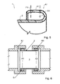
- FIG. 5 shows a detailed view of the connector 1 from the Figures 1-4 , FIG. 5 shows in particular the first end section A1, whereby the second end section A2 can be identical.
- FIG. 5 can be taken in particular that the contact surface K1 is convexly curved, in particular spherical or substantially spherical.
- the fact that the contact surfaces K1 and K2 are convexly curved it can be ensured that the contact surfaces K1 and K2 and the tube ends of the two tubes R1 and R2 can roll virtually together and thus cause relative movements to no leakage.
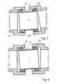
- FIG. 6 shows a sectional view of the connector 1 from FIG. 1 in assembled condition.
- a comparison of FIGS. 1 and 6 shows that despite an axial displacement of the two tubes R1 and R2, the connector 1 securely and sealingly abuts the tube ends of the two tubes R1 and R2.
- FIG. 7 shows a sectional view of the connector 1 from FIG. 1 in assembled condition. Out FIG. 7 It will be seen that, despite angular misalignment or angular misalignment of the two tubes R1 and R2, the connector 1 will securely and sealingly abut the tube ends of the two tubes R1 and R2.
- FIG. 8 shows a sectional view of the connector 1 from FIG. 1 in assembled condition. Out FIG. 8 It can be seen that despite an axial offset of the two tubes R1 and R2, the connecting piece 1 securely and sealingly abuts the tube ends of the two tubes R1 and R2.
- FIG. 9 shows a sectional view of a connector 1 according to another embodiment of the invention. A peculiarity of in FIG. 9 is shown that the flange portions F1 and F2 are not integrally formed integrally with the intermediate portion Z, but are mounted to the intermediate portion Z, for example, welded or glued.
- FIG. 10 shows a sectional view of a connector 1 according to another embodiment of the invention.
- the flange portions F1 and F2 are not integrally formed integrally with the intermediate portion Z, but mounted on the intermediate portion Z, so materially connected (eg welded or glued) or positively connected (eg riveted or screwed) in the region of connection surfaces.
- FIG. 10 a variant of the connecting piece 1 according to the invention with to the free ends of the connecting piece open towards flange portion F1, F2, so that in the installed state, the medium flowing through the connecting piece also enters the annular spaces S1 and S2.
- the connector 1 may be provided with a preferably galvanic coating and the coating may comprise: a matrix phase comprising a metal or a metal alloy, and MCrAlY particles dispersed in the matrix, selected from M. Nickel, cobalt, iron yttrium, aluminum or a combination of two or more thereof.
Landscapes
- Engineering & Computer Science (AREA)
- General Engineering & Computer Science (AREA)
- Mechanical Engineering (AREA)
- Chemical & Material Sciences (AREA)
- Combustion & Propulsion (AREA)
- Quick-Acting Or Multi-Walled Pipe Joints (AREA)
Abstract
Description
- Die Erfindung betrifft ein zweckmäßig rohrförmiges Verbindungsstück zum Verbinden der Rohrenden zweier fluidführender Rohre, insbesondere motorabgasführender Rohre. Das Verbindungsstück findet insbesondere Anwendung in Rohranordnungen, z. B. Abgasträkten oder Abgasnachbehandlungssystemen, für Verbrennungsmotoren, z. B. von Fahrzeugen (wie etwa Kraftfahrzeuge, Nutzfahrzeuge, Baustellenfahrzeuge, Land- oder Agrarmaschinen, Schienenfahrzeuge, etc.), oder bei Aggregaten zur Stromerzeugung oder anderen Industrie- oder Baumaschinenaggregaten.
- Aus der
EP 2 273 175 B1 ist eine thermisch dehnbare Dichtverbindung aus einem einstückigen, rohrförmigen Körper bekannt. Der rohrförmige Körper dient dazu, die Rohrenden zweier motorabgasführender Rohre eines Kraftfahrzeugs miteinander zu verbinden. Der rohrförmige Körper und die zwei Rohre führen im Betrieb Abgas mit den bekannt hohen Temperaturen. Die Materialstärke des rohrförmigen Körpers ist geringer als die Materialstärke der Rohrenden der zwei Rohre. Bei einer Änderung der Abgastemperatur können durch die unterschiedlichen Materialstärken an den Kontaktflächen zwischen dem rohrförmigen Körper und den Rohrenden der zwei Rohre im Betrieb sehr hohe Temperaturdifferenzen entstehen. Die hohen Temperaturdifferenzen können hohe thermische Spannungen zur Folge haben, die im Extremfall zu plastischen Verformungen des Verbindungsstücks und in der Folge zu Undichtigkeiten führen können. - Eine Aufgabe der Erfindung ist es, ein verbessertes und/oder alternatives Verbindungsstück zum Verbinden der Rohrenden zweier fluidführender Rohre zu schaffen.
- Die Erfindung schafft ein Verbindungsstück zum Verbinden der Rohrenden zweier fluidführender Rohre, vorzugsweise einer Rohranordnung (z. B. für einen Abgastrakt oder ein Abgasnachbehandlungssystem) für einen Verbrennungsmotor für ein Fahrzeug, z. B. ein Kraftfahrzeug, ein Baustellenfahrzeug, eine Land- oder Agrarmaschine, ein Schienenfahrzeug, ein Nutzfahrzeug, insbesondere ein Lastkraftwagen oder ein Omnibus, etc., allerdings ebenso für ein Aggregat zur Stromerzeugung.
- Das Verbindungsstück umfasst einen ersten axialen Endabschnitt, einen zweiten axialen Endabschnitt und einen sich zwischen dem ersten Endabschnitt und dem zweiten Endabschnitt erstreckenden Zwischenabschnitt.
- Das Verbindungsstück zeichnet sich insbesondere dadurch aus, dass der erste Endabschnitt und/oder der zweite Endabschnitt einen Flanschabschnitt mit einer Kontaktfläche zur Kopplung an ein Rohrende umfasst. Der Flanschabschnitt ist von dem Zwischenabschnitt in Radialrichtung des Verbindungsstücks beabstandet, zweckmäßig zur thermischen Entkopplung oder Isolierung (insbesondere der Kontaktfläche(n)) von den fluidführenden Teilen des Verbindungsstücks (insbesondere des Zwischenabschnitts). Dadurch kann zweckmäßig ermöglicht werden, dass die Temperatur des Verbindungsstücks an der Kontaktstelle zum Rohrende eher durch die Temperatur des Rohrendes bestimmt wird und/oder durch die Bereiche des Verbindungsstücks bestimmt wird, die nicht direkt mit dem geführten Fluid beaufschlagt werden. Die eingangs in Bezug auf den Stand der Technik erwähnten hohen Temperaturdifferenzen können somit zweckmäßig vermieden oder zumindest reduziert werden.
- Bei einer besonders bevorzugten Ausführungsform ist es möglich, dass der erste Endabschnitt einen Flanschabschnitt mit einer Kontaktfläche zur Kopplung an das eine Rohrende umfasst und der zweite Endabschnitt einen Flanschabschnitt mit einer Kontaktfläche zur Kopplung an das andere Rohrende umfasst und die Flanschabschnitte von dem Zwischenabschnitt radial beabstandet sind.
- Nachfolgend wird die Erfindung in Bezug auf zwei Flanschabschnitte beschrieben. Es sei allerdings erwähnt, dass im Rahmen der Erfindung nur ein Flanschabschnitt vorgesehen sein kann und die folgende Beschreibung somit sinngemäß auch für nur einen Flanschabschnitt gilt.
- Es ist möglich, dass die Flanschabschnitte mit dem Zwischenabschnitt Zwischenräume bilden. Die Zwischenräume dienen zweckmäßig dazu, die Flanschabschnitte, insbesondere deren Kontaktflächen, thermisch von den fluidführenden Bereichen des Verbindungsstücks und/oder der zwei Rohre zu isolieren oder zu entkoppeln. Die Zwischenräume können z. B. luftgefüllt sein oder aber mit einem isolierenden Material gefüllt sein.
- Es ist möglich, dass die Flanschabschnitte und/oder die Zwischenräume von den fluidführenden Bereichen des Verbindungsstücks und/oder der zwei Rohre fluidisch separiert sind.
- Ferner können die Zwischenräume zur Umgebungsluft außerhalb des Verbindungsstücks hin offen sein, so dass die Flanschabschnitte, insbesondere deren Kontaktfläche, über die Zwischenräume durch Umgebungsluft kühlbar sind. Die Flanschabschnitte, insbesondere deren Kontaktflächen, sind somit zweckmäßig umgebungsluftkühlbar.
- Es ist möglich, dass die Flanschabschnitte umlaufend ausgeführt sind.
- Die Zwischenräume sind vorzugsweise als Ringräume ausgeführt.
- Die Flanschabschnitte und das Zwischenstück können insbesondere einstückig und/oder integral ausgeführt sein und somit aus einem Stück hergestellt sein. Die Flanschabschnitte sind vorzugsweise umgebogen oder umgekantet ausgeführt.
- Allerdings ist es ebenso möglich, dass die Flanschabschnitte an den Zwischenabschnitt montiert sind, z.B. an den Zwischenabschnitt geschweißt, geklebt oder durch andere Festmachtechniken festgemacht sind.
- Die Flanschabschnitte sind vorzugsweise elastisch ausgeführt, weisen insbesondere eine Federwirkung auf. Dadurch kann insbesondere eine Steck- und/oder Klemmverbindung mit den Rohrenden erzielt werden.
- Die Flanschabschnitte sind vorzugsweise in Axialrichtung des Verbindungsstücks voneinander beabstandet.
- Es ist möglich, dass die Flanschabschnitte den Zwischenabschnitt in Axialrichtung des Verbindungsstücks überlappen oder übergreifen.
- Es ist möglich, dass die Zwischenräume in Axialrichtung des Verbindungsstücks nach innen offen sind, vorzugsweise ansonsten aber durch das Verbindungsstück begrenzt werden.
- Die Flanschabschnitte sind von dem Zwischenstück vorzugsweise in Radialrichtung des Verbindungsstücks nach außen beabstandet und weisen somit vorzugsweise einen größeren Radius auf als der Zwischenabschnitt.
- Die Kontaktfläche des Flanschabschnitts des ersten Endabschnitts und/oder die Kontaktfläche des Flanschabschnitts des zweiten Endabschnitts ist vorzugsweise konvex und/oder gekrümmt ausgebildet, insbesondere sphärisch (z. B. kugelförmig). Dadurch können Montagetoleranzen und Temperaturdehnungen, die z. B. zu Winkelfehlern und/oder Achsversätzen führen, ausgeglichen werden. Der Radius der Kontaktflächen des Verbindungsstücks entspricht zweckmäßig dem Radius der zylindrischen Kontaktflächen der Rohrenden der zwei Rohre. Die Ausführung des Verbindungsstücks als Steckstück ermöglicht zudem einen Ausgleich von Temperaturdehnungen und Montagetoleranzen in Axialrichtung des Verbindungsstücks.
- Die Kontaktfläche des Flanschabschnitts des ersten Endabschnitts und/oder die Kontaktfläche des Flanschabschnitts des zweiten Endabschnitts kann mit einer verschleißbeständigen Beschichtung versehen sein.
- Das Verbindungsstück ist vorzugsweise rohrförmig ausgeführt und/oder als Steckstück, insbesondere zum Einstecken in die Rohrenden der zwei Rohre.
- Es ist möglich, dass das Verbindungsstück mit einer z.B. galvanischen Beschichtung versehen ist. Die Beschichtung kann insbesondere folgendes umfassen:
- eine Matrix-Phase, aufweisend ein Metall oder eine Legierung,
- MCrAlY-Partikel, dispergiert in der Matrix, wobei M ausgewählt wird aus der Gruppe umfassend Chrom, Aluminium, Yttrium, Nickel, Kobalt, Eisen oder einer Kombination von zwei oder mehr als zwei davon.
- Das Verbindungsstück kann z. B. eine ausscheidungshärtbare Legierung aufweisen oder daraus hergestellt sein, z. B. rostfreien Stahl oder Edelstahl, vorzugsweise ausgewählt aus: 17-7 PH, PH 15-7, PH 14-8 Mo, AM-350 und/oder AM-355.
- Zu erwähnen ist, dass das im Rahmen der Erfindung erwähnte "Fluid" vorzugsweise ein "Gas" ist, insbesondere ein "Motorabgas", z. B. aus einem Verbrennungsmotor. Die Erfindung ist nicht auf ein Verbindungsstück beschränkt, sondern umfasst auch eine Rohranordnung für einen Verbrennungsmotor, z. B. einen Abgastrakt und/oder ein Abgasnachbehandlungssystem. Die Rohranordnung umfasst ein erstes Rohr, ein zweites Rohr und ein Verbindungsstück, das die zwei Rohrenden des ersten Rohrs und des zweiten Rohrs miteinander verbindet und zweckmäßig wie hierin offenbart ausgeführt ist.
- Es ist möglich, dass das Verbindungsstück zwischen den Rohrenden der zwei Rohre zur Umgebungsluft außerhalb des Verbindungsstücks und/oder außerhalb der zwei Rohrenden hin vorzugsweise so frei liegt, dass es durch die Umgebungsluft beaufschlagt, insbesondere gekühlt werden kann.
- Darüber hinaus betrifft die Erfindung ein Fahrzeug, vorzugsweise ein Kraftfahrzeug, ein Nutzfahrzeug, z. B. einen Omnibus oder einen Lastkraftwagen, ein Baustellenfahrzeug, eine Land- oder Agrarmaschine, ein Schienenfahrzeug, etc., oder ein Aggregat zur Stromerzeugung, mit einem Verbindungsstück und/oder einer Rohranordnung, wie hierin beschrieben.
- In einer weiteren bevorzugten, alternativen Ausführungsform sind die Endabschnitte A1, A2 derart ausgestaltet, dass die Flanschabschnitte F1, F2 bzw. deren Innenräume also die Zwischenräume S1, S2 zu den freien Enden des Verbindungsstücks hin offen sind. Die stoffschlüssige oder formschlüssige Verbindung der die Flanschabschnitte bildenden Elemente mit dem zylindrischen Grundkörper des Verbindungsstücks kann dabei vorzugsweise am nach innen gerichteten Bereich der beiden Flanschabschnitte erfolgen. Dies hat den Vorteil, dass damit die Gesamtlänge des Verbindungsstücks minimiert werden kann. Dies ist darin begründet, dass der maximale Durchmesser des Verbindungsstücks (also im Bereich der Flanschabschnitte) möglichst an den äußeren Randbereichen des Verbindungsstücks angeordnet sein soll und zugleich eine Anbindungsfläche zwischen der den Flanschabschnitt bildenden Elemente und dem zylindrischen Grundkörper vorgehalten werden muss. Wenn nun diese Anbindungsfläche im axial inneren Bereich des Verbindungsstücks liegt, kann folglich der den maximalen Durchmesser bildende Bereich der Flanschflächen weiter außerhalb (axialer Endbereich des Verbindungsstücks) angeordnet werden. Schließlich ist damit nicht nur eine Reduzierung der Gesamtlänge des Verbindungsstück möglich, sondern alternativ kann auch bei gleichbleibender Gesamtlänge des Verbindungsstücks die Axialfehler- und/oder Winkelfehlertolerierbarkeit der zu verbindenden Rohrenden erhöht werden. Ferner ergibt sich durch die Anordnung der Anbindungsflächen der Flanschabschnitte in den axial zentrumsnäheren Bereich der Verbindungsstücke, dass der Zwischenraum und/oder der Flanschabschnitt mit den fluidführenden Bereichen des Verbindungsstücks (1) fluidisch verbunden ist.
- Die zuvor beschriebenen bevorzugten Ausführungsformen und Merkmale der Erfindung sind beliebig miteinander kombinierbar. Andere vorteilhafte Weiterbildungen der Erfindung sind in den Unteransprüchen offenbart oder ergeben sich aus der nachstehenden Beschreibung bevorzugter Ausführungsformen der Erfindung in Verbindung mit den beigefügten Figuren.
- Figur 1
- zeigt eine Schnittansicht eines Verbindungsstücks im montierten Zustand gemäß einer Ausführungsform der Erfindung,
- Figur 2
- zeigt eine Vorderansicht des Verbindungsstücks aus
Figur 1 , - Figur 3
- zeigt eine Seitenansicht des Verbindungsstücks aus den
Figuren 1 und2 , - Figur 4
- zeigt eine perspektivische Ansicht des Verbindungsstücks aus den
Figuren 1-3 , - Figur 5
- zeigt eine Detailansicht eines erfindungsgemäßen Verbindungsstücks,
- Figur 6
- zeigt eine Schnittansicht des Verbindungsstücks aus
Figur 1 im montierten Zustand nach einer Axialverschiebung, - Figur 7
- zeigt eine Schnittansicht des Verbindungsstücks aus
Figur 1 im montierten Zustand nach einem Winkelversatz, - Figur 8
- zeigt eine Schnittansicht des Verbindungsstücks aus
Figur 1 im montierten Zustand nach einem Achsversatz, - Figur 9
- zeigt eine Schnittansicht eines Verbindungsstücks gemäß einer anderen Ausführungsform der Erfindung, und
- Figur 10.
- Zeigt eine Schnittansicht eines Verbindungsstücks gemäß einer weiteren Ausführungsform der Erfindung.
- Die in den Figuren gezeigten Ausführungsformen stimmen teilweise überein, wobei ähnliche oder identische Teile mit den gleichen Bezugszeichen versehen sind und zu deren Erläuterung auch auf die Beschreibung der anderen Ausführungsform verwiesen wird, um Wiederholungen zu vermeiden.
-
Figur 1 zeigt eine Schnittansicht eines Verbindungsstücks 1 im montierten Zustand. Das Verbindungsstück 1 dient zum Verbinden der Rohrenden zweier Rohre R1 und R2 z. B. einer einem Verbrennungsmotor nachgeschalteten Rohranordnung. Das Verbindungsstück 1 und die zwei Rohre R1 und R2 dienen somit insbesondere zur Motorabgasführung. - Nachfolgend wir das Verbindungsstück 1 unter Bezugnahme auf die
Figuren 1 bis 4 beschrieben. - Das Verbindungsstück 1 umfasst einen ersten axialen Endabschnitt A1, einen zweiten axialen Endabschnitt A2 und einen sich zwischen dem ersten Endabschnitt A1 und dem zweiten Endabschnitt A2 erstreckenden Zwischenabschnitt Z. Der erste Endabschnitt A1 umfasst einen Flanschabschnitt F1 mit einer Kontaktfläche K1 zur Kopplung an das eine Rohrende. Der zweite Endabschnitt A2 umfasst einen Flanschabschnitt F2 mit einer Kontaktfläche K2 zur Kopplung an das andere Rohrende.
- Die Flanschabschnitte F1 und F2 sind in Axialrichtung a des Verbindungsstücks 1 voneinander beabstandet und überlappen oder übergreifen den Zwischenabschnitt Z. Die Flanschabschnitte F1 und F2 sind von dem Zwischenstück Z in Radialrichtung r des Verbindungsstücks 1 zweckmäßig nach außen beabstandet und bilden mit dem Zwischenabschnitt Z ringförmige Zwischenräume S1 und S2. Die Zwischenräume S1 und S2 sind zur Umgebungsluft außerhalb des Verbindungsstücks 1 hin offen und von den motorabgasführenden Bereichen des Verbindungsstücks 1 fluidisch entkoppelt. Die Zwischenräume S1 und S2 stellen somit Isolationsräume zwischen den relativ heißen motorabgasführenden Bereichen des Verbindungsstücks 1 und den Flanschabschnitten F1 und F2, insbesondere den Kontaktflächen K1 und K2 dar. Dadurch treten an den für die Dichtigkeit zuständigen Kontaktstellen zwischen dem Verbindungsstück 1 und den zwei Rohren R1 und R2 nur geringe Temperaturschwankungen auf. Insbesondere wird die Temperatur des Verbindungsstücks 1 an den Kontaktflächen K1 und K2 zu den Rohrenden der zwei Rohre R1 und R2 relativ stark durch die Temperatur der Rohrenden selbst bestimmt.
- Die Flanschabschnitte F1 und F2 und der Zwischenabschnitt Z sind einstückig integral ausgeführt, so dass das Verbindungsstück 1 quasi aus einem einzigen integralen Stück hergestellt ist. Die Flanschabschnitte F1 und F2 können hierbei auf einfache Weise ausgehend von dem Zwischenabschnitt Z umgebogen oder umgekantet werden.
- Die Flanschabschnitte F1 und F2 sind elastisch ausgeführt und weisen eine Federwirkung auf, um im montierten Zustand gegen die Rohrenden der zwei Rohre R1 und R2 zu drücken.
-
Figur 1 kann ferner entnommen werden, dass das Verbindungsstück 1 zwischen den Rohrenden der zwei Rohre R1 und R2 zur Umgebungsluft außerhalb des Verbindungsstücks 1 und außerhalb der Rohrenden der zwei Rohre R1, R2 hin frei liegt und somit durch die Umgebungsluft kühlbar ist. -
Figur 5 zeigt eine Detailansicht des Verbindungsstücks 1 aus denFiguren 1-4 . Figur 5 zeigt insbesondere den ersten Endabschnitt A1, wobei der zweite Endabschnitt A2 identisch ausgeführt sein kann. - Aus
Figur 5 kann insbesondere entnommen werden, dass die Kontaktfläche K1 konvex gekrümmt ausgebildet ist, insbesondere sphärisch oder im Wesentlichen kugelförmig. Dadurch, dass die Kontaktflächen K1 und K2 konvex gekrümmt ausgebildet sind, kann gewährleistet werden, dass die Kontaktflächen K1 und K2 und die Rohrenden der zwei Rohre R1 und R2 quasi aneinander abrollen können und somit Relativbewegungen zu keiner Undichtigkeit führen. -
Figur 6 zeigt eine Schnittansicht des Verbindungsstücks 1 ausFigur 1 in montiertem Zustand. Ein Vergleich derFiguren 1 und6 zeigt, dass trotz einer Axialverschiebung der zwei Rohre R1 und R2 das Verbindungsstück 1 sicher und dichtend an den Rohrenden der zwei Rohre R1 und R2 anliegt. -
Figur 7 zeigt eine Schnittansicht des Verbindungsstücks 1 ausFigur 1 in montiertem Zustand. AusFigur 7 wird ersichtlich, dass trotz eines Winkelversatzes oder eines Winkelfehlers der zwei Rohre R1 und R2 das Verbindungsstück 1 sicher und dichtend an den Rohrenden der zwei Rohren R1 und R2 anliegt. -
Figur 8 zeigt eine Schnittansicht des Verbindungsstücks 1 ausFigur 1 in montiertem Zustand. AusFigur 8 wird ersichtlich, dass trotz eines Achsversatzes der zwei Rohre R1 und R2 das Verbindungsstück 1 sicher und dichtend an den Rohrenden der zwei Rohre R1 und R2 anliegt. -
Figur 9 zeigt eine Schnittansicht eines Verbindungsstücks 1 gemäß einer anderen Ausführungsform der Erfindung. Eine Besonderheit des inFigur 9 gezeigten Verbindungsstücks 1 ist, dass die Flanschabschnitte F1 und F2 nicht integral einstückig mit dem Zwischenabschnitt Z ausgebildet sind, sondern an den Zwischenabschnitt Z montiert sind, z.B. angeschweißt oder angeklebt sind. -
Figur 10 zeigt eine Schnittansicht eines Verbindungsstücks 1 gemäß einer weiteren Ausführungsform der Erfindung. Wie in der inFigur 9 dargestellten Ausführung sind die Flanschabschnitte F1 und F2 nicht integral einstückig mit dem Zwischenabschnitt Z ausgebildet, sondern an den Zwischenabschnitt Z montiert, also stoffschlüssig (z.B. angeschweißt oder angeklebt) oder formschlüssig (z.B. angenietet oder angeschraubt) im Bereich von Anbindungsflächen verbunden. Auch zeigt dieFigur 10 eine Variante des erfindungsgemäßen Verbindungsstücks 1 mit zu den freien Enden des Verbindungsstück hin offenen Flanschabschnitt F1, F2 aufweist, so dass im verbauten Zustand das das Verbindungsstück durchströmende Medium auch in die ringförmigen Zwischenräume S1 und S2 gelangt. - Zu erwähnen ist noch, dass das Verbindungsstück 1 mit einer vorzugsweise galvanischen Beschichtung versehen sein kann und die Beschichtung folgendes umfassen kann: eine Matrix-Phase, aufweisend ein Metall oder eine Metalllegierung, und MCrAlY-Partikel, dispergiert in der Matrix, mit M ausgewählt aus Nickel, Kobalt, Eisen Yttrium, Aluminium oder einer Kombination von zwei oder mehr davon.
- Die Erfindung ist nicht auf die, oben beschriebenen bevorzugten Ausführungsformen beschränkt. Vielmehr ist eine Vielzahl von Varianten und Abwandlungen möglich, die ebenfalls von dem Erfindungsgedanken Gebrauch machen und deshalb in den Schutzbereich fallen. Darüber hinaus beansprucht die Erfindung auch Schutz für den Gegenstand und die Merkmale der Unteransprüche unabhängig von den in Bezug genommenen Merkmalen und Ansprüchen.
-
- 1
- Verbindungsstück
- R1
- erstes Rohr
- R2
- zweites Rohr
- A1
- erster axialer Endabschnitt
- A2
- zweiter axialer Endabschnitt
- F1
- erster Flanschabschnitt
- F2
- zweiter Flanschabschnitt
- K1
- erste Kontaktfläche
- K2
- zweite Kontaktfläche
- Z
- Zwischenabschnitt
- S1
- erster Zwischenraum
- S2
- zweiter Zwischenraum
- a
- Axialrichtung des Verbindungsstücks
- r
- Radialrichtung des Verbindungsstücks
Claims (16)
- Verbindungsstück (1) zum Verbinden der Rohrenden zweier fluidführender Rohre (R1, R2), mit einem ersten axialen Endabschnitt (A1), einem zweiten axialen Endabschnitt (A2) und einem sich zwischen dem ersten Endabschnitt (A1) und dem zweiten Endabschnitt (A2) erstreckenden Zwischenabschnitt (Z), dadurch gekennzeichnet, dass der erste Endabschnitt (A1) und/oder der zweite Endabschnitt (A2) einen Flanschabschnitt (F1, F2) mit einer Kontaktfläche (K1, K2) zur Kopplung an ein Rohrende umfasst und der Flanschabschnitt (F1, F2) von dem Zwischenabschnitt (Z) radial beabstandet ist.
- Verbindungsstück (1) nach Anspruch 1, dadurch gekennzeichnet, dass der Flanschabschnitt (F1, F2) mit dem Zwischenabschnitt (Z) einen Zwischenraum (S1, S2) bildet, wobei vorzugsweise der Zwischenraum (S1, S2) als Ringraum ausgeführt ist.
- Verbindungsstück (1) nach Anspruch 2, dadurch gekennzeichnet, dass der Zwischenraum (S1, S2) und/oder der Flanschabschnitt (F1, F2) von den fluidführenden Bereichen des Verbindungsstücks (1) fluidisch separiert ist.
- Verbindungsstück (1) nach Anspruch 2 oder 3, dadurch gekennzeichnet, dass der Zwischenraum (S1, S2) zur Umbebungsluft außerhalb des Verbindungsstücks (1) hin offen ist.
- Verbindungsstück (1) nach einem der vorhergehenden Ansprüche, dadurch gekennzeichnet, dass der Flanschabschnitt (F1, F2) als umgebogener oder umgekanteter Flanschabschnitt (F1, F2) ausgeführt ist und/oder der Flanschabschnitt (F1, F2) an den Zwischenabschnitt (Z) montiert ist.
- Verbindungsstück (1) nach einem der vorhergehenden Ansprüche, dadurch gekennzeichnet, dass der Flanschabschnitt (F1, F2) und der Zwischenabschnitt (Z) einstückig integral ausgeführt sind und/oder der Flanschabschnitt (F1, F2) elastisch ausgeführt ist, insbesondere eine Federwirkung aufweist.
- Verbindungsstück (1) nach einem der vorhergehenden Ansprüche, dadurch gekennzeichnet, dass Verbindungsstück (1) nach einem der Ansprüche 2 bis 10, dadurch gekennzeichnet, dass der Zwischenraum (S1, S2) in Axialrichtung des Verbindungsstücks (1) einwärts offen ist und vorzugsweise ansonsten durch das Verbindungsstück (1) begrenzt ist.
- Verbindungsstück (1) nach einem der vorhergehenden Ansprüche, dadurch gekennzeichnet, dass der Flanschabschnitt (F1, F2) von dem Zwischenabschnitt (Z) nach radial außen beabstandet ist und somit einen größeren Radius aufweist als der Zwischenabschnitt (Z) und/oder der Flanschabschnitt (F1, F2) den Zwischenabschnitt (Z) überlappt oder übergreift.
- Verbindungsstück (1) nach einem der vorhergehenden Ansprüche, dadurch gekennzeichnet, dass die Kontaktfläche (K1, K2) des Flanschabschnitts (F1, F2) konvex gekrümmt ausgebildet ist und/oder die Kontaktfläche (K1, K2) des Flanschabschnitts (F1, F2) sphärisch ausgebildet ist.
- Verbindungsstück (1) nach einem der vorhergehenden Ansprüche, dadurch gekennzeichnet, dass die Kontaktfläche (K1, K2) des Flanschabschnitts (F1, F2) mit einer verschleißbeständigen Beschichtung versehen ist.
- Verbindungsstück (1) nach einem der vorhergehenden Ansprüche, dadurch gekennzeichnet, dass das Verbindungsstück (1) rohrförmig und/oder als Steckstück zum Einstecken in die Rohrenden der zwei Rohre (R1, R2) ausgeführt ist.
- Verbindungsstück (1) nach einem der vorhergehenden Ansprüche, dadurch gekennzeichnet, dass das Verbindungsstück (1) mit einer vorzugsweise galvanischen Beschichtung versehen ist und die Beschichtung folgendes umfasst:- eine Matrix-Phase, aufweisend ein Metall oder eine Metalllegierung,- MCrAlY-Partikel, dispergiert in der Matrix, wobei M ausgewählt wird aus Nickel, Kobalt, Eisen, Chrom, Yttrium, Aluminium oder einer Kombination von zwei oder mehr als zwei davon.
- Verbindungsstück (1) nach einem der vorhergehenden Ansprüche, dadurch gekennzeichnet, dass der erste Endabschnitt (A1) einen Flanschabschnitt (F1) mit einer Kontaktfläche (K1) zur Kopplung an das eine Rohrende umfasst und der zweite Endabschnitt (A2) einen Flanschabschnitt (F2) mit einer Kontaktfläche (K2) zur Kopplung an das andere Rohrende umfasst und die Flanschabschnitte (F1, F2) von dem Zwischenabschnitt (Z) radial beabstandet sind.
- Verbindungsstück (1) nach Anspruch 2, dadurch gekennzeichnet, dass der Zwischenraum (S1, S2) und/oder der Flanschabschnitt (F1, F2) mit den fluidführenden Bereichen des Verbindungsstücks (1) fluidisch verbunden ist.
- Rohranordnung, insbesondere Abgastrakt oder Abgasnachbehandlungssystem, für einen Verbrennungsmotor, mit einem ersten Rohr (R1), einem zweiten Rohr (R2) und einem Verbindungsstück (1), das die zwei Rohrenden des ersten Rohrs (R1) und des zweiten Rohrs (R2) miteinander verbindet, dadurch gekennzeichnet, dass das Verbindungsstück (1) gemäß einem der vorhergehenden Ansprüche ausgebildet ist, wobei vorzugsweise das Verbindungsstück (1) zwischen den Rohrenden der zwei Rohre (R1, R2) zur Umgebungsluft außerhalb des Verbindungsstücks (1) und außerhalb der zwei Rohrenden hin frei liegt.
- Fahrzeug oder Aggregat zur Stromerzeugung, mit einem Verbindungsstück (1) gemäß einem der Ansprüche 1 bis 14 oder einer Rohranordnung gemäß Anspruch 15.
Priority Applications (1)
| Application Number | Priority Date | Filing Date | Title |
|---|---|---|---|
| EP14004006.4A EP3026317B1 (de) | 2014-11-27 | 2014-11-27 | Verbindungsstück für fluidführende Rohre |
Applications Claiming Priority (1)
| Application Number | Priority Date | Filing Date | Title |
|---|---|---|---|
| EP14004006.4A EP3026317B1 (de) | 2014-11-27 | 2014-11-27 | Verbindungsstück für fluidführende Rohre |
Publications (2)
| Publication Number | Publication Date |
|---|---|
| EP3026317A1 true EP3026317A1 (de) | 2016-06-01 |
| EP3026317B1 EP3026317B1 (de) | 2018-10-03 |
Family
ID=52010999
Family Applications (1)
| Application Number | Title | Priority Date | Filing Date |
|---|---|---|---|
| EP14004006.4A Active EP3026317B1 (de) | 2014-11-27 | 2014-11-27 | Verbindungsstück für fluidführende Rohre |
Country Status (1)
| Country | Link |
|---|---|
| EP (1) | EP3026317B1 (de) |
Citations (6)
| Publication number | Priority date | Publication date | Assignee | Title |
|---|---|---|---|---|
| DE3009645A1 (de) * | 1980-03-13 | 1981-09-24 | Klöckner-Humboldt-Deutz AG, 5000 Köln | Rohrverbindung |
| US4613170A (en) * | 1984-12-20 | 1986-09-23 | Nelson Industries, Inc. | Adaptor for connecting tubular members in an exhaust system |
| US6220605B1 (en) * | 1998-07-14 | 2001-04-24 | Caterpillar Inc. | Slip joint connection for engine exhaust system |
| US20070284828A1 (en) * | 2004-09-30 | 2007-12-13 | Kei Komukai | Seal Part |
| US20090033088A1 (en) * | 2007-07-31 | 2009-02-05 | Eaton Corporation | Rotomold bead |
| EP2273175A1 (de) * | 2009-07-08 | 2011-01-12 | Parker-Hannifin Corporation | Dichtungsverbindung zum Anschließen von Rohrteilen in einem Motorabgassystem |
-
2014
- 2014-11-27 EP EP14004006.4A patent/EP3026317B1/de active Active
Patent Citations (7)
| Publication number | Priority date | Publication date | Assignee | Title |
|---|---|---|---|---|
| DE3009645A1 (de) * | 1980-03-13 | 1981-09-24 | Klöckner-Humboldt-Deutz AG, 5000 Köln | Rohrverbindung |
| US4613170A (en) * | 1984-12-20 | 1986-09-23 | Nelson Industries, Inc. | Adaptor for connecting tubular members in an exhaust system |
| US6220605B1 (en) * | 1998-07-14 | 2001-04-24 | Caterpillar Inc. | Slip joint connection for engine exhaust system |
| US20070284828A1 (en) * | 2004-09-30 | 2007-12-13 | Kei Komukai | Seal Part |
| US20090033088A1 (en) * | 2007-07-31 | 2009-02-05 | Eaton Corporation | Rotomold bead |
| EP2273175A1 (de) * | 2009-07-08 | 2011-01-12 | Parker-Hannifin Corporation | Dichtungsverbindung zum Anschließen von Rohrteilen in einem Motorabgassystem |
| EP2273175B1 (de) | 2009-07-08 | 2012-03-14 | Parker-Hannifin Corporation | Dichtungsverbindung zum Anschließen von Rohrteilen in einem Motorabgassystem |
Also Published As
| Publication number | Publication date |
|---|---|
| EP3026317B1 (de) | 2018-10-03 |
Similar Documents
| Publication | Publication Date | Title |
|---|---|---|
| DE102009042260B4 (de) | Abgasturbolader | |
| EP2388455B1 (de) | Abgasturbolader | |
| EP2180163B1 (de) | Turbinengehäuse und Verfahren zu seiner Herstellung | |
| DE102011050506B4 (de) | Abgasturbolader | |
| EP1998017B1 (de) | Abgaswärmetauscher | |
| DE102009025054A1 (de) | Turbinengehäuse | |
| DE102010022218A1 (de) | Abgasturbolader | |
| DE202008010025U1 (de) | Metallische Dichtung, insbesondere Abgaskrümmerdichtung | |
| DE102014202466A1 (de) | Ladeluftkühler für eine Frischluftanlage einer Brennkraftmaschine | |
| EP2807350B1 (de) | Dichtung für eine einrichtung zum nachbehandeln von abgasen einer brennkraftmaschine | |
| EP3034979B1 (de) | Abgaswärmeübertrager | |
| EP3516319B1 (de) | Wärmetauscher | |
| DE102013210982A1 (de) | Dehnkörper zur Verbindung von zwei Rohrstücken insbesondere eines Abgaskanals eines Kraftfahrzeugs sowie Abgasturboladereinheit mit einem derartigen Dehnkörper | |
| EP1895120B1 (de) | Gehäuse für eine Abgasreinigungskomponente zur Ausbildung einer Fügeverbindung mit einem Abgasleitungsabschnitt | |
| EP2871397B1 (de) | Anordnung zur Verbindung zweier Rohrenden, insbesondere in einem Abgasstrang einer Brennkraftmaschine | |
| EP3026317B1 (de) | Verbindungsstück für fluidführende Rohre | |
| EP2711659A2 (de) | Verfahren zur Herstellung eines Wärmetauschers | |
| DE102014011606B4 (de) | Abgassystem für eine Brennkraftmaschine | |
| DE102014000785A1 (de) | Verbindungsstück für fluidführende Rohre | |
| EP1248027A1 (de) | Vorrichtung zum axialen Verbinden zweier rohrartiger Bauteile | |
| EP2894312B1 (de) | Flexibles Leitungselement mit Isolierung | |
| DE102004051680B4 (de) | Anordnung zur Befestigung eines Abgaskrümmers | |
| DE102009043117A1 (de) | Dichtungsanordnung | |
| DE102012216097B4 (de) | Entkoppelelement | |
| DE10220986B4 (de) | Abgaskrümmer und ein Verfahren zu dessen Herstellung |
Legal Events
| Date | Code | Title | Description |
|---|---|---|---|
| PUAI | Public reference made under article 153(3) epc to a published international application that has entered the european phase |
Free format text: ORIGINAL CODE: 0009012 |
|
| AK | Designated contracting states |
Kind code of ref document: A1 Designated state(s): AL AT BE BG CH CY CZ DE DK EE ES FI FR GB GR HR HU IE IS IT LI LT LU LV MC MK MT NL NO PL PT RO RS SE SI SK SM TR |
|
| AX | Request for extension of the european patent |
Extension state: BA ME |
|
| STAA | Information on the status of an ep patent application or granted ep patent |
Free format text: STATUS: REQUEST FOR EXAMINATION WAS MADE |
|
| 17P | Request for examination filed |
Effective date: 20161128 |
|
| GRAP | Despatch of communication of intention to grant a patent |
Free format text: ORIGINAL CODE: EPIDOSNIGR1 |
|
| STAA | Information on the status of an ep patent application or granted ep patent |
Free format text: STATUS: GRANT OF PATENT IS INTENDED |
|
| INTG | Intention to grant announced |
Effective date: 20180507 |
|
| GRAS | Grant fee paid |
Free format text: ORIGINAL CODE: EPIDOSNIGR3 |
|
| GRAA | (expected) grant |
Free format text: ORIGINAL CODE: 0009210 |
|
| STAA | Information on the status of an ep patent application or granted ep patent |
Free format text: STATUS: THE PATENT HAS BEEN GRANTED |
|
| AK | Designated contracting states |
Kind code of ref document: B1 Designated state(s): AL AT BE BG CH CY CZ DE DK EE ES FI FR GB GR HR HU IE IS IT LI LT LU LV MC MK MT NL NO PL PT RO RS SE SI SK SM TR |
|
| REG | Reference to a national code |
Ref country code: GB Ref legal event code: FG4D Free format text: NOT ENGLISH |
|
| REG | Reference to a national code |
Ref country code: CH Ref legal event code: EP Ref country code: AT Ref legal event code: REF Ref document number: 1048985 Country of ref document: AT Kind code of ref document: T Effective date: 20181015 |
|
| REG | Reference to a national code |
Ref country code: IE Ref legal event code: FG4D Free format text: LANGUAGE OF EP DOCUMENT: GERMAN Ref country code: DE Ref legal event code: R096 Ref document number: 502014009606 Country of ref document: DE |
|
| REG | Reference to a national code |
Ref country code: NL Ref legal event code: FP |
|
| REG | Reference to a national code |
Ref country code: SE Ref legal event code: TRGR |
|
| REG | Reference to a national code |
Ref country code: LT Ref legal event code: MG4D |
|
| PG25 | Lapsed in a contracting state [announced via postgrant information from national office to epo] |
Ref country code: LV Free format text: LAPSE BECAUSE OF FAILURE TO SUBMIT A TRANSLATION OF THE DESCRIPTION OR TO PAY THE FEE WITHIN THE PRESCRIBED TIME-LIMIT Effective date: 20181003 Ref country code: FI Free format text: LAPSE BECAUSE OF FAILURE TO SUBMIT A TRANSLATION OF THE DESCRIPTION OR TO PAY THE FEE WITHIN THE PRESCRIBED TIME-LIMIT Effective date: 20181003 Ref country code: BG Free format text: LAPSE BECAUSE OF FAILURE TO SUBMIT A TRANSLATION OF THE DESCRIPTION OR TO PAY THE FEE WITHIN THE PRESCRIBED TIME-LIMIT Effective date: 20190103 Ref country code: IS Free format text: LAPSE BECAUSE OF FAILURE TO SUBMIT A TRANSLATION OF THE DESCRIPTION OR TO PAY THE FEE WITHIN THE PRESCRIBED TIME-LIMIT Effective date: 20190203 Ref country code: NO Free format text: LAPSE BECAUSE OF FAILURE TO SUBMIT A TRANSLATION OF THE DESCRIPTION OR TO PAY THE FEE WITHIN THE PRESCRIBED TIME-LIMIT Effective date: 20190103 Ref country code: CZ Free format text: LAPSE BECAUSE OF FAILURE TO SUBMIT A TRANSLATION OF THE DESCRIPTION OR TO PAY THE FEE WITHIN THE PRESCRIBED TIME-LIMIT Effective date: 20181003 Ref country code: HR Free format text: LAPSE BECAUSE OF FAILURE TO SUBMIT A TRANSLATION OF THE DESCRIPTION OR TO PAY THE FEE WITHIN THE PRESCRIBED TIME-LIMIT Effective date: 20181003 Ref country code: PL Free format text: LAPSE BECAUSE OF FAILURE TO SUBMIT A TRANSLATION OF THE DESCRIPTION OR TO PAY THE FEE WITHIN THE PRESCRIBED TIME-LIMIT Effective date: 20181003 Ref country code: LT Free format text: LAPSE BECAUSE OF FAILURE TO SUBMIT A TRANSLATION OF THE DESCRIPTION OR TO PAY THE FEE WITHIN THE PRESCRIBED TIME-LIMIT Effective date: 20181003 Ref country code: ES Free format text: LAPSE BECAUSE OF FAILURE TO SUBMIT A TRANSLATION OF THE DESCRIPTION OR TO PAY THE FEE WITHIN THE PRESCRIBED TIME-LIMIT Effective date: 20181003 |
|
| PG25 | Lapsed in a contracting state [announced via postgrant information from national office to epo] |
Ref country code: GR Free format text: LAPSE BECAUSE OF FAILURE TO SUBMIT A TRANSLATION OF THE DESCRIPTION OR TO PAY THE FEE WITHIN THE PRESCRIBED TIME-LIMIT Effective date: 20190104 Ref country code: PT Free format text: LAPSE BECAUSE OF FAILURE TO SUBMIT A TRANSLATION OF THE DESCRIPTION OR TO PAY THE FEE WITHIN THE PRESCRIBED TIME-LIMIT Effective date: 20190203 Ref country code: AL Free format text: LAPSE BECAUSE OF FAILURE TO SUBMIT A TRANSLATION OF THE DESCRIPTION OR TO PAY THE FEE WITHIN THE PRESCRIBED TIME-LIMIT Effective date: 20181003 Ref country code: RS Free format text: LAPSE BECAUSE OF FAILURE TO SUBMIT A TRANSLATION OF THE DESCRIPTION OR TO PAY THE FEE WITHIN THE PRESCRIBED TIME-LIMIT Effective date: 20181003 |
|
| REG | Reference to a national code |
Ref country code: CH Ref legal event code: PL |
|
| REG | Reference to a national code |
Ref country code: DE Ref legal event code: R097 Ref document number: 502014009606 Country of ref document: DE |
|
| RAP2 | Party data changed (patent owner data changed or rights of a patent transferred) |
Owner name: MAN TRUCK & BUS SE |
|
| PG25 | Lapsed in a contracting state [announced via postgrant information from national office to epo] |
Ref country code: LU Free format text: LAPSE BECAUSE OF NON-PAYMENT OF DUE FEES Effective date: 20181127 Ref country code: DK Free format text: LAPSE BECAUSE OF FAILURE TO SUBMIT A TRANSLATION OF THE DESCRIPTION OR TO PAY THE FEE WITHIN THE PRESCRIBED TIME-LIMIT Effective date: 20181003 |
|
| PLBE | No opposition filed within time limit |
Free format text: ORIGINAL CODE: 0009261 |
|
| STAA | Information on the status of an ep patent application or granted ep patent |
Free format text: STATUS: NO OPPOSITION FILED WITHIN TIME LIMIT |
|
| REG | Reference to a national code |
Ref country code: BE Ref legal event code: MM Effective date: 20181130 |
|
| REG | Reference to a national code |
Ref country code: IE Ref legal event code: MM4A |
|
| PG25 | Lapsed in a contracting state [announced via postgrant information from national office to epo] |
Ref country code: RO Free format text: LAPSE BECAUSE OF FAILURE TO SUBMIT A TRANSLATION OF THE DESCRIPTION OR TO PAY THE FEE WITHIN THE PRESCRIBED TIME-LIMIT Effective date: 20181003 Ref country code: SK Free format text: LAPSE BECAUSE OF FAILURE TO SUBMIT A TRANSLATION OF THE DESCRIPTION OR TO PAY THE FEE WITHIN THE PRESCRIBED TIME-LIMIT Effective date: 20181003 Ref country code: SM Free format text: LAPSE BECAUSE OF FAILURE TO SUBMIT A TRANSLATION OF THE DESCRIPTION OR TO PAY THE FEE WITHIN THE PRESCRIBED TIME-LIMIT Effective date: 20181003 Ref country code: EE Free format text: LAPSE BECAUSE OF FAILURE TO SUBMIT A TRANSLATION OF THE DESCRIPTION OR TO PAY THE FEE WITHIN THE PRESCRIBED TIME-LIMIT Effective date: 20181003 Ref country code: CH Free format text: LAPSE BECAUSE OF NON-PAYMENT OF DUE FEES Effective date: 20181130 Ref country code: MC Free format text: LAPSE BECAUSE OF FAILURE TO SUBMIT A TRANSLATION OF THE DESCRIPTION OR TO PAY THE FEE WITHIN THE PRESCRIBED TIME-LIMIT Effective date: 20181003 Ref country code: LI Free format text: LAPSE BECAUSE OF NON-PAYMENT OF DUE FEES Effective date: 20181130 |
|
| 26N | No opposition filed |
Effective date: 20190704 |
|
| GBPC | Gb: european patent ceased through non-payment of renewal fee |
Effective date: 20190103 |
|
| REG | Reference to a national code |
Ref country code: DE Ref legal event code: R081 Ref document number: 502014009606 Country of ref document: DE Owner name: MAN TRUCK & BUS SE, DE Free format text: FORMER OWNER: MAN TRUCK & BUS AG, 80995 MUENCHEN, DE |
|
| PG25 | Lapsed in a contracting state [announced via postgrant information from national office to epo] |
Ref country code: SI Free format text: LAPSE BECAUSE OF FAILURE TO SUBMIT A TRANSLATION OF THE DESCRIPTION OR TO PAY THE FEE WITHIN THE PRESCRIBED TIME-LIMIT Effective date: 20181003 Ref country code: IE Free format text: LAPSE BECAUSE OF NON-PAYMENT OF DUE FEES Effective date: 20181127 |
|
| PG25 | Lapsed in a contracting state [announced via postgrant information from national office to epo] |
Ref country code: BE Free format text: LAPSE BECAUSE OF NON-PAYMENT OF DUE FEES Effective date: 20181130 |
|
| PG25 | Lapsed in a contracting state [announced via postgrant information from national office to epo] |
Ref country code: GB Free format text: LAPSE BECAUSE OF NON-PAYMENT OF DUE FEES Effective date: 20190103 |
|
| PG25 | Lapsed in a contracting state [announced via postgrant information from national office to epo] |
Ref country code: MT Free format text: LAPSE BECAUSE OF FAILURE TO SUBMIT A TRANSLATION OF THE DESCRIPTION OR TO PAY THE FEE WITHIN THE PRESCRIBED TIME-LIMIT Effective date: 20181003 |
|
| PG25 | Lapsed in a contracting state [announced via postgrant information from national office to epo] |
Ref country code: TR Free format text: LAPSE BECAUSE OF FAILURE TO SUBMIT A TRANSLATION OF THE DESCRIPTION OR TO PAY THE FEE WITHIN THE PRESCRIBED TIME-LIMIT Effective date: 20181003 |
|
| PG25 | Lapsed in a contracting state [announced via postgrant information from national office to epo] |
Ref country code: HU Free format text: LAPSE BECAUSE OF FAILURE TO SUBMIT A TRANSLATION OF THE DESCRIPTION OR TO PAY THE FEE WITHIN THE PRESCRIBED TIME-LIMIT; INVALID AB INITIO Effective date: 20141127 Ref country code: CY Free format text: LAPSE BECAUSE OF FAILURE TO SUBMIT A TRANSLATION OF THE DESCRIPTION OR TO PAY THE FEE WITHIN THE PRESCRIBED TIME-LIMIT Effective date: 20181003 Ref country code: MK Free format text: LAPSE BECAUSE OF NON-PAYMENT OF DUE FEES Effective date: 20181003 |
|
| REG | Reference to a national code |
Ref country code: AT Ref legal event code: MM01 Ref document number: 1048985 Country of ref document: AT Kind code of ref document: T Effective date: 20191127 |
|
| PG25 | Lapsed in a contracting state [announced via postgrant information from national office to epo] |
Ref country code: AT Free format text: LAPSE BECAUSE OF NON-PAYMENT OF DUE FEES Effective date: 20191127 |
|
| PGFP | Annual fee paid to national office [announced via postgrant information from national office to epo] |
Ref country code: NL Payment date: 20251124 Year of fee payment: 12 |
|
| PGFP | Annual fee paid to national office [announced via postgrant information from national office to epo] |
Ref country code: DE Payment date: 20251126 Year of fee payment: 12 |
|
| PGFP | Annual fee paid to national office [announced via postgrant information from national office to epo] |
Ref country code: IT Payment date: 20251121 Year of fee payment: 12 |
|
| PGFP | Annual fee paid to national office [announced via postgrant information from national office to epo] |
Ref country code: FR Payment date: 20251124 Year of fee payment: 12 |
|
| PGFP | Annual fee paid to national office [announced via postgrant information from national office to epo] |
Ref country code: SE Payment date: 20251124 Year of fee payment: 12 |