EP3025921A1 - Vehicular drive assist device, and vehicular drive assist method - Google Patents
Vehicular drive assist device, and vehicular drive assist method Download PDFInfo
- Publication number
- EP3025921A1 EP3025921A1 EP14828778.2A EP14828778A EP3025921A1 EP 3025921 A1 EP3025921 A1 EP 3025921A1 EP 14828778 A EP14828778 A EP 14828778A EP 3025921 A1 EP3025921 A1 EP 3025921A1
- Authority
- EP
- European Patent Office
- Prior art keywords
- driver
- posture
- driving mode
- vehicle
- automatic
- Prior art date
- Legal status (The legal status is an assumption and is not a legal conclusion. Google has not performed a legal analysis and makes no representation as to the accuracy of the status listed.)
- Granted
Links
Images



Classifications
-
- B—PERFORMING OPERATIONS; TRANSPORTING
- B60—VEHICLES IN GENERAL
- B60N—SEATS SPECIALLY ADAPTED FOR VEHICLES; VEHICLE PASSENGER ACCOMMODATION NOT OTHERWISE PROVIDED FOR
- B60N2/00—Seats specially adapted for vehicles; Arrangement or mounting of seats in vehicles
- B60N2/002—Seats provided with an occupancy detection means mounted therein or thereon
- B60N2/0021—Seats provided with an occupancy detection means mounted therein or thereon characterised by the type of sensor or measurement
- B60N2/0024—Seats provided with an occupancy detection means mounted therein or thereon characterised by the type of sensor or measurement for identifying, categorising or investigation of the occupant or object on the seat
- B60N2/0025—Seats provided with an occupancy detection means mounted therein or thereon characterised by the type of sensor or measurement for identifying, categorising or investigation of the occupant or object on the seat by using weight measurement
-
- B—PERFORMING OPERATIONS; TRANSPORTING
- B60—VEHICLES IN GENERAL
- B60N—SEATS SPECIALLY ADAPTED FOR VEHICLES; VEHICLE PASSENGER ACCOMMODATION NOT OTHERWISE PROVIDED FOR
- B60N2/00—Seats specially adapted for vehicles; Arrangement or mounting of seats in vehicles
- B60N2/002—Seats provided with an occupancy detection means mounted therein or thereon
- B60N2/0021—Seats provided with an occupancy detection means mounted therein or thereon characterised by the type of sensor or measurement
- B60N2/0024—Seats provided with an occupancy detection means mounted therein or thereon characterised by the type of sensor or measurement for identifying, categorising or investigation of the occupant or object on the seat
- B60N2/0027—Seats provided with an occupancy detection means mounted therein or thereon characterised by the type of sensor or measurement for identifying, categorising or investigation of the occupant or object on the seat for detecting the position of the occupant or of occupant's body part
-
- B—PERFORMING OPERATIONS; TRANSPORTING
- B60—VEHICLES IN GENERAL
- B60N—SEATS SPECIALLY ADAPTED FOR VEHICLES; VEHICLE PASSENGER ACCOMMODATION NOT OTHERWISE PROVIDED FOR
- B60N2/00—Seats specially adapted for vehicles; Arrangement or mounting of seats in vehicles
- B60N2/02—Seats specially adapted for vehicles; Arrangement or mounting of seats in vehicles the seat or part thereof being movable, e.g. adjustable
-
- B—PERFORMING OPERATIONS; TRANSPORTING
- B60—VEHICLES IN GENERAL
- B60N—SEATS SPECIALLY ADAPTED FOR VEHICLES; VEHICLE PASSENGER ACCOMMODATION NOT OTHERWISE PROVIDED FOR
- B60N2/00—Seats specially adapted for vehicles; Arrangement or mounting of seats in vehicles
- B60N2/02—Seats specially adapted for vehicles; Arrangement or mounting of seats in vehicles the seat or part thereof being movable, e.g. adjustable
- B60N2/0224—Non-manual adjustments, e.g. with electrical operation
- B60N2/0244—Non-manual adjustments, e.g. with electrical operation with logic circuits
-
- B—PERFORMING OPERATIONS; TRANSPORTING
- B60—VEHICLES IN GENERAL
- B60N—SEATS SPECIALLY ADAPTED FOR VEHICLES; VEHICLE PASSENGER ACCOMMODATION NOT OTHERWISE PROVIDED FOR
- B60N2/00—Seats specially adapted for vehicles; Arrangement or mounting of seats in vehicles
- B60N2/02—Seats specially adapted for vehicles; Arrangement or mounting of seats in vehicles the seat or part thereof being movable, e.g. adjustable
- B60N2/0224—Non-manual adjustments, e.g. with electrical operation
- B60N2/0244—Non-manual adjustments, e.g. with electrical operation with logic circuits
- B60N2/0273—Non-manual adjustments, e.g. with electrical operation with logic circuits taking into account user data, e.g. knee height or physical state
-
- B—PERFORMING OPERATIONS; TRANSPORTING
- B60—VEHICLES IN GENERAL
- B60N—SEATS SPECIALLY ADAPTED FOR VEHICLES; VEHICLE PASSENGER ACCOMMODATION NOT OTHERWISE PROVIDED FOR
- B60N2/00—Seats specially adapted for vehicles; Arrangement or mounting of seats in vehicles
- B60N2/02—Seats specially adapted for vehicles; Arrangement or mounting of seats in vehicles the seat or part thereof being movable, e.g. adjustable
- B60N2/22—Seats specially adapted for vehicles; Arrangement or mounting of seats in vehicles the seat or part thereof being movable, e.g. adjustable the back-rest being adjustable
-
- B—PERFORMING OPERATIONS; TRANSPORTING
- B60—VEHICLES IN GENERAL
- B60W—CONJOINT CONTROL OF VEHICLE SUB-UNITS OF DIFFERENT TYPE OR DIFFERENT FUNCTION; CONTROL SYSTEMS SPECIALLY ADAPTED FOR HYBRID VEHICLES; ROAD VEHICLE DRIVE CONTROL SYSTEMS FOR PURPOSES NOT RELATED TO THE CONTROL OF A PARTICULAR SUB-UNIT
- B60W50/00—Details of control systems for road vehicle drive control not related to the control of a particular sub-unit, e.g. process diagnostic or vehicle driver interfaces
- B60W50/08—Interaction between the driver and the control system
- B60W50/082—Selecting or switching between different modes of propelling
-
- B—PERFORMING OPERATIONS; TRANSPORTING
- B62—LAND VEHICLES FOR TRAVELLING OTHERWISE THAN ON RAILS
- B62D—MOTOR VEHICLES; TRAILERS
- B62D1/00—Steering controls, i.e. means for initiating a change of direction of the vehicle
- B62D1/02—Steering controls, i.e. means for initiating a change of direction of the vehicle vehicle-mounted
- B62D1/16—Steering columns
- B62D1/18—Steering columns yieldable or adjustable, e.g. tiltable
- B62D1/183—Steering columns yieldable or adjustable, e.g. tiltable adjustable between in-use and out-of-use positions, e.g. to improve access
-
- B—PERFORMING OPERATIONS; TRANSPORTING
- B60—VEHICLES IN GENERAL
- B60N—SEATS SPECIALLY ADAPTED FOR VEHICLES; VEHICLE PASSENGER ACCOMMODATION NOT OTHERWISE PROVIDED FOR
- B60N2/00—Seats specially adapted for vehicles; Arrangement or mounting of seats in vehicles
- B60N2/002—Seats provided with an occupancy detection means mounted therein or thereon
- B60N2/0021—Seats provided with an occupancy detection means mounted therein or thereon characterised by the type of sensor or measurement
- B60N2/0022—Seats provided with an occupancy detection means mounted therein or thereon characterised by the type of sensor or measurement for sensing anthropometric parameters, e.g. heart rate or body temperature
-
- B—PERFORMING OPERATIONS; TRANSPORTING
- B60—VEHICLES IN GENERAL
- B60N—SEATS SPECIALLY ADAPTED FOR VEHICLES; VEHICLE PASSENGER ACCOMMODATION NOT OTHERWISE PROVIDED FOR
- B60N2/00—Seats specially adapted for vehicles; Arrangement or mounting of seats in vehicles
- B60N2/002—Seats provided with an occupancy detection means mounted therein or thereon
- B60N2/0021—Seats provided with an occupancy detection means mounted therein or thereon characterised by the type of sensor or measurement
- B60N2/003—Seats provided with an occupancy detection means mounted therein or thereon characterised by the type of sensor or measurement characterised by the sensor mounting location in or on the seat
-
- B—PERFORMING OPERATIONS; TRANSPORTING
- B60—VEHICLES IN GENERAL
- B60N—SEATS SPECIALLY ADAPTED FOR VEHICLES; VEHICLE PASSENGER ACCOMMODATION NOT OTHERWISE PROVIDED FOR
- B60N2/00—Seats specially adapted for vehicles; Arrangement or mounting of seats in vehicles
- B60N2/02—Seats specially adapted for vehicles; Arrangement or mounting of seats in vehicles the seat or part thereof being movable, e.g. adjustable
- B60N2/04—Seats specially adapted for vehicles; Arrangement or mounting of seats in vehicles the seat or part thereof being movable, e.g. adjustable the whole seat being movable
- B60N2/06—Seats specially adapted for vehicles; Arrangement or mounting of seats in vehicles the seat or part thereof being movable, e.g. adjustable the whole seat being movable slidable
-
- B—PERFORMING OPERATIONS; TRANSPORTING
- B60—VEHICLES IN GENERAL
- B60N—SEATS SPECIALLY ADAPTED FOR VEHICLES; VEHICLE PASSENGER ACCOMMODATION NOT OTHERWISE PROVIDED FOR
- B60N2210/00—Sensor types, e.g. for passenger detection systems or for controlling seats
- B60N2210/40—Force or pressure sensors
-
- B—PERFORMING OPERATIONS; TRANSPORTING
- B60—VEHICLES IN GENERAL
- B60W—CONJOINT CONTROL OF VEHICLE SUB-UNITS OF DIFFERENT TYPE OR DIFFERENT FUNCTION; CONTROL SYSTEMS SPECIALLY ADAPTED FOR HYBRID VEHICLES; ROAD VEHICLE DRIVE CONTROL SYSTEMS FOR PURPOSES NOT RELATED TO THE CONTROL OF A PARTICULAR SUB-UNIT
- B60W50/00—Details of control systems for road vehicle drive control not related to the control of a particular sub-unit, e.g. process diagnostic or vehicle driver interfaces
- B60W50/08—Interaction between the driver and the control system
- B60W50/14—Means for informing the driver, warning the driver or prompting a driver intervention
Definitions
- the present invention relates to a vehicle driving support device and a vehicle driving support method, in which an automatic driving mode and a manual driving mode are switchable.
- one technology of controlling a vehicle speed or a steering angle based on information from various sensors for autonomous travel includes the technology described in patent literature 1.
- the switching of the driving mode is alarmed to the driver by an alarm display, sound, sheet vibration, or the like.
- the present invention has an object to provide a vehicle driving support device and vehicle driving support method, by which it is easy for the driver to understand the switching of the driving mode.
- it is configured to be switchable between an automatic driving mode of carrying out automatic travel control of automatically operating a turning mechanism independent of a steering operation of a driver and a manual driving mode of operating the turning mechanism depending on the steering operation of the driver.
- a reclining angle of the driver's seat in the automatic driving mode is set to be larger than the reclining angle of the driver's seat in the manual driving mode.
- the reclining angle of the driver's seat is changed depending on whether the driving mode is the automatic driving mode or the manual driving mode.
- the driving mode is the automatic driving mode or the manual driving mode.
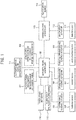
- FIG. 1 is a view illustrative of functions of a vehicle having a vehicle driving support device in the present embodiment.
- reference numeral 101 is an exterior travel environment detection device
- reference numeral 102 is a vehicle state detection device.
- the exterior travel environment detection device 101 includes for example, a camera, a laser radar, a GPS sensor, and the like, and is configured to recognize exterior situations of the travelling vehicle such as a distance from the travelling vehicle to a front vehicle, a vehicle travelling location, and the like.
- Information on the exterior situations that has been recognized by the exterior travel environment detection device 101 is input into an automatic travel controller 103.
- the vehicle state detection device 102 includes a G sensor or a vehicle speed sensor, for example, and is configured to detect current travelling state information of the vehicle. The information detected by the vehicle state detection device 102 is also input into the automatic travel controller 103.
- the automatic travel controller 103 is configured with a microcomputer including a CPU, a memory, and the like, for example.
- the automatic travel controller 103 is configured to determine interior and exterior situations of the vehicle based on the information received from the exterior travel environment detection device 101 and the vehicle state detection device 102, and then to carry out automatic travel control of controlling the steering angle or the vehicle speed so that the vehicle travels automatically depending on a determination result.
- the automatic travel controller 103 is configured to acquire a situation of a travel lane, the vehicle location, the vehicle speed, and the like together with information on a route or a traffic condition to a destination place, a route condition such as a traffic regulation, or travel environments including other vehicles, a presence or absence of an obstacle, and the like, from the exterior travel environment detection device 101 and the vehicle state detection device 102. Then, the automatic travel controller 103 is configured to calculate a traveling path based on the above pieces of information, and to set the steering angle or the vehicle speed to travel on the traveling path.
- the automatic travel controller 103 When there is a front vehicle ahead the vehicle, the automatic travel controller 103 is configured to carry out the automatic travel control for keeping a distance to the front vehicle constant depending on the vehicle speed, within a range that does not exceed a predefined speed set by the driver at a travel speed set device 110. On the other hand, when there is no front vehicle, the automatic travel controller 103 is configured to carry out the automatic travel control for keeping the speed set at the travel speed set device 110.
- the automatic travel controller 103 is configured to output a brake control instruction for the automatic travel control to a brake fluid pressure control actuator 104 or an accelerator control instruction for the automatic travel control to a throttle opening degree control actuator 105. Further, the automatic travel controller 103 is configured to output a turning control instruction for the automatic travel control to a turning angle control actuator 106.
- the brake fluid pressure control actuator 104 controls a brake system 107, whereas the throttle opening degree control actuator 105 controls an accelerator device 108. Furthermore, the steering angle control actuator 106 controls a turning device 109.
- the vehicle is made to travel autonomously without a driver's driving operation.
- an automatic/manual travelling changeover switch 111 is a switch that can be operated by a driver, and the automatic driving mode in which the automatic travel control is carried out and the manual driving mode in which the driver manually drives the vehicle are appropriately switchable.
- the above automatic travel control is in a condition where the driver operates the automatic/manual travelling changeover switch 111 to indicate the automatic driving mode, and is carried out only when the automatic travel controller 103 determines that the automatic travel control is possible from various pieces of information.
- the situation in which the automatic travel control is impossible includes a change of the destination place or the traveling path by the driver's circumstances, a sudden interruption of another vehicle, a sudden change of the weather, or the like.
- the automatic travel control is carried out on a highway, and the manual driving by the driver is carried out on a public road.
- the automatic travel controller 103 is configured to alarm the driver and passengers from a notification device 112 such as a buzzer or an alarm device, in an emergency or when a notification is necessary.
- a notification device 112 such as a buzzer or an alarm device
- the controlled state by the automatic travel controller 103 is input into a driving posture controller 113 from the automatic travel controller 103.
- the driving posture controller 113 is configured with, for example, a microcomputer including a CPU, a memory, and the like.
- the driving posture controller 113 and the automatic travel controller 103 can be commonly realized on an identical computer.
- the driving posture controller 113 receives inputs of a reclining angle of a seat back of a particular seat detected by a seat position sensor 114, and a slide amount in a front-rear direction of a seat bottom face of the particular seat.
- the particular seat corresponds to a driver's seat in the manual driving mode (hereinafter, simply referred to as driver's seat).
- the driving posture controller 113 controls positions of various parts of the driver's seat to carry out driving posture control of controlling a driver's driving posture to a posture depending on the driving mode (hereinafter, referred to as recommended driving posture).
- the driving posture controller 113 is configured to output a control instruction for adjusting the reclining angle of the seat back of the driver's seat and the slide amount of the seat bottom face of the driver's seat in the front-rear direction of the vehicle to a seat position actuator 115.
- the seat position actuator 115 is configured to control each part of a driver's seat 116.
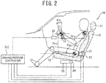
- FIG. 2 is a side view illustrative of the driver's seat of the vehicle.
- a driver' s seat 10 includes a headrest 11, a seat back 12, and a seat bottom 13, which are included in the driver's seat 116 of FIG. 1 .
- the seat back 12 is capable of tilting by a reclining motor 21, and a reclining sensor 22 is configured to detect a tilt angle of the seat back 12.
- the seat bottom 13 is slidable in the front-rear direction of the vehicle by the slide motor 23, and the slide sensor 24 detects a slide amount of the seat bottom 13.
- the seat position actuator 115 of FIG. 1 is configured with the reclining motor 21 and the slide motor 23.
- the seat position sensor 114 of FIG. 1 is configured with the reclining sensor 22 and the slide sensor 24.
- the steering actuator 25 is capable of adjusting the tilt angle of the steering wheel and a telescopic position, respectively.
- the driving posture controller 113 is configured to adjust a hip angle ⁇ HP , which is an angle made by axes of a driver's femoral region and body, by driving and controlling the reclining motor 21.
- the driving posture controller 113 is configured to adjust steering positions (a steering front-rear position PH ST , a steering top-bottom position Pv ST , and a steering angle ⁇ ST ) by driving and controlling the slide motor 23 and the steering actuator 25.
- the driving posture controller 113 is configured to set a condition where the seat back 12 rises so that driver's hands can reach the steering wheel, in the manual driving mode in which the automatic travel control with the automatic travel controller 103 is not being carried out, as illustrated in FIG. 3A .
- the driver should take the posture for driving the vehicle.
- the posture illustrated in FIG. 3A is assumed to be a driving posture (recommended manual driving posture) appropriate for the manual driving mode.
- the driving posture controller 113 is configured to make the seat back 14 closer to be horizontal, in the automatic driving mode in which the automatic travel control with the automatic travel controller 103 is being carried out, as illustrated in FIG. 3B .
- the driver should take the posture for entrusting the driving of the vehicle to the automatic travel control (the automatic travel controller 103).
- Such a posture illustrated in FIG. 3B is assumed to be a driving posture (recommended automatic driving posture) appropriate for the automatic driving mode.
- FIG. 4 is a flow chart illustrative of a driving posture control process procedure to be carried out by the driving posture controller 113.
- the driving posture control process starts its operation and is carried out repeatedly at every predefined sampling time.
- step S1 the driving posture controller 113 determines whether or not the recommended driving posture appropriate for each driving mode has been set. Then, when the recommended driving posture is not set, processing goes to step S2, whereas when the recommended driving posture has been set, processing goes to step S8 to be described below.
- step S2 the driving posture controller 113 acquires various types of data necessary for setting the recommended driving posture, and processing goes to step S3.
- the recommended driving posture is set depending on a driver's body size or a driver's personal physical feature (hereinafter, simply referred to as physical feature).
- the physical feature information representing a physical flexibility of the driver's body is used.
- step S2 for example, the slide amount of the seat and an opening degree of the door of the driver's seat, a driver's leg position, and the like, when the driver gets in the vehicle, are acquired.
- step S3 the driving posture controller 113 estimates the driver's body size.
- a driver's leg length is estimated by using a physical size model that has been stored beforehand, based on the slide amount of the seat when the driver gets in the vehicle.
- a driver's arm length from shoulder to hand and the driver's height are estimated from the estimated driver's leg length, by using the physical size model.
- step S4 the driving posture controller 113 estimates the driver's flexibility.
- the flexibility represents the softness of the driver's body. When the flexibility is low, the driver tends to be bad at twisting of the upper part of the body, the raising movement of the shoulder, and the like.
- the flexibility is estimated based on, for example, the driver's height estimated in step S3, the opening degree of the door of the driver's seat, and the driver's leg position when the driver gets in the vehicle.
- the driver's flexibility is categorized into three standards "low”, “medium”, and "high”.
- step S5 the driving posture controller 113 sets the manual driving posture that is the driving posture in the manual driving mode.
- the manual driving posture is, as illustrated in FIG. 5 , a driving posture of applying a certain steering press force T 1 to a steering wheel from the driver's hands.
- FIG. 6A and FIG. 6B are views illustrative of differences in the steering press force between a skilled driver and an unskilled driver.
- FIG. 6A illustrates the steering operation of the skilled driver
- FIG. 6B illustrates the steering operation of the unskilled driver.
- the steering press force is comparatively large (press force T 1 ), and a steering curved line is smooth like a sine wave, and it is understood that the steering operation is stable.
- the steering press force is comparatively small (press force T 2 ⁇ T 1 ), and the steering operation is unstable with many steering adjustments.
- the manual driving posture is set as the driving posture in which the average steering press force T 1 of the skilled driver is added to the steering wheel from the driver's hands.
- the settings of the driving posture are accomplished by setting posture conditions of the hip angle ⁇ HP , the steering front-rear position Ph ST , the steering top-bottom position Pv ST , and the steering angle ⁇ ST .
- posture conditions ( ⁇ HP , PH ST , Pv ST , and ⁇ ST ) for setting the manual driving posture are stored beforehand for every body size. Then, based on the driver's body size estimated in step S3, the posture conditions for setting the manual driving posture appropriate for the driver's body size are acquired. It is to be noted that to simplify the setting process, the body size may be categorized into three standards of "low”, “medium” , and "high” to set the posture conditions.
- step S6 the driving posture controller 113 corrects the manual driving posture set in step S5 with the driver's flexibility estimated in step S4.
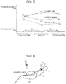
- FIG. 7 illustrates a relationship between the flexibilities and the operation accuracy
- the flexibility is low and the driver's driving posture is positioned closer to the steering wheel than the physical standard position
- the operation accuracy is higher.
- the operation accuracy is almost same with that in the physical standard position.
- the operation accuracy is high in both cases where the driver's driving posture is positioned at the physical standard position and where the driver's driving posture is positioned farther away from the steering wheel than the physical standard position.
- the operation accuracy is lower in the case where the driver's driving posture is closer to the steering than the physical standard position.
- the operation accuracy in this case is almost same with that of the case where the flexibility is low and the driver's driving posture is closer to the steering wheel than the physical standard position.
- the operation accuracy is different depending on the feature of each individual.
- the manual driving posture is corrected to improve the operation accuracy more.
- the manual driving posture set in step S5 is set to the recommended driving posture in the manual driving mode without a change.
- the steering front-rear position Ph ST of the manual driving posture set in step S5 is corrected to be closer to the steering wheel, and is set to the recommended driving posture in the manual driving mode.
- the correction amount of the steering front-rear position Ph ST is set to equal to or shorter than 40 mm, in which the driver can operate the steering wheel without degrading the operation accuracy.
- step S7 the driving posture controller 113 sets the recommended driving posture in the automatic driving mode.
- the automatic driving posture is set to the driving posture such that the hip angle ⁇ HP is an obtuse angle, as illustrated in FIG. 8 .
- the automatic driving posture is set by placing an importance on a comfortable posture (small physical burden).
- the comfortable posture has a high correlation with the hip angle ⁇ HP .
- the pressure amount of the driver's belly is smaller, as the hip angle ⁇ HP is larger.
- the muscle load and blood stream will be adversely affected and the load will be applied to the body. Therefore, there is a limit in the size of the hip angle ⁇ HP that allows the driver to take a comfortable posture.
- the posture in which the hip angle ⁇ HP is slightly smaller than 180 degrees is the posture in which the driver's physical burden amount is the minimum. Then, this posture is set as the automatic driving posture.
- step S8 the driving posture controller 113 determines whether or not the automatic travel control is being carried out at the automatic travel controller 103. In other words, the driving posture controller 113 determines whether or not the driving mode is the automatic driving mode. Then, in the automatic driving mode, processing goes to step S9, and in the manual driving mode, processing goes to step S11 to be described below.
- step S9 the driving posture controller 113 determines whether or not it is the timing when the automatic driving mode should be shifted to the manual driving mode. For example, when the vehicle enters a public road from a highway, or when it is determined that the automatic travel control cannot be continued by a sudden change in the travel environment or the like, the driving posture controller 113 determines that it is the timing when the automatic driving mode should be shifted to the manual driving mode. Then, when the automatic driving mode continues, just stand by without a change, or when the driving posture controller 113 determines that the driving mode should be shifted to the manual driving mode, processing goes to step S10.
- step S10 the driving posture controller 113 drives and controls a reclining motor 21, a slide motor 23, and a steering actuator 25, while determining the driving posture based on detection signals of the reclining sensor 22 and the slide sensor 24. In this manner, the driving posture is switched to the recommended manual driving posture set in step S6.
- step S11 the driving posture controller 113 determines whether or not it is the timing when the manual driving mode should be shifted to the automatic driving mode. For example, when the driver operates the automatic/manual travelling changeover switch 111 to make a state indicative of the automatic driving mode, the driving posture controller 113 determines that it is the timing when the manual driving mode should be shifted to the automatic driving mode. Then, when the manual driving mode continues, just stand by without a change, and when the driving posture controller 113 determines that the driving mode should be shifted to the automatic driving mode, processing goes to step S12.
- step S12 the driving posture controller 113 drives and controls the reclining motor 21, the slide motor 23, and the steering actuator 25, while determining the driving posture based on detection signals of the reclining sensor 22 and the slide sensor 24. In this manner, the driving posture is switched to the recommended automatic driving posture set in step S7.
- the driving posture controller 113 estimates the driver's body size such as a leg length, an arm length from shoulder to hand, or the like from the seat slide amount of the driver's seat when the driver gets in the vehicle (step S3 of FIG. 4 ).
- the driver's physical feature is estimated from the door opening degree when the driver gets in the vehicle (step S4). Then, the recommended driving posture appropriate for the manual driving mode and the recommended driving posture appropriate for the automatic driving mode are set based on the body size and the physical feature that have been estimated.
- the driver tends to open a vehicle door comparatively largely to get in the vehicle.
- the slide amount of the driver's seat when the driver gets in the vehicle is comparatively large.
- the driver's body size and physical feature are estimated by using such a difference in action when the driver gets in the vehicle depending on the body size and the physical feature.
- the posture in which a steering press force is equal to or larger than a certain amount is set as a driving posture in the manual driving mode (step S5), and is then corrected with the physical feature by which the driving posture has been estimated (step S6).
- the driving posture controller 113 determines that the automatic driving mode should be shifted to the manual driving mode (step S9: Yes) . Then, the driving posture controller 113 controls each part of driver's seat, and switches the driver's posture to the recommended manual driving posture that has been set based on the driver's body size and physical feature (step S10).
- the driver's posture is changed to the posture familiar with the body as usual as a manual driving posture. Therefore, the driver is able to recognize easily that it is necessary to switch to the manual driving mode. Thus, the driver operates the automatic/manual traveling changeover switch 111 so that shifting to the manual driving can be accomplished naturally.
- the recommended manual driving posture is set to the posture with the steering press force being equal to or larger than a certain amount in consideration of the driver's body size and physical feature. Therefore, in the manual driving mode, from the time point when the driver holds the steering wheel, the stable steering operation can be realized.
- the automatic travel controller 103 When the driver operates the automatic/manual traveling changeover switch 111 in driving the vehicle in the manual driving mode, the automatic travel controller 103 starts the automatic travel control. Then, the driving posture controller 113 determines that the manual driving mode should be shifted to the automatic driving mode (step S11: Yes). Then, the driving posture controller 113 controls each part of the driver's seat, and switches the driver's posture to the recommended automatic driving posture (step S12).
- steps S10 and S12 processing is carried out to make the reclining angle of the driver's seat in the automatic driving mode larger than the reclining angle of the driver's seat in the manual driving mode.
- the driver's posture is the posture with a comparatively large hip angle.
- the driver in the automatic driving mode, the driver is able to take a comfortable posture, and driver's fatigue in the travelling process is reduced.
- the driver by being replaced with such a comfortable posture in this manner, the driver can understand the situation easily that the driver may entrust the driving to the vehicle in the automatic travel control.
- the recommended automatic driving posture is set in consideration of the belly pressure amount and the muscle burden of the body maintenance.
- the belly pressure amount is smaller, as the hip angle is larger, and the muscle burden of the body maintenance is gradually increased in a region where the hip angle is larger than a given value.
- the recommended automatic driving posture is set in consideration of this, it is possible for the driver to take the posture where the driver's physical burden is the minimum in the automatic driving mode. Thus, the driver's fatigue in the travelling process in the automatic driving mode can be reduced effectively.
- the driver's posture is changed to the recommended driving posture in accordance with each driving mode that has been set in consideration of the driver's body size and physical feature.
- the posture in the manual driving mode, the posture is controlled to be the driving posture (high steering stability/high operation accuracy) that is good in the steering operability.
- the posture in the automatic driving mode, the posture is controlled so that the driver's fatigue is small in the travelling process.
- the driver is able to recognize the switching of the driving mode easily, as compared to a case where the switching of the driving mode is alarmed by a beep, sound, or seat vibration.
- the driving posture in each driving mode is set based on the driver's body size and physical feature, the driving posture appropriate for each driving mode can be set.
- the reclining motor 21 corresponds to a reclining angle adjustment unit
- the slide motor 23 corresponds to a front-rear position adjustment unit
- the steering actuator 25 corresponds to a steering adjustment unit.
- step S3 corresponds to a body size estimation unit
- step S4 corresponds to a physical feature estimation unit
- step S5 corresponds to a manual driving posture setting unit
- step S6 corresponds to a manual driving posture correction unit
- step S10 and S12 correspond to a reclining angle controller.
Landscapes
- Engineering & Computer Science (AREA)
- Transportation (AREA)
- Mechanical Engineering (AREA)
- Aviation & Aerospace Engineering (AREA)
- Automation & Control Theory (AREA)
- Chemical & Material Sciences (AREA)
- Combustion & Propulsion (AREA)
- Human Computer Interaction (AREA)
- Steering Control In Accordance With Driving Conditions (AREA)
- Control Of Driving Devices And Active Controlling Of Vehicle (AREA)
- Seats For Vehicles (AREA)
- Steering Controls (AREA)
Abstract

Description
- The present invention relates to a vehicle driving support device and a vehicle driving support method, in which an automatic driving mode and a manual driving mode are switchable.
- Conventionally, for example, one technology of controlling a vehicle speed or a steering angle based on information from various sensors for autonomous travel includes the technology described in patent literature 1. In this technology, when an automatic driving mode in which a vehicle travels autonomously and a manual driving mode in which the driver manually drives the vehicle are switched, the switching of the driving mode is alarmed to the driver by an alarm display, sound, sheet vibration, or the like.
- PLT 1:
JP H09-161196 A - In the technology as described in patent literature 1, however, the switching of the driving mode is alarmed to the driver by the alarm display, sound, sheet vibration, or the like. Hence, it is difficult for the driver to understand what the alarm intends to notify.
- Thus, the present invention has an object to provide a vehicle driving support device and vehicle driving support method, by which it is easy for the driver to understand the switching of the driving mode.
- In order to solve the above problem, according to one aspect of the present invention, it is configured to be switchable between an automatic driving mode of carrying out automatic travel control of automatically operating a turning mechanism independent of a steering operation of a driver and a manual driving mode of operating the turning mechanism depending on the steering operation of the driver.
- Then, a reclining angle of the driver's seat in the automatic driving mode is set to be larger than the reclining angle of the driver's seat in the manual driving mode.
- According to another aspect of the present invention, the reclining angle of the driver's seat is changed depending on whether the driving mode is the automatic driving mode or the manual driving mode. In this situation, since the reclining angle of the driver's seat in the automatic driving mode is larger than the reclining angle of the driver's seat in the manual driving mode, it is possible for the driver to understand the switching of the driving mode with ease.
-
-
FIG. 1 is a view illustrative of functions of a vehicle having a vehicle driving support device in one embodiment of the present invention; -
FIG. 2 is a side view illustrative of a driver's seat of the vehicle; -
FIG. 3A and FIG. 3B are views illustrative of driving postures in an automatic driving mode and a manual driving mode; -
FIG. 4 is a flow chart illustrative of a driving posture control process procedure; -
FIG. 5 is a view illustrative of a recommended manual driving posture; -
FIG. 6A and FIG. 6B are views illustrative of relationships between a steering stability and a steering press force; -
FIG. 7 is a view illustrative of relationships between physical features and operation accuracy; -
FIG. 8 is a view illustrative of a recommended automatic driving posture; -
FIG. 9 is a view illustrative of a relationship between a hip angle and a comfortable posture; -
FIG. 10 is a view illustrative of another example of the vehicle driving support device; -
FIG. 11 is a view illustrative of yet another example of the vehicle driving support device; and -
FIG. 12 is a view illustrative of further another example of the vehicle driving support device. - Hereinafter, embodiments of the present invention will be described with reference to the attached drawings.
-
FIG. 1 is a view illustrative of functions of a vehicle having a vehicle driving support device in the present embodiment. - In the drawing,
reference numeral 101 is an exterior travel environment detection device, andreference numeral 102 is a vehicle state detection device. The exterior travelenvironment detection device 101 includes for example, a camera, a laser radar, a GPS sensor, and the like, and is configured to recognize exterior situations of the travelling vehicle such as a distance from the travelling vehicle to a front vehicle, a vehicle travelling location, and the like. Information on the exterior situations that has been recognized by the exterior travelenvironment detection device 101 is input into anautomatic travel controller 103. - In addition, the vehicle
state detection device 102 includes a G sensor or a vehicle speed sensor, for example, and is configured to detect current travelling state information of the vehicle. The information detected by the vehiclestate detection device 102 is also input into theautomatic travel controller 103. - The
automatic travel controller 103 is configured with a microcomputer including a CPU, a memory, and the like, for example. - The
automatic travel controller 103 is configured to determine interior and exterior situations of the vehicle based on the information received from the exterior travelenvironment detection device 101 and the vehiclestate detection device 102, and then to carry out automatic travel control of controlling the steering angle or the vehicle speed so that the vehicle travels automatically depending on a determination result. - To be specific, the
automatic travel controller 103 is configured to acquire a situation of a travel lane, the vehicle location, the vehicle speed, and the like together with information on a route or a traffic condition to a destination place, a route condition such as a traffic regulation, or travel environments including other vehicles, a presence or absence of an obstacle, and the like, from the exterior travelenvironment detection device 101 and the vehiclestate detection device 102. Then, theautomatic travel controller 103 is configured to calculate a traveling path based on the above pieces of information, and to set the steering angle or the vehicle speed to travel on the traveling path. When there is a front vehicle ahead the vehicle, theautomatic travel controller 103 is configured to carry out the automatic travel control for keeping a distance to the front vehicle constant depending on the vehicle speed, within a range that does not exceed a predefined speed set by the driver at a travelspeed set device 110. On the other hand, when there is no front vehicle, theautomatic travel controller 103 is configured to carry out the automatic travel control for keeping the speed set at the travelspeed set device 110. - In addition, the
automatic travel controller 103 is configured to output a brake control instruction for the automatic travel control to a brake fluidpressure control actuator 104 or an accelerator control instruction for the automatic travel control to a throttle openingdegree control actuator 105. Further, theautomatic travel controller 103 is configured to output a turning control instruction for the automatic travel control to a turningangle control actuator 106. - The brake fluid
pressure control actuator 104 controls abrake system 107, whereas the throttle openingdegree control actuator 105 controls anaccelerator device 108. Furthermore, the steeringangle control actuator 106 controls aturning device 109. Thus, by operating an accelerator, a brake, or a steering wheel automatically, the vehicle is made to travel autonomously without a driver's driving operation. - In addition, an automatic/manual
travelling changeover switch 111 is a switch that can be operated by a driver, and the automatic driving mode in which the automatic travel control is carried out and the manual driving mode in which the driver manually drives the vehicle are appropriately switchable. - The above automatic travel control is in a condition where the driver operates the automatic/manual
travelling changeover switch 111 to indicate the automatic driving mode, and is carried out only when theautomatic travel controller 103 determines that the automatic travel control is possible from various pieces of information. Herein, the situation in which the automatic travel control is impossible includes a change of the destination place or the traveling path by the driver's circumstances, a sudden interruption of another vehicle, a sudden change of the weather, or the like. - In addition, in the present embodiment, for example, the automatic travel control is carried out on a highway, and the manual driving by the driver is carried out on a public road.
- Further, the
automatic travel controller 103 is configured to alarm the driver and passengers from anotification device 112 such as a buzzer or an alarm device, in an emergency or when a notification is necessary. - In addition, the controlled state by the
automatic travel controller 103 is input into adriving posture controller 113 from theautomatic travel controller 103. Thedriving posture controller 113 is configured with, for example, a microcomputer including a CPU, a memory, and the like. Thedriving posture controller 113 and theautomatic travel controller 103 can be commonly realized on an identical computer. - The
driving posture controller 113 receives inputs of a reclining angle of a seat back of a particular seat detected by aseat position sensor 114, and a slide amount in a front-rear direction of a seat bottom face of the particular seat. Herein, the particular seat corresponds to a driver's seat in the manual driving mode (hereinafter, simply referred to as driver's seat). - Then, upon detection of the switching between the automatic driving and the manual driving, the
driving posture controller 113 controls positions of various parts of the driver's seat to carry out driving posture control of controlling a driver's driving posture to a posture depending on the driving mode (hereinafter, referred to as recommended driving posture). To be specific, the drivingposture controller 113 is configured to output a control instruction for adjusting the reclining angle of the seat back of the driver's seat and the slide amount of the seat bottom face of the driver's seat in the front-rear direction of the vehicle to aseat position actuator 115. Theseat position actuator 115 is configured to control each part of a driver'sseat 116. -
FIG. 2 is a side view illustrative of the driver's seat of the vehicle. - As illustrated in this
FIG. 2 , a driver' sseat 10 includes aheadrest 11, a seat back 12, and a seat bottom 13, which are included in the driver'sseat 116 ofFIG. 1 . The seat back 12 is capable of tilting by areclining motor 21, and areclining sensor 22 is configured to detect a tilt angle of the seat back 12. In addition, the seat bottom 13 is slidable in the front-rear direction of the vehicle by theslide motor 23, and theslide sensor 24 detects a slide amount of theseat bottom 13. - Here, the seat position actuator 115 of
FIG. 1 is configured with thereclining motor 21 and theslide motor 23. In addition, theseat position sensor 114 ofFIG. 1 is configured with thereclining sensor 22 and theslide sensor 24. - Further, the steering
actuator 25 is capable of adjusting the tilt angle of the steering wheel and a telescopic position, respectively. - The driving
posture controller 113 is configured to adjust a hip angle θHP, which is an angle made by axes of a driver's femoral region and body, by driving and controlling thereclining motor 21. In addition, the drivingposture controller 113 is configured to adjust steering positions (a steering front-rear position PHST, a steering top-bottom position PvST, and a steering angle θST) by driving and controlling theslide motor 23 and thesteering actuator 25. - To be specific, the driving
posture controller 113 is configured to set a condition where the seat back 12 rises so that driver's hands can reach the steering wheel, in the manual driving mode in which the automatic travel control with theautomatic travel controller 103 is not being carried out, as illustrated inFIG. 3A . In other words, the driver should take the posture for driving the vehicle. The posture illustrated inFIG. 3A is assumed to be a driving posture (recommended manual driving posture) appropriate for the manual driving mode. - On the other hand, the driving
posture controller 113 is configured to make the seat back 14 closer to be horizontal, in the automatic driving mode in which the automatic travel control with theautomatic travel controller 103 is being carried out, as illustrated inFIG. 3B . In other words, the driver should take the posture for entrusting the driving of the vehicle to the automatic travel control (the automatic travel controller 103). Such a posture illustrated inFIG. 3B is assumed to be a driving posture (recommended automatic driving posture) appropriate for the automatic driving mode. -
FIG. 4 is a flow chart illustrative of a driving posture control process procedure to be carried out by the drivingposture controller 113. When the engine starts, the driving posture control process starts its operation and is carried out repeatedly at every predefined sampling time. - At first, in step S1, the driving
posture controller 113 determines whether or not the recommended driving posture appropriate for each driving mode has been set. Then, when the recommended driving posture is not set, processing goes to step S2, whereas when the recommended driving posture has been set, processing goes to step S8 to be described below. - In step S2, the driving
posture controller 113 acquires various types of data necessary for setting the recommended driving posture, and processing goes to step S3. In the present embodiment, the recommended driving posture is set depending on a driver's body size or a driver's personal physical feature (hereinafter, simply referred to as physical feature). In addition, as the physical feature, information representing a physical flexibility of the driver's body is used. Thus, in step S2, for example, the slide amount of the seat and an opening degree of the door of the driver's seat, a driver's leg position, and the like, when the driver gets in the vehicle, are acquired. - In step S3, the driving
posture controller 113 estimates the driver's body size. At first, a driver's leg length is estimated by using a physical size model that has been stored beforehand, based on the slide amount of the seat when the driver gets in the vehicle. Next, a driver's arm length from shoulder to hand and the driver's height are estimated from the estimated driver's leg length, by using the physical size model. - In step S4, the driving
posture controller 113 estimates the driver's flexibility. The flexibility represents the softness of the driver's body. When the flexibility is low, the driver tends to be bad at twisting of the upper part of the body, the raising movement of the shoulder, and the like. Herein, the flexibility is estimated based on, for example, the driver's height estimated in step S3, the opening degree of the door of the driver's seat, and the driver's leg position when the driver gets in the vehicle. In the present embodiment, the driver's flexibility is categorized into three standards "low", "medium", and "high". - In step S5, the driving
posture controller 113 sets the manual driving posture that is the driving posture in the manual driving mode. Here, the manual driving posture is, as illustrated inFIG. 5 , a driving posture of applying a certain steering press force T1 to a steering wheel from the driver's hands. -
FIG. 6A and FIG. 6B are views illustrative of differences in the steering press force between a skilled driver and an unskilled driver. Here,FIG. 6A illustrates the steering operation of the skilled driver, andFIG. 6B illustrates the steering operation of the unskilled driver. - As illustrated in
FIG. 6A , in a case of the skilled driver, the steering press force is comparatively large (press force T1), and a steering curved line is smooth like a sine wave, and it is understood that the steering operation is stable. On the other hand, as illustrated inFIG. 6B , in a case of the unskilled driver, the steering press force is comparatively small (press force T2 < T1), and the steering operation is unstable with many steering adjustments. - Thus, in the present embodiment, in order to realize the stable steering in the manual driving mode, the manual driving posture is set as the driving posture in which the average steering press force T1 of the skilled driver is added to the steering wheel from the driver's hands. The settings of the driving posture are accomplished by setting posture conditions of the hip angle θHP, the steering front-rear position PhST, the steering top-bottom position PvST, and the steering angle θST.
- These posture conditions (θHP, PHST, PvST, and θST) for setting the manual driving posture are stored beforehand for every body size. Then, based on the driver's body size estimated in step S3, the posture conditions for setting the manual driving posture appropriate for the driver's body size are acquired. It is to be noted that to simplify the setting process, the body size may be categorized into three standards of "low", "medium" , and "high" to set the posture conditions.
- In step S6, the driving
posture controller 113 corrects the manual driving posture set in step S5 with the driver's flexibility estimated in step S4. - As
FIG. 7 illustrates a relationship between the flexibilities and the operation accuracy, when the flexibility is low and the driver's driving posture is positioned closer to the steering wheel than the physical standard position, it is known that the operation accuracy is higher. In addition, in the position where the driver's driving posture is farther away from the steering wheel than the physical standard position, the operation accuracy is almost same with that in the physical standard position. - In contrast, when the flexibility is general or high, the operation accuracy is high in both cases where the driver's driving posture is positioned at the physical standard position and where the driver's driving posture is positioned farther away from the steering wheel than the physical standard position. In addition, in the case where the driver's driving posture is closer to the steering than the physical standard position, the operation accuracy is lower. However, the operation accuracy in this case is almost same with that of the case where the flexibility is low and the driver's driving posture is closer to the steering wheel than the physical standard position.
- Thus, the operation accuracy is different depending on the feature of each individual. Thus, in the present embodiment, in consideration of the flexibility that is a feature of an individual human body, the manual driving posture is corrected to improve the operation accuracy more.
- To be specific, in a case where the driver's flexibility is "medium" or "high" , the manual driving posture set in step S5 is set to the recommended driving posture in the manual driving mode without a change. On the other hand, in a case where the driver's flexibility is "low", the steering front-rear position PhST of the manual driving posture set in step S5 is corrected to be closer to the steering wheel, and is set to the recommended driving posture in the manual driving mode. Here, the correction amount of the steering front-rear position PhST is set to equal to or shorter than 40 mm, in which the driver can operate the steering wheel without degrading the operation accuracy.
- In step S7, the driving
posture controller 113 sets the recommended driving posture in the automatic driving mode. Here, the automatic driving posture is set to the driving posture such that the hip angle θHP is an obtuse angle, as illustrated inFIG. 8 . In the automatic driving mode, the driver does not have to take the driving posture. Therefore, the automatic driving posture is set by placing an importance on a comfortable posture (small physical burden). - As illustrated in
FIG. 9 , it is understood that the comfortable posture has a high correlation with the hip angle θHP. The pressure amount of the driver's belly is smaller, as the hip angle θHP is larger. However, if there is a part where a muscle load for maintaining the body is increased or the head position is lower than the horizontal line, the muscle load and blood stream will be adversely affected and the load will be applied to the body. Therefore, there is a limit in the size of the hip angle θHP that allows the driver to take a comfortable posture. - In the present embodiment, in consideration of the belly pressure amount and the muscle burden of the physical maintenance, it is determined that the posture in which the hip angle θHP is slightly smaller than 180 degrees is the posture in which the driver's physical burden amount is the minimum. Then, this posture is set as the automatic driving posture.
- In step S8, the driving
posture controller 113 determines whether or not the automatic travel control is being carried out at theautomatic travel controller 103. In other words, the drivingposture controller 113 determines whether or not the driving mode is the automatic driving mode. Then, in the automatic driving mode, processing goes to step S9, and in the manual driving mode, processing goes to step S11 to be described below. - In step S9, the driving
posture controller 113 determines whether or not it is the timing when the automatic driving mode should be shifted to the manual driving mode. For example, when the vehicle enters a public road from a highway, or when it is determined that the automatic travel control cannot be continued by a sudden change in the travel environment or the like, the drivingposture controller 113 determines that it is the timing when the automatic driving mode should be shifted to the manual driving mode. Then, when the automatic driving mode continues, just stand by without a change, or when the drivingposture controller 113 determines that the driving mode should be shifted to the manual driving mode, processing goes to step S10. - In step S10, the driving
posture controller 113 drives and controls areclining motor 21, aslide motor 23, and asteering actuator 25, while determining the driving posture based on detection signals of thereclining sensor 22 and theslide sensor 24. In this manner, the driving posture is switched to the recommended manual driving posture set in step S6. - In step S11, the driving
posture controller 113 determines whether or not it is the timing when the manual driving mode should be shifted to the automatic driving mode. For example, when the driver operates the automatic/manual travellingchangeover switch 111 to make a state indicative of the automatic driving mode, the drivingposture controller 113 determines that it is the timing when the manual driving mode should be shifted to the automatic driving mode. Then, when the manual driving mode continues, just stand by without a change, and when the drivingposture controller 113 determines that the driving mode should be shifted to the automatic driving mode, processing goes to step S12. - In step S12, the driving
posture controller 113 drives and controls thereclining motor 21, theslide motor 23, and thesteering actuator 25, while determining the driving posture based on detection signals of thereclining sensor 22 and theslide sensor 24. In this manner, the driving posture is switched to the recommended automatic driving posture set in step S7. - An operation of the present embodiment will be described below.
- When a driver sets the key at a starting position to start the engine, the driving
posture controller 113 estimates the driver's body size such as a leg length, an arm length from shoulder to hand, or the like from the seat slide amount of the driver's seat when the driver gets in the vehicle (step S3 ofFIG. 4 ). In addition, the driver's physical feature (flexibility) is estimated from the door opening degree when the driver gets in the vehicle (step S4). Then, the recommended driving posture appropriate for the manual driving mode and the recommended driving posture appropriate for the automatic driving mode are set based on the body size and the physical feature that have been estimated. - When the body size is comparatively large and the flexibility is low, the driver tends to open a vehicle door comparatively largely to get in the vehicle. In addition, the slide amount of the driver's seat when the driver gets in the vehicle is comparatively large. Thus, the driver's body size and physical feature are estimated by using such a difference in action when the driver gets in the vehicle depending on the body size and the physical feature.
- Then, in accordance with the estimated body size, the posture in which a steering press force is equal to or larger than a certain amount is set as a driving posture in the manual driving mode (step S5), and is then corrected with the physical feature by which the driving posture has been estimated (step S6).
- As illustrated in
FIG. 7 , when the flexibility is low, even with the same body size, as the driver is closer to the steering wheel, the steering operation accuracy is higher, as compared to a case of standard flexibility. Thus, when the driver's flexibility is low, the manual driving posture that has been set depending on the body size is corrected so that the steering front-rear position PhST is smaller, and is set as the recommended manual driving posture. - For example, in a case where the setting has been made such that the driver is driving the vehicle on a highway in the automatic driving mode and then enters an interchange by manually driving the vehicle, it is necessary to switch from the automatic driving mode to the manual driving mode just before entering the interchange. In other words, when the vehicle location reaches just before the interchange while travelling in the automatic driving mode, the driving
posture controller 113 determines that the automatic driving mode should be shifted to the manual driving mode (step S9: Yes) . Then, the drivingposture controller 113 controls each part of driver's seat, and switches the driver's posture to the recommended manual driving posture that has been set based on the driver's body size and physical feature (step S10). - Accordingly, the driver's posture is changed to the posture familiar with the body as usual as a manual driving posture. Therefore, the driver is able to recognize easily that it is necessary to switch to the manual driving mode. Thus, the driver operates the automatic/manual traveling
changeover switch 111 so that shifting to the manual driving can be accomplished naturally. - In addition, the recommended manual driving posture is set to the posture with the steering press force being equal to or larger than a certain amount in consideration of the driver's body size and physical feature. Therefore, in the manual driving mode, from the time point when the driver holds the steering wheel, the stable steering operation can be realized.
- When the driver operates the automatic/manual traveling
changeover switch 111 in driving the vehicle in the manual driving mode, theautomatic travel controller 103 starts the automatic travel control. Then, the drivingposture controller 113 determines that the manual driving mode should be shifted to the automatic driving mode (step S11: Yes). Then, the drivingposture controller 113 controls each part of the driver's seat, and switches the driver's posture to the recommended automatic driving posture (step S12). - In other words, in steps S10 and S12, processing is carried out to make the reclining angle of the driver's seat in the automatic driving mode larger than the reclining angle of the driver's seat in the manual driving mode.
- Accordingly, the driver's posture is the posture with a comparatively large hip angle. Thus, in the automatic driving mode, the driver is able to take a comfortable posture, and driver's fatigue in the travelling process is reduced. In addition, by being replaced with such a comfortable posture in this manner, the driver can understand the situation easily that the driver may entrust the driving to the vehicle in the automatic travel control.
- In this situation, the recommended automatic driving posture is set in consideration of the belly pressure amount and the muscle burden of the body maintenance. The belly pressure amount is smaller, as the hip angle is larger, and the muscle burden of the body maintenance is gradually increased in a region where the hip angle is larger than a given value. As the recommended automatic driving posture is set in consideration of this, it is possible for the driver to take the posture where the driver's physical burden is the minimum in the automatic driving mode. Thus, the driver's fatigue in the travelling process in the automatic driving mode can be reduced effectively.
- As described above, in the present embodiment, by changing a combination of the reclining angle of the driver's seat, the seat slide amount, and the steering position, respectively, the driver's posture is changed to the recommended driving posture in accordance with each driving mode that has been set in consideration of the driver's body size and physical feature. In this situation, in the manual driving mode, the posture is controlled to be the driving posture (high steering stability/high operation accuracy) that is good in the steering operability. In addition, in the automatic driving mode, the posture is controlled so that the driver's fatigue is small in the travelling process.
- Thus, on an occasion of switching the driving mode, as the position of each part in the driver's seat is controlled to change the driver's posture, the driver is able to recognize the switching of the driving mode easily, as compared to a case where the switching of the driving mode is alarmed by a beep, sound, or seat vibration. In addition, since the driving posture in each driving mode is set based on the driver's body size and physical feature, the driving posture appropriate for each driving mode can be set.
- It is to be noted that in
FIG. 2 , thereclining motor 21 corresponds to a reclining angle adjustment unit, theslide motor 23 corresponds to a front-rear position adjustment unit, and thesteering actuator 25 corresponds to a steering adjustment unit. - Further, in
FIG. 4 , step S3 corresponds to a body size estimation unit, and step S4 corresponds to a physical feature estimation unit. In addition, step S5 corresponds to a manual driving posture setting unit, and step S6 corresponds to a manual driving posture correction unit. In addition, step S10 and S12 correspond to a reclining angle controller. - In the present embodiment, the following effectiveness is obtainable.
- (1) When detecting the switching from the manual driving mode to the automatic driving mode, the driving
posture controller 113 increases the reclining angle of the driver's seat to the reclining angle in the automatic driving mode from the reclining angle in the manual driving mode. In addition, when detecting the switching from the automatic driving mode to the manual driving mode, the drivingposture controller 113 decreases the reclining angle of the driver's seat to the reclining angle in the manual driving mode from the reclining angle in the automatic driving mode.
Thus, the driver's posture is changed by changing the reclining angle of the driver's seat depending on the driving mode. In this situation, since the reclining angle of the driver's seat in the automatic driving mode is larger than the reclining angle of the driver's seat in the manual driving mode, the driver is able to understand the switching of the driving mode easily. - (2) The driving
posture controller 113 estimates the driver's body size. In addition, the drivingposture controller 113 sets the posture in which the driver's press amount against the steering wheel is equal to or larger than a certain value that enables the stable steering operation that is determined by the estimated driver's body size, as the recommended driving posture appropriate for the manual driving mode.
Thus, when the driving mode is switched to the manual driving mode, the steering press amount is equal to larger than a certain amount from the time when the driver holds the steering wheel. Therefore, the driver is able to carry out the stable steering operation. In addition, since the recommended driving posture in the manual driving mode is the posture familiar with the driver's body as usual as the posture in the manual driving, it is possible to shift to the manual driving mode from the automatic driving mode naturally. - (3) The driving
posture controller 113 estimates a driver's physical feature. Then, depending on the physical feature that has been estimated, the drivingposture controller 113 corrects the recommended driving posture in the manual driving mode that has been set based on the body size.
Thus, in consideration of the difference in the steering posture in which the driver easily operates the steering wheel depending on the individual human body feature, the recommended driving posture in the manual driving mode is determined depending on the driver's physical feature. Thus, in the manual driving mode, it is possible for the driver to take the driving posture more appropriate for the driver. - (4) The driving
posture controller 113 estimates the driver's physical flexibility as a driver's physical feature based on a driver's action at the time of getting in or out of the vehicle.
Even with the same body size, the driving posture that improves the steering operation accuracy is different depending on the difference in physical flexibility. For example, when the flexibility is standard or high, the steering accuracy is higher, as the steering wheel is closer to the driver than the physical standard position. On the other hand, when the flexibility is low, the operation accuracy is lower, as the steering wheel is closer to the driver than the physical standard position. In consideration of these facts, the recommended driving posture in the manual driving mode is determined, so that the driver can take the driving posture more appropriate for the driver and the stable steering operation can be achieved. - (5) The driving
posture controller 113 changes the slide amount of the seat bottom in addition to the reclining angle. Then, when the drivingposture controller 113 detects switching from the automatic driving mode to the manual driving mode, the drivingposture controller 113 sets the position of the driver's seat bottom face in the front-rear direction of the vehicle so that the driver's driving posture is the recommended driving posture in the manual driving mode.
Thus, as the reclining angle and the slide amount of the driver's seat are configured to be changeable, the driver's hip angle and the distance from the driver's seat to the steering wheel in the front-rear direction of the vehicle can be adjusted. Thus, the driver's posture can be changed to the recommended driving posture appropriate for the driving mode appropriately. - (6) The driving
posture controller 113 changes the steering position in addition to the reclining angle of the seat back. When the drivingposture controller 113 detects switching from the automatic driving mode to the manual driving mode, the drivingposture controller 113 sets the position of the steering wheel in the front-rear direction and in an up-down direction of the vehicle so that the driver' s driving posture is the recommended driving posture in the manual driving mode.
Thus, since the reclining angle and the slide amount of the driver's seat and the steering position are configured to be changeable, the positional relationship of the driver's hip angle, the driver's seat, and the steering wheel can be adjusted appropriately. Thus, the posture control is enabled to the recommended driving posture appropriate for the driving mode with accuracy. - (7) When the driving
posture controller 113 detects switching from the manual driving mode to the automatic driving mode, the reclining angle of the driver' s seat is made larger to the reclining angle in the automatic driving mode from the reclining angle in the manual driving mode. In addition, when the drivingposture controller 113 detects switching from the automatic driving mode to the manual driving mode, the reclining angle of the driver's seat is made smaller to the reclining angle in the manual driving mode from the reclining angle in the automatic driving mode.
Thus, the driver's posture is changed by changing the reclining angle of the driver's seat depending on the driving mode. As the driving posture is changed to be appropriate for the driving mode, it is possible for the driver to understand the switching of the driving mode easily. -
- (1) In the above embodiment, instead of the configuration of
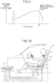
FIG. 2 , acontact pressure sensor 26 can be arranged in the seat back 12, as illustrated inFIG. 10 . In such a configuration, the steering press force can be measured indirectly from a relationship of the action and reaction of thecontact pressure sensor 26 of the seat back 12. Thus, it is possible to adjust the driving posture in the manual driving mode with certainty so that the steering press force is equal to or larger than a certain amount T1. - (2) In the above embodiment, instead of the configuration of
FIG. 2 , acontact pressure sensor 27 can be arranged in the seat bottom face, as illustrated inFIG. 11 . In such a configuration, when the driver is seated, it is possible to estimate the driver's weight. Thus, the estimation accuracy of the driver's physical size can be improved by using the driver's leg length that has been estimated based on the seat slide amount detected by theslide sensor 23 when the driver gets in the vehicle and the driver's weight that has been estimated based on a detection signal of thecontact pressure sensor 27. - (3) In the above embodiment, instead of the configuration of
FIG. 2 , thecontact pressure sensor 26 ofFIG. 10 and thecontact pressure sensor 27 ofFIG. 11 can be included, as illustrated inFIG. 12 . Accordingly, it is possible to estimate the driver's body size with accuracy and to enable the posture control with high accuracy in switching to the manual driving mode. -
- (1) In the above embodiment, the reliability degree of the automatic travel control by the
automatic travel controller 103 is detected, so that the driving posture in the automatic driving mode can be adjusted depending on the reliability degree. Here, the reliability degree of the automatic travel control is a system confidence degree representing the certainty of the automatic travel control. The reliability degree is lower, as there is a higher possibility of malfunction in the automatic travel control. Then, while the vehicle is travelling in the automatic driving mode, the drivingposture controller 113 makes the driver's driving posture closer to the recommended driving posture in the manual driving mode from the recommended driving posture in the automatic driving mode, as the reliability degree of the automatic travel control is lower.
In other words, the driving posture is configured to be adjustable in a stepwise manner between the recommended manual driving posture set in step S6 ofFIG. 4 and the recommended automatic driving posture set in step S7. Then, adjustments are enabled such that as the reliability degree of the automatic travel control is higher, the driving posture is closer to the recommended automatic driving posture, whereas the reliability degree of the automatic travel control is lower, the driving posture is closer to the recommended manual driving posture.
Thus, as the posture is controlled in accordance with the system confidence degree of the vehicle in the automatic travel control, it is possible to shift from an automatic driving state to a manual driving state in a stepwise manner.
In addition, the reliability degree of the automatic travel control described above is detected by any one or a combination of the number of the sensing objects in the automatic travel control, the number of sensors necessary for sensing in the automatic travel control, complexity of the sensing object in the automatic travel control such as a movement forecast of a bicycle, the number of selections in the travel path, an operation amount needed for control object determination, and energy needed for the automatic travel control.
Thus, it is possible to understand the system confidence degree in relation to the sensing or recognition in the automatic travel control, through the driving posture easily. - (2) In the above embodiment, the description has been given of the case where the automatic travel control is carried out such that even a driver does not operate an operation element, and the vehicle is controlled to travel autonomously. The present invention, however, is applicable to a case where a turning mechanism is controlled to autonomously operate without the driver's operation of the operation element at least.
- Heretofore, the entire disclosure of Japanese Patent Application No.
2013-152548 filed on July 23, 2013 - Herein, a limited number of embodiments have been described with reference to the drawings. The present invention, however, is not limited to them. It is apparent for a person skilled in the art that there are variations in the embodiment based upon the above disclosure.
- 10 ... driver's seat, 11 ... headrest, 12 ... seat back, 13 ... seat bottom, 21 ... reclining motor, 22 ... reclining sensor, 23 ... slide motor, 24 ... slide sensor, 25 ... steering actuator, 101 ... exterior travel environment detection device, 102 ... vehicle state detection device, 103 ... automatic travel controller, 104 ... brake fluid pressure control actuator, 105 ... throttle opening degree control actuator, 106 ... turning angle control actuator, 107 ... brake device, 108 ... accelerator device, 109 ... turning device, 110 ... travel speed set device, 111 ... automatic/manual traveling changeover switch, 112 ... alarm device, 113 ... driving posture controller, 114 ... seat position sensor, 115 ... seat position actuator, 116 ... driver's seat
Claims (8)
- A vehicle driving support device, comprising:a reclining angle adjustment unit capable of adjusting a reclining angle of a driver's seat; anda reclining angle controller configured to change the reclining angle by controlling the reclining angle adjustment unit depending on a driving mode, the driving mode being switchable between an automatic driving mode of carrying out automatic travel control for automatically operating a steering mechanism independent of a steering operation of a driver and a manual driving mode of operating the steering mechanism depending on the steering operation of the driver,wherein the reclining angle controller is configured to control the reclining angle adjustment unit so that the reclining angle in the automatic driving mode is larger than the reclining angle in the manual driving mode.
- The vehicle driving support device according to claim 1, further comprising:a body size estimation unit configured to estimate a driver's body size; anda manual driving posture setting unit configured to set a posture in which a driver's pressing force against a steering wheel is equal to or larger than a certain value that enables stable steering that is determined by the driver's body size estimated by the body size estimation unit, as a driving posture in accordance with the manual driving mode,wherein the reclining angle controller is configured to control the reclining angle adjustment unit so that the driving posture of the driver in the manual driving mode is the posture set by the manual driving posture setting unit.
- The vehicle driving support device according to claim 2, further comprising:a physical feature estimation unit configured to estimate a personal physical feature of the driver; anda manual driving posture correction unit configured to correct the driving posture in accordance with the manual driving mode set by the manual driving posture setting unit with the personal physical feature estimated by the physical feature estimation unit.
- The vehicle driving support device according to claim 3, wherein the physical feature estimation unit is configured to estimate a physical flexibility of the driver as the personal physical feature of the driver, based on an action of the driver when the driver gets in or out of a vehicle.
- The vehicle driving support device according to any one of claim 2 to claim 4, further comprising a front-rear position adjustment unit capable of adjusting a seat bottom face of the particular seat in a front-rear direction of the vehicle,
wherein the reclining angle controller is configured to control the front-rear position adjustment unit in addition to the reclining angle adjustment unit, and
wherein the reclining angle controller, when detecting switching from the automatic driving mode to the manual driving mode, is configured to control the front-rear position adjustment unit so that a position of the seat bottom face of the particular seat in the front-rear direction of the vehicle becomes a position in which the driving posture of the driver becomes the posture set by the manual driving posture setting unit. - The vehicle driving support device according to any one of claim 2 to claim 5, further comprising a steering adjustment unit capable of adjusting a position of a steering wheel in the front-rear direction and a top-bottom direction of the vehicle,
wherein the reclining angle controller is configured to control the steering adjustment unit in addition to the reclining angle adjustment unit, and
wherein the reclining angle controller, when detecting switching from the manual driving mode to the automatic driving mode, is configured to control the steering adjustment unit so that the position of the steering wheel in the front-rear direction and the top-bottom direction of the vehicle becomes the position in which the driving posture of the driver is the posture set by the manual driving posture setting unit. - The vehicle driving support device according to any one of claim 1 to claim 6,
wherein the automatic travel control is to make the vehicle travel automatically independent of the steering operation of the driver with a steering element,
further comprising a reliability degree detection unit configured to detect a reliability degree of the automatic travel control, based upon at least one of the number of sensing objects in the automatic travel control, the number of sensors necessary for sensing in the automatic travel control, a complexity of a sensing object in the automatic travel control, and an operation amount in the automatic travel control,
wherein the reclining angle controller is configured to control the reclining angle adjustment unit so that as the reliability degree detected by the reliability degree detection unit is lower in the automatic travel control, the driving posture of the driver is closer to the driving posture in accordance with the automatic driving mode from the driving posture in accordance with the manual driving mode. - A vehicle driving support method, comprising:switching between an automatic driving mode of carrying out automatic travel control of automatically operating a steering mechanism independent of a steering operation of a driver and a manual driving mode of operating the steering mechanism depending on the steering operation of the driver; andcontrolling so that a reclining angle of the driver's seat in the automatic driving mode is larger than the reclining angle of the driver' s seat in a manual driving mode.
Applications Claiming Priority (2)
| Application Number | Priority Date | Filing Date | Title |
|---|---|---|---|
| JP2013152548 | 2013-07-23 | ||
| PCT/JP2014/002793 WO2015011866A1 (en) | 2013-07-23 | 2014-05-27 | Vehicular drive assist device, and vehicular drive assist method |
Publications (3)
| Publication Number | Publication Date |
|---|---|
| EP3025921A1 true EP3025921A1 (en) | 2016-06-01 |
| EP3025921A4 EP3025921A4 (en) | 2016-08-03 |
| EP3025921B1 EP3025921B1 (en) | 2017-08-09 |
Family
ID=52392934
Family Applications (1)
| Application Number | Title | Priority Date | Filing Date |
|---|---|---|---|
| EP14828778.2A Active EP3025921B1 (en) | 2013-07-23 | 2014-05-27 | Vehicular drive assist device, and vehicular drive assist method |
Country Status (8)
| Country | Link |
|---|---|
| US (1) | US9738179B2 (en) |
| EP (1) | EP3025921B1 (en) |
| JP (1) | JP5967309B2 (en) |
| CN (1) | CN105579321B (en) |
| BR (1) | BR112016001620B1 (en) |
| MX (1) | MX345580B (en) |
| RU (1) | RU2626433C1 (en) |
| WO (1) | WO2015011866A1 (en) |
Cited By (14)
| Publication number | Priority date | Publication date | Assignee | Title |
|---|---|---|---|---|
| DE102016215805A1 (en) | 2016-08-23 | 2018-03-01 | Robert Bosch Gmbh | A method and controller for adjusting a seating position of an occupant of a vehicle to an operating mode of the vehicle |
| IT201700038081A1 (en) * | 2017-04-06 | 2018-10-06 | Italdesign Giugiaro Spa | Seat system for vehicles, in particular for autonomous driving vehicles. |
| US10150386B2 (en) | 2017-02-27 | 2018-12-11 | Nissan North America, Inc. | Autonomous vehicle seat positioning system |
| FR3072909A1 (en) * | 2017-10-31 | 2019-05-03 | Renault S.A.S | SYSTEM AND METHOD FOR ADJUSTING A DRIVER'S SEAT OF A MOTOR VEHICLE |
| FR3074466A1 (en) * | 2017-12-06 | 2019-06-07 | Psa Automobiles Sa | METHOD FOR CONTROLLING POSITIONS DURING DEPLOYMENT OF THE WHEEL OF AN AUTONOMOUS DRIVING VEHICLE |
| US10343555B2 (en) | 2017-02-27 | 2019-07-09 | Nissan North America, Inc. | Autonomous vehicle seat positioning system |
| EP3521107A4 (en) * | 2016-09-29 | 2019-08-28 | Nissan Motor Co., Ltd. | SWITCH POSITION SETTING METHOD, AND VEHICLE MANEUVER DEVICE |
| FR3079787A1 (en) * | 2018-04-09 | 2019-10-11 | Faurecia Sieges D'automobile | ADJUSTING THE POSITION OF A SEAT FOR A MOTOR VEHICLE |
| RU2703389C2 (en) * | 2017-02-07 | 2019-10-16 | ФОРД ГЛОУБАЛ ТЕКНОЛОДЖИЗ, ЭлЭлСи | Computer (embodiments) and method of controlling taxiing of vehicle |
| EP3587172A1 (en) * | 2018-06-22 | 2020-01-01 | Motherson Innovations Company Limited | Self-adjusting centre console with arm detection |
| EP3730334A1 (en) * | 2019-04-25 | 2020-10-28 | Transdev Group | Device for controlling for a motor vehicle, associated motor vehicle, control method and computer program |
| FR3105962A1 (en) * | 2020-01-03 | 2021-07-09 | Faurecia Interieur Industrie | Method for checking elements of a vehicle interior and associated devices |
| DE102020103200A1 (en) | 2020-02-07 | 2021-08-12 | Bayerische Motoren Werke Aktiengesellschaft | System and method for a vehicle with a driver assistance system for automated driving |
| EP4005864A1 (en) * | 2020-11-27 | 2022-06-01 | Hyundai Motor Company | Device and method for controlling travel of vehicle |
Families Citing this family (113)
| Publication number | Priority date | Publication date | Assignee | Title |
|---|---|---|---|---|
| US10647235B2 (en) * | 2014-06-09 | 2020-05-12 | Lear Corporation | Adjustable seat assembly with driving modes |
| JP6354424B2 (en) * | 2014-07-29 | 2018-07-11 | 日産自動車株式会社 | Vehicle control device |
| EP3000651B1 (en) | 2014-09-24 | 2018-02-21 | Volvo Car Corporation | A system and method for seat retraction during an autonomous driving mode |
| JP6269542B2 (en) * | 2015-03-12 | 2018-01-31 | トヨタ自動車株式会社 | Vehicle sun visor |
| JP6582458B2 (en) * | 2015-03-13 | 2019-10-02 | トヨタ自動車株式会社 | Driving position control device |
| JP6497182B2 (en) * | 2015-04-03 | 2019-04-10 | 日産自動車株式会社 | Driving posture adjustment device for autonomous driving vehicle |
| JP6503848B2 (en) * | 2015-04-03 | 2019-04-24 | 日産自動車株式会社 | Driving attitude adjustment device for an autonomous driving vehicle |
| JP6547399B2 (en) * | 2015-05-12 | 2019-07-24 | 日産自動車株式会社 | Vehicle seat |
| FR3038281B1 (en) * | 2015-07-03 | 2017-07-21 | Peugeot Citroen Automobiles Sa | METHOD FOR ASSISTING A DRIVER PROVIDING A DRIVING POSITION ACCORDING TO A CONTEXT OF DRIVING |
| JP6601028B2 (en) * | 2015-07-13 | 2019-11-06 | 日産自動車株式会社 | Vehicle operation control device and vehicle operation control method |
| FR3039123B1 (en) * | 2015-07-20 | 2017-07-21 | Peugeot Citroen Automobiles Sa | METHOD FOR AIDING THE ACTIVATION OF DRIVING ASSISTANCE MODES BY RECONFIGURING THE CUSTODY |
| JP6237725B2 (en) | 2015-07-27 | 2017-11-29 | トヨタ自動車株式会社 | Crew information acquisition device and vehicle control system |
| JP6304162B2 (en) * | 2015-07-27 | 2018-04-04 | トヨタ自動車株式会社 | Vehicle seat control device |
| DE102015012833A1 (en) * | 2015-10-02 | 2017-04-06 | Daimler Ag | Method for operating a motor vehicle and motor vehicles |
| EP3153346B1 (en) * | 2015-10-07 | 2019-09-25 | Volvo Car Corporation | A seat system for autonomous vehicles |
| US10116873B1 (en) * | 2015-11-09 | 2018-10-30 | Ambarella, Inc. | System and method to adjust the field of view displayed on an electronic mirror using real-time, physical cues from the driver in a vehicle |
| JP6185543B2 (en) | 2015-11-24 | 2017-08-23 | 株式会社Subaru | Armrest control device and armrest device |
| US9994125B2 (en) | 2016-01-12 | 2018-06-12 | Ford Global Technologies, Llc | System and method for vehicle seat monitoring |
| JP6620564B2 (en) * | 2016-01-15 | 2019-12-18 | 株式会社デンソー | Transfer control device |
| DE102016200513A1 (en) * | 2016-01-18 | 2017-07-20 | Ford Global Technologies, Llc | Method and device for operating a motor vehicle |
| JP6629608B2 (en) * | 2016-01-28 | 2020-01-15 | 株式会社Subaru | Vehicle seat control device |
| JP6629609B2 (en) * | 2016-01-28 | 2020-01-15 | 株式会社Subaru | Vehicle armrest control device |
| JP2017136898A (en) * | 2016-02-02 | 2017-08-10 | 株式会社Subaru | Vehicle seat control device |
| JP6508095B2 (en) | 2016-03-11 | 2019-05-08 | トヨタ自動車株式会社 | Automatic operation control system of vehicle |
| JP6753923B2 (en) * | 2016-03-15 | 2020-09-09 | 本田技研工業株式会社 | Vehicle control system, vehicle control method, and vehicle control program |
| JP6654481B2 (en) * | 2016-03-18 | 2020-02-26 | 株式会社Subaru | Vehicle seat device |
| JP6298091B2 (en) * | 2016-03-18 | 2018-03-20 | 株式会社Subaru | Vehicle seat device |
| JP2017197011A (en) * | 2016-04-27 | 2017-11-02 | 本田技研工業株式会社 | Vehicle control system, vehicle control method, and vehicle control program |
| JP2017207859A (en) * | 2016-05-17 | 2017-11-24 | 本田技研工業株式会社 | Vehicle control system, vehicle control method, and vehicle control program |
| JP6781250B2 (en) * | 2016-05-19 | 2020-11-04 | 日立オートモティブシステムズ株式会社 | Steering control device and control method of steering control device |
| JP6368959B2 (en) | 2016-05-19 | 2018-08-08 | 本田技研工業株式会社 | Vehicle control system, vehicle control method, and vehicle control program |
| JP6735160B2 (en) * | 2016-06-20 | 2020-08-05 | 本田技研工業株式会社 | Vehicle control system, vehicle control method, and vehicle control program |
| CN106080458A (en) * | 2016-06-28 | 2016-11-09 | 联想(北京)有限公司 | A kind of control method and terminal |
| DE112016007010T5 (en) | 2016-07-27 | 2019-03-07 | Mitsubishi Electric Corporation | On-board device, control right management procedure and control right management program |
| KR102026058B1 (en) | 2016-08-08 | 2019-11-05 | 닛산 지도우샤 가부시키가이샤 | Control method and control device for automatic driving vehicle |
| KR101878053B1 (en) * | 2016-08-24 | 2018-07-13 | 현대자동차주식회사 | Electronic seat switch for power seat of autonomous driving vehicle and driving method of power seat using electronic seat switch |
| JP6769194B2 (en) * | 2016-09-08 | 2020-10-14 | トヨタ自動車株式会社 | Vehicle control device |
| US10322722B2 (en) * | 2016-10-14 | 2019-06-18 | GM Global Technology Operations LLC | Method of controlling an autonomous vehicle |
| US10481602B2 (en) * | 2016-10-17 | 2019-11-19 | Steering Solutions Ip Holding Corporation | Sensor fusion for autonomous driving transition control |
| KR101875721B1 (en) * | 2016-10-18 | 2018-07-09 | 주식회사 서연이화 | Moving Seat Control Method For Autonomous Vehicle |
| JP6866607B2 (en) * | 2016-10-19 | 2021-04-28 | いすゞ自動車株式会社 | Self-driving vehicle |
| JP6724731B2 (en) * | 2016-11-07 | 2020-07-15 | アイシン精機株式会社 | Occupant detection method and passenger detection device |
| WO2018087862A1 (en) * | 2016-11-10 | 2018-05-17 | 本田技研工業株式会社 | Vehicle control system, vehicle control method, and vehicle control program |
| JP6498368B2 (en) * | 2016-12-02 | 2019-04-10 | 三菱電機株式会社 | Automatic operation control plan formulation device and automatic operation control plan formulation method |
| US10780915B2 (en) * | 2016-12-07 | 2020-09-22 | Steering Solutions Ip Holding Corporation | Vehicle steering system having a user experience based automated driving to manual driving transition system and method |
| KR20180070401A (en) * | 2016-12-16 | 2018-06-26 | 현대자동차주식회사 | System and Method for determining override of self-driving vehicle |
| JP6421362B2 (en) * | 2016-12-21 | 2018-11-14 | 本田技研工業株式会社 | Mobile body interior member control device, mobile body interior member control method, and mobile body interior member control program |
| CN110087939A (en) * | 2016-12-22 | 2019-08-02 | 本田技研工业株式会社 | Vehicle control system, control method for vehicle and vehicle control program |
| JP6686869B2 (en) * | 2016-12-22 | 2020-04-22 | 株式会社デンソー | Driving change control device and driving change control method |
| JP6743714B2 (en) * | 2017-01-11 | 2020-08-19 | トヨタ自動車株式会社 | Vehicle driving posture adjustment device |
| JP6484869B2 (en) * | 2017-01-20 | 2019-03-20 | 本田技研工業株式会社 | Vehicle control system, vehicle control method, and vehicle control program |
| US20190381914A1 (en) * | 2017-01-24 | 2019-12-19 | Honda Motor Co., Ltd. | Target support device, vehicle control system, vehicle control method, vehicle control program, and support structure of vehicle seat |
| JP6484904B2 (en) * | 2017-01-30 | 2019-03-20 | 本田技研工業株式会社 | Vehicle control system, vehicle control method, and vehicle control program |
| JP6421364B2 (en) * | 2017-02-07 | 2018-11-14 | 本田技研工業株式会社 | Vehicle seat control system, vehicle seat control method, and vehicle seat control program |
| JP6421365B2 (en) * | 2017-02-10 | 2018-11-14 | 本田技研工業株式会社 | Vehicle seat control system, vehicle seat control method, and program |
| JP6458815B2 (en) * | 2017-02-10 | 2019-01-30 | 本田技研工業株式会社 | Vehicle seat device |
| JP6458068B2 (en) * | 2017-03-10 | 2019-01-23 | 本田技研工業株式会社 | Automatic operation seat device |
| JP6802092B2 (en) | 2017-03-10 | 2020-12-16 | 本田技研工業株式会社 | Crew protection device, control method and program of occupant protection device |
| JP7044964B2 (en) * | 2017-03-29 | 2022-03-31 | テイ・エス テック株式会社 | Vehicle control system |
| JP2018167623A (en) * | 2017-03-29 | 2018-11-01 | テイ・エス テック株式会社 | Vehicle control system |
| US11465639B2 (en) | 2017-03-29 | 2022-10-11 | Ts Tech Co., Ltd. | Vehicle control system |
| JP2018167626A (en) * | 2017-03-29 | 2018-11-01 | テイ・エス テック株式会社 | Occupant protection system |
| JP6511082B2 (en) | 2017-03-30 | 2019-05-15 | 株式会社Subaru | Vehicle seat device |
| JP6713619B2 (en) * | 2017-03-30 | 2020-06-24 | 株式会社エクォス・リサーチ | Body orientation estimation device and body orientation estimation program |
| US10286815B2 (en) * | 2017-04-03 | 2019-05-14 | Ford Global Technologies, Llc | H-point lift options for sleeper seats |
| JP2018177188A (en) * | 2017-04-11 | 2018-11-15 | 株式会社デンソー | Control device |
| DE102017206313B4 (en) * | 2017-04-12 | 2023-01-19 | Ford Global Technologies, Llc | Method for seat adjustment of a means of transport |
| DE102017206726A1 (en) * | 2017-04-21 | 2018-10-25 | Ford Global Technologies, Llc | Method for seat adjustment of a means of transport |
| WO2018198239A1 (en) * | 2017-04-26 | 2018-11-01 | 三菱電機株式会社 | Processing device and method for generating object identification information |
| US10328966B2 (en) * | 2017-06-12 | 2019-06-25 | Steering Solutions Ip Holding Corporation | Steering column adjustment assembly |
| JP7014951B2 (en) * | 2017-06-20 | 2022-02-02 | テイ・エス テック株式会社 | Vehicle seat |
| JP7080598B2 (en) | 2017-07-21 | 2022-06-06 | ソニーセミコンダクタソリューションズ株式会社 | Vehicle control device and vehicle control method |
| JP6392948B2 (en) * | 2017-07-27 | 2018-09-19 | 株式会社Subaru | Armrest control device and armrest device |
| JP6950346B2 (en) * | 2017-08-10 | 2021-10-13 | オムロン株式会社 | Driver status grasping device, driver status grasping system, and driver status grasping method |
| US20210163015A1 (en) * | 2017-09-20 | 2021-06-03 | Nissan Motor Co., Ltd. | Method for Learning Travel Characteristics and Travel Assistance Device |
| JP6657160B2 (en) * | 2017-10-25 | 2020-03-04 | 本田技研工業株式会社 | Vehicle operation system, vehicle operation method, and program |
| JP6933423B2 (en) * | 2017-11-13 | 2021-09-08 | 日産自動車株式会社 | Headrest adjustment method and headrest device |
| JP6819620B2 (en) | 2018-01-23 | 2021-01-27 | トヨタ自動車株式会社 | Vehicle seats and vehicles |
| JP6997003B2 (en) * | 2018-02-20 | 2022-02-03 | 本田技研工業株式会社 | Vehicle control device |
| JP2019156247A (en) * | 2018-03-15 | 2019-09-19 | 本田技研工業株式会社 | Seat device |
| CN110550089B (en) * | 2018-05-30 | 2022-09-06 | 操纵技术Ip控股公司 | Telescoping steering column system and method |
| JP7006516B2 (en) * | 2018-06-11 | 2022-01-24 | 株式会社デンソー | Automatic operation control device |
| JP7051611B2 (en) * | 2018-06-28 | 2022-04-11 | 本田技研工業株式会社 | Vehicle control unit |
| JP7074627B2 (en) | 2018-09-12 | 2022-05-24 | トヨタ自動車株式会社 | Vehicle seat |
| JP7139853B2 (en) * | 2018-10-04 | 2022-09-21 | トヨタ自動車株式会社 | Vehicle seat control device |
| DE102018218192A1 (en) * | 2018-10-24 | 2020-04-30 | Robert Bosch Gmbh | Method and device for adapting a position of a seat device of a vehicle when and / or before the vehicle is switched from an automated driving mode to a manual driving mode |
| DE102018218508A1 (en) * | 2018-10-29 | 2020-04-30 | Volkswagen Aktiengesellschaft | System and method for automatically converting a vehicle seat from a sitting position into a lying position |
| JP7185135B2 (en) * | 2018-11-29 | 2022-12-07 | テイ・エス テック株式会社 | Seat systems, vehicles and programs |
| US11161430B2 (en) * | 2019-02-07 | 2021-11-02 | Volvo Car Corporation | Vehicle occupant posture detection |
| KR102791242B1 (en) * | 2019-02-13 | 2025-04-09 | 현대자동차주식회사 | Gesture interface system for autonomous vehicle and operating method thereof |
| US11370329B2 (en) * | 2019-02-27 | 2022-06-28 | Toyota Jidosha Kabushiki Kaisha | Control apparatus of vehicle seat |
| US11981323B2 (en) | 2019-03-29 | 2024-05-14 | Honda Motor Co., Ltd. | Drive assistance device for saddle type vehicle |
| CN114008355B (en) * | 2019-06-20 | 2022-10-04 | 加特可株式会社 | Control device for automatic transmission and control method for automatic transmission |
| CN110371134A (en) * | 2019-07-26 | 2019-10-25 | 中国联合网络通信集团有限公司 | Safe driving method, safety driving system and automobile |
| EP3838703B1 (en) * | 2019-12-18 | 2026-01-28 | Hyundai Motor Company | Autonomous controller and control method |
| IL271708B2 (en) * | 2019-12-25 | 2024-06-01 | Watt Car Ind Ltd | A monowheel system |
| JP7363498B2 (en) * | 2020-01-15 | 2023-10-18 | 株式会社ジェイテクト | steering device |
| JP7327187B2 (en) * | 2020-01-31 | 2023-08-16 | トヨタ自動車株式会社 | Vehicles and automated driving systems |
| JP7384185B2 (en) * | 2020-03-23 | 2023-11-21 | 株式会社デンソー | Information presentation control device |
| JP7010992B2 (en) * | 2020-04-03 | 2022-02-10 | 本田技研工業株式会社 | Vehicle control systems, vehicle control methods, and vehicle control programs |
| JP7424244B2 (en) * | 2020-08-07 | 2024-01-30 | 株式会社デンソー | Seat reclining position control device |
| KR20220042886A (en) * | 2020-09-28 | 2022-04-05 | 현대자동차주식회사 | Intelligent driving position control system and method |
| JP7322862B2 (en) * | 2020-11-04 | 2023-08-08 | トヨタ自動車株式会社 | EXTERNAL INFORMATION DISPLAY CONTROL DEVICE, EXTERNAL INFORMATION DISPLAY CONTROL METHOD AND PROGRAM |
| JP7188433B2 (en) * | 2020-12-25 | 2022-12-13 | トヨタ自動車株式会社 | Vehicle seat and vehicle |
| CN112849148B (en) * | 2021-01-11 | 2023-03-14 | 重庆长安汽车股份有限公司 | Automatic driving function control method, automatic driving system, automobile, controller and computer readable storage medium |
| JP7559571B2 (en) * | 2021-01-22 | 2024-10-02 | トヨタ自動車株式会社 | Variable driving posture system |
| DE102021202295A1 (en) | 2021-03-10 | 2022-09-15 | Zukunft Mobility GmbH | Computer-implemented method, device and computer program for supporting a person in positioning components of an interior of a driving system that can be operated automatically |
| DE102021002297B3 (en) | 2021-04-30 | 2021-12-09 | Daimler Ag | Vehicle with a steering wheel assembly |
| JP7582075B2 (en) * | 2021-06-03 | 2024-11-13 | 株式会社デンソー | SEAT CONTROL DEVICE, SEAT CONTROL PROGRAM, STATE ESTIMATION DEVICE, AND STATE ESTIMATION PROGRAM |
| JP7674998B2 (en) * | 2021-11-19 | 2025-05-12 | 日本発條株式会社 | Power seat control device and power seat |
| CN114179800B (en) * | 2022-01-14 | 2024-10-18 | 芜湖雄狮汽车科技有限公司 | Control system and method for automobile cruise driving mode |
| JP7700769B2 (en) * | 2022-10-14 | 2025-07-01 | トヨタ自動車株式会社 | Surveillance system, surveillance computer program, and surveillance method |
| EP4538138A1 (en) * | 2023-10-13 | 2025-04-16 | Volvo Car Corporation | Method, controller and system for adapting interior conditions in an autonomous driving vehicle, as well as corresponding vehicle |
Family Cites Families (40)
| Publication number | Priority date | Publication date | Assignee | Title |
|---|---|---|---|---|
| US6782316B2 (en) * | 1995-06-07 | 2004-08-24 | Automotive Technologies International, Inc. | Apparatus and method for adjusting a steering wheel |
| JPS59200315A (en) * | 1983-04-26 | 1984-11-13 | Nippon Denso Co Ltd | Automatic traveling device for car |
| JPS61157041U (en) * | 1985-03-23 | 1986-09-29 | ||
| JPS62128840A (en) * | 1985-11-29 | 1987-06-11 | Toyoda Gosei Co Ltd | Automatic attitude control seat |
| US5245422A (en) | 1991-06-28 | 1993-09-14 | Zexel Corporation | System and method for automatically steering a vehicle within a lane in a road |
| DE4226747C1 (en) * | 1992-08-13 | 1993-12-16 | Daimler Benz Ag | Autopilot for motor vehicle also controlling driving seat position - returns seat automatically to driving position upon detection of driving situation which cannot be handled automatically |
| JP3239727B2 (en) | 1995-12-05 | 2001-12-17 | トヨタ自動車株式会社 | Automatic driving control device for vehicles |
| US6243635B1 (en) * | 1997-08-27 | 2001-06-05 | Nartron Corporation | Integrated seat control with adaptive capabilities |
| JP4605530B2 (en) * | 2000-08-11 | 2011-01-05 | マツダ株式会社 | Vehicle control device |
| RU2223460C2 (en) * | 2001-08-03 | 2004-02-10 | Открытое акционерное общество "Волгоградский тракторный завод" | Landing fighting vehicle |
| JP3915520B2 (en) * | 2002-01-21 | 2007-05-16 | 株式会社デンソー | Driver fatigue reduction device |
| JP2004182150A (en) * | 2002-12-05 | 2004-07-02 | Nissan Motor Co Ltd | Vehicle seat device |
| JP4281621B2 (en) * | 2004-05-28 | 2009-06-17 | マツダ株式会社 | Car driving posture adjustment device |
| JP4774851B2 (en) * | 2005-07-29 | 2011-09-14 | 日産自動車株式会社 | Driving attitude adjustment device for vehicle and driving attitude adjustment method for vehicle |
| JP4445442B2 (en) * | 2005-08-30 | 2010-04-07 | アイシン精機株式会社 | Sheet device |
| JP2007099157A (en) * | 2005-10-06 | 2007-04-19 | Calsonic Kansei Corp | Vehicle seat device |
| ITBO20060090A1 (en) * | 2006-02-10 | 2007-08-11 | Ferrari Spa | SEAT FOR A SPORTS VEHICLE WITH LATERAL CONTAINMENT. |
| JP5001028B2 (en) * | 2007-03-02 | 2012-08-15 | 株式会社デンソー | Driving environment setting system, in-vehicle device, and program for in-vehicle device |
| US20090088930A1 (en) * | 2007-10-02 | 2009-04-02 | Mazda Motor Corporation | Driving posture adjusting apparatus |
| DE102007053119A1 (en) * | 2007-11-08 | 2009-05-14 | Bayerische Motoren Werke Aktiengesellschaft | Method and device for adjusting a seat and seat |
| DE102008057861B4 (en) * | 2008-11-18 | 2010-09-16 | Continental Automotive Gmbh | Method for automatic seat adjustment and its application |
| DE102008062189B4 (en) * | 2008-12-13 | 2010-11-18 | Dr. Ing. H.C. F. Porsche Aktiengesellschaft | Method for adjusting a passenger seat in a motor vehicle |
| US8430192B2 (en) * | 2010-01-04 | 2013-04-30 | Carla R. Gillett | Robotic omniwheel vehicle |
| EP2611648A1 (en) * | 2010-09-01 | 2013-07-10 | Johnson Controls GmbH | Device and method for adapting a sitting position |
| JP5556581B2 (en) * | 2010-10-21 | 2014-07-23 | アイシン精機株式会社 | Control device for vehicle seat |
| TWI436911B (en) * | 2011-06-29 | 2014-05-11 | Univ Nat Taiwan Science Tech | Autonomous seat system of automotive vehicle and performing method thereof |
| WO2013050050A1 (en) * | 2011-10-04 | 2013-04-11 | L&P Swiss Holding Ag | Actuator arrangement for a seat and method of adjusting an adjustable component |
| JP5884546B2 (en) * | 2012-02-22 | 2016-03-15 | アイシン精機株式会社 | Seat occupant determination device |
| US9058703B2 (en) * | 2012-03-14 | 2015-06-16 | Flextronics Ap, Llc | Shared navigational information between vehicles |
| US8744694B2 (en) * | 2012-04-17 | 2014-06-03 | Bose Corporation | Active suspension seat and vehicle operation interlocks |
| US9296320B2 (en) * | 2013-03-15 | 2016-03-29 | Cvg Management Corporation | Seat suspension locking apparatus |
| JP6168970B2 (en) * | 2013-06-16 | 2017-07-26 | 株式会社デルタツーリング | Power seat slide device and vehicle seat |
| US9758116B2 (en) * | 2014-01-10 | 2017-09-12 | Sony Corporation | Apparatus and method for use in configuring an environment of an automobile |
| DE102014202528A1 (en) * | 2014-02-12 | 2015-08-13 | Volkswagen Aktiengesellschaft | Method and device for changing a position of at least one component of an infotainment system in the interior of a vehicle |
| CN106068097B (en) * | 2014-02-20 | 2020-09-29 | 佛吉亚汽车座椅有限责任公司 | Vehicle seat with integrated sensor |
| EP3000651B1 (en) * | 2014-09-24 | 2018-02-21 | Volvo Car Corporation | A system and method for seat retraction during an autonomous driving mode |
| US9610862B2 (en) * | 2014-10-14 | 2017-04-04 | Faurecia Automotive Seating, Llc | Seat position sensing and adjustment |
| US10245976B2 (en) * | 2015-03-27 | 2019-04-02 | Faurecia Automotive Seating, Llc | Controller and interface for vehicle seat |
| US9573522B2 (en) * | 2015-04-29 | 2017-02-21 | Toyota Motor Engineering & Manufacturing North America, Inc. | Vehicle seat haptic indication of future planned driving maneuvers |
| TWI592320B (en) * | 2015-05-15 | 2017-07-21 | Jon Chao Hong | Control method and system for controlling seat by mobile terminal |
-
2014
- 2014-05-27 BR BR112016001620-3A patent/BR112016001620B1/en not_active IP Right Cessation
- 2014-05-27 US US14/906,358 patent/US9738179B2/en active Active
- 2014-05-27 MX MX2016000806A patent/MX345580B/en active IP Right Grant
- 2014-05-27 CN CN201480052278.1A patent/CN105579321B/en active Active
- 2014-05-27 WO PCT/JP2014/002793 patent/WO2015011866A1/en not_active Ceased
- 2014-05-27 EP EP14828778.2A patent/EP3025921B1/en active Active
- 2014-05-27 RU RU2016105717A patent/RU2626433C1/en active
- 2014-05-27 JP JP2015528120A patent/JP5967309B2/en active Active
Cited By (24)
| Publication number | Priority date | Publication date | Assignee | Title |
|---|---|---|---|---|
| DE102016215805A1 (en) | 2016-08-23 | 2018-03-01 | Robert Bosch Gmbh | A method and controller for adjusting a seating position of an occupant of a vehicle to an operating mode of the vehicle |
| EP3521107A4 (en) * | 2016-09-29 | 2019-08-28 | Nissan Motor Co., Ltd. | SWITCH POSITION SETTING METHOD, AND VEHICLE MANEUVER DEVICE |
| US10864867B2 (en) | 2016-09-29 | 2020-12-15 | Nissan Motor Co., Ltd. | Method for adjusting switch position, and operation device for vehicle |
| RU2703389C2 (en) * | 2017-02-07 | 2019-10-16 | ФОРД ГЛОУБАЛ ТЕКНОЛОДЖИЗ, ЭлЭлСи | Computer (embodiments) and method of controlling taxiing of vehicle |
| US10150386B2 (en) | 2017-02-27 | 2018-12-11 | Nissan North America, Inc. | Autonomous vehicle seat positioning system |
| US10343555B2 (en) | 2017-02-27 | 2019-07-09 | Nissan North America, Inc. | Autonomous vehicle seat positioning system |
| WO2018185207A1 (en) * | 2017-04-06 | 2018-10-11 | Italdesign-Giugiaro S.P.A. | Seating system for vehicles, particularly for autonomous vehicles |
| IT201700038081A1 (en) * | 2017-04-06 | 2018-10-06 | Italdesign Giugiaro Spa | Seat system for vehicles, in particular for autonomous driving vehicles. |
| US11679692B2 (en) | 2017-04-06 | 2023-06-20 | Italdesign-Giugiaro S.P. A. | Seating system for vehicles |
| CN110520329B (en) * | 2017-04-06 | 2021-12-03 | 意大利乔治亚罗设计公司 | Seat system for a vehicle, in particular an autonomous vehicle |
| CN110520329A (en) * | 2017-04-06 | 2019-11-29 | 意大利乔治亚罗设计公司 | Seat system for vehicle especially automatic driving vehicle |
| KR20190133688A (en) * | 2017-04-06 | 2019-12-03 | 이탈데사인 기우기아로 에스.피.에이. | Seating systems for vehicles, especially autonomous vehicles |
| FR3072909A1 (en) * | 2017-10-31 | 2019-05-03 | Renault S.A.S | SYSTEM AND METHOD FOR ADJUSTING A DRIVER'S SEAT OF A MOTOR VEHICLE |
| WO2019086453A1 (en) * | 2017-10-31 | 2019-05-09 | Renault S.A.S | System and method for adjusting a driver's seat of a motor vehicle |
| FR3074466A1 (en) * | 2017-12-06 | 2019-06-07 | Psa Automobiles Sa | METHOD FOR CONTROLLING POSITIONS DURING DEPLOYMENT OF THE WHEEL OF AN AUTONOMOUS DRIVING VEHICLE |
| WO2019110878A1 (en) * | 2017-12-06 | 2019-06-13 | Psa Automobiles Sa | Method for controlling positions during a deployment of the steering wheel of an autonomous driving vehicle |
| FR3079787A1 (en) * | 2018-04-09 | 2019-10-11 | Faurecia Sieges D'automobile | ADJUSTING THE POSITION OF A SEAT FOR A MOTOR VEHICLE |
| EP3587172A1 (en) * | 2018-06-22 | 2020-01-01 | Motherson Innovations Company Limited | Self-adjusting centre console with arm detection |
| EP3730334A1 (en) * | 2019-04-25 | 2020-10-28 | Transdev Group | Device for controlling for a motor vehicle, associated motor vehicle, control method and computer program |
| FR3095377A1 (en) * | 2019-04-25 | 2020-10-30 | Transdev Group | Control device for motor vehicle, motor vehicle, control method and associated computer program |
| FR3105962A1 (en) * | 2020-01-03 | 2021-07-09 | Faurecia Interieur Industrie | Method for checking elements of a vehicle interior and associated devices |
| DE102020103200A1 (en) | 2020-02-07 | 2021-08-12 | Bayerische Motoren Werke Aktiengesellschaft | System and method for a vehicle with a driver assistance system for automated driving |
| EP4005864A1 (en) * | 2020-11-27 | 2022-06-01 | Hyundai Motor Company | Device and method for controlling travel of vehicle |
| US12485930B2 (en) | 2020-11-27 | 2025-12-02 | Hyundai Motor Company | Device and method for controlling a vehicle seat |
Also Published As
| Publication number | Publication date |
|---|---|
| EP3025921A4 (en) | 2016-08-03 |
| MX345580B (en) | 2017-02-07 |
| RU2626433C1 (en) | 2017-07-27 |
| CN105579321B (en) | 2018-05-11 |
| JPWO2015011866A1 (en) | 2017-03-02 |
| WO2015011866A1 (en) | 2015-01-29 |
| EP3025921B1 (en) | 2017-08-09 |
| MX2016000806A (en) | 2016-04-27 |
| CN105579321A (en) | 2016-05-11 |
| US9738179B2 (en) | 2017-08-22 |
| JP5967309B2 (en) | 2016-08-10 |
| BR112016001620B1 (en) | 2022-01-25 |
| US20160159251A1 (en) | 2016-06-09 |
| BR112016001620A2 (en) | 2015-07-25 |
Similar Documents
| Publication | Publication Date | Title |
|---|---|---|
| EP3025921B1 (en) | Vehicular drive assist device, and vehicular drive assist method | |
| US9340204B2 (en) | Arrangement for controlling highly automated driving of a vehicle | |
| JP6342856B2 (en) | Vehicle control device | |
| US8249781B2 (en) | Vehicle seat control system and method | |
| US8478491B2 (en) | Seat control device, method, and program | |
| JP5177105B2 (en) | Driving support display device | |
| JP6509940B2 (en) | Driving support device and driving support method | |
| JPWO2014076758A1 (en) | Driving support device and driving support method | |
| KR102644324B1 (en) | Autonomous driving apparatus and method | |
| JPWO2018051396A1 (en) | Parking support method and apparatus | |
| KR102691754B1 (en) | Autonomous driving apparatus and method | |
| JP2014026332A (en) | Emergency evacuation support device | |
| JP5390929B2 (en) | Vehicle seat device | |
| KR102689148B1 (en) | Autonomous driving apparatus and method | |
| US20240246568A1 (en) | Vehicle device and vehicle estimation method | |
| KR102648602B1 (en) | Autonomous driving apparatus and method | |
| JP5090810B2 (en) | Vehicle driving support device | |
| JP2017052300A (en) | Travel control apparatus | |
| JP2021017217A (en) | Drive support apparatus | |
| US10963064B2 (en) | Control device and control method | |
| JP2006215862A (en) | Driving support system | |
| JP7613438B2 (en) | Vehicle device and vehicle estimation method | |
| EP4461597A1 (en) | Apparatus and method for controlling occupant customized seat | |
| WO2025204857A1 (en) | Presentation control device for vehicle and presentation control method for vehicle | |
| KR20260010882A (en) | Lookahead distance determination method and path tracking control device using the same |
Legal Events
| Date | Code | Title | Description |
|---|---|---|---|
| PUAI | Public reference made under article 153(3) epc to a published international application that has entered the european phase |
Free format text: ORIGINAL CODE: 0009012 |
|
| 17P | Request for examination filed |
Effective date: 20160222 |
|
| AK | Designated contracting states |
Kind code of ref document: A1 Designated state(s): AL AT BE BG CH CY CZ DE DK EE ES FI FR GB GR HR HU IE IS IT LI LT LU LV MC MK MT NL NO PL PT RO RS SE SI SK SM TR |
|
| AX | Request for extension of the european patent |
Extension state: BA ME |
|
| A4 | Supplementary search report drawn up and despatched |
Effective date: 20160705 |
|
| RIC1 | Information provided on ipc code assigned before grant |
Ipc: B60N 2/22 20060101ALI20160630BHEP Ipc: B60W 10/04 20060101ALI20160630BHEP Ipc: B60W 10/188 20120101ALI20160630BHEP Ipc: B60N 2/44 20060101ALI20160630BHEP Ipc: B60N 2/06 20060101ALI20160630BHEP Ipc: B60W 50/14 20120101AFI20160630BHEP Ipc: B60N 2/02 20060101ALI20160630BHEP Ipc: B60W 10/20 20060101ALI20160630BHEP Ipc: B60W 30/10 20060101ALI20160630BHEP Ipc: B60W 10/18 20120101ALI20160630BHEP Ipc: B60W 10/06 20060101ALI20160630BHEP |
|
| DAX | Request for extension of the european patent (deleted) | ||
| RIC1 | Information provided on ipc code assigned before grant |
Ipc: B60N 2/06 20060101ALI20170328BHEP Ipc: B60N 2/02 20060101ALI20170328BHEP Ipc: B60W 10/04 20060101ALI20170328BHEP Ipc: B60N 2/22 20060101ALI20170328BHEP Ipc: B60W 10/06 20060101ALI20170328BHEP Ipc: B60W 10/188 20120101ALI20170328BHEP Ipc: B60W 30/10 20060101ALI20170328BHEP Ipc: B60N 2/44 20060101ALI20170328BHEP Ipc: B60W 10/20 20060101ALI20170328BHEP Ipc: B60W 10/18 20120101ALI20170328BHEP Ipc: B60W 50/14 20120101AFI20170328BHEP |
|
| GRAP | Despatch of communication of intention to grant a patent |
Free format text: ORIGINAL CODE: EPIDOSNIGR1 |
|
| INTG | Intention to grant announced |
Effective date: 20170518 |
|
| GRAS | Grant fee paid |
Free format text: ORIGINAL CODE: EPIDOSNIGR3 |
|
| GRAA | (expected) grant |
Free format text: ORIGINAL CODE: 0009210 |
|
| AK | Designated contracting states |
Kind code of ref document: B1 Designated state(s): AL AT BE BG CH CY CZ DE DK EE ES FI FR GB GR HR HU IE IS IT LI LT LU LV MC MK MT NL NO PL PT RO RS SE SI SK SM TR |
|
| REG | Reference to a national code |
Ref country code: GB Ref legal event code: FG4D |
|
| REG | Reference to a national code |
Ref country code: CH Ref legal event code: EP Ref country code: AT Ref legal event code: REF Ref document number: 916452 Country of ref document: AT Kind code of ref document: T Effective date: 20170815 |
|
| REG | Reference to a national code |
Ref country code: IE Ref legal event code: FG4D |
|
| REG | Reference to a national code |
Ref country code: DE Ref legal event code: R096 Ref document number: 602014013032 Country of ref document: DE |
|
| REG | Reference to a national code |
Ref country code: NL Ref legal event code: MP Effective date: 20170809 |
|
| REG | Reference to a national code |
Ref country code: LT Ref legal event code: MG4D |
|
| REG | Reference to a national code |
Ref country code: AT Ref legal event code: MK05 Ref document number: 916452 Country of ref document: AT Kind code of ref document: T Effective date: 20170809 |
|
| PG25 | Lapsed in a contracting state [announced via postgrant information from national office to epo] |
Ref country code: LT Free format text: LAPSE BECAUSE OF FAILURE TO SUBMIT A TRANSLATION OF THE DESCRIPTION OR TO PAY THE FEE WITHIN THE PRESCRIBED TIME-LIMIT Effective date: 20170809 Ref country code: NL Free format text: LAPSE BECAUSE OF FAILURE TO SUBMIT A TRANSLATION OF THE DESCRIPTION OR TO PAY THE FEE WITHIN THE PRESCRIBED TIME-LIMIT Effective date: 20170809 Ref country code: NO Free format text: LAPSE BECAUSE OF FAILURE TO SUBMIT A TRANSLATION OF THE DESCRIPTION OR TO PAY THE FEE WITHIN THE PRESCRIBED TIME-LIMIT Effective date: 20171109 Ref country code: AT Free format text: LAPSE BECAUSE OF FAILURE TO SUBMIT A TRANSLATION OF THE DESCRIPTION OR TO PAY THE FEE WITHIN THE PRESCRIBED TIME-LIMIT Effective date: 20170809 Ref country code: HR Free format text: LAPSE BECAUSE OF FAILURE TO SUBMIT A TRANSLATION OF THE DESCRIPTION OR TO PAY THE FEE WITHIN THE PRESCRIBED TIME-LIMIT Effective date: 20170809 Ref country code: FI Free format text: LAPSE BECAUSE OF FAILURE TO SUBMIT A TRANSLATION OF THE DESCRIPTION OR TO PAY THE FEE WITHIN THE PRESCRIBED TIME-LIMIT Effective date: 20170809 Ref country code: SE Free format text: LAPSE BECAUSE OF FAILURE TO SUBMIT A TRANSLATION OF THE DESCRIPTION OR TO PAY THE FEE WITHIN THE PRESCRIBED TIME-LIMIT Effective date: 20170809 |
|
| PG25 | Lapsed in a contracting state [announced via postgrant information from national office to epo] |
Ref country code: ES Free format text: LAPSE BECAUSE OF FAILURE TO SUBMIT A TRANSLATION OF THE DESCRIPTION OR TO PAY THE FEE WITHIN THE PRESCRIBED TIME-LIMIT Effective date: 20170809 Ref country code: LV Free format text: LAPSE BECAUSE OF FAILURE TO SUBMIT A TRANSLATION OF THE DESCRIPTION OR TO PAY THE FEE WITHIN THE PRESCRIBED TIME-LIMIT Effective date: 20170809 Ref country code: BG Free format text: LAPSE BECAUSE OF FAILURE TO SUBMIT A TRANSLATION OF THE DESCRIPTION OR TO PAY THE FEE WITHIN THE PRESCRIBED TIME-LIMIT Effective date: 20171109 Ref country code: GR Free format text: LAPSE BECAUSE OF FAILURE TO SUBMIT A TRANSLATION OF THE DESCRIPTION OR TO PAY THE FEE WITHIN THE PRESCRIBED TIME-LIMIT Effective date: 20171110 Ref country code: PL Free format text: LAPSE BECAUSE OF FAILURE TO SUBMIT A TRANSLATION OF THE DESCRIPTION OR TO PAY THE FEE WITHIN THE PRESCRIBED TIME-LIMIT Effective date: 20170809 Ref country code: IS Free format text: LAPSE BECAUSE OF FAILURE TO SUBMIT A TRANSLATION OF THE DESCRIPTION OR TO PAY THE FEE WITHIN THE PRESCRIBED TIME-LIMIT Effective date: 20171209 Ref country code: RS Free format text: LAPSE BECAUSE OF FAILURE TO SUBMIT A TRANSLATION OF THE DESCRIPTION OR TO PAY THE FEE WITHIN THE PRESCRIBED TIME-LIMIT Effective date: 20170809 |
|
| REG | Reference to a national code |
Ref country code: FR Ref legal event code: PLFP Year of fee payment: 5 |
|
| PG25 | Lapsed in a contracting state [announced via postgrant information from national office to epo] |
Ref country code: RO Free format text: LAPSE BECAUSE OF FAILURE TO SUBMIT A TRANSLATION OF THE DESCRIPTION OR TO PAY THE FEE WITHIN THE PRESCRIBED TIME-LIMIT Effective date: 20170809 Ref country code: DK Free format text: LAPSE BECAUSE OF FAILURE TO SUBMIT A TRANSLATION OF THE DESCRIPTION OR TO PAY THE FEE WITHIN THE PRESCRIBED TIME-LIMIT Effective date: 20170809 Ref country code: CZ Free format text: LAPSE BECAUSE OF FAILURE TO SUBMIT A TRANSLATION OF THE DESCRIPTION OR TO PAY THE FEE WITHIN THE PRESCRIBED TIME-LIMIT Effective date: 20170809 |
|
| REG | Reference to a national code |
Ref country code: DE Ref legal event code: R097 Ref document number: 602014013032 Country of ref document: DE |
|
| PG25 | Lapsed in a contracting state [announced via postgrant information from national office to epo] |
Ref country code: EE Free format text: LAPSE BECAUSE OF FAILURE TO SUBMIT A TRANSLATION OF THE DESCRIPTION OR TO PAY THE FEE WITHIN THE PRESCRIBED TIME-LIMIT Effective date: 20170809 Ref country code: SK Free format text: LAPSE BECAUSE OF FAILURE TO SUBMIT A TRANSLATION OF THE DESCRIPTION OR TO PAY THE FEE WITHIN THE PRESCRIBED TIME-LIMIT Effective date: 20170809 Ref country code: IT Free format text: LAPSE BECAUSE OF FAILURE TO SUBMIT A TRANSLATION OF THE DESCRIPTION OR TO PAY THE FEE WITHIN THE PRESCRIBED TIME-LIMIT Effective date: 20170809 Ref country code: SM Free format text: LAPSE BECAUSE OF FAILURE TO SUBMIT A TRANSLATION OF THE DESCRIPTION OR TO PAY THE FEE WITHIN THE PRESCRIBED TIME-LIMIT Effective date: 20170809 |
|
| PLBE | No opposition filed within time limit |
Free format text: ORIGINAL CODE: 0009261 |
|
| STAA | Information on the status of an ep patent application or granted ep patent |
Free format text: STATUS: NO OPPOSITION FILED WITHIN TIME LIMIT |
|
| 26N | No opposition filed |
Effective date: 20180511 |
|
| PG25 | Lapsed in a contracting state [announced via postgrant information from national office to epo] |
Ref country code: SI Free format text: LAPSE BECAUSE OF FAILURE TO SUBMIT A TRANSLATION OF THE DESCRIPTION OR TO PAY THE FEE WITHIN THE PRESCRIBED TIME-LIMIT Effective date: 20170809 |
|
| REG | Reference to a national code |
Ref country code: CH Ref legal event code: PL |
|
| REG | Reference to a national code |
Ref country code: BE Ref legal event code: MM Effective date: 20180531 |
|
| PG25 | Lapsed in a contracting state [announced via postgrant information from national office to epo] |
Ref country code: MC Free format text: LAPSE BECAUSE OF FAILURE TO SUBMIT A TRANSLATION OF THE DESCRIPTION OR TO PAY THE FEE WITHIN THE PRESCRIBED TIME-LIMIT Effective date: 20170809 |
|
| REG | Reference to a national code |
Ref country code: IE Ref legal event code: MM4A |
|
| PG25 | Lapsed in a contracting state [announced via postgrant information from national office to epo] |
Ref country code: CH Free format text: LAPSE BECAUSE OF NON-PAYMENT OF DUE FEES Effective date: 20180531 Ref country code: LI Free format text: LAPSE BECAUSE OF NON-PAYMENT OF DUE FEES Effective date: 20180531 |
|
| PG25 | Lapsed in a contracting state [announced via postgrant information from national office to epo] |
Ref country code: LU Free format text: LAPSE BECAUSE OF NON-PAYMENT OF DUE FEES Effective date: 20180527 |
|
| PG25 | Lapsed in a contracting state [announced via postgrant information from national office to epo] |
Ref country code: IE Free format text: LAPSE BECAUSE OF NON-PAYMENT OF DUE FEES Effective date: 20180527 |
|
| PG25 | Lapsed in a contracting state [announced via postgrant information from national office to epo] |
Ref country code: BE Free format text: LAPSE BECAUSE OF NON-PAYMENT OF DUE FEES Effective date: 20180531 |
|
| PG25 | Lapsed in a contracting state [announced via postgrant information from national office to epo] |
Ref country code: MT Free format text: LAPSE BECAUSE OF NON-PAYMENT OF DUE FEES Effective date: 20180527 |
|
| PG25 | Lapsed in a contracting state [announced via postgrant information from national office to epo] |
Ref country code: TR Free format text: LAPSE BECAUSE OF FAILURE TO SUBMIT A TRANSLATION OF THE DESCRIPTION OR TO PAY THE FEE WITHIN THE PRESCRIBED TIME-LIMIT Effective date: 20170809 |
|
| PG25 | Lapsed in a contracting state [announced via postgrant information from national office to epo] |
Ref country code: PT Free format text: LAPSE BECAUSE OF FAILURE TO SUBMIT A TRANSLATION OF THE DESCRIPTION OR TO PAY THE FEE WITHIN THE PRESCRIBED TIME-LIMIT Effective date: 20170809 |
|
| PG25 | Lapsed in a contracting state [announced via postgrant information from national office to epo] |
Ref country code: HU Free format text: LAPSE BECAUSE OF FAILURE TO SUBMIT A TRANSLATION OF THE DESCRIPTION OR TO PAY THE FEE WITHIN THE PRESCRIBED TIME-LIMIT; INVALID AB INITIO Effective date: 20140527 Ref country code: CY Free format text: LAPSE BECAUSE OF FAILURE TO SUBMIT A TRANSLATION OF THE DESCRIPTION OR TO PAY THE FEE WITHIN THE PRESCRIBED TIME-LIMIT Effective date: 20170809 Ref country code: MK Free format text: LAPSE BECAUSE OF NON-PAYMENT OF DUE FEES Effective date: 20170809 |
|
| PG25 | Lapsed in a contracting state [announced via postgrant information from national office to epo] |
Ref country code: AL Free format text: LAPSE BECAUSE OF FAILURE TO SUBMIT A TRANSLATION OF THE DESCRIPTION OR TO PAY THE FEE WITHIN THE PRESCRIBED TIME-LIMIT Effective date: 20170809 |
|
| PGFP | Annual fee paid to national office [announced via postgrant information from national office to epo] |
Ref country code: DE Payment date: 20250423 Year of fee payment: 12 |
|
| PGFP | Annual fee paid to national office [announced via postgrant information from national office to epo] |
Ref country code: FR Payment date: 20250424 Year of fee payment: 12 |
|
| PGFP | Annual fee paid to national office [announced via postgrant information from national office to epo] |
Ref country code: GB Payment date: 20260317 Year of fee payment: 13 |