EP3025848B1 - Process for producing a water soluble pouch - Google Patents
Process for producing a water soluble pouch Download PDFInfo
- Publication number
- EP3025848B1 EP3025848B1 EP15196323.8A EP15196323A EP3025848B1 EP 3025848 B1 EP3025848 B1 EP 3025848B1 EP 15196323 A EP15196323 A EP 15196323A EP 3025848 B1 EP3025848 B1 EP 3025848B1
- Authority
- EP
- European Patent Office
- Prior art keywords
- chamber
- film
- seam
- weakened line
- pouch
- Prior art date
- Legal status (The legal status is an assumption and is not a legal conclusion. Google has not performed a legal analysis and makes no representation as to the accuracy of the status listed.)
- Active
Links
- XLYOFNOQVPJJNP-UHFFFAOYSA-N water Substances O XLYOFNOQVPJJNP-UHFFFAOYSA-N 0.000 title claims description 47
- 238000000034 method Methods 0.000 title claims description 38
- 238000007789 sealing Methods 0.000 claims description 34
- 239000012263 liquid product Substances 0.000 claims description 11
- 238000003825 pressing Methods 0.000 claims description 10
- 239000012265 solid product Substances 0.000 claims description 9
- 238000005304 joining Methods 0.000 claims description 8
- 239000000047 product Substances 0.000 description 44
- 239000000203 mixture Substances 0.000 description 35
- IAYPIBMASNFSPL-UHFFFAOYSA-N Ethylene oxide Chemical compound C1CO1 IAYPIBMASNFSPL-UHFFFAOYSA-N 0.000 description 26
- 239000007788 liquid Substances 0.000 description 25
- -1 peroxide compound Chemical class 0.000 description 16
- 239000008247 solid mixture Substances 0.000 description 16
- 239000003945 anionic surfactant Substances 0.000 description 15
- 150000001875 compounds Chemical class 0.000 description 15
- 150000002191 fatty alcohols Chemical class 0.000 description 14
- LFQSCWFLJHTTHZ-UHFFFAOYSA-N Ethanol Chemical compound CCO LFQSCWFLJHTTHZ-UHFFFAOYSA-N 0.000 description 11
- 239000012190 activator Substances 0.000 description 11
- 239000007844 bleaching agent Substances 0.000 description 11
- 239000002736 nonionic surfactant Substances 0.000 description 11
- 125000004432 carbon atom Chemical group C* 0.000 description 10
- 235000014113 dietary fatty acids Nutrition 0.000 description 10
- 239000000194 fatty acid Substances 0.000 description 10
- 229930195729 fatty acid Natural products 0.000 description 10
- MHAJPDPJQMAIIY-UHFFFAOYSA-N Hydrogen peroxide Chemical compound OO MHAJPDPJQMAIIY-UHFFFAOYSA-N 0.000 description 9
- 150000004665 fatty acids Chemical class 0.000 description 9
- 150000003839 salts Chemical class 0.000 description 9
- 239000000344 soap Substances 0.000 description 9
- 239000008187 granular material Substances 0.000 description 8
- 239000004094 surface-active agent Substances 0.000 description 8
- 238000005406 washing Methods 0.000 description 7
- CDBYLPFSWZWCQE-UHFFFAOYSA-L Sodium Carbonate Chemical compound [Na+].[Na+].[O-]C([O-])=O CDBYLPFSWZWCQE-UHFFFAOYSA-L 0.000 description 6
- 239000002253 acid Substances 0.000 description 6
- VTIIJXUACCWYHX-UHFFFAOYSA-L disodium;carboxylatooxy carbonate Chemical compound [Na+].[Na+].[O-]C(=O)OOC([O-])=O VTIIJXUACCWYHX-UHFFFAOYSA-L 0.000 description 6
- 229940117927 ethylene oxide Drugs 0.000 description 6
- 239000002245 particle Substances 0.000 description 6
- 229940045872 sodium percarbonate Drugs 0.000 description 6
- 239000007787 solid Substances 0.000 description 6
- 150000001298 alcohols Chemical class 0.000 description 5
- 239000010410 layer Substances 0.000 description 5
- 239000003760 tallow Substances 0.000 description 5
- DGAQECJNVWCQMB-PUAWFVPOSA-M Ilexoside XXIX Chemical compound C[C@@H]1CC[C@@]2(CC[C@@]3(C(=CC[C@H]4[C@]3(CC[C@@H]5[C@@]4(CC[C@@H](C5(C)C)OS(=O)(=O)[O-])C)C)[C@@H]2[C@]1(C)O)C)C(=O)O[C@H]6[C@@H]([C@H]([C@@H]([C@H](O6)CO)O)O)O.[Na+] DGAQECJNVWCQMB-PUAWFVPOSA-M 0.000 description 4
- SCKXCAADGDQQCS-UHFFFAOYSA-N Performic acid Chemical compound OOC=O SCKXCAADGDQQCS-UHFFFAOYSA-N 0.000 description 4
- 125000001931 aliphatic group Chemical group 0.000 description 4
- 150000001412 amines Chemical class 0.000 description 4
- 238000009472 formulation Methods 0.000 description 4
- 238000004519 manufacturing process Methods 0.000 description 4
- 239000000843 powder Substances 0.000 description 4
- 229910052708 sodium Inorganic materials 0.000 description 4
- 150000003470 sulfuric acid monoesters Chemical class 0.000 description 4
- 238000012360 testing method Methods 0.000 description 4
- 244000060011 Cocos nucifera Species 0.000 description 3
- 235000013162 Cocos nucifera Nutrition 0.000 description 3
- 239000004372 Polyvinyl alcohol Substances 0.000 description 3
- ZMANZCXQSJIPKH-UHFFFAOYSA-N Triethylamine Chemical compound CCN(CC)CC ZMANZCXQSJIPKH-UHFFFAOYSA-N 0.000 description 3
- 150000008051 alkyl sulfates Chemical class 0.000 description 3
- 150000003863 ammonium salts Chemical class 0.000 description 3
- 238000004140 cleaning Methods 0.000 description 3
- 239000003599 detergent Substances 0.000 description 3
- 238000004090 dissolution Methods 0.000 description 3
- 238000010438 heat treatment Methods 0.000 description 3
- 230000003993 interaction Effects 0.000 description 3
- 238000010412 laundry washing Methods 0.000 description 3
- 229920002451 polyvinyl alcohol Polymers 0.000 description 3
- 239000011734 sodium Substances 0.000 description 3
- 229910000029 sodium carbonate Inorganic materials 0.000 description 3
- KIHGYZTVBURVBA-UHFFFAOYSA-N 1,3,4,6-tetraacetyl-3a,6a-dihydroimidazo[4,5-d]imidazole-2,5-dione Chemical compound CC(=O)N1C(=O)N(C(C)=O)C2C1N(C(C)=O)C(=O)N2C(=O)C KIHGYZTVBURVBA-UHFFFAOYSA-N 0.000 description 2
- ZGZHWIAQICBGKN-UHFFFAOYSA-N 1-nonanoylpyrrolidine-2,5-dione Chemical compound CCCCCCCCC(=O)N1C(=O)CCC1=O ZGZHWIAQICBGKN-UHFFFAOYSA-N 0.000 description 2
- HZAXFHJVJLSVMW-UHFFFAOYSA-N 2-Aminoethan-1-ol Chemical compound NCCO HZAXFHJVJLSVMW-UHFFFAOYSA-N 0.000 description 2
- OKTJSMMVPCPJKN-UHFFFAOYSA-N Carbon Chemical compound [C] OKTJSMMVPCPJKN-UHFFFAOYSA-N 0.000 description 2
- UFHFLCQGNIYNRP-UHFFFAOYSA-N Hydrogen Chemical compound [H][H] UFHFLCQGNIYNRP-UHFFFAOYSA-N 0.000 description 2
- 239000003568 Sodium, potassium and calcium salts of fatty acids Substances 0.000 description 2
- QAOWNCQODCNURD-UHFFFAOYSA-N Sulfuric acid Chemical class OS(O)(=O)=O QAOWNCQODCNURD-UHFFFAOYSA-N 0.000 description 2
- BGRWYDHXPHLNKA-UHFFFAOYSA-N Tetraacetylethylenediamine Chemical compound CC(=O)N(C(C)=O)CCN(C(C)=O)C(C)=O BGRWYDHXPHLNKA-UHFFFAOYSA-N 0.000 description 2
- 150000007513 acids Chemical class 0.000 description 2
- 238000004061 bleaching Methods 0.000 description 2
- 229910052799 carbon Inorganic materials 0.000 description 2
- 238000006243 chemical reaction Methods 0.000 description 2
- 230000000052 comparative effect Effects 0.000 description 2
- 230000000295 complement effect Effects 0.000 description 2
- 238000011161 development Methods 0.000 description 2
- 230000018109 developmental process Effects 0.000 description 2
- 239000006185 dispersion Substances 0.000 description 2
- 238000009826 distribution Methods 0.000 description 2
- UKMSUNONTOPOIO-UHFFFAOYSA-N docosanoic acid Chemical compound CCCCCCCCCCCCCCCCCCCCCC(O)=O UKMSUNONTOPOIO-UHFFFAOYSA-N 0.000 description 2
- POULHZVOKOAJMA-UHFFFAOYSA-N dodecanoic acid Chemical class CCCCCCCCCCCC(O)=O POULHZVOKOAJMA-UHFFFAOYSA-N 0.000 description 2
- 229920001971 elastomer Polymers 0.000 description 2
- LIWAQLJGPBVORC-UHFFFAOYSA-N ethylmethylamine Chemical compound CCNC LIWAQLJGPBVORC-UHFFFAOYSA-N 0.000 description 2
- IPCSVZSSVZVIGE-UHFFFAOYSA-N hexadecanoic acid Chemical compound CCCCCCCCCCCCCCCC(O)=O IPCSVZSSVZVIGE-UHFFFAOYSA-N 0.000 description 2
- 229910052739 hydrogen Inorganic materials 0.000 description 2
- 239000001257 hydrogen Substances 0.000 description 2
- 150000002484 inorganic compounds Chemical class 0.000 description 2
- 229910010272 inorganic material Inorganic materials 0.000 description 2
- 229910052751 metal Inorganic materials 0.000 description 2
- 239000002184 metal Substances 0.000 description 2
- GLDOVTGHNKAZLK-UHFFFAOYSA-N octadecan-1-ol Chemical compound CCCCCCCCCCCCCCCCCCO GLDOVTGHNKAZLK-UHFFFAOYSA-N 0.000 description 2
- 150000004967 organic peroxy acids Chemical class 0.000 description 2
- 229920006395 saturated elastomer Polymers 0.000 description 2
- 150000004671 saturated fatty acids Chemical class 0.000 description 2
- 238000000926 separation method Methods 0.000 description 2
- CHQMHPLRPQMAMX-UHFFFAOYSA-L sodium persulfate Chemical compound [Na+].[Na+].[O-]S(=O)(=O)OOS([O-])(=O)=O CHQMHPLRPQMAMX-UHFFFAOYSA-L 0.000 description 2
- 238000006277 sulfonation reaction Methods 0.000 description 2
- AKEJUJNQAAGONA-UHFFFAOYSA-N sulfur trioxide Chemical compound O=S(=O)=O AKEJUJNQAAGONA-UHFFFAOYSA-N 0.000 description 2
- 238000012546 transfer Methods 0.000 description 2
- 150000004670 unsaturated fatty acids Chemical class 0.000 description 2
- 235000021122 unsaturated fatty acids Nutrition 0.000 description 2
- 238000013022 venting Methods 0.000 description 2
- ALSTYHKOOCGGFT-KTKRTIGZSA-N (9Z)-octadecen-1-ol Chemical compound CCCCCCCC\C=C/CCCCCCCCO ALSTYHKOOCGGFT-KTKRTIGZSA-N 0.000 description 1
- LYPVKWMHGFMDPD-UHFFFAOYSA-N 1,5-diacetyl-1,3,5-triazinane-2,4-dione Chemical compound CC(=O)N1CN(C(C)=O)C(=O)NC1=O LYPVKWMHGFMDPD-UHFFFAOYSA-N 0.000 description 1
- HLZKNKRTKFSKGZ-UHFFFAOYSA-N 1-Tetradecanol Natural products CCCCCCCCCCCCCCO HLZKNKRTKFSKGZ-UHFFFAOYSA-N 0.000 description 1
- 235000021357 Behenic acid Nutrition 0.000 description 1
- DPUOLQHDNGRHBS-UHFFFAOYSA-N Brassidinsaeure Natural products CCCCCCCCC=CCCCCCCCCCCCC(O)=O DPUOLQHDNGRHBS-UHFFFAOYSA-N 0.000 description 1
- QPAADPAWAGMYDN-UHFFFAOYSA-N CCCCC(C1)CC(CCS)(CCC2=C)C1C2=C Chemical compound CCCCC(C1)CC(CCS)(CCC2=C)C1C2=C QPAADPAWAGMYDN-UHFFFAOYSA-N 0.000 description 1
- RYGMFSIKBFXOCR-UHFFFAOYSA-N Copper Chemical compound [Cu] RYGMFSIKBFXOCR-UHFFFAOYSA-N 0.000 description 1
- URXZXNYJPAJJOQ-UHFFFAOYSA-N Erucic acid Natural products CCCCCCC=CCCCCCCCCCCCC(O)=O URXZXNYJPAJJOQ-UHFFFAOYSA-N 0.000 description 1
- 101150004367 Il4i1 gene Proteins 0.000 description 1
- 239000005639 Lauric acid Substances 0.000 description 1
- FYYHWMGAXLPEAU-UHFFFAOYSA-N Magnesium Chemical compound [Mg] FYYHWMGAXLPEAU-UHFFFAOYSA-N 0.000 description 1
- 239000004435 Oxo alcohol Substances 0.000 description 1
- 235000021314 Palmitic acid Nutrition 0.000 description 1
- ZLMJMSJWJFRBEC-UHFFFAOYSA-N Potassium Chemical compound [K] ZLMJMSJWJFRBEC-UHFFFAOYSA-N 0.000 description 1
- 235000021355 Stearic acid Nutrition 0.000 description 1
- GSEJCLTVZPLZKY-UHFFFAOYSA-N Triethanolamine Chemical compound OCCN(CCO)CCO GSEJCLTVZPLZKY-UHFFFAOYSA-N 0.000 description 1
- 238000005903 acid hydrolysis reaction Methods 0.000 description 1
- 238000013019 agitation Methods 0.000 description 1
- 125000003158 alcohol group Chemical group 0.000 description 1
- 238000005904 alkaline hydrolysis reaction Methods 0.000 description 1
- 125000000217 alkyl group Chemical group 0.000 description 1
- 125000005263 alkylenediamine group Chemical group 0.000 description 1
- 150000001408 amides Chemical class 0.000 description 1
- 238000004458 analytical method Methods 0.000 description 1
- 125000000129 anionic group Chemical group 0.000 description 1
- 150000001450 anions Chemical class 0.000 description 1
- QVGXLLKOCUKJST-UHFFFAOYSA-N atomic oxygen Chemical compound [O] QVGXLLKOCUKJST-UHFFFAOYSA-N 0.000 description 1
- 229940116226 behenic acid Drugs 0.000 description 1
- 238000000071 blow moulding Methods 0.000 description 1
- 229960000541 cetyl alcohol Drugs 0.000 description 1
- OEYIOHPDSNJKLS-UHFFFAOYSA-N choline Chemical compound C[N+](C)(C)CCO OEYIOHPDSNJKLS-UHFFFAOYSA-N 0.000 description 1
- 229960001231 choline Drugs 0.000 description 1
- 238000002591 computed tomography Methods 0.000 description 1
- 229910052802 copper Inorganic materials 0.000 description 1
- 239000010949 copper Substances 0.000 description 1
- 230000001419 dependent effect Effects 0.000 description 1
- ZBCBWPMODOFKDW-UHFFFAOYSA-N diethanolamine Chemical compound OCCNCCO ZBCBWPMODOFKDW-UHFFFAOYSA-N 0.000 description 1
- 238000004851 dishwashing Methods 0.000 description 1
- 125000003438 dodecyl group Chemical group [H]C([H])([H])C([H])([H])C([H])([H])C([H])([H])C([H])([H])C([H])([H])C([H])([H])C([H])([H])C([H])([H])C([H])([H])C([H])([H])C([H])([H])* 0.000 description 1
- 230000000694 effects Effects 0.000 description 1
- 238000000572 ellipsometry Methods 0.000 description 1
- 238000004049 embossing Methods 0.000 description 1
- 230000002708 enhancing effect Effects 0.000 description 1
- DPUOLQHDNGRHBS-KTKRTIGZSA-N erucic acid Chemical compound CCCCCCCC\C=C/CCCCCCCCCCCC(O)=O DPUOLQHDNGRHBS-KTKRTIGZSA-N 0.000 description 1
- 150000002148 esters Chemical class 0.000 description 1
- 150000002170 ethers Chemical class 0.000 description 1
- 238000007046 ethoxylation reaction Methods 0.000 description 1
- 230000009969 flowable effect Effects 0.000 description 1
- 229920002313 fluoropolymer Polymers 0.000 description 1
- 239000011777 magnesium Substances 0.000 description 1
- 229910052749 magnesium Inorganic materials 0.000 description 1
- 238000005259 measurement Methods 0.000 description 1
- 238000002844 melting Methods 0.000 description 1
- 230000008018 melting Effects 0.000 description 1
- 150000004702 methyl esters Chemical class 0.000 description 1
- 238000000386 microscopy Methods 0.000 description 1
- 150000005673 monoalkenes Chemical class 0.000 description 1
- 229940043348 myristyl alcohol Drugs 0.000 description 1
- 125000001421 myristyl group Chemical group [H]C([*])([H])C([H])([H])C([H])([H])C([H])([H])C([H])([H])C([H])([H])C([H])([H])C([H])([H])C([H])([H])C([H])([H])C([H])([H])C([H])([H])C([H])([H])C([H])([H])[H] 0.000 description 1
- WQEPLUUGTLDZJY-UHFFFAOYSA-N n-Pentadecanoic acid Natural products CCCCCCCCCCCCCCC(O)=O WQEPLUUGTLDZJY-UHFFFAOYSA-N 0.000 description 1
- GOQYKNQRPGWPLP-UHFFFAOYSA-N n-heptadecyl alcohol Natural products CCCCCCCCCCCCCCCCCO GOQYKNQRPGWPLP-UHFFFAOYSA-N 0.000 description 1
- BXWNKGSJHAJOGX-UHFFFAOYSA-N n-hexadecyl alcohol Natural products CCCCCCCCCCCCCCCCO BXWNKGSJHAJOGX-UHFFFAOYSA-N 0.000 description 1
- 125000005608 naphthenic acid group Chemical group 0.000 description 1
- 238000006386 neutralization reaction Methods 0.000 description 1
- 238000010534 nucleophilic substitution reaction Methods 0.000 description 1
- QIQXTHQIDYTFRH-UHFFFAOYSA-N octadecanoic acid Chemical compound CCCCCCCCCCCCCCCCCC(O)=O QIQXTHQIDYTFRH-UHFFFAOYSA-N 0.000 description 1
- OQCDKBAXFALNLD-UHFFFAOYSA-N octadecanoic acid Natural products CCCCCCCC(C)CCCCCCCCC(O)=O OQCDKBAXFALNLD-UHFFFAOYSA-N 0.000 description 1
- 229940055577 oleyl alcohol Drugs 0.000 description 1
- XMLQWXUVTXCDDL-UHFFFAOYSA-N oleyl alcohol Natural products CCCCCCC=CCCCCCCCCCCO XMLQWXUVTXCDDL-UHFFFAOYSA-N 0.000 description 1
- 239000004006 olive oil Substances 0.000 description 1
- 235000008390 olive oil Nutrition 0.000 description 1
- 150000002894 organic compounds Chemical class 0.000 description 1
- 229910052760 oxygen Inorganic materials 0.000 description 1
- 239000001301 oxygen Substances 0.000 description 1
- 125000000913 palmityl group Chemical group [H]C([*])([H])C([H])([H])C([H])([H])C([H])([H])C([H])([H])C([H])([H])C([H])([H])C([H])([H])C([H])([H])C([H])([H])C([H])([H])C([H])([H])C([H])([H])C([H])([H])C([H])([H])C([H])([H])[H] 0.000 description 1
- 125000005385 peroxodisulfate group Chemical group 0.000 description 1
- XCRBXWCUXJNEFX-UHFFFAOYSA-N peroxybenzoic acid Chemical class OOC(=O)C1=CC=CC=C1 XCRBXWCUXJNEFX-UHFFFAOYSA-N 0.000 description 1
- PATMLLNMTPIUSY-UHFFFAOYSA-N phenoxysulfonyl 7-methyloctanoate Chemical compound CC(C)CCCCCC(=O)OS(=O)(=O)OC1=CC=CC=C1 PATMLLNMTPIUSY-UHFFFAOYSA-N 0.000 description 1
- 229920000151 polyglycol Polymers 0.000 description 1
- 239000010695 polyglycol Substances 0.000 description 1
- 239000011591 potassium Substances 0.000 description 1
- 229910052700 potassium Inorganic materials 0.000 description 1
- 239000012286 potassium permanganate Substances 0.000 description 1
- 159000000001 potassium salts Chemical class 0.000 description 1
- 235000013966 potassium salts of fatty acid Nutrition 0.000 description 1
- 150000003138 primary alcohols Chemical class 0.000 description 1
- YLQLIQIAXYRMDL-UHFFFAOYSA-N propylheptyl alcohol Chemical compound CCCCCC(CO)CCC YLQLIQIAXYRMDL-UHFFFAOYSA-N 0.000 description 1
- 239000000376 reactant Substances 0.000 description 1
- 239000011347 resin Substances 0.000 description 1
- 229920005989 resin Polymers 0.000 description 1
- 235000003441 saturated fatty acids Nutrition 0.000 description 1
- 150000003333 secondary alcohols Chemical class 0.000 description 1
- 229960001922 sodium perborate Drugs 0.000 description 1
- 235000013875 sodium salts of fatty acid Nutrition 0.000 description 1
- MWNQXXOSWHCCOZ-UHFFFAOYSA-L sodium;oxido carbonate Chemical class [Na+].[O-]OC([O-])=O MWNQXXOSWHCCOZ-UHFFFAOYSA-L 0.000 description 1
- YKLJGMBLPUQQOI-UHFFFAOYSA-M sodium;oxidooxy(oxo)borane Chemical compound [Na+].[O-]OB=O YKLJGMBLPUQQOI-UHFFFAOYSA-M 0.000 description 1
- 229910001220 stainless steel Inorganic materials 0.000 description 1
- 239000010935 stainless steel Substances 0.000 description 1
- 239000008117 stearic acid Substances 0.000 description 1
- 229940012831 stearyl alcohol Drugs 0.000 description 1
- 239000000126 substance Substances 0.000 description 1
- BDHFUVZGWQCTTF-UHFFFAOYSA-M sulfonate Chemical compound [O-]S(=O)=O BDHFUVZGWQCTTF-UHFFFAOYSA-M 0.000 description 1
- 239000002344 surface layer Substances 0.000 description 1
- TUNFSRHWOTWDNC-HKGQFRNVSA-N tetradecanoic acid Chemical class CCCCCCCCCCCCC[14C](O)=O TUNFSRHWOTWDNC-HKGQFRNVSA-N 0.000 description 1
- MSLRPWGRFCKNIZ-UHFFFAOYSA-J tetrasodium;hydrogen peroxide;dicarbonate Chemical compound [Na+].[Na+].[Na+].[Na+].OO.OO.OO.[O-]C([O-])=O.[O-]C([O-])=O MSLRPWGRFCKNIZ-UHFFFAOYSA-J 0.000 description 1
- 238000004448 titration Methods 0.000 description 1
- 150000003918 triazines Chemical class 0.000 description 1
Images

Classifications
-
- B—PERFORMING OPERATIONS; TRANSPORTING
- B65—CONVEYING; PACKING; STORING; HANDLING THIN OR FILAMENTARY MATERIAL
- B65B—MACHINES, APPARATUS OR DEVICES FOR, OR METHODS OF, PACKAGING ARTICLES OR MATERIALS; UNPACKING
- B65B47/00—Apparatus or devices for forming pockets or receptacles in or from sheets, blanks, or webs, comprising essentially a die into which the material is pressed or a folding die through which the material is moved
- B65B47/08—Apparatus or devices for forming pockets or receptacles in or from sheets, blanks, or webs, comprising essentially a die into which the material is pressed or a folding die through which the material is moved by application of fluid pressure
- B65B47/10—Apparatus or devices for forming pockets or receptacles in or from sheets, blanks, or webs, comprising essentially a die into which the material is pressed or a folding die through which the material is moved by application of fluid pressure by vacuum
-
- B—PERFORMING OPERATIONS; TRANSPORTING
- B29—WORKING OF PLASTICS; WORKING OF SUBSTANCES IN A PLASTIC STATE IN GENERAL
- B29C—SHAPING OR JOINING OF PLASTICS; SHAPING OF MATERIAL IN A PLASTIC STATE, NOT OTHERWISE PROVIDED FOR; AFTER-TREATMENT OF THE SHAPED PRODUCTS, e.g. REPAIRING
- B29C51/00—Shaping by thermoforming, i.e. shaping sheets or sheet like preforms after heating, e.g. shaping sheets in matched moulds or by deep-drawing; Apparatus therefor
- B29C51/10—Forming by pressure difference, e.g. vacuum
-
- B—PERFORMING OPERATIONS; TRANSPORTING
- B29—WORKING OF PLASTICS; WORKING OF SUBSTANCES IN A PLASTIC STATE IN GENERAL
- B29C—SHAPING OR JOINING OF PLASTICS; SHAPING OF MATERIAL IN A PLASTIC STATE, NOT OTHERWISE PROVIDED FOR; AFTER-TREATMENT OF THE SHAPED PRODUCTS, e.g. REPAIRING
- B29C51/00—Shaping by thermoforming, i.e. shaping sheets or sheet like preforms after heating, e.g. shaping sheets in matched moulds or by deep-drawing; Apparatus therefor
- B29C51/26—Component parts, details or accessories; Auxiliary operations
- B29C51/266—Auxiliary operations after the thermoforming operation
- B29C51/267—Two sheets being thermoformed in separate mould parts and joined together while still in the mould
-
- B—PERFORMING OPERATIONS; TRANSPORTING
- B29—WORKING OF PLASTICS; WORKING OF SUBSTANCES IN A PLASTIC STATE IN GENERAL
- B29C—SHAPING OR JOINING OF PLASTICS; SHAPING OF MATERIAL IN A PLASTIC STATE, NOT OTHERWISE PROVIDED FOR; AFTER-TREATMENT OF THE SHAPED PRODUCTS, e.g. REPAIRING
- B29C51/00—Shaping by thermoforming, i.e. shaping sheets or sheet like preforms after heating, e.g. shaping sheets in matched moulds or by deep-drawing; Apparatus therefor
- B29C51/26—Component parts, details or accessories; Auxiliary operations
- B29C51/266—Auxiliary operations after the thermoforming operation
- B29C51/268—Cutting, rearranging and joining the cut parts
-
- B—PERFORMING OPERATIONS; TRANSPORTING
- B29—WORKING OF PLASTICS; WORKING OF SUBSTANCES IN A PLASTIC STATE IN GENERAL
- B29C—SHAPING OR JOINING OF PLASTICS; SHAPING OF MATERIAL IN A PLASTIC STATE, NOT OTHERWISE PROVIDED FOR; AFTER-TREATMENT OF THE SHAPED PRODUCTS, e.g. REPAIRING
- B29C51/00—Shaping by thermoforming, i.e. shaping sheets or sheet like preforms after heating, e.g. shaping sheets in matched moulds or by deep-drawing; Apparatus therefor
- B29C51/26—Component parts, details or accessories; Auxiliary operations
- B29C51/30—Moulds
- B29C51/32—Moulds having cutting means
- B29C51/325—Moulds having cutting means combined with means for forming a rim
-
- B—PERFORMING OPERATIONS; TRANSPORTING
- B29—WORKING OF PLASTICS; WORKING OF SUBSTANCES IN A PLASTIC STATE IN GENERAL
- B29C—SHAPING OR JOINING OF PLASTICS; SHAPING OF MATERIAL IN A PLASTIC STATE, NOT OTHERWISE PROVIDED FOR; AFTER-TREATMENT OF THE SHAPED PRODUCTS, e.g. REPAIRING
- B29C65/00—Joining or sealing of preformed parts, e.g. welding of plastics materials; Apparatus therefor
- B29C65/02—Joining or sealing of preformed parts, e.g. welding of plastics materials; Apparatus therefor by heating, with or without pressure
- B29C65/18—Joining or sealing of preformed parts, e.g. welding of plastics materials; Apparatus therefor by heating, with or without pressure using heated tools
-
- B—PERFORMING OPERATIONS; TRANSPORTING
- B29—WORKING OF PLASTICS; WORKING OF SUBSTANCES IN A PLASTIC STATE IN GENERAL
- B29C—SHAPING OR JOINING OF PLASTICS; SHAPING OF MATERIAL IN A PLASTIC STATE, NOT OTHERWISE PROVIDED FOR; AFTER-TREATMENT OF THE SHAPED PRODUCTS, e.g. REPAIRING
- B29C65/00—Joining or sealing of preformed parts, e.g. welding of plastics materials; Apparatus therefor
- B29C65/76—Making non-permanent or releasable joints
-
- B—PERFORMING OPERATIONS; TRANSPORTING
- B29—WORKING OF PLASTICS; WORKING OF SUBSTANCES IN A PLASTIC STATE IN GENERAL
- B29C—SHAPING OR JOINING OF PLASTICS; SHAPING OF MATERIAL IN A PLASTIC STATE, NOT OTHERWISE PROVIDED FOR; AFTER-TREATMENT OF THE SHAPED PRODUCTS, e.g. REPAIRING
- B29C66/00—General aspects of processes or apparatus for joining preformed parts
- B29C66/01—General aspects dealing with the joint area or with the area to be joined
- B29C66/05—Particular design of joint configurations
- B29C66/10—Particular design of joint configurations particular design of the joint cross-sections
- B29C66/13—Single flanged joints; Fin-type joints; Single hem joints; Edge joints; Interpenetrating fingered joints; Other specific particular designs of joint cross-sections not provided for in groups B29C66/11 - B29C66/12
- B29C66/131—Single flanged joints, i.e. one of the parts to be joined being rigid and flanged in the joint area
- B29C66/1312—Single flange to flange joints, the parts to be joined being rigid
-
- B—PERFORMING OPERATIONS; TRANSPORTING
- B29—WORKING OF PLASTICS; WORKING OF SUBSTANCES IN A PLASTIC STATE IN GENERAL
- B29C—SHAPING OR JOINING OF PLASTICS; SHAPING OF MATERIAL IN A PLASTIC STATE, NOT OTHERWISE PROVIDED FOR; AFTER-TREATMENT OF THE SHAPED PRODUCTS, e.g. REPAIRING
- B29C66/00—General aspects of processes or apparatus for joining preformed parts
- B29C66/01—General aspects dealing with the joint area or with the area to be joined
- B29C66/05—Particular design of joint configurations
- B29C66/20—Particular design of joint configurations particular design of the joint lines, e.g. of the weld lines
- B29C66/24—Particular design of joint configurations particular design of the joint lines, e.g. of the weld lines said joint lines being closed or non-straight
- B29C66/242—Particular design of joint configurations particular design of the joint lines, e.g. of the weld lines said joint lines being closed or non-straight said joint lines being closed, i.e. forming closed contours
-
- B—PERFORMING OPERATIONS; TRANSPORTING
- B29—WORKING OF PLASTICS; WORKING OF SUBSTANCES IN A PLASTIC STATE IN GENERAL
- B29C—SHAPING OR JOINING OF PLASTICS; SHAPING OF MATERIAL IN A PLASTIC STATE, NOT OTHERWISE PROVIDED FOR; AFTER-TREATMENT OF THE SHAPED PRODUCTS, e.g. REPAIRING
- B29C66/00—General aspects of processes or apparatus for joining preformed parts
- B29C66/01—General aspects dealing with the joint area or with the area to be joined
- B29C66/05—Particular design of joint configurations
- B29C66/20—Particular design of joint configurations particular design of the joint lines, e.g. of the weld lines
- B29C66/24—Particular design of joint configurations particular design of the joint lines, e.g. of the weld lines said joint lines being closed or non-straight
- B29C66/244—Particular design of joint configurations particular design of the joint lines, e.g. of the weld lines said joint lines being closed or non-straight said joint lines being non-straight, e.g. forming non-closed contours
-
- B—PERFORMING OPERATIONS; TRANSPORTING
- B29—WORKING OF PLASTICS; WORKING OF SUBSTANCES IN A PLASTIC STATE IN GENERAL
- B29C—SHAPING OR JOINING OF PLASTICS; SHAPING OF MATERIAL IN A PLASTIC STATE, NOT OTHERWISE PROVIDED FOR; AFTER-TREATMENT OF THE SHAPED PRODUCTS, e.g. REPAIRING
- B29C66/00—General aspects of processes or apparatus for joining preformed parts
- B29C66/70—General aspects of processes or apparatus for joining preformed parts characterised by the composition, physical properties or the structure of the material of the parts to be joined; Joining with non-plastics material
- B29C66/71—General aspects of processes or apparatus for joining preformed parts characterised by the composition, physical properties or the structure of the material of the parts to be joined; Joining with non-plastics material characterised by the composition of the plastics material of the parts to be joined
-
- B—PERFORMING OPERATIONS; TRANSPORTING
- B29—WORKING OF PLASTICS; WORKING OF SUBSTANCES IN A PLASTIC STATE IN GENERAL
- B29C—SHAPING OR JOINING OF PLASTICS; SHAPING OF MATERIAL IN A PLASTIC STATE, NOT OTHERWISE PROVIDED FOR; AFTER-TREATMENT OF THE SHAPED PRODUCTS, e.g. REPAIRING
- B29C66/00—General aspects of processes or apparatus for joining preformed parts
- B29C66/70—General aspects of processes or apparatus for joining preformed parts characterised by the composition, physical properties or the structure of the material of the parts to be joined; Joining with non-plastics material
- B29C66/73—General aspects of processes or apparatus for joining preformed parts characterised by the composition, physical properties or the structure of the material of the parts to be joined; Joining with non-plastics material characterised by the intensive physical properties of the material of the parts to be joined, by the optical properties of the material of the parts to be joined, by the extensive physical properties of the parts to be joined, by the state of the material of the parts to be joined or by the material of the parts to be joined being a thermoplastic or a thermoset
- B29C66/735—General aspects of processes or apparatus for joining preformed parts characterised by the composition, physical properties or the structure of the material of the parts to be joined; Joining with non-plastics material characterised by the intensive physical properties of the material of the parts to be joined, by the optical properties of the material of the parts to be joined, by the extensive physical properties of the parts to be joined, by the state of the material of the parts to be joined or by the material of the parts to be joined being a thermoplastic or a thermoset characterised by the extensive physical properties of the parts to be joined
- B29C66/7352—Thickness, e.g. very thin
-
- B—PERFORMING OPERATIONS; TRANSPORTING
- B29—WORKING OF PLASTICS; WORKING OF SUBSTANCES IN A PLASTIC STATE IN GENERAL
- B29C—SHAPING OR JOINING OF PLASTICS; SHAPING OF MATERIAL IN A PLASTIC STATE, NOT OTHERWISE PROVIDED FOR; AFTER-TREATMENT OF THE SHAPED PRODUCTS, e.g. REPAIRING
- B29C66/00—General aspects of processes or apparatus for joining preformed parts
- B29C66/70—General aspects of processes or apparatus for joining preformed parts characterised by the composition, physical properties or the structure of the material of the parts to be joined; Joining with non-plastics material
- B29C66/73—General aspects of processes or apparatus for joining preformed parts characterised by the composition, physical properties or the structure of the material of the parts to be joined; Joining with non-plastics material characterised by the intensive physical properties of the material of the parts to be joined, by the optical properties of the material of the parts to be joined, by the extensive physical properties of the parts to be joined, by the state of the material of the parts to be joined or by the material of the parts to be joined being a thermoplastic or a thermoset
- B29C66/737—General aspects of processes or apparatus for joining preformed parts characterised by the composition, physical properties or the structure of the material of the parts to be joined; Joining with non-plastics material characterised by the intensive physical properties of the material of the parts to be joined, by the optical properties of the material of the parts to be joined, by the extensive physical properties of the parts to be joined, by the state of the material of the parts to be joined or by the material of the parts to be joined being a thermoplastic or a thermoset characterised by the state of the material of the parts to be joined
- B29C66/7379—General aspects of processes or apparatus for joining preformed parts characterised by the composition, physical properties or the structure of the material of the parts to be joined; Joining with non-plastics material characterised by the intensive physical properties of the material of the parts to be joined, by the optical properties of the material of the parts to be joined, by the extensive physical properties of the parts to be joined, by the state of the material of the parts to be joined or by the material of the parts to be joined being a thermoplastic or a thermoset characterised by the state of the material of the parts to be joined degradable
- B29C66/73793—General aspects of processes or apparatus for joining preformed parts characterised by the composition, physical properties or the structure of the material of the parts to be joined; Joining with non-plastics material characterised by the intensive physical properties of the material of the parts to be joined, by the optical properties of the material of the parts to be joined, by the extensive physical properties of the parts to be joined, by the state of the material of the parts to be joined or by the material of the parts to be joined being a thermoplastic or a thermoset characterised by the state of the material of the parts to be joined degradable soluble, e.g. water-soluble
-
- B—PERFORMING OPERATIONS; TRANSPORTING
- B29—WORKING OF PLASTICS; WORKING OF SUBSTANCES IN A PLASTIC STATE IN GENERAL
- B29C—SHAPING OR JOINING OF PLASTICS; SHAPING OF MATERIAL IN A PLASTIC STATE, NOT OTHERWISE PROVIDED FOR; AFTER-TREATMENT OF THE SHAPED PRODUCTS, e.g. REPAIRING
- B29C66/00—General aspects of processes or apparatus for joining preformed parts
- B29C66/80—General aspects of machine operations or constructions and parts thereof
- B29C66/81—General aspects of the pressing elements, i.e. the elements applying pressure on the parts to be joined in the area to be joined, e.g. the welding jaws or clamps
- B29C66/814—General aspects of the pressing elements, i.e. the elements applying pressure on the parts to be joined in the area to be joined, e.g. the welding jaws or clamps characterised by the design of the pressing elements, e.g. of the welding jaws or clamps
- B29C66/8141—General aspects of the pressing elements, i.e. the elements applying pressure on the parts to be joined in the area to be joined, e.g. the welding jaws or clamps characterised by the design of the pressing elements, e.g. of the welding jaws or clamps characterised by the surface geometry of the part of the pressing elements, e.g. welding jaws or clamps, coming into contact with the parts to be joined
- B29C66/81427—General aspects of the pressing elements, i.e. the elements applying pressure on the parts to be joined in the area to be joined, e.g. the welding jaws or clamps characterised by the design of the pressing elements, e.g. of the welding jaws or clamps characterised by the surface geometry of the part of the pressing elements, e.g. welding jaws or clamps, coming into contact with the parts to be joined comprising a single ridge, e.g. for making a weakening line; comprising a single tooth
-
- B—PERFORMING OPERATIONS; TRANSPORTING
- B29—WORKING OF PLASTICS; WORKING OF SUBSTANCES IN A PLASTIC STATE IN GENERAL
- B29C—SHAPING OR JOINING OF PLASTICS; SHAPING OF MATERIAL IN A PLASTIC STATE, NOT OTHERWISE PROVIDED FOR; AFTER-TREATMENT OF THE SHAPED PRODUCTS, e.g. REPAIRING
- B29C66/00—General aspects of processes or apparatus for joining preformed parts
- B29C66/80—General aspects of machine operations or constructions and parts thereof
- B29C66/81—General aspects of the pressing elements, i.e. the elements applying pressure on the parts to be joined in the area to be joined, e.g. the welding jaws or clamps
- B29C66/814—General aspects of the pressing elements, i.e. the elements applying pressure on the parts to be joined in the area to be joined, e.g. the welding jaws or clamps characterised by the design of the pressing elements, e.g. of the welding jaws or clamps
- B29C66/8141—General aspects of the pressing elements, i.e. the elements applying pressure on the parts to be joined in the area to be joined, e.g. the welding jaws or clamps characterised by the design of the pressing elements, e.g. of the welding jaws or clamps characterised by the surface geometry of the part of the pressing elements, e.g. welding jaws or clamps, coming into contact with the parts to be joined
- B29C66/81431—General aspects of the pressing elements, i.e. the elements applying pressure on the parts to be joined in the area to be joined, e.g. the welding jaws or clamps characterised by the design of the pressing elements, e.g. of the welding jaws or clamps characterised by the surface geometry of the part of the pressing elements, e.g. welding jaws or clamps, coming into contact with the parts to be joined comprising a single cavity, e.g. a groove
-
- B—PERFORMING OPERATIONS; TRANSPORTING
- B29—WORKING OF PLASTICS; WORKING OF SUBSTANCES IN A PLASTIC STATE IN GENERAL
- B29C—SHAPING OR JOINING OF PLASTICS; SHAPING OF MATERIAL IN A PLASTIC STATE, NOT OTHERWISE PROVIDED FOR; AFTER-TREATMENT OF THE SHAPED PRODUCTS, e.g. REPAIRING
- B29C66/00—General aspects of processes or apparatus for joining preformed parts
- B29C66/80—General aspects of machine operations or constructions and parts thereof
- B29C66/83—General aspects of machine operations or constructions and parts thereof characterised by the movement of the joining or pressing tools
- B29C66/832—Reciprocating joining or pressing tools
- B29C66/8322—Joining or pressing tools reciprocating along one axis
-
- B—PERFORMING OPERATIONS; TRANSPORTING
- B29—WORKING OF PLASTICS; WORKING OF SUBSTANCES IN A PLASTIC STATE IN GENERAL
- B29C—SHAPING OR JOINING OF PLASTICS; SHAPING OF MATERIAL IN A PLASTIC STATE, NOT OTHERWISE PROVIDED FOR; AFTER-TREATMENT OF THE SHAPED PRODUCTS, e.g. REPAIRING
- B29C66/00—General aspects of processes or apparatus for joining preformed parts
- B29C66/80—General aspects of machine operations or constructions and parts thereof
- B29C66/84—Specific machine types or machines suitable for specific applications
- B29C66/849—Packaging machines
-
- B—PERFORMING OPERATIONS; TRANSPORTING
- B29—WORKING OF PLASTICS; WORKING OF SUBSTANCES IN A PLASTIC STATE IN GENERAL
- B29C—SHAPING OR JOINING OF PLASTICS; SHAPING OF MATERIAL IN A PLASTIC STATE, NOT OTHERWISE PROVIDED FOR; AFTER-TREATMENT OF THE SHAPED PRODUCTS, e.g. REPAIRING
- B29C66/00—General aspects of processes or apparatus for joining preformed parts
- B29C66/90—Measuring or controlling the joining process
- B29C66/91—Measuring or controlling the joining process by measuring or controlling the temperature, the heat or the thermal flux
- B29C66/919—Measuring or controlling the joining process by measuring or controlling the temperature, the heat or the thermal flux characterised by specific temperature, heat or thermal flux values or ranges
-
- B—PERFORMING OPERATIONS; TRANSPORTING
- B29—WORKING OF PLASTICS; WORKING OF SUBSTANCES IN A PLASTIC STATE IN GENERAL
- B29C—SHAPING OR JOINING OF PLASTICS; SHAPING OF MATERIAL IN A PLASTIC STATE, NOT OTHERWISE PROVIDED FOR; AFTER-TREATMENT OF THE SHAPED PRODUCTS, e.g. REPAIRING
- B29C66/00—General aspects of processes or apparatus for joining preformed parts
- B29C66/90—Measuring or controlling the joining process
- B29C66/92—Measuring or controlling the joining process by measuring or controlling the pressure, the force, the mechanical power or the displacement of the joining tools
- B29C66/929—Measuring or controlling the joining process by measuring or controlling the pressure, the force, the mechanical power or the displacement of the joining tools characterized by specific pressure, force, mechanical power or displacement values or ranges
-
- B—PERFORMING OPERATIONS; TRANSPORTING
- B29—WORKING OF PLASTICS; WORKING OF SUBSTANCES IN A PLASTIC STATE IN GENERAL
- B29C—SHAPING OR JOINING OF PLASTICS; SHAPING OF MATERIAL IN A PLASTIC STATE, NOT OTHERWISE PROVIDED FOR; AFTER-TREATMENT OF THE SHAPED PRODUCTS, e.g. REPAIRING
- B29C66/00—General aspects of processes or apparatus for joining preformed parts
- B29C66/90—Measuring or controlling the joining process
- B29C66/94—Measuring or controlling the joining process by measuring or controlling the time
- B29C66/949—Measuring or controlling the joining process by measuring or controlling the time characterised by specific time values or ranges
-
- B—PERFORMING OPERATIONS; TRANSPORTING
- B29—WORKING OF PLASTICS; WORKING OF SUBSTANCES IN A PLASTIC STATE IN GENERAL
- B29C—SHAPING OR JOINING OF PLASTICS; SHAPING OF MATERIAL IN A PLASTIC STATE, NOT OTHERWISE PROVIDED FOR; AFTER-TREATMENT OF THE SHAPED PRODUCTS, e.g. REPAIRING
- B29C69/00—Combinations of shaping techniques not provided for in a single one of main groups B29C39/00 - B29C67/00, e.g. associations of moulding and joining techniques; Apparatus therefore
-
- B—PERFORMING OPERATIONS; TRANSPORTING
- B65—CONVEYING; PACKING; STORING; HANDLING THIN OR FILAMENTARY MATERIAL
- B65B—MACHINES, APPARATUS OR DEVICES FOR, OR METHODS OF, PACKAGING ARTICLES OR MATERIALS; UNPACKING
- B65B51/00—Devices for, or methods of, sealing or securing package folds or closures; Devices for gathering or twisting wrappers, or necks of bags
- B65B51/10—Applying or generating heat or pressure or combinations thereof
- B65B51/14—Applying or generating heat or pressure or combinations thereof by reciprocating or oscillating members
-
- B—PERFORMING OPERATIONS; TRANSPORTING
- B65—CONVEYING; PACKING; STORING; HANDLING THIN OR FILAMENTARY MATERIAL
- B65B—MACHINES, APPARATUS OR DEVICES FOR, OR METHODS OF, PACKAGING ARTICLES OR MATERIALS; UNPACKING
- B65B61/00—Auxiliary devices, not otherwise provided for, for operating on sheets, blanks, webs, binding material, containers or packages
- B65B61/02—Auxiliary devices, not otherwise provided for, for operating on sheets, blanks, webs, binding material, containers or packages for perforating, scoring, slitting, or applying code or date marks on material prior to packaging
-
- B—PERFORMING OPERATIONS; TRANSPORTING
- B65—CONVEYING; PACKING; STORING; HANDLING THIN OR FILAMENTARY MATERIAL
- B65B—MACHINES, APPARATUS OR DEVICES FOR, OR METHODS OF, PACKAGING ARTICLES OR MATERIALS; UNPACKING
- B65B7/00—Closing containers or receptacles after filling
- B65B7/16—Closing semi-rigid or rigid containers or receptacles not deformed by, or not taking-up shape of, contents, e.g. boxes or cartons
- B65B7/162—Closing semi-rigid or rigid containers or receptacles not deformed by, or not taking-up shape of, contents, e.g. boxes or cartons by feeding web material to securing means
- B65B7/164—Securing by heat-sealing
-
- B—PERFORMING OPERATIONS; TRANSPORTING
- B65—CONVEYING; PACKING; STORING; HANDLING THIN OR FILAMENTARY MATERIAL
- B65B—MACHINES, APPARATUS OR DEVICES FOR, OR METHODS OF, PACKAGING ARTICLES OR MATERIALS; UNPACKING
- B65B9/00—Enclosing successive articles, or quantities of material, e.g. liquids or semiliquids, in flat, folded, or tubular webs of flexible sheet material; Subdividing filled flexible tubes to form packages
- B65B9/02—Enclosing successive articles, or quantities of material between opposed webs
- B65B9/04—Enclosing successive articles, or quantities of material between opposed webs one or both webs being formed with pockets for the reception of the articles, or of the quantities of material
- B65B9/042—Enclosing successive articles, or quantities of material between opposed webs one or both webs being formed with pockets for the reception of the articles, or of the quantities of material for fluent material
-
- B—PERFORMING OPERATIONS; TRANSPORTING
- B65—CONVEYING; PACKING; STORING; HANDLING THIN OR FILAMENTARY MATERIAL
- B65B—MACHINES, APPARATUS OR DEVICES FOR, OR METHODS OF, PACKAGING ARTICLES OR MATERIALS; UNPACKING
- B65B9/00—Enclosing successive articles, or quantities of material, e.g. liquids or semiliquids, in flat, folded, or tubular webs of flexible sheet material; Subdividing filled flexible tubes to form packages
- B65B9/02—Enclosing successive articles, or quantities of material between opposed webs
- B65B9/04—Enclosing successive articles, or quantities of material between opposed webs one or both webs being formed with pockets for the reception of the articles, or of the quantities of material
- B65B9/045—Enclosing successive articles, or quantities of material between opposed webs one or both webs being formed with pockets for the reception of the articles, or of the quantities of material for single articles, e.g. tablets
-
- B—PERFORMING OPERATIONS; TRANSPORTING
- B65—CONVEYING; PACKING; STORING; HANDLING THIN OR FILAMENTARY MATERIAL
- B65D—CONTAINERS FOR STORAGE OR TRANSPORT OF ARTICLES OR MATERIALS, e.g. BAGS, BARRELS, BOTTLES, BOXES, CANS, CARTONS, CRATES, DRUMS, JARS, TANKS, HOPPERS, FORWARDING CONTAINERS; ACCESSORIES, CLOSURES, OR FITTINGS THEREFOR; PACKAGING ELEMENTS; PACKAGES
- B65D65/00—Wrappers or flexible covers; Packaging materials of special type or form
- B65D65/38—Packaging materials of special type or form
- B65D65/46—Applications of disintegrable, dissolvable or edible materials
-
- B—PERFORMING OPERATIONS; TRANSPORTING
- B65—CONVEYING; PACKING; STORING; HANDLING THIN OR FILAMENTARY MATERIAL
- B65D—CONTAINERS FOR STORAGE OR TRANSPORT OF ARTICLES OR MATERIALS, e.g. BAGS, BARRELS, BOTTLES, BOXES, CANS, CARTONS, CRATES, DRUMS, JARS, TANKS, HOPPERS, FORWARDING CONTAINERS; ACCESSORIES, CLOSURES, OR FITTINGS THEREFOR; PACKAGING ELEMENTS; PACKAGES
- B65D75/00—Packages comprising articles or materials partially or wholly enclosed in strips, sheets, blanks, tubes, or webs of flexible sheet material, e.g. in folded wrappers
- B65D75/52—Details
- B65D75/527—Tear-lines for separating a package into individual packages
-
- C—CHEMISTRY; METALLURGY
- C11—ANIMAL OR VEGETABLE OILS, FATS, FATTY SUBSTANCES OR WAXES; FATTY ACIDS THEREFROM; DETERGENTS; CANDLES
- C11D—DETERGENT COMPOSITIONS; USE OF SINGLE SUBSTANCES AS DETERGENTS; SOAP OR SOAP-MAKING; RESIN SOAPS; RECOVERY OF GLYCEROL
- C11D17/00—Detergent materials or soaps characterised by their shape or physical properties
- C11D17/04—Detergent materials or soaps characterised by their shape or physical properties combined with or containing other objects
- C11D17/041—Compositions releasably affixed on a substrate or incorporated into a dispensing means
- C11D17/042—Water soluble or water disintegrable containers or substrates containing cleaning compositions or additives for cleaning compositions
- C11D17/045—Multi-compartment
-
- B—PERFORMING OPERATIONS; TRANSPORTING
- B29—WORKING OF PLASTICS; WORKING OF SUBSTANCES IN A PLASTIC STATE IN GENERAL
- B29C—SHAPING OR JOINING OF PLASTICS; SHAPING OF MATERIAL IN A PLASTIC STATE, NOT OTHERWISE PROVIDED FOR; AFTER-TREATMENT OF THE SHAPED PRODUCTS, e.g. REPAIRING
- B29C65/00—Joining or sealing of preformed parts, e.g. welding of plastics materials; Apparatus therefor
- B29C65/48—Joining or sealing of preformed parts, e.g. welding of plastics materials; Apparatus therefor using adhesives, i.e. using supplementary joining material; solvent bonding
-
- B—PERFORMING OPERATIONS; TRANSPORTING
- B29—WORKING OF PLASTICS; WORKING OF SUBSTANCES IN A PLASTIC STATE IN GENERAL
- B29C—SHAPING OR JOINING OF PLASTICS; SHAPING OF MATERIAL IN A PLASTIC STATE, NOT OTHERWISE PROVIDED FOR; AFTER-TREATMENT OF THE SHAPED PRODUCTS, e.g. REPAIRING
- B29C66/00—General aspects of processes or apparatus for joining preformed parts
- B29C66/01—General aspects dealing with the joint area or with the area to be joined
- B29C66/05—Particular design of joint configurations
- B29C66/10—Particular design of joint configurations particular design of the joint cross-sections
- B29C66/11—Joint cross-sections comprising a single joint-segment, i.e. one of the parts to be joined comprising a single joint-segment in the joint cross-section
- B29C66/112—Single lapped joints
- B29C66/1122—Single lap to lap joints, i.e. overlap joints
-
- B—PERFORMING OPERATIONS; TRANSPORTING
- B29—WORKING OF PLASTICS; WORKING OF SUBSTANCES IN A PLASTIC STATE IN GENERAL
- B29C—SHAPING OR JOINING OF PLASTICS; SHAPING OF MATERIAL IN A PLASTIC STATE, NOT OTHERWISE PROVIDED FOR; AFTER-TREATMENT OF THE SHAPED PRODUCTS, e.g. REPAIRING
- B29C66/00—General aspects of processes or apparatus for joining preformed parts
- B29C66/50—General aspects of joining tubular articles; General aspects of joining long products, i.e. bars or profiled elements; General aspects of joining single elements to tubular articles, hollow articles or bars; General aspects of joining several hollow-preforms to form hollow or tubular articles
- B29C66/51—Joining tubular articles, profiled elements or bars; Joining single elements to tubular articles, hollow articles or bars; Joining several hollow-preforms to form hollow or tubular articles
- B29C66/54—Joining several hollow-preforms, e.g. half-shells, to form hollow articles, e.g. for making balls, containers; Joining several hollow-preforms, e.g. half-cylinders, to form tubular articles
-
- B—PERFORMING OPERATIONS; TRANSPORTING
- B29—WORKING OF PLASTICS; WORKING OF SUBSTANCES IN A PLASTIC STATE IN GENERAL
- B29C—SHAPING OR JOINING OF PLASTICS; SHAPING OF MATERIAL IN A PLASTIC STATE, NOT OTHERWISE PROVIDED FOR; AFTER-TREATMENT OF THE SHAPED PRODUCTS, e.g. REPAIRING
- B29C66/00—General aspects of processes or apparatus for joining preformed parts
- B29C66/70—General aspects of processes or apparatus for joining preformed parts characterised by the composition, physical properties or the structure of the material of the parts to be joined; Joining with non-plastics material
- B29C66/73—General aspects of processes or apparatus for joining preformed parts characterised by the composition, physical properties or the structure of the material of the parts to be joined; Joining with non-plastics material characterised by the intensive physical properties of the material of the parts to be joined, by the optical properties of the material of the parts to be joined, by the extensive physical properties of the parts to be joined, by the state of the material of the parts to be joined or by the material of the parts to be joined being a thermoplastic or a thermoset
- B29C66/739—General aspects of processes or apparatus for joining preformed parts characterised by the composition, physical properties or the structure of the material of the parts to be joined; Joining with non-plastics material characterised by the intensive physical properties of the material of the parts to be joined, by the optical properties of the material of the parts to be joined, by the extensive physical properties of the parts to be joined, by the state of the material of the parts to be joined or by the material of the parts to be joined being a thermoplastic or a thermoset characterised by the material of the parts to be joined being a thermoplastic or a thermoset
- B29C66/7392—General aspects of processes or apparatus for joining preformed parts characterised by the composition, physical properties or the structure of the material of the parts to be joined; Joining with non-plastics material characterised by the intensive physical properties of the material of the parts to be joined, by the optical properties of the material of the parts to be joined, by the extensive physical properties of the parts to be joined, by the state of the material of the parts to be joined or by the material of the parts to be joined being a thermoplastic or a thermoset characterised by the material of the parts to be joined being a thermoplastic or a thermoset characterised by the material of at least one of the parts being a thermoplastic
- B29C66/73921—General aspects of processes or apparatus for joining preformed parts characterised by the composition, physical properties or the structure of the material of the parts to be joined; Joining with non-plastics material characterised by the intensive physical properties of the material of the parts to be joined, by the optical properties of the material of the parts to be joined, by the extensive physical properties of the parts to be joined, by the state of the material of the parts to be joined or by the material of the parts to be joined being a thermoplastic or a thermoset characterised by the material of the parts to be joined being a thermoplastic or a thermoset characterised by the material of at least one of the parts being a thermoplastic characterised by the materials of both parts being thermoplastics
-
- B—PERFORMING OPERATIONS; TRANSPORTING
- B29—WORKING OF PLASTICS; WORKING OF SUBSTANCES IN A PLASTIC STATE IN GENERAL
- B29C—SHAPING OR JOINING OF PLASTICS; SHAPING OF MATERIAL IN A PLASTIC STATE, NOT OTHERWISE PROVIDED FOR; AFTER-TREATMENT OF THE SHAPED PRODUCTS, e.g. REPAIRING
- B29C66/00—General aspects of processes or apparatus for joining preformed parts
- B29C66/80—General aspects of machine operations or constructions and parts thereof
- B29C66/81—General aspects of the pressing elements, i.e. the elements applying pressure on the parts to be joined in the area to be joined, e.g. the welding jaws or clamps
- B29C66/812—General aspects of the pressing elements, i.e. the elements applying pressure on the parts to be joined in the area to be joined, e.g. the welding jaws or clamps characterised by the composition, by the structure, by the intensive physical properties or by the optical properties of the material constituting the pressing elements, e.g. constituting the welding jaws or clamps
- B29C66/8122—General aspects of the pressing elements, i.e. the elements applying pressure on the parts to be joined in the area to be joined, e.g. the welding jaws or clamps characterised by the composition, by the structure, by the intensive physical properties or by the optical properties of the material constituting the pressing elements, e.g. constituting the welding jaws or clamps characterised by the composition of the material constituting the pressing elements, e.g. constituting the welding jaws or clamps
-
- B—PERFORMING OPERATIONS; TRANSPORTING
- B29—WORKING OF PLASTICS; WORKING OF SUBSTANCES IN A PLASTIC STATE IN GENERAL
- B29C—SHAPING OR JOINING OF PLASTICS; SHAPING OF MATERIAL IN A PLASTIC STATE, NOT OTHERWISE PROVIDED FOR; AFTER-TREATMENT OF THE SHAPED PRODUCTS, e.g. REPAIRING
- B29C66/00—General aspects of processes or apparatus for joining preformed parts
- B29C66/80—General aspects of machine operations or constructions and parts thereof
- B29C66/81—General aspects of the pressing elements, i.e. the elements applying pressure on the parts to be joined in the area to be joined, e.g. the welding jaws or clamps
- B29C66/812—General aspects of the pressing elements, i.e. the elements applying pressure on the parts to be joined in the area to be joined, e.g. the welding jaws or clamps characterised by the composition, by the structure, by the intensive physical properties or by the optical properties of the material constituting the pressing elements, e.g. constituting the welding jaws or clamps
- B29C66/8126—General aspects of the pressing elements, i.e. the elements applying pressure on the parts to be joined in the area to be joined, e.g. the welding jaws or clamps characterised by the composition, by the structure, by the intensive physical properties or by the optical properties of the material constituting the pressing elements, e.g. constituting the welding jaws or clamps characterised by the intensive physical properties or by the optical properties of the material constituting the pressing elements, e.g. constituting the welding jaws or clamps
- B29C66/81261—Thermal properties, e.g. thermal conductivity, thermal expansion coefficient
-
- B—PERFORMING OPERATIONS; TRANSPORTING
- B29—WORKING OF PLASTICS; WORKING OF SUBSTANCES IN A PLASTIC STATE IN GENERAL
- B29K—INDEXING SCHEME ASSOCIATED WITH SUBCLASSES B29B, B29C OR B29D, RELATING TO MOULDING MATERIALS OR TO MATERIALS FOR MOULDS, REINFORCEMENTS, FILLERS OR PREFORMED PARTS, e.g. INSERTS
- B29K2029/00—Use of polyvinylalcohols, polyvinylethers, polyvinylaldehydes, polyvinylketones or polyvinylketals or derivatives thereof as moulding material
- B29K2029/04—PVOH, i.e. polyvinyl alcohol
-
- B—PERFORMING OPERATIONS; TRANSPORTING
- B29—WORKING OF PLASTICS; WORKING OF SUBSTANCES IN A PLASTIC STATE IN GENERAL
- B29L—INDEXING SCHEME ASSOCIATED WITH SUBCLASS B29C, RELATING TO PARTICULAR ARTICLES
- B29L2031/00—Other particular articles
- B29L2031/712—Containers; Packaging elements or accessories, Packages
-
- B—PERFORMING OPERATIONS; TRANSPORTING
- B65—CONVEYING; PACKING; STORING; HANDLING THIN OR FILAMENTARY MATERIAL
- B65B—MACHINES, APPARATUS OR DEVICES FOR, OR METHODS OF, PACKAGING ARTICLES OR MATERIALS; UNPACKING
- B65B2220/00—Specific aspects of the packaging operation
- B65B2220/22—Interconnected packages concurrently produced from the same web, the packages not being separated from one another
-
- B—PERFORMING OPERATIONS; TRANSPORTING
- B65—CONVEYING; PACKING; STORING; HANDLING THIN OR FILAMENTARY MATERIAL
- B65B—MACHINES, APPARATUS OR DEVICES FOR, OR METHODS OF, PACKAGING ARTICLES OR MATERIALS; UNPACKING
- B65B2230/00—Aspects of the final package
- B65B2230/02—Containers having separate compartments isolated from one another
Definitions
- the invention concerns a process for producing a water soluble pouch for holding a unitary dose of product.
- Water soluble pouches are well known in the art. They can have many uses, for instance as unitary doses for laundry washing machines or for dishwashing. Exemplary monochamber pouches are described in EP1361172B1 .
- EP1361172B1 describes water soluble pouches having a dome shaped wall which is described as providing mechanical stability. The process of production of such mono and multichamber pouches is also well described in the literature. For instance, EP1360110B1 and WO2014/170882A1 each describe a process for producing water soluble pouches on a rotating platen conveyer belt.
- WO03/031264A1 is describing a water soluble hollow body with multiple compartment and a method for making the same, wherein the compartments are containing a washing, care or cleaning product and the hollow body is manufactured by blow-moulding.
- the compartments are connected via a seam, wherein the seam could show a weakened line in order to define a rated breaking point between the respective compartments.
- the problem of the invention is to provide a method for producing a multi-chamber water soluble pouch with improved characteristics.
- the present invention concerns a process for producing a water soluble pouch comprising:
- the weakened line surrounds the first chamber and is preferably continuous and uninterrupted.
- a second weakened line surrounds the second chamber and is preferably continuous and uninterrupted. If the weakened line and the second weakened line are present, it is preferred that both, are made the same manner in the same process step.
- the first chamber is filled with a liquid product.
- the second chamber is preferably filled with a solid product.
- the second chamber is perforated before being filled.
- the film preferably the second film, area that is to be used for the second chamber, is perforated before being placed over the chamber.
- the Pouch which is not a part of the present invention is water soluble, meaning that the first and second film react with water until they disappear releasing the pouches content, i.e. the product.
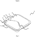
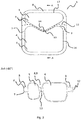
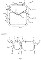
- the pouch is multi-chamber, meaning it has at least two chambers for holding product.
- the pouch is formed by a first film and a second film overlapping with the first film.
- the films are joined together, the join area is called seam.
- the seam comprises a first closed path within which space between the first film and the second film defines a first chamber for holding product.
- the seam further comprises a second closed path within which space between the first film and the second film defines a second chamber for holding product.
- the product is held in a chamber defined by the first film and the second film, which are joined together as closed path by the seam.
- the first film and second film each preferably comprises a form of polyvinyl alcohol, or derivatives thereof, which can easily dissolve in water.
- Such films are available, for example, from Mondi, Monosol, Nippon Gohsei, Aicello, Aquafilm, Kuraray.
- the product contained in the pouch may be liquid or solid.
- Liquid includes low viscosity liquids ( ⁇ 10mPas), high viscosity liquids (>10mPas), pasteous or gel like formulation, preferably flowable under normal pressure at 20°C.
- solid products powder, granulate, compressed granulate, tab, solidified melt.
- the solid is a granulate, this gives a faster dispersion and dissolution in water.
- the viscosity is the shear viscosity measured at 10 Hz under normal ambient pressure at 20°C.
- the products of each chamber together form a laundry composition.
- a preferred laundry composition comprises at least one solid composition as a product and at least one liquid composition as a product, whereas said at least one liquid composition and the at least one solid composition reside in different chambers of the pouch of this invention.
- the solid composition comprises a total amount of 0 to 5 wt.% surfactant.
- a particularly preferred pouch comprises
- a most preferred pouch comprises a) and b).
- Matter e.g. a compound or a composition
- Matter is defined as a liquid, if it is in the liquid state at 25°C, 1013 mbar.
- Matter e.g. a compound or a composition
- Matter is defined as a solid, if it is in the solid state at 25°C, 1013 mbar.
- a chemical compound is defined to be an organic compound, if said compound comprises a covalent bond between carbon and hydrogen. Said definition for example holds for organic bleach activators.
- a chemical compound is defined to be an inorganic compound, if said compound does not comprise a covalent bond between carbon and hydrogen. Said definition for example holds for inorganic peroxide compounds.
- a peroxide compound is a chemical compound, which comprises the peroxy-structural unit -O-O- in the molecule.
- a preferred solid composition comprises a total amount of 30 to 50 wt.%, particularly preferred from 33 to 45 wt.% peroxide compound.
- the solid composition preferably comprises above defined total amounts (and preferred total amounts) of at least one inorganic peroxide compound.
- Suitable peroxide compounds are especially percarbonate compounds, perborate compounds, peroxodisulfate compounds, hydrogen peroxide, addition compounds of hydrogen peroxide with inorganic compounds, organic peracids and mixtures thereof. It is preferred to select the peroxy compound from sodium percarbonate, sodium perborate, sodium peroxodisulfate or mixtures thereof.
- Sodium percarbonate is particularly preferred. Sodium percarbonate is an addition compound of hydrogen peroxide with sodium carbonate and obeys the formula yNa 2 CO 3 ⁇ xH 2 O 2 , whereas x is the molar amount of hydrogen peroxide per y mole of Na 2 CO 3 . Most preferred is sodium percarbonate with the formula Na 2 CO 3 ⁇ 1.5 H 2 O 2 (CAS-number 15630-89-4).
- the peroxide compound used according to this invention preferably has an amount of active oxygen between 9,0 and 15,0 %, especially from 10 to 14 % (determined by titration with potassium permanganate respectively).
- a particularly preferred peroxide compound comprises of particles of a solid, e.g. a granulate or a powder, and said particles have a bulk density of 0,70 to 1,30 kg/dm 3 , especially of 0,85 to 1,20 kg/dm 3 (determined using ISO 697 respectively).
- a bleach activator is a chemical compound enhancing the bleaching capability of the peroxide compound.
- the solid composition of said pouch comprises preferably a total amount of bleach activator of 11 to 18 wt%, more preferred 12 to 16 wt.%, even more preferred 10 to 15 wt%, and most preferred 11 to 14 wt.% .
- Preferred organic bleach activators yield via perhydrolysis organic peroxy acids, especially aliphatic organic percarboxylic acid with preferably 1 to 10 carbon atoms (more preferably 2 to 4 carbon atoms) and/or perbenzoic acid derivatives.
- Solid compositions comprising an organic bleach activator selected from at least one compound, which is capable of forming via perhydrolysis an aliphatic percarboxylic acid, are preferred. It is particularly preferred to select at least one organic bleach activator from N-acylated organic amine compounds. Said before mentioned total amounts are also preferably valid for said preferred organic bleach activators.
- the perhydrolysis reaction is a known chemical reaction. During perhydrolysis the anion -O-O-H covalently binds via nucleophilic substitution at reactant R-X yielding the compound R-O-O-H, while a leaving group X - separates by breaking the covalent bond between R and X.
- Most preferred organic bleachactivators are selected from multi acetylated alkylene diamines, especially tetraacetyl-ethylenediamine (TAED), acylated triazine compounds, especially 1,5-diacetyl-2,4-dioxohexahydro-1,3,5-triazine (DADHT), acyated glykoluriles, especially tetraacetylglykoluril (TAGU), N-acylimides, especially N-nonanoylsuccinimide (NOSI), acylated phenol sulfonates, especially n-nonanoyloxy- or isononanoyloxy-benzene sulfonate (n- notch. iso-NOBS). Said before mentioned total amounts are also preferably valid for said preferred organic bleach activators.
- TAED tetraacetyl-ethylenediamine
- DADHT 1,5-diacetyl-2,4-dio
- compositions of the pouch comprise as a bleaching system
- the total amount of surfactant of said solid composition is 0 to 4 wt.%, more preferred 0 to 0,5 wt.%, related to the total weight of said solid composition respectively. Most preferred the solid composition is surfactant free.
- soap is defined as the sodium or potassium salts of saturated or unsaturated fatty acids with 10 to 20 carbon atoms, of resin acids of colophony and of naphthenic acids. Sodium or potassium salts of fatty acids with 10 to 20 carbon atoms, especially with 12 to 18 carbon atoms, are particularly preferred soaps.
- the liquid composition of said pouch comprises preferably at least one anionic surfactant and at least one nonionic surfactant. Particularly preferred said surfactants are comprised in above mentioned total amounts in the liquid composition of said pouch.
- Suitable anionic surfactants comprise alkylbenzenesulfonic acid salts, olefinsulfonic acid salts, C12-18 alkanesulfonic acid salts, salts of sulfuric acid monoesters with a fatty alcohol, a fatty acid soap, salts of sulfuric acid monoesters with an ethoxylated fatty alcohol or a mixture of two or more of these anionic surfactants.
- alkylbenzenesulfonic acid salts, fatty acid soaps, salts of sulfuric acid monoesters with an ethoxylated fatty alcohol and mixtures thereof are more preferred.
- the total amount of anionic surfactant is preferably from 30 to 40 wt.% related to the total weight of the liquid composition.
- Surfactants of the sulfonate type which may here preferably be considered are C9-13 alkylbenzenesulfonates, olefinsulfonates, i.e. mixtures of alkenesulfonates and hydroxyalkanesulfonates and disulfonates, as are obtained, for example, from C12-18 monoolefins with a terminal or internal double bond by sulfonation with gaseous sulfur trioxide and subsequent alkaline or acidic hydrolysis of the sulfonation products.
- esters of ⁇ -sulfofatty acids for example the ⁇ -sulfonated methyl esters of hydrogenated coconut, palm kernel or tallow fatty acids, are also suitable.
- Preferred alk(en)ylsulfates are the salts of sulfuric acid semi-esters of C12-C18 fatty alcohols for example prepared from coco fatty alcohol, tallow fatty alcohol, lauryl, myristyl, cetyl or stearyl alcohol or C10-C20 oxo alcohols and those semi-esters of secondary alcohols of these chain lengths.
- C12-C16 alkylsulfates and C12-C15 alkylsulfates and C14-C15 alkylsulfates are preferred because of their washing characteristics.
- 2,3-Alkylsulfates are also suitable anionic surfactants.
- the sulfuric acid monoesters of straight-chain or branched C7-21 alcohols ethoxylated with 1 to 6 mol of ethylene oxide are also suitable, such as 2-methyl-branched C9-11 alcohols with on average 3.5 mol ethylene oxide (EO) or C12-18 fatty alcohols with 1 to 4 EO.
- Fatty acid soaps are further suitable anionic surfactants.
- Saturated and unsaturated fatty acid soaps are in particular suitable, such as the salts of lauric acid, myristic acid, palmitic acid, stearic acid, (hydrogenated) erucic acid and behenic acid and in particular soap mixtures derived from natural fatty acids, for example coconut, palm kernel, olive oil or tallow fatty acids.
- the anionic surfactants including the fatty acid soaps may be present in the form of the sodium, potassium, magnesium or ammonium salts thereof.
- the anionic surfactants are preferably present in the form of the sodium or ammonium salts thereof.
- Amines usable for neutralization to yield ammonium salts are preferably choline, triethylamine, monoethanolamine, diethanolamine, triethanolamine, methylethylamine or a mixture thereof, wherein monoethanolamine is preferred.
- a particularly preferred liquid composition comprises at least one anionic surfactant and at least one nonionic surfactant.
- the liquid composition comprises above mentioned amounts of anionic and nonionic surfactant respectively.
- Suitable nonionic surfactants include alkoxylated fatty alcohols, alkoxylated fatty acid alkyl esters, fatty acid amides, alkoxylated fatty acid amides, polyhydroxyfatty acid amides, alkylphenol polyglycol ethers, amine oxides, alkyl polyglucosides and mixtures thereof.
- alkoxylated fatty alcohols are ethoxylated, in particular primary alcohols with preferably 8 to 18 C atoms and on average 4 to 12 mol ethylene oxide (EO) per mol alcohol, in which the alcohol residue is linear or branched.
- EO ethylene oxide
- alcohol ethoxylates with 12 to 18 C atoms for example prepared from coconut, palm, tallow fat or oleyl alcohol, and on average 5 to 8 EO per mol of alcohol are preferred.
- Preferred ethoxylated alcohols include, for example, C 12-14 alcohols with 4 EO or 7 EO, C 9-11 alcohol with 7 EO, C 12-18 alcohols with 5 EO or 7 EO and mixtures of these.
- the stated degrees of ethoxylation are statistical averages which, for a specific product, may be an integer or a fractional number.
- Preferred alcohol ethoxylates have a narrow homologue distribution (narrow range ethoxylates, NRE).
- fatty alcohols with more than 12 EO may also be used. Examples of these are tallow fatty alcohol with 14 EO, 25 EO, 30 EO or 40 EO.
- Nonionic surfactants containing EO and PO groups together in one molecule may also be used according to the invention.
- the total amount of nonionic surfactants is preferably 18 to 28 wt.% related to the total weight of liquid detergent composition.
- a particularly preferred liquid composition comprises related to the total weight of liquid detergent
- a most preferred liquid composition comprises related to the total weight of liquid detergent
- a most preferred pouch comprises
- Seam is made by sealing as explained further below. Another word for seam is sealing region.
- the thickness of the seam is the thickness of the first and second film joined together after the sealing process step, which is typically less than the sum of the nominal thicknesses of the first film and second film before the sealing process step.
- the first film and the second film can each have a thickness of 100 ⁇ m when delivered, usually in a roll.
- the superposed films in the seam area, before the seam is formed have a total thickness of 200 ⁇ m, after joining the films together, for example by heating and pressing them together melt-joining them, the final thickness, which is the thickness of the seam , may be 150 ⁇ m, due to the applied pressure.
- the seam is a tight sealing such that the chamber is able to hold product in the chamber; for the avoidance of doubt, the seam most preferably does not have stitches.
- the seam also comprises a weakened line.
- the weakened line is characterized by a line in the seam in which can dissolve first when in contact with enough water, optionally that line can be used to tear the pouch apart.
- the thickness of the weakened line is less than the thickness of each of the first film and the second film combined so that the weakened line dissolves first when in contact with water, separating the first chamber from the second chamber.
- a thickness profile extending from the first chamber to the second chamber would have the thickness of the seam, a trench which is part of the weakened line and as a lower thickness than the thickness of the seam (the thickness of the weakened line), followed by the thickness of the seam.
- the weakened line is continuous and uninterrupted; the continuity gives the best separation of the first and/or second chamber. Uninterrupted means that there is no through hole in the weakened line, this assures that the pouch is still resistant enough to normal handling.
- the trench of the weakened line can be formed on both sides of the seam, or it can also be formed on one side as only. It can be more or less pronounced.
- the weakened line has a total film thickness of about one third of the seam thickness.
- a second, third, or higher order weakened line can have, and preferably has, the same characteristics analogous to the weakened line as described herein.
- the thickness ratio between the seam out of the weakened line and at the weakened line is 3.
- the thickness can be measured by any adequate means, since such thickness in the micrometer range can be determined with high accuracy by different techniques, as long as the measurement equipment is correctly calibrated.
- the thickness is measured by computer tomography on a pouch produced wherein the chambers are filled with air and no product, obviously without perforations in the chamber.
- Other exemplary methods are via profilometer, ellipsometry, microscopy of transversal cut.
- the first chamber has a lower density than the second chamber. It is further preferred that the first chamber comprises a liquid product, and the second chamber a solid product. Furthermore, the second chamber with a solid product has is preferably 100% filled, for that the chamber may comprise perforations or other means of venting, so that after sealing with the second film, the excess of air can be let out. Perforations are preferred as they can be made in a plurality and being very small so that, e.g., a grain of the granulate cannot escape the chamber. For the second chamber, 100% filled means that there is no air, such as an air bubble, other than the remaining air in the voids between the grains or the powder.
- the first chamber comprising a liquid may be less than 100% filled with liquid product, such that the remaining volume is occupied by air, this volume of air can be varied to adjust the desired density.
- the first chamber has a density lower than water and the second chamber has a density higher than water.
- the chambers are subject to different Beyonce forces, and there is a net result force pulling the first and the second chamber apart from each other. This net force helps to accelerate the separation of the chambers in addition to the dissolution of the weakened line in water. This has shown to result in excellent dispersion of the products from the first and the second chamber in the washing and/or cleaning liquor, especially in the washing liquor of a laundry washing machine.
- one of the first chamber or the second chamber comprises a concave section
- the other one comprises a convex section, which extends into the concave section. Since the first chamber is attached to the second chamber via the seam area between both (the bridge), the concave section can hold the convex section in place, effectively fixing the position of the first and the second chambers in relation to each other. It is thus possible to obtain a pouch with a first chamber and a second chamber, which is structurally stable, even with the presence of the weakened line. This effect is more pronounced when each of the first and second chambers is itself rigid.
- Rigid means for a chamber filled with liquid product, that it is filled with product and air such that the first and second films are kept under tension.
- rigid means as well that the chamber is filled with product and air such that the first and second films are kept under tension, or if perforated, that the solid product occupied large portion of the chamber in a sufficiently compact manner.
- the first chamber comprises the concave section and the second chamber comprises the convex section, which extends into the concave section of the first chamber.
- the convex and concave sections are geometrically complementary to each other, therefore obtaining best structural stability of the pouch.
- first chamber has the shape of a closed tube, which surrounds the second chamber.
- second chamber could be disc like and be made within the inner circle of a ring shaped outer chamber, thus looking like a swim ring.
- the sealing is made by pressing the first film and the second film together between a tool and a die.
- the tool is the outer surface of the mould, this surface is preferably flat, without sharp edges but preferably rounded edges, and optionally with a soft layer such as a rubber layer.
- the films can be glued or melted together. Melting is preferred and is named herein as heat sealing.
- a preferred method of sealing is heat sealing, wherein at least one of the tool and the die, preferably the die, is heated to soften the first film and the second film.
- the die can be a movable part external to the mould, preferably the surface of the die which is oriented towards the tool is flat and more preferably parallel to the tool.
- the surface of the die which is oriented towards the tool has a thermal greater than 1 Wm -1 K -1 , preferably greater than 10 Wm -1 K -1 (at 20°C under normal pressure). This allows for a good heat transfer when the films are sealed together by means of heat sealing.
- the surface can be made of a metal such as copper or a metal allow such as stainless steel.
- the surface can be coated with a very thin layer of e.g. a fluorinated polymer, as long as the heat transfer properties are not affected.
- the die's surface conforms to the pouch geometry, such as in Fig. 4 .
- the die needs to be able to contact the first film in the whole sealing area to form the seam and so that the weakened line is formed as a continuous line.
- the die may have cavities corresponding to the chambers, such that the die is able to contact the film in the sealing area but does not contact the chamber walls.
- the die is preferably stamp like.
- the die is a wheel that can be rolled over the films to form the seam, such can be used for instance for straight seams.
- the die is such that the complete seam of the pouch can be formed at once by sealing the first film to the second film.
- a stamp like dye is preferred for pouches with curved seams, such when one of the first chamber or the second chamber comprises a concave section, and the other one comprises a convex section, which extends into the concave section.
- curved seams can be made easier and in more reliable manner than with a wheel die.
- the weakened line is formed, for instance, by pressing, stamping, or embossing the seam between a tool and a die.
- the tool is the outer surface of the mould, this surface is preferably flat, without sharp edges but preferably rounded edges, and optionally with a soft layer such as a rubber layer.
- the die is a movable part external to the mould, preferably the surface of the die which is oriented towards the tool is flat.
- the die comprises a protrusion able to form the trench in the weakened line. While with such a protrusion it is possible to make sure that a weakened line is formed.
- the surface of the die which is oriented towards the tool is flat, the weakened line is formed by pressing the films between tool and die, the weakened line is formed due to the pressure distribution in the film.
- the weakened line is formed in step (v) at the same time of the sealing, thus the tool and die used for sealing also provide the weakened line. It is more preferred to form the weakened line in step (v) at the same time of the sealing, using a stamp like die, this provides the most efficient process and the most reliable results.
- the pouches produced in a process according to the present invention could be used in a process for separating an amount of product from the first chamber from an amount of product from the second chamber from a pouch produced according to the invention.
- This process comprises the steps of:
- a first film with a thickness of 90micrometers of PVA (specs) is positioned over a mould comprising two cavities as in Fig1 . and Fig. 2 , the outer base area is 60 mm x 60 mm.
- the first film is preheated by a contact plate to 100°C.
- the film is held fixed at the outer mould area (tool surface) and vacuum is applied in the mould through vacuum means present in the mould, thus deep drawing the first film in the mould.
- the volume of that the cavity which is going to form the first chamber is 18 cm3.
- the volume of the cavity which is going to form the second chamber is 9 cm3.
- the mould is transported to a subsequent station, in which the first cavity is filled to 90% of its volume with a liquid product with the formulation F1 below.
- the second cavity is filled to 90% of its volume with a solid product.
- the second film with same specs as the first film is drawn over the first film.
- a die having the same form of the mould and heated up to a temperature of 154 °C is pressed over the second film at a pressure of 0,5 N/mm 2 for 1100 ms.
- the die has a protruding line at its surface with a height of 30 micrometers, a width of 300 micrometers and a length sufficient to form a line crossing the pouch in the bridge area from one side to another, alternatively the die could have a protruding line able to make a weakened line around the first chamber, and another one around the second chamber.
- the films melt together and the weakened line is formed by this process at the immediate vicinity of the chamber wall in the seam.
- the die is removed, the pouch is let cool down for 30 seconds and is the vacuum is broken so that the pouch can be removed from the mould.
- a first film with a thickness of 90 micrometers of PVA (specs) is positioned over a mould comprising two cavities as in Fig. 1 . and Fig. 2 , the outer base area is 60mm x 60mm.
- the first film is kept at a temperature of 100 °C.
- the film is held fixed at the outer mould area (tool surface) and vaccum is applied in the mould through vacuum means present in the mould, thus deep drawing the first film in the mould.
- the volume of that the cavity which is going to form the first chamber is 18 cm3.
- the volume of the cavity which is going to form the second chamber is 9 cm3.
- the mould is transported to a subsequent station, in which the first cavity is filled to 90% of its volume with a liquid product with the formulation F1 below.
- the second cavity is filled to 90% of its volume with a powder granulate.
- the second film with same specs as the first film is drawn over the first film.
- a die having the same form of the mould and heated up to a temperature of 154 °C is pressed over the second film at a pressure of 1 N/mm 2 a for 1100 ms.
- the films melt together and the weakened line is formed by this process at the immediate vicinity of the chamber wall in the seam.
- the time is adjusted such that heated film flows by itself into two directions, between the die and the tool, and to the chamber wall (here the film is pulled by remaining tension from the deep drawing), thus the weakened line is formed by this process around the chamber.
- the die is removed, the pouch is let cool down for 30 seconds and is the vacuum is broken so that the pouch can be removed from the mould.
- the final thickness achieved by this method in the area of the seam is approximately 100 micrometers of (seam thickness), and about 45 micrometers of thickness of the weakened line.
- a solubility test was made for a pouch with a first chamber comprising liquid product and a second chamber comprising a granulate and small perforations in the top film.
- the pouch was placed in a cup with 200 ml of water at 20°C.
- the second chamber released its content at about 7 s, starting to release the granulate, the chambers were separated from each other after about 18 s.
- the first chamber separated from the rest of the pouch due to the dissolution of the weakened line, was still intact. Similar results could be reproduced with larger or smaller amounts of water, or using light agitation.
- a comparative example was made by producing a pouch as in example 2 but wherein the seam did not comprise a weakened line.
- the pouch was produced as in the example 2 with the difference that the sealing was done by pressing the die over the second film at a pressure of 0,5 N/mm 2 for 1100 ms.
- the solubility test when no weakened line is available, the chambers are still connected to the pouch when they break releasing the product. Thus, the product of the first chamber and of the second chamber are released in the proximity of the pouch. Consequently immediate physical or chemical interaction cannot be avoided, for instance, the liquid of the first chamber can coat the particles of the product of the second chamber so that the solubility of the particles is slowed down.
- Figure 1 shows a pouch 1 according to the present invention, in perspective view.
- Figure 2 shows the same pouch as Fig.1 , in top view, i.e., by looking onto first film 6.
- the pouch comprises a first film 6 and a second film 7 overlapping with the first film 6.
- the first film 6 and the second film 7 are joined together forming a seam 8.
- the pouch 1 comprises a first chamber 4 and a second chamber 5.
- the bridge 9 between the chambers 4, 5 is part of the seam 8.
- the seam 8 comprises a first closed path 16, refer to Fig. 2 and a second closed path 17, refer to Fig. 2 , which, in this example, are both right adjacent to the respective chamber wall.
- the space between the first film 6 and the second film 7 delimited by the first closed path 16 defines a first chamber 4 for holding product.
- the space between the first film 6 and the second film 7 delimited by the second closed path 17 defines a second chamber 5 for holding product.
- the seam 8 of the pouch of Figures 1 and 2 comprises a weakened line 13 dividing the pouch in one side with the first chamber 4 and into another side with the second chamber 5.
- the weakened line 13 is shown as a dashed line because such is easier to show in the Figure; nevertheless, it is highly preferred throughout the invention, that the weakened line 13 is continuous and uninterrupted.
- the thickness of the weakened line 13 is less than the thickness of each of the first film 6 and the second film 7 combined, so that the weakened line 13 dissolves first when in contact with water, separating the first chamber 4 from the second chamber 5.
- the first chamber 4 comprises a concave section 14, and the second chamber 5 comprises a convex section 15, which extends into the concave section 14.
- this view is the same as the plan view in the film plane (base area). Since the first chamber 4 is attached to the second chamber 5 via the bridge 9, the concave section 14 can hold the convex section 15 in place, effectively fixing the position of the first and the second chambers 4, 5 in relation to each other.
- the convex and concave sections are geometrically complementary to each other.
- Cross-section A-A shows a cut from the pouch of Fig.2 on line A-A, rotated by -90°.
- the film thicknesses are exaggerated in the seam region, in relation to the chamber wall and to the pouch size itself, for improving the clarity of the drawing, thus it is not on scale.
- the second chamber 5 can be seen on the right side connected to the first chamber 4 via the bridge 9.
- the seam 8 is shown and the sum 12 of thickness of the first film and second film in the seam 8.
- the thickness 12 of the seam 8 is the thickness of the first and second film joined together after the sealing process step, which is typically less than the sum of the nominal thicknesses of the first film 6 and second film 7 before the sealing process step.
- the first film 6 and the second film 7 can each have a thickness of 100 ⁇ m when delivered, usually in a roll.
- the weakened line 13 has a trench form and divides the pouch in a part with the first chamber 4 and a part with the second chamber 5.
- the trench is shown on both sides of the seam 8, but can be formed on one side as well, it can also be less pronounced as shown, as long as the film has this thinner region.
- the weakened line 13 has a total film thickness of about one third of the seam thickness 12.
- the wall of the chamber may be thinner than the film thickness (as delivered), for example due to a thinning caused by deep drawing.
- Figure 3 shows a similar pouch 1 as in Figure 2 but with a different configuration of the weakened line 13.
- the pouch 1 comprises a weakened line 13 circumventing the first chamber 4, and a second weakened line 29 circumventing the second chamber 5.
- the cross sectional cut can B-B is also shown in Figure 3 , it is rotated by -90°.
- the film thicknesses are exaggerated in the seam region, in relation to the chamber wall and to the pouch size itself, for improving the clarity of the drawing, thus it is not on scale.
- the second chamber 5 can be seen on the right side connected to the first chamber 4 via the bridge 9.
- the seam 8 is shown and the sum 12 of thickness of the first film and second film in the seam 8.
- the thickness 12 of the seam 8 is the thickness of the first and second film joined together after the sealing process step, which is typically less than the sum of the nominal thicknesses of the first film and second film before the sealing process step.
- the first film 6 and the second film 7 can each have a thickness of 100 ⁇ m when delivered, usually in a roll.
- the weakened line 13 has a trench form circumventing the first chamber 4. The trench is shown on both sides of the seam, but can be formed on one side as well, it can also be less pronounced as shown, as long as the film has this thinner region.
- a second weakened line 29 has the same trench form and circumvents the second chamber 5. Each of the weakened line 13 and the second weakened line 29 has a total film thickness of about one third of the seam thickness 12.
- Fig. 4 shows a mould 21, its lateral surface forming the tool and the die for sealing.
- the tool and die are preferably also used for creating the weakened line.
- the lower part is a cross-section cut of the mould 21 with a first and a second cavity 22.
- the surface 30 of the mould 21 at the side of the cavity forms the tool 30 for sealing.
- This tool 30 is preferably also the tool for creating the weakened line 13.
- the upper part of the Figure is a cross section view of the die 31, the die's surface matches to the tool's surface to create the seam 8.
- Fig.5 shows details of the tool 30 and die surfaces 31 and variants thereof.
- the tool 30 On the left side, it is shown the tool 30 with a surface layer and its rounded edges, over the tool, the die 31 is shown with rounded edges and same size as the tool.
- the die 31 In the middle Figure the die 31 is larger than the tool 30, this is advantageous to avoid alignment errors, so that the seam 8 is always formed between two parallel surfaces.
- the die In the Figure on the right side, the die has a protrusion 32, which is shown in an exaggerate scale, this protrusion is used to create the weakened line according to the invention.
Description
- The invention concerns a process for producing a water soluble pouch for holding a unitary dose of product.
- Water soluble pouches are well known in the art. They can have many uses, for instance as unitary doses for laundry washing machines or for dishwashing. Exemplary monochamber pouches are described in
EP1361172B1 .EP1361172B1 describes water soluble pouches having a dome shaped wall which is described as providing mechanical stability. The process of production of such mono and multichamber pouches is also well described in the literature. For instance,EP1360110B1 andWO2014/170882A1 each describe a process for producing water soluble pouches on a rotating platen conveyer belt. - The state of the art deals with the series production of pouches, the rotating platen conveyer belt can be moved on a horizontal manufacturing line or around a cylinder. Pouches produced by these methods are available and re know to be relatively robust for handling before submerging them in water.
- Further
WO03/031264A1 - Due to the robustness, these pouches tend to take some time to dissolve. However, with the use of always better washing and/or cleaning product formulations, and washing methods using less water, less power and being faster, it is necessary to dispense the products without delay. While some improvements of the state of the art are towards better watersoluble films, it is still desired to obtain a better release of products from multi-chamber pouches in the washing environment.
- The problem of the invention is to provide a method for producing a multi-chamber water soluble pouch with improved characteristics.
- This problem is solved by providing a process for producing a water soluble pouch according to the features of
claim 1. The dependent claims deal with further developments of the invention. - The present invention concerns a process for producing a water soluble pouch comprising:
- (i) providing a mould with a first cavity and a second cavity,
- (ii) providing a first film over the mould,
- (iii) deep drawing the first film into the first cavity of the mould forming an open first chamber and into the second cavity of the mould forming an open second chamber; preferably filling the first chamber and the second chamber with product;
- (iv) providing a second film over the, preferably filled, chambers;
- (v) a sealing step to form a seam which comprises joining the second film to the first film in the seam area therefore closing the first chamber and the second chamber, wherein the sealing step is preferably realized such that the resulting seam comprises a first closed path for the first chamber and a second closed path for the second chamber,
- (vi) forming of a weakened line in the seam such that at least the first chamber can be separated from the second chamber, wherein in the weakened line the thickness of the seam is reduced in at least one position between the first chamber and the second chamber, and wherein the weakened line is in form of a trench in the seam,
- In one preferred embodiment, the weakened line surrounds the first chamber and is preferably continuous and uninterrupted. In addition or alternative, a second weakened line surrounds the second chamber and is preferably continuous and uninterrupted. If the weakened line and the second weakened line are present, it is preferred that both, are made the same manner in the same process step.
- It is preferred that the first chamber is filled with a liquid product.
- The second chamber is preferably filled with a solid product.
- In one preferred embodiment of the invention, the second chamber is perforated before being filled. Alternatively, the film, preferably the second film, area that is to be used for the second chamber, is perforated before being placed over the chamber.
- The Pouch which is not a part of the present invention is water soluble, meaning that the first and second film react with water until they disappear releasing the pouches content, i.e. the product. The pouch is multi-chamber, meaning it has at least two chambers for holding product.
- The pouch is formed by a first film and a second film overlapping with the first film. The films are joined together, the join area is called seam. The seam comprises a first closed path within which space between the first film and the second film defines a first chamber for holding product. The seam further comprises a second closed path within which space between the first film and the second film defines a second chamber for holding product. Thus, in each case the product is held in a chamber defined by the first film and the second film, which are joined together as closed path by the seam.
- The first film and second film each preferably comprises a form of polyvinyl alcohol, or derivatives thereof, which can easily dissolve in water. Such films are available, for example, from Mondi, Monosol, Nippon Gohsei, Aicello, Aquafilm, Kuraray.
- The product contained in the pouch may be liquid or solid. Liquid includes low viscosity liquids (< 10mPas), high viscosity liquids (>10mPas), pasteous or gel like formulation, preferably flowable under normal pressure at 20°C. The following are examples of solid products: powder, granulate, compressed granulate, tab, solidified melt. Preferably the solid is a granulate, this gives a faster dispersion and dissolution in water.
- The viscosity is the shear viscosity measured at 10 Hz under normal ambient pressure at 20°C. Preferably, the products of each chamber together form a laundry composition.
- A preferred laundry composition comprises at least one solid composition as a product and at least one liquid composition as a product, whereas said at least one liquid composition and the at least one solid composition reside in different chambers of the pouch of this invention.
- It is highly preferred that the solid composition comprises a total amount of 0 to 5 wt.% surfactant.
- A particularly preferred pouch comprises
- a) in the first chamber a product in the form of a liquid composition, comprising related to the total weight of said liquid composition
- a total amount of 25 to 60 wt.-% of at least one anionic surfactant and
- a total amount of 2 to 35 wt.-% of at least one nonionic surfactant,
or/and
- b) in the second chamber a product in the form of a a solid composition, comprising related to the total weight of said solid composition
- a total amount of 25 to 55 wt.-% of at least one peroxide compound,
- a total amount of 2 to 25 wt.-% of at least one organic bleach activator,
- a total amount of 0 to 5 wt.-% surfactant.
- A most preferred pouch comprises a) and b).
- Matter (e.g. a compound or a composition) is defined as a liquid, if it is in the liquid state at 25°C, 1013 mbar.
- Matter (e.g. a compound or a composition) is defined as a solid, if it is in the solid state at 25°C, 1013 mbar.
- A chemical compound is defined to be an organic compound, if said compound comprises a covalent bond between carbon and hydrogen. Said definition for example holds for organic bleach activators.
- A chemical compound is defined to be an inorganic compound, if said compound does not comprise a covalent bond between carbon and hydrogen. Said definition for example holds for inorganic peroxide compounds.
- A peroxide compound is a chemical compound, which comprises the peroxy-structural unit -O-O- in the molecule. A preferred solid composition comprises a total amount of 30 to 50 wt.%, particularly preferred from 33 to 45 wt.% peroxide compound.
- The solid composition preferably comprises above defined total amounts (and preferred total amounts) of at least one inorganic peroxide compound.
- Suitable peroxide compounds are especially percarbonate compounds, perborate compounds, peroxodisulfate compounds, hydrogen peroxide, addition compounds of hydrogen peroxide with inorganic compounds, organic peracids and mixtures thereof. It is preferred to select the peroxy compound from sodium percarbonate, sodium perborate, sodium peroxodisulfate or mixtures thereof. Sodium percarbonate is particularly preferred. Sodium percarbonate is an addition compound of hydrogen peroxide with sodium carbonate and obeys the formula yNa2CO3·xH2O2, whereas x is the molar amount of hydrogen peroxide per y mole of Na2CO3. Most preferred is sodium percarbonate with the formula Na2CO3·1.5 H2O2 (CAS-number 15630-89-4).
- The peroxide compound used according to this invention preferably has an amount of active oxygen between 9,0 and 15,0 %, especially from 10 to 14 % (determined by titration with potassium permanganate respectively).
- A particularly preferred peroxide compound comprises of particles of a solid, e.g. a granulate or a powder, and said particles have a bulk density of 0,70 to 1,30 kg/dm3, especially of 0,85 to 1,20 kg/dm3 (determined using ISO 697 respectively).
- Furthermore it is preferred to use a peroxide compound having a mean particle size (volume weighted) X50,3 of 0,40 to 0,95 mm, especially from 0,50 to 0,90 mm (e.g. determined by mesh analysis or with a particle size analyser "Camsizer" of company Retsch).
- A bleach activator is a chemical compound enhancing the bleaching capability of the peroxide compound.
- The solid composition of said pouch comprises preferably a total amount of bleach activator of 11 to 18 wt%, more preferred 12 to 16 wt.%, even more preferred 10 to 15 wt%, and most preferred 11 to 14 wt.% .
- Preferred organic bleach activators yield via perhydrolysis organic peroxy acids, especially aliphatic organic percarboxylic acid with preferably 1 to 10 carbon atoms (more preferably 2 to 4 carbon atoms) and/or perbenzoic acid derivatives.
- Solid compositions, comprising an organic bleach activator selected from at least one compound, which is capable of forming via perhydrolysis an aliphatic percarboxylic acid, are preferred. It is particularly preferred to select at least one organic bleach activator from N-acylated organic amine compounds. Said before mentioned total amounts are also preferably valid for said preferred organic bleach activators.
- The perhydrolysis reaction is a known chemical reaction. During perhydrolysis the anion -O-O-H covalently binds via nucleophilic substitution at reactant R-X yielding the compound R-O-O-H, while a leaving group X- separates by breaking the covalent bond between R and X.
- Most preferred organic bleachactivators are selected from multi acetylated alkylene diamines, especially tetraacetyl-ethylenediamine (TAED), acylated triazine compounds, especially 1,5-diacetyl-2,4-dioxohexahydro-1,3,5-triazine (DADHT), acyated glykoluriles, especially tetraacetylglykoluril (TAGU), N-acylimides, especially N-nonanoylsuccinimide (NOSI), acylated phenol sulfonates, especially n-nonanoyloxy- or isononanoyloxy-benzene sulfonate (n- bzw. iso-NOBS). Said before mentioned total amounts are also preferably valid for said preferred organic bleach activators.
- Most preferred solid compositions of the pouch comprise as a bleaching system
- a total amount of 25 to 55 wt.-% (especially 30 to 50 wt.-%) of at least one inorganic peroxide compound (especially of sodium percarbonate), and
- a total amount of 10 to 20 wt.-% of at least one organic bleach activator, selected from at least one compound, which is capable of forming via perhydrolysis an aliphatic percarboxylic acid ( especially selected from at least N-acylated organic amine).
- It is particularly preferred, if the total amount of surfactant of said solid composition is 0 to 4 wt.%, more preferred 0 to 0,5 wt.%, related to the total weight of said solid composition respectively. Most preferred the solid composition is surfactant free.
- If surfactant is present in the solid composition it is an advantage use at least one soap. Soap is defined as the sodium or potassium salts of saturated or unsaturated fatty acids with 10 to 20 carbon atoms, of resin acids of colophony and of naphthenic acids. Sodium or potassium salts of fatty acids with 10 to 20 carbon atoms, especially with 12 to 18 carbon atoms, are particularly preferred soaps.
- The liquid composition of said pouch comprises preferably at least one anionic surfactant and at least one nonionic surfactant. Particularly preferred said surfactants are comprised in above mentioned total amounts in the liquid composition of said pouch.
- Suitable anionic surfactants comprise alkylbenzenesulfonic acid salts, olefinsulfonic acid salts, C12-18 alkanesulfonic acid salts, salts of sulfuric acid monoesters with a fatty alcohol, a fatty acid soap, salts of sulfuric acid monoesters with an ethoxylated fatty alcohol or a mixture of two or more of these anionic surfactants. Among these anionic surfactants, alkylbenzenesulfonic acid salts, fatty acid soaps, salts of sulfuric acid monoesters with an ethoxylated fatty alcohol and mixtures thereof are more preferred.
- The total amount of anionic surfactant is preferably from 30 to 40 wt.% related to the total weight of the liquid composition.
- Surfactants of the sulfonate type which may here preferably be considered are C9-13 alkylbenzenesulfonates, olefinsulfonates, i.e. mixtures of alkenesulfonates and hydroxyalkanesulfonates and disulfonates, as are obtained, for example, from C12-18 monoolefins with a terminal or internal double bond by sulfonation with gaseous sulfur trioxide and subsequent alkaline or acidic hydrolysis of the sulfonation products. C12-11 alkanesulfonates and the esters of α-sulfofatty acids (ester sulfonates), for example the α-sulfonated methyl esters of hydrogenated coconut, palm kernel or tallow fatty acids, are also suitable.
- Preferred alk(en)ylsulfates are the salts of sulfuric acid semi-esters of C12-C18 fatty alcohols for example prepared from coco fatty alcohol, tallow fatty alcohol, lauryl, myristyl, cetyl or stearyl alcohol or C10-C20 oxo alcohols and those semi-esters of secondary alcohols of these chain lengths. C12-C16 alkylsulfates and C12-C15 alkylsulfates and C14-C15 alkylsulfates are preferred because of their washing characteristics. 2,3-Alkylsulfates are also suitable anionic surfactants.
- The sulfuric acid monoesters of straight-chain or branched C7-21 alcohols ethoxylated with 1 to 6 mol of ethylene oxide are also suitable, such as 2-methyl-branched C9-11 alcohols with on average 3.5 mol ethylene oxide (EO) or C12-18 fatty alcohols with 1 to 4 EO.
- Fatty acid soaps are further suitable anionic surfactants. Saturated and unsaturated fatty acid soaps are in particular suitable, such as the salts of lauric acid, myristic acid, palmitic acid, stearic acid, (hydrogenated) erucic acid and behenic acid and in particular soap mixtures derived from natural fatty acids, for example coconut, palm kernel, olive oil or tallow fatty acids.
- The anionic surfactants including the fatty acid soaps may be present in the form of the sodium, potassium, magnesium or ammonium salts thereof. The anionic surfactants are preferably present in the form of the sodium or ammonium salts thereof. Amines usable for neutralization to yield ammonium salts are preferably choline, triethylamine, monoethanolamine, diethanolamine, triethanolamine, methylethylamine or a mixture thereof, wherein monoethanolamine is preferred.
- A particularly preferred liquid composition comprises at least one anionic surfactant and at least one nonionic surfactant. Preferably the liquid composition comprises above mentioned amounts of anionic and nonionic surfactant respectively.
- Suitable nonionic surfactants include alkoxylated fatty alcohols, alkoxylated fatty acid alkyl esters, fatty acid amides, alkoxylated fatty acid amides, polyhydroxyfatty acid amides, alkylphenol polyglycol ethers, amine oxides, alkyl polyglucosides and mixtures thereof.
- Preferably used alkoxylated fatty alcohols are ethoxylated, in particular primary alcohols with preferably 8 to 18 C atoms and on average 4 to 12 mol ethylene oxide (EO) per mol alcohol, in which the alcohol residue is linear or branched. In particular, alcohol ethoxylates with 12 to 18 C atoms, for example prepared from coconut, palm, tallow fat or oleyl alcohol, and on average 5 to 8 EO per mol of alcohol are preferred. Preferred ethoxylated alcohols include, for example, C12-14 alcohols with 4 EO or 7 EO, C9-11 alcohol with 7 EO, C12-18 alcohols with 5 EO or 7 EO and mixtures of these. The stated degrees of ethoxylation are statistical averages which, for a specific product, may be an integer or a fractional number. Preferred alcohol ethoxylates have a narrow homologue distribution (narrow range ethoxylates, NRE). In addition to these nonionic surfactants, fatty alcohols with more than 12 EO may also be used. Examples of these are tallow fatty alcohol with 14 EO, 25 EO, 30 EO or 40 EO. Nonionic surfactants containing EO and PO groups together in one molecule may also be used according to the invention. A mixture of a (relatively highly) branched ethoxylated fatty alcohol and an unbranched ethoxylated fatty alcohol, such as for example a mixture of a C16-18 fatty alcohol with 7 EO and 2-propylheptanol with 7 EO, is furthermore suitable.
- The total amount of nonionic surfactants is preferably 18 to 28 wt.% related to the total weight of liquid detergent composition.
- A particularly preferred liquid composition comprises related to the total weight of liquid detergent
- a total amount of 25 to 60 wt.-% (especially 30 to 40 wt.%) anionic surfactant, and
- a total amount of 2 to 35 Gew.-% (especially 18 to 28 wt.%) nonionic surfactant, whereas at least one alkoxylated alcohol with 8 to 18 carbon atoms and 4 to 12 mol ethyleneoxide (EO) per mole of said alcohol.
- A most preferred liquid composition comprises related to the total weight of liquid detergent
- a total amount of 25 to 60 wt.-% (especially 30 to 40 wt.%) anionic surfactant, whereas at least C9-13-alkylbenzene sulfonate is comprised, and
- a total amount of 2 to 35 Gew.-% (especially 18 to 28 wt.%) nonionic surfactant, whereas at least one alkoxylated alcohol with 8 to 18 carbon atoms and 4 to 12 mol ethyleneoxide (EO) per mole of said alcohol.
- A most preferred pouch comprises
- a) in the first chamber a product in the form of a liquid composition, comprising related to the total weight of said liquid composition
- a total amount of 25 to 60 wt.-% (especially 30 to 40 wt.%) anionic surfactant, and
- a total amount of 2 to 35 Gew.-% (especially 18 to 28 wt.%) nonionic surfactant, whereas at least one alkoxylated alcohol with 8 to 18 carbon atoms and 4 to 12 mol ethyleneoxide (EO) per mole of said alcohol.
and
- b) in the second chamber a product in the form of a solid composition, comprising related to the total weight of said solid composition
- a total amount of 25 to 55 wt.-% (especially 30 to 50 wt.-%) of at least one inorganic peroxide compound (especially of sodium percarbonate), and
- a total amount of 10 to 20 wt.-% of at least one organic bleach activator, selected from at least one compound, which is capable of forming via perhydrolysis an aliphatic percarboxylic acid ( especially selected from at least N-acylated organic amine),
- a total amount of 0 to 5 wt.-% surfactant.
- Seam is made by sealing as explained further below. Another word for seam is sealing region.
- The thickness of the seam is the thickness of the first and second film joined together after the sealing process step, which is typically less than the sum of the nominal thicknesses of the first film and second film before the sealing process step. For example the first film and the second film can each have a thickness of 100µm when delivered, usually in a roll. Then the superposed films in the seam area, before the seam is formed, have a total thickness of 200µm, after joining the films together, for example by heating and pressing them together melt-joining them, the final thickness, which is the thickness of the seam , may be 150µm, due to the applied pressure. The skilled in the art would understand that the seam is a tight sealing such that the chamber is able to hold product in the chamber; for the avoidance of doubt, the seam most preferably does not have stitches.
- The seam also comprises a weakened line. The weakened line is characterized by a line in the seam in which can dissolve first when in contact with enough water, optionally that line can be used to tear the pouch apart. The thickness of the weakened line is less than the thickness of each of the first film and the second film combined so that the weakened line dissolves first when in contact with water, separating the first chamber from the second chamber. Thus, a thickness profile extending from the first chamber to the second chamber would have the thickness of the seam, a trench which is part of the weakened line and as a lower thickness than the thickness of the seam (the thickness of the weakened line), followed by the thickness of the seam. Preferably, the weakened line is continuous and uninterrupted; the continuity gives the best separation of the first and/or second chamber. Uninterrupted means that there is no through hole in the weakened line, this assures that the pouch is still resistant enough to normal handling.
- The trench of the weakened line can be formed on both sides of the seam, or it can also be formed on one side as only. It can be more or less pronounced. Preferably, the weakened line has a total film thickness of about one third of the seam thickness.
- A second, third, or higher order weakened line can have, and preferably has, the same characteristics analogous to the weakened line as described herein.
- The thickness ratio between the seam out of the weakened line and at the weakened line is 3. The thickness can be measured by any adequate means, since such thickness in the micrometer range can be determined with high accuracy by different techniques, as long as the measurement equipment is correctly calibrated. Preferably, the thickness is measured by computer tomography on a pouch produced wherein the chambers are filled with air and no product, obviously without perforations in the chamber. Other exemplary methods are via profilometer, ellipsometry, microscopy of transversal cut.
- It is generally preferred that the first chamber has a lower density than the second chamber. It is further preferred that the first chamber comprises a liquid product, and the second chamber a solid product. Furthermore, the second chamber with a solid product has is preferably 100% filled, for that the chamber may comprise perforations or other means of venting, so that after sealing with the second film, the excess of air can be let out. Perforations are preferred as they can be made in a plurality and being very small so that, e.g., a grain of the granulate cannot escape the chamber. For the second chamber, 100% filled means that there is no air, such as an air bubble, other than the remaining air in the voids between the grains or the powder. The first chamber comprising a liquid may be less than 100% filled with liquid product, such that the remaining volume is occupied by air, this volume of air can be varied to adjust the desired density.
- In a particularly preferred embodiment, the first chamber has a density lower than water and the second chamber has a density higher than water. Thus, when in water, the chambers are subject to different Beyonce forces, and there is a net result force pulling the first and the second chamber apart from each other. This net force helps to accelerate the separation of the chambers in addition to the dissolution of the weakened line in water. This has shown to result in excellent dispersion of the products from the first and the second chamber in the washing and/or cleaning liquor, especially in the washing liquor of a laundry washing machine.
- In one further development of the invention, one of the first chamber or the second chamber comprises a concave section, and the other one comprises a convex section, which extends into the concave section. Since the first chamber is attached to the second chamber via the seam area between both (the bridge), the concave section can hold the convex section in place, effectively fixing the position of the first and the second chambers in relation to each other. It is thus possible to obtain a pouch with a first chamber and a second chamber, which is structurally stable, even with the presence of the weakened line. This effect is more pronounced when each of the first and second chambers is itself rigid. Rigid means for a chamber filled with liquid product, that it is filled with product and air such that the first and second films are kept under tension. For a chamber filled with a solid product, rigid means as well that the chamber is filled with product and air such that the first and second films are kept under tension, or if perforated, that the solid product occupied large portion of the chamber in a sufficiently compact manner.
- Preferably, the first chamber comprises the concave section and the second chamber comprises the convex section, which extends into the concave section of the first chamber. Alternatively or in addition, it is preferred that the convex and concave sections are geometrically complementary to each other, therefore obtaining best structural stability of the pouch.
- This encompasses also a pouch in which the first chamber has the shape of a closed tube, which surrounds the second chamber. As an example the second chamber could be disc like and be made within the inner circle of a ring shaped outer chamber, thus looking like a swim ring.
- The sealing is made by pressing the first film and the second film together between a tool and a die. The tool is the outer surface of the mould, this surface is preferably flat, without sharp edges but preferably rounded edges, and optionally with a soft layer such as a rubber layer. The films can be glued or melted together. Melting is preferred and is named herein as heat sealing.
- A preferred method of sealing is heat sealing, wherein at least one of the tool and the die, preferably the die, is heated to soften the first film and the second film. The die can be a movable part external to the mould, preferably the surface of the die which is oriented towards the tool is flat and more preferably parallel to the tool. Alternatively or preferably in addition, the surface of the die which is oriented towards the tool has a thermal greater than 1 Wm-1K-1, preferably greater than 10 Wm-1K-1 (at 20°C under normal pressure). This allows for a good heat transfer when the films are sealed together by means of heat sealing. For example, the surface can be made of a metal such as copper or a metal allow such as stainless steel. The surface can be coated with a very thin layer of e.g. a fluorinated polymer, as long as the heat transfer properties are not affected.
- It is preferred that the die's surface conforms to the pouch geometry, such as in
Fig. 4 . For instance, the die needs to be able to contact the first film in the whole sealing area to form the seam and so that the weakened line is formed as a continuous line. If the complete seam is formed at once, the die may have cavities corresponding to the chambers, such that the die is able to contact the film in the sealing area but does not contact the chamber walls. The die is preferably stamp like. - In an alternative, but less preferred embodiment, the die is a wheel that can be rolled over the films to form the seam, such can be used for instance for straight seams. However, it is preferred that the die is such that the complete seam of the pouch can be formed at once by sealing the first film to the second film. Also, a stamp like dye is preferred for pouches with curved seams, such when one of the first chamber or the second chamber comprises a concave section, and the other one comprises a convex section, which extends into the concave section. Such curved seams can be made easier and in more reliable manner than with a wheel die.
- The weakened line is formed, for instance, by pressing, stamping, or embossing the seam between a tool and a die. The tool is the outer surface of the mould, this surface is preferably flat, without sharp edges but preferably rounded edges, and optionally with a soft layer such as a rubber layer. The die is a movable part external to the mould, preferably the surface of the die which is oriented towards the tool is flat.
- In one embodiment of the invention, the die comprises a protrusion able to form the trench in the weakened line. While with such a protrusion it is possible to make sure that a weakened line is formed. In another embodiment, the surface of the die which is oriented towards the tool is flat, the weakened line is formed by pressing the films between tool and die, the weakened line is formed due to the pressure distribution in the film.
- The weakened line is formed in step (v) at the same time of the sealing, thus the tool and die used for sealing also provide the weakened line. It is more preferred to form the weakened line in step (v) at the same time of the sealing, using a stamp like die, this provides the most efficient process and the most reliable results.
- The pouches produced in a process according to the present invention could be used in a process for separating an amount of product from the first chamber from an amount of product from the second chamber from a pouch produced according to the invention. This process comprises the steps of:
- a) bringing the pouch in contact with sufficient water to dissolve at least the weakened line;
- b) waiting for sufficient time until the weakened line is dissolved but at least one of the first chamber and the second chamber is still sealed; and
- c) exerting a sufficient force to the pouch to move the at least one still sealed chamber, preferably the first chamber containing a liquid product, away from the remaining of the pouch.
With this process which is not forming part of the claimed invention, different variants resulting in different sub-products are possible, as described below:- p1. In one embodiment, both the first and the second chambers are hermetically closed chambers. They can be separated from each other without being broken for a certain time in water. Within a certain time they can even be removed from water, dried and re-used. The time in which the pouch can remain in water before any of the chamber disintegrates (i.e. breaks open releasing its content) can be set in the range of 20s to 200s for water at 20°C under normal pressure, for thickness of the first film and second film each between 40 and 300 micrometers and weakened line thickness of greater than 10 micrometers and smaller than <1/3 of the sum of the film thickness at the seam. In this embodiment, the first and second chambers (or more if more chambers) can be moved apart from each other and then each can release its product into the water avoiding a direct interaction of the products. This is an advantage because due to the distance, it can be avoided that the products interact creating a mixture which is not or badly soluble and/or dispersible in water. Such distance can be obtained, e.g. by the tumbling of a laundry washing machine.
- p2. In another embodiment, one chamber, preferably the first chamber, is a hermetically closed chamber for example containing liquid; and the second chamber comprises a solid and has venting means, such as small perforations. Preferably, in step c) the second chamber is already opened and the product is at least partially delivered out of the pouch. Due to the perforations, the second chamber opens relatively fast releasing its product into the water, a certain time before the second chamber breaks open. This time difference can be set easily in the range of 20s to 200s for water at 20°C under normal pressure, for thickness of the first film and second film each between 40 and 300 micrometers and weakened line thickness of greater than 10 micrometers and smaller than <1/3 of the sum of the film thickness at the seam. In this embodiment, the solid product is released into the water before the product of the first chamber is released, thus it is possible to release two (or more if more chambers) kinds of products and avoid a direct interaction of the products. This is an advantage because it avoids that the products interact creating a mixture which is not or badly soluble and/or dispersible in water.
- A first film with a thickness of 90micrometers of PVA (specs) is positioned over a mould comprising two cavities as in
Fig1 . andFig. 2 , the outer base area is 60 mm x 60 mm. The first film is preheated by a contact plate to 100°C. The film is held fixed at the outer mould area (tool surface) and vacuum is applied in the mould through vacuum means present in the mould, thus deep drawing the first film in the mould. The volume of that the cavity which is going to form the first chamber is 18 cm3. The volume of the cavity which is going to form the second chamber is 9 cm3. The mould is transported to a subsequent station, in which the first cavity is filled to 90% of its volume with a liquid product with the formulation F1 below. The second cavity is filled to 90% of its volume with a solid product. In a subsequent station, the second film with same specs as the first film is drawn over the first film. Thereafter a die having the same form of the mould and heated up to a temperature of 154 °C is pressed over the second film at a pressure of 0,5 N/mm2 for 1100 ms. The die has a protruding line at its surface with a height of 30 micrometers, a width of 300 micrometers and a length sufficient to form a line crossing the pouch in the bridge area from one side to another, alternatively the die could have a protruding line able to make a weakened line around the first chamber, and another one around the second chamber. The films melt together and the weakened line is formed by this process at the immediate vicinity of the chamber wall in the seam. The die is removed, the pouch is let cool down for 30 seconds and is the vacuum is broken so that the pouch can be removed from the mould. - A first film with a thickness of 90 micrometers of PVA (specs) is positioned over a mould comprising two cavities as in
Fig. 1 . andFig. 2 , the outer base area is 60mm x 60mm. The first film is kept at a temperature of 100 °C. The film is held fixed at the outer mould area (tool surface) and vaccum is applied in the mould through vacuum means present in the mould, thus deep drawing the first film in the mould. The volume of that the cavity which is going to form the first chamber is 18 cm3. The volume of the cavity which is going to form the second chamber is 9 cm3. The mould is transported to a subsequent station, in which the first cavity is filled to 90% of its volume with a liquid product with the formulation F1 below. The second cavity is filled to 90% of its volume with a powder granulate. In a subsequent station, the second film with same specs as the first film is drawn over the first film. Thereafter a die having the same form of the mould and heated up to a temperature of 154 °C is pressed over the second film at a pressure of 1 N/mm2 a for 1100 ms. The films melt together and the weakened line is formed by this process at the immediate vicinity of the chamber wall in the seam. In this example, the time is adjusted such that heated film flows by itself into two directions, between the die and the tool, and to the chamber wall (here the film is pulled by remaining tension from the deep drawing), thus the weakened line is formed by this process around the chamber. The die is removed, the pouch is let cool down for 30 seconds and is the vacuum is broken so that the pouch can be removed from the mould. - The final thickness achieved by this method in the area of the seam is approximately 100 micrometers of (seam thickness), and about 45 micrometers of thickness of the weakened line. A solubility test was made for a pouch with a first chamber comprising liquid product and a second chamber comprising a granulate and small perforations in the top film. The pouch was placed in a cup with 200 ml of water at 20°C. The second chamber released its content at about 7 s, starting to release the granulate, the chambers were separated from each other after about 18 s. Surprisingly, even after 107 s in water, the first chamber, separated from the rest of the pouch due to the dissolution of the weakened line, was still intact. Similar results could be reproduced with larger or smaller amounts of water, or using light agitation.
- Similar tests done with pouches comprising liquid product in the first chamber and liquid product in the second chamber. The result was that the first chamber and the second chamber were separated but still intact after in water for 15s, and 3 even longer, releasing its content after about 60 s.
- A comparative example was made by producing a pouch as in example 2 but wherein the seam did not comprise a weakened line. The pouch was produced as in the example 2 with the difference that the sealing was done by pressing the die over the second film at a pressure of 0,5 N/mm2 for 1100 ms. In the solubility test, when no weakened line is available, the chambers are still connected to the pouch when they break releasing the product. Thus, the product of the first chamber and of the second chamber are released in the proximity of the pouch. Consequently immediate physical or chemical interaction cannot be avoided, for instance, the liquid of the first chamber can coat the particles of the product of the second chamber so that the solubility of the particles is slowed down.
- The invention will be further with the following embodiments and figures. The figures show in:
-
Fig 1 , apouch 1 in perspective view, with a weakenedline 13; -
Fig. 2 , apouch 1 in top view on thefirst film 6 side, with a weakenedline 13, and the cross section cut A-A; -
Fig. 3 , apouch 1 in top view on thefirst film 6 side, with a weakenedline 13 and an additional weakened line (29), and the cross section cut B-B. -
Fig. 4 shows amould 21, its lateral surface forming the tool and the die for sealing. The tool and die are preferably also used for creating the weakened line. -
Fig.5 shows details of thetool 30 and diesurfaces 31 and variants thereof. -
Figure 1 shows apouch 1 according to the present invention, in perspective view.Figure 2 shows the same pouch asFig.1 , in top view, i.e., by looking ontofirst film 6. The pouch comprises afirst film 6 and asecond film 7 overlapping with thefirst film 6. Thefirst film 6 and thesecond film 7 are joined together forming aseam 8. Thepouch 1 comprises afirst chamber 4 and asecond chamber 5. Thebridge 9 between thechambers seam 8. Theseam 8 comprises a firstclosed path 16, refer toFig. 2 and a secondclosed path 17, refer toFig. 2 , which, in this example, are both right adjacent to the respective chamber wall. The space between thefirst film 6 and thesecond film 7 delimited by the firstclosed path 16 defines afirst chamber 4 for holding product. The space between thefirst film 6 and thesecond film 7 delimited by the secondclosed path 17 defines asecond chamber 5 for holding product. - The
seam 8 of the pouch ofFigures 1 and2 comprises a weakenedline 13 dividing the pouch in one side with thefirst chamber 4 and into another side with thesecond chamber 5. The weakenedline 13 is shown as a dashed line because such is easier to show in the Figure; nevertheless, it is highly preferred throughout the invention, that the weakenedline 13 is continuous and uninterrupted. - The thickness of the weakened
line 13 is less than the thickness of each of thefirst film 6 and thesecond film 7 combined, so that the weakenedline 13 dissolves first when in contact with water, separating thefirst chamber 4 from thesecond chamber 5. - In the top view in
Fig. 2 , it can be seen that thefirst chamber 4 comprises aconcave section 14, and thesecond chamber 5 comprises aconvex section 15, which extends into theconcave section 14. Incidentally, this view is the same as the plan view in the film plane (base area). Since thefirst chamber 4 is attached to thesecond chamber 5 via thebridge 9, theconcave section 14 can hold theconvex section 15 in place, effectively fixing the position of the first and thesecond chambers - Cross-section A-A shows a cut from the pouch of
Fig.2 on line A-A, rotated by -90°. The film thicknesses are exaggerated in the seam region, in relation to the chamber wall and to the pouch size itself, for improving the clarity of the drawing, thus it is not on scale. - In the cross sectional view A-A, the
second chamber 5 can be seen on the right side connected to thefirst chamber 4 via thebridge 9. Theseam 8 is shown and thesum 12 of thickness of the first film and second film in theseam 8. Thethickness 12 of theseam 8 is the thickness of the first and second film joined together after the sealing process step, which is typically less than the sum of the nominal thicknesses of thefirst film 6 andsecond film 7 before the sealing process step. For example thefirst film 6 and thesecond film 7 can each have a thickness of 100µm when delivered, usually in a roll. Then the superposed films in the seam area, before the seam is formed, have a total thickness of 200µm), after joining the films together, for example by heating and pressing them together melt-joining them, the final thickness, which is the thickness of theseam 12, may be 150µm), due to the applied pressure. In the present example inFigure 2 , the weakenedline 13 has a trench form and divides the pouch in a part with thefirst chamber 4 and a part with thesecond chamber 5. The trench is shown on both sides of theseam 8, but can be formed on one side as well, it can also be less pronounced as shown, as long as the film has this thinner region. The weakenedline 13 has a total film thickness of about one third of theseam thickness 12. - Obviously, the wall of the chamber may be thinner than the film thickness (as delivered), for example due to a thinning caused by deep drawing.
-
Figure 3 shows asimilar pouch 1 as inFigure 2 but with a different configuration of the weakenedline 13. InFigure 3 , thepouch 1 comprises a weakenedline 13 circumventing thefirst chamber 4, and a second weakenedline 29 circumventing thesecond chamber 5. - The cross sectional cut can B-B is also shown in
Figure 3 , it is rotated by -90°. The film thicknesses are exaggerated in the seam region, in relation to the chamber wall and to the pouch size itself, for improving the clarity of the drawing, thus it is not on scale. - In the cross-sectional view B-B, the
second chamber 5 can be seen on the right side connected to thefirst chamber 4 via thebridge 9. Theseam 8 is shown and thesum 12 of thickness of the first film and second film in theseam 8. Thethickness 12 of theseam 8 is the thickness of the first and second film joined together after the sealing process step, which is typically less than the sum of the nominal thicknesses of the first film and second film before the sealing process step. For example thefirst film 6 and thesecond film 7 can each have a thickness of 100µm when delivered, usually in a roll. Then the superposed films in the seam area, before the seam is formed, have a total thickness of 200µm), after joining the films together, for example by heating and pressing them together melt-joining them, the final thickness, which is the thickness of theseam 12, may be 150µm), due to the applied pressure. In the present example inFigure 3 , the weakenedline 13 has a trench form circumventing thefirst chamber 4. The trench is shown on both sides of the seam, but can be formed on one side as well, it can also be less pronounced as shown, as long as the film has this thinner region. A second weakenedline 29 has the same trench form and circumvents thesecond chamber 5. Each of the weakenedline 13 and the second weakenedline 29 has a total film thickness of about one third of theseam thickness 12. -
Fig. 4 shows amould 21, its lateral surface forming the tool and the die for sealing. The tool and die are preferably also used for creating the weakened line. The lower part is a cross-section cut of themould 21 with a first and asecond cavity 22. Thesurface 30 of themould 21 at the side of the cavity forms thetool 30 for sealing. Thistool 30 is preferably also the tool for creating the weakenedline 13. The upper part of the Figure is a cross section view of the die 31, the die's surface matches to the tool's surface to create theseam 8. -
Fig.5 shows details of thetool 30 and diesurfaces 31 and variants thereof. On the left side, it is shown thetool 30 with a surface layer and its rounded edges, over the tool, thedie 31 is shown with rounded edges and same size as the tool. In the middle Figure the die 31 is larger than thetool 30, this is advantageous to avoid alignment errors, so that theseam 8 is always formed between two parallel surfaces. In the Figure on the right side, the die has aprotrusion 32, which is shown in an exaggerate scale, this protrusion is used to create the weakened line according to the invention. - Unless otherwise provided, all parameters given are under normal conditions, for instance a temperature of 20°C and ambient pressure of 1 atm.
-
- 1
- pouch
- 4
- first chamber
- 5
- second chamber
- 6
- first film
- 7
- second film
- 8
- seam
- 9
- bridge
- 12
- sum of thicknesses of first film and second film at the seam after sealing
- 13
- weakened line
- 14
- concave section of first chamber
- 15
- convex section of second chamber
- 16
- first closed path
- 17
- second closed path
- 21
- mould
- 22
- cavity
- 29
- second weakened line
- 30
- tool surface
- 31
- die
- 32
- protrusion
the weakened line is formed in step (v) at the same time than the sealing, wherein a tool and a die used for sealing also provide the weakened line and the weakened line is formed in the seam by pressing the seam between the tool, which is the outer surface of the mould, and the die which is movable.
Claims (10)
- A process for producing a water soluble pouch (1) comprising:(i) providing a mould (21) for the pouch (1) with a first cavity and a second cavity,(ii) providing a first film (6) over the mould (21),(iii) deep drawing the first film (6) into the first cavity of the mould (21) forming an open first chamber (4) and into the second cavity of the mould (21) forming an open second chamber (5);(iv) providing a second film (7) over the, preferably filled, chambers (4, 5);(v) a sealing step to form a seam (8) which comprises joining the second film (7) to the first film (6) in the seam area therefore closing the first chamber (4) and the second chamber (5);(vi) forming a weakened line (13) in the seam (8) such that at least the first chamber (4) can be separated from the second chamber (5), wherein in the weakened line (13) the thickness of the seam (8) is reduced in at least one position between the first chamber (4) and the second chamber (5), and wherein the weakened line (13) is in form of a trench in the seam (8)characterized in that
the weakened line (13) is formed in step (v) at the same time than the sealing, wherein a tool (30) and a die (31) used for sealing also provide the weakened line (13) and the weakened line (13) is formed in the seam (8) by pressing the seam (8) between a tool (30), which is the outer surface of the mould (21), and the die (31) which is movable. - A process for producing a water soluble pouch (1) according to claim 1, wherein the weakened line (13) surrounds the first chamber (4).
- A process for producing a water soluble pouch (1) according to one of the previous claims, wherein a second weakened line (29) surrounds the second chamber (5).
- A process for producing a water soluble pouch (1) according to one of the previous claims, wherein the first chamber (4) is filled with a liquid product.
- A process for producing a water soluble pouch (1) according to one of the previous claims, wherein the second chamber (5) is filled with a solid product.
- A process for producing a water soluble pouch (1) according to one of the previous claims, wherein the second chamber (5) is perforated before being filled.
- A process for producing a water soluble pouch (1) according to one of the previous claims, wherein at least one of the tool (30) and the die (31) is heated to soften the first film (6) and the second film (7).
- A process for producing a water soluble pouch (1) according to one of the previous claims, wherein the die (31) comprises a protrusion (32) able to form the trench in the weakened line (13).
- A process for producing a water soluble pouch (1) according to one of the claims 1 to 7, wherein the die (31) and the tool (30) comprise each a smooth and protrusion free surface, surface, which during pressing are parallel to each other.
- A process for producing a water soluble pouch (1) according to one of the previous claims, wherein the die's (31) surface conforms to the pouch (1) geometry.
Priority Applications (1)
| Application Number | Priority Date | Filing Date | Title |
|---|---|---|---|
| PL15196323T PL3025848T3 (en) | 2014-11-26 | 2015-11-25 | Process for producing a water soluble pouch |
Applications Claiming Priority (1)
| Application Number | Priority Date | Filing Date | Title |
|---|---|---|---|
| DE102014224194 | 2014-11-26 |
Publications (2)
| Publication Number | Publication Date |
|---|---|
| EP3025848A1 EP3025848A1 (en) | 2016-06-01 |
| EP3025848B1 true EP3025848B1 (en) | 2018-09-19 |
Family
ID=54780081
Family Applications (1)
| Application Number | Title | Priority Date | Filing Date |
|---|---|---|---|
| EP15196323.8A Active EP3025848B1 (en) | 2014-11-26 | 2015-11-25 | Process for producing a water soluble pouch |
Country Status (3)
| Country | Link |
|---|---|
| EP (1) | EP3025848B1 (en) |
| ES (1) | ES2693343T3 (en) |
| PL (1) | PL3025848T3 (en) |
Cited By (1)
| Publication number | Priority date | Publication date | Assignee | Title |
|---|---|---|---|---|
| WO2024068523A1 (en) * | 2022-09-30 | 2024-04-04 | Boehringer Ingelheim Vetmedica Gmbh | Administration packaging, production apparatus and production method |
Families Citing this family (14)
| Publication number | Priority date | Publication date | Assignee | Title |
|---|---|---|---|---|
| BR112018069052B1 (en) | 2016-04-13 | 2023-02-23 | Monosol, Llc | WATER-SOLUBLE FILM, PACKAGING THAT USES FILM AND METHODS OF MANUFACTURING AND USE THEREOF |
| RU2704615C1 (en) | 2016-06-13 | 2019-10-30 | Дзе Проктер Энд Гэмбл Компани | Water-soluble articles with a single dose, made from a combination of different films and containing compositions for household use |
| US10745655B2 (en) | 2016-06-13 | 2020-08-18 | The Procter & Gamble Company | Water-soluble unit dose articles made from a combination of different films and containing household care compositions |
| CN109311574A (en) * | 2016-06-13 | 2019-02-05 | 蒙诺苏尔有限公司 | Water-soluble packet dress |
| EP3469060A1 (en) | 2016-06-13 | 2019-04-17 | The Procter & Gamble Company | Water-soluble unit dose articles made from a combination of different films and containing household care compositions |
| CA3025092A1 (en) | 2016-06-13 | 2017-12-21 | Monosol, Llc | Water-soluble unit dose articles made from a combination of different films |
| US10907117B2 (en) | 2016-06-13 | 2021-02-02 | Monosol, Llc | Use of a first film and a second film to improve seal strength of a water-soluble unit dose article |
| US10294445B2 (en) * | 2016-09-01 | 2019-05-21 | The Procter & Gamble Company | Process for making unitized dose pouches with modifications at a seal region |
| US11920014B2 (en) | 2017-05-19 | 2024-03-05 | Dow Global Technologies Llc | Sealing compositions for water soluble films and methods of using |
| EP3434758B1 (en) * | 2017-07-28 | 2022-05-25 | Henkel IP & Holding GmbH | Methods of making unit-dose products with supercooling |
| NL2019573B1 (en) * | 2017-09-19 | 2019-03-28 | Eme Engel Machf En Engineering B V | Pouched unit and method of using said pouched unit |
| US20220081656A1 (en) * | 2019-01-22 | 2022-03-17 | Reckitt Benckiser Finish B.V. | Method of forming an automatic dishwashing pouch, vacuum forming system and pouch |
| DE102019207162A1 (en) * | 2019-05-16 | 2020-11-19 | Henkel Ag & Co. Kgaa | Method for producing a portion unit of a detergent and portion unit |
| DE102021209931A1 (en) | 2021-09-08 | 2023-03-09 | Henkel Ag & Co. Kgaa | Process for the manufacture of detergent dosing units with improved properties |
Family Cites Families (6)
| Publication number | Priority date | Publication date | Assignee | Title |
|---|---|---|---|---|
| GB9906175D0 (en) | 1999-03-17 | 1999-05-12 | Unilever Plc | A water soluble package |
| MXPA03006883A (en) | 2001-01-31 | 2003-11-13 | Procter & Gamble | Process for making pouches. |
| DE10163254A1 (en) * | 2001-10-09 | 2003-07-17 | Henkel Kgaa | Multi-part blow molded body |
| FR2875222B1 (en) * | 2004-09-15 | 2006-12-22 | Salaisons De Broceliande Sa | ALVEOLAR PACKAGING FOR FOOD PRODUCT ROLL |
| CA2909375A1 (en) * | 2013-04-19 | 2014-10-23 | Rideau Machinery, Inc | Making water soluble pouches |
| DE102014206095A1 (en) * | 2014-03-31 | 2015-10-01 | Henkel Ag & Co. Kgaa | Water-reactive portion pack |
-
2015
- 2015-11-25 EP EP15196323.8A patent/EP3025848B1/en active Active
- 2015-11-25 ES ES15196323.8T patent/ES2693343T3/en active Active
- 2015-11-25 PL PL15196323T patent/PL3025848T3/en unknown
Non-Patent Citations (1)
| Title |
|---|
| None * |
Cited By (1)
| Publication number | Priority date | Publication date | Assignee | Title |
|---|---|---|---|---|
| WO2024068523A1 (en) * | 2022-09-30 | 2024-04-04 | Boehringer Ingelheim Vetmedica Gmbh | Administration packaging, production apparatus and production method |
Also Published As
| Publication number | Publication date |
|---|---|
| PL3025848T3 (en) | 2019-03-29 |
| EP3025848A1 (en) | 2016-06-01 |
| ES2693343T3 (en) | 2018-12-11 |
Similar Documents
| Publication | Publication Date | Title |
|---|---|---|
| EP3025848B1 (en) | Process for producing a water soluble pouch | |
| EP3025983B1 (en) | Water soluble pouch | |
| US9878484B2 (en) | Horizontal intermittent motion thermoforming machine | |
| EP1161382B1 (en) | Water soluble package | |
| RU2546651C2 (en) | Water-soluble film with improved solubility and improved mechanical properties, as well as packets, produced from it | |
| CA2420121C (en) | Water-soluble thermoformed containers comprising aqueous compositions | |
| AU2009342703B2 (en) | Injection moulded containers | |
| KR20180135442A (en) | Water-soluble films, packets using films, and methods of making and using them | |
| CA2420380C (en) | Water-soluble containers | |
| EP1400460B1 (en) | Water soluble package and liquid contents thereof | |
| US9546343B2 (en) | Low-water, liquid detergent having increased fat-dissolving power | |
| US20040209793A1 (en) | Encapsulated liquid detergent composition | |
| GB2367828A (en) | Water-soluble containers containing aqueous compositions | |
| RU2639866C2 (en) | Packaged detergent composition | |
| US20060293447A1 (en) | Water soluble package and for producing it | |
| DE102014206096A1 (en) | Process for the preparation of portion packs |
Legal Events
| Date | Code | Title | Description |
|---|---|---|---|
| PUAI | Public reference made under article 153(3) epc to a published international application that has entered the european phase |
Free format text: ORIGINAL CODE: 0009012 |
|
| 17P | Request for examination filed |
Effective date: 20151125 |
|
| AK | Designated contracting states |
Kind code of ref document: A1 Designated state(s): AL AT BE BG CH CY CZ DE DK EE ES FI FR GB GR HR HU IE IS IT LI LT LU LV MC MK MT NL NO PL PT RO RS SE SI SK SM TR |
|
| AX | Request for extension of the european patent |
Extension state: BA ME |
|
| 17Q | First examination report despatched |
Effective date: 20160518 |
|
| GRAP | Despatch of communication of intention to grant a patent |
Free format text: ORIGINAL CODE: EPIDOSNIGR1 |
|
| RIC1 | Information provided on ipc code assigned before grant |
Ipc: B65B 7/16 20060101ALI20180426BHEP Ipc: B65B 61/02 20060101ALI20180426BHEP Ipc: B29C 65/00 20060101AFI20180426BHEP Ipc: B65D 65/46 20060101ALI20180426BHEP Ipc: B29C 65/48 20060101ALN20180426BHEP Ipc: B29C 65/02 20060101ALN20180426BHEP Ipc: B65B 9/04 20060101ALI20180426BHEP Ipc: C11D 17/04 20060101ALI20180426BHEP Ipc: B65B 47/10 20060101ALI20180426BHEP Ipc: B65B 51/14 20060101ALI20180426BHEP Ipc: B65B 61/00 20060101ALI20180426BHEP Ipc: B65D 75/52 20060101ALI20180426BHEP Ipc: B29L 31/00 20060101ALN20180426BHEP |
|
| INTG | Intention to grant announced |
Effective date: 20180509 |
|
| GRAS | Grant fee paid |
Free format text: ORIGINAL CODE: EPIDOSNIGR3 |
|
| GRAA | (expected) grant |
Free format text: ORIGINAL CODE: 0009210 |
|
| AK | Designated contracting states |
Kind code of ref document: B1 Designated state(s): AL AT BE BG CH CY CZ DE DK EE ES FI FR GB GR HR HU IE IS IT LI LT LU LV MC MK MT NL NO PL PT RO RS SE SI SK SM TR |
|
| REG | Reference to a national code |
Ref country code: GB Ref legal event code: FG4D |
|
| REG | Reference to a national code |
Ref country code: CH Ref legal event code: EP |
|
| REG | Reference to a national code |
Ref country code: AT Ref legal event code: REF Ref document number: 1042752 Country of ref document: AT Kind code of ref document: T Effective date: 20181015 |
|
| REG | Reference to a national code |
Ref country code: IE Ref legal event code: FG4D |
|
| REG | Reference to a national code |
Ref country code: DE Ref legal event code: R096 Ref document number: 602015016562 Country of ref document: DE |
|
| REG | Reference to a national code |
Ref country code: ES Ref legal event code: FG2A Ref document number: 2693343 Country of ref document: ES Kind code of ref document: T3 Effective date: 20181211 |
|
| REG | Reference to a national code |
Ref country code: NL Ref legal event code: MP Effective date: 20180919 |
|
| PG25 | Lapsed in a contracting state [announced via postgrant information from national office to epo] |
Ref country code: LT Free format text: LAPSE BECAUSE OF FAILURE TO SUBMIT A TRANSLATION OF THE DESCRIPTION OR TO PAY THE FEE WITHIN THE PRESCRIBED TIME-LIMIT Effective date: 20180919 Ref country code: NO Free format text: LAPSE BECAUSE OF FAILURE TO SUBMIT A TRANSLATION OF THE DESCRIPTION OR TO PAY THE FEE WITHIN THE PRESCRIBED TIME-LIMIT Effective date: 20181219 Ref country code: RS Free format text: LAPSE BECAUSE OF FAILURE TO SUBMIT A TRANSLATION OF THE DESCRIPTION OR TO PAY THE FEE WITHIN THE PRESCRIBED TIME-LIMIT Effective date: 20180919 Ref country code: GR Free format text: LAPSE BECAUSE OF FAILURE TO SUBMIT A TRANSLATION OF THE DESCRIPTION OR TO PAY THE FEE WITHIN THE PRESCRIBED TIME-LIMIT Effective date: 20181220 Ref country code: BG Free format text: LAPSE BECAUSE OF FAILURE TO SUBMIT A TRANSLATION OF THE DESCRIPTION OR TO PAY THE FEE WITHIN THE PRESCRIBED TIME-LIMIT Effective date: 20181219 Ref country code: FI Free format text: LAPSE BECAUSE OF FAILURE TO SUBMIT A TRANSLATION OF THE DESCRIPTION OR TO PAY THE FEE WITHIN THE PRESCRIBED TIME-LIMIT Effective date: 20180919 Ref country code: SE Free format text: LAPSE BECAUSE OF FAILURE TO SUBMIT A TRANSLATION OF THE DESCRIPTION OR TO PAY THE FEE WITHIN THE PRESCRIBED TIME-LIMIT Effective date: 20180919 |
|
| REG | Reference to a national code |
Ref country code: LT Ref legal event code: MG4D |
|
| PG25 | Lapsed in a contracting state [announced via postgrant information from national office to epo] |
Ref country code: LV Free format text: LAPSE BECAUSE OF FAILURE TO SUBMIT A TRANSLATION OF THE DESCRIPTION OR TO PAY THE FEE WITHIN THE PRESCRIBED TIME-LIMIT Effective date: 20180919 Ref country code: AL Free format text: LAPSE BECAUSE OF FAILURE TO SUBMIT A TRANSLATION OF THE DESCRIPTION OR TO PAY THE FEE WITHIN THE PRESCRIBED TIME-LIMIT Effective date: 20180919 Ref country code: HR Free format text: LAPSE BECAUSE OF FAILURE TO SUBMIT A TRANSLATION OF THE DESCRIPTION OR TO PAY THE FEE WITHIN THE PRESCRIBED TIME-LIMIT Effective date: 20180919 |
|
| REG | Reference to a national code |
Ref country code: AT Ref legal event code: MK05 Ref document number: 1042752 Country of ref document: AT Kind code of ref document: T Effective date: 20180919 |
|
| PG25 | Lapsed in a contracting state [announced via postgrant information from national office to epo] |
Ref country code: IS Free format text: LAPSE BECAUSE OF FAILURE TO SUBMIT A TRANSLATION OF THE DESCRIPTION OR TO PAY THE FEE WITHIN THE PRESCRIBED TIME-LIMIT Effective date: 20190119 Ref country code: AT Free format text: LAPSE BECAUSE OF FAILURE TO SUBMIT A TRANSLATION OF THE DESCRIPTION OR TO PAY THE FEE WITHIN THE PRESCRIBED TIME-LIMIT Effective date: 20180919 Ref country code: EE Free format text: LAPSE BECAUSE OF FAILURE TO SUBMIT A TRANSLATION OF THE DESCRIPTION OR TO PAY THE FEE WITHIN THE PRESCRIBED TIME-LIMIT Effective date: 20180919 Ref country code: CZ Free format text: LAPSE BECAUSE OF FAILURE TO SUBMIT A TRANSLATION OF THE DESCRIPTION OR TO PAY THE FEE WITHIN THE PRESCRIBED TIME-LIMIT Effective date: 20180919 Ref country code: NL Free format text: LAPSE BECAUSE OF FAILURE TO SUBMIT A TRANSLATION OF THE DESCRIPTION OR TO PAY THE FEE WITHIN THE PRESCRIBED TIME-LIMIT Effective date: 20180919 Ref country code: RO Free format text: LAPSE BECAUSE OF FAILURE TO SUBMIT A TRANSLATION OF THE DESCRIPTION OR TO PAY THE FEE WITHIN THE PRESCRIBED TIME-LIMIT Effective date: 20180919 |
|
| PG25 | Lapsed in a contracting state [announced via postgrant information from national office to epo] |
Ref country code: SM Free format text: LAPSE BECAUSE OF FAILURE TO SUBMIT A TRANSLATION OF THE DESCRIPTION OR TO PAY THE FEE WITHIN THE PRESCRIBED TIME-LIMIT Effective date: 20180919 Ref country code: PT Free format text: LAPSE BECAUSE OF FAILURE TO SUBMIT A TRANSLATION OF THE DESCRIPTION OR TO PAY THE FEE WITHIN THE PRESCRIBED TIME-LIMIT Effective date: 20190119 Ref country code: SK Free format text: LAPSE BECAUSE OF FAILURE TO SUBMIT A TRANSLATION OF THE DESCRIPTION OR TO PAY THE FEE WITHIN THE PRESCRIBED TIME-LIMIT Effective date: 20180919 |
|
| REG | Reference to a national code |
Ref country code: DE Ref legal event code: R097 Ref document number: 602015016562 Country of ref document: DE |
|
| REG | Reference to a national code |
Ref country code: CH Ref legal event code: PL |
|
| PLBE | No opposition filed within time limit |
Free format text: ORIGINAL CODE: 0009261 |
|
| STAA | Information on the status of an ep patent application or granted ep patent |
Free format text: STATUS: NO OPPOSITION FILED WITHIN TIME LIMIT |
|
| PG25 | Lapsed in a contracting state [announced via postgrant information from national office to epo] |
Ref country code: LU Free format text: LAPSE BECAUSE OF NON-PAYMENT OF DUE FEES Effective date: 20181125 Ref country code: DK Free format text: LAPSE BECAUSE OF FAILURE TO SUBMIT A TRANSLATION OF THE DESCRIPTION OR TO PAY THE FEE WITHIN THE PRESCRIBED TIME-LIMIT Effective date: 20180919 Ref country code: MC Free format text: LAPSE BECAUSE OF FAILURE TO SUBMIT A TRANSLATION OF THE DESCRIPTION OR TO PAY THE FEE WITHIN THE PRESCRIBED TIME-LIMIT Effective date: 20180919 |
|
| REG | Reference to a national code |
Ref country code: BE Ref legal event code: MM Effective date: 20181130 |
|
| REG | Reference to a national code |
Ref country code: IE Ref legal event code: MM4A |
|
| 26N | No opposition filed |
Effective date: 20190620 |
|
| PG25 | Lapsed in a contracting state [announced via postgrant information from national office to epo] |
Ref country code: CH Free format text: LAPSE BECAUSE OF NON-PAYMENT OF DUE FEES Effective date: 20181130 Ref country code: LI Free format text: LAPSE BECAUSE OF NON-PAYMENT OF DUE FEES Effective date: 20181130 |
|
| PG25 | Lapsed in a contracting state [announced via postgrant information from national office to epo] |
Ref country code: IE Free format text: LAPSE BECAUSE OF NON-PAYMENT OF DUE FEES Effective date: 20181125 Ref country code: SI Free format text: LAPSE BECAUSE OF FAILURE TO SUBMIT A TRANSLATION OF THE DESCRIPTION OR TO PAY THE FEE WITHIN THE PRESCRIBED TIME-LIMIT Effective date: 20180919 |
|
| PG25 | Lapsed in a contracting state [announced via postgrant information from national office to epo] |
Ref country code: BE Free format text: LAPSE BECAUSE OF NON-PAYMENT OF DUE FEES Effective date: 20181130 |
|
| PG25 | Lapsed in a contracting state [announced via postgrant information from national office to epo] |
Ref country code: MT Free format text: LAPSE BECAUSE OF NON-PAYMENT OF DUE FEES Effective date: 20181125 |
|
| PG25 | Lapsed in a contracting state [announced via postgrant information from national office to epo] |
Ref country code: TR Free format text: LAPSE BECAUSE OF FAILURE TO SUBMIT A TRANSLATION OF THE DESCRIPTION OR TO PAY THE FEE WITHIN THE PRESCRIBED TIME-LIMIT Effective date: 20180919 |
|
| PG25 | Lapsed in a contracting state [announced via postgrant information from national office to epo] |
Ref country code: CY Free format text: LAPSE BECAUSE OF FAILURE TO SUBMIT A TRANSLATION OF THE DESCRIPTION OR TO PAY THE FEE WITHIN THE PRESCRIBED TIME-LIMIT Effective date: 20180919 Ref country code: MK Free format text: LAPSE BECAUSE OF NON-PAYMENT OF DUE FEES Effective date: 20180919 Ref country code: HU Free format text: LAPSE BECAUSE OF FAILURE TO SUBMIT A TRANSLATION OF THE DESCRIPTION OR TO PAY THE FEE WITHIN THE PRESCRIBED TIME-LIMIT; INVALID AB INITIO Effective date: 20151125 |
|
| PGFP | Annual fee paid to national office [announced via postgrant information from national office to epo] |
Ref country code: PL Payment date: 20221118 Year of fee payment: 8 |
|
| PGFP | Annual fee paid to national office [announced via postgrant information from national office to epo] |
Ref country code: ES Payment date: 20230125 Year of fee payment: 8 |
|
| P01 | Opt-out of the competence of the unified patent court (upc) registered |
Effective date: 20230705 |
|
| PGFP | Annual fee paid to national office [announced via postgrant information from national office to epo] |
Ref country code: GB Payment date: 20231123 Year of fee payment: 9 |
|
| PGFP | Annual fee paid to national office [announced via postgrant information from national office to epo] |
Ref country code: IT Payment date: 20231124 Year of fee payment: 9 Ref country code: FR Payment date: 20231120 Year of fee payment: 9 Ref country code: DE Payment date: 20231121 Year of fee payment: 9 |
|
| PGFP | Annual fee paid to national office [announced via postgrant information from national office to epo] |
Ref country code: PL Payment date: 20231116 Year of fee payment: 9 |
|
| PGFP | Annual fee paid to national office [announced via postgrant information from national office to epo] |
Ref country code: ES Payment date: 20240129 Year of fee payment: 9 |