EP3025847A1 - Fan case liner removal with external heat mat - Google Patents
Fan case liner removal with external heat mat Download PDFInfo
- Publication number
- EP3025847A1 EP3025847A1 EP15195926.9A EP15195926A EP3025847A1 EP 3025847 A1 EP3025847 A1 EP 3025847A1 EP 15195926 A EP15195926 A EP 15195926A EP 3025847 A1 EP3025847 A1 EP 3025847A1
- Authority
- EP
- European Patent Office
- Prior art keywords
- fan case
- liner panel
- fan
- case liner
- layer
- Prior art date
- Legal status (The legal status is an assumption and is not a legal conclusion. Google has not performed a legal analysis and makes no representation as to the accuracy of the status listed.)
- Granted
Links
Images


Classifications
-
- F—MECHANICAL ENGINEERING; LIGHTING; HEATING; WEAPONS; BLASTING
- F01—MACHINES OR ENGINES IN GENERAL; ENGINE PLANTS IN GENERAL; STEAM ENGINES
- F01D—NON-POSITIVE DISPLACEMENT MACHINES OR ENGINES, e.g. STEAM TURBINES
- F01D25/00—Component parts, details, or accessories, not provided for in, or of interest apart from, other groups
- F01D25/24—Casings; Casing parts, e.g. diaphragms, casing fastenings
-
- B—PERFORMING OPERATIONS; TRANSPORTING
- B29—WORKING OF PLASTICS; WORKING OF SUBSTANCES IN A PLASTIC STATE IN GENERAL
- B29C—SHAPING OR JOINING OF PLASTICS; SHAPING OF MATERIAL IN A PLASTIC STATE, NOT OTHERWISE PROVIDED FOR; AFTER-TREATMENT OF THE SHAPED PRODUCTS, e.g. REPAIRING
- B29C63/00—Lining or sheathing, i.e. applying preformed layers or sheathings of plastics; Apparatus therefor
- B29C63/0004—Component parts, details or accessories; Auxiliary operations
- B29C63/0013—Removing old coatings
-
- F—MECHANICAL ENGINEERING; LIGHTING; HEATING; WEAPONS; BLASTING
- F04—POSITIVE - DISPLACEMENT MACHINES FOR LIQUIDS; PUMPS FOR LIQUIDS OR ELASTIC FLUIDS
- F04D—NON-POSITIVE-DISPLACEMENT PUMPS
- F04D29/00—Details, component parts, or accessories
- F04D29/60—Mounting; Assembling; Disassembling
- F04D29/64—Mounting; Assembling; Disassembling of axial pumps
- F04D29/644—Mounting; Assembling; Disassembling of axial pumps especially adapted for elastic fluid pumps
-
- F—MECHANICAL ENGINEERING; LIGHTING; HEATING; WEAPONS; BLASTING
- F04—POSITIVE - DISPLACEMENT MACHINES FOR LIQUIDS; PUMPS FOR LIQUIDS OR ELASTIC FLUIDS
- F04D—NON-POSITIVE-DISPLACEMENT PUMPS
- F04D29/00—Details, component parts, or accessories
- F04D29/40—Casings; Connections of working fluid
- F04D29/52—Casings; Connections of working fluid for axial pumps
- F04D29/522—Casings; Connections of working fluid for axial pumps especially adapted for elastic fluid pumps
- F04D29/526—Details of the casing section radially opposing blade tips
Definitions
- the present disclosure is related to repairing a fan case liner in a gas turbine engine, and particularly to a method of replacing a fan case liner panel.
- Gas turbine engines used in aircraft often include a fan assembly that is driven by an engine core to push air through the engine and provide thrust for the aircraft.
- a typical fan assembly includes a fan rotor having blades and a fan case that extends around the blades of the fan rotor. During operation, the fan blades of the fan rotor are rotated to push air through the engine.
- the fan case both guides the air pushed by the fan blades and provides a protective band that blocks fan blades from being thrown out of the fan assembly in case of a blade-off event in which a fan blade is released from the fan rotor.
- Fan cases may optionally include sound attenuation devices (sometimes called dampers), and composite reinforcements (sometimes called fan case liners or fan track liners).
- Sound attenuation devices sometimes called dampers
- composite reinforcements sometimes called fan case liners or fan track liners.
- Composite reinforcements, or fan case liners are generally used to strengthen the fan cases and may be coupled to the metallic shrouds with adhesives.
- the present disclosure may comprise one or more of the following features and combinations thereof.
- a method of replacing a fan case liner in a fan case may include applying heat to a portion of an exterior surface of a fan case to soften an adhesive layer bonding a first fan case liner panel to an inner surface of the fan case, removing the first fan case liner panel and adhesive residue from the fan case to produce an undisrupted inner surface of the fan case, and bonding a second fan case liner panel to the undisrupted inner surface of the fan case.
- the step of applying heat to the portion of the exterior of the fan case is performed on the portion of the fan case containing the first fan case liner panel.
- applying heat to the portion of the exterior of the fan case includes arranging a heating element along the exterior surface of the fan case and providing electricity to the heating element to heat the adhesive layer to a debonding temperature.
- the heating element comprises a flexible silicon heating mat.
- the portion of the exterior surface of the fan case overlies the first fan case liner panel.
- the debonding temperature is about 150 °C to about 160 °C. In some embodiments, the fan case is held at the debonding temperature for about five minutes to about one hour.
- removing the first fan case liner panel includes prying the first fan case liner panel from the fan case.
- removing the adhesive residue includes applying a solvent and manually removing the adhesive residue.
- manually removing the adhesive residue from the inner surface of the fan case can be performed with a scraper.
- bonding the second fan case liner panel includes applying an unbonded adhesive layer to the undisrupted inner surface of the fan case and bonding the second fan case liner panel to the unbonded adhesive layer and the undisrupted inner surface.
- heating the exterior surface of the fan case can bond the second fan case liner panel to the fan case.
- a method further includes removing edge and fastener fillers prior to applying heat to the exterior surface of the fan case.
- the fan case liner panel includes a bonding layer, a surface layer, and a core layer arranged to extend between and interconnect the bonding layer and the surface layer.
- the adhesive layer is located between the bonding layer of the fan case liner panel and the inner surface of the fan case.
- the adhesive layer comprises a polysulphide adhesive.
- the adhesive layer comprises a polythioether adhesive.
- the fan case includes a plurality of fan case liner panels arranged in a ring along the inner surface of the fan case to circumferentially surround a fan included in a gas turbine engine.
- a method of replacing a fan case liner in a fan case may include applying heat to an exterior surface of a fan case to soften an adhesive bonding a first fan case liner panel to an inner surface of the fan case, removing the first fan case liner panel and adhesive residue from the fan case to produce an undisrupted surface of the fan case, and bonding a second fan case liner panel to the undisrupted surface of the fan case.
- applying heat to the exterior of the fan case is performed on a portion of the fan case containing the first fan case liner panel, the first fan case liner panel includes a bonding layer, a surface layer, a core layer arranged to extend between and interconnect the bonding layer and the surface layer, and an adhesive layer located between the bonding layer of the first fan case liner panel and the inner surface of the fan case.
- a replaceable fan case liner system for a gas turbine engine may include a ring-shaped fan case, a heat source, and a fan case liner system.
- the ring-shaped fan case can be arranged to surround circumferentially a fan.
- the heat source can be arranged to extend along the exterior surface of the ring-shaped fan case.
- the fan case liner system can be configured to extend around an inner surface of the ring-shaped fan case between the fan and the ring-shaped fan case.
- the fan case liner system includes a fan case liner panel coupled to the ring-shaped fan case that forms a continuous ring on the inner surface of the ring-shaped fan case and the fan case liner panel is configured to bond to the inner surface of the ring-shaped fan case.
- the fan case liner system further includes an adhesive layer located between the fan case liner panel and the inner surface of the ring-shaped fan case.
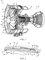
- a gas turbine engine 10 in accordance with the present disclosure is shown in Fig. 1 .
- the gas turbine engine 10 includes an engine core 12, a fan assembly 14, and a fan case 16.
- the fan case 16 is arranged to surround the fan blades 18 of the fan assembly 14 to minimize escape of a fan blade 18 in the event of that a fan blade 18 is thrown off of a fan rotor 20 during the operation of the gas turbine engine 10.
- the fan case 16 includes an annular outer shroud 22 and a fan case liner 24 as shown in Figs. 1-5 .
- the fan case 16 is ring shaped and surrounds a central axis 26 to locate the fan assembly 14 between a front end 28 of the fan case 16 and a rear end 29 of the fan case 16.
- the fan case liner 24 is arranged along an inner radial surface 30 of the annular outer shroud 22 and is configured to reinforce the annular outer shroud 22.
- the fan case liner 24 can circumferentially distribute forces during a blade-off event around the annular outer shroud 22 to prevent escape of the fan blade 18 from the fan case 16.
- the fan case liner 24 includes a plurality of fan case liner panels 32, an adhesive layer 34, and optionally fasteners 36, as shown in Fig. 2 .
- the fan case liner panels 32 are arranged to form a continuous ring along the inner radial surface 30 of the annular outer shroud 22, as shown in Figs. 1 , 3, and 4 .
- the adhesive layer 34 is arranged to extend between and interconnect the fan case liner panel 32 and the inner radial surface 30.
- the fasteners 36 cooperate with the adhesive layer 34 to couple the fan case liner panel 32 to the fan case 16.
- a fan case liner panel 32 may become deficient during the use of the gas turbine engine 10 and require replacement, as shown in Fig. 3 .
- a first fan case liner panel 32 of the fan case liner 24 can be removed without removing other fan case liner panels 32, as shown in Fig. 4 .
- a second fan case liner panel 32 can be installed.
- a method 100 for repairing the fan case liner 24 is shown in Figs. 5 and 6 .
- Individual fan case liner panels 32 can be replaced by following method 100 without damaging the fan case 16, as shown in Figs. 3 and 4 .
- the method 100 of repairing the fan case liner 24 can include the step 110 of applying heat to the portion of the outer radial surface 54 of the fan case 16 that overlies the fan case liner panel 32 that will be removed, as shown in Fig. 5A , the step 120 of removing the first fan case liner panel 32 from the inner radial surface 30 of the fan case 16, as shown in Fig. 5B , and the step 130 of bonding a second fan case liner panel 32 to the inner radial surface 30, as shown in Fig. 5C and 6 .
- the fan case liner panel 32 includes a bonding layer 38, a surface layer 40, and a core layer 42, as shown in Fig. 2 .
- the bonding layer 38 is located between the core layer 42 and the inner radial surface 30 of the fan case 16.
- the surface layer 40 is coupled to the core layer 42 and is arranged to form an outer surface 44 of the fan case liner 24.
- the core layer 42 is arranged to extend between and interconnect the bonding layer 38 and the surface layer 40.
- the surface layer 40 of the fan case liner panel 32 provides the outer surface 44, as shown in Figs. 1 and 2 .
- the surface layer 40 comprises a composite material.
- the surface layer 40 is aramid polymer.
- the core layer 42 is located between the bonding layer 38 and the surface layer 40.
- the core layer 42 comprises a honeycomb material.
- the core layer 42 comprises an aluminum honeycomb material.
- the bonding layer 38 is located between the core layer 42 and the inner radial surface 30 of the fan case 16, as shown in Fig. 2 .
- the bonding layer 38 comprises a glass fiber material.
- the bonding layer 38 comprises a carbon fiber material.
- the fan case liner panel 32 can be coupled to the inner radial surface 30 of the annular outer shroud 22 with an adhesive layer 34.
- the adhesive layer 34 is located between the bonding layer 38 and the inner radial surface 30.
- the adhesive layer 34 comprises a polysulphide adhesive.
- the adhesive layer 34 comprises a polythioether adhesive. While polysulphide and polythioether adhesives are described, it should be understood that adhesive layer 34 may comprise any suitable adhesive.
- the bonding strength of the adhesive can be weakened by heating to a debonding temperature.
- the debonding temperature is chosen so no damage occurs to the neighboring fan case liner panels 32 or to the fan case 16.
- the debonding temperature may be one of the following values: about 100 °C, about 110 °C, about 120 °C, about 130 °C, about 140 °C, about 145 °C, about 150 °C, about 155 °C, about 160 °C, about 165 °C, about 170 °C, about 180 °C, about 190 °C, and about 200 °C.
- the debonding temperature range can be selected from the following ranges, about 100 °C to about 200 °C, about 120 °C to about 200 °C, about 130 °C to about 200 °C, about 130 °C to about 180 °C, about 130 °C to about 170 °C, about 140 °C to about 160 °C, and about 150 °C to about 160 °C.
- the debonding temperature of the adhesive layer 34 is 150 °C.
- the bonding strength of the adhesive can be weakened by heating to a debonding temperature for the duration of a debonding time.
- the debonding time is chosen so no damage occurs to the neighboring fan case liner panels 32 or to the fan case 16.
- the duration of the debonding time can depend on the debonding temperature. Also, the duration of the debonding time can depend on the thickness of fan case 16. For example, if a fan case 16 is relatively thin, the debonding time will be shorter than if fan case 16 is relatively thick.
- the debonding temperature may be one of the following values: about 1 minute, about 2 minutes, about 3 minutes, about 4 minutes, about 5 minutes, about 10 minutes, about 15 minutes, about 20 minutes, about 25 minutes, about 30 minutes, about 35 minutes, about 45 minutes, about 1 hour, about 2 hours and about 3 hours.
- the debonding time of the adhesive may fall within one of many different ranges.
- the debonding time range can be selected from the following ranges, about 1 minute to about 3 hours, about 1 minute to about 2 hours, about 1 minute to about 1 hour, about 5 minutes to about 1 hour, about 5 minutes to about 45 minutes, about 10 minutes to about 45 minutes, and about 15 minutes to about 30 minutes.
- the fan case liner panel 32 can include a forward section 46 having a first thickness and a rearward section 48 having a greater second thickness, as shown in Fig. 2 .
- the forward section 46 and the rearward section 48 have the same thickness so that the fan case liner panel 32 has a uniform thickness.
- the adhesive layer 34 is located between the rearward section 48 and the fan case 16.
- the forward section 46 is formed to include an aperture 45 located between the fan case 16 and the forward section 46 so that no adhesive layer 34 is between the forward section 46 and the inner radial surface 30.
- the fasteners 36 secure the fan case liner panel 32 to the fan case 16, as shown in Fig. 2 .
- the forward section 46 and the rearward section 48 are formed to include apertures 47,49 configured to receive the fasteners 36.
- the fastener 36 is a bolt, however any fastener suitable for securing the fan case liner panel 32 to the fan case 16 can be used, such as a screw or a rivet.
- the fan case liner panel 32 does not include apertures 47,49 and is secured to the fan case 16 only with an adhesive layer.
- a heat source 52 is used for heating the adhesive layer 34 to a debonding temperature, as shown in Fig. 2 .
- the heat source 52 is configured to apply heat to the portion of the fan case 16 containing the fan case liner panel 32 to be removed. It should be understood that heat source 52 can be configured to apply heat to any number of fan track liner panels 32 so that multiple fan case liner panels 32 can be removed simultaneously.
- the heat source 52 is arranged along an outer radial surface 54 of the fan case 16.
- the heat source 52 is a heating element.
- the heat source 52 is a silicon heat mat.
- the heat source 52 is a flexible silicon heat mat.
- the heat source can be a hot air blower or a radiant lamp.
- electricity can be applied to the heat source 52 to produce heat.
- the flexible silicon heating mat can be configured to match the area of the first fan case liner panel 32 requiring removal.
- a method 100 of repairing the fan case liner 24 includes the step 110 of applying heat to a portion of the outer radial surface 54 of the fan case 16, the step 120 of removing the first fan case liner panel 32 from the inner radial surface 30 of the fan case 16, and the step 130 of bonding a second fan case liner panel 32 to the inner radial surface 30, as shown in Figs. 5 and 6 .
- the method 100 further includes the step 140 of removing any edge filler or fastener filler from the fan case liner 24.
- the step 110 of applying heat to a portion of the outer radial surface 54 includes a step 112 of arranging a heat source 52 along a portion of the outer radial surface 54 of the fan case 16 that overlies the fan case liner panel 32 to be removed, as shown in Figs.5A and 6 .
- the step 110 of applying heat to the portion of the outer radial surface 54 can include a step 114 of connecting the heat source 52 to a power source to provide electricity to the heat source 52, as shown in Fig. 6 .
- the heat source 52 is a flexible silicon heating mat and heats the fan case liner panel 32 to the debonding temperature for the debonding time of the adhesive layer 34.
- the step 110 of applying heat to a portion of the outer radial surface 54 can ease the removal of the first fan case liner panel 32 and prevent damage to the inner radial surface 30.
- the annular outer shroud 22 of the fan case 16 comprises a temperature conductive material.
- the annular outer shroud 22 comprises a composite material, or may comprise an alloy.
- the step 120 of removing the first fan case liner panel includes the step 122 of manually removing the debonded, or first, fan case liner panel 32, as shown in Figs. 5B and 6 .
- the step 122 can include prying the first fan case liner panel 32.
- the step 120 of removing the first fan case liner panel can further include the step 124 of cleaning the adhesive residue from the fan case 16.
- the step 120 of removing the first fan case liner panel 32 can further include and the step 126 of cleaning and preparing the edges of the bonded fan case liner panels 32 located on the inner radial surface 30.
- the step 124 of cleaning the adhesive residue is performed with a scraper, or optionally, the step 124 of cleaning the adhesive residue is performed with a solvent. In yet another embodiment, the step 124 of cleaning the adhesive residue is performed with both a scraper and a solvent.
- the step 130 of bonding a second fan case liner panel 32 to the inner radial surface 30 includes the step 132 of cleaning the inner radial surface 30 of the fan case 16 to yield an undisrupted inner surface and applying an unbonded adhesive layer 35, as shown in Figs. 5C and 6 .
- the step 130 of bonding a second fan case liner panel 32 to the inner radial surface 30 can further include the step 134 of securing a second fan case liner panel 32 with the unbonded adhesive layer 35 and the fasteners 36. Once contacted, the unbonded adhesive layer 35 bonds to the fan case liner panel 32 and forms an adhesive layer 34.
- the step 130 of bonding a second fan case liner panel 32 to the inner radial surface 30 can further include the step 136 of activating the heat source 52 to accelerate the cure time of the adhesive layer 34 and produce the repaired fan case liner 24, as shown in Fig. 5D .
- the method 100 of repairing the fan case liner 24 further includes the step 140 of preparing the first fan case liner panel 32 for debonding by removing and separating fastener and edge filler material, as shown in Fig. 6 . After completion of step 140, the fasteners 36 and the fan case liner panel 32 are replaceable during steps 110, 120, and 130.
- method 100 can include each of the steps 110, 120, 130, and 140, or optionally only include a subset of steps 110, 120, 130, and 140 depending on the application. Furthermore, it is understood to one skilled in the art that each of the steps included in each of steps 110, 120, 130, and 140 may be omitted.
- the present disclosure is a process whereby a heating element such as a silicon or similar flexible heating element, temporarily applies heat to the outside of a fan case 16. Heating the exterior of the fan case 16 heats the adhesive layer 34 of the liner by conduction to the point where the adhesive softens enough to remove the fan attrition liner or acoustic panel from the case. This may be accomplished without chiseling. Once the panel is removed, the residual adhesive may be removed with plastic or aluminum scrapers, abrasive pads and acetone, or a heat gun. This process simplifies panel removal while leaving a clean and undamaged fan case 16 surface to which a new liner may be applied. It is appreciated that for a titanium case, the adhesive softening temperature is well below any temperature that may adversely affect the titanium material or any other material of the fan case 16.
- one or more silicon heating mats are applied to the outer radial surface 54 of fan case 16 as shown in Fig. 2 . It is appreciated that mats are located opposite interior surface of fan case 16 and from adhesive layer 34 and fan case liner 24. It is further appreciated that heat transfer, such as conduction through one side of fan case 16 to adhesive layer 34, may be made by any variety of means such as those previously discussed. Illustratively a polysulphide adhesive, a polythioether, or anadhesive film may be used herein. The adhesive may be heated to a temperature of about 150 °C to about 160 °C.
- fan case liner panel 32 With sufficient heat applied, the adhesive characteristics of adhesive layer 34 between fan case liner 24 and fan case 16 are destroyed. This allows the fan case liner panel 32 to be removed exposing inner radial surface 30, as shown in Fig. 5 .
- a pry bar may be used to remove the liner or panel. It is appreciated that less effort is required to pry the liner or panel off since it was heated. With the liner or panel removed, any residual adhesive on fan case 16 where the liner once was may be removed from inner radial surface 30 by a scraper. Once that is complete, fan case 16 may be reconditioned and readied to receive a second fan case liner panel 32, as shown in Fig. 5 . Alternatively, the removal process may be repeated for any additional liners or panels on the case that need replacing.
- This process may be implemented on the front or rear of any fan case 16 where there is access to its exterior opposite the liner or panel to be removed.
- the liner or panel is bonded with an adhesive and the case material is sufficiently conductive to transfer adequate heat to the adhesive, it will soften.
- any meltable or thermoplastic-like bonding panel liner to the fan case may be removed with this method including acoustic panels, fan case liners, and fillers.
- an acoustic panel can be coupled to a surface with an adhesive.
- a method to replace the acoustic panel can comprise arranging a heating element along an exterior portion of an acoustic case that overlies the acoustic panel that needs to be replaced, heating the acoustic case to a debonding temperature, prying the acoustic.
Landscapes
- Engineering & Computer Science (AREA)
- Mechanical Engineering (AREA)
- General Engineering & Computer Science (AREA)
- Manufacturing & Machinery (AREA)
- Structures Of Non-Positive Displacement Pumps (AREA)
Abstract
Description
- This application claims priority to and the benefit of
U.S. Provisional Patent Application Number 62/084,341, filed 25 November 2014 - The present disclosure is related to repairing a fan case liner in a gas turbine engine, and particularly to a method of replacing a fan case liner panel.
- Gas turbine engines used in aircraft often include a fan assembly that is driven by an engine core to push air through the engine and provide thrust for the aircraft. A typical fan assembly includes a fan rotor having blades and a fan case that extends around the blades of the fan rotor. During operation, the fan blades of the fan rotor are rotated to push air through the engine. The fan case both guides the air pushed by the fan blades and provides a protective band that blocks fan blades from being thrown out of the fan assembly in case of a blade-off event in which a fan blade is released from the fan rotor.
- Fan cases may optionally include sound attenuation devices (sometimes called dampers), and composite reinforcements (sometimes called fan case liners or fan track liners). Composite reinforcements, or fan case liners, are generally used to strengthen the fan cases and may be coupled to the metallic shrouds with adhesives.
- The present disclosure may comprise one or more of the following features and combinations thereof.
- According to an aspect of the present disclosure, a method of replacing a fan case liner in a fan case may include applying heat to a portion of an exterior surface of a fan case to soften an adhesive layer bonding a first fan case liner panel to an inner surface of the fan case, removing the first fan case liner panel and adhesive residue from the fan case to produce an undisrupted inner surface of the fan case, and bonding a second fan case liner panel to the undisrupted inner surface of the fan case. The step of applying heat to the portion of the exterior of the fan case is performed on the portion of the fan case containing the first fan case liner panel.
- In some embodiments, applying heat to the portion of the exterior of the fan case includes arranging a heating element along the exterior surface of the fan case and providing electricity to the heating element to heat the adhesive layer to a debonding temperature. In another embodiment, the heating element comprises a flexible silicon heating mat. In another embodiment, the portion of the exterior surface of the fan case overlies the first fan case liner panel. In yet another embodiment, the debonding temperature is about 150 °C to about 160 °C. In some embodiments, the fan case is held at the debonding temperature for about five minutes to about one hour.
- In some embodiments, removing the first fan case liner panel includes prying the first fan case liner panel from the fan case. In another embodiment, removing the adhesive residue includes applying a solvent and manually removing the adhesive residue. Illustratively, manually removing the adhesive residue from the inner surface of the fan case can be performed with a scraper.
- In some embodiments, bonding the second fan case liner panel includes applying an unbonded adhesive layer to the undisrupted inner surface of the fan case and bonding the second fan case liner panel to the unbonded adhesive layer and the undisrupted inner surface. In an embodiment, heating the exterior surface of the fan case can bond the second fan case liner panel to the fan case.
- In some embodiments, a method further includes removing edge and fastener fillers prior to applying heat to the exterior surface of the fan case.
- In some embodiments, the fan case liner panel includes a bonding layer, a surface layer, and a core layer arranged to extend between and interconnect the bonding layer and the surface layer. In an embodiment, the adhesive layer is located between the bonding layer of the fan case liner panel and the inner surface of the fan case. In an embodiment, the adhesive layer comprises a polysulphide adhesive. In an alternative embodiment, the adhesive layer comprises a polythioether adhesive.
- In some embodiments, the fan case includes a plurality of fan case liner panels arranged in a ring along the inner surface of the fan case to circumferentially surround a fan included in a gas turbine engine.
- According to another aspect of the present disclosure, a method of replacing a fan case liner in a fan case may include applying heat to an exterior surface of a fan case to soften an adhesive bonding a first fan case liner panel to an inner surface of the fan case, removing the first fan case liner panel and adhesive residue from the fan case to produce an undisrupted surface of the fan case, and bonding a second fan case liner panel to the undisrupted surface of the fan case. In some embodiments, applying heat to the exterior of the fan case is performed on a portion of the fan case containing the first fan case liner panel, the first fan case liner panel includes a bonding layer, a surface layer, a core layer arranged to extend between and interconnect the bonding layer and the surface layer, and an adhesive layer located between the bonding layer of the first fan case liner panel and the inner surface of the fan case.
- According to another aspect of the present disclosure, a replaceable fan case liner system for a gas turbine engine may include a ring-shaped fan case, a heat source, and a fan case liner system. The ring-shaped fan case can be arranged to surround circumferentially a fan. The heat source can be arranged to extend along the exterior surface of the ring-shaped fan case. The fan case liner system can be configured to extend around an inner surface of the ring-shaped fan case between the fan and the ring-shaped fan case.
- In some embodiments, the fan case liner system includes a fan case liner panel coupled to the ring-shaped fan case that forms a continuous ring on the inner surface of the ring-shaped fan case and the fan case liner panel is configured to bond to the inner surface of the ring-shaped fan case.
- In some embodiments, the fan case liner system further includes an adhesive layer located between the fan case liner panel and the inner surface of the ring-shaped fan case.
- These and other features of the present disclosure will become more apparent from the following description of the illustrative embodiments.
-
-
Fig. 1 is a cutaway view of a gas turbine engine including a fan case showing that the fan case surrounds fan blades included in a fan assembly and showing that the fan case includes an annular outer shroud and a fan case liner formed by a number of segments positioned between the fan blades and the annular outer shroud; -
Fig. 2 is a cross-sectional view of a portion of the fan case showing a fan case liner panel coupled to the fan case; -
Fig. 3 is a perspective view of a fan case showing a first section of the fan case liner; -
Fig. 4 is a perspective view of a fan case showing that a first section of the fan case liner can be removed; -
Fig. 5 is a series of perspective views showing some of the steps for replacing a first fan case liner panel of the fan case liner; -
Fig. 5a shows a first fan case liner panel; -
Fig. 5b shows the removal of a first fan case liner panel; -
Fig. 5c shows a second fan case liner panel positioned to be added to the location vacated by the first section of the fan case liner; -
Fig. 5d shows a repaired fan case liner with the second fan case liner panel in the section where the first fan case liner panel was previously located; and -
Fig. 6 is a diagrammatic chart of a fan case liner panel replacement method in accordance with the present disclosure. - For the purposes of promoting an understanding of the principles of the disclosure, reference will now be made to a number of illustrative embodiments illustrated in the drawings and specific language will be used to describe the same.
- A
gas turbine engine 10 in accordance with the present disclosure is shown inFig. 1 . Thegas turbine engine 10 includes anengine core 12, afan assembly 14, and afan case 16. Thefan case 16 is arranged to surround thefan blades 18 of thefan assembly 14 to minimize escape of afan blade 18 in the event of that afan blade 18 is thrown off of afan rotor 20 during the operation of thegas turbine engine 10. - The
fan case 16 includes an annularouter shroud 22 and afan case liner 24 as shown inFigs. 1-5 . Thefan case 16 is ring shaped and surrounds acentral axis 26 to locate thefan assembly 14 between afront end 28 of thefan case 16 and arear end 29 of thefan case 16. Thefan case liner 24 is arranged along an innerradial surface 30 of the annularouter shroud 22 and is configured to reinforce the annularouter shroud 22. Thefan case liner 24 can circumferentially distribute forces during a blade-off event around the annularouter shroud 22 to prevent escape of thefan blade 18 from thefan case 16. - The
fan case liner 24 includes a plurality of fancase liner panels 32, anadhesive layer 34, and optionallyfasteners 36, as shown inFig. 2 . The fancase liner panels 32 are arranged to form a continuous ring along the innerradial surface 30 of the annularouter shroud 22, as shown inFigs. 1 ,3, and 4 . Theadhesive layer 34 is arranged to extend between and interconnect the fancase liner panel 32 and the innerradial surface 30. Thefasteners 36 cooperate with theadhesive layer 34 to couple the fancase liner panel 32 to thefan case 16. - A fan
case liner panel 32, sometimes called a fan track liner, may become deficient during the use of thegas turbine engine 10 and require replacement, as shown inFig. 3 . Illustratively, a first fancase liner panel 32 of thefan case liner 24 can be removed without removing other fancase liner panels 32, as shown inFig. 4 . After removing the first fancase liner panel 32, a second fancase liner panel 32 can be installed. - A method 100 for repairing the
fan case liner 24 is shown inFigs. 5 and6 . Individual fancase liner panels 32 can be replaced by following method 100 without damaging thefan case 16, as shown inFigs. 3 and 4 . The method 100 of repairing thefan case liner 24 can include thestep 110 of applying heat to the portion of the outerradial surface 54 of thefan case 16 that overlies the fancase liner panel 32 that will be removed, as shown inFig. 5A , thestep 120 of removing the first fancase liner panel 32 from the innerradial surface 30 of thefan case 16, as shown inFig. 5B , and thestep 130 of bonding a second fancase liner panel 32 to the innerradial surface 30, as shown inFig. 5C and6 . - The fan
case liner panel 32 includes abonding layer 38, asurface layer 40, and acore layer 42, as shown inFig. 2 . Thebonding layer 38 is located between thecore layer 42 and the innerradial surface 30 of thefan case 16. Thesurface layer 40 is coupled to thecore layer 42 and is arranged to form anouter surface 44 of thefan case liner 24. Thecore layer 42 is arranged to extend between and interconnect thebonding layer 38 and thesurface layer 40. - Illustratively, the
surface layer 40 of the fancase liner panel 32 provides theouter surface 44, as shown inFigs. 1 and 2 . In an embodiment, thesurface layer 40 comprises a composite material. In another embodiment, thesurface layer 40 is aramid polymer. - The
core layer 42 is located between thebonding layer 38 and thesurface layer 40. In an embodiment, thecore layer 42 comprises a honeycomb material. In another embodiment, thecore layer 42 comprises an aluminum honeycomb material. - The
bonding layer 38 is located between thecore layer 42 and the innerradial surface 30 of thefan case 16, as shown inFig. 2 . In an embodiment, thebonding layer 38 comprises a glass fiber material. In another embodiment, thebonding layer 38 comprises a carbon fiber material. - The fan
case liner panel 32 can be coupled to the innerradial surface 30 of the annularouter shroud 22 with anadhesive layer 34. Theadhesive layer 34 is located between thebonding layer 38 and the innerradial surface 30. In an embodiment, theadhesive layer 34 comprises a polysulphide adhesive. In another embodiment, theadhesive layer 34 comprises a polythioether adhesive. While polysulphide and polythioether adhesives are described, it should be understood thatadhesive layer 34 may comprise any suitable adhesive. - The bonding strength of the adhesive can be weakened by heating to a debonding temperature. The debonding temperature is chosen so no damage occurs to the neighboring fan
case liner panels 32 or to thefan case 16. The debonding temperature may be one of the following values: about 100 °C, about 110 °C, about 120 °C, about 130 °C, about 140 °C, about 145 °C, about 150 °C, about 155 °C, about 160 °C, about 165 °C, about 170 °C, about 180 °C, about 190 °C, and about 200 °C. In an embodiment, the debonding temperature range can be selected from the following ranges, about 100 °C to about 200 °C, about 120 °C to about 200 °C, about 130 °C to about 200 °C, about 130 °C to about 180 °C, about 130 °C to about 170 °C, about 140 °C to about 160 °C, and about 150 °C to about 160 °C. In an embodiment, the debonding temperature of theadhesive layer 34 is 150 °C. - The bonding strength of the adhesive can be weakened by heating to a debonding temperature for the duration of a debonding time. The debonding time is chosen so no damage occurs to the neighboring fan
case liner panels 32 or to thefan case 16. The duration of the debonding time can depend on the debonding temperature. Also, the duration of the debonding time can depend on the thickness offan case 16. For example, if afan case 16 is relatively thin, the debonding time will be shorter than iffan case 16 is relatively thick. The debonding temperature may be one of the following values: about 1 minute, about 2 minutes, about 3 minutes, about 4 minutes, about 5 minutes, about 10 minutes, about 15 minutes, about 20 minutes, about 25 minutes, about 30 minutes, about 35 minutes, about 45 minutes, about 1 hour, about 2 hours and about 3 hours. The debonding time of the adhesive may fall within one of many different ranges. In an embodiment, the debonding time range can be selected from the following ranges, about 1 minute to about 3 hours, about 1 minute to about 2 hours, about 1 minute to about 1 hour, about 5 minutes to about 1 hour, about 5 minutes to about 45 minutes, about 10 minutes to about 45 minutes, and about 15 minutes to about 30 minutes. - The fan
case liner panel 32 can include aforward section 46 having a first thickness and arearward section 48 having a greater second thickness, as shown inFig. 2 . In an embodiment, theforward section 46 and therearward section 48 have the same thickness so that the fancase liner panel 32 has a uniform thickness. Illustratively, theadhesive layer 34 is located between therearward section 48 and thefan case 16. Theforward section 46 is formed to include an aperture 45 located between thefan case 16 and theforward section 46 so that noadhesive layer 34 is between theforward section 46 and the innerradial surface 30. - The
fasteners 36 secure the fancase liner panel 32 to thefan case 16, as shown inFig. 2 . Theforward section 46 and therearward section 48 are formed to includeapertures fasteners 36. Illustratively, thefastener 36 is a bolt, however any fastener suitable for securing the fancase liner panel 32 to thefan case 16 can be used, such as a screw or a rivet. In another embodiment in accordance with the present disclosure, the fancase liner panel 32 does not includeapertures fan case 16 only with an adhesive layer. - A
heat source 52 is used for heating theadhesive layer 34 to a debonding temperature, as shown inFig. 2 . Theheat source 52 is configured to apply heat to the portion of thefan case 16 containing the fancase liner panel 32 to be removed. It should be understood thatheat source 52 can be configured to apply heat to any number of fantrack liner panels 32 so that multiple fancase liner panels 32 can be removed simultaneously. Theheat source 52 is arranged along an outerradial surface 54 of thefan case 16. In an embodiment, theheat source 52 is a heating element. In another embodiment, theheat source 52 is a silicon heat mat. In yet another embodiment, theheat source 52 is a flexible silicon heat mat. Illustratively, in some embodiments the heat source can be a hot air blower or a radiant lamp. In one aspect, electricity can be applied to theheat source 52 to produce heat. The flexible silicon heating mat can be configured to match the area of the first fancase liner panel 32 requiring removal. - A method 100 of repairing the
fan case liner 24 includes thestep 110 of applying heat to a portion of the outerradial surface 54 of thefan case 16, thestep 120 of removing the first fancase liner panel 32 from the innerradial surface 30 of thefan case 16, and thestep 130 of bonding a second fancase liner panel 32 to the innerradial surface 30, as shown inFigs. 5 and6 . In an embodiment, the method 100 further includes thestep 140 of removing any edge filler or fastener filler from thefan case liner 24. - Illustratively, the
step 110 of applying heat to a portion of the outerradial surface 54 includes astep 112 of arranging aheat source 52 along a portion of the outerradial surface 54 of thefan case 16 that overlies the fancase liner panel 32 to be removed, as shown inFigs.5A and6 . Thestep 110 of applying heat to the portion of the outerradial surface 54 can include astep 114 of connecting theheat source 52 to a power source to provide electricity to theheat source 52, as shown inFig. 6 . Illustratively, theheat source 52 is a flexible silicon heating mat and heats the fancase liner panel 32 to the debonding temperature for the debonding time of theadhesive layer 34. Thestep 110 of applying heat to a portion of the outerradial surface 54 can ease the removal of the first fancase liner panel 32 and prevent damage to the innerradial surface 30. - The annular
outer shroud 22 of thefan case 16 comprises a temperature conductive material. In an embodiment, the annularouter shroud 22 comprises a composite material, or may comprise an alloy. During thestep 110 of applying heat to the outerradial surface 54, the heat produced by theheat source 52 is conducted through the annularouter shroud 22 and increases the temperature of theadhesive layer 34 to the debonding temperature. - Illustratively, the
step 120 of removing the first fan case liner panel includes thestep 122 of manually removing the debonded, or first, fancase liner panel 32, as shown inFigs. 5B and6 . Thestep 122 can include prying the first fancase liner panel 32. Thestep 120 of removing the first fan case liner panel can further include thestep 124 of cleaning the adhesive residue from thefan case 16. Thestep 120 of removing the first fancase liner panel 32 can further include and thestep 126 of cleaning and preparing the edges of the bonded fancase liner panels 32 located on the innerradial surface 30. Illustratively, thestep 124 of cleaning the adhesive residue is performed with a scraper, or optionally, thestep 124 of cleaning the adhesive residue is performed with a solvent. In yet another embodiment, thestep 124 of cleaning the adhesive residue is performed with both a scraper and a solvent. - Illustratively, the
step 130 of bonding a second fancase liner panel 32 to the innerradial surface 30 includes thestep 132 of cleaning the innerradial surface 30 of thefan case 16 to yield an undisrupted inner surface and applying anunbonded adhesive layer 35, as shown inFigs. 5C and6 . Thestep 130 of bonding a second fancase liner panel 32 to the innerradial surface 30 can further include thestep 134 of securing a second fancase liner panel 32 with theunbonded adhesive layer 35 and thefasteners 36. Once contacted, theunbonded adhesive layer 35 bonds to the fancase liner panel 32 and forms anadhesive layer 34. Thestep 130 of bonding a second fancase liner panel 32 to the innerradial surface 30 can further include thestep 136 of activating theheat source 52 to accelerate the cure time of theadhesive layer 34 and produce the repairedfan case liner 24, as shown inFig. 5D . - In an embodiment, the method 100 of repairing the
fan case liner 24 further includes thestep 140 of preparing the first fancase liner panel 32 for debonding by removing and separating fastener and edge filler material, as shown inFig. 6 . After completion ofstep 140, thefasteners 36 and the fancase liner panel 32 are replaceable duringsteps - It is understood to one skilled in the art that method 100 can include each of the
steps steps steps - The present disclosure is a process whereby a heating element such as a silicon or similar flexible heating element, temporarily applies heat to the outside of a
fan case 16. Heating the exterior of thefan case 16 heats theadhesive layer 34 of the liner by conduction to the point where the adhesive softens enough to remove the fan attrition liner or acoustic panel from the case. This may be accomplished without chiseling. Once the panel is removed, the residual adhesive may be removed with plastic or aluminum scrapers, abrasive pads and acetone, or a heat gun. This process simplifies panel removal while leaving a clean andundamaged fan case 16 surface to which a new liner may be applied. It is appreciated that for a titanium case, the adhesive softening temperature is well below any temperature that may adversely affect the titanium material or any other material of thefan case 16. - To remove the first fan
case liner panel 32, one or more silicon heating mats are applied to the outerradial surface 54 offan case 16 as shown inFig. 2 . It is appreciated that mats are located opposite interior surface offan case 16 and fromadhesive layer 34 andfan case liner 24. It is further appreciated that heat transfer, such as conduction through one side offan case 16 toadhesive layer 34, may be made by any variety of means such as those previously discussed. Illustratively a polysulphide adhesive, a polythioether, or anadhesive film may be used herein. The adhesive may be heated to a temperature of about 150 °C to about 160 °C. - With sufficient heat applied, the adhesive characteristics of
adhesive layer 34 betweenfan case liner 24 andfan case 16 are destroyed. This allows the fancase liner panel 32 to be removed exposing innerradial surface 30, as shown inFig. 5 . A pry bar may be used to remove the liner or panel. It is appreciated that less effort is required to pry the liner or panel off since it was heated. With the liner or panel removed, any residual adhesive onfan case 16 where the liner once was may be removed from innerradial surface 30 by a scraper. Once that is complete,fan case 16 may be reconditioned and readied to receive a second fancase liner panel 32, as shown inFig. 5 . Alternatively, the removal process may be repeated for any additional liners or panels on the case that need replacing. - This process may be implemented on the front or rear of any
fan case 16 where there is access to its exterior opposite the liner or panel to be removed. Where the liner or panel is bonded with an adhesive and the case material is sufficiently conductive to transfer adequate heat to the adhesive, it will soften. It is contemplated that any meltable or thermoplastic-like bonding panel liner to the fan case may be removed with this method including acoustic panels, fan case liners, and fillers. - In another aspect of the present disclosure, the methods described herein can apply to acoustic panels. Illustratively, an acoustic panel can be coupled to a surface with an adhesive. A method to replace the acoustic panel can comprise arranging a heating element along an exterior portion of an acoustic case that overlies the acoustic panel that needs to be replaced, heating the acoustic case to a debonding temperature, prying the acoustic.
- While the disclosure has been illustrated and described in detail in the foregoing drawings and description, the same is to be considered as exemplary and not restrictive in character, it being understood that only illustrative embodiments thereof have been shown and described and that all changes and modifications that come within the spirit of the disclosure are desired to be protected.
Claims (15)
- A method of replacing a fan case liner in a fan case, the method comprising
applying heat to a portion of an exterior surface of a fan case to soften an adhesive layer bonding a first fan case liner panel to an inner surface of the fan case,
removing the first fan case liner panel and adhesive residue from the fan case to produce an undisrupted inner surface of the fan case, and
bonding a second fan case liner panel to the undisrupted inner surface of the fan case, wherein
applying heat to the portion of the exterior of the fan case is performed on the portion of the fan case containing the first fan case liner panel. - The method of claim 1, wherein applying heat to the portion of the exterior of the fan case includes arranging a heating element along the exterior surface of the fan case and providing electricity to the heating element to heat the adhesive layer to a debonding temperature.
- The method of claim 2, wherein:(i) the heating element comprises a flexible silicon heating mat; and/or(ii) the portion of the exterior surface of the fan case overlies the first fan case liner panel.
- The method of claim 2 or 3, wherein the debonding temperature is about 150 °C to about 160 °C.
- The method of any one of claims 2 to 4, wherein the fan case is held at the debonding temperature for about five minutes to about one hour.
- The method of any preceding claim, wherein:(i) removing the first fan case liner panel includes prying the first fan case liner panel from the fan case; and/or(ii) removing the adhesive residue includes applying a solvent and manually removing the adhesive residue, optionally wherein manually removing the adhesive residue from the inner surface of the fan case is performed with a scraper.
- The method of any preceding claim, wherein bonding the second fan case liner panel includes applying an unbonded adhesive layer to the undisrupted inner surface of the fan case and bonding the second fan case liner panel to the unbonded adhesive layer and the undisrupted inner surface, optionally wherein the method further includes heating the exterior surface of the fan case to bond the second fan case liner panel to the fan case.
- The method of any preceding claim, further including removing edge fillers prior to applying heat to the exterior surface of the fan case.
- The method of any preceding claim, wherein the first fan case liner panel includes a bonding layer, a surface layer, and a core layer arranged to extend between and interconnect the bonding layer and the surface layer.
- The method of claim 9, wherein the adhesive layer is located between the bonding layer of the first fan case liner panel and the inner surface of the fan case.
- The method of claim 10, wherein the adhesive layer comprises a polysulphide adhesive or a polythioether adhesive.
- The method of any preceding claim, wherein the fan case includes a plurality of fan case liner panels arranged in a ring along the inner surface of the fan case to circumferentially surround a fan included in a gas turbine engine.
- A method of replacing a fan case liner in a fan case, the method comprising
applying heat to an exterior surface of a fan case to soften an adhesive bonding a first fan case liner panel to an inner surface of the fan case,
removing the first fan case liner panel and adhesive residue from the fan case to produce an undisrupted surface of the fan case, and
bonding a second fan case liner panel to the undisrupted surface of the fan case,
wherein, applying heat to the exterior of the fan case is performed on a portion of the fan case containing the first fan case liner panel, the first fan case liner panel includes a bonding layer, a surface layer, a core layer arranged to extend between and interconnect the bonding layer and the surface layer, and an adhesive layer located between the bonding layer of the first fan case liner panel and the inner surface of the fan case. - A replaceable fan case liner system for a turbine engine comprising,
a ring-shaped fan case arranged to circumferentially surround a fan,
a heat source arranged to extend along an exterior surface of the ring-shaped fan case, and
a fan case liner system configured to extend around an inner surface of the ring-shaped fan case between the fan and the ring-shaped fan case,
wherein the fan case liner system includes a fan case liner panel coupled to the ring-shaped fan case that forms a continuous ring on the inner surface of the ring-shaped fan case and the fan case liner panel is configured to bond to the inner surface of the ring-shaped fan case. - The fan case liner system of claim 14, wherein the fan case liner system further includes an adhesive layer located between the fan case liner panel and the inner surface of the ring-shaped fan case.
Applications Claiming Priority (1)
| Application Number | Priority Date | Filing Date | Title |
|---|---|---|---|
| US201462084341P | 2014-11-25 | 2014-11-25 |
Publications (2)
| Publication Number | Publication Date |
|---|---|
| EP3025847A1 true EP3025847A1 (en) | 2016-06-01 |
| EP3025847B1 EP3025847B1 (en) | 2019-10-09 |
Family
ID=54703837
Family Applications (1)
| Application Number | Title | Priority Date | Filing Date |
|---|---|---|---|
| EP15195926.9A Active EP3025847B1 (en) | 2014-11-25 | 2015-11-23 | Fan case liner removal with external heat mat |
Country Status (2)
| Country | Link |
|---|---|
| US (1) | US10030540B2 (en) |
| EP (1) | EP3025847B1 (en) |
Cited By (1)
| Publication number | Priority date | Publication date | Assignee | Title |
|---|---|---|---|---|
| DE102019119626A1 (en) * | 2019-07-19 | 2021-01-21 | Ebm-Papst Mulfingen Gmbh & Co. Kg | Housing ring of an axial fan |
Families Citing this family (5)
| Publication number | Priority date | Publication date | Assignee | Title |
|---|---|---|---|---|
| PL421648A1 (en) * | 2017-05-19 | 2018-12-03 | General Electric Company | Removal of a kevlar wrapper from a fan housing |
| US11162425B2 (en) * | 2019-06-11 | 2021-11-02 | Rolls-Royce Corporation | Assembly fixture |
| US11661855B2 (en) * | 2021-10-25 | 2023-05-30 | Raytheon Technologies Corporation | Low density hybrid knife seal |
| US11680524B1 (en) * | 2021-12-16 | 2023-06-20 | Rolls-Royce Corporation | Turbine engine acoustic panel with outer flange case mounting |
| US11753967B2 (en) * | 2021-12-21 | 2023-09-12 | Rolls-Royce Deutschland Ltd & Co Kg | Fan case assembly for a gas turbine engine |
Citations (4)
| Publication number | Priority date | Publication date | Assignee | Title |
|---|---|---|---|---|
| GB2382380A (en) * | 2001-11-24 | 2003-05-28 | Rolls Royce Plc | A removable abradable lining for the casing assembly of a gas turbine engine |
| GB2407343A (en) * | 2003-10-22 | 2005-04-27 | Rolls Royce Plc | Removable liner for a gas turbine engine |
| EP1860283A2 (en) * | 2006-05-24 | 2007-11-28 | Rolls-Royce plc | Fan casing for a gas turbine engine |
| EP2305984A2 (en) * | 2009-09-30 | 2011-04-06 | Rolls-Royce plc | A method of securing a liner panel to the casing of a turbomachine |
Family Cites Families (19)
| Publication number | Priority date | Publication date | Assignee | Title |
|---|---|---|---|---|
| US3996091A (en) * | 1974-09-11 | 1976-12-07 | General Electric Company | Method and apparatus for heat bonding |
| US5030816A (en) | 1989-08-07 | 1991-07-09 | United Technologies Automotive Inc. | Weldable sealant containing electrically conductive fibers |
| US5114100A (en) * | 1989-12-29 | 1992-05-19 | The Boeing Company | Anti-icing system for aircraft |
| US5344280A (en) * | 1993-05-05 | 1994-09-06 | General Electric Company | Impact resistant fan case liner |
| US5662757A (en) * | 1994-10-17 | 1997-09-02 | General Electric Company | Method of removing an abradable shroud assembly for turbomachinery |
| GB9424659D0 (en) | 1994-12-07 | 1995-02-01 | Belron Int Nv | Releasing of bonded screens |
| DE19911779A1 (en) | 1999-03-17 | 2000-09-28 | Daimler Chrysler Ag | Separation of components adhering to one another, enabling e.g. apparently-spontaneous car body disassembly, is achieved by built-in source of ultrasound or laser light which degrades and cleaves adhesive bonds |
| ATE464362T1 (en) | 2003-04-01 | 2010-04-15 | Bonding Ltd De | METHOD AND DEVICE FOR CONNECTING AND SEPARATING ADHESIONS |
| US6835262B1 (en) * | 2003-06-19 | 2004-12-28 | Northrop Grumman Corporation | Positive pressure hot bonder |
| US7507312B2 (en) | 2005-08-23 | 2009-03-24 | The Boeing Company | Using laser shock loads to debond structures |
| US7935205B2 (en) | 2006-06-19 | 2011-05-03 | United Technologies Corporation | Repair of composite sandwich structures |
| US7823374B2 (en) * | 2006-08-31 | 2010-11-02 | General Electric Company | Heat transfer system and method for turbine engine using heat pipes |
| US8021102B2 (en) * | 2006-11-30 | 2011-09-20 | General Electric Company | Composite fan containment case and methods of fabricating the same |
| US7980813B2 (en) | 2007-08-13 | 2011-07-19 | United Technologies Corporation | Fan outlet guide vane shroud insert repair |
| GB2478144A (en) * | 2010-02-26 | 2011-08-31 | Rolls Royce Plc | Panelled assembly, eg for a gas turbine engine ducted fan casing |
| RS53581B1 (en) | 2010-05-31 | 2015-02-27 | Craig Rookstool | COMPRESSOR HOUSING COAT |
| DE102010051842A1 (en) | 2010-11-18 | 2012-05-24 | Rolls-Royce Deutschland Ltd & Co Kg | Repair method of a sandwich-type component |
| US9309781B2 (en) * | 2011-01-31 | 2016-04-12 | General Electric Company | Heated booster splitter plenum |
| FR2977827B1 (en) * | 2011-07-13 | 2015-03-13 | Snecma | PROCESS FOR MANUFACTURING A TURBOMACHINE BLOWER HOUSING WITH ABRADABLE AND ACOUSTIC COATINGS |
-
2015
- 2015-11-23 US US14/949,247 patent/US10030540B2/en active Active
- 2015-11-23 EP EP15195926.9A patent/EP3025847B1/en active Active
Patent Citations (4)
| Publication number | Priority date | Publication date | Assignee | Title |
|---|---|---|---|---|
| GB2382380A (en) * | 2001-11-24 | 2003-05-28 | Rolls Royce Plc | A removable abradable lining for the casing assembly of a gas turbine engine |
| GB2407343A (en) * | 2003-10-22 | 2005-04-27 | Rolls Royce Plc | Removable liner for a gas turbine engine |
| EP1860283A2 (en) * | 2006-05-24 | 2007-11-28 | Rolls-Royce plc | Fan casing for a gas turbine engine |
| EP2305984A2 (en) * | 2009-09-30 | 2011-04-06 | Rolls-Royce plc | A method of securing a liner panel to the casing of a turbomachine |
Cited By (1)
| Publication number | Priority date | Publication date | Assignee | Title |
|---|---|---|---|---|
| DE102019119626A1 (en) * | 2019-07-19 | 2021-01-21 | Ebm-Papst Mulfingen Gmbh & Co. Kg | Housing ring of an axial fan |
Also Published As
| Publication number | Publication date |
|---|---|
| US10030540B2 (en) | 2018-07-24 |
| US20160146050A1 (en) | 2016-05-26 |
| EP3025847B1 (en) | 2019-10-09 |
Similar Documents
| Publication | Publication Date | Title |
|---|---|---|
| EP3025847B1 (en) | Fan case liner removal with external heat mat | |
| EP2952695B1 (en) | Fan case | |
| US6773535B1 (en) | Article and method for controlled debonding of elements using shape memory alloy actuators | |
| EP1775445B1 (en) | Method of repair for inlet caps of turbine engines | |
| US10731507B2 (en) | Fan case assemblies | |
| US20170198714A1 (en) | Ceramic tile fan blade containment | |
| CN104110276B (en) | Repair procedures and the component repaired | |
| EP2305984B1 (en) | A method of securing a liner panel to the casing of a turbomachine | |
| EP1882725B1 (en) | Removable adhesive for replaceable components subjected to impact loads | |
| EP1930159B1 (en) | A method of applying a constrained layer damping material | |
| CN103328771A (en) | Method for disconnecting, by induction, a magnetic mechanical part adhered to a mechanical part | |
| US20150107108A1 (en) | Method and apparatus for supporting blades | |
| US11215058B2 (en) | Propeller blades | |
| US10717261B2 (en) | Selectively activated frangible bonding system | |
| EP3202954B1 (en) | Repairing a coating with a pre-configured coating patch | |
| US9802380B2 (en) | Method of sticking together and un-sticking two parts by means of a filled adhesive | |
| EP4159361B1 (en) | Method of metal work repair in hybrid composite blades | |
| CN110023065B (en) | Acoustic panel restoration with preserved acoustic properties | |
| US8800149B2 (en) | Process for repairing airplane panels | |
| EP4607006A1 (en) | System and method for assembling a fan case of a gas turbine engine |
Legal Events
| Date | Code | Title | Description |
|---|---|---|---|
| PUAI | Public reference made under article 153(3) epc to a published international application that has entered the european phase |
Free format text: ORIGINAL CODE: 0009012 |
|
| AK | Designated contracting states |
Kind code of ref document: A1 Designated state(s): AL AT BE BG CH CY CZ DE DK EE ES FI FR GB GR HR HU IE IS IT LI LT LU LV MC MK MT NL NO PL PT RO RS SE SI SK SM TR |
|
| AX | Request for extension of the european patent |
Extension state: BA ME |
|
| STAA | Information on the status of an ep patent application or granted ep patent |
Free format text: STATUS: REQUEST FOR EXAMINATION WAS MADE |
|
| 17P | Request for examination filed |
Effective date: 20161125 |
|
| RBV | Designated contracting states (corrected) |
Designated state(s): AL AT BE BG CH CY CZ DE DK EE ES FI FR GB GR HR HU IE IS IT LI LT LU LV MC MK MT NL NO PL PT RO RS SE SI SK SM TR |
|
| GRAP | Despatch of communication of intention to grant a patent |
Free format text: ORIGINAL CODE: EPIDOSNIGR1 |
|
| STAA | Information on the status of an ep patent application or granted ep patent |
Free format text: STATUS: GRANT OF PATENT IS INTENDED |
|
| RIC1 | Information provided on ipc code assigned before grant |
Ipc: F04D 29/52 20060101ALN20190502BHEP Ipc: B29C 63/00 20060101AFI20190502BHEP |
|
| INTG | Intention to grant announced |
Effective date: 20190524 |
|
| RIC1 | Information provided on ipc code assigned before grant |
Ipc: F04D 29/52 20060101ALN20190513BHEP Ipc: B29C 63/00 20060101AFI20190513BHEP |
|
| GRAS | Grant fee paid |
Free format text: ORIGINAL CODE: EPIDOSNIGR3 |
|
| GRAA | (expected) grant |
Free format text: ORIGINAL CODE: 0009210 |
|
| STAA | Information on the status of an ep patent application or granted ep patent |
Free format text: STATUS: THE PATENT HAS BEEN GRANTED |
|
| AK | Designated contracting states |
Kind code of ref document: B1 Designated state(s): AL AT BE BG CH CY CZ DE DK EE ES FI FR GB GR HR HU IE IS IT LI LT LU LV MC MK MT NL NO PL PT RO RS SE SI SK SM TR |
|
| REG | Reference to a national code |
Ref country code: GB Ref legal event code: FG4D |
|
| REG | Reference to a national code |
Ref country code: CH Ref legal event code: EP |
|
| REG | Reference to a national code |
Ref country code: IE Ref legal event code: FG4D |
|
| REG | Reference to a national code |
Ref country code: DE Ref legal event code: R096 Ref document number: 602015039382 Country of ref document: DE |
|
| REG | Reference to a national code |
Ref country code: AT Ref legal event code: REF Ref document number: 1188287 Country of ref document: AT Kind code of ref document: T Effective date: 20191115 |
|
| REG | Reference to a national code |
Ref country code: NL Ref legal event code: MP Effective date: 20191009 |
|
| REG | Reference to a national code |
Ref country code: LT Ref legal event code: MG4D |
|
| RAP2 | Party data changed (patent owner data changed or rights of a patent transferred) |
Owner name: ROLLS-ROYCE NORTH AMERICAN TECHNOLOGIES, INC. Owner name: ROLLS-ROYCE CORPORATION Owner name: ROLLS-ROYCE PLC |
|
| REG | Reference to a national code |
Ref country code: AT Ref legal event code: MK05 Ref document number: 1188287 Country of ref document: AT Kind code of ref document: T Effective date: 20191009 |
|
| PG25 | Lapsed in a contracting state [announced via postgrant information from national office to epo] |
Ref country code: BG Free format text: LAPSE BECAUSE OF FAILURE TO SUBMIT A TRANSLATION OF THE DESCRIPTION OR TO PAY THE FEE WITHIN THE PRESCRIBED TIME-LIMIT Effective date: 20200109 Ref country code: NO Free format text: LAPSE BECAUSE OF FAILURE TO SUBMIT A TRANSLATION OF THE DESCRIPTION OR TO PAY THE FEE WITHIN THE PRESCRIBED TIME-LIMIT Effective date: 20200109 Ref country code: GR Free format text: LAPSE BECAUSE OF FAILURE TO SUBMIT A TRANSLATION OF THE DESCRIPTION OR TO PAY THE FEE WITHIN THE PRESCRIBED TIME-LIMIT Effective date: 20200110 Ref country code: SE Free format text: LAPSE BECAUSE OF FAILURE TO SUBMIT A TRANSLATION OF THE DESCRIPTION OR TO PAY THE FEE WITHIN THE PRESCRIBED TIME-LIMIT Effective date: 20191009 Ref country code: FI Free format text: LAPSE BECAUSE OF FAILURE TO SUBMIT A TRANSLATION OF THE DESCRIPTION OR TO PAY THE FEE WITHIN THE PRESCRIBED TIME-LIMIT Effective date: 20191009 Ref country code: PT Free format text: LAPSE BECAUSE OF FAILURE TO SUBMIT A TRANSLATION OF THE DESCRIPTION OR TO PAY THE FEE WITHIN THE PRESCRIBED TIME-LIMIT Effective date: 20200210 Ref country code: LV Free format text: LAPSE BECAUSE OF FAILURE TO SUBMIT A TRANSLATION OF THE DESCRIPTION OR TO PAY THE FEE WITHIN THE PRESCRIBED TIME-LIMIT Effective date: 20191009 Ref country code: AT Free format text: LAPSE BECAUSE OF FAILURE TO SUBMIT A TRANSLATION OF THE DESCRIPTION OR TO PAY THE FEE WITHIN THE PRESCRIBED TIME-LIMIT Effective date: 20191009 Ref country code: NL Free format text: LAPSE BECAUSE OF FAILURE TO SUBMIT A TRANSLATION OF THE DESCRIPTION OR TO PAY THE FEE WITHIN THE PRESCRIBED TIME-LIMIT Effective date: 20191009 Ref country code: PL Free format text: LAPSE BECAUSE OF FAILURE TO SUBMIT A TRANSLATION OF THE DESCRIPTION OR TO PAY THE FEE WITHIN THE PRESCRIBED TIME-LIMIT Effective date: 20191009 Ref country code: ES Free format text: LAPSE BECAUSE OF FAILURE TO SUBMIT A TRANSLATION OF THE DESCRIPTION OR TO PAY THE FEE WITHIN THE PRESCRIBED TIME-LIMIT Effective date: 20191009 Ref country code: LT Free format text: LAPSE BECAUSE OF FAILURE TO SUBMIT A TRANSLATION OF THE DESCRIPTION OR TO PAY THE FEE WITHIN THE PRESCRIBED TIME-LIMIT Effective date: 20191009 |
|
| PG25 | Lapsed in a contracting state [announced via postgrant information from national office to epo] |
Ref country code: IS Free format text: LAPSE BECAUSE OF FAILURE TO SUBMIT A TRANSLATION OF THE DESCRIPTION OR TO PAY THE FEE WITHIN THE PRESCRIBED TIME-LIMIT Effective date: 20200224 Ref country code: HR Free format text: LAPSE BECAUSE OF FAILURE TO SUBMIT A TRANSLATION OF THE DESCRIPTION OR TO PAY THE FEE WITHIN THE PRESCRIBED TIME-LIMIT Effective date: 20191009 Ref country code: RS Free format text: LAPSE BECAUSE OF FAILURE TO SUBMIT A TRANSLATION OF THE DESCRIPTION OR TO PAY THE FEE WITHIN THE PRESCRIBED TIME-LIMIT Effective date: 20191009 |
|
| PG25 | Lapsed in a contracting state [announced via postgrant information from national office to epo] |
Ref country code: AL Free format text: LAPSE BECAUSE OF FAILURE TO SUBMIT A TRANSLATION OF THE DESCRIPTION OR TO PAY THE FEE WITHIN THE PRESCRIBED TIME-LIMIT Effective date: 20191009 |
|
| REG | Reference to a national code |
Ref country code: CH Ref legal event code: PL |
|
| REG | Reference to a national code |
Ref country code: DE Ref legal event code: R097 Ref document number: 602015039382 Country of ref document: DE |
|
| PG2D | Information on lapse in contracting state deleted |
Ref country code: IS |
|
| PG25 | Lapsed in a contracting state [announced via postgrant information from national office to epo] |
Ref country code: LU Free format text: LAPSE BECAUSE OF NON-PAYMENT OF DUE FEES Effective date: 20191123 Ref country code: DK Free format text: LAPSE BECAUSE OF FAILURE TO SUBMIT A TRANSLATION OF THE DESCRIPTION OR TO PAY THE FEE WITHIN THE PRESCRIBED TIME-LIMIT Effective date: 20191009 Ref country code: EE Free format text: LAPSE BECAUSE OF FAILURE TO SUBMIT A TRANSLATION OF THE DESCRIPTION OR TO PAY THE FEE WITHIN THE PRESCRIBED TIME-LIMIT Effective date: 20191009 Ref country code: CZ Free format text: LAPSE BECAUSE OF FAILURE TO SUBMIT A TRANSLATION OF THE DESCRIPTION OR TO PAY THE FEE WITHIN THE PRESCRIBED TIME-LIMIT Effective date: 20191009 Ref country code: RO Free format text: LAPSE BECAUSE OF FAILURE TO SUBMIT A TRANSLATION OF THE DESCRIPTION OR TO PAY THE FEE WITHIN THE PRESCRIBED TIME-LIMIT Effective date: 20191009 Ref country code: CH Free format text: LAPSE BECAUSE OF NON-PAYMENT OF DUE FEES Effective date: 20191130 Ref country code: LI Free format text: LAPSE BECAUSE OF NON-PAYMENT OF DUE FEES Effective date: 20191130 Ref country code: MC Free format text: LAPSE BECAUSE OF FAILURE TO SUBMIT A TRANSLATION OF THE DESCRIPTION OR TO PAY THE FEE WITHIN THE PRESCRIBED TIME-LIMIT Effective date: 20191009 Ref country code: IS Free format text: LAPSE BECAUSE OF FAILURE TO SUBMIT A TRANSLATION OF THE DESCRIPTION OR TO PAY THE FEE WITHIN THE PRESCRIBED TIME-LIMIT Effective date: 20200209 |
|
| PLBE | No opposition filed within time limit |
Free format text: ORIGINAL CODE: 0009261 |
|
| STAA | Information on the status of an ep patent application or granted ep patent |
Free format text: STATUS: NO OPPOSITION FILED WITHIN TIME LIMIT |
|
| REG | Reference to a national code |
Ref country code: BE Ref legal event code: MM Effective date: 20191130 |
|
| PG25 | Lapsed in a contracting state [announced via postgrant information from national office to epo] |
Ref country code: SM Free format text: LAPSE BECAUSE OF FAILURE TO SUBMIT A TRANSLATION OF THE DESCRIPTION OR TO PAY THE FEE WITHIN THE PRESCRIBED TIME-LIMIT Effective date: 20191009 Ref country code: IT Free format text: LAPSE BECAUSE OF FAILURE TO SUBMIT A TRANSLATION OF THE DESCRIPTION OR TO PAY THE FEE WITHIN THE PRESCRIBED TIME-LIMIT Effective date: 20191009 Ref country code: SK Free format text: LAPSE BECAUSE OF FAILURE TO SUBMIT A TRANSLATION OF THE DESCRIPTION OR TO PAY THE FEE WITHIN THE PRESCRIBED TIME-LIMIT Effective date: 20191009 |
|
| 26N | No opposition filed |
Effective date: 20200710 |
|
| GBPC | Gb: european patent ceased through non-payment of renewal fee |
Effective date: 20200109 |
|
| PG25 | Lapsed in a contracting state [announced via postgrant information from national office to epo] |
Ref country code: IE Free format text: LAPSE BECAUSE OF NON-PAYMENT OF DUE FEES Effective date: 20191123 Ref country code: GB Free format text: LAPSE BECAUSE OF NON-PAYMENT OF DUE FEES Effective date: 20200109 |
|
| PG25 | Lapsed in a contracting state [announced via postgrant information from national office to epo] |
Ref country code: BE Free format text: LAPSE BECAUSE OF NON-PAYMENT OF DUE FEES Effective date: 20191130 Ref country code: SI Free format text: LAPSE BECAUSE OF FAILURE TO SUBMIT A TRANSLATION OF THE DESCRIPTION OR TO PAY THE FEE WITHIN THE PRESCRIBED TIME-LIMIT Effective date: 20191009 |
|
| PG25 | Lapsed in a contracting state [announced via postgrant information from national office to epo] |
Ref country code: CY Free format text: LAPSE BECAUSE OF FAILURE TO SUBMIT A TRANSLATION OF THE DESCRIPTION OR TO PAY THE FEE WITHIN THE PRESCRIBED TIME-LIMIT Effective date: 20191009 |
|
| PG25 | Lapsed in a contracting state [announced via postgrant information from national office to epo] |
Ref country code: HU Free format text: LAPSE BECAUSE OF FAILURE TO SUBMIT A TRANSLATION OF THE DESCRIPTION OR TO PAY THE FEE WITHIN THE PRESCRIBED TIME-LIMIT; INVALID AB INITIO Effective date: 20151123 Ref country code: MT Free format text: LAPSE BECAUSE OF FAILURE TO SUBMIT A TRANSLATION OF THE DESCRIPTION OR TO PAY THE FEE WITHIN THE PRESCRIBED TIME-LIMIT Effective date: 20191009 |
|
| PG25 | Lapsed in a contracting state [announced via postgrant information from national office to epo] |
Ref country code: TR Free format text: LAPSE BECAUSE OF FAILURE TO SUBMIT A TRANSLATION OF THE DESCRIPTION OR TO PAY THE FEE WITHIN THE PRESCRIBED TIME-LIMIT Effective date: 20191009 |
|
| PG25 | Lapsed in a contracting state [announced via postgrant information from national office to epo] |
Ref country code: MK Free format text: LAPSE BECAUSE OF FAILURE TO SUBMIT A TRANSLATION OF THE DESCRIPTION OR TO PAY THE FEE WITHIN THE PRESCRIBED TIME-LIMIT Effective date: 20191009 |
|
| P01 | Opt-out of the competence of the unified patent court (upc) registered |
Effective date: 20230528 |
|
| PGFP | Annual fee paid to national office [announced via postgrant information from national office to epo] |
Ref country code: DE Payment date: 20251126 Year of fee payment: 11 |
|
| PGFP | Annual fee paid to national office [announced via postgrant information from national office to epo] |
Ref country code: FR Payment date: 20251124 Year of fee payment: 11 |