EP1860283A2 - Fan casing for a gas turbine engine - Google Patents
Fan casing for a gas turbine engine Download PDFInfo
- Publication number
- EP1860283A2 EP1860283A2 EP07251769A EP07251769A EP1860283A2 EP 1860283 A2 EP1860283 A2 EP 1860283A2 EP 07251769 A EP07251769 A EP 07251769A EP 07251769 A EP07251769 A EP 07251769A EP 1860283 A2 EP1860283 A2 EP 1860283A2
- Authority
- EP
- European Patent Office
- Prior art keywords
- casing
- liner
- fan
- annulus
- secured
- Prior art date
- Legal status (The legal status is an assumption and is not a legal conclusion. Google has not performed a legal analysis and makes no representation as to the accuracy of the status listed.)
- Withdrawn
Links
Images


Classifications
-
- F—MECHANICAL ENGINEERING; LIGHTING; HEATING; WEAPONS; BLASTING
- F01—MACHINES OR ENGINES IN GENERAL; ENGINE PLANTS IN GENERAL; STEAM ENGINES
- F01D—NON-POSITIVE DISPLACEMENT MACHINES OR ENGINES, e.g. STEAM TURBINES
- F01D21/00—Shutting-down of machines or engines, e.g. in emergency; Regulating, controlling, or safety means not otherwise provided for
- F01D21/04—Shutting-down of machines or engines, e.g. in emergency; Regulating, controlling, or safety means not otherwise provided for responsive to undesired position of rotor relative to stator or to breaking-off of a part of the rotor, e.g. indicating such position
- F01D21/045—Shutting-down of machines or engines, e.g. in emergency; Regulating, controlling, or safety means not otherwise provided for responsive to undesired position of rotor relative to stator or to breaking-off of a part of the rotor, e.g. indicating such position special arrangements in stators or in rotors dealing with breaking-off of part of rotor
-
- F—MECHANICAL ENGINEERING; LIGHTING; HEATING; WEAPONS; BLASTING
- F02—COMBUSTION ENGINES; HOT-GAS OR COMBUSTION-PRODUCT ENGINE PLANTS
- F02C—GAS-TURBINE PLANTS; AIR INTAKES FOR JET-PROPULSION PLANTS; CONTROLLING FUEL SUPPLY IN AIR-BREATHING JET-PROPULSION PLANTS
- F02C7/00—Features, components parts, details or accessories, not provided for in, or of interest apart form groups F02C1/00 - F02C6/00; Air intakes for jet-propulsion plants
- F02C7/04—Air intakes for gas-turbine plants or jet-propulsion plants
- F02C7/05—Air intakes for gas-turbine plants or jet-propulsion plants having provisions for obviating the penetration of damaging objects or particles
-
- F—MECHANICAL ENGINEERING; LIGHTING; HEATING; WEAPONS; BLASTING
- F02—COMBUSTION ENGINES; HOT-GAS OR COMBUSTION-PRODUCT ENGINE PLANTS
- F02K—JET-PROPULSION PLANTS
- F02K3/00—Plants including a gas turbine driving a compressor or a ducted fan
- F02K3/02—Plants including a gas turbine driving a compressor or a ducted fan in which part of the working fluid by-passes the turbine and combustion chamber
- F02K3/04—Plants including a gas turbine driving a compressor or a ducted fan in which part of the working fluid by-passes the turbine and combustion chamber the plant including ducted fans, i.e. fans with high volume, low pressure outputs, for augmenting the jet thrust, e.g. of double-flow type
- F02K3/06—Plants including a gas turbine driving a compressor or a ducted fan in which part of the working fluid by-passes the turbine and combustion chamber the plant including ducted fans, i.e. fans with high volume, low pressure outputs, for augmenting the jet thrust, e.g. of double-flow type with front fan
-
- F—MECHANICAL ENGINEERING; LIGHTING; HEATING; WEAPONS; BLASTING
- F05—INDEXING SCHEMES RELATING TO ENGINES OR PUMPS IN VARIOUS SUBCLASSES OF CLASSES F01-F04
- F05D—INDEXING SCHEME FOR ASPECTS RELATING TO NON-POSITIVE-DISPLACEMENT MACHINES OR ENGINES, GAS-TURBINES OR JET-PROPULSION PLANTS
- F05D2240/00—Components
- F05D2240/90—Mounting on supporting structures or systems
-
- F—MECHANICAL ENGINEERING; LIGHTING; HEATING; WEAPONS; BLASTING
- F05—INDEXING SCHEMES RELATING TO ENGINES OR PUMPS IN VARIOUS SUBCLASSES OF CLASSES F01-F04
- F05D—INDEXING SCHEME FOR ASPECTS RELATING TO NON-POSITIVE-DISPLACEMENT MACHINES OR ENGINES, GAS-TURBINES OR JET-PROPULSION PLANTS
- F05D2260/00—Function
- F05D2260/30—Retaining components in desired mutual position
-
- Y—GENERAL TAGGING OF NEW TECHNOLOGICAL DEVELOPMENTS; GENERAL TAGGING OF CROSS-SECTIONAL TECHNOLOGIES SPANNING OVER SEVERAL SECTIONS OF THE IPC; TECHNICAL SUBJECTS COVERED BY FORMER USPC CROSS-REFERENCE ART COLLECTIONS [XRACs] AND DIGESTS
- Y02—TECHNOLOGIES OR APPLICATIONS FOR MITIGATION OR ADAPTATION AGAINST CLIMATE CHANGE
- Y02T—CLIMATE CHANGE MITIGATION TECHNOLOGIES RELATED TO TRANSPORTATION
- Y02T50/00—Aeronautics or air transport
- Y02T50/60—Efficient propulsion technologies, e.g. for aircraft
Definitions
- This invention relates to gas turbine engines, and more particularly to fan casings for such engines.
- Turbofan gas turbine engines for powering aircraft conventionally comprise a core engine, which drives a fan.
- the fan comprises a number of radially extending fan blades mounted on a fan rotor, enclosed by a generally cylindrical or frustoconical fan casing.
- the core engine comprises one or more turbines, each one of which comprises a number of radially extending turbine blades, enclosed by a generally cylindrical or frustoconical casing.
- containment rings for turbofan gas turbine engine casings is well known. It is known to provide generally cylindrical or frustoconical, relatively thick, metallic containment rings. It is also known to provide generally cylindrical or frustoconical, locally thickened, isogrid metallic containment rings. Furthermore, it is known to provide strong fibrous material wound around relatively thin metallic casings or around the above-mentioned containment casings. In the event that a blade becomes detached it passes through the casing and is contained by the fibrous material.
- fan track liner there is a requirement to provide a fan track liner within the fan casing.
- the fan track liner is attached within the fan casing by mechanical fasteners passing through the liner and secured into or through the fan casing, or by adhesive.
- Adhesive bonding of the fan track liner to the fan casing must be performed under controlled conditions. If a liner has to be replaced in service it may be difficult to control the bonding conditions, and this can result in unsatisfactory attachment of the liner to the casing. It can be difficult to remove a damaged liner without also damaging the fan casing.
- the design of fan casings has to include an allowance for possible weakening caused by such damage. This increases the cost and weight of the fan casing.
- this invention seeks to provide a novel fan track liner for a gas turbine engine which overcomes the above-mentioned problems.
- FIG 1 shows a partial section through a fan case assembly of known type in a gas turbine engine.
- the annular fan case 112 is generally cylindrical or frustoconical in shape. It has a forward flange 15 and a rearward flange 17, attached to further structure of the gas turbine engine, which is not shown. These flanges 15 and 17, and the annulus of the fan case 112 between them, provide a load path through which mechanical loads may be transmitted during the operation of the gas turbine engine.
- Within the annular fan case 112 are secured front acoustic panels 14, rear acoustic panels 16 and fan track liner panels 18. The panels are formed in segments, so that a number of panels are butted together to form a complete ring around the inner surface of the fan case 112. All of the panels are attached to the fan case 112 using adhesive.
- FIG 2 shows the forward part of a fan case arrangement according to the invention.
- the front and rear acoustic panels are omitted for clarity.
- the fan case 212 has two ribs 22 and 24 which extend around the circumference.
- the forward rib 22 is enlarged, at its radially-inner end, to form a foot 26 extending axially forward and rearward.
- the fan track liner 28 comprises an injection moulded liner tray 30.
- the liner tray 30 has an extension 40. Bonded within this tray 30 is a honeycomb panel 32, and attrition liners 34 are in turn bonded to the honeycomb panel 32.
- the liner tray 30 extends around 20° of the circumference, so that a full set of fan track liner panels 28 consists of eighteen panels.
- Each liner panel 28 is secured to the fan case 212 at two axial positions, indicated by the lines 36 and 38. These areas are shown in more detail in Figures 3 and 4.
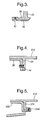
- FIG. 3 shows the extended foot 26 of the forward rib 22.
- the liner tray extension 40 is secured to the foot 26 by a countersunk screw 42.
- each liner panel 28 has three screws 42 spaced circumferentially.
- FIG 4 shows the rearward rib 24 of the fan case 212.
- the rear part of the liner tray 30 is secured to the rib 24 by a countersunk screw 44.
- each liner panel 28 has three screws 44 spaced circumferentially.
- a layer of polysulphide sealant is applied to the outer surface of the liner tray 30. This prevents frettage between the liner tray and the fan casing 212 and damps vibration, and will also help to prevent rotation of the liner panels around the casing 212, in case of heavy rubbing of the fan blade tips on the attrition liner 34.
- Figure 5 shows an alternative arrangement of the rearward rib 24.
- the rib 524 is L-shaped, and so is the rearward part of the liner tray 530.
- the countersunk screw 544 secures the liner tray 530 to the rib 524.
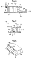
- FIG 6 shows an alternative embodiment of the fan casing arrangement, in which the front acoustic panel (FAP) is incorporated into the fan track liner panel.
- the forward rib 22 can be seen, as in Figure 2, with a foot 626.
- the liner tray 630 is extended forward, to form a second tray 46.
- the front acoustic panel honeycomb 54 is bonded into the second tray 46.
- a hook 48 is formed at the forward extremity of the tray 46.
- the liner panel 628 therefore incorporates both the FAP and the fan track liner.
- a clip 50 secures the hook 48, and thereby the liner panel 628, to the fan casing 612.
- An O-ring seal 52 provides better location of the hook 48 and prevents vibration.
- the rearward end of the liner tray 630 is secured by screws, as in previous embodiments.
- FIG. 7 illustrates such an embodiment.
- the fan casing 212 and the forward rib 22 are as in Figure 2.
- the foot 726 has a groove 56 on its rearward part, to accommodate an O-ring seal 58.
- the liner tray 730 has a part-annular hook 60 formed at its forward end, and this engages with the O-ring seal 58 to provide a radial location of the liner panel 28 within the fan casing 212.
- a number of anti-rotation features 62 are provided within the fan casing 212. These features 62 take the form of pegs, extending radially inwardly from the casing 212 and equally spaced around its circumference.
- each anti-rotation feature 62 locates between respective sides 64a, 64b of a recess 64, so as to prevent the liner panel 28 from moving in a circumferential direction, for example during heavy fan blade rubs.
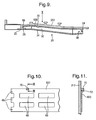
- Figure 9 shows another embodiment of the arrangement of Figure 2, with a further alternative attachment for the forward part of the liner panel.
- the arrangement of the fan casing 212 is substantially as in Figure 2, with forward and rearward ribs 22, 24.
- the forward rib has an enlarged foot 26.
- the liner tray 930 is formed of pressed metal.
- a honeycomb panel 32 is bonded within the liner tray 930, and an attrition liner 34 is bonded to the honeycomb panel 32.
- the forward part of the liner tray 930 is castellated to form hooks 66, which locate inside the foot 26 of the forward rib 22 to provide a radial location.
- Figure 10 is a view along the arrow X in Figure 9.
- each liner tray 930 has three hooks 66.
- the rearward part of the liner tray 930 is fastened in the same manner as in Figure 2.
- Also visible in Figure 10 are four cutouts 68, which reduce the weight of the liner tray 930.
- anti-rotation features 70 are also provided within the fan casing 212. These consist of pegs extending radially inwardly from the casing 212 and equally spaced around its circumference. At an appropriate position on each liner tray 930, a tang 72 is formed by bending a portion of the edge of the liner tray 930. In use, the tang engages with a corresponding peg 70 to prevent rotation of the liner tray.
- Figure 12 shows an alternative mounting arrangement for the forward end of the liner panel 28, in the embodiment of Figure 9.
- Hooks 66 provide a radial location for the liner panel, as described above.
- the anti-rotation features in this arrangement take the form of interlocking castellations. These are more clearly visible in Figure 13, which is a view on the arrow XIII in Figure 12.
- Castellations are formed on the rearward part 74 of the enlarged foot 1226, and on the forward part 76 of the liner tray 930. In use, castellations 78 on the liner tray 930 engage with corresponding castellations 80 on the foot 1226, preventing rotation of the liner panel 28.
- the liner tray 30 may be pressed metal, or composite, or laser cut from metal sheet.
- the liner tray 30 may extend around any convenient arc of the circumference, so that a full set of fan track liner panels 28 consists of fewer or more panels than are described in the embodiments above. It is envisaged that the minimum arc for each panel 28 would be of the order of 10° (a full set consisting of 36 panels), and the maximum arc would be of the order of 90° (a full set consisting of four panels).
- each panel 28 may be any suitable number.
- the O-ring seal 52, 58 may be replaced by a seal of another type, or may be dispensed with altogether.
- the polysulphide sealant may be replaced by an equivalent sealant of different chemical composition.
- the locating recesses 64 may be machined or moulded, according to the material from which the liner tray 730 is made, and may be of a different shape from that shown in Figure 8.
- cutouts 68 may be provided, and they may be of a different shape from that described. Cutouts may also be provided in the liner trays of the other embodiments described. Likewise, the different types of anti-rotation features described in the several embodiments may be freely interchanged between those embodiments.
Abstract


Description
- This invention relates to gas turbine engines, and more particularly to fan casings for such engines.
- Turbofan gas turbine engines for powering aircraft conventionally comprise a core engine, which drives a fan. The fan comprises a number of radially extending fan blades mounted on a fan rotor, enclosed by a generally cylindrical or frustoconical fan casing. The core engine comprises one or more turbines, each one of which comprises a number of radially extending turbine blades, enclosed by a generally cylindrical or frustoconical casing.
- There is a remote possibility with such engines that part or all of a fan blade or a turbine blade could become detached from the remainder of the fan or turbine. In the case of a fan blade becoming detached this may occur as a result of, for example, the turbofan gas turbine engine ingesting a bird or other foreign object.
- The use of containment rings for turbofan gas turbine engine casings is well known. It is known to provide generally cylindrical or frustoconical, relatively thick, metallic containment rings. It is also known to provide generally cylindrical or frustoconical, locally thickened, isogrid metallic containment rings. Furthermore, it is known to provide strong fibrous material wound around relatively thin metallic casings or around the above-mentioned containment casings. In the event that a blade becomes detached it passes through the casing and is contained by the fibrous material.
- There is a requirement to provide a fan track liner within the fan casing. Conventionally the fan track liner is attached within the fan casing by mechanical fasteners passing through the liner and secured into or through the fan casing, or by adhesive.
- Conventional mechanical attachment of fan track liners uses fasteners extending radially through reinforced regions of the liner panel. These fasteners produce steps and gaps, which interfere with the aerodynamic flow over the liner panel. The presence of the reinforced regions increases the weight and cost of the liner panels. Furthermore, the fasteners must be secured into or through the fan casing, which weakens the casing and may interfere with its ability to contain a detached fan blade.
- Adhesive bonding of the fan track liner to the fan casing must be performed under controlled conditions. If a liner has to be replaced in service it may be difficult to control the bonding conditions, and this can result in unsatisfactory attachment of the liner to the casing. It can be difficult to remove a damaged liner without also damaging the fan casing. The design of fan casings has to include an allowance for possible weakening caused by such damage. This increases the cost and weight of the fan casing.
- Accordingly, this invention seeks to provide a novel fan track liner for a gas turbine engine which overcomes the above-mentioned problems.
- The invention will be more fully described, by way of example, with reference to the following drawings in which:
- Figure 1 is a section through a fan case assembly of known type;
- Figure 2 is a section through the forward part of a fan case assembly according to the invention;
- Figure 3 is an enlarged view of the part of the fan case assembly identified by the arrow III in Figure 2;
- Figure 4 is an enlarged view of the part of the fan case assembly identified by the arrow IV in Figure 2;
- Figure 5 shows an alternative embodiment of the arrangement shown in Figure 4;
- Figure 6 shows an alternative embodiment of the arrangement at the forward end of the fan case assembly of Figure 2;
- Figure 7 shows a further alternative embodiment of the arrangement at the forward end of the fan case assembly of Figure 2;
- Figure 8 is a perspective view of the liner panel of Figure 7, viewed approximately along the arrow VIII in Figure 7;
- Figure 9 is a section through the forward part of a fan case assembly according to the invention, showing a further alternative embodiment;
- Figure 10 is another view of the arrangement of Figure 9, viewed along the arrow X in Figure 9;
- Figure 11 is a sectional view on the line XI-XI in Figure 10;
- Figure 12 shows an alternative embodiment of the arrangement at the forward end of the fan case assembly of Figure 9;
- Figure 13 is a view of the arrangement of Figure 12, along the line XIII in Figure 12.
- Figure 1 shows a partial section through a fan case assembly of known type in a gas turbine engine. The annular fan case 112 is generally cylindrical or frustoconical in shape. It has a
forward flange 15 and arearward flange 17, attached to further structure of the gas turbine engine, which is not shown. Theseflanges acoustic panels 14, rearacoustic panels 16 and fantrack liner panels 18. The panels are formed in segments, so that a number of panels are butted together to form a complete ring around the inner surface of the fan case 112. All of the panels are attached to the fan case 112 using adhesive. - Figure 2 shows the forward part of a fan case arrangement according to the invention. The front and rear acoustic panels are omitted for clarity. The
fan case 212 has tworibs forward rib 22 is enlarged, at its radially-inner end, to form afoot 26 extending axially forward and rearward. Thefan track liner 28 comprises an injection mouldedliner tray 30. At its forward end theliner tray 30 has anextension 40. Bonded within thistray 30 is ahoneycomb panel 32, andattrition liners 34 are in turn bonded to thehoneycomb panel 32. Theliner tray 30 extends around 20° of the circumference, so that a full set of fantrack liner panels 28 consists of eighteen panels. Eachliner panel 28 is secured to thefan case 212 at two axial positions, indicated by thelines - Figure 3 shows the extended
foot 26 of theforward rib 22. Theliner tray extension 40 is secured to thefoot 26 by acountersunk screw 42. In this embodiment, eachliner panel 28 has threescrews 42 spaced circumferentially. - Figure 4 shows the rearward
rib 24 of thefan case 212. The rear part of theliner tray 30 is secured to therib 24 by acountersunk screw 44. In this embodiment, eachliner panel 28 has threescrews 44 spaced circumferentially. - A layer of polysulphide sealant is applied to the outer surface of the
liner tray 30. This prevents frettage between the liner tray and thefan casing 212 and damps vibration, and will also help to prevent rotation of the liner panels around thecasing 212, in case of heavy rubbing of the fan blade tips on theattrition liner 34. - Figure 5 shows an alternative arrangement of the rearward
rib 24. In this embodiment, therib 524 is L-shaped, and so is the rearward part of theliner tray 530. Thecountersunk screw 544 secures theliner tray 530 to therib 524. - Figure 6 shows an alternative embodiment of the fan casing arrangement, in which the front acoustic panel (FAP) is incorporated into the fan track liner panel. The
forward rib 22 can be seen, as in Figure 2, with afoot 626. Theliner tray 630 is extended forward, to form asecond tray 46. The frontacoustic panel honeycomb 54 is bonded into thesecond tray 46. Ahook 48 is formed at the forward extremity of thetray 46. Theliner panel 628 therefore incorporates both the FAP and the fan track liner. Aclip 50 secures thehook 48, and thereby theliner panel 628, to thefan casing 612. An O-ring seal 52 provides better location of thehook 48 and prevents vibration. The rearward end of theliner tray 630 is secured by screws, as in previous embodiments. - The same means of securing the forward part of the liner panel may be applied to the embodiment of Figure 2. Figure 7 illustrates such an embodiment. The
fan casing 212 and theforward rib 22 are as in Figure 2. Thefoot 726 has agroove 56 on its rearward part, to accommodate an O-ring seal 58. Theliner tray 730 has a part-annular hook 60 formed at its forward end, and this engages with the O-ring seal 58 to provide a radial location of theliner panel 28 within thefan casing 212. Also, in this embodiment, a number of anti-rotation features 62 are provided within thefan casing 212. These features 62 take the form of pegs, extending radially inwardly from thecasing 212 and equally spaced around its circumference. The front portion of theliner tray 730 is provided with corresponding recesses 64 (more clearly visible in Figure 8). In use, eachanti-rotation feature 62 locates betweenrespective sides recess 64, so as to prevent theliner panel 28 from moving in a circumferential direction, for example during heavy fan blade rubs. - Figure 9 shows another embodiment of the arrangement of Figure 2, with a further alternative attachment for the forward part of the liner panel. The arrangement of the
fan casing 212 is substantially as in Figure 2, with forward andrearward ribs enlarged foot 26. Theliner tray 930 is formed of pressed metal. As in previous embodiments, ahoneycomb panel 32 is bonded within theliner tray 930, and anattrition liner 34 is bonded to thehoneycomb panel 32. The forward part of theliner tray 930 is castellated to form hooks 66, which locate inside thefoot 26 of theforward rib 22 to provide a radial location. Figure 10 is a view along the arrow X in Figure 9. Thehooks 66 are visible at the forward end of theliner tray 930. In this embodiment, eachliner tray 930 has three hooks 66. The rearward part of theliner tray 930 is fastened in the same manner as in Figure 2. Also visible in Figure 10 are fourcutouts 68, which reduce the weight of theliner tray 930. - Referring still to Figure 10 and also to Figure 11 (which is a view on the line XI-XI in Figure 10), anti-rotation features 70 are also provided within the
fan casing 212. These consist of pegs extending radially inwardly from thecasing 212 and equally spaced around its circumference. At an appropriate position on eachliner tray 930, atang 72 is formed by bending a portion of the edge of theliner tray 930. In use, the tang engages with acorresponding peg 70 to prevent rotation of the liner tray. - Figure 12 shows an alternative mounting arrangement for the forward end of the
liner panel 28, in the embodiment of Figure 9.Hooks 66 provide a radial location for the liner panel, as described above. The anti-rotation features in this arrangement take the form of interlocking castellations. These are more clearly visible in Figure 13, which is a view on the arrow XIII in Figure 12. Castellations are formed on therearward part 74 of theenlarged foot 1226, and on theforward part 76 of theliner tray 930. In use,castellations 78 on theliner tray 930 engage withcorresponding castellations 80 on thefoot 1226, preventing rotation of theliner panel 28. - Although particular embodiments of the invention have been described, it will be apparent to a skilled person that various changes and modifications can be made without departing from the spirit of the invention. Some examples of possible changes and modifications are set out below, though these are not intended to be exhaustive.
- The
liner tray 30 may be pressed metal, or composite, or laser cut from metal sheet. - The
liner tray 30 may extend around any convenient arc of the circumference, so that a full set of fantrack liner panels 28 consists of fewer or more panels than are described in the embodiments above. It is envisaged that the minimum arc for eachpanel 28 would be of the order of 10° (a full set consisting of 36 panels), and the maximum arc would be of the order of 90° (a full set consisting of four panels). - The numbers of screws (42, 44), hooks (48, 66) and anti-rotation features (62, 70, 78) provided on each
panel 28 may be any suitable number. - The O-
ring seal - The polysulphide sealant may be replaced by an equivalent sealant of different chemical composition.
- The locating recesses 64 may be machined or moulded, according to the material from which the
liner tray 730 is made, and may be of a different shape from that shown in Figure 8. - A different number of
cutouts 68 may be provided, and they may be of a different shape from that described. Cutouts may also be provided in the liner trays of the other embodiments described. Likewise, the different types of anti-rotation features described in the several embodiments may be freely interchanged between those embodiments.
Claims (14)
- A casing (212) for a gas turbine engine, the casing comprising a generally cylindrical or frustoconical annulus, at least one liner panel (28) being positioned radially inward of the casing, the or each liner panel being removably securable on the casing by at least one mechanical fastener (42,44) which in use passes through the liner panel, characterised in that the or each mechanical fastener is not secured to the annulus of the casing.
- A casing as in claim 1, in which the annulus has a first flange (15) and a second flange (17) axially spaced apart, and in which in use the annulus provides a load path at least between the first flange and the second flange.
- A casing as in claim 2, in which the or each mechanical fastener is not secured to the annulus of the casing between the first flange and the second flange.
- A casing as in any preceding claim, in which the annulus forms part of a containment system.
- A casing as in any preceding claim, in which the casing further comprises a member extending generally radially inwards from the annulus, and in which in use at least one mechanical fastener is secured to the member.
- A casing as in any of claims 1 to 4, in which the casing further comprises a first member (22) and a second member (24) each extending generally radially inwards from the annulus, the first and second members being axially spaced apart.
- A casing as in claim 6, in which in use at least one mechanical fastener is secured to at least one of the first and second members.
- A casing as in claim 6, in which the or each liner panel comprises at least one hook (48), and in which in use at least one mechanical fastener is secured to either the first or the second member, and the hook or hooks engage with the other of the first and second members.
- A casing as in claim 8, in which a seal (52) is provided between the hook or hooks and the member with which the hook or hooks engage.
- A casing as in claim 9, in which the seal is an O-ring seal.
- A casing as in any of claims 8 to 10, in which the hook or hooks include at least one anti-rotation feature (62) which in use engages with a corresponding feature on the casing.
- A casing as in any preceding claim, in which a layer of sealant is provided on at least part of the radially outer surface of the or each liner panel, to inhibit fretting and vibration.
- A casing as in claim 12, in which the sealant is a polysulphide.
- A casing as in any preceding claim, in which the or each mechanical fastener is a threaded fastener.
Applications Claiming Priority (1)
| Application Number | Priority Date | Filing Date | Title |
|---|---|---|---|
| GBGB0610271.9A GB0610271D0 (en) | 2006-05-24 | 2006-05-24 | A gas turbine engine casing |
Publications (2)
| Publication Number | Publication Date |
|---|---|
| EP1860283A2 true EP1860283A2 (en) | 2007-11-28 |
| EP1860283A3 EP1860283A3 (en) | 2013-09-18 |
Family
ID=36687616
Family Applications (1)
| Application Number | Title | Priority Date | Filing Date |
|---|---|---|---|
| EP07251769.1A Withdrawn EP1860283A3 (en) | 2006-05-24 | 2007-04-26 | Fan casing for a gas turbine engine |
Country Status (3)
| Country | Link |
|---|---|
| US (1) | US20080069688A1 (en) |
| EP (1) | EP1860283A3 (en) |
| GB (1) | GB0610271D0 (en) |
Cited By (10)
| Publication number | Priority date | Publication date | Assignee | Title |
|---|---|---|---|---|
| WO2014143188A1 (en) * | 2013-03-11 | 2014-09-18 | Rolls-Royce Corporation | Fan track liner designed to yield next to fan case hook |
| EP2815119A4 (en) * | 2012-02-16 | 2015-11-25 | United Technologies Corp | Composite fan containment case assembly |
| EP3025847A1 (en) * | 2014-11-25 | 2016-06-01 | Rolls-Royce Corporation | Fan case liner removal with external heat mat |
| EP2290196A3 (en) * | 2009-08-24 | 2017-12-06 | Rolls-Royce plc | Adjustable fan case liner and mounting method |
| EP3372805A1 (en) * | 2017-03-07 | 2018-09-12 | Rolls-Royce Corporation | Acoustic panel of turbine engine |
| EP3640437A1 (en) * | 2018-10-18 | 2020-04-22 | Rolls-Royce plc | Fan blade containment system, corresponding gas turbine engine and metallic insert |
| EP3640439A1 (en) * | 2018-10-18 | 2020-04-22 | Rolls-Royce plc | Fan blade containment systems and corresponding gas turbine engine |
| CN111075567A (en) * | 2018-10-18 | 2020-04-28 | 劳斯莱斯有限公司 | Debris retention |
| EP3750815A1 (en) * | 2019-06-14 | 2020-12-16 | Pratt & Whitney Canada Corp. | Turbofan engine with acoustic treatment |
| EP3967860A3 (en) * | 2020-09-11 | 2022-06-08 | Raytheon Technologies Corporation | Acoustic attenuation structures |
Families Citing this family (22)
| Publication number | Priority date | Publication date | Assignee | Title |
|---|---|---|---|---|
| GB0813820D0 (en) * | 2008-07-29 | 2008-09-03 | Rolls Royce Plc | A fan casing for a gas turbine engine |
| US8327648B2 (en) * | 2008-12-09 | 2012-12-11 | Pratt & Whitney Canada Corp. | Combustor liner with integrated anti-rotation and removal feature |
| US9140135B2 (en) * | 2010-09-28 | 2015-09-22 | United Technologies Corporation | Metallic radius block for composite flange |
| FR2975735A1 (en) * | 2011-05-27 | 2012-11-30 | Snecma | TURBOMACHINE BLOWER CASING AND METHOD FOR MANUFACTURING THE SAME |
| US8763753B2 (en) | 2012-02-10 | 2014-07-01 | General Electric Company | Acoustic panel and method of forming |
| US9482111B2 (en) * | 2012-12-14 | 2016-11-01 | United Technologies Corporation | Fan containment case with thermally conforming liner |
| US9194299B2 (en) * | 2012-12-21 | 2015-11-24 | United Technologies Corporation | Anti-torsion assembly |
| EP2948643A1 (en) * | 2013-02-20 | 2015-12-02 | Rolls-Royce Corporation | Liner apparatus for a gas turbine engine |
| EP2940251B1 (en) * | 2014-04-28 | 2019-06-12 | Rolls-Royce Corporation | Fan containment case |
| GB201417416D0 (en) * | 2014-10-02 | 2014-11-19 | Rolls Royce Plc | Fan track liner assembly |
| US10281045B2 (en) | 2015-02-20 | 2019-05-07 | Rolls-Royce North American Technologies Inc. | Apparatus and methods for sealing components in gas turbine engines |
| US9759079B2 (en) | 2015-05-28 | 2017-09-12 | Rolls-Royce Corporation | Split line flow path seals |
| US10458263B2 (en) | 2015-10-12 | 2019-10-29 | Rolls-Royce North American Technologies Inc. | Turbine shroud with sealing features |
| US10301955B2 (en) | 2016-11-29 | 2019-05-28 | Rolls-Royce North American Technologies Inc. | Seal assembly for gas turbine engine components |
| US10443420B2 (en) | 2017-01-11 | 2019-10-15 | Rolls-Royce North American Technologies Inc. | Seal assembly for gas turbine engine components |
| US10577977B2 (en) | 2017-02-22 | 2020-03-03 | Rolls-Royce Corporation | Turbine shroud with biased retaining ring |
| US10612564B2 (en) | 2017-03-07 | 2020-04-07 | Rolls-Royce Corporation | Acoustic panel of turbine engine and method of arranging the acoustic panel |
| US20180347585A1 (en) * | 2017-06-01 | 2018-12-06 | Rolls-Royce Corporation | Fan track liner assembly |
| US10947901B2 (en) * | 2018-11-27 | 2021-03-16 | Honeywell International Inc. | Gas turbine engine compressor sections and intake ducts including soft foreign object debris endwall treatments |
| US11352953B2 (en) | 2019-04-05 | 2022-06-07 | Rolls-Royce Corporation | Acoustic panel with reinforced lip |
| US11313324B2 (en) | 2019-04-12 | 2022-04-26 | Rolls-Royce Corporation | Systems and methods of acoustic dampening in a gas turbine engine |
| US11702945B2 (en) * | 2021-12-22 | 2023-07-18 | Rolls-Royce North American Technologies Inc. | Turbine engine fan case with tip injection air recirculation passage |
Citations (6)
| Publication number | Priority date | Publication date | Assignee | Title |
|---|---|---|---|---|
| US4149824A (en) * | 1976-12-23 | 1979-04-17 | General Electric Company | Blade containment device |
| EP0334794A2 (en) * | 1988-03-23 | 1989-09-27 | United Technologies Corporation | Stator assembly for an axial flow rotary machine |
| US5267828A (en) * | 1992-11-13 | 1993-12-07 | General Electric Company | Removable fan shroud panel |
| EP1245794A2 (en) * | 2001-03-30 | 2002-10-02 | ROLLS-ROYCE plc | A gas turbine engine blade containment assembly |
| GB2407344A (en) * | 2003-10-22 | 2005-04-27 | Rolls Royce Plc | Gas turbine engine casing liner mounting |
| EP1589195A1 (en) * | 2004-04-20 | 2005-10-26 | ROLLS-ROYCE plc | A rotor blade containment assembly for a gas turbine engine |
Family Cites Families (1)
| Publication number | Priority date | Publication date | Assignee | Title |
|---|---|---|---|---|
| US6206631B1 (en) * | 1999-09-07 | 2001-03-27 | General Electric Company | Turbomachine fan casing with dual-wall blade containment structure |
-
2006
- 2006-05-24 GB GBGB0610271.9A patent/GB0610271D0/en not_active Ceased
-
2007
- 2007-04-26 EP EP07251769.1A patent/EP1860283A3/en not_active Withdrawn
- 2007-05-22 US US11/802,324 patent/US20080069688A1/en not_active Abandoned
Patent Citations (6)
| Publication number | Priority date | Publication date | Assignee | Title |
|---|---|---|---|---|
| US4149824A (en) * | 1976-12-23 | 1979-04-17 | General Electric Company | Blade containment device |
| EP0334794A2 (en) * | 1988-03-23 | 1989-09-27 | United Technologies Corporation | Stator assembly for an axial flow rotary machine |
| US5267828A (en) * | 1992-11-13 | 1993-12-07 | General Electric Company | Removable fan shroud panel |
| EP1245794A2 (en) * | 2001-03-30 | 2002-10-02 | ROLLS-ROYCE plc | A gas turbine engine blade containment assembly |
| GB2407344A (en) * | 2003-10-22 | 2005-04-27 | Rolls Royce Plc | Gas turbine engine casing liner mounting |
| EP1589195A1 (en) * | 2004-04-20 | 2005-10-26 | ROLLS-ROYCE plc | A rotor blade containment assembly for a gas turbine engine |
Cited By (19)
| Publication number | Priority date | Publication date | Assignee | Title |
|---|---|---|---|---|
| EP2290196A3 (en) * | 2009-08-24 | 2017-12-06 | Rolls-Royce plc | Adjustable fan case liner and mounting method |
| EP2815119A4 (en) * | 2012-02-16 | 2015-11-25 | United Technologies Corp | Composite fan containment case assembly |
| WO2014143188A1 (en) * | 2013-03-11 | 2014-09-18 | Rolls-Royce Corporation | Fan track liner designed to yield next to fan case hook |
| US10024191B2 (en) | 2013-03-11 | 2018-07-17 | Rolls-Royce Corporation | Fan track liner designed to yield next to fan case hook |
| EP3025847A1 (en) * | 2014-11-25 | 2016-06-01 | Rolls-Royce Corporation | Fan case liner removal with external heat mat |
| US10030540B2 (en) | 2014-11-25 | 2018-07-24 | Rolls-Royce North American Technologies Inc. | Fan case liner removal with external heat mat |
| EP3372805A1 (en) * | 2017-03-07 | 2018-09-12 | Rolls-Royce Corporation | Acoustic panel of turbine engine |
| US10473030B2 (en) | 2017-03-07 | 2019-11-12 | Rolls-Royce Corporation | Acoustic panel of turbine engine |
| EP3640437A1 (en) * | 2018-10-18 | 2020-04-22 | Rolls-Royce plc | Fan blade containment system, corresponding gas turbine engine and metallic insert |
| EP3640439A1 (en) * | 2018-10-18 | 2020-04-22 | Rolls-Royce plc | Fan blade containment systems and corresponding gas turbine engine |
| CN111075567A (en) * | 2018-10-18 | 2020-04-28 | 劳斯莱斯有限公司 | Debris retention |
| US11118472B2 (en) | 2018-10-18 | 2021-09-14 | Rolls-Royce Plc | Fan blade containment system for gas turbine engine |
| US11118511B2 (en) | 2018-10-18 | 2021-09-14 | Rolls-Royce Plc | Fan blade containment system for gas turbine engine |
| CN111075567B (en) * | 2018-10-18 | 2023-10-27 | 劳斯莱斯有限公司 | Chip retention |
| EP3640438B1 (en) * | 2018-10-18 | 2024-01-17 | Rolls-Royce plc | Fan blade containment system |
| EP3750815A1 (en) * | 2019-06-14 | 2020-12-16 | Pratt & Whitney Canada Corp. | Turbofan engine with acoustic treatment |
| US11591958B2 (en) | 2019-06-14 | 2023-02-28 | Pratt & Whitney Canada Corp. | Turbofan engine with acoustic treatment |
| EP3967860A3 (en) * | 2020-09-11 | 2022-06-08 | Raytheon Technologies Corporation | Acoustic attenuation structures |
| US11887571B2 (en) | 2020-09-11 | 2024-01-30 | Rtx Corporation | Acoustic attenuation structures |
Also Published As
| Publication number | Publication date |
|---|---|
| EP1860283A3 (en) | 2013-09-18 |
| US20080069688A1 (en) | 2008-03-20 |
| GB0610271D0 (en) | 2006-07-05 |
Similar Documents
| Publication | Publication Date | Title |
|---|---|---|
| EP1860283A2 (en) | Fan casing for a gas turbine engine | |
| EP1589195B1 (en) | A rotor blade containment assembly for a gas turbine engine | |
| US7866939B2 (en) | Liner for a gas turbine engine casing | |
| US10087763B2 (en) | Damper for an integrally bladed rotor | |
| EP2844854B1 (en) | Annular gas turbine engine combustor liner and method of controlling its movement | |
| US7255528B2 (en) | Liner for a gas turbine engine casing | |
| EP3667029B1 (en) | Gas turbine engine seal assembly with ductile wear liner | |
| EP2952696B1 (en) | Turbofan engine assembly with fan case liner cartridge | |
| EP2388441B1 (en) | Fan case with rub elements | |
| US9797262B2 (en) | Split damped outer shroud for gas turbine engine stator arrays | |
| EP3447306B1 (en) | Fan containment case for gas turbine engine | |
| US10473030B2 (en) | Acoustic panel of turbine engine | |
| GB2429043A (en) | Clip | |
| EP3372806B1 (en) | Acoustic panel of turbine engine and method of arranging the acoustic panel | |
| US6394746B1 (en) | Gas turbine engine blade containment assembly | |
| GB2442112A (en) | Gas turbine engine containment casing | |
| EP2565384B1 (en) | Bladed rotor and corresponding assembling method | |
| EP3719264B1 (en) | Turbine section comprising a cmc boas with transverse hook arrangement | |
| EP3913190A1 (en) | Airfoil attachment for gas turbine engines | |
| EP3486496B1 (en) | Fan for gas turbine engines having mid-span shroud | |
| EP3896253A1 (en) | Airfoil with integral platform for gas turbine engines | |
| GB2375798A (en) | A gas turbine engine fan blade containment assembly | |
| EP2904214B1 (en) | Reduced fan containment threat through liner and blade design |
Legal Events
| Date | Code | Title | Description |
|---|---|---|---|
| PUAI | Public reference made under article 153(3) epc to a published international application that has entered the european phase |
Free format text: ORIGINAL CODE: 0009012 |
|
| AK | Designated contracting states |
Kind code of ref document: A2 Designated state(s): AT BE BG CH CY CZ DE DK EE ES FI FR GB GR HU IE IS IT LI LT LU LV MC MT NL PL PT RO SE SI SK TR |
|
| AX | Request for extension of the european patent |
Extension state: AL BA HR MK YU |
|
| PUAL | Search report despatched |
Free format text: ORIGINAL CODE: 0009013 |
|
| AK | Designated contracting states |
Kind code of ref document: A3 Designated state(s): AT BE BG CH CY CZ DE DK EE ES FI FR GB GR HU IE IS IT LI LT LU LV MC MT NL PL PT RO SE SI SK TR |
|
| AX | Request for extension of the european patent |
Extension state: AL BA HR MK RS |
|
| RIC1 | Information provided on ipc code assigned before grant |
Ipc: F02C 7/05 20060101ALI20130814BHEP Ipc: F02K 3/06 20060101ALI20130814BHEP Ipc: F01D 21/04 20060101AFI20130814BHEP |
|
| AKX | Designation fees paid |
Designated state(s): DE FR GB |
|
| STAA | Information on the status of an ep patent application or granted ep patent |
Free format text: STATUS: THE APPLICATION IS DEEMED TO BE WITHDRAWN |
|
| 18D | Application deemed to be withdrawn |
Effective date: 20140319 |