EP3025797A1 - Grain-oriented electrical steel sheet and method for manufacturing same - Google Patents
Grain-oriented electrical steel sheet and method for manufacturing same Download PDFInfo
- Publication number
- EP3025797A1 EP3025797A1 EP14828826.9A EP14828826A EP3025797A1 EP 3025797 A1 EP3025797 A1 EP 3025797A1 EP 14828826 A EP14828826 A EP 14828826A EP 3025797 A1 EP3025797 A1 EP 3025797A1
- Authority
- EP
- European Patent Office
- Prior art keywords
- steel sheet
- electrical steel
- laser
- groove
- grain
- Prior art date
- Legal status (The legal status is an assumption and is not a legal conclusion. Google has not performed a legal analysis and makes no representation as to the accuracy of the status listed.)
- Granted
Links
Images
Classifications
-
- C—CHEMISTRY; METALLURGY
- C21—METALLURGY OF IRON
- C21D—MODIFYING THE PHYSICAL STRUCTURE OF FERROUS METALS; GENERAL DEVICES FOR HEAT TREATMENT OF FERROUS OR NON-FERROUS METALS OR ALLOYS; MAKING METAL MALLEABLE, e.g. BY DECARBURISATION OR TEMPERING
- C21D8/00—Modifying the physical properties of ferrous metals or ferrous alloys by deformation combined with, or followed by, heat treatment
- C21D8/12—Modifying the physical properties of ferrous metals or ferrous alloys by deformation combined with, or followed by, heat treatment during manufacturing of articles with special electromagnetic properties
- C21D8/1277—Modifying the physical properties of ferrous metals or ferrous alloys by deformation combined with, or followed by, heat treatment during manufacturing of articles with special electromagnetic properties involving a particular surface treatment
-
- C—CHEMISTRY; METALLURGY
- C21—METALLURGY OF IRON
- C21D—MODIFYING THE PHYSICAL STRUCTURE OF FERROUS METALS; GENERAL DEVICES FOR HEAT TREATMENT OF FERROUS OR NON-FERROUS METALS OR ALLOYS; MAKING METAL MALLEABLE, e.g. BY DECARBURISATION OR TEMPERING
- C21D9/00—Heat treatment, e.g. annealing, hardening, quenching or tempering, adapted for particular articles; Furnaces therefor
- C21D9/46—Heat treatment, e.g. annealing, hardening, quenching or tempering, adapted for particular articles; Furnaces therefor for sheet metals
-
- B—PERFORMING OPERATIONS; TRANSPORTING
- B21—MECHANICAL METAL-WORKING WITHOUT ESSENTIALLY REMOVING MATERIAL; PUNCHING METAL
- B21B—ROLLING OF METAL
- B21B1/00—Metal-rolling methods or mills for making semi-finished products of solid or profiled cross-section; Sequence of operations in milling trains; Layout of rolling-mill plant, e.g. grouping of stands; Succession of passes or of sectional pass alternations
- B21B1/22—Metal-rolling methods or mills for making semi-finished products of solid or profiled cross-section; Sequence of operations in milling trains; Layout of rolling-mill plant, e.g. grouping of stands; Succession of passes or of sectional pass alternations for rolling plates, strips, bands or sheets of indefinite length
-
- B—PERFORMING OPERATIONS; TRANSPORTING
- B23—MACHINE TOOLS; METAL-WORKING NOT OTHERWISE PROVIDED FOR
- B23K—SOLDERING OR UNSOLDERING; WELDING; CLADDING OR PLATING BY SOLDERING OR WELDING; CUTTING BY APPLYING HEAT LOCALLY, e.g. FLAME CUTTING; WORKING BY LASER BEAM
- B23K26/00—Working by laser beam, e.g. welding, cutting or boring
- B23K26/352—Working by laser beam, e.g. welding, cutting or boring for surface treatment
- B23K26/3568—Modifying rugosity
- B23K26/3584—Increasing rugosity, i.e. roughening
-
- B—PERFORMING OPERATIONS; TRANSPORTING
- B23—MACHINE TOOLS; METAL-WORKING NOT OTHERWISE PROVIDED FOR
- B23K—SOLDERING OR UNSOLDERING; WELDING; CLADDING OR PLATING BY SOLDERING OR WELDING; CUTTING BY APPLYING HEAT LOCALLY, e.g. FLAME CUTTING; WORKING BY LASER BEAM
- B23K26/00—Working by laser beam, e.g. welding, cutting or boring
- B23K26/36—Removing material
- B23K26/362—Laser etching
-
- B—PERFORMING OPERATIONS; TRANSPORTING
- B23—MACHINE TOOLS; METAL-WORKING NOT OTHERWISE PROVIDED FOR
- B23K—SOLDERING OR UNSOLDERING; WELDING; CLADDING OR PLATING BY SOLDERING OR WELDING; CUTTING BY APPLYING HEAT LOCALLY, e.g. FLAME CUTTING; WORKING BY LASER BEAM
- B23K26/00—Working by laser beam, e.g. welding, cutting or boring
- B23K26/36—Removing material
- B23K26/40—Removing material taking account of the properties of the material involved
-
- C—CHEMISTRY; METALLURGY
- C21—METALLURGY OF IRON
- C21D—MODIFYING THE PHYSICAL STRUCTURE OF FERROUS METALS; GENERAL DEVICES FOR HEAT TREATMENT OF FERROUS OR NON-FERROUS METALS OR ALLOYS; MAKING METAL MALLEABLE, e.g. BY DECARBURISATION OR TEMPERING
- C21D6/00—Heat treatment of ferrous alloys
- C21D6/008—Heat treatment of ferrous alloys containing Si
-
- C—CHEMISTRY; METALLURGY
- C21—METALLURGY OF IRON
- C21D—MODIFYING THE PHYSICAL STRUCTURE OF FERROUS METALS; GENERAL DEVICES FOR HEAT TREATMENT OF FERROUS OR NON-FERROUS METALS OR ALLOYS; MAKING METAL MALLEABLE, e.g. BY DECARBURISATION OR TEMPERING
- C21D8/00—Modifying the physical properties of ferrous metals or ferrous alloys by deformation combined with, or followed by, heat treatment
- C21D8/02—Modifying the physical properties of ferrous metals or ferrous alloys by deformation combined with, or followed by, heat treatment during manufacturing of plates or strips
-
- C—CHEMISTRY; METALLURGY
- C21—METALLURGY OF IRON
- C21D—MODIFYING THE PHYSICAL STRUCTURE OF FERROUS METALS; GENERAL DEVICES FOR HEAT TREATMENT OF FERROUS OR NON-FERROUS METALS OR ALLOYS; MAKING METAL MALLEABLE, e.g. BY DECARBURISATION OR TEMPERING
- C21D8/00—Modifying the physical properties of ferrous metals or ferrous alloys by deformation combined with, or followed by, heat treatment
- C21D8/02—Modifying the physical properties of ferrous metals or ferrous alloys by deformation combined with, or followed by, heat treatment during manufacturing of plates or strips
- C21D8/0247—Modifying the physical properties of ferrous metals or ferrous alloys by deformation combined with, or followed by, heat treatment during manufacturing of plates or strips characterised by the heat treatment
-
- C—CHEMISTRY; METALLURGY
- C21—METALLURGY OF IRON
- C21D—MODIFYING THE PHYSICAL STRUCTURE OF FERROUS METALS; GENERAL DEVICES FOR HEAT TREATMENT OF FERROUS OR NON-FERROUS METALS OR ALLOYS; MAKING METAL MALLEABLE, e.g. BY DECARBURISATION OR TEMPERING
- C21D8/00—Modifying the physical properties of ferrous metals or ferrous alloys by deformation combined with, or followed by, heat treatment
- C21D8/02—Modifying the physical properties of ferrous metals or ferrous alloys by deformation combined with, or followed by, heat treatment during manufacturing of plates or strips
- C21D8/0294—Modifying the physical properties of ferrous metals or ferrous alloys by deformation combined with, or followed by, heat treatment during manufacturing of plates or strips involving a localised treatment
-
- C—CHEMISTRY; METALLURGY
- C21—METALLURGY OF IRON
- C21D—MODIFYING THE PHYSICAL STRUCTURE OF FERROUS METALS; GENERAL DEVICES FOR HEAT TREATMENT OF FERROUS OR NON-FERROUS METALS OR ALLOYS; MAKING METAL MALLEABLE, e.g. BY DECARBURISATION OR TEMPERING
- C21D8/00—Modifying the physical properties of ferrous metals or ferrous alloys by deformation combined with, or followed by, heat treatment
- C21D8/12—Modifying the physical properties of ferrous metals or ferrous alloys by deformation combined with, or followed by, heat treatment during manufacturing of articles with special electromagnetic properties
- C21D8/1244—Modifying the physical properties of ferrous metals or ferrous alloys by deformation combined with, or followed by, heat treatment during manufacturing of articles with special electromagnetic properties characterised by the heat treatment
- C21D8/1272—Final recrystallisation annealing
-
- C—CHEMISTRY; METALLURGY
- C21—METALLURGY OF IRON
- C21D—MODIFYING THE PHYSICAL STRUCTURE OF FERROUS METALS; GENERAL DEVICES FOR HEAT TREATMENT OF FERROUS OR NON-FERROUS METALS OR ALLOYS; MAKING METAL MALLEABLE, e.g. BY DECARBURISATION OR TEMPERING
- C21D8/00—Modifying the physical properties of ferrous metals or ferrous alloys by deformation combined with, or followed by, heat treatment
- C21D8/12—Modifying the physical properties of ferrous metals or ferrous alloys by deformation combined with, or followed by, heat treatment during manufacturing of articles with special electromagnetic properties
- C21D8/1294—Modifying the physical properties of ferrous metals or ferrous alloys by deformation combined with, or followed by, heat treatment during manufacturing of articles with special electromagnetic properties involving a localised treatment
-
- C—CHEMISTRY; METALLURGY
- C22—METALLURGY; FERROUS OR NON-FERROUS ALLOYS; TREATMENT OF ALLOYS OR NON-FERROUS METALS
- C22C—ALLOYS
- C22C38/00—Ferrous alloys, e.g. steel alloys
-
- C—CHEMISTRY; METALLURGY
- C22—METALLURGY; FERROUS OR NON-FERROUS ALLOYS; TREATMENT OF ALLOYS OR NON-FERROUS METALS
- C22C—ALLOYS
- C22C38/00—Ferrous alloys, e.g. steel alloys
- C22C38/02—Ferrous alloys, e.g. steel alloys containing silicon
-
- H—ELECTRICITY
- H01—ELECTRIC ELEMENTS
- H01F—MAGNETS; INDUCTANCES; TRANSFORMERS; SELECTION OF MATERIALS FOR THEIR MAGNETIC PROPERTIES
- H01F1/00—Magnets or magnetic bodies characterised by the magnetic materials therefor; Selection of materials for their magnetic properties
- H01F1/01—Magnets or magnetic bodies characterised by the magnetic materials therefor; Selection of materials for their magnetic properties of inorganic materials
- H01F1/03—Magnets or magnetic bodies characterised by the magnetic materials therefor; Selection of materials for their magnetic properties of inorganic materials characterised by their coercivity
- H01F1/12—Magnets or magnetic bodies characterised by the magnetic materials therefor; Selection of materials for their magnetic properties of inorganic materials characterised by their coercivity of soft-magnetic materials
- H01F1/14—Magnets or magnetic bodies characterised by the magnetic materials therefor; Selection of materials for their magnetic properties of inorganic materials characterised by their coercivity of soft-magnetic materials metals or alloys
- H01F1/147—Alloys characterised by their composition
-
- B—PERFORMING OPERATIONS; TRANSPORTING
- B23—MACHINE TOOLS; METAL-WORKING NOT OTHERWISE PROVIDED FOR
- B23K—SOLDERING OR UNSOLDERING; WELDING; CLADDING OR PLATING BY SOLDERING OR WELDING; CUTTING BY APPLYING HEAT LOCALLY, e.g. FLAME CUTTING; WORKING BY LASER BEAM
- B23K2103/00—Materials to be soldered, welded or cut
- B23K2103/02—Iron or ferrous alloys
- B23K2103/04—Steel or steel alloys
-
- C—CHEMISTRY; METALLURGY
- C21—METALLURGY OF IRON
- C21D—MODIFYING THE PHYSICAL STRUCTURE OF FERROUS METALS; GENERAL DEVICES FOR HEAT TREATMENT OF FERROUS OR NON-FERROUS METALS OR ALLOYS; MAKING METAL MALLEABLE, e.g. BY DECARBURISATION OR TEMPERING
- C21D10/00—Modifying the physical properties by methods other than heat treatment or deformation
Definitions
- the present invention relates to a grain-oriented electrical steel sheet and a method of manufacturing the same.
- a grain-oriented electrical steel sheet is used as a material for an iron core of an electrical device such as an electric transformer, and a steel sheet, which has magnetic characteristics with low core loss and high magnetic flux density, is required to reduce a loss of electric power of the electrical device and improve efficiency.
- the grain-oriented electrical steel sheet refers to a material having a texture (so-called "Goss texture”) oriented in a rolling direction, a ⁇ 110 ⁇ 001> direction through hot rolling, cold rolling, and annealing processes.
- Goss texture a texture oriented in a rolling direction, a ⁇ 110 ⁇ 001> direction through hot rolling, cold rolling, and annealing processes.
- the grain-oriented electrical steel sheet is manufactured by allowing a slab, which is manufactured by a continuous casting process, to be subjected to hot rolling, hot rolled plate annealing, cold rolling, decarburizing annealing, high temperature annealing, planarization annealing, insulation coating, and laser treatment processes in sequence.
- a method of refining magnetic domains is used to improve magnetic characteristics of the grain-oriented electrical steel sheet, and the magnetic domain refinement method may be classified into a temporary magnetic domain refinement method and a permanent magnetic domain refinement method in accordance with whether an effect of improving magnetic domain refinement is maintained even after stress removing annealing.
- the temporary magnetic domain refinement method is a magnetic domain refinement technology that refines the magnetic domain by forming a 90° magnetic domain in order to minimize magnetic elastic energy generated by exerting local compressive stress on the surface using thermal energy or mechanical energy.
- the temporary magnetic domain refinement technology is classified into a laser magnetic domain refinement method, a ball scratch method, and a magnetic domain refinement method using plasma or ultrasonic wave in accordance with an energy source for refining the magnetic domain.
- the permanent magnetic domain refinement method which may maintain an effect of improving a core loss even after heat treatment, may be classified into an etching method, a roll method, and a laser method.
- the etching method forms a groove in a surface of the steel sheet by an electrochemical corrosion reaction caused by an acid solution in a solution, and as a result, the etching method has drawbacks in that it is difficult to control a shape of the groove, it is difficult to ensure core loss characteristics of a final product because the groove is formed during an intermediate process (before decarburizing annealing and high temperature annealing) for producing the steel sheet, and this method is not environmentally friendly because the acid solution is used.
- the permanent magnetic domain refinement method using a roll is a magnetic domain refinement technology that forms a groove having predetermined width and depth in the surface of the steel sheet by processing a protrusion shape on the roll and using a pressing method, and generates recrystallization at a lower portion of the groove by annealing the steel sheet after forming the groove, but has drawbacks in that reliability is low such that it is difficult to ensure machining stability and stable core loss according to a thickness, and processes are complicated.
- the permanent magnetic domain refinement method using Q-Switch or pulse laser forms a groove by evaporation of a material at an irradiated portion at the time of irradiation, but has drawbacks in that it is difficult to ensure a core loss improvement rate immediately after forming the groove and before heat treatment, only a magnetic domain refinement effect caused by the simple groove is maintained even after the heat treatment, and a conveying speed of the steel sheet cannot be increased to a high speed.
- the permanent magnetic domain refinement method using continuous wave laser forms a resolidification layer only on a sidewall of the groove at the time of forming the groove, or cannot uniformly form the resolidification layer on the entire surface of the groove, such that excessive deformation is maintained at a lower base portion of the groove, and as a result, this method has drawbacks in that this method is difficult to be applied to a process before primary recrystallization, and is applied only to an iron core for a wound core electric transformer which is required to be subjected to heat treatment.
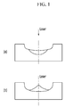
- FIG. 1 illustrates a cross-sectional shape of a groove at the time of forming an excessively melted portion and a non-uniform resolidification layer.
- a technology which forms an excessively melted portion (a) at a lower side in the groove and a central portion (b) of the resolidification layer, forms the groove in the steel sheet at a relatively low speed, and as a result, this technology has drawbacks in that it is difficult to form a groove in a surface of a grain-oriented electrical steel sheet surface which moves at a high speed of 0.9 m/s or higher, this technology cannot be applied to a material for the grain-oriented electrical steel sheet before primary recrystallization, and the resolidification layer may hinder a growth of the Goss texture at the time of annealing.
- An exemplary embodiment of the present invention has been made in an effort to provide a grain-oriented electrical steel sheet which has a surface formed with grooves to refine a magnetic domain.
- Another exemplary embodiment of the present invention provides a method of manufacturing a grain-oriented electrical steel sheet, which has a surface formed with grooves to refine a magnetic domain.
- the present invention has also been made in an effort to provide a method of manufacturing a grain-oriented electrical steel sheet which has a surface formed with grooves to refine a magnetic domain.
- An exemplary embodiment of the present invention provides a grain-oriented electrical steel sheet, which has a surface which is formed with grooves for a magnetic domain refinement treatment, in which a scattering alloy layer in the groove is eroded in a Goss texture during a recrystallization annealing process.
- T B a thickness of the scattering alloy layer on a bottom surface of the groove
- T L a thickness of the scattering alloy layer at a point that is one-half the distance between any one end of the groove and the bottom surface of the groove
- a thickness of the scattering alloy layer may be 4% to 12% of a depth of the groove.
- the depth of the groove may be 4% to 11% of a thickness of the electrical steel sheet.
- the groove may be formed diagonally with respect to a width direction of the electrical steel sheet.
- the groove may be formed at an angle greater than 0° and equal to or smaller than 5° with respect to the width direction of the electrical steel sheet.
- Three to six grooves may be intermittently formed in the width direction of the electrical steel sheet.
- Another exemplary embodiment of the present invention provides a method of manufacturing a grain-oriented electrical steel sheet, the method including: providing an electrical steel sheet before forming primary recrystallization or after forming the primary recrystallization; and forming a groove in a surface of the electrical steel sheet by radiating laser and simultaneously spraying gas onto the electrical steel sheet, in which energy density E d and a laser scanning speed V s of the radiated laser satisfy the following conditions, 1.0 J / mm 2 ⁇ Ed ⁇ 5.0 J / mm 2 , 0.0518 mm / ⁇ sec ⁇ Vs ⁇ 0.2 mm / ⁇ sec .
- Pressure of the sprayed gas may be 0.2 kg/cm 2 to 5.0 kg/cm 2 .
- An angle formed between the spray direction of the gas and the laser radiation direction may be 0° to 50°.
- a laser beam may be radiated on the surface of the electrical steel sheet at an angle greater than 0° and equal to or smaller than 5° with respect to a width direction of the electrical steel sheet.
- a movement speed V L of the electrical steel sheet may be at least 0.9 m/s.
- a light collecting shape of the laser may satisfy the following condition, 0.20 ⁇ L / d t ⁇ 1.0.
- the d t may be 50 ⁇ m or smaller.
- a scattering alloy layer in which a melted portion of the electrical steel sheet by the radiation of the laser scatters and is resolidified may be generated, and when a thickness of the scattering alloy layer on a bottom surface of the groove is defined as TB, and a thickness of the scattering alloy layer at a point that is one-half the a distance between any one end of the groove and the bottom surface of the groove is defined as TL, TB/TL may be 0.2 to 0.8.
- a thickness of the scattering alloy layer may be 4% to 12% of a depth of the groove.
- the laser In the radiating of the laser, the laser may be radiated diagonally with respect to a width direction of the electrical steel sheet.
- the laser In the radiating of the laser, the laser may be radiated at an angle greater than 0° and equal to or smaller than 5° with respect to the width direction of the electrical steel sheet.
- three to six grooves may be intermittently formed in the width direction of the electrical steel sheet.
- the groove is formed by radiating a high-speed laser beam, and as a result, it is possible to form a groove in the steel sheet on which rolling is performed at a high speed of 0.9 m/sec or higher.
- a layer melted by the radiation of the laser and resolidified is uniformly formed, thereby improving magnetism of a final product.
- magnetic domain refinement by the radiation of the laser may be performed on the electrical steel sheet before primary recrystallization or after the primary recrystallization.
- the scattering alloy layer is a texture having high energy, and in a case in which the scattering alloy layer is non-uniformly distributed, the scattering alloy layer may act as an obstruction factor to a growth a Goss texture at the time of recrystallization annealing. In addition, in a case in which the scattering alloy layer is non-uniformly distributed, the scattering alloy layer is not eroded in the Goss texture at the time of recrystallization annealing, and remains as random texturing instead of the Goss texture, thereby adversely affecting magnetism of the electrical steel sheet.
- the scattering alloy layer which is a layer formed when a melted portion melted from the electrical steel sheet by the radiation of the laser is resolidified on the steel sheet, is uniformly distributed in the groove, and as a result, the scattering alloy layer is eroded in the Goss texture at the time of recrystallization annealing, such that a fraction of the Goss texture is improved, thereby providing a grain-oriented electrical steel sheet having excellent magnetism.
- a manufacturing process of the grain-oriented electrical steel sheet is performed by allowing a slab to be subjected to hot rolling, hot rolled plate annealing, cold rolling, decarburizing annealing (primary recrystallization annealing), high temperature annealing (secondary recrystallization annealing), planarization annealing, insulation coating in sequence.
- the magnetic domain refinement treatment in the related art is performed after the insulation coating, but according to the method of manufacturing the grain-oriented electrical steel sheet according to the exemplary embodiment of the present invention, after cold rolling, before primary recrystallization or after the primary recrystallization, the magnetic domain refinement may be performed by radiating the laser to the electrical steel sheet.
- the following method of manufacturing the grain-oriented electrical steel sheet may be provided.
- the method of manufacturing the grain-oriented electrical steel sheet according to the exemplary embodiment of the present invention includes: providing an electrical steel sheet before forming primary recrystallization or after forming the primary recrystallization; and forming a groove in a surface of the electrical steel sheet by radiating laser and simultaneously spraying gas onto the electrical steel sheet.
- Energy density E d of the radiated laser may be 1.0 J/mm 2 to 5.0 J/mm 2 .
- the laser energy density exceeds 5.0 J/mm 2
- the melted portion is excessively formed, and as a result, in a final product, the scattering alloy layer is not eroded in the Goss texture, and forms random texturing.
- a value of the laser energy density which is less than 1.0 J/mm 2
- a sufficient groove depth cannot be ensured, and as a result, an effect of improving a core loss cannot be ensured after the heat treatment.
- a scanning speed V s of the radiated laser may be 0.0518 mm/ ⁇ sec to 0.2 mm/ ⁇ sec.
- a value of the scanning speed of the laser exceeds 0.2 mm/ ⁇ sec
- the scattering alloy layer is not formed, and as a result, an effect of improving a core loss cannot be ensured.
- the scanning speed of the laser is lower than 0.0518 mm/ ⁇ sec
- the melted portion is excessively formed, and as a result, in a final product, the scattering alloy layer is not eroded in the Goss texture, and forms random texturing.
- the sprayed gas may be air, inert gas, or any type of gas which does not cause oxidation of the electrical steel sheet.
- Pressure P a of the sprayed gas may be 0.2 kg/cm 2 to 5.0 kg/cm 2 .
- the pressure of the sprayed gas is lower than 0.20 kg/cm 2 , the scattering alloy layer is not formed, and as a result, an effect of improving a core loss cannot be ensured.
- the pressure of the sprayed gas exceeds 5.0 kg/cm 2 , the melted portion is excessively formed, and as a result, in a final product, the scattering alloy layer is not eroded in the Goss texture, and forms random texturing.
- An angle formed between the spray direction of the gas and the laser radiation direction may be 0° to 50° (in this case, a state in which the angle formed between the spray direction of the gas and the laser radiation direction is 0° means that the spray direction of the gas and the laser radiation direction are parallel to each other).
- the angle formed between the spray direction of the gas and the laser radiation direction affects a shape of the scattering alloy layer formed. The smaller the angle formed between the spray direction of the gas and the laser radiation direction, the smaller the thickness of the scattering alloy layer on the bottom surface of the groove, and the greater the thickness of the scattering alloy layer at an end of the groove.
- the bottom surface of the groove means the deepest portion in the groove formed in the electrical steel sheet.
- a light collecting shape of the laser may be 0.20 ⁇ L/d t ⁇ 1.0, in which d t is a beam length in a width direction(x-axis) of the electrical steel sheet, and L is a beam length in a rolling direction (y-axis).
- the d t may be 50 ⁇ m or smaller.
- a movement speed V L of the electrical steel sheet 10 may be 0.9 m/s or higher.
- the groove may be intermittently formed by being divided into three to six grooves.
- the laser may be radiated diagonally with respect to the width direction (x-axis) of the electrical steel sheet.
- an angle with respect to the width direction (x-axis) may be greater than 0° and equal to or smaller than 5°. Since the laser is diagonally radiated, it is possible to improve magnetism by decreasing a demagnetizing field.
- the depth of the groove formed as described above may be equal to or greater than 4% of the thickness of the electrical steel sheet in order to ensure a core loss improvement rate.
- the depth of the groove may be 4% to 11 % of the thickness of the electrical steel sheet.
- an average thickness of the scattering alloy layer may be 4% to 12% of the depth of the groove. In a case in which the average thickness of the scattering alloy layer is below 4% of the depth of the groove, an appropriate groove for improving a core loss is not formed, and in a case in which the average thickness of the scattering alloy layer exceeds 12% of the depth of the groove, the heat-affected zone is increased, which may have an adverse effect on a growth of the Goss texture.
- T B a thickness of the scattering alloy layer on the bottom surface of the groove
- T L a thickness of the scattering alloy layer at a point that is one-half the distance between any one end of the groove and the bottom surface of the groove
- T B /T L may be 0.2 to 1.5.
- the T B /T L may be 0.2 to 0.8, or 1.0 to 1.5. In a case in which a value of the T B /T L is below 0.2, or exceeds 1.5, non-uniformity of the scattering alloy layer is increased, which has an adverse effect on magnetism.
- the scattering alloy layer may be eroded in the Goss texture during the recrystallization annealing process.
- a heat-affected zone is included in the groove, and the heat-affected zone is not eroded in the Goss texture when the Goss texture grows during a high temperature annealing process, and remains in a shape recrystallized along the groove.
- the texture has an adverse effect on magnetism.
- the grain-oriented electrical steel sheet according to the exemplary embodiment of the present invention allows the scattering alloy layer to be uniformly distributed, such that a thermal effect is minimized, and as a result, the recrystallized texture does not remain in the groove.
- the magnetism was measured by radiating continuous wave laser on the grain-oriented electrical steel sheet having a thickness of 0.23 mm under the condition as disclosed in Table 1.
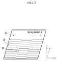
- a radiation line is illustrated as a line divided into three to six sections in the width direction as illustrated in FIG. 2 .
- a laser radiation interval was 2.50 mm, and the beam length d t in the width direction of the electrical steel sheet at the time of radiating the laser was 50 ⁇ m and had a spherical shape. In this case, the movement speed of the electrical steel sheet was 0.9 m/s.
- the grain-oriented electrical steel sheet which may obtain stable core loss characteristics even at a high movement speed of the steel sheet.
- the magnetism was measured by setting the energy density to 1.2 J/mm 2 and the depth of the groove to 15 ⁇ m, and by radiating continuous wave laser on the grain-oriented electrical steel sheet having a thickness of 0.23 mm while changing the angle with respect to the width direction of the electrical steel sheet.
- a laser radiation interval was 2.50 mm, and the beam length d t in the width direction of the electrical steel sheet at the time of radiating the laser was 50 ⁇ m and had a spherical shape.
- the movement speed of the electrical steel sheet was 0.9 m/s.
- pressure of the sprayed gas was 4.5 kg/cm 2 , and the scanning speed was 53 m/s.
- magnetism is excellent when the laser is radiated at an angle greater than 0° and equal to or smaller than 5° with respect to the width direction of the electrical steel sheet.
Landscapes
- Chemical & Material Sciences (AREA)
- Engineering & Computer Science (AREA)
- Physics & Mathematics (AREA)
- Mechanical Engineering (AREA)
- Metallurgy (AREA)
- Organic Chemistry (AREA)
- Materials Engineering (AREA)
- Crystallography & Structural Chemistry (AREA)
- Thermal Sciences (AREA)
- Electromagnetism (AREA)
- Manufacturing & Machinery (AREA)
- Optics & Photonics (AREA)
- Plasma & Fusion (AREA)
- Dispersion Chemistry (AREA)
- Power Engineering (AREA)
- Manufacturing Of Steel Electrode Plates (AREA)
- Laser Beam Processing (AREA)
- Soft Magnetic Materials (AREA)
- Powder Metallurgy (AREA)
Abstract
Description
- The present invention relates to a grain-oriented electrical steel sheet and a method of manufacturing the same.
- A grain-oriented electrical steel sheet is used as a material for an iron core of an electrical device such as an electric transformer, and a steel sheet, which has magnetic characteristics with low core loss and high magnetic flux density, is required to reduce a loss of electric power of the electrical device and improve efficiency.
- In general, the grain-oriented electrical steel sheet refers to a material having a texture (so-called "Goss texture") oriented in a rolling direction, a {110}<001> direction through hot rolling, cold rolling, and annealing processes.
- In the case of the grain-oriented electrical steel sheet, the more greatly the {110}<001> direction is oriented in an easy magnetization axis direction of iron, the better the magnetic characteristics is achieved.
- In general, the grain-oriented electrical steel sheet is manufactured by allowing a slab, which is manufactured by a continuous casting process, to be subjected to hot rolling, hot rolled plate annealing, cold rolling, decarburizing annealing, high temperature annealing, planarization annealing, insulation coating, and laser treatment processes in sequence.
- To form
uniform grooves 20 in a surface of anelectrical steel sheet 10, it is necessary to radiate continuous high power laser to the surface of the high-speedelectrical steel sheet 10, and form thegrooves 20 with accompanying melting of a base portion caused by the radiation of the laser. - A method of refining magnetic domains is used to improve magnetic characteristics of the grain-oriented electrical steel sheet, and the magnetic domain refinement method may be classified into a temporary magnetic domain refinement method and a permanent magnetic domain refinement method in accordance with whether an effect of improving magnetic domain refinement is maintained even after stress removing annealing.
- The temporary magnetic domain refinement method is a magnetic domain refinement technology that refines the magnetic domain by forming a 90° magnetic domain in order to minimize magnetic elastic energy generated by exerting local compressive stress on the surface using thermal energy or mechanical energy.
- The temporary magnetic domain refinement technology is classified into a laser magnetic domain refinement method, a ball scratch method, and a magnetic domain refinement method using plasma or ultrasonic wave in accordance with an energy source for refining the magnetic domain.
- The permanent magnetic domain refinement method, which may maintain an effect of improving a core loss even after heat treatment, may be classified into an etching method, a roll method, and a laser method.
- The etching method forms a groove in a surface of the steel sheet by an electrochemical corrosion reaction caused by an acid solution in a solution, and as a result, the etching method has drawbacks in that it is difficult to control a shape of the groove, it is difficult to ensure core loss characteristics of a final product because the groove is formed during an intermediate process (before decarburizing annealing and high temperature annealing) for producing the steel sheet, and this method is not environmentally friendly because the acid solution is used.
- The permanent magnetic domain refinement method using a roll is a magnetic domain refinement technology that forms a groove having predetermined width and depth in the surface of the steel sheet by processing a protrusion shape on the roll and using a pressing method, and generates recrystallization at a lower portion of the groove by annealing the steel sheet after forming the groove, but has drawbacks in that reliability is low such that it is difficult to ensure machining stability and stable core loss according to a thickness, and processes are complicated.
- The permanent magnetic domain refinement method using Q-Switch or pulse laser forms a groove by evaporation of a material at an irradiated portion at the time of irradiation, but has drawbacks in that it is difficult to ensure a core loss improvement rate immediately after forming the groove and before heat treatment, only a magnetic domain refinement effect caused by the simple groove is maintained even after the heat treatment, and a conveying speed of the steel sheet cannot be increased to a high speed.
- The permanent magnetic domain refinement method using continuous wave laser forms a resolidification layer only on a sidewall of the groove at the time of forming the groove, or cannot uniformly form the resolidification layer on the entire surface of the groove, such that excessive deformation is maintained at a lower base portion of the groove, and as a result, this method has drawbacks in that this method is difficult to be applied to a process before primary recrystallization, and is applied only to an iron core for a wound core electric transformer which is required to be subjected to heat treatment.
-
FIG. 1 illustrates a cross-sectional shape of a groove at the time of forming an excessively melted portion and a non-uniform resolidification layer. A technology, which forms an excessively melted portion (a) at a lower side in the groove and a central portion (b) of the resolidification layer, forms the groove in the steel sheet at a relatively low speed, and as a result, this technology has drawbacks in that it is difficult to form a groove in a surface of a grain-oriented electrical steel sheet surface which moves at a high speed of 0.9 m/s or higher, this technology cannot be applied to a material for the grain-oriented electrical steel sheet before primary recrystallization, and the resolidification layer may hinder a growth of the Goss texture at the time of annealing. - An exemplary embodiment of the present invention has been made in an effort to provide a grain-oriented electrical steel sheet which has a surface formed with grooves to refine a magnetic domain.
- Another exemplary embodiment of the present invention provides a method of manufacturing a grain-oriented electrical steel sheet, which has a surface formed with grooves to refine a magnetic domain.
- The present invention has also been made in an effort to provide a method of manufacturing a grain-oriented electrical steel sheet which has a surface formed with grooves to refine a magnetic domain. An exemplary embodiment of the present invention provides a grain-oriented electrical steel sheet, which has a surface which is formed with grooves for a magnetic domain refinement treatment, in which a scattering alloy layer in the groove is eroded in a Goss texture during a recrystallization annealing process.
- When a thickness of the scattering alloy layer on a bottom surface of the groove is defined as TB, and a thickness of the scattering alloy layer at a point that is one-half the distance between any one end of the groove and the bottom surface of the groove is defined as TL, TB/TL may be 0.2 to 0.8.
- A thickness of the scattering alloy layer may be 4% to 12% of a depth of the groove.
- The depth of the groove may be 4% to 11% of a thickness of the electrical steel sheet.
- The groove may be formed diagonally with respect to a width direction of the electrical steel sheet.
- The groove may be formed at an angle greater than 0° and equal to or smaller than 5° with respect to the width direction of the electrical steel sheet.
- Three to six grooves may be intermittently formed in the width direction of the electrical steel sheet.
- Another exemplary embodiment of the present invention provides a method of manufacturing a grain-oriented electrical steel sheet, the method including: providing an electrical steel sheet before forming primary recrystallization or after forming the primary recrystallization; and forming a groove in a surface of the electrical steel sheet by radiating laser and simultaneously spraying gas onto the electrical steel sheet, in which energy density Ed and a laser scanning speed Vs of the radiated laser satisfy the following conditions,


- Pressure of the sprayed gas may be 0.2 kg/cm2 to 5.0 kg/cm2.
- An angle formed between the spray direction of the gas and the laser radiation direction may be 0° to 50°.
- In the radiating of the laser, a laser beam may be radiated on the surface of the electrical steel sheet at an angle greater than 0° and equal to or smaller than 5° with respect to a width direction of the electrical steel sheet.
- In the radiating of the laser, a movement speed VL of the electrical steel sheet may be at least 0.9 m/s.
- In the radiating of the laser, when a beam length in the width direction of the electrical steel sheet is dt, and a beam length in a rolling direction of the electrical steel sheet is L, a light collecting shape of the laser may satisfy the following condition,

- The dt may be 50 µm or smaller.
- In the radiating of the laser, a scattering alloy layer in which a melted portion of the electrical steel sheet by the radiation of the laser scatters and is resolidified may be generated, and when a thickness of the scattering alloy layer on a bottom surface of the groove is defined as TB, and a thickness of the scattering alloy layer at a point that is one-half the a distance between any one end of the groove and the bottom surface of the groove is defined as TL, TB/TL may be 0.2 to 0.8.
- A thickness of the scattering alloy layer may be 4% to 12% of a depth of the groove.
- In the radiating of the laser, the laser may be radiated diagonally with respect to a width direction of the electrical steel sheet.
- In the radiating of the laser, the laser may be radiated at an angle greater than 0° and equal to or smaller than 5° with respect to the width direction of the electrical steel sheet.
- In the radiating of the laser, three to six grooves may be intermittently formed in the width direction of the electrical steel sheet.
- According to the method of manufacturing the grain-oriented electrical steel sheet according to the exemplary embodiment of the present invention, the groove is formed by radiating a high-speed laser beam, and as a result, it is possible to form a groove in the steel sheet on which rolling is performed at a high speed of 0.9 m/sec or higher.
- In addition, according to the method of manufacturing the grain-oriented electrical steel sheet according to the exemplary embodiment of the present invention, a layer melted by the radiation of the laser and resolidified is uniformly formed, thereby improving magnetism of a final product.
- In addition, according to the method of manufacturing the grain-oriented electrical steel sheet according to the exemplary embodiment of the present invention, magnetic domain refinement by the radiation of the laser may be performed on the electrical steel sheet before primary recrystallization or after the primary recrystallization.
- In addition, according to the method of manufacturing the grain-oriented electrical steel sheet according to the exemplary embodiment of the present invention, even though magnetic domain refinement by the radiation of the laser is performed on the electrical steel sheet before primary recrystallization, an effect of improving a core loss is maintained even after a subsequent heat treatment process.
-
-
FIG. 1 is a view illustrating a groove formed in a surface of a steel sheet by a magnetic domain refinement method according to the related art. -
FIG. 2 is a view illustrating shapes of grooves on an XY plane which are formed in a surface of a steel sheet when laser is radiated on the surface of the steel sheet. -
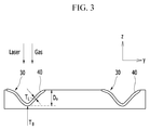
FIG. 3 is a view illustrating a cross section (YZ plane) of apart 30 of the continuous groove illustrated inFIG. 2 . - Advantages and features of the present invention and methods of achieving the advantages and features will be clear with reference to exemplary embodiments described in detail below together with the accompanying drawings. However, the present invention is not limited to the exemplary embodiments set forth below, and may be embodied in various other forms. The present exemplary embodiments are for rendering the disclosure of the present invention complete and are set forth to provide a complete understanding of the scope of the invention to a person with ordinary skill in the technical field to which the present invention pertains, and the present invention will only be defined by the scope of the claims. Like reference numerals indicate like elements throughout the specification.
- Therefore, in some exemplary embodiments, well-known technologies will not be specifically described in order to avoid obscuring the present invention. Unless there are other definitions, all terms used in the present specification (including technical and scientific terms) have the meanings that those having ordinary skill in the technical field to which the present invention pertains typically understand. Unless explicitly described to the contrary, the word "comprise" and variations such as "comprises" or "comprising", will be understood to imply the inclusion of stated elements but not the exclusion of any other elements. In addition, singular expressions used herein may include plural expressions unless they have definitely opposite meanings.
- A scattering alloy layer in which a melted portion, which has been melted from an electrical steel sheet by the laser, is resolidified on the steel sheet exists in a groove formed by magnetic domain refinement by radiation of laser.
- The scattering alloy layer is a texture having high energy, and in a case in which the scattering alloy layer is non-uniformly distributed, the scattering alloy layer may act as an obstruction factor to a growth a Goss texture at the time of recrystallization annealing. In addition, in a case in which the scattering alloy layer is non-uniformly distributed, the scattering alloy layer is not eroded in the Goss texture at the time of recrystallization annealing, and remains as random texturing instead of the Goss texture, thereby adversely affecting magnetism of the electrical steel sheet.
- According to a method of manufacturing a grain-oriented electrical steel sheet according to an exemplary embodiment of the present invention, the scattering alloy layer, which is a layer formed when a melted portion melted from the electrical steel sheet by the radiation of the laser is resolidified on the steel sheet, is uniformly distributed in the groove, and as a result, the scattering alloy layer is eroded in the Goss texture at the time of recrystallization annealing, such that a fraction of the Goss texture is improved, thereby providing a grain-oriented electrical steel sheet having excellent magnetism.
- In general, a manufacturing process of the grain-oriented electrical steel sheet is performed by allowing a slab to be subjected to hot rolling, hot rolled plate annealing, cold rolling, decarburizing annealing (primary recrystallization annealing), high temperature annealing (secondary recrystallization annealing), planarization annealing, insulation coating in sequence.
- The magnetic domain refinement treatment in the related art is performed after the insulation coating, but according to the method of manufacturing the grain-oriented electrical steel sheet according to the exemplary embodiment of the present invention, after cold rolling, before primary recrystallization or after the primary recrystallization, the magnetic domain refinement may be performed by radiating the laser to the electrical steel sheet.
- In addition, even though the magnetic domain refinement is performed by radiating the laser to the electrical steel sheet before the primary recrystallization, an effect of improving a core loss is maintained even after a subsequent heat treatment process.
- To provide the aforementioned method of manufacturing the grain-oriented electrical steel sheet, the following method of manufacturing the grain-oriented electrical steel sheet may be provided.
- The method of manufacturing the grain-oriented electrical steel sheet according to the exemplary embodiment of the present invention includes: providing an electrical steel sheet before forming primary recrystallization or after forming the primary recrystallization; and forming a groove in a surface of the electrical steel sheet by radiating laser and simultaneously spraying gas onto the electrical steel sheet.
- Energy density Ed of the radiated laser may be 1.0 J/mm2 to 5.0 J/mm2. In a case in which the laser energy density exceeds 5.0 J/mm2, the melted portion is excessively formed, and as a result, in a final product, the scattering alloy layer is not eroded in the Goss texture, and forms random texturing. In the case of a value of the laser energy density which is less than 1.0 J/mm2, a sufficient groove depth cannot be ensured, and as a result, an effect of improving a core loss cannot be ensured after the heat treatment.
- A scanning speed Vs of the radiated laser may be 0.0518 mm/µsec to 0.2 mm/µsec. In a case in which a value of the scanning speed of the laser exceeds 0.2 mm/µsec, the scattering alloy layer is not formed, and as a result, an effect of improving a core loss cannot be ensured. In addition, in a case in which the scanning speed of the laser is lower than 0.0518 mm/µsec, the melted portion is excessively formed, and as a result, in a final product, the scattering alloy layer is not eroded in the Goss texture, and forms random texturing.
- The sprayed gas may be air, inert gas, or any type of gas which does not cause oxidation of the electrical steel sheet.
- Pressure Pa of the sprayed gas may be 0.2 kg/cm2 to 5.0 kg/cm2. In a case in which the pressure of the sprayed gas is lower than 0.20 kg/cm2, the scattering alloy layer is not formed, and as a result, an effect of improving a core loss cannot be ensured. In addition, in a case in which the pressure of the sprayed gas exceeds 5.0 kg/cm2, the melted portion is excessively formed, and as a result, in a final product, the scattering alloy layer is not eroded in the Goss texture, and forms random texturing.
- An angle formed between the spray direction of the gas and the laser radiation direction may be 0° to 50° (in this case, a state in which the angle formed between the spray direction of the gas and the laser radiation direction is 0° means that the spray direction of the gas and the laser radiation direction are parallel to each other). The angle formed between the spray direction of the gas and the laser radiation direction affects a shape of the scattering alloy layer formed. The smaller the angle formed between the spray direction of the gas and the laser radiation direction, the smaller the thickness of the scattering alloy layer on the bottom surface of the groove, and the greater the thickness of the scattering alloy layer at an end of the groove.
- Here, the bottom surface of the groove means the deepest portion in the groove formed in the electrical steel sheet.
- In addition, a light collecting shape of the laser may be 0.20 ≤ L/dt ≤ 1.0, in which dt is a beam length in a width direction(x-axis) of the electrical steel sheet, and L is a beam length in a rolling direction (y-axis). In addition, the dt may be 50 µm or smaller.
- In a case in which the L/dt value exceeds 1.0, a heat-affected zone in the rolling direction is increased, thereby adversely affecting a growth of the Goss texture, and in a case in which the L/dt is below 0.20, a width of the groove in the rolling direction is narrow, and the melted portion does not scatter, such that it is impossible to ensure a sufficient groove depth.
- Under the above condition, a movement speed VL of the
electrical steel sheet 10 may be 0.9 m/s or higher. - In addition, the groove may be intermittently formed by being divided into three to six grooves.
- In addition, the laser may be radiated diagonally with respect to the width direction (x-axis) of the electrical steel sheet. In addition, an angle with respect to the width direction (x-axis) may be greater than 0° and equal to or smaller than 5°. Since the laser is diagonally radiated, it is possible to improve magnetism by decreasing a demagnetizing field.
- The depth of the groove formed as described above may be equal to or greater than 4% of the thickness of the electrical steel sheet in order to ensure a core loss improvement rate. Alternatively, the depth of the groove may be 4% to 11 % of the thickness of the electrical steel sheet.
- In addition, an average thickness of the scattering alloy layer may be 4% to 12% of the depth of the groove. In a case in which the average thickness of the scattering alloy layer is below 4% of the depth of the groove, an appropriate groove for improving a core loss is not formed, and in a case in which the average thickness of the scattering alloy layer exceeds 12% of the depth of the groove, the heat-affected zone is increased, which may have an adverse effect on a growth of the Goss texture.
- In addition, when a thickness of the scattering alloy layer on the bottom surface of the groove is defined as TB, and a thickness of the scattering alloy layer at a point that is one-half the distance between any one end of the groove and the bottom surface of the groove is defined as TL, TB/TL may be 0.2 to 1.5. Alternatively, the TB/TL may be 0.2 to 0.8, or 1.0 to 1.5. In a case in which a value of the TB/TL is below 0.2, or exceeds 1.5, non-uniformity of the scattering alloy layer is increased, which has an adverse effect on magnetism.
- In the case of the electrical steel sheet on which the recrystallization annealing has been performed under the aforementioned magnetic domain refinement condition, the scattering alloy layer may be eroded in the Goss texture during the recrystallization annealing process. In general, at the time of the magnetic domain refinement treatment of the grain-oriented electrical steel sheet, a heat-affected zone is included in the groove, and the heat-affected zone is not eroded in the Goss texture when the Goss texture grows during a high temperature annealing process, and remains in a shape recrystallized along the groove. The texture has an adverse effect on magnetism.
- However, the grain-oriented electrical steel sheet according to the exemplary embodiment of the present invention allows the scattering alloy layer to be uniformly distributed, such that a thermal effect is minimized, and as a result, the recrystallized texture does not remain in the groove.
- Hereinafter, the present invention will be described in detail with reference to Examples. However, the following Examples are intended for the purpose of illustration of the present invention, and the contents of the present invention are not limited by the following Examples.
- The magnetism was measured by radiating continuous wave laser on the grain-oriented electrical steel sheet having a thickness of 0.23 mm under the condition as disclosed in Table 1. A radiation line is illustrated as a line divided into three to six sections in the width direction as illustrated in
FIG. 2 . A laser radiation interval was 2.50 mm, and the beam length dt in the width direction of the electrical steel sheet at the time of radiating the laser was 50 µm and had a spherical shape. In this case, the movement speed of the electrical steel sheet was 0.9 m/s.Table 1 Ed J/m m2 DH µm TL/TB Average thickness of scattering alloy layer µm Pa Kgf /cm2 Vs m/s Before radiating laser W17/50 Before heat treatment W17/50 Before heat treatment W17/50 Comparison 1.0 10.0 0.3 1.2 0.2 51.8 0.82 0.78 0.78 Example 11.0 0.4 1.1 5.0 51.8 0.82 0.75 0.74 Example 6.4 0.2 0.768 5.0 200 0.82 0.79 0.79 Example 5.0 21.0 0.7 1.26 0.2 51.8 0.82 0.70 0.69 Example 22.2 0.8 0.9 5.0 51.8 0.82 0.71 0.71 Example 15.3 0.5 1.224 5.0 200 0.82 0.69 0.69 Example 1.2 15 0.5 0.6 61. 0 51.8 0.83 0.68 0.68 Example 20 0.6 1.6 51.8 0.82 0.67 0.67 Example 25 0.7 3 200 0.83 0.68 0.67 Example 5.3 25.5 0.85 1.5 5.0 51.8 0.82 0.86 0.82 Comparative Example 1.8 5.0 51.8 0.82 0.87 0.83 Comparative Example 0.5 5.0 200 0.82 0.85 0.83 Comparative Example - In the laser radiation condition range according to the present invention, it is possible to provide the grain-oriented electrical steel sheet, which may obtain stable core loss characteristics even at a high movement speed of the steel sheet.
- The magnetism was measured by setting the energy density to 1.2 J/mm2 and the depth of the groove to 15 µm, and by radiating continuous wave laser on the grain-oriented electrical steel sheet having a thickness of 0.23 mm while changing the angle with respect to the width direction of the electrical steel sheet. A laser radiation interval was 2.50 mm, and the beam length dt in the width direction of the electrical steel sheet at the time of radiating the laser was 50 µm and had a spherical shape. In this case, the movement speed of the electrical steel sheet was 0.9 m/s. In addition, pressure of the sprayed gas was 4.5 kg/cm2, and the scanning speed was 53 m/s.
Table 2 Radiation Not treated by laser Before heat treatment After heat treatment Comparison Angle core loss (W17/50)/magnetic flux density B8 core loss (W17/50)/magnetic flux density B8 core loss (W17/50)/magnetic flux density B8 0 0.82/1.92 0.67/1.89 0.67/1.90 Example 3 0.83/1.92 0.68/1.905 0.68/1.910 Example 5 0.82/1.92 0.67/1.907 0.67/1.915 Example 7 1.07/1.34 0.88/1.330 0.88/1.330 Comparative Example 9 1.16/1.34 0.92/1.320 0.92/1.320 Comparative Example - As can be seen from Table 2, magnetism is excellent when the laser is radiated at an angle greater than 0° and equal to or smaller than 5° with respect to the width direction of the electrical steel sheet.
- The exemplary embodiment of the present invention has been described with reference to the accompanying drawings, but those skilled in the art will understand that the present invention may be implemented in any other specific form without changing the technical spirit or an essential feature thereof.
- Thus, it should be appreciated that the exemplary embodiments described above are intended to be illustrative in every sense, and not restrictive. The scope of the present invention is represented by the claims to be described below rather than the detailed description, and it should be interpreted that all the changes or modified forms, which are derived from the meaning and the scope of the claims, and the equivalents thereto, are included in the scope of the present invention.
-
- 10:
- Electrical steel sheet
- 20:
- Groove
- 30:
- Part of continuous groove
- 40:
- Scattering alloy layer
Claims (19)
- A grain-oriented electrical steel sheet, which has a surface which is formed with grooves for a magnetic domain refinement treatment,
wherein a scattering alloy layer in the groove is eroded in a Goss texture during a recrystallization annealing process. - The grain-oriented electrical steel sheet of claim 1, wherein:when a thickness of the scattering alloy layer on a bottom surface of the groove is defined as TB, and a thickness of the scattering alloy layer at a point that is one-half the distance between any one end of the groove and the bottom surface of the groove is defined as TL, TB/TL is 0.2 to 0.8.
- The grain-oriented electrical steel sheet of claim 2, wherein:a thickness of the scattering alloy layer is 4% to 12% of a depth of the groove.
- The grain-oriented electrical steel sheet of claim 3, wherein:the depth of the groove is 4% to 11% of a thickness of the electrical steel sheet.
- The grain-oriented electrical steel sheet of claim 4, wherein:the groove is formed diagonally with respect to a width direction of the electrical steel sheet.
- The grain-oriented electrical steel sheet of claim 5, wherein:the groove is formed at an angle greater than 0° and equal to or smaller than 5° with respect to the width direction of the electrical steel sheet.
- The grain-oriented electrical steel sheet of claim 6, wherein:three to six grooves are intermittently formed in the width direction of the electrical steel sheet.
- A method of manufacturing a grain-oriented electrical steel sheet, the method comprising:providing electrical steel sheet before forming primary recrystallization or after forming the primary recrystallization; andforming a groove in a surface of the electrical steel sheet by radiating laser and simultaneously spraying gas onto the electrical steel sheet,wherein energy density Ed and a laser scanning speed Vs of the radiated laser satisfy the following conditions,


- The method of claim 7, wherein:pressure of the sprayed gas is 0.2 kg/cm2 to 5.0 kg/cm2.
- The method of claim 9, wherein:an angle formed between the spray direction of the gas and the laser radiation direction is 0° to 50° (here, a state in which the angle formed between the spray direction of the gas and the laser radiation direction is 0° means that the spray direction of the gas and the laser radiation direction are parallel to each other).
- The method of claim 10, wherein:in the radiating of the laser, a laser beam is radiated on the surface of the electrical steel sheet at an angle greater than 0° and equal to or smaller than 5° with respect to a width direction of the electrical steel sheet.
- The method of claim 11, wherein:in the radiating of the laser, a movement speed VL of the electrical steel sheet is at least 0.9 m/s.
- The method of claim 12, wherein:in the radiating of the laser,when a beam length in the width direction of the electrical steel sheet is dt, and a beam length in a rolling direction of the electrical steel sheet is L, a light collecting shape of the laser satisfies the following condition,

- The method of claim 13, wherein:dt is 50 µm or smaller.
- The method of claim 14, wherein:in the radiating of the laser,a scattering alloy layer in which a melted portion of the electrical steel sheet by the radiation of the laser scatters and is resolidified is generated, and when a thickness of the scattering alloy layer on a bottom surface of the groove is defined as TB, and a thickness of the scattering alloy layer at a point that is one-half the distance between any one end of the groove and the bottom surface of the groove is defined as TL, TB/TL is 0.2 to 0.8.
- The method of claim 15, wherein:a thickness of the scattering alloy layer is 4% to 12% of a depth of the groove.
- The method of claim 16, wherein:in the radiating of the laser,the laser is radiated diagonally with respect to a width direction of the electrical steel sheet.
- The method of claim 17, wherein:in the radiating of the laser,the laser is radiated at an angle greater than 0° and equal to or smaller than 5° with respect to the width direction of the electrical steel sheet.
- The method of claim 18, wherein:in the radiating of the laser,three to six grooves are intermittently formed in the width direction of the electrical steel sheet.
Priority Applications (1)
| Application Number | Priority Date | Filing Date | Title |
|---|---|---|---|
| PL14828826T PL3025797T3 (en) | 2013-07-24 | 2014-07-22 | Grain-oriented electrical steel sheet and method of its production |
Applications Claiming Priority (2)
| Application Number | Priority Date | Filing Date | Title |
|---|---|---|---|
| KR20130087416 | 2013-07-24 | ||
| PCT/KR2014/006638 WO2015012562A1 (en) | 2013-07-24 | 2014-07-22 | Directional electric steel plate and method for manufacturing same |
Publications (3)
| Publication Number | Publication Date |
|---|---|
| EP3025797A1 true EP3025797A1 (en) | 2016-06-01 |
| EP3025797A4 EP3025797A4 (en) | 2017-02-08 |
| EP3025797B1 EP3025797B1 (en) | 2018-03-14 |
Family
ID=52393531
Family Applications (1)
| Application Number | Title | Priority Date | Filing Date |
|---|---|---|---|
| EP14828826.9A Active EP3025797B1 (en) | 2013-07-24 | 2014-07-22 | Grain-oriented electrical steel sheet and method for manufacturing same |
Country Status (9)
| Country | Link |
|---|---|
| US (1) | US10793929B2 (en) |
| EP (1) | EP3025797B1 (en) |
| JP (1) | JP6405378B2 (en) |
| KR (2) | KR20150012205A (en) |
| CN (1) | CN105451902B (en) |
| PL (1) | PL3025797T3 (en) |
| SG (1) | SG11201600558VA (en) |
| TR (1) | TR201808211T4 (en) |
| WO (1) | WO2015012562A1 (en) |
Cited By (5)
| Publication number | Priority date | Publication date | Assignee | Title |
|---|---|---|---|---|
| EP3733881A4 (en) * | 2017-12-26 | 2020-11-11 | Posco | GRAIN ORIENTED ELECTRIC STEEL SHEET AND MAGNETIC DOMAIN REFINEMENT PROCESS FOR IT |
| EP3751014A4 (en) * | 2018-02-08 | 2021-10-06 | Nippon Steel Corporation | ORIENTED GRAIN ELECTRIC STEEL SHEET |
| EP3748020A4 (en) * | 2018-01-31 | 2021-10-13 | Nippon Steel Corporation | ORIENTED ELECTROMAGNETIC STEEL SHEET |
| EP3901969A4 (en) * | 2018-12-19 | 2022-03-09 | Posco | ORIENTATED ELECTRICAL STEEL SHEET AND METHOD FOR PRODUCTION THEREOF |
| US11318562B2 (en) | 2016-12-22 | 2022-05-03 | Posco | Grain-oriented electrical steel sheet and magnetic domain refinement method therefor |
Families Citing this family (16)
| Publication number | Priority date | Publication date | Assignee | Title |
|---|---|---|---|---|
| CN106282512B (en) * | 2015-05-11 | 2018-03-30 | 宝山钢铁股份有限公司 | Low noise level transformer orientation silicon steel piece making method |
| CN105463172A (en) * | 2015-12-14 | 2016-04-06 | 武汉钢铁(集团)公司 | Method for improving magnetic performance of silicon steel sheet through laser indented oriented silicon steel cold-rolled sheet |
| KR102466499B1 (en) * | 2015-12-22 | 2022-11-10 | 주식회사 포스코 | Grain oriented electrical steel sheet and manufacturing method for the same |
| KR101751525B1 (en) | 2015-12-24 | 2017-07-11 | 주식회사 포스코 | Grain oriented electrical steel sheet and method for manufacturing the same |
| WO2019156127A1 (en) | 2018-02-09 | 2019-08-15 | 日本製鉄株式会社 | Oriented electromagnetic steel sheet and production method therefor |
| CN110323044B (en) * | 2018-03-30 | 2021-02-19 | 宝山钢铁股份有限公司 | Heat-resistant magnetic domain refining type oriented silicon steel and manufacturing method thereof |
| KR102091631B1 (en) * | 2018-08-28 | 2020-03-20 | 주식회사 포스코 | Grain oriented electrical steel sheet and method for refining magnetic domains therein |
| KR102104554B1 (en) | 2018-09-21 | 2020-04-24 | 주식회사 포스코 | Grain oriented electrical steel sheet and method for refining magnetic domains therein |
| KR102149826B1 (en) * | 2018-12-19 | 2020-08-31 | 주식회사 포스코 | Grain oriented electrical steel sheet and method for manufacturing the same |
| KR102326327B1 (en) * | 2019-12-20 | 2021-11-12 | 주식회사 포스코 | Grain oriented electrical steel sheet and manufacturing method of the same |
| KR102428854B1 (en) * | 2019-12-20 | 2022-08-02 | 주식회사 포스코 | Grain oriented electrical steel sheet and method for refining magnetic domains therein |
| KR102871714B1 (en) * | 2020-01-06 | 2025-10-15 | 동우 화인켐 주식회사 | Touch sensor and method of manufacturing the same |
| KR102820621B1 (en) * | 2020-07-15 | 2025-06-13 | 닛폰세이테츠 가부시키가이샤 | Grain-oriented electrical steel sheet and method for manufacturing grain-oriented electrical steel sheet |
| JP7435486B2 (en) * | 2021-01-18 | 2024-02-21 | Jfeスチール株式会社 | Grain-oriented electrical steel sheet and its manufacturing method |
| JP7639805B2 (en) * | 2022-02-18 | 2025-03-05 | Jfeスチール株式会社 | Grain-oriented electrical steel sheet |
| CN120322574A (en) | 2022-11-22 | 2025-07-15 | 日本制铁株式会社 | Grain-oriented electrical steel sheet and method for producing the same |
Family Cites Families (21)
| Publication number | Priority date | Publication date | Assignee | Title |
|---|---|---|---|---|
| JPH0740527B2 (en) * | 1984-09-21 | 1995-05-01 | 新日本製鐵株式会社 | Directional electrical steel sheet subjected to magnetic domain control treatment and method of manufacturing the same |
| IT1182608B (en) * | 1984-10-15 | 1987-10-05 | Nippon Steel Corp | ORIENTED GRAIN ELECTRIC STEEL SHEET WITH LOW POWER LOSS AND METHOD FOR ITS MANUFACTURE |
| KR940005812B1 (en) * | 1990-12-10 | 1994-06-23 | 전종웅 | Vinyl chloride coated bar material and its manufacturing method |
| KR960009170B1 (en) | 1992-07-02 | 1996-07-16 | Nippon Steel Corp | Grain oriented electrical steel sheet having high magnetic flux density and ultra iron loss and process for producing the same |
| KR960010595B1 (en) | 1992-09-21 | 1996-08-06 | 신니뽄세이데스 가부시끼가이샤 | Production of grain-oriented silicon steel sheet having no glass coating and excellent in iron loss |
| JP2002220642A (en) | 2001-01-29 | 2002-08-09 | Kawasaki Steel Corp | Grain-oriented electrical steel sheet with low iron loss and method of manufacturing the same |
| JP2002292484A (en) * | 2001-03-30 | 2002-10-08 | Nippon Steel Corp | Groove processing device by laser |
| JP4384451B2 (en) * | 2003-08-14 | 2009-12-16 | 新日本製鐵株式会社 | Oriented electrical steel sheet with excellent magnetic properties and method for producing the same |
| JP4616623B2 (en) * | 2004-11-18 | 2011-01-19 | 新日本製鐵株式会社 | Method for producing grain-oriented electrical steel sheet |
| TWI305548B (en) * | 2005-05-09 | 2009-01-21 | Nippon Steel Corp | Low core loss grain-oriented electrical steel sheet and method for producing the same |
| WO2009104521A1 (en) * | 2008-02-19 | 2009-08-27 | 新日本製鐵株式会社 | Low core loss unidirectional electromagnetic steel plate and method of manufacturing the same |
| JP5234222B2 (en) * | 2010-04-01 | 2013-07-10 | 新日鐵住金株式会社 | Oriented electrical steel sheet and manufacturing method thereof |
| JP4782248B1 (en) * | 2010-07-28 | 2011-09-28 | 新日本製鐵株式会社 | Oriented electrical steel sheet and manufacturing method thereof |
| BR112013005335B1 (en) * | 2010-09-09 | 2018-10-23 | Nippon Steel & Sumitomo Metal Corporation | grain oriented electric steel sheet and method for manufacturing it |
| BR112013005450B1 (en) * | 2010-09-10 | 2019-05-07 | Jfe Steel Corporation | ELECTRIC STEEL SHEET WITH ORIENTED GRAIN AND METHOD FOR PRODUCTION OF THE SAME. |
| JP5423646B2 (en) | 2010-10-15 | 2014-02-19 | 新日鐵住金株式会社 | Method for producing grain-oriented electrical steel sheet |
| BR112013030412B1 (en) | 2011-05-27 | 2019-10-29 | Nippon Steel & Sumitomo Metal Corp | grain oriented electromagnetic steel sheet and manufacturing method grain oriented electromagnetic steel sheet |
| JP5782527B2 (en) | 2011-12-19 | 2015-09-24 | ポスコ | Low iron loss high magnetic flux density grained electrical steel sheet and manufacturing method thereof |
| KR101370634B1 (en) * | 2011-12-29 | 2014-03-07 | 주식회사 포스코 | Grain-oriented electrical steel sheet and method for manufacturing the same |
| US10131018B2 (en) * | 2012-04-27 | 2018-11-20 | Nippon Steel & Sumitomo Metal Corporation | Grain-oriented magnetic steel sheet and method of producing the same |
| CN102941413B (en) * | 2012-11-23 | 2015-07-01 | 武汉钢铁(集团)公司 | Method for reducing iron loss of oriented silicon steel through multiple times of laser grooving |
-
2014
- 2014-07-22 WO PCT/KR2014/006638 patent/WO2015012562A1/en not_active Ceased
- 2014-07-22 US US14/907,046 patent/US10793929B2/en active Active
- 2014-07-22 PL PL14828826T patent/PL3025797T3/en unknown
- 2014-07-22 CN CN201480041982.7A patent/CN105451902B/en active Active
- 2014-07-22 TR TR2018/08211T patent/TR201808211T4/en unknown
- 2014-07-22 SG SG11201600558VA patent/SG11201600558VA/en unknown
- 2014-07-22 JP JP2016529705A patent/JP6405378B2/en active Active
- 2014-07-22 EP EP14828826.9A patent/EP3025797B1/en active Active
- 2014-07-22 KR KR1020140092366A patent/KR20150012205A/en not_active Ceased
-
2021
- 2021-04-28 KR KR1020210055138A patent/KR102288802B1/en active Active
Cited By (8)
| Publication number | Priority date | Publication date | Assignee | Title |
|---|---|---|---|---|
| US11318562B2 (en) | 2016-12-22 | 2022-05-03 | Posco | Grain-oriented electrical steel sheet and magnetic domain refinement method therefor |
| US11772199B2 (en) | 2016-12-22 | 2023-10-03 | Posco | Grain-oriented electrical steel sheet and magnetic domain refinement method therefor |
| EP3733881A4 (en) * | 2017-12-26 | 2020-11-11 | Posco | GRAIN ORIENTED ELECTRIC STEEL SHEET AND MAGNETIC DOMAIN REFINEMENT PROCESS FOR IT |
| US11772189B2 (en) | 2017-12-26 | 2023-10-03 | Posco Co., Ltd | Grain-oriented electrical steel sheet and magnetic domain refining method therefor |
| EP3748020A4 (en) * | 2018-01-31 | 2021-10-13 | Nippon Steel Corporation | ORIENTED ELECTROMAGNETIC STEEL SHEET |
| EP3751014A4 (en) * | 2018-02-08 | 2021-10-06 | Nippon Steel Corporation | ORIENTED GRAIN ELECTRIC STEEL SHEET |
| EP3901969A4 (en) * | 2018-12-19 | 2022-03-09 | Posco | ORIENTATED ELECTRICAL STEEL SHEET AND METHOD FOR PRODUCTION THEREOF |
| US12051529B2 (en) | 2018-12-19 | 2024-07-30 | Posco Co., Ltd | Oriented electrical steel sheet and method for producing same |
Also Published As
| Publication number | Publication date |
|---|---|
| SG11201600558VA (en) | 2016-02-26 |
| JP2016532776A (en) | 2016-10-20 |
| TR201808211T4 (en) | 2018-07-23 |
| PL3025797T3 (en) | 2018-09-28 |
| KR102288802B1 (en) | 2021-08-11 |
| WO2015012562A1 (en) | 2015-01-29 |
| EP3025797B1 (en) | 2018-03-14 |
| CN105451902A (en) | 2016-03-30 |
| US10793929B2 (en) | 2020-10-06 |
| US20160177413A1 (en) | 2016-06-23 |
| KR20210052420A (en) | 2021-05-10 |
| KR20150012205A (en) | 2015-02-03 |
| EP3025797A4 (en) | 2017-02-08 |
| CN105451902B (en) | 2018-08-24 |
| WO2015012562A8 (en) | 2015-04-16 |
| JP6405378B2 (en) | 2018-10-17 |
Similar Documents
| Publication | Publication Date | Title |
|---|---|---|
| EP3025797B1 (en) | Grain-oriented electrical steel sheet and method for manufacturing same | |
| JP7245285B2 (en) | Grain-oriented electrical steel sheet and its magnetic domain refinement method | |
| EP3395963B1 (en) | Grain-oriented electrical steel sheet and method for manufacturing same | |
| KR101719231B1 (en) | Grain oriented electical steel sheet and method for manufacturing the same | |
| KR102133909B1 (en) | Grain oriented electrical steel sheet and method for manufacturing the same | |
| KR101659350B1 (en) | Grain-oriented electrical steel sheet and method for manufacturing the same | |
| EP2918689B1 (en) | Laser processing apparatus and laser irradiation method | |
| EP3733881B1 (en) | Grain-oriented electrical steel sheet and magnetic domain refining method therefor | |
| KR102428854B1 (en) | Grain oriented electrical steel sheet and method for refining magnetic domains therein | |
| KR102276850B1 (en) | Grain oriented electrical steel sheet and method for refining magnetic domains therein | |
| EP3855458B9 (en) | Magnetic domain refinement method for grain-oriented electrical steels | |
| EP3901970B1 (en) | Oriented electrical steel sheet and method for manufacturing same | |
| EP3901969A1 (en) | Oriented electrical steel sheet and method for producing same | |
| KR20150062034A (en) | Grain-oriented electrical steel sheet and method for manufacturing the same | |
| KR20160078180A (en) | Grain-orientied electrical steel sheet and method for manufacturing the same | |
| KR20200024658A (en) | Grain oriented electrical steel sheet and method for refining magnetic domains therein |
Legal Events
| Date | Code | Title | Description |
|---|---|---|---|
| PUAI | Public reference made under article 153(3) epc to a published international application that has entered the european phase |
Free format text: ORIGINAL CODE: 0009012 |
|
| 17P | Request for examination filed |
Effective date: 20160222 |
|
| AK | Designated contracting states |
Kind code of ref document: A1 Designated state(s): AL AT BE BG CH CY CZ DE DK EE ES FI FR GB GR HR HU IE IS IT LI LT LU LV MC MK MT NL NO PL PT RO RS SE SI SK SM TR |
|
| AX | Request for extension of the european patent |
Extension state: BA ME |
|
| DAX | Request for extension of the european patent (deleted) | ||
| A4 | Supplementary search report drawn up and despatched |
Effective date: 20170111 |
|
| RIC1 | Information provided on ipc code assigned before grant |
Ipc: C22C 38/02 20060101ALI20170104BHEP Ipc: B23K 26/00 20140101ALI20170104BHEP Ipc: C21D 10/00 20060101ALI20170104BHEP Ipc: B21B 1/22 20060101AFI20170104BHEP |
|
| GRAP | Despatch of communication of intention to grant a patent |
Free format text: ORIGINAL CODE: EPIDOSNIGR1 |
|
| INTG | Intention to grant announced |
Effective date: 20170922 |
|
| GRAS | Grant fee paid |
Free format text: ORIGINAL CODE: EPIDOSNIGR3 |
|
| GRAA | (expected) grant |
Free format text: ORIGINAL CODE: 0009210 |
|
| AK | Designated contracting states |
Kind code of ref document: B1 Designated state(s): AL AT BE BG CH CY CZ DE DK EE ES FI FR GB GR HR HU IE IS IT LI LT LU LV MC MK MT NL NO PL PT RO RS SE SI SK SM TR |
|
| REG | Reference to a national code |
Ref country code: GB Ref legal event code: FG4D |
|
| REG | Reference to a national code |
Ref country code: CH Ref legal event code: EP Ref country code: AT Ref legal event code: REF Ref document number: 978341 Country of ref document: AT Kind code of ref document: T Effective date: 20180315 |
|
| REG | Reference to a national code |
Ref country code: IE Ref legal event code: FG4D |
|
| REG | Reference to a national code |
Ref country code: DE Ref legal event code: R096 Ref document number: 602014022432 Country of ref document: DE |
|
| REG | Reference to a national code |
Ref country code: FR Ref legal event code: PLFP Year of fee payment: 5 |
|
| REG | Reference to a national code |
Ref country code: NL Ref legal event code: MP Effective date: 20180314 |
|
| REG | Reference to a national code |
Ref country code: LT Ref legal event code: MG4D |
|
| PG25 | Lapsed in a contracting state [announced via postgrant information from national office to epo] |
Ref country code: NO Free format text: LAPSE BECAUSE OF FAILURE TO SUBMIT A TRANSLATION OF THE DESCRIPTION OR TO PAY THE FEE WITHIN THE PRESCRIBED TIME-LIMIT Effective date: 20180614 Ref country code: CY Free format text: LAPSE BECAUSE OF FAILURE TO SUBMIT A TRANSLATION OF THE DESCRIPTION OR TO PAY THE FEE WITHIN THE PRESCRIBED TIME-LIMIT Effective date: 20180314 Ref country code: LT Free format text: LAPSE BECAUSE OF FAILURE TO SUBMIT A TRANSLATION OF THE DESCRIPTION OR TO PAY THE FEE WITHIN THE PRESCRIBED TIME-LIMIT Effective date: 20180314 Ref country code: FI Free format text: LAPSE BECAUSE OF FAILURE TO SUBMIT A TRANSLATION OF THE DESCRIPTION OR TO PAY THE FEE WITHIN THE PRESCRIBED TIME-LIMIT Effective date: 20180314 Ref country code: HR Free format text: LAPSE BECAUSE OF FAILURE TO SUBMIT A TRANSLATION OF THE DESCRIPTION OR TO PAY THE FEE WITHIN THE PRESCRIBED TIME-LIMIT Effective date: 20180314 |
|
| PG25 | Lapsed in a contracting state [announced via postgrant information from national office to epo] |
Ref country code: RS Free format text: LAPSE BECAUSE OF FAILURE TO SUBMIT A TRANSLATION OF THE DESCRIPTION OR TO PAY THE FEE WITHIN THE PRESCRIBED TIME-LIMIT Effective date: 20180314 Ref country code: SE Free format text: LAPSE BECAUSE OF FAILURE TO SUBMIT A TRANSLATION OF THE DESCRIPTION OR TO PAY THE FEE WITHIN THE PRESCRIBED TIME-LIMIT Effective date: 20180314 Ref country code: BG Free format text: LAPSE BECAUSE OF FAILURE TO SUBMIT A TRANSLATION OF THE DESCRIPTION OR TO PAY THE FEE WITHIN THE PRESCRIBED TIME-LIMIT Effective date: 20180614 Ref country code: LV Free format text: LAPSE BECAUSE OF FAILURE TO SUBMIT A TRANSLATION OF THE DESCRIPTION OR TO PAY THE FEE WITHIN THE PRESCRIBED TIME-LIMIT Effective date: 20180314 Ref country code: GR Free format text: LAPSE BECAUSE OF FAILURE TO SUBMIT A TRANSLATION OF THE DESCRIPTION OR TO PAY THE FEE WITHIN THE PRESCRIBED TIME-LIMIT Effective date: 20180615 |
|
| PG25 | Lapsed in a contracting state [announced via postgrant information from national office to epo] |
Ref country code: EE Free format text: LAPSE BECAUSE OF FAILURE TO SUBMIT A TRANSLATION OF THE DESCRIPTION OR TO PAY THE FEE WITHIN THE PRESCRIBED TIME-LIMIT Effective date: 20180314 Ref country code: ES Free format text: LAPSE BECAUSE OF FAILURE TO SUBMIT A TRANSLATION OF THE DESCRIPTION OR TO PAY THE FEE WITHIN THE PRESCRIBED TIME-LIMIT Effective date: 20180314 Ref country code: RO Free format text: LAPSE BECAUSE OF FAILURE TO SUBMIT A TRANSLATION OF THE DESCRIPTION OR TO PAY THE FEE WITHIN THE PRESCRIBED TIME-LIMIT Effective date: 20180314 Ref country code: NL Free format text: LAPSE BECAUSE OF FAILURE TO SUBMIT A TRANSLATION OF THE DESCRIPTION OR TO PAY THE FEE WITHIN THE PRESCRIBED TIME-LIMIT Effective date: 20180314 Ref country code: IT Free format text: LAPSE BECAUSE OF FAILURE TO SUBMIT A TRANSLATION OF THE DESCRIPTION OR TO PAY THE FEE WITHIN THE PRESCRIBED TIME-LIMIT Effective date: 20180314 Ref country code: AL Free format text: LAPSE BECAUSE OF FAILURE TO SUBMIT A TRANSLATION OF THE DESCRIPTION OR TO PAY THE FEE WITHIN THE PRESCRIBED TIME-LIMIT Effective date: 20180314 |
|
| PG25 | Lapsed in a contracting state [announced via postgrant information from national office to epo] |
Ref country code: SK Free format text: LAPSE BECAUSE OF FAILURE TO SUBMIT A TRANSLATION OF THE DESCRIPTION OR TO PAY THE FEE WITHIN THE PRESCRIBED TIME-LIMIT Effective date: 20180314 Ref country code: SM Free format text: LAPSE BECAUSE OF FAILURE TO SUBMIT A TRANSLATION OF THE DESCRIPTION OR TO PAY THE FEE WITHIN THE PRESCRIBED TIME-LIMIT Effective date: 20180314 Ref country code: CZ Free format text: LAPSE BECAUSE OF FAILURE TO SUBMIT A TRANSLATION OF THE DESCRIPTION OR TO PAY THE FEE WITHIN THE PRESCRIBED TIME-LIMIT Effective date: 20180314 |
|
| REG | Reference to a national code |
Ref country code: DE Ref legal event code: R097 Ref document number: 602014022432 Country of ref document: DE |
|
| PG25 | Lapsed in a contracting state [announced via postgrant information from national office to epo] |
Ref country code: PT Free format text: LAPSE BECAUSE OF FAILURE TO SUBMIT A TRANSLATION OF THE DESCRIPTION OR TO PAY THE FEE WITHIN THE PRESCRIBED TIME-LIMIT Effective date: 20180716 |
|
| PLBE | No opposition filed within time limit |
Free format text: ORIGINAL CODE: 0009261 |
|
| STAA | Information on the status of an ep patent application or granted ep patent |
Free format text: STATUS: NO OPPOSITION FILED WITHIN TIME LIMIT |
|
| PG25 | Lapsed in a contracting state [announced via postgrant information from national office to epo] |
Ref country code: DK Free format text: LAPSE BECAUSE OF FAILURE TO SUBMIT A TRANSLATION OF THE DESCRIPTION OR TO PAY THE FEE WITHIN THE PRESCRIBED TIME-LIMIT Effective date: 20180314 |
|
| 26N | No opposition filed |
Effective date: 20181217 |
|
| PG25 | Lapsed in a contracting state [announced via postgrant information from national office to epo] |
Ref country code: SI Free format text: LAPSE BECAUSE OF FAILURE TO SUBMIT A TRANSLATION OF THE DESCRIPTION OR TO PAY THE FEE WITHIN THE PRESCRIBED TIME-LIMIT Effective date: 20180314 |
|
| REG | Reference to a national code |
Ref country code: CH Ref legal event code: PL |
|
| PG25 | Lapsed in a contracting state [announced via postgrant information from national office to epo] |
Ref country code: MC Free format text: LAPSE BECAUSE OF FAILURE TO SUBMIT A TRANSLATION OF THE DESCRIPTION OR TO PAY THE FEE WITHIN THE PRESCRIBED TIME-LIMIT Effective date: 20180314 Ref country code: LU Free format text: LAPSE BECAUSE OF NON-PAYMENT OF DUE FEES Effective date: 20180722 |
|
| REG | Reference to a national code |
Ref country code: BE Ref legal event code: MM Effective date: 20180731 |
|
| REG | Reference to a national code |
Ref country code: IE Ref legal event code: MM4A |
|
| PG25 | Lapsed in a contracting state [announced via postgrant information from national office to epo] |
Ref country code: LI Free format text: LAPSE BECAUSE OF NON-PAYMENT OF DUE FEES Effective date: 20180731 Ref country code: IE Free format text: LAPSE BECAUSE OF NON-PAYMENT OF DUE FEES Effective date: 20180722 Ref country code: CH Free format text: LAPSE BECAUSE OF NON-PAYMENT OF DUE FEES Effective date: 20180731 |
|
| PG25 | Lapsed in a contracting state [announced via postgrant information from national office to epo] |
Ref country code: BE Free format text: LAPSE BECAUSE OF NON-PAYMENT OF DUE FEES Effective date: 20180731 |
|
| PG25 | Lapsed in a contracting state [announced via postgrant information from national office to epo] |
Ref country code: MT Free format text: LAPSE BECAUSE OF NON-PAYMENT OF DUE FEES Effective date: 20180722 |
|
| PG25 | Lapsed in a contracting state [announced via postgrant information from national office to epo] |
Ref country code: HU Free format text: LAPSE BECAUSE OF FAILURE TO SUBMIT A TRANSLATION OF THE DESCRIPTION OR TO PAY THE FEE WITHIN THE PRESCRIBED TIME-LIMIT; INVALID AB INITIO Effective date: 20140722 Ref country code: MK Free format text: LAPSE BECAUSE OF NON-PAYMENT OF DUE FEES Effective date: 20180314 |
|
| PG25 | Lapsed in a contracting state [announced via postgrant information from national office to epo] |
Ref country code: IS Free format text: LAPSE BECAUSE OF FAILURE TO SUBMIT A TRANSLATION OF THE DESCRIPTION OR TO PAY THE FEE WITHIN THE PRESCRIBED TIME-LIMIT Effective date: 20180714 |
|
| REG | Reference to a national code |
Ref country code: DE Ref legal event code: R081 Ref document number: 602014022432 Country of ref document: DE Owner name: POSCO CO., LTD, POHANG-SI, KR Free format text: FORMER OWNER: POSCO, POHANG-SI, GYEONGSANGBUK-DO, KR Ref country code: DE Ref legal event code: R081 Ref document number: 602014022432 Country of ref document: DE Owner name: POSCO CO., LTD, POHANG- SI, KR Free format text: FORMER OWNER: POSCO, POHANG-SI, GYEONGSANGBUK-DO, KR Ref country code: DE Ref legal event code: R081 Ref document number: 602014022432 Country of ref document: DE Owner name: POSCO HOLDINGS INC., KR Free format text: FORMER OWNER: POSCO, POHANG-SI, GYEONGSANGBUK-DO, KR |
|
| REG | Reference to a national code |
Ref country code: GB Ref legal event code: 732E Free format text: REGISTERED BETWEEN 20221027 AND 20221102 |
|
| REG | Reference to a national code |
Ref country code: AT Ref legal event code: PC Ref document number: 978341 Country of ref document: AT Kind code of ref document: T Owner name: POSCO CO., LTD, KR Effective date: 20230228 |
|
| REG | Reference to a national code |
Ref country code: DE Ref legal event code: R081 Ref document number: 602014022432 Country of ref document: DE Owner name: POSCO CO., LTD, POHANG-SI, KR Free format text: FORMER OWNER: POSCO HOLDINGS INC., SEOUL, KR Ref country code: DE Ref legal event code: R081 Ref document number: 602014022432 Country of ref document: DE Owner name: POSCO CO., LTD, POHANG- SI, KR Free format text: FORMER OWNER: POSCO HOLDINGS INC., SEOUL, KR |
|
| PGFP | Annual fee paid to national office [announced via postgrant information from national office to epo] |
Ref country code: PL Payment date: 20250630 Year of fee payment: 12 |
|
| PGFP | Annual fee paid to national office [announced via postgrant information from national office to epo] |
Ref country code: DE Payment date: 20250707 Year of fee payment: 12 |
|
| PGFP | Annual fee paid to national office [announced via postgrant information from national office to epo] |
Ref country code: TR Payment date: 20250704 Year of fee payment: 12 |
|
| PGFP | Annual fee paid to national office [announced via postgrant information from national office to epo] |
Ref country code: GB Payment date: 20250707 Year of fee payment: 12 |
|
| PGFP | Annual fee paid to national office [announced via postgrant information from national office to epo] |
Ref country code: AT Payment date: 20250707 Year of fee payment: 12 Ref country code: FR Payment date: 20250715 Year of fee payment: 12 |