EP3025596A1 - A splittable transport channel used in the tobacco-processing industry - Google Patents
A splittable transport channel used in the tobacco-processing industry Download PDFInfo
- Publication number
- EP3025596A1 EP3025596A1 EP14195446.1A EP14195446A EP3025596A1 EP 3025596 A1 EP3025596 A1 EP 3025596A1 EP 14195446 A EP14195446 A EP 14195446A EP 3025596 A1 EP3025596 A1 EP 3025596A1
- Authority
- EP
- European Patent Office
- Prior art keywords
- channel
- axis
- movement
- transport
- relative
- Prior art date
- Legal status (The legal status is an assumption and is not a legal conclusion. Google has not performed a legal analysis and makes no representation as to the accuracy of the status listed.)
- Withdrawn
Links
- 238000005192 partition Methods 0.000 claims abstract description 14
- 241000208125 Nicotiana Species 0.000 claims abstract description 8
- 235000002637 Nicotiana tabacum Nutrition 0.000 claims abstract description 8
- 238000000638 solvent extraction Methods 0.000 claims description 5
- 238000004519 manufacturing process Methods 0.000 description 4
- 235000019504 cigarettes Nutrition 0.000 description 2
- 230000006378 damage Effects 0.000 description 2
- 230000002411 adverse Effects 0.000 description 1
- 238000006073 displacement reaction Methods 0.000 description 1
- 230000002349 favourable effect Effects 0.000 description 1
- 230000014759 maintenance of location Effects 0.000 description 1
- 238000004806 packaging method and process Methods 0.000 description 1
- 238000004088 simulation Methods 0.000 description 1
- 238000003860 storage Methods 0.000 description 1
- 239000000126 substance Substances 0.000 description 1
Images

Classifications
-
- A—HUMAN NECESSITIES
- A24—TOBACCO; CIGARS; CIGARETTES; SIMULATED SMOKING DEVICES; SMOKERS' REQUISITES
- A24C—MACHINES FOR MAKING CIGARS OR CIGARETTES
- A24C5/00—Making cigarettes; Making tipping materials for, or attaching filters or mouthpieces to, cigars or cigarettes
- A24C5/35—Adaptations of conveying apparatus for transporting cigarettes from making machine to packaging machine
Definitions
- the object of the invention is a partitioned transport channel for the downward gravitational transport of rod-like articles in the tobacco industry.
- the substance of the invention is a channel for the transport of rod-like articles in the tobacco industry, arranged in layers and transversely to their direction of transport, transversely partitioned into two parts, a first immovable part and a second movable part, with the second part being movably fastened relative to the first part.
- a channel according to the invention is characterized in that the plane of partition of the channel into two parts runs at an angle to axis of the channel, and the movable connection allows the movement of the second part of the channel relative to the first part of the channel so that during the movement the bottom edges of the second part move with a motion component directed principally upwards.
- a channel according to the invention is characterized in that the plane crosses the channel at an angle of 0-90 degrees to the channel axis.
- a channel according to the invention is characterized in that the plane crosses the channel at an angle of 30-60 degrees to the channel axis.
- a channel according to the invention is characterized in that the plane crosses the channel principally at an angle of 45 degrees to the channel axis.
- a channel according to the invention is characterized in that the second part of the channel is a rotatably fastened part, and the axis of the rotary connection is situated at a side wall of the channel.
- a channel according to the invention is characterized in that the second part of the channel is a slidably fastened part relative to the first part.
- a channel according to the invention is characterized in that the axis of rotation is situated outside of the contour of the transport channel.
- a channel according to the invention is characterized in that axis of rotation is situated outside of the flow area of the transport channel.
- the channel according to the invention is characterized in that the movable connection allows the movement of the second part of the channel relative to the first part of the channel so that during the movement the upper edges of the second part of the channel move in the partition plane.
- the channel according to the invention is characterized in that the movable connection allows the movement of the second part of the channel relative to the first part of the channel so that during the movement all bottom edges of the second part principally move with a motion component directed upwards.
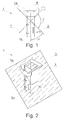
- Fig. 1 shows a partitioned transport channel 1 for gravitational transport of rod-like articles from a higher level to a lower level in the tobacco industry in the front view before the assembly.
- the channel 1 has a shape of a cube with an internal flow surface in which filter or tobacco rods are transported.
- the channel 1 is partitioned into two parts 1a and 1b by a virtual plane 2 which partitions the channel 1 transversely at an angle ⁇ in the range of 0-90°, more preferably at an angle of 30-60 degrees to the channel axis, or at a preferred angle of 45° to its X axis which centrally crosses the middle of the channel and is principally vertical.
- Our rotational movement of the part 1b made towards us when facing the front plane of the channel around the axis of rotation Y causes its deflection upwards.
- the axis Y is situated at an angle ⁇ in the range of 80-100°, preferably 90°, to the virtual plane 2 and may be parallel to the channel axis X.
- the channel 1 is kept in the assembled position ( Fig. 4 ) by the lock 7 situated at the hinge ( Fig. 3 ).
- the hinge 4 is adjacent to one of the channel walls at the level of its partition and is partitioned by a virtual plane 2 into two parts 4a and 4b at the same angle ⁇ to the channel axis X at which the channel 1 is partitioned.
- Each part of the hinge 4a and 4b is permanently fastened to the channel's upper part 1a and bottom part 1b, respectively.
- a member connecting both parts in the hinge 4 is the pin 5 through which the axis of rotation Y passes.
- the presented embodiment shows a channel in which the second part is a rotatably fastened part, and the axis of the rotatable connection is situated at the side wall of the channel.
- the axis of the rotation outside of the contour of the transport channel.
- connection of the first and the second part relies on the replacement of the rotatable connection by a slidable connection in which the second part of the channel is slidably fastened relative to the first part.
- connection Regardless of the character of the connection, that is both in case of a rotatable (rotation) and a slidable (translation) connection, favourable effects where observed in particular when the upper edges of the second part moved principally in the plane of the partition.
- connection has to ensure a relative movement of bottom edges of the second part, in particular all bottom edges of the second part of the channel, with a motion component directed principally upwards. It is so important because the outlet of the transport channel, thus the bottom edges of the second part of the channel are situated very close to the device to which the rod-like articles are delivered.
- the clearance between the channel outlet and the receiving device is usually smaller than the diameter of a rod-like article, thus the movement of the second part of the channel should be principally free from the motion component directed downwards - which allows avoiding a collision between the second part of the transport channel and the receiving device.
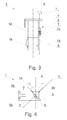
- Fig. 2 shows the partitioned transport channel 1 together with a partitioning virtual plane 2 in an axonometric view.
- the plane 2 transversely partitions the channel 1 into two parts, in this embodiment an upper immovable part 1a and a bottom movable part 1b. From the side of the inlet into the channel 1, a hatched surface of the flow 3 of rod-like articles through this channel is visible.
- Fig. 3 shows the partitioned transport channel 1 in the side view.
- a hinge 4 is fastened to the rear wall 6 of the channel 1.
- the virtual plane 2 (not shown in the drawing) transversely partitioning the channel 1 into two parts 1a and 1b also partitions the hinge 4 into two parts 4a and 4b which are fastened to the rear wall 6 of the channel 1 to the parts 1a and 1b, respectively.
- a member connecting two parts of the channel 1a and 1b and two parts of the hinge 4a and 4b is a pin 5 situated in the hinge 4, passing through its two parts 4a and 4b perpendicular to the virtual partition plane 2 (not visible in the figure).
- the axis of rotation Y which may be parallel to the axis X passes centrally along the pin 5.
- the axis of rotation Y must be situated outside of the area of flow 3 of rod-like articles in the channel 1. It can overlap the rear wall 6 of the channel 1 or it may be situated outside of its contour.
- Fig. 4 shows the front view of the channel 1 after the assembly in the final position.
- the rear wall 6b of the bottom part 1b which is situated outside of the working area of the upper part 1a ( Fig. 5 ) becomes visible, whereas the side wall 9 of the bottom part 1b reaches the level of the bottom edge 8 of the part 1a.
- the bottom part of the hinge 4b which is fastened to the bottom part of the channel 1b around the axis of rotation Y, moves along the same path.
- Fig. 5 shows the partitioned transport channel 1 after the assembly with a visible displacement of the part 1a relative to the part 1. Due to the rotational movement in the partition plane the transport channel is broken, and the channel outlet moves with a motion component directed upwards.
Landscapes
- Packaging Of Annular Or Rod-Shaped Articles, Wearing Apparel, Cassettes, Or The Like (AREA)
Abstract
The object of the application is a channel (1) for transporting rod-like articles in the tobacco industry, arranged in layers and transversely to their direction of transport, transversely partitioned into two parts, a first immovable part (1a) and a second movable part (1b), with one of them being rotatable around the channel axis (X), whereas the second part is movably fastened relative to the first part. A channel (1) according to the invention is characterized in that the plane (2) of partition of the channel into two parts extends at an angle to the channel axis, and the movable connection allows the movement of the second part of the channel relative to the first part of the channel so that during the movement the bottom edges of the second part principally move with a motion component directed upwards.
Description
- The object of the invention is a partitioned transport channel for the downward gravitational transport of rod-like articles in the tobacco industry.
- In the production lines of rod-like articles of the tobacco industry such as cigarettes, filters or cigarettes with filters already attached , in the course of the production process the said articles cover a considerable distance after leaving the manufacturing machine before being placed into packages in the packaging machine or into the storages. They are usually conveyed in a multi-layered ordered stack, which eliminates the deformation, damage or destruction of the articles. There is a need of handling the stream of articles in order to deliver it to or from different devices used in the production line, among others in the downward direction. For this purpose, on the path of a horizontal conveyor transferring the articles, generally perpendicular channels connecting one horizontal conveyor with another horizontal conveyor or receiver are created. From time to time, there is a need to replace the receiver situated under the vertical transport channel, then it is necessary to disassemble, in whole or in part, the vertical transport channel connecting this receiver with the conveyor situated at a different level in order to put away one receiver and place another one.
- The substance of the invention is a channel for the transport of rod-like articles in the tobacco industry, arranged in layers and transversely to their direction of transport, transversely partitioned into two parts, a first immovable part and a second movable part, with the second part being movably fastened relative to the first part. A channel according to the invention is characterized in that the plane of partition of the channel into two parts runs at an angle to axis of the channel, and the movable connection allows the movement of the second part of the channel relative to the first part of the channel so that during the movement the bottom edges of the second part move with a motion component directed principally upwards.
- Furthermore, a channel according to the invention is characterized in that the plane crosses the channel at an angle of 0-90 degrees to the channel axis.
- Furthermore, a channel according to the invention is characterized in that the plane crosses the channel at an angle of 30-60 degrees to the channel axis.
- Furthermore, a channel according to the invention is characterized in that the plane crosses the channel principally at an angle of 45 degrees to the channel axis.
- Furthermore, a channel according to the invention is characterized in that the second part of the channel is a rotatably fastened part, and the axis of the rotary connection is situated at a side wall of the channel.
- Furthermore, a channel according to the invention is characterized in that the second part of the channel is a slidably fastened part relative to the first part.
- Furthermore, a channel according to the invention is characterized in that the axis of rotation is situated outside of the contour of the transport channel.
- Furthermore, a channel according to the invention is characterized in that axis of rotation is situated outside of the flow area of the transport channel.
- Furthermore, the channel according to the invention is characterized in that the movable connection allows the movement of the second part of the channel relative to the first part of the channel so that during the movement the upper edges of the second part of the channel move in the partition plane.
- Furthermore, the channel according to the invention is characterized in that the movable connection allows the movement of the second part of the channel relative to the first part of the channel so that during the movement all bottom edges of the second part principally move with a motion component directed upwards.
- Due to the use of a partitioned transport channel in the mass flow of rod-like articles in the tobacco industry, we may more efficiently replace devices receiving the articles from the channel without the necessity of disassembling it. Due to the use of a rotatable hinge situated at the line of partition of the channel and outside of its cross-section contour, when we make a rotational movement of the bottom part towards us, around the hinge axis, we deflect it rotationally upwards clearing the space under the channel. Furthermore, it is not required to keep a large gap between the bottom edge of the bottom part and the upper edge of the inlet into the receiving device, which would adversely affect the flow of rod-like articles. It is required to keep a distance between the upper part and the bottom part of the channel if a pivoting hinge with the horizontal axis of rotation, parallel to the bottom edge of the channel is used. By making a rotational movement around the horizontal axis, the bottom part of the channel causes the crossing of the line on which the bottom edge of the channel is situated.
- The object of the invention was presented in detail in a preferred embodiment in a drawing in which:
- Fig. 1
- shows a partitioned transport channel in a front view before the assembly;
- Fig. 2
- shows the partitioned transport channel in an axonometric view with a plane partitioning the channel into two parts before the assembly;
- Fig. 3
- shows the partitioned transport channel in a side view before the assembly;
- Fig. 4
- shows the partitioned transport channel in a front view after the assembly;
- Fig. 5
- shows the partitioned transport channel in a side view with a visible partitioning plane after the assembly;
-
Fig. 1 shows apartitioned transport channel 1 for gravitational transport of rod-like articles from a higher level to a lower level in the tobacco industry in the front view before the assembly. Thechannel 1 has a shape of a cube with an internal flow surface in which filter or tobacco rods are transported. Thechannel 1 is partitioned into twoparts virtual plane 2 which partitions thechannel 1 transversely at an angle α in the range of 0-90°, more preferably at an angle of 30-60 degrees to the channel axis, or at a preferred angle of 45° to its X axis which centrally crosses the middle of the channel and is principally vertical. Such a channel, transversely partitioned at an angle 45° to the channel axis X, takes the least space necessary for its assembly. Our rotational movement of thepart 1b made towards us when facing the front plane of the channel around the axis of rotation Y causes its deflection upwards. The axis Y is situated at an angle β in the range of 80-100°, preferably 90°, to thevirtual plane 2 and may be parallel to the channel axis X. Thechannel 1 is kept in the assembled position (Fig. 4 ) by thelock 7 situated at the hinge (Fig. 3 ). Thehinge 4 is adjacent to one of the channel walls at the level of its partition and is partitioned by avirtual plane 2 into twoparts channel 1 is partitioned. Each part of thehinge upper part 1a andbottom part 1b, respectively. A member connecting both parts in thehinge 4 is thepin 5 through which the axis of rotation Y passes. Such a movable connection of first and second parts allows for a movement of the second part of the channel relative to the first part of the channel so that during the movement the bottom edges of the second part move with a motion component directed principally upwards. - The presented embodiment shows a channel in which the second part is a rotatably fastened part, and the axis of the rotatable connection is situated at the side wall of the channel. However, it is possible to place the axis of the rotation outside of the contour of the transport channel.
- As an alternative, the connection of the first and the second part relies on the replacement of the rotatable connection by a slidable connection in which the second part of the channel is slidably fastened relative to the first part.
- Regardless of the character of the connection, that is both in case of a rotatable (rotation) and a slidable (translation) connection, favourable effects where observed in particular when the upper edges of the second part moved principally in the plane of the partition. Regardless of the character of the connection, it has to ensure a relative movement of bottom edges of the second part, in particular all bottom edges of the second part of the channel, with a motion component directed principally upwards. It is so important because the outlet of the transport channel, thus the bottom edges of the second part of the channel are situated very close to the device to which the rod-like articles are delivered. The clearance between the channel outlet and the receiving device is usually smaller than the diameter of a rod-like article, thus the movement of the second part of the channel should be principally free from the motion component directed downwards - which allows avoiding a collision between the second part of the transport channel and the receiving device.
-
Fig. 2 shows thepartitioned transport channel 1 together with a partitioningvirtual plane 2 in an axonometric view. Theplane 2 transversely partitions thechannel 1 into two parts, in this embodiment an upperimmovable part 1a and a bottommovable part 1b. From the side of the inlet into thechannel 1, a hatched surface of theflow 3 of rod-like articles through this channel is visible. -
Fig. 3 shows thepartitioned transport channel 1 in the side view. Ahinge 4 is fastened to the rear wall 6 of thechannel 1. The virtual plane 2 (not shown in the drawing) transversely partitioning thechannel 1 into twoparts hinge 4 into twoparts channel 1 to theparts channel hinge pin 5 situated in thehinge 4, passing through its twoparts pin 5. The axis of rotation Y must be situated outside of the area offlow 3 of rod-like articles in thechannel 1. It can overlap the rear wall 6 of thechannel 1 or it may be situated outside of its contour. -
Fig. 4 shows the front view of thechannel 1 after the assembly in the final position. When me make a rotational movement relative to the axis Y through the bottom part of thechannel 1b towards us when standing opposite to the channel, in the front view therear wall 6b of thebottom part 1b which is situated outside of the working area of theupper part 1a (Fig. 5 ) becomes visible, whereas theside wall 9 of thebottom part 1b reaches the level of thebottom edge 8 of thepart 1a. The bottom part of thehinge 4b, which is fastened to the bottom part of thechannel 1b around the axis of rotation Y, moves along the same path. -
Fig. 5 shows thepartitioned transport channel 1 after the assembly with a visible displacement of thepart 1a relative to thepart 1. Due to the rotational movement in the partition plane the transport channel is broken, and the channel outlet moves with a motion component directed upwards. - The solution according to the invention was presented with reference to a channel with a principally cuboid shape, i.e. channels with a rectangular cross-section; however, it may be just as well used for oval or elliptic channels. The usefulness of the invention for all abovementioned channel shapes has been proven in carried out tests and simulations.
Claims (10)
- A channel for the transport of rod-like articles in the tobacco industry, arranged in layers and transversely to their direction of transport, transversely partitioned into two parts, first immovable part and second movable part, whereas
the second part is fastened movably relative to the first part
characterized in that
the plane (2) partitioning the channel into two parts (1a, 1b) runs at an angle to theaxis of the channel, and
the movable connection allows the movement of the second part (1b) of the channel relative to the first part (1a) of the channel so that during the movement the bottom edges of the second part (1b) move with a motion component directed principally upwards. - A channel as in claim 1 characterized in that the partition plane (2) crosses the channel at an angle of 0-90 degrees to the channel axis.
- A channel as in claim 1 characterized in that the partition plane (2) crosses the channel at an angle of 30-60 degrees to the channel axis.
- A channel as in claim 1-3 characterized in that the partition plane (2) crosses the channel principally at the angle of 45 degrees to the channel axis.
- A channel as in any of claims 1 to 4 characterized in that the second part (1b) of the channel is a rotatably fastened part, and the axis of the rotary connection is situated at a side wall of the channel.
- A channel as in any of claims 1 to 4 characterized in that the second part (1b) of the channel is fastened slidably relative to the first part.
- A channel as in claim 5 characterized in that the axis of rotation (Y) is situated outside of the contour of the transport channel.
- A channel as in any of the claims 5 or 7 characterized in that the axis of rotation (Y) is situated outside of the flow area of transport channel.
- A channel as in any of claims 1 to 8 characterized in that the movable connection allows the movement of the second part (1b) of the channel relative to the first part of the channel so that during the movement the upper edges of the second part of the channel move in the partition plane.
- A channel as in any of claims 1 to 9 characterized in that the movable connection allows the movement of the second part (1b) of the channel relative to the first part (1a) of the channel so that during the movement all bottom edges of the second part principally move with a motion component directed upwards.
Priority Applications (1)
| Application Number | Priority Date | Filing Date | Title |
|---|---|---|---|
| EP14195446.1A EP3025596A1 (en) | 2014-11-28 | 2014-11-28 | A splittable transport channel used in the tobacco-processing industry |
Applications Claiming Priority (1)
| Application Number | Priority Date | Filing Date | Title |
|---|---|---|---|
| EP14195446.1A EP3025596A1 (en) | 2014-11-28 | 2014-11-28 | A splittable transport channel used in the tobacco-processing industry |
Publications (1)
| Publication Number | Publication Date |
|---|---|
| EP3025596A1 true EP3025596A1 (en) | 2016-06-01 |
Family
ID=52347073
Family Applications (1)
| Application Number | Title | Priority Date | Filing Date |
|---|---|---|---|
| EP14195446.1A Withdrawn EP3025596A1 (en) | 2014-11-28 | 2014-11-28 | A splittable transport channel used in the tobacco-processing industry |
Country Status (1)
| Country | Link |
|---|---|
| EP (1) | EP3025596A1 (en) |
Citations (5)
| Publication number | Priority date | Publication date | Assignee | Title |
|---|---|---|---|---|
| US3348646A (en) * | 1966-05-03 | 1967-10-24 | Mccall Leonard | Truck unloading chute |
| US3595356A (en) * | 1969-05-05 | 1971-07-27 | Compactor Corp | Adjustable chute and access door |
| EP0201847A2 (en) * | 1985-05-14 | 1986-11-20 | Albert Böcker GmbH & Co. KG | A plurality of telescopic chute elements forming a transfer chute |
| WO2002096227A2 (en) * | 2001-05-25 | 2002-12-05 | International Tobacco Machinery Poland Ltd. | Method of separating streams of displacing multi-layered stacks of rodlike elements and valve device for separating streams of multi-layered stacks of rodlike elements |
| WO2011099880A1 (en) * | 2010-02-10 | 2011-08-18 | International Tobacco Machinery Poland Sp. Z.O.O. | Method of mass flow control and device for mass flow control |
-
2014
- 2014-11-28 EP EP14195446.1A patent/EP3025596A1/en not_active Withdrawn
Patent Citations (5)
| Publication number | Priority date | Publication date | Assignee | Title |
|---|---|---|---|---|
| US3348646A (en) * | 1966-05-03 | 1967-10-24 | Mccall Leonard | Truck unloading chute |
| US3595356A (en) * | 1969-05-05 | 1971-07-27 | Compactor Corp | Adjustable chute and access door |
| EP0201847A2 (en) * | 1985-05-14 | 1986-11-20 | Albert Böcker GmbH & Co. KG | A plurality of telescopic chute elements forming a transfer chute |
| WO2002096227A2 (en) * | 2001-05-25 | 2002-12-05 | International Tobacco Machinery Poland Ltd. | Method of separating streams of displacing multi-layered stacks of rodlike elements and valve device for separating streams of multi-layered stacks of rodlike elements |
| WO2011099880A1 (en) * | 2010-02-10 | 2011-08-18 | International Tobacco Machinery Poland Sp. Z.O.O. | Method of mass flow control and device for mass flow control |
Similar Documents
| Publication | Publication Date | Title |
|---|---|---|
| JP6082000B2 (en) | Packaging machine and method for producing a rigid packet each comprising at least two containers, one container inside another container | |
| PL236145B1 (en) | Valve device for switching the mass flow of bar-like assortment in the tobacco industry transport channels | |
| ES2478548T3 (en) | Container filling apparatus for filling containers with pharmaceutical / parapharmaceutical items | |
| US10820600B2 (en) | Device and method for transferring sausage portions | |
| CN103813727B (en) | Material for filling rod shaped article flows to the valve cell of dihedral transfer passage | |
| RU2519896C2 (en) | Method of controlling mass flow and apparatus for controlling mass flow | |
| JP4015028B2 (en) | Method for separating the flow of a multilayer stack of moving rod-like elements and valve device for separating the flow of a multilayer stack of rod-like elements | |
| EP2676884B1 (en) | Apparatus for feeding rod-shaped articles in a packaging machine | |
| RU2020100242A (en) | FORMING AND TRANSPORTING DEVICE FOR MOVING AND FORMING A GROUP OF ROD-SHAPED PRODUCTS AND FEEDING DEVICE FOR FEEDING A GROUP OF ROD-SHAPED PRODUCTS | |
| EP2995207A1 (en) | Transport system | |
| JP6670168B2 (en) | Article transfer equipment | |
| BR102016008638B1 (en) | DEVICE FOR SUPPORTING A MASS FLOW OF ROD-SHAPED ARTICLES FROM THE TOBACCO INDUSTRY INTO A TRANSPORT CHANNEL AND METHOD OF FILLING AND EMPTYING THE TRANSPORT CHANNEL | |
| KR101409020B1 (en) | Apparatus for aligning and supplying articles | |
| JP6578606B2 (en) | Cleaning system for transport and storage devices with adjustable capacity for multiple rod-like elements in the tobacco industry | |
| CN108135252A (en) | Centering device for rod products in the tobacco industry | |
| JPWO2021070302A5 (en) | ||
| HRP20191890T1 (en) | Method and device for positioning portion packets | |
| PL227990B1 (en) | Sectional transport channel in tobacco industry | |
| JP6475144B2 (en) | Boxing equipment | |
| JP2017088183A (en) | Boxing equipment | |
| NL2013023B1 (en) | Modular conveyor belt comprising a plurality of modular belt links, modular belt link configured for use in such a modular conveyor belt and molding method for manufacturing such a modular belt link. | |
| ES2612434T3 (en) | System and related procedure for classifying a plurality of pillow-type bags containing salted products | |
| CN204384491U (en) | Article carrying apparatus | |
| IT202100010202A1 (en) | EQUIPMENT FOR COUNTING AND UNLOADING PHARMACEUTICAL ITEMS | |
| ITMI20111351A1 (en) | OBJECT ORIENTATION DEVICE |
Legal Events
| Date | Code | Title | Description |
|---|---|---|---|
| PUAI | Public reference made under article 153(3) epc to a published international application that has entered the european phase |
Free format text: ORIGINAL CODE: 0009012 |
|
| AK | Designated contracting states |
Kind code of ref document: A1 Designated state(s): AL AT BE BG CH CY CZ DE DK EE ES FI FR GB GR HR HU IE IS IT LI LT LU LV MC MK MT NL NO PL PT RO RS SE SI SK SM TR |
|
| AX | Request for extension of the european patent |
Extension state: BA ME |
|
| STAA | Information on the status of an ep patent application or granted ep patent |
Free format text: STATUS: THE APPLICATION IS DEEMED TO BE WITHDRAWN |
|
| 18D | Application deemed to be withdrawn |
Effective date: 20161202 |