EP3025418B1 - Kühlvorrichtung für eine elektrische maschine - Google Patents
Kühlvorrichtung für eine elektrische maschine Download PDFInfo
- Publication number
- EP3025418B1 EP3025418B1 EP14758909.7A EP14758909A EP3025418B1 EP 3025418 B1 EP3025418 B1 EP 3025418B1 EP 14758909 A EP14758909 A EP 14758909A EP 3025418 B1 EP3025418 B1 EP 3025418B1
- Authority
- EP
- European Patent Office
- Prior art keywords
- capillary
- cooling fluid
- laminated core
- electrical machine
- cooling
- Prior art date
- Legal status (The legal status is an assumption and is not a legal conclusion. Google has not performed a legal analysis and makes no representation as to the accuracy of the status listed.)
- Not-in-force
Links
- 238000001816 cooling Methods 0.000 title claims description 32
- 239000012809 cooling fluid Substances 0.000 claims description 45
- 239000007788 liquid Substances 0.000 claims description 20
- 239000004020 conductor Substances 0.000 claims description 11
- 238000001704 evaporation Methods 0.000 claims description 8
- 230000008020 evaporation Effects 0.000 claims description 8
- LFQSCWFLJHTTHZ-UHFFFAOYSA-N Ethanol Chemical compound CCO LFQSCWFLJHTTHZ-UHFFFAOYSA-N 0.000 claims description 6
- OKKJLVBELUTLKV-UHFFFAOYSA-N Methanol Chemical compound OC OKKJLVBELUTLKV-UHFFFAOYSA-N 0.000 claims description 6
- VLKZOEOYAKHREP-UHFFFAOYSA-N n-Hexane Chemical compound CCCCCC VLKZOEOYAKHREP-UHFFFAOYSA-N 0.000 claims description 6
- OFBQJSOFQDEBGM-UHFFFAOYSA-N n-pentane Natural products CCCCC OFBQJSOFQDEBGM-UHFFFAOYSA-N 0.000 claims description 6
- XLYOFNOQVPJJNP-UHFFFAOYSA-N water Substances O XLYOFNOQVPJJNP-UHFFFAOYSA-N 0.000 claims description 6
- LRHPLDYGYMQRHN-UHFFFAOYSA-N N-Butanol Chemical compound CCCCO LRHPLDYGYMQRHN-UHFFFAOYSA-N 0.000 claims description 4
- IMNFDUFMRHMDMM-UHFFFAOYSA-N N-Heptane Chemical compound CCCCCCC IMNFDUFMRHMDMM-UHFFFAOYSA-N 0.000 claims description 4
- ATUOYWHBWRKTHZ-UHFFFAOYSA-N Propane Chemical compound CCC ATUOYWHBWRKTHZ-UHFFFAOYSA-N 0.000 claims description 4
- 150000001335 aliphatic alkanes Chemical class 0.000 claims description 2
- 239000001273 butane Substances 0.000 claims description 2
- 239000000463 material Substances 0.000 claims description 2
- IJDNQMDRQITEOD-UHFFFAOYSA-N n-butane Chemical compound CCCC IJDNQMDRQITEOD-UHFFFAOYSA-N 0.000 claims description 2
- BDERNNFJNOPAEC-UHFFFAOYSA-N propan-1-ol Chemical compound CCCO BDERNNFJNOPAEC-UHFFFAOYSA-N 0.000 claims description 2
- 239000001294 propane Substances 0.000 claims description 2
- 238000009413 insulation Methods 0.000 description 5
- 238000009833 condensation Methods 0.000 description 4
- 230000005494 condensation Effects 0.000 description 4
- 230000004907 flux Effects 0.000 description 4
- 238000010586 diagram Methods 0.000 description 3
- 108020005351 Isochores Proteins 0.000 description 2
- 239000007789 gas Substances 0.000 description 2
- 230000005484 gravity Effects 0.000 description 2
- 150000001298 alcohols Chemical class 0.000 description 1
- 230000015556 catabolic process Effects 0.000 description 1
- 239000000110 cooling liquid Substances 0.000 description 1
- 238000000354 decomposition reaction Methods 0.000 description 1
- 230000000694 effects Effects 0.000 description 1
- 239000012530 fluid Substances 0.000 description 1
- 239000001257 hydrogen Substances 0.000 description 1
- 229910052739 hydrogen Inorganic materials 0.000 description 1
- 125000004435 hydrogen atom Chemical class [H]* 0.000 description 1
- 230000000750 progressive effect Effects 0.000 description 1
- 238000004904 shortening Methods 0.000 description 1
- 239000000126 substance Substances 0.000 description 1
- 238000005979 thermal decomposition reaction Methods 0.000 description 1
- 238000009834 vaporization Methods 0.000 description 1
- 230000008016 vaporization Effects 0.000 description 1
- 238000004804 winding Methods 0.000 description 1
Images

Classifications
-
- F—MECHANICAL ENGINEERING; LIGHTING; HEATING; WEAPONS; BLASTING
- F28—HEAT EXCHANGE IN GENERAL
- F28D—HEAT-EXCHANGE APPARATUS, NOT PROVIDED FOR IN ANOTHER SUBCLASS, IN WHICH THE HEAT-EXCHANGE MEDIA DO NOT COME INTO DIRECT CONTACT
- F28D15/00—Heat-exchange apparatus with the intermediate heat-transfer medium in closed tubes passing into or through the conduit walls ; Heat-exchange apparatus employing intermediate heat-transfer medium or bodies
- F28D15/02—Heat-exchange apparatus with the intermediate heat-transfer medium in closed tubes passing into or through the conduit walls ; Heat-exchange apparatus employing intermediate heat-transfer medium or bodies in which the medium condenses and evaporates, e.g. heat pipes
-
- F—MECHANICAL ENGINEERING; LIGHTING; HEATING; WEAPONS; BLASTING
- F28—HEAT EXCHANGE IN GENERAL
- F28D—HEAT-EXCHANGE APPARATUS, NOT PROVIDED FOR IN ANOTHER SUBCLASS, IN WHICH THE HEAT-EXCHANGE MEDIA DO NOT COME INTO DIRECT CONTACT
- F28D15/00—Heat-exchange apparatus with the intermediate heat-transfer medium in closed tubes passing into or through the conduit walls ; Heat-exchange apparatus employing intermediate heat-transfer medium or bodies
- F28D15/02—Heat-exchange apparatus with the intermediate heat-transfer medium in closed tubes passing into or through the conduit walls ; Heat-exchange apparatus employing intermediate heat-transfer medium or bodies in which the medium condenses and evaporates, e.g. heat pipes
- F28D15/0275—Arrangements for coupling heat-pipes together or with other structures, e.g. with base blocks; Heat pipe cores
-
- F—MECHANICAL ENGINEERING; LIGHTING; HEATING; WEAPONS; BLASTING
- F28—HEAT EXCHANGE IN GENERAL
- F28D—HEAT-EXCHANGE APPARATUS, NOT PROVIDED FOR IN ANOTHER SUBCLASS, IN WHICH THE HEAT-EXCHANGE MEDIA DO NOT COME INTO DIRECT CONTACT
- F28D15/00—Heat-exchange apparatus with the intermediate heat-transfer medium in closed tubes passing into or through the conduit walls ; Heat-exchange apparatus employing intermediate heat-transfer medium or bodies
- F28D15/02—Heat-exchange apparatus with the intermediate heat-transfer medium in closed tubes passing into or through the conduit walls ; Heat-exchange apparatus employing intermediate heat-transfer medium or bodies in which the medium condenses and evaporates, e.g. heat pipes
- F28D15/0283—Means for filling or sealing heat pipes
-
- H—ELECTRICITY
- H02—GENERATION; CONVERSION OR DISTRIBUTION OF ELECTRIC POWER
- H02K—DYNAMO-ELECTRIC MACHINES
- H02K9/00—Arrangements for cooling or ventilating
- H02K9/22—Arrangements for cooling or ventilating by solid heat conducting material embedded in, or arranged in contact with, the stator or rotor, e.g. heat bridges
- H02K9/225—Heat pipes
Definitions
- the invention relates to a cooling device for an electric machine and an electric machine with the cooling device.
- an electric machine such as a motor or a generator
- electrical energy is converted into rotational energy or rotational energy into electrical energy.
- the electric machine has a rotor and a stator, wherein the stator has a laminated core in which electrical conductors are inserted and designed as a winding.
- the electrical conductors are surrounded by a main insulation.
- the conductors heat up due to the electrical currents flowing in them. By heat conduction, the heat released in the conductors is also transferred to the main insulation and the laminated core.
- cooling ducts are conventionally provided in the laminated core, through which during operation of the electrical machine, a gas, such as air or hydrogen, is flowed to cool the laminated core.
- a gas such as air or hydrogen
- EP2 509 196A1 discloses a generic electrical machine.
- the object of the invention is to provide an electric machine with cooling device, wherein with the cooling device high heat flux densities can be dissipated from the laminated core.
- the inventive electric machine with cooling device has at least one closed capillary, within which a cooling fluid is located and which is introduced into a recess of a laminated core of the electric machine such that the capillary is thermally conductively connected to the laminated core and partially protruding from the laminated core, so in that the capillary has a cold end arranged outside the laminated core and a warm end arranged inside the laminated core, the cooling fluid, the degree of filling of the capillary with the cooling fluid and in particular the thermodynamic state point of the cooling fluid being selected such that an entry occurs during operation of the electrical machine heat from the laminated core into the capillary leads to evaporation of the cooling fluid and the cold end of the capillary is coolable such that the vapor formed during the evaporation condenses and discharges the heat introduced into the capillary from the capillary rbar is.
- the degree of filling of the capillary with the cooling fluid is selected according to the invention such that the molar volume of the cooling fluid in the capillary is essentially the critical molar volume.
- the cooling fluid over the widest possible pressure range is both liquid and gaseous, so that the cooling device in the widest possible pressure range works.
- the evaporation enthalpy and the condensation enthalpy of the cooling fluid are utilized. This is compared to a conventional cooling, in which the heat is transferred to a gas, the heat with a much higher heat flux density from the laminated core can be discharged. As a result, the electric machine can be operated at a higher power for a given length of the laminated core. It is also possible to make the laminated core shorter for a given power of the electric machine. It is also possible to retrofit an existing electrical machine with the cooling device according to the invention, so that the existing electric machine can be operated at a higher power.
- the cooling fluid and the material of the capillary be selected such that the adhesion between the capillary and the cooling fluid is greater than the cohesion of the cooling fluid, and the capillary is formed so thin that in the operation of the electric machine regardless of an influence of gravity forms a circulation flow of the cooling fluid in the capillary, wherein the circulation flow is such that forms on the inside of the capillary, a film of liquid, which moves substantially from the cold end to the warm end, and encased by The film essentially moves the steam from the warm end to the cold end.
- This advantageously ensures that the circulation flow is independent of the orientation of the capillary.
- the cold end can be arranged above, below or in a same horizontal plane of the warm end.
- the circulation flow has advantageously a high mass flow, whereby the heat flow density with which the heat is discharged from the laminated core is high.
- the inner diameter of the capillary is preferably from 1 mm to 5 mm. For smaller diameters, it is not possible for both a phase of the liquid and a phase of the vapor to be present simultaneously in a cross-section of the capillary. With a larger diameter, the capillary effect is insufficient, that with a vertical orientation of the capillary, in which the cold end below the warm end is arranged, the liquid moves against gravity upwards.
- the cooling device preferably has a liquid cooling, in particular a water cooling, by means of which the cold end of the capillary is coolable. It is preferred that the cooling device has a cooling rib, by means of which the cold end of the capillary can be cooled. It is preferred that the cooling fins are gas-cooled.
- the laminated core has juxtaposed grooves in the circumferential direction into which electrical conductors are inserted, and the warm end of the capillary is arranged between two adjacent grooves. Because the heat to be dissipated from the laminated core is released especially in the electrical conductors, the area between two adjacent grooves is the hottest of the laminated core. By arranging the warm end of the capillary in this region, advantageously the hottest region of the laminated core can be cooled with the cooling device according to the invention.
- the cooling fluid is preferably water, an alcohol, in particular methanol, ethanol, propanol and / or butanol, and / or an alkane, in particular propane, butane, pentane, hexane and / or heptane.
- the substances mentioned are advantageous because they have a large two-phase area, which means that they are both liquid and gaseous over a wide pressure range and temperature range.
- Water and the alcohols are particularly advantageous because they have a large evaporation enthalpy. It is true that with larger evaporation enthalpies, the heat from the laminated core with higher heat flux densities can be dissipated.
- a plurality of capillaries is provided, which are provided uniformly over the circumference and distributed in the axial direction over the laminated core. This is advantageously achieved that the entire laminated core is evenly cooled.
- the electric machine according to the invention has the cooling device according to the invention. It is preferable that the electric machine is an electric generator. Alternatively, it is preferable that the electric machine is an electric motor.
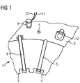
- an electric machine has an annular laminated core 1, wherein in FIG. 1 only a section of the laminated core 1 is shown.
- On the radial inner side 3 of the laminated core 1 are juxtaposed in the circumferential direction and substantially axially extending grooves 4 are introduced.
- electrical conductors are introduced, wherein the electrical conductors are surrounded by a main insulation, so that the electrical conductors are electrically insulated from the laminated core 1.
- recesses 5 are arranged, which extend from a region between two adjacent grooves 4 to the radial outer side 2 of the laminated core 1.
- a capillary 6 is introduced in each case.
- the capillaries 6 are thermally conductive contacted with the laminated core 1.
- a thermal paste may be introduced between the laminated core 1 and the capillary 6.
- the capillary 6 has a cylindrical tube whose two ends are closed, so that the capillary 6 is closed in such a way that no fluid can enter or exit the capillary 6.
- the capillary 6 is longer than the recess 5, so that it has introduced into the recess 5 a cold end 8, which is arranged outside the laminated core 1, and has a warm end 7, which is arranged within the laminated core 1.
- the warm end 7 is arranged between two adjacent grooves 4.
- the cold end 8 is coolable, in FIG. 1 two different embodiments of the cooling are shown.
- the cold end 8 is encased by a cap 9, to which a cooling fluid supply line 10 and a cooling fluid discharge line 11 are connected.
- a cooling liquid in particular water, is introduced via the cooling fluid supply line 10 into the cap 9, where the cooling fluid absorbs heat from the capillary 6.
- the heated in the cap 9 liquid is discharged via the cooling fluid discharge 11 from the cap 9.
- the cold end 8 is encased by a cooling fin 12.
- the cooling fin 12 can be cooled, for example, by means of an air flow.
- the capillary 6 is filled with a cooling fluid, which forms a circulation flow of the cooling fluid within the capillary during operation of the electric machine.
- the cooling fluid and the degree of filling of the capillary 6 with the cooling fluid must be selected such that during operation of the electric machine the cooling fluid is present both as a liquid 13 and as a vapor 14 at the same time. Due to the capillary action, the liquid 13 abuts against the inner side 20 of the capillary 6. The liquid 13 thus forms a substantially cylindrical ring.
- the steam 14 is inside This cylindrical ring, whereby a substantially cylindrical phase boundary 15 between the liquid 13 and the steam 14 is formed.
- the capillary action replaces evaporated liquid with inflowing liquid, resulting in a flow direction 16 of the liquid from the cold end 8 to the warm end 7.
- the steam 14 is condensed at the cold end 8, resulting in a flow direction 16 of the steam 14 from the hot end 7 to the cold end 8.
- a heat removal 18 takes place from the capillary 6.
- FIG. 3 is a p V Diagram of the cooling fluid shown. Plotted on the abscissa 22 is the molar volume V the cooling fluid and above the ordinate 23 the pressure p of the cooling fluid. Hatched in Fig. 3 is a two-phase region 24 within which the cooling fluid is present as both liquid 13 and vapor 14. At smaller molar volumes relative to the two-phase region 24, the cooling fluid is present as the liquid 13, and for larger molar volumes relative to the two-phase region 24, the cooling fluid is present as vapor 14. The maximum of the two-phase region 24 is the critical point 25.
- the cooling fluid In order for vaporization and condensation of the cooling fluid to take place, the cooling fluid must be within the two-phase region during operation of the electrical machine.
- the degree of filling is therefore to be chosen such that in addition a in the p V Diagram shows vertically extending isochores, which intersects the two-phase region 24. It is preferable to select the critical isochores which intersect the critical point 25 so that the cooling fluid is present over the widest possible pressure range in the two-phase region 24.
Landscapes
- Engineering & Computer Science (AREA)
- Life Sciences & Earth Sciences (AREA)
- Sustainable Development (AREA)
- Physics & Mathematics (AREA)
- Thermal Sciences (AREA)
- Mechanical Engineering (AREA)
- General Engineering & Computer Science (AREA)
- Power Engineering (AREA)
- Motor Or Generator Cooling System (AREA)
Description
- Die Erfindung betrifft eine Kühlvorrichtung für eine elektrische Maschine und eine elektrische Maschine mit der Kühlvorrichtung.
- In einer elektrischen Maschine, wie beispielsweise ein Motor oder ein Generator, wird elektrische Energie in Rotationsenergie beziehungsweise Rotationsenergie in elektrische Energie umgewandelt. Die elektrische Maschine weist einen Rotor und einen Stator auf, wobei der Stator ein Blechpaket aufweist, in dem elektrische Leiter eingelegt sind und als Wicklung ausgeführt sind. Um die Leiter gegeneinander, gegen die Umgebung und gegen das Blechpaket elektrisch zu isolieren, sind die elektrischen Leiter von einer Hauptisolation umhüllt. Im Betrieb der elektrischen Maschine heizen sich die Leiter aufgrund der in ihnen fließenden elektrischen Ströme auf. Durch Wärmeleitung wird die in den Leitern freigesetzte Wärme auch auf die Hauptisolation und das Blechpaket übertragen.
- Weil nach einem Überschreiten einer maximal zulässigen Temperatur eine thermische Zersetzung der Hauptisolation eintritt, ist eine Begrenzung der Temperatur der elektrischen Maschine auf die maximal zulässige Temperatur erforderlich. Nach einer fortschreitenden Zersetzung kann es zu einem elektrischen Durchschlag durch die Hauptisolation kommen, was zu einer Verkürzung der Lebensdauer der elektrischen Maschine führt. Um das Überschreiten der maximal zulässigen Temperatur zu unterbinden, werden herkömmlich in dem Blechpaket Kühlkanäle vorgesehen, durch die im Betrieb der elektrischen Maschine ein Gas, wie beispielsweise Luft oder Wasserstoff, geströmt wird, um das Blechpaket zu kühlen. Es ist jedoch nachteilig, dass damit Wärme nur mit geringen Wärmestromdichten aus dem Blechpaket abgeführt werden kann. Die maximale Leistung, mit der die elektrische Maschine betreibbar ist, ist begrenzt durch die aus dem Blechpaket abführbare Wärme.
-
EP2 509 196A1 offenbart eine gattungsgemäße elektrische Maschine. - Aufgabe der Erfindung ist es, eine elektrische Maschine mit Kühlvorrichtung zu schaffen, wobei mit der Kühlvorrichtung hohe Wärmestromdichten aus dem Blechpaket abführbar sind.
- Die erfindungsgemässe elektrische Maschine mit Kühlvorrichtung weist mindestens eine abgeschlossene Kapillare auf, innerhalb derer ein Kühlfluid sich befindet und die in eine Aussparung eines Blechpakets der elektrischen Maschine derart eingebracht ist, dass die Kapillare wärmeleitend mit dem Blechpaket verbunden ist und teilweise aus dem Blechpaket herausragt, so dass die Kapillare ein außerhalb des Blechpakets angeordnetes kaltes Ende und ein innerhalb des Blechpakets angeordnetes warmes Ende aufweist, wobei das Kühlfluid, der Füllgrad der Kapillare mit dem Kühlfluid und insbesondere der thermodynamische Zustandspunkt des Kühlfluids derart gewählt ist, dass im Betrieb der elektrischen Maschine ein Eintrag von Wärme von dem Blechpaket in die Kapillare zu einer Verdampfung des Kühlfluids führt und das kalte Ende der Kapillare derart kühlbar ist, dass der bei der Verdampfung entstehende Dampf kondensiert und die in die Kapillare eingetragene Wärme aus der Kapillare abführbar ist.
- Der Füllgrad der Kapillare mit dem Kühlfluid ist erfindungsgemäß derart gewählt, dass das molare Volumen des Kühlfluids in der Kapillare im Wesentlichen das kritische molare Volumen ist. Damit liegt das Kühlfluid über den breitestmöglichen Druckbereich sowohl flüssig als auch gasförmig vor, so dass auch die Kühlvorrichtung in dem breitest möglichen Druckbereich funktioniert.
- Beim Abführen der Wärme aus dem Blechpaket mittels der erfindungsgemäßen Kühlvorrichtung werden die Verdampfungsenthalphie und die Kondensationsenthalphie des Kühlfluids ausgenutzt. Dadurch ist im Vergleich zu einer herkömmlichen Kühlung, bei der die Wärme auf ein Gas übertragen wird, die Wärme mit einer wesentlich höheren Wärmestromdichte aus dem Blechpaket abführbar. Dadurch kann bei einer gegebenen Länge des Blechpakets die elektrische Maschine mit einer höheren Leistung betrieben werden. Es ist auch möglich, bei einer gegebenen Leistung der elektrischen Maschine das Blechpaket kürzer auszuführen. Auch ist es möglich eine bestehende elektrische Maschine mit der erfindungsgemäßen Kühlvorrichtung nachzurüsten, so dass die bestehende elektrische Maschine mit einer höheren Leistung betrieben werden kann.
- Es ist bevorzugt, dass das Kühlfluid und das Material der Kapillare derart gewählt sind, dass die Adhäsion zwischen der Kapillare und dem Kühlfluid größer als die Kohäsion des Kühlfluids ist, sowie die Kapillare derart dünn ausgebildet ist, dass sich im Betrieb der elektrischen Maschine unabhängig von einem Einfluss der Schwerkraft eine Zirkulationsströmung des Kühlfluids in der Kapillare ausbildet, wobei die Zirkulationsströmung derart ausgebildet ist, dass sich an der Innenseite der Kapillare ein Film aus Flüssigkeit bildet, die sich im Wesentlichen von dem kalten Ende zu dem warmen Ende bewegt, und ummantelt von dem Film der Dampf sich im Wesentlichen von dem warmen Ende zu dem kalten Ende bewegt. Dadurch ist vorteilhaft sichergestellt, dass sich die Zirkulationsströmung unabhängig von der Orientierung der Kapillare einstellt. So kann das kalte Ende oberhalb, unterhalb oder in einer gleichen horizontalen Ebene des warmen Endes angeordnet sein. Die Zirkulationsströmung hat vorteilhaft einen hohen Massenstrom, wodurch auch die Wärmestromdichte, mit der die Wärme aus dem Blechpaket abführbar ist, hoch ist.
- Der Innendurchmesser der Kapillare beträgt bevorzugt von 1 mm bis 5 mm. Bei kleineren Durchmessern ist es nicht möglich, dass in einem Querschnitt der Kapillare sowohl eine Phase aus der Flüssigkeit als auch eine Phase aus dem Dampf gleichzeitig vorliegen. Bei einem größeren Durchmesser reicht die Kapillarwirkung nicht aus, dass bei einer vertikalen Orientierung der Kapillare, bei der das kalte Ende unterhalb des warmen Endes angeordnet ist, die Flüssigkeit sich entgegen der Schwerkraft nach oben bewegt.
- Die Kühlvorrichtung weist bevorzugt eine Flüssigkeitskühlung auf, insbesondere eine Wasserkühlung, mittels der das Kalte Ende der Kapillare kühlbar ist. Es ist bevorzugt, dass die Kühlvorrichtung eine Kühlrippe aufweist, mittels der das kalte Ende der Kapillare kühlbar ist. Dabei ist bevorzugt, dass die Kühlrippen gasgekühlt sind. Mittels der Flüssigkeitskühlung und/oder Kühlrippe ist vorteilhaft sichergestellt, dass der Dampf im Bereich des kalten Endes kondensiert und die bei der Kondensation freigesetzte Kondensationsenthalphie aus der Kapillare abgeführt wird.
- Bevorzugtermaßen weist das Blechpaket in Umfangsrichtung nebeneinander angeordnete Nuten auf, in die elektrische Leiter eingebracht sind, und das warme Ende der Kapillare ist zwischen zwei benachbarten Nuten angeordnet. Weil die aus dem Blechpaket abzuführende Wärme insbesondere in den elektrischen Leitern freigesetzt wird, ist der Bereich zwischen zwei benachbarten Nuten der heißeste des Blechpakets. Indem das warme Ende der Kapillare in diesem Bereich angeordnet ist, ist vorteilhaft der heißeste Bereich des Blechpakets mit der erfindungsgemäßen Kühlvorrichtung kühlbar.
- Das Kühlfluid ist bevorzugt Wasser, ein Alkohol, insbesondere Methanol, Ethanol, Propanol und/oder Butanol, und/oder ein Alkan, insbesondere Propan, Butan, Pentan, Hexan und/oder Heptan. Die genannten Substanzen sind vorteilhaft, da sie über ein großes Zweiphasengebiet verfügen, was bedeutet, dass sie über einen großen Druckbereich und Temperaturbereich sowohl flüssig als auch gasförmig vorliegen. Wasser und die Alkohole sind besonders vorteilhaft, weil sie eine große Verdampfungsenthalphie haben. Dabei gilt, dass mit größeren Verdampfungsenthalphien die Wärme aus dem Blechpaket mit größeren Wärmestromdichten abführbar ist.
- Es ist bevorzugt, dass eine Mehrzahl an Kapillaren vorgesehen ist, die gleichmäßig über den Umfang und in Axialrichtung verteilt über das Blechpaket vorgesehen sind. Damit ist vorteilhaft erreicht, dass das gesamte Blechpaket gleichmäßig kühlbar ist.
- Die erfindungsgemäße elektrische Maschine weist die erfindungsgemäße Kühlvorrichtung auf. Es ist bevorzugt, dass die elektrische Maschine ein elektrischer Generator ist. Alternativ ist bevorzugt, dass die elektrische Maschine ein elektrischer Motor ist.
- Im Folgenden wird anhand der beigefügten schematischen Zeichnungen die Erfindung näher erläutert. Es zeigen:
- Figur 1
- eine Ansicht eines Blechpakets mit einer Kühlvorrichtung,
- Figur 2
- einen Schnitt durch eine Kapillare und
- Figur 3
- ein p
V -Diagramm eines Kühlfluids. - Wie es aus
Figur 1 ersichtlich ist, weist eine elektrische Maschine ein ringförmiges Blechpaket 1 auf, wobei inFigur 1 lediglich ein Ausschnitt des Blechpakets 1 dargestellt ist. An der radialen Innenseite 3 des Blechpakets 1 sind in Umfangsrichtung nebeneinander liegend und sich im Wesentlichen axial erstreckende Nuten 4 eingebracht. In die Nuten 4 sind elektrische Leiter eingebracht, wobei die elektrischen Leiter von einer Hauptisolation umhüllt sind, so dass die elektrischen Leiter gegen das Blechpaket 1 elektrisch isoliert sind. In das Blechpaket 1 sind Aussparungen 5 angeordnet, die sich von einem Bereich zwischen zwei benachbarten Nuten 4 bis zu der radialen Außenseite 2 des Blechpakets 1 erstrecken. - In jede der Aussparungen 5 ist jeweils eine Kapillare 6 eingebracht. Die Kapillaren 6 sind dabei wärmeleitend mit dem Blechpaket 1 kontaktiert. Um die Wärmeleitfähigkeit zu erhöhen kann beispielsweise zwischen dem Blechpaket 1 und der Kapillare 6 eine Wärmeleitpaste eingebracht sein. Wie es aus
Fig. 2 hervorgeht, weist die Kapillare 6 ein zylinderförmiges Rohr auf, dessen beiden Enden geschlossen sind, so dass die Kapillare 6 derart abgeschlossen ist, dass kein Fluid in die Kapillare 6 eintreten oder austreten kann. Die Kapillare 6 ist länger als die Aussparung 5, so dass sie eingebracht in die Aussparung 5 ein kaltes Ende 8 aufweist, welches außerhalb des Blechpakets 1 angeordnet ist, und ein warmes Ende 7 aufweist, welches innerhalb des Blechpakets 1 angeordnet ist. Das warme Ende 7 ist dabei zwischen zwei benachbarten Nuten 4 angeordnet. - Im Betrieb der elektrischen Maschine ist das kalte Ende 8 kühlbar, wobei in
Figur 1 zwei verschiedene Ausführungsformen der Kühlung dargestellt sind. In einer ersten Ausführungsform ist das kalte Ende 8 von einer Kappe 9 ummantelt, an die eine Kühlfluidzuleitung 10 und eine Kühlfluidableitung 11 angeschlossen ist. Eine Kühlflüssigkeit, insbesondere Wasser, wird via die Kühlfluidzuleitung 10 in die Kappe 9 eingeleitet, wo das Kühlfluid Wärme von der Kapillare 6 aufnimmt. Die in der Kappe 9 aufgewärmte Flüssigkeit wird via die Kühlfluidableitung 11 aus der Kappe 9 abgeleitet. In einer zweiten Ausführungsform ist das kalte Ende 8 von einer Kühlrippe 12 ummantelt. Die Kühlrippe 12 kann beispielsweise mittels einer Luftströmung gekühlt werden. - Wie es aus
Figur 2 ersichtlich ist, ist die Kapillare 6 mit einem Kühlfluid gefüllt, wobei sich im Betrieb der elektrischen Maschine eine Zirkulationsströmung des Kühlfluids innerhalb der Kapillare ausbildet. Dazu müssen das Kühlfluid und der Füllgrad der Kapillare 6 mit dem Kühlfluid derart gewählt werden, dass im Betrieb der elektrischen Maschine das Kühlfluid gleichzeitig sowohl als eine Flüssigkeit 13 als auch als ein Dampf 14 vorliegt. Durch die Kapillarwirkung liegt die Flüssigkeit 13 an der Innenseite 20 der Kapillare 6 an. Die Flüssigkeit 13 bildet somit einen im Wesentlichen zylinderförmigen Ring. Der Dampf 14 befindet sich im Inneren dieses zylinderförmigen Rings, wodurch eine im Wesentlichen zylinderförmige Phasengrenze 15 zwischen der Flüssigkeit 13 und dem Dampf 14 ausgebildet wird. Ein Wärmeeintrag 17 von dem Blechpaket 1 in die Kapillare 6 führt zu einer Verdampfung der Flüssigkeit 13. Durch die Kapillarwirkung wird verdampfte Flüssigkeit durch nachströmende Flüssigkeit ersetzt, wodurch sich eine Strömungsrichtung 16 der Flüssigkeit von dem kalten Ende 8 zu dem warmen Ende 7 ergibt. Der Dampf 14 wird an dem kalten Ende 8 kondensiert, wodurch sich eine Strömungsrichtung 16 des Dampfs 14 von dem warmen Ende 7 zu dem kalten Ende 8 ergibt. Durch die Kühlung des kalten Endes 8 erfolgt eine Wärmeabfuhr 18 aus der Kapillare 6. - In
Figur 3 ist ein pV -Diagramm des Kühlfluids dargestellt. Aufgetragen ist über der Abszisse 22 das molare VolumenV des Kühlfluids und über der Ordinate 23 der Druck p des Kühlfluids. Schraffiert dargestellt inFig. 3 ist ein Zweiphasengebiet 24, innerhalb dessen das Kühlfluid sowohl als Flüssigkeit 13 als auch Dampf 14 vorliegt. Zu kleineren molaren Volumina relativ zu dem Zweiphasengebiet 24 liegt das Kühlfluid als Flüssigkeit 13 vor, zu größeren molaren Volumina relativ zu dem Zweiphasengebiet 24 liegt das Kühlfluid als Dampf 14 vor. Das Maximum des Zweiphasengebiets 24 ist der kritische Punkt 25. Dargestellt ist eine erste Isotherme 26, welche durch das Zweiphasengebiet 24 verläuft, eine zweite Isotherme 27, welche durch dem kritischen Punkt 25 geht, und eine dritte Isotherme 28, welche eine höhere Temperatur als die kritische Isotherme hat. Damit eine Verdampfung und Kondensation des Kühlfluids stattfinden kann, muss sich das Kühlfluid im Betrieb der elektrischen Maschine innerhalb des Zweiphasengebiets befinden. Der Füllgrad ist demnach derart zu wählen, dass sich dazu eine in dem pV -Diagramm vertikal verlaufende Isochore ergibt, welche das Zweiphasengebiet 24 schneidet. Bevorzugt ist es dabei, die kritische Isochore, welche den kritischen Punkt 25 schneidet, zu wählen, so dass das Kühlfluid über den breitestmöglichen Druckbereich im Zweiphasengebiet 24 vorliegt.
Claims (8)
- Elektrische Maschine mit einer Kühlvorrichtung mit mindestens einer abgeschlossenen Kapillare (6), innerhalb derer ein Kühlfluid (13, 14) sich befindet und die in eine Aussparung (5) eines Blechpakets (1) der elektrischen Maschine derart eingebracht ist, dass die Kapillare (6) wärmeleitend mit dem Blechpaket (1) verbunden ist und teilweise aus dem Blechpaket (1) herausragt, so dass die Kapillare (6) ein außerhalb des Blechpakets (1) angeordnetes kaltes Ende (7) und ein innerhalb des Blechpakets (1) angeordnetes warmes Ende (7) aufweist,
wobei das Kühlfluid (13, 14) und der Füllgrad der Kapillare (6) mit dem Kühlfluid (13, 14) derart gewählt ist, dass im Betrieb der elektrischen Maschine ein Eintrag (17) von Wärme von dem Blechpaket (1) in die Kapillare (6) zu einer Verdampfung des Kühlfluids (13, 14) führt, und das kalte Ende (8) der Kapillare (6) derart kühlbar ist, dass der bei der Verdampfung entstehende Dampf (14) kondensiert und die in die Kapillare (6) eingetragene (17) Wärme aus der Kapillare abführbar (18) ist, daduch gekennzeichnet, daß der Füllgrad der Kapillare (6) mit dem Kühlfluid (13, 14) derart gewählt ist, dass das molare Volumen des Kühlfluids (13, 14) in der Kapillare (6) im Wesentlichen das kritische molare Volumen ist. - Elektrische Maschine gemäß Anspruch 1,
wobei das Kühlfluid (13, 14) und das Material der Kapillare (6) derart gewählt sind, dass die Adhäsion zwischen der Kapillare (6) und dem Kühlfluid (13, 14) größer als die Kohäsion des Kühlfluids (13, 14) ist,
sowie die Kapillare (6) derart dünn ausgebildet ist, dass sich im Betrieb der elektrischen Maschine unabhängig von einem Einfluss der Schwerkraft eine Zirkulationsströmung des Kühlfluids (13, 14) in der Kapillare (6) ausbildet, wobei die Zirkulationsströmung derart ausgebildet ist, dass sich an der Innenseite (20) der Kapillare (6) ein Film aus Flüssigkeit (13) bildet, die sich im Wesentlichen von dem kalten Ende (8) zu dem warmen Ende (7) bewegt, und ummantelt von dem Film der Dampf (14) sich im Wesentlichen von dem warmen Ende (7) zu dem kalten Ende (8) bewegt. - Elektrische Maschine gemäß Anspruch 2,
wobei der Innendurchmesser (19) der Kapillare (6) von 1 mm bis 5 mm beträgt. - Elektrische Maschine gemäß einem der Ansprüche 1 bis 3,
wobei die Kühlvorrichtung eine Flüssigkeitskühlung aufweist, insbesondere eine Wasserkühlung, mittels der das kalte Ende (8) der Kapillare (6) kühlbar ist. - Elektrische Maschine gemäß einem Ansprüche 1 bis 4,
wobei die Kühlvorrichtung eine Kühlrippe (12) aufweist, mittels der das kalte Ende (8) der Kapillare (6) kühlbar ist. - Elektrische Maschine gemäß einem der Ansprüche 1 bis 5,
wobei das Blechpaket (1) in Umfangsrichtung nebeneinander angeordnete Nuten (4) aufweist, in die elektrische Leiter eingebracht sind, und das warme Ende (7) der Kapillare (6) zwischen zwei benachbarten Nuten (4) angeordnet ist. - Elektrische Maschine gemäß einem Ansprüche 1 bis 6,
wobei das Kühlfluid (13, 14) Wasser, ein Alkohol, insbesondere Methanol, Ethanol, Propanol und/oder Butanol, und/oder ein Alkan, insbesondere Propan, Butan, Pentan, Hexan und/oder Heptan ist. - Elektrische Maschine gemäß einem der Ansprüche 1 bis 7,
wobei eine Mehrzahl an Kapillaren (6) vorgesehen ist, die gleichmäßig über den Umfang und in Axialrichtung verteilt über das Blechpaket (1) vorgesehen sind.
Priority Applications (1)
| Application Number | Priority Date | Filing Date | Title |
|---|---|---|---|
| EP14758909.7A EP3025418B1 (de) | 2013-09-25 | 2014-09-03 | Kühlvorrichtung für eine elektrische maschine |
Applications Claiming Priority (3)
| Application Number | Priority Date | Filing Date | Title |
|---|---|---|---|
| EP13185971.2A EP2854262A1 (de) | 2013-09-25 | 2013-09-25 | Kühlvorrichtung für eine elektrische Maschine |
| PCT/EP2014/068695 WO2015043896A2 (de) | 2013-09-25 | 2014-09-03 | Kühlvorrichtung für eine elektrische maschine |
| EP14758909.7A EP3025418B1 (de) | 2013-09-25 | 2014-09-03 | Kühlvorrichtung für eine elektrische maschine |
Publications (2)
| Publication Number | Publication Date |
|---|---|
| EP3025418A2 EP3025418A2 (de) | 2016-06-01 |
| EP3025418B1 true EP3025418B1 (de) | 2018-08-08 |
Family
ID=49274426
Family Applications (2)
| Application Number | Title | Priority Date | Filing Date |
|---|---|---|---|
| EP13185971.2A Withdrawn EP2854262A1 (de) | 2013-09-25 | 2013-09-25 | Kühlvorrichtung für eine elektrische Maschine |
| EP14758909.7A Not-in-force EP3025418B1 (de) | 2013-09-25 | 2014-09-03 | Kühlvorrichtung für eine elektrische maschine |
Family Applications Before (1)
| Application Number | Title | Priority Date | Filing Date |
|---|---|---|---|
| EP13185971.2A Withdrawn EP2854262A1 (de) | 2013-09-25 | 2013-09-25 | Kühlvorrichtung für eine elektrische Maschine |
Country Status (5)
| Country | Link |
|---|---|
| US (1) | US9991765B2 (de) |
| EP (2) | EP2854262A1 (de) |
| JP (1) | JP2016533700A (de) |
| CN (1) | CN105580250B (de) |
| WO (1) | WO2015043896A2 (de) |
Families Citing this family (3)
| Publication number | Priority date | Publication date | Assignee | Title |
|---|---|---|---|---|
| CN109660072A (zh) * | 2018-12-21 | 2019-04-19 | 儒竞艾默生环境优化技术(上海)有限公司 | 用于电机的冷却设备及一种电机 |
| WO2022236439A1 (zh) * | 2021-05-14 | 2022-11-17 | 徐立民 | 单槽集电单极电磁传动机及其应用 |
| DE102023129059A1 (de) | 2022-10-21 | 2024-05-02 | Hofer Powertrain Innovation Gmbh | Elektromaschine mit Verdampfungskühlung, Verdampfungskühlsystem sowie Verdampfungskühlverfahren |
Family Cites Families (17)
| Publication number | Priority date | Publication date | Assignee | Title |
|---|---|---|---|---|
| US3801843A (en) * | 1972-06-16 | 1974-04-02 | Gen Electric | Rotating electrical machine having rotor and stator cooled by means of heat pipes |
| JPS5126070A (ja) | 1974-08-27 | 1976-03-03 | Sharp Kk | Denshitokei |
| JPS52118905U (de) * | 1976-03-05 | 1977-09-09 | ||
| JPS5344117Y2 (de) | 1977-10-18 | 1978-10-23 | ||
| JPS54173253U (de) * | 1978-05-26 | 1979-12-07 | ||
| JPS5912501A (ja) | 1982-07-10 | 1984-01-23 | 江東電気株式会社 | 放電灯 |
| JPS60124269U (ja) * | 1984-01-30 | 1985-08-21 | 三菱電機株式会社 | 回転電機の固定子 |
| JPH03186195A (ja) * | 1989-12-13 | 1991-08-14 | Hitachi Cable Ltd | ヒートパイプを具える放熱体およびその製造方法 |
| US6091168A (en) * | 1998-12-22 | 2000-07-18 | Hamilton Sundstrand Corporation | Rotor for a dynamoelectric machine |
| DE10258778A1 (de) * | 2002-12-16 | 2004-07-22 | Siemens Ag | Elektrische Maschine mit Heatpipes |
| US7635932B2 (en) * | 2004-08-18 | 2009-12-22 | Bluwav Systems, Llc | Dynamoelectric machine having heat pipes embedded in stator core |
| DE102005002564A1 (de) * | 2005-01-19 | 2006-08-10 | Siemens Ag | Elektrische Antriebseinrichtung mit Heatpipekühlung |
| JP2008072881A (ja) * | 2006-09-15 | 2008-03-27 | Toyota Motor Corp | モータ |
| DK2169814T4 (en) * | 2008-09-25 | 2017-01-09 | Siemens Ag | Stator assembly, generator, turbine and method for positioning a stator assembly |
| WO2010050011A1 (ja) * | 2008-10-29 | 2010-05-06 | 三菱重工業株式会社 | 電気要素システム |
| DE102010064010A1 (de) | 2010-12-23 | 2012-06-28 | Siemens Aktiengesellschaft | Elektrische Maschine mit geschlossenem, autarkem Kühlmediumkreislauf |
| EP2509196A1 (de) * | 2011-04-07 | 2012-10-10 | Siemens Aktiengesellschaft | Statoranordnung |
-
2013
- 2013-09-25 EP EP13185971.2A patent/EP2854262A1/de not_active Withdrawn
-
2014
- 2014-09-03 US US15/021,690 patent/US9991765B2/en not_active Expired - Fee Related
- 2014-09-03 JP JP2016516831A patent/JP2016533700A/ja active Pending
- 2014-09-03 CN CN201480053349.XA patent/CN105580250B/zh not_active Expired - Fee Related
- 2014-09-03 EP EP14758909.7A patent/EP3025418B1/de not_active Not-in-force
- 2014-09-03 WO PCT/EP2014/068695 patent/WO2015043896A2/de not_active Ceased
Non-Patent Citations (1)
| Title |
|---|
| None * |
Also Published As
| Publication number | Publication date |
|---|---|
| EP3025418A2 (de) | 2016-06-01 |
| US9991765B2 (en) | 2018-06-05 |
| WO2015043896A3 (de) | 2015-05-21 |
| CN105580250A (zh) | 2016-05-11 |
| US20160226345A1 (en) | 2016-08-04 |
| EP2854262A1 (de) | 2015-04-01 |
| JP2016533700A (ja) | 2016-10-27 |
| CN105580250B (zh) | 2019-06-07 |
| WO2015043896A2 (de) | 2015-04-02 |
Similar Documents
| Publication | Publication Date | Title |
|---|---|---|
| EP2645544B1 (de) | Elektrische Maschine mit effizienter Innenkühlung | |
| EP1831903B1 (de) | Vakuumschalter mit grosser stromtragfähigkeit | |
| EP3438423A1 (de) | Energiespeicher zum speichern von elektrischer energie als wärme und verfahren hierzu | |
| EP2016663A1 (de) | Elektrische maschine sowie verwendung der elektrischen maschine | |
| DE1936609A1 (de) | Isolierter Behaelter | |
| EP3769408A1 (de) | Supraleitende elektrische spuleneinrichtung sowie rotor mit spuleneinrichtung | |
| DE2830852C3 (de) | Kühleinrichtung für den Rotor einer elektrischen Maschine | |
| EP0040734B1 (de) | Einrichtung zur Kühlung einer supraleitenden Erregerwicklung und eines Dämpferschildes des Läufers einer elektrischen Maschine | |
| WO2015117825A2 (de) | Elektrische maschine | |
| EP2854262A1 (de) | Kühlvorrichtung für eine elektrische Maschine | |
| WO2013135768A2 (de) | Elektrische maschine mit phasentrenner | |
| DE102018205515A1 (de) | Stator mit axialen Leitersegmenten | |
| DE102016214405A1 (de) | Elektrische Maschine mit effizienterer Kühlung | |
| DE102012112979A1 (de) | Kühlen eines Statorkernflansches | |
| EP3568901B1 (de) | Elektrische rotierende maschine | |
| DE102022202726A1 (de) | Röntgenhochspannungsgenerator mit einem Zwei-Phasen-Kühlsystem | |
| EP3260803B1 (de) | Dampfspeicher | |
| WO2016020256A1 (de) | Kühlvorrichtung zur kühlung einer elektrischen maschine mit radialer wärmeauskopplung | |
| DE102014004613B4 (de) | Elektromotor | |
| EP3979469A1 (de) | Nutverschluss für eine elektrische maschine | |
| DE102020212463B4 (de) | Flüssigkeitsgekühlter Bremswiderstand mit Turbulator | |
| WO2015197474A1 (de) | Kühlvorrichtung zur kühlung einer elektrischen maschine mit kühlmittelübertragung in radialer richtung | |
| DE2920742C2 (de) | Anordnung zur Kühlung einerzuküh|ende" insbesondere supraleitenden Erregerwicklung im Läufer einer elektrischen Maschine | |
| EP3420566A1 (de) | Stromschiene und stromschienensystem | |
| DE102015112795A1 (de) | Leitungsschienenverbinder und Schaltanlage mit Leitungsschienenverbinder |
Legal Events
| Date | Code | Title | Description |
|---|---|---|---|
| PUAI | Public reference made under article 153(3) epc to a published international application that has entered the european phase |
Free format text: ORIGINAL CODE: 0009012 |
|
| 17P | Request for examination filed |
Effective date: 20160224 |
|
| AK | Designated contracting states |
Kind code of ref document: A2 Designated state(s): AL AT BE BG CH CY CZ DE DK EE ES FI FR GB GR HR HU IE IS IT LI LT LU LV MC MK MT NL NO PL PT RO RS SE SI SK SM TR |
|
| AX | Request for extension of the european patent |
Extension state: BA ME |
|
| DAX | Request for extension of the european patent (deleted) | ||
| RAP1 | Party data changed (applicant data changed or rights of an application transferred) |
Owner name: SIEMENS AKTIENGESELLSCHAFT |
|
| GRAP | Despatch of communication of intention to grant a patent |
Free format text: ORIGINAL CODE: EPIDOSNIGR1 |
|
| INTG | Intention to grant announced |
Effective date: 20180302 |
|
| GRAS | Grant fee paid |
Free format text: ORIGINAL CODE: EPIDOSNIGR3 |
|
| GRAA | (expected) grant |
Free format text: ORIGINAL CODE: 0009210 |
|
| AK | Designated contracting states |
Kind code of ref document: B1 Designated state(s): AL AT BE BG CH CY CZ DE DK EE ES FI FR GB GR HR HU IE IS IT LI LT LU LV MC MK MT NL NO PL PT RO RS SE SI SK SM TR |
|
| REG | Reference to a national code |
Ref country code: GB Ref legal event code: FG4D Free format text: NOT ENGLISH |
|
| REG | Reference to a national code |
Ref country code: CH Ref legal event code: EP Ref country code: AT Ref legal event code: REF Ref document number: 1028122 Country of ref document: AT Kind code of ref document: T Effective date: 20180815 |
|
| REG | Reference to a national code |
Ref country code: IE Ref legal event code: FG4D Free format text: LANGUAGE OF EP DOCUMENT: GERMAN |
|
| REG | Reference to a national code |
Ref country code: DE Ref legal event code: R096 Ref document number: 502014009160 Country of ref document: DE |
|
| REG | Reference to a national code |
Ref country code: FR Ref legal event code: PLFP Year of fee payment: 5 |
|
| PGFP | Annual fee paid to national office [announced via postgrant information from national office to epo] |
Ref country code: FR Payment date: 20180924 Year of fee payment: 5 |
|
| PGFP | Annual fee paid to national office [announced via postgrant information from national office to epo] |
Ref country code: GB Payment date: 20180911 Year of fee payment: 5 |
|
| REG | Reference to a national code |
Ref country code: NL Ref legal event code: MP Effective date: 20180808 |
|
| REG | Reference to a national code |
Ref country code: LT Ref legal event code: MG4D |
|
| PG25 | Lapsed in a contracting state [announced via postgrant information from national office to epo] |
Ref country code: FI Free format text: LAPSE BECAUSE OF FAILURE TO SUBMIT A TRANSLATION OF THE DESCRIPTION OR TO PAY THE FEE WITHIN THE PRESCRIBED TIME-LIMIT Effective date: 20180808 Ref country code: RS Free format text: LAPSE BECAUSE OF FAILURE TO SUBMIT A TRANSLATION OF THE DESCRIPTION OR TO PAY THE FEE WITHIN THE PRESCRIBED TIME-LIMIT Effective date: 20180808 Ref country code: IS Free format text: LAPSE BECAUSE OF FAILURE TO SUBMIT A TRANSLATION OF THE DESCRIPTION OR TO PAY THE FEE WITHIN THE PRESCRIBED TIME-LIMIT Effective date: 20181208 Ref country code: BG Free format text: LAPSE BECAUSE OF FAILURE TO SUBMIT A TRANSLATION OF THE DESCRIPTION OR TO PAY THE FEE WITHIN THE PRESCRIBED TIME-LIMIT Effective date: 20181108 Ref country code: NO Free format text: LAPSE BECAUSE OF FAILURE TO SUBMIT A TRANSLATION OF THE DESCRIPTION OR TO PAY THE FEE WITHIN THE PRESCRIBED TIME-LIMIT Effective date: 20181108 Ref country code: SE Free format text: LAPSE BECAUSE OF FAILURE TO SUBMIT A TRANSLATION OF THE DESCRIPTION OR TO PAY THE FEE WITHIN THE PRESCRIBED TIME-LIMIT Effective date: 20180808 Ref country code: GR Free format text: LAPSE BECAUSE OF FAILURE TO SUBMIT A TRANSLATION OF THE DESCRIPTION OR TO PAY THE FEE WITHIN THE PRESCRIBED TIME-LIMIT Effective date: 20181109 Ref country code: NL Free format text: LAPSE BECAUSE OF FAILURE TO SUBMIT A TRANSLATION OF THE DESCRIPTION OR TO PAY THE FEE WITHIN THE PRESCRIBED TIME-LIMIT Effective date: 20180808 Ref country code: LT Free format text: LAPSE BECAUSE OF FAILURE TO SUBMIT A TRANSLATION OF THE DESCRIPTION OR TO PAY THE FEE WITHIN THE PRESCRIBED TIME-LIMIT Effective date: 20180808 Ref country code: PL Free format text: LAPSE BECAUSE OF FAILURE TO SUBMIT A TRANSLATION OF THE DESCRIPTION OR TO PAY THE FEE WITHIN THE PRESCRIBED TIME-LIMIT Effective date: 20180808 |
|
| PGFP | Annual fee paid to national office [announced via postgrant information from national office to epo] |
Ref country code: DE Payment date: 20181119 Year of fee payment: 5 |
|
| PG25 | Lapsed in a contracting state [announced via postgrant information from national office to epo] |
Ref country code: AL Free format text: LAPSE BECAUSE OF FAILURE TO SUBMIT A TRANSLATION OF THE DESCRIPTION OR TO PAY THE FEE WITHIN THE PRESCRIBED TIME-LIMIT Effective date: 20180808 Ref country code: LV Free format text: LAPSE BECAUSE OF FAILURE TO SUBMIT A TRANSLATION OF THE DESCRIPTION OR TO PAY THE FEE WITHIN THE PRESCRIBED TIME-LIMIT Effective date: 20180808 Ref country code: HR Free format text: LAPSE BECAUSE OF FAILURE TO SUBMIT A TRANSLATION OF THE DESCRIPTION OR TO PAY THE FEE WITHIN THE PRESCRIBED TIME-LIMIT Effective date: 20180808 |
|
| PG25 | Lapsed in a contracting state [announced via postgrant information from national office to epo] |
Ref country code: ES Free format text: LAPSE BECAUSE OF FAILURE TO SUBMIT A TRANSLATION OF THE DESCRIPTION OR TO PAY THE FEE WITHIN THE PRESCRIBED TIME-LIMIT Effective date: 20180808 Ref country code: CZ Free format text: LAPSE BECAUSE OF FAILURE TO SUBMIT A TRANSLATION OF THE DESCRIPTION OR TO PAY THE FEE WITHIN THE PRESCRIBED TIME-LIMIT Effective date: 20180808 Ref country code: IT Free format text: LAPSE BECAUSE OF FAILURE TO SUBMIT A TRANSLATION OF THE DESCRIPTION OR TO PAY THE FEE WITHIN THE PRESCRIBED TIME-LIMIT Effective date: 20180808 Ref country code: RO Free format text: LAPSE BECAUSE OF FAILURE TO SUBMIT A TRANSLATION OF THE DESCRIPTION OR TO PAY THE FEE WITHIN THE PRESCRIBED TIME-LIMIT Effective date: 20180808 Ref country code: EE Free format text: LAPSE BECAUSE OF FAILURE TO SUBMIT A TRANSLATION OF THE DESCRIPTION OR TO PAY THE FEE WITHIN THE PRESCRIBED TIME-LIMIT Effective date: 20180808 |
|
| REG | Reference to a national code |
Ref country code: CH Ref legal event code: PL |
|
| REG | Reference to a national code |
Ref country code: DE Ref legal event code: R097 Ref document number: 502014009160 Country of ref document: DE |
|
| PG25 | Lapsed in a contracting state [announced via postgrant information from national office to epo] |
Ref country code: DK Free format text: LAPSE BECAUSE OF FAILURE TO SUBMIT A TRANSLATION OF THE DESCRIPTION OR TO PAY THE FEE WITHIN THE PRESCRIBED TIME-LIMIT Effective date: 20180808 Ref country code: SM Free format text: LAPSE BECAUSE OF FAILURE TO SUBMIT A TRANSLATION OF THE DESCRIPTION OR TO PAY THE FEE WITHIN THE PRESCRIBED TIME-LIMIT Effective date: 20180808 Ref country code: SK Free format text: LAPSE BECAUSE OF FAILURE TO SUBMIT A TRANSLATION OF THE DESCRIPTION OR TO PAY THE FEE WITHIN THE PRESCRIBED TIME-LIMIT Effective date: 20180808 |
|
| REG | Reference to a national code |
Ref country code: BE Ref legal event code: MM Effective date: 20180930 |
|
| PLBE | No opposition filed within time limit |
Free format text: ORIGINAL CODE: 0009261 |
|
| STAA | Information on the status of an ep patent application or granted ep patent |
Free format text: STATUS: NO OPPOSITION FILED WITHIN TIME LIMIT |
|
| REG | Reference to a national code |
Ref country code: IE Ref legal event code: MM4A |
|
| PG25 | Lapsed in a contracting state [announced via postgrant information from national office to epo] |
Ref country code: MC Free format text: LAPSE BECAUSE OF FAILURE TO SUBMIT A TRANSLATION OF THE DESCRIPTION OR TO PAY THE FEE WITHIN THE PRESCRIBED TIME-LIMIT Effective date: 20180808 Ref country code: LU Free format text: LAPSE BECAUSE OF NON-PAYMENT OF DUE FEES Effective date: 20180903 |
|
| 26N | No opposition filed |
Effective date: 20190509 |
|
| PG25 | Lapsed in a contracting state [announced via postgrant information from national office to epo] |
Ref country code: IE Free format text: LAPSE BECAUSE OF NON-PAYMENT OF DUE FEES Effective date: 20180903 |
|
| PG25 | Lapsed in a contracting state [announced via postgrant information from national office to epo] |
Ref country code: BE Free format text: LAPSE BECAUSE OF NON-PAYMENT OF DUE FEES Effective date: 20180930 Ref country code: SI Free format text: LAPSE BECAUSE OF FAILURE TO SUBMIT A TRANSLATION OF THE DESCRIPTION OR TO PAY THE FEE WITHIN THE PRESCRIBED TIME-LIMIT Effective date: 20180808 Ref country code: CH Free format text: LAPSE BECAUSE OF NON-PAYMENT OF DUE FEES Effective date: 20180930 Ref country code: LI Free format text: LAPSE BECAUSE OF NON-PAYMENT OF DUE FEES Effective date: 20180930 |
|
| PG25 | Lapsed in a contracting state [announced via postgrant information from national office to epo] |
Ref country code: MT Free format text: LAPSE BECAUSE OF FAILURE TO SUBMIT A TRANSLATION OF THE DESCRIPTION OR TO PAY THE FEE WITHIN THE PRESCRIBED TIME-LIMIT Effective date: 20180808 |
|
| PG25 | Lapsed in a contracting state [announced via postgrant information from national office to epo] |
Ref country code: TR Free format text: LAPSE BECAUSE OF FAILURE TO SUBMIT A TRANSLATION OF THE DESCRIPTION OR TO PAY THE FEE WITHIN THE PRESCRIBED TIME-LIMIT Effective date: 20180808 |
|
| REG | Reference to a national code |
Ref country code: DE Ref legal event code: R119 Ref document number: 502014009160 Country of ref document: DE |
|
| PG25 | Lapsed in a contracting state [announced via postgrant information from national office to epo] |
Ref country code: PT Free format text: LAPSE BECAUSE OF FAILURE TO SUBMIT A TRANSLATION OF THE DESCRIPTION OR TO PAY THE FEE WITHIN THE PRESCRIBED TIME-LIMIT Effective date: 20180808 |
|
| PG25 | Lapsed in a contracting state [announced via postgrant information from national office to epo] |
Ref country code: CY Free format text: LAPSE BECAUSE OF FAILURE TO SUBMIT A TRANSLATION OF THE DESCRIPTION OR TO PAY THE FEE WITHIN THE PRESCRIBED TIME-LIMIT Effective date: 20180808 Ref country code: MK Free format text: LAPSE BECAUSE OF NON-PAYMENT OF DUE FEES Effective date: 20180808 Ref country code: HU Free format text: LAPSE BECAUSE OF FAILURE TO SUBMIT A TRANSLATION OF THE DESCRIPTION OR TO PAY THE FEE WITHIN THE PRESCRIBED TIME-LIMIT; INVALID AB INITIO Effective date: 20140903 |
|
| PG25 | Lapsed in a contracting state [announced via postgrant information from national office to epo] |
Ref country code: DE Free format text: LAPSE BECAUSE OF NON-PAYMENT OF DUE FEES Effective date: 20200401 |
|
| GBPC | Gb: european patent ceased through non-payment of renewal fee |
Effective date: 20190903 |
|
| PG25 | Lapsed in a contracting state [announced via postgrant information from national office to epo] |
Ref country code: FR Free format text: LAPSE BECAUSE OF NON-PAYMENT OF DUE FEES Effective date: 20190930 Ref country code: GB Free format text: LAPSE BECAUSE OF NON-PAYMENT OF DUE FEES Effective date: 20190903 |
|
| REG | Reference to a national code |
Ref country code: AT Ref legal event code: MM01 Ref document number: 1028122 Country of ref document: AT Kind code of ref document: T Effective date: 20190903 |
|
| PG25 | Lapsed in a contracting state [announced via postgrant information from national office to epo] |
Ref country code: AT Free format text: LAPSE BECAUSE OF NON-PAYMENT OF DUE FEES Effective date: 20190903 |