EP3025359B1 - A preassembled transformer substation - Google Patents
A preassembled transformer substation Download PDFInfo
- Publication number
- EP3025359B1 EP3025359B1 EP13811783.3A EP13811783A EP3025359B1 EP 3025359 B1 EP3025359 B1 EP 3025359B1 EP 13811783 A EP13811783 A EP 13811783A EP 3025359 B1 EP3025359 B1 EP 3025359B1
- Authority
- EP
- European Patent Office
- Prior art keywords
- roof
- wall body
- ridge
- modules
- transformer substation
- Prior art date
- Legal status (The legal status is an assumption and is not a legal conclusion. Google has not performed a legal analysis and makes no representation as to the accuracy of the status listed.)
- Active
Links
Images



Classifications
-
- E—FIXED CONSTRUCTIONS
- E04—BUILDING
- E04H—BUILDINGS OR LIKE STRUCTURES FOR PARTICULAR PURPOSES; SWIMMING OR SPLASH BATHS OR POOLS; MASTS; FENCING; TENTS OR CANOPIES, IN GENERAL
- E04H5/00—Buildings or groups of buildings for industrial or agricultural purposes
- E04H5/02—Buildings or groups of buildings for industrial purposes, e.g. for power-plants or factories
- E04H5/04—Transformer houses; Substations or switchgear houses
-
- H—ELECTRICITY
- H01—ELECTRIC ELEMENTS
- H01F—MAGNETS; INDUCTANCES; TRANSFORMERS; SELECTION OF MATERIALS FOR THEIR MAGNETIC PROPERTIES
- H01F27/00—Details of transformers or inductances, in general
- H01F27/02—Casings
Definitions
- the present invention relates to the field of electric power products, and specifically to a preassembled transformer substation used in the transmission and distribution system.
- the traditional preassembled box-type transformer substation uses an outer case material mainly including metal plate material and cement plate material.
- the outer case box of metal material can be made quickly, but is vulnerable to corrosion, and has a relatively high dependency on the environment and a poor capability of insulation for sound and heat; while the outer case box of cement of the preassembled transformer substation has a strong capability of corrosion resistance, but needs a long time to be made and installed and is relatively difficult for offsite assembly.
- So such boxes or enclosures are made of concrete or steel, or combinations of both.
- steel as well as concrete are electric conductors.
- steel or concrete can cause condensation of humity at the cold side of the wall. Examples for substations made of insulating material are disclosed in US 2012/216393 A1 and US 3 599 134 A . But the construction as well as the choice of material of componts are not optimized in sense of dielectric withstand.
- the objective of the present invention is to overcome the defect of the prior art and provide a preassembled transformer substation, resistant in corrosion, electrically insulating against the environment and simple and fast in installing.
- a preassembled transformer substation is provided having the features of claim 1.
- Preferred embodiments are specified in the dependent claims.
- the use of pultrusion technique for the manufacture of the elements of the substation is for obtaining electrical insulation behavior, for a better dielectric behavior and to enlarge the creepage distances.
- the substation is made of glass fiber reinforced Polyester, so called GRP).
- GRP glass fiber reinforced Polyester
- the enclosure of the substation so fulfills ingress protection degree IP 54; and that for the use of station for medium- and high-voltage application.
- the following beneficial effects can be achieved: as the assembling module and the like are glass fiber reinforced plastic modules, the glass fiber reinforced plastic has relatively good corrosion resistant property. Moreover, a modularized design is used to facilitate a fast installing.
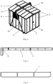
- a preassembled transformer substation comprises a plurality of strip-shaped assembling modules 1, a plurality of wall corner modules 2, connectors 3 which are located between the assembling modules 1 and the wall corner modules 2 (see figure 2 ), and a ridge 4; the assembling modules 1 are arranged longitudinally, and form, together with the wall corner modules 2 and the connectors 3, a wall body 10 and a door body 20 of the preassembled transformer substation; the assembling modules 1 are arranged transversely, and form, together with the ridge 4 and the connectors 3, a roof 30 of the preassembled transformer substation, wherein the ridge 4 is located at a center of the roof 30, and the assembling module 1 has one end connected with the ridge 4 and the other end inclined downward; each of the assembling module 1, the wall corner module 2, the connector 3 and the ridge 4 is a glass fiber reinforced plastic module.
- the assembling modules 1 forming the wall body 10 and the door body 20 and the assembling modules 1 supporting the roof 30 are made of the same material, wherein the wall body 10, the door body 20 and the roof 30 have the same die section, but are different in length only. Between the adjacent assembling modules 1, and between the assembling module 1 and the wall corner module 2 are inserted for securing by the connector 3, without need of rivets or screws, thus facilitating instalment.
- the inventive transformer substation has a strong capability of corrosion resistance.
- the assembling module 1 and the wall corner module 2 have a hollow bilayer structure formed by die drawing.
- the hollow bilayer structure has excellent capability of insulation for sound and heat.
- the connector 3 has a transverse section of I shape, both ends of the assembling module 1 and the wall corner module 2 can be inserted into two sides of the connector 3 and form an interference fit, thus functioning for secure connection.
- the shape of the ridge 4 is similar to that of the connector 3, but two sides of the ridge 4 incline downward.
- a roof 30 high in the middle and low on two sides is formed.
- an edge banding 5 is coated on a bottom side 11 of the wall body 10 and an outer edge 31 of the roof 30.
- the edge banding 5 functions for improving support and water proofing.
- the edge banding 5 on the bottom side 11 of the wall body 10 is connected, via a base wall body metal connector 12, with a base longitudinal beam 13.
- the base wall body metal connector 12 and the base longitudinal beam 13 function for securely supporting the whole preassembled transformer substation.
- the roof 30 and the wall body 10 are connected by a ridge support metal part 32, a roof wall body metal connector 33 and a top rail 6;
- the ridge support metal part 32 is arranged horizontally in a direction along the length of the assembling modules 1 of the roof 30,
- the top rail 6 is arranged horizontally in a direction perpendicular to the ridge support metal part 32, the roof wall body metal connector 33 connects the ridge support metal part 32 and the top rail 6;
- the top rail 6 is a glass fiber reinforced plastic module.
- the roof wall body metal connector 33 comprises two portions, one portion is connected with the ridge support metal part 32 and the other portion is connected with the assembling modules 1 forming the wall body, and the assembling module 1 is further connected with the top rail 6.
- the ridge support metal part 32 is installed below the ridge 4.
- the ridge support metal part 32 functions for supporting the ridge 4.
- a seal strip 7 is provided between the door body 20 and the wall body 10 and between the door body 20 and the roof 30, and a top seal part 8 is provided between the roof 30 and the door body 20, the seal strip 7 is inserted to the top seal part 8.
- the seal strip 7 is located between the wall body 10 and a door hinge 21 on the side of the door body 20.
- the seal strip 7 is located between the top seal part 8 and the top of the door body 20. The seal strip and the top seal part can function for better protection.
- the preassembled transformer substation has a transverse section of shape, with a transformer chamber 40 in the middle and a high voltage chamber 50 and a low voltage chamber 60 at its two ends, respectively; the high voltage chamber 50 is connected by a cable or a copper busbar with a high voltage terminal of a transformer 70, and the low voltage chamber 60 is connected by a cable or a copper busbar with a low voltage terminal of a transformer 70.
- the preassembled transformer substation has in its interior a grounding copper busbar which generally connects various grounding points.
- a heat dissipation window 9 is provided on a door of the transformer chamber 40 and on the wall body 10, and the heat dissipation window 9 comprises a plurality of L-shaped blades 91 spaced apart with one another.
- the preassembled transformer substation in the present invention can satisfy the requirements on distribution and transformation with a rated capacity in most areas, resistant to corrosion, simple and fast in installing, excellent in insulating property, light in weight, beautiful in appearance, and convenient for capacity regulation with its modularized design.
Landscapes
- Engineering & Computer Science (AREA)
- Power Engineering (AREA)
- Architecture (AREA)
- Civil Engineering (AREA)
- Structural Engineering (AREA)
- Patch Boards (AREA)
- Housings And Mounting Of Transformers (AREA)
- Building Environments (AREA)
- Body Structure For Vehicles (AREA)
Description
- The present invention relates to the field of electric power products, and specifically to a preassembled transformer substation used in the transmission and distribution system.
- Nowadays, the traditional preassembled box-type transformer substation uses an outer case material mainly including metal plate material and cement plate material. The outer case box of metal material can be made quickly, but is vulnerable to corrosion, and has a relatively high dependency on the environment and a poor capability of insulation for sound and heat; while the outer case box of cement of the preassembled transformer substation has a strong capability of corrosion resistance, but needs a long time to be made and installed and is relatively difficult for offsite assembly.So such boxes or enclosures are made of concrete or steel, or combinations of both. Furthermore it has to be considered, that steel as well as concrete are electric conductors. One further problem is, that steel or concrete can cause condensation of humity at the cold side of the wall. Examples for substations made of insulating material are disclosed in
US 2012/216393 A1 andUS 3 599 134 A . But the construction as well as the choice of material of componts are not optimized in sense of dielectric withstand. - The objective of the present invention is to overcome the defect of the prior art and provide a preassembled transformer substation, resistant in corrosion, electrically insulating against the environment and simple and fast in installing.According to that the invention is, that a preassembled transformer substation is provided having the features of
claim 1. Preferred embodiments are specified in the dependent claims. The use of pultrusion technique for the manufacture of the elements of the substation is for obtaining electrical insulation behavior, for a better dielectric behavior and to enlarge the creepage distances. - The substation is made of glass fiber reinforced Polyester, so called GRP). The enclosure of the substation so fulfills ingress protection degree IP 54; and that for the use of station for medium- and high-voltage application.
- With the technical solutions, the following beneficial effects can be achieved: as the assembling module and the like are glass fiber reinforced plastic modules, the glass fiber reinforced plastic has relatively good corrosion resistant property. Moreover, a modularized design is used to facilitate a fast installing.
- The subject matter of the Invention will be explained in more details in the following description illustrated in the drawings, in which:
-
Figure 1 is a structural diagram of a preassembled transformer substation in an embodiment of the invention. -
Figure 2 is a partial section view of a wall body in an embodiment of the invention. -
Figure 3 is a section view of an embodiment of an assembling module according to an embodiment of the invention. -
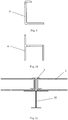
Figure 4 is a section view of a wall corner module in an embodiment of the invention. -
Figure 5 is a section view of a connector in an embodiment of the invention. -
Figure 6 is a section view of a ridge in an embodiment of the invention. -
Figure 7 is a partial structural diagram of a bottom of the wall body in an embodiment of the invention. -
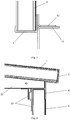
Figure 8 is a partial structural diagram of a structure between the wall body and the roof. -
Figure 9 is a section view of an edge banding in an embodiment of the invention. -
Figure 10 is a section view of a top rail in an embodiment of the invention. -
Figure 11 is a partial structural diagram of a roof. -
Figure 12 is a transverse partial cutaway view of a structure between the door body and the wall body in an embodiment of the invention. -
Figure 13 is a longitudinal partial cutaway view of a structure between the door body and the roof. -
Figure 14 is a section view of a seal strip. -
Figure 15 is a section view of a top seal part. -
Figure 16 a transverse cutaway view of the preassembled transformer substation. -
Figure 17 is a side view of a heat dissipation window. -
- 1--assembling module
- 2--wall corner module
- 3-connector
- 4-ridge
- 5--edge banding
- 6-top rail
- 7--seal strip
- 8--top seal part
- 9--heat dissipation window
- 10--wall body
- 20--door body
- 30-roof
- 40--transformer chamber
- 50--high voltage chamber
- 60--low voltage chamber
- 70-transformer
- 11--bottom side
- 12--base wall body metal connector
- 13--base longitudinal beam
- 21--door hinge
- 31--outer edge
- 32--ridge support metal part
- 33--roof wall body metal connector
- 91--blade
- Exemplary embodiments of the invention are described in conjunction with the accompanying drawings hereinafter. For the sake of clarity and conciseness, not all the features of actual implementations are described in the specification.
- As shown in
figure 1 , a preassembled transformer substation comprises a plurality of strip-shaped assembling modules 1, a plurality ofwall corner modules 2,connectors 3 which are located between the assemblingmodules 1 and the wall corner modules 2 (seefigure 2 ), and aridge 4; the assemblingmodules 1 are arranged longitudinally, and form, together with thewall corner modules 2 and theconnectors 3, awall body 10 and adoor body 20 of the preassembled transformer substation; the assemblingmodules 1 are arranged transversely, and form, together with theridge 4 and theconnectors 3, aroof 30 of the preassembled transformer substation, wherein theridge 4 is located at a center of theroof 30, and the assemblingmodule 1 has one end connected with theridge 4 and the other end inclined downward; each of the assemblingmodule 1, thewall corner module 2, theconnector 3 and theridge 4 is a glass fiber reinforced plastic module. - The assembling
modules 1 forming thewall body 10 and thedoor body 20 and the assemblingmodules 1 supporting theroof 30 are made of the same material, wherein thewall body 10, thedoor body 20 and theroof 30 have the same die section, but are different in length only. Between theadjacent assembling modules 1, and between the assemblingmodule 1 and thewall corner module 2 are inserted for securing by theconnector 3, without need of rivets or screws, thus facilitating instalment. As the glass fiber reinforced plastic has relatively good corrosion resistant property, the inventive transformer substation has a strong capability of corrosion resistance. - As shown in
figures 2-4 , the assemblingmodule 1 and thewall corner module 2 have a hollow bilayer structure formed by die drawing. The hollow bilayer structure has excellent capability of insulation for sound and heat. As shown infigure 5 , theconnector 3 has a transverse section of I shape, both ends of theassembling module 1 and thewall corner module 2 can be inserted into two sides of theconnector 3 and form an interference fit, thus functioning for secure connection. - As shown in
figure 6 , the shape of theridge 4 is similar to that of theconnector 3, but two sides of theridge 4 incline downward. When theassembling module 1 is inserted into theridge 4, aroof 30 high in the middle and low on two sides is formed. - As shown in
figures 7-8 , anedge banding 5 is coated on abottom side 11 of thewall body 10 and anouter edge 31 of theroof 30. The edge banding 5 functions for improving support and water proofing. As shown infigures 7 and9 , the edge banding 5 on thebottom side 11 of thewall body 10 is connected, via a base wallbody metal connector 12, with a baselongitudinal beam 13. The base wallbody metal connector 12 and the baselongitudinal beam 13 function for securely supporting the whole preassembled transformer substation. - As shown in
figures 8 and10 , theroof 30 and thewall body 10 are connected by a ridgesupport metal part 32, a roof wallbody metal connector 33 and atop rail 6; the ridgesupport metal part 32 is arranged horizontally in a direction along the length of the assemblingmodules 1 of theroof 30, thetop rail 6 is arranged horizontally in a direction perpendicular to the ridgesupport metal part 32, the roof wallbody metal connector 33 connects the ridgesupport metal part 32 and thetop rail 6; thetop rail 6 is a glass fiber reinforced plastic module. The roof wallbody metal connector 33 comprises two portions, one portion is connected with the ridgesupport metal part 32 and the other portion is connected with the assemblingmodules 1 forming the wall body, and theassembling module 1 is further connected with thetop rail 6. - As shown in
figure 11 , the ridgesupport metal part 32 is installed below theridge 4. The ridgesupport metal part 32 functions for supporting theridge 4. - As shown in
figures 12-15 , aseal strip 7 is provided between thedoor body 20 and thewall body 10 and between thedoor body 20 and theroof 30, and atop seal part 8 is provided between theroof 30 and thedoor body 20, theseal strip 7 is inserted to thetop seal part 8. Infigure 12 , theseal strip 7 is located between thewall body 10 and adoor hinge 21 on the side of thedoor body 20. Infigure 13 , theseal strip 7 is located between thetop seal part 8 and the top of thedoor body 20. The seal strip and the top seal part can function for better protection. - As shown in
figure 16 , the preassembled transformer substation has a transverse section of shape, with atransformer chamber 40 in the middle and ahigh voltage chamber 50 and alow voltage chamber 60 at its two ends, respectively; thehigh voltage chamber 50 is connected by a cable or a copper busbar with a high voltage terminal of atransformer 70, and thelow voltage chamber 60 is connected by a cable or a copper busbar with a low voltage terminal of atransformer 70. The preassembled transformer substation has in its interior a grounding copper busbar which generally connects various grounding points. - As shown in
figure 1 and17 , aheat dissipation window 9 is provided on a door of thetransformer chamber 40 and on thewall body 10, and theheat dissipation window 9 comprises a plurality of L-shapedblades 91 spaced apart with one another. - The preassembled transformer substation in the present invention can satisfy the requirements on distribution and transformation with a rated capacity in most areas, resistant to corrosion, simple and fast in installing, excellent in insulating property, light in weight, beautiful in appearance, and convenient for capacity regulation with its modularized design.
Claims (6)
- A preassembled transformer substation
comprising- a plurality of strip-shaped assembling modules (1),- a plurality of wall corner modules (2),- connectors (3) located between adjacent strip-shaped assembling modules (1) and between the wall corner modules (2) and adjacent strip-shaped assembling modules (1),- a wall body (10) which is made from the plurality of strip-shaped assembling modules (1),- a roof (30), which is made of other strip-shaped assembling modules (1),characterized by- a door comprising a door body (20) fixed at the wall body (10) with hinges (21), wherein the door body (20) is made of strip-shaped assembling modules (1),- a ridge (4), being located at a middle of the roof (30), wherein the roof (30) of the preassembled transformer substation is formed by the other strip-shaped assembling modules (1) together with the ridge (4) and the connectors (3), wherein the other strip-shaped assembling modules (1) are disposed on both sides of the ridge (4) and have a first end connected with the ridge (4) and a second end which is parallel to the first end and is inclined downward toward the wall body (10) so as to form the roof (30) which has an high portion close to the ridge (4) and two lower portions close to second end portions of the assembling modules (1),wherein the roof (30) and the wall body (10) are connected by a ridge support metal part (32) installed below the ridge (4), a top rail (6) and a roof wall body metal connector (33), wherein the roof wall body metal connector (33) connects, the ridge support metal part (32) and the top rail (6),
wherein the wall body (10), the door body (20), the top rail (6), the roof (30), the plurality of wall corner modules (2), the connectors (3) and the ridge (4) are made by pultrusion profiles of insulating material, wherein the insulating material is plastic or glasfiber reinforced Polyester, wherein the wall body (10), the roof (30), and the door body (20) are made in double layer insulating material with approximately 40 millimeter air distance between each layer, and wherein the hinges (21) of the door have fixation flanges being arranged in parallel and inside a space between an edge of the door body (20) and an edge of the wall body (10). - A preassembled transformer substation according to claim 1,
wherein each of the connectors (3) is a glass fiber reinforced plastic module. - A preassembled transformer substation according to claim 1 or 2,
wherein the assembling modules (1) and the wall corner modules (2) have a hollow die drawn bilayer structure. - A preassembled transformer substation according to claim 3, wherein the connector (3) has a transverse section of I -shape.
- A preassembled transformer substation according to claim 1 or 2,
wherein
the wall body (10) has a bottom side (11) and a top side, wherein the bottom side (11) is parallel to the top side, wherein the top side is facing an outer edge (31) of the roof (30) and wherein an edge banding (5) is coated on:- the bottom side (11) of the wall body (10); and- the outer edge (31) of the roof (30). - A preassembled transformer substation according to claim 5, wherein the edge banding (5) on the bottom side (11) of the wall body (10) is connected, via a base wall body metal connector (12), with a base longitudinal beam (13).
Applications Claiming Priority (2)
| Application Number | Priority Date | Filing Date | Title |
|---|---|---|---|
| CN201320453033.2U CN203415883U (en) | 2013-07-26 | 2013-07-26 | Preassembled transformer substation |
| PCT/EP2013/003602 WO2015010708A1 (en) | 2013-07-26 | 2013-11-28 | A preassembled transformer substation |
Publications (2)
| Publication Number | Publication Date |
|---|---|
| EP3025359A1 EP3025359A1 (en) | 2016-06-01 |
| EP3025359B1 true EP3025359B1 (en) | 2021-07-07 |
Family
ID=49880671
Family Applications (1)
| Application Number | Title | Priority Date | Filing Date |
|---|---|---|---|
| EP13811783.3A Active EP3025359B1 (en) | 2013-07-26 | 2013-11-28 | A preassembled transformer substation |
Country Status (4)
| Country | Link |
|---|---|
| EP (1) | EP3025359B1 (en) |
| CN (2) | CN203415883U (en) |
| AU (1) | AU2013395206B2 (en) |
| WO (1) | WO2015010708A1 (en) |
Families Citing this family (10)
| Publication number | Priority date | Publication date | Assignee | Title |
|---|---|---|---|---|
| CN109653549A (en) * | 2017-10-10 | 2019-04-19 | 湘能楚天电力有限公司 | A kind of magic cube type integrated transformer substation |
| CN109296230B (en) * | 2018-11-09 | 2023-08-25 | 尤利卡(江苏)集成电气有限公司 | Assembled transformer substation complete machine structure |
| CN111927137A (en) * | 2020-08-11 | 2020-11-13 | 广东电网有限责任公司广州供电局 | Installation method of double-layer power distribution room |
| CN112615284B (en) * | 2020-12-30 | 2024-12-27 | 河南中控电气有限公司 | A combined assembled box-type substation and assembly method thereof |
| CN113463954B (en) * | 2021-07-02 | 2022-10-28 | 广东电网有限责任公司 | 110kv urban transformer substation arrangement system |
| CN114122961B (en) * | 2021-11-26 | 2024-02-20 | 泰安市兰山电气有限公司 | Preassembled box-type transformer substation and use method |
| CN114123003B (en) * | 2021-11-27 | 2024-09-06 | 江西明正变电设备有限公司 | Intelligent preassembled transformer substation |
| CN115313228B (en) * | 2022-08-29 | 2025-07-22 | 特变电工京津冀智能科技有限公司 | Modularized box-type substation shell and assembly method thereof |
| CN116791938A (en) * | 2023-06-20 | 2023-09-22 | 上海思源输配电工程有限公司 | Split assembled prefabricated cabin for accommodating large transformer |
| CN117578252A (en) * | 2023-12-12 | 2024-02-20 | 海南金盘智能科技股份有限公司 | A 66KV fully insulated dry-type transformer prefabricated substation |
Family Cites Families (18)
| Publication number | Priority date | Publication date | Assignee | Title |
|---|---|---|---|---|
| DE1434673C3 (en) * | 1961-04-01 | 1974-01-24 | Kies- Und Betonwerk Marstetten Gmbh, 7971 Marstetten | Transformer station made of prefabricated concrete slabs and corner parts placed one on top of the other |
| US3629758A (en) * | 1969-10-14 | 1971-12-21 | Westinghouse Electric Corp | Transformer using noncombustible fluid dielectric for cooling |
| US3599134A (en) * | 1970-03-25 | 1971-08-10 | Westinghouse Electric Corp | Nonmetallic corrosion-resistant enclosure for electrical apparatus |
| JPS56118312A (en) * | 1980-02-21 | 1981-09-17 | Toshiba Corp | Tank for oil-filled electric apparatus |
| DE3135420A1 (en) * | 1981-09-07 | 1983-03-24 | Transformatoren Union Ag, 7000 Stuttgart | TRANSFORMER WITH A SMALL-WALLED BOILER |
| DE3904604A1 (en) * | 1988-02-17 | 1989-09-14 | Betonbau Gmbh | Wall comprising prefabricated compound units |
| CN2033950U (en) * | 1988-06-24 | 1989-03-08 | 开封开关厂 | Complete set distribution equipment |
| DE9405114U1 (en) * | 1994-03-25 | 1994-05-19 | Köhler, Klaus, 22587 Hamburg | Control cabinet made of concrete |
| CN2290133Y (en) * | 1996-10-25 | 1998-09-02 | 北京安瑞吉电气设备有限公司 | Box |
| FR2762029B1 (en) * | 1997-04-11 | 2000-09-29 | Isoglass | PANEL FOR THE MANUFACTURE OF TECHNICAL OR OTHER SHELTERS AND SHELTERS OBTAINED |
| US6161349A (en) * | 1999-07-22 | 2000-12-19 | Dynacom Industries, Inc. | System and method for fabricating enclosures |
| US20060181837A1 (en) * | 2003-03-19 | 2006-08-17 | Bing Sun | Combined transformer and prefabricated substations |
| CN1246866C (en) * | 2003-03-19 | 2006-03-22 | 上海科宏变电设备有限公司 | Combined transformer |
| US20090304440A1 (en) * | 2008-06-09 | 2009-12-10 | Ching Hai Wang | Aluminum window structure |
| WO2010031448A1 (en) * | 2008-09-19 | 2010-03-25 | Abb Technology Ag | A transformer assembly |
| DE102010026715B3 (en) * | 2010-07-09 | 2012-02-02 | Tts Trading & Technical Support Gmbh | Sheet steel housing for transformer station, has oil-tight base tub made of sheet steel, and two reciprocally arranged channels provided at base plate to accommodate device for lifting complete housing at respective ends |
| US8456838B2 (en) * | 2011-02-28 | 2013-06-04 | Abb Inc. | Arc-resistant dry type transformer enclosure having arc channels |
| US8375566B2 (en) * | 2011-02-28 | 2013-02-19 | Abb Inc. | Method of providing arc-resistant dry type transformer enclosure |
-
2013
- 2013-07-26 CN CN201320453033.2U patent/CN203415883U/en not_active Expired - Lifetime
- 2013-11-28 EP EP13811783.3A patent/EP3025359B1/en active Active
- 2013-11-28 WO PCT/EP2013/003602 patent/WO2015010708A1/en not_active Ceased
- 2013-11-28 AU AU2013395206A patent/AU2013395206B2/en active Active
- 2013-11-28 CN CN201380078527.XA patent/CN105518812B/en active Active
Non-Patent Citations (1)
| Title |
|---|
| None * |
Also Published As
| Publication number | Publication date |
|---|---|
| AU2013395206B2 (en) | 2017-05-11 |
| CN105518812B (en) | 2018-05-01 |
| WO2015010708A1 (en) | 2015-01-29 |
| CN105518812A (en) | 2016-04-20 |
| EP3025359A1 (en) | 2016-06-01 |
| CN203415883U (en) | 2014-01-29 |
| AU2013395206A1 (en) | 2016-02-11 |
Similar Documents
| Publication | Publication Date | Title |
|---|---|---|
| AU2013395206B2 (en) | A preassembled transformer substation | |
| US20120139683A1 (en) | Liquid cooling arrangement of an inductive component and a method for manufacturing an inductive component | |
| US20190312545A1 (en) | Photovoltaic module with a cross rail assembly | |
| CN202210646U (en) | 40.5 kV metal-armored withdrawable switching equipment applied to high altitude environment | |
| US20230135439A1 (en) | Delivery device for rooftop equipment and systems and method of installation | |
| CN108711722B (en) | Switching box applied to bus device | |
| CN110429403A (en) | A retractable bus connection device | |
| US9033721B2 (en) | Electrical connecting element | |
| WO2022221996A1 (en) | Bus-duct and associated manufacturing method | |
| CN104242202A (en) | High-voltage non-segregated phase bus and mounting method thereof | |
| CN209896513U (en) | Rainwater-proof device for box-type transformer substation | |
| CN208548674U (en) | A kind of waterproof movable type bus duct | |
| CN107346869B (en) | High-voltage armored movable-type switch cabinet wiring groove | |
| KR20140086096A (en) | Bus duct having housing corresponding to dustproof and waterproof grade | |
| CN211480458U (en) | Cable transfer device and power station transmission equipment | |
| CN210092388U (en) | Scalable generating line connecting device | |
| CN207925193U (en) | Sheath assembly and the high-tension switch cabinet for including such sheath assembly | |
| CN112236870B (en) | Photovoltaic module with cross rail assembly | |
| CN210744515U (en) | AC-DC feeding cabinet mounting beam | |
| CN218204055U (en) | An embossed barrier spur belt | |
| CN104348120A (en) | High voltage common bus | |
| CN223334236U (en) | Cable branch box | |
| KR200293430Y1 (en) | Insulated panel of cubicle for receiving and distributing electricity equipment | |
| CN205693139U (en) | A kind of high security electric power distributing cabinet | |
| CN220324924U (en) | High-current low-voltage cabinet bus assembly |
Legal Events
| Date | Code | Title | Description |
|---|---|---|---|
| PUAI | Public reference made under article 153(3) epc to a published international application that has entered the european phase |
Free format text: ORIGINAL CODE: 0009012 |
|
| 17P | Request for examination filed |
Effective date: 20160115 |
|
| AK | Designated contracting states |
Kind code of ref document: A1 Designated state(s): AL AT BE BG CH CY CZ DE DK EE ES FI FR GB GR HR HU IE IS IT LI LT LU LV MC MK MT NL NO PL PT RO RS SE SI SK SM TR |
|
| AX | Request for extension of the european patent |
Extension state: BA ME |
|
| RAP1 | Party data changed (applicant data changed or rights of an application transferred) |
Owner name: ABB SCHWEIZ AG |
|
| DAX | Request for extension of the european patent (deleted) | ||
| STAA | Information on the status of an ep patent application or granted ep patent |
Free format text: STATUS: EXAMINATION IS IN PROGRESS |
|
| 17Q | First examination report despatched |
Effective date: 20170301 |
|
| GRAP | Despatch of communication of intention to grant a patent |
Free format text: ORIGINAL CODE: EPIDOSNIGR1 |
|
| STAA | Information on the status of an ep patent application or granted ep patent |
Free format text: STATUS: GRANT OF PATENT IS INTENDED |
|
| INTG | Intention to grant announced |
Effective date: 20210201 |
|
| RIN1 | Information on inventor provided before grant (corrected) |
Inventor name: LIN, LU Inventor name: LIU, JIN LOU Inventor name: PEDERSEN, IVAN Inventor name: WANG, LIANG Inventor name: WANG, YAO MING |
|
| GRAS | Grant fee paid |
Free format text: ORIGINAL CODE: EPIDOSNIGR3 |
|
| GRAA | (expected) grant |
Free format text: ORIGINAL CODE: 0009210 |
|
| STAA | Information on the status of an ep patent application or granted ep patent |
Free format text: STATUS: THE PATENT HAS BEEN GRANTED |
|
| RAP3 | Party data changed (applicant data changed or rights of an application transferred) |
Owner name: ABB SCHWEIZ AG |
|
| AK | Designated contracting states |
Kind code of ref document: B1 Designated state(s): AL AT BE BG CH CY CZ DE DK EE ES FI FR GB GR HR HU IE IS IT LI LT LU LV MC MK MT NL NO PL PT RO RS SE SI SK SM TR |
|
| REG | Reference to a national code |
Ref country code: GB Ref legal event code: FG4D |
|
| REG | Reference to a national code |
Ref country code: AT Ref legal event code: REF Ref document number: 1409382 Country of ref document: AT Kind code of ref document: T Effective date: 20210715 |
|
| REG | Reference to a national code |
Ref country code: DE Ref legal event code: R096 Ref document number: 602013078269 Country of ref document: DE |
|
| REG | Reference to a national code |
Ref country code: IE Ref legal event code: FG4D |
|
| REG | Reference to a national code |
Ref country code: SE Ref legal event code: TRGR |
|
| REG | Reference to a national code |
Ref country code: LT Ref legal event code: MG9D |
|
| REG | Reference to a national code |
Ref country code: NL Ref legal event code: MP Effective date: 20210707 |
|
| REG | Reference to a national code |
Ref country code: AT Ref legal event code: MK05 Ref document number: 1409382 Country of ref document: AT Kind code of ref document: T Effective date: 20210707 |
|
| PG25 | Lapsed in a contracting state [announced via postgrant information from national office to epo] |
Ref country code: HR Free format text: LAPSE BECAUSE OF FAILURE TO SUBMIT A TRANSLATION OF THE DESCRIPTION OR TO PAY THE FEE WITHIN THE PRESCRIBED TIME-LIMIT Effective date: 20210707 Ref country code: RS Free format text: LAPSE BECAUSE OF FAILURE TO SUBMIT A TRANSLATION OF THE DESCRIPTION OR TO PAY THE FEE WITHIN THE PRESCRIBED TIME-LIMIT Effective date: 20210707 Ref country code: ES Free format text: LAPSE BECAUSE OF FAILURE TO SUBMIT A TRANSLATION OF THE DESCRIPTION OR TO PAY THE FEE WITHIN THE PRESCRIBED TIME-LIMIT Effective date: 20210707 Ref country code: FI Free format text: LAPSE BECAUSE OF FAILURE TO SUBMIT A TRANSLATION OF THE DESCRIPTION OR TO PAY THE FEE WITHIN THE PRESCRIBED TIME-LIMIT Effective date: 20210707 Ref country code: NO Free format text: LAPSE BECAUSE OF FAILURE TO SUBMIT A TRANSLATION OF THE DESCRIPTION OR TO PAY THE FEE WITHIN THE PRESCRIBED TIME-LIMIT Effective date: 20211007 Ref country code: PT Free format text: LAPSE BECAUSE OF FAILURE TO SUBMIT A TRANSLATION OF THE DESCRIPTION OR TO PAY THE FEE WITHIN THE PRESCRIBED TIME-LIMIT Effective date: 20211108 Ref country code: NL Free format text: LAPSE BECAUSE OF FAILURE TO SUBMIT A TRANSLATION OF THE DESCRIPTION OR TO PAY THE FEE WITHIN THE PRESCRIBED TIME-LIMIT Effective date: 20210707 Ref country code: AT Free format text: LAPSE BECAUSE OF FAILURE TO SUBMIT A TRANSLATION OF THE DESCRIPTION OR TO PAY THE FEE WITHIN THE PRESCRIBED TIME-LIMIT Effective date: 20210707 Ref country code: BG Free format text: LAPSE BECAUSE OF FAILURE TO SUBMIT A TRANSLATION OF THE DESCRIPTION OR TO PAY THE FEE WITHIN THE PRESCRIBED TIME-LIMIT Effective date: 20211007 Ref country code: LT Free format text: LAPSE BECAUSE OF FAILURE TO SUBMIT A TRANSLATION OF THE DESCRIPTION OR TO PAY THE FEE WITHIN THE PRESCRIBED TIME-LIMIT Effective date: 20210707 |
|
| PG25 | Lapsed in a contracting state [announced via postgrant information from national office to epo] |
Ref country code: PL Free format text: LAPSE BECAUSE OF FAILURE TO SUBMIT A TRANSLATION OF THE DESCRIPTION OR TO PAY THE FEE WITHIN THE PRESCRIBED TIME-LIMIT Effective date: 20210707 Ref country code: LV Free format text: LAPSE BECAUSE OF FAILURE TO SUBMIT A TRANSLATION OF THE DESCRIPTION OR TO PAY THE FEE WITHIN THE PRESCRIBED TIME-LIMIT Effective date: 20210707 Ref country code: GR Free format text: LAPSE BECAUSE OF FAILURE TO SUBMIT A TRANSLATION OF THE DESCRIPTION OR TO PAY THE FEE WITHIN THE PRESCRIBED TIME-LIMIT Effective date: 20211008 |
|
| REG | Reference to a national code |
Ref country code: DE Ref legal event code: R097 Ref document number: 602013078269 Country of ref document: DE |
|
| PG25 | Lapsed in a contracting state [announced via postgrant information from national office to epo] |
Ref country code: DK Free format text: LAPSE BECAUSE OF FAILURE TO SUBMIT A TRANSLATION OF THE DESCRIPTION OR TO PAY THE FEE WITHIN THE PRESCRIBED TIME-LIMIT Effective date: 20210707 |
|
| PLBE | No opposition filed within time limit |
Free format text: ORIGINAL CODE: 0009261 |
|
| STAA | Information on the status of an ep patent application or granted ep patent |
Free format text: STATUS: NO OPPOSITION FILED WITHIN TIME LIMIT |
|
| PG25 | Lapsed in a contracting state [announced via postgrant information from national office to epo] |
Ref country code: SM Free format text: LAPSE BECAUSE OF FAILURE TO SUBMIT A TRANSLATION OF THE DESCRIPTION OR TO PAY THE FEE WITHIN THE PRESCRIBED TIME-LIMIT Effective date: 20210707 Ref country code: SK Free format text: LAPSE BECAUSE OF FAILURE TO SUBMIT A TRANSLATION OF THE DESCRIPTION OR TO PAY THE FEE WITHIN THE PRESCRIBED TIME-LIMIT Effective date: 20210707 Ref country code: RO Free format text: LAPSE BECAUSE OF FAILURE TO SUBMIT A TRANSLATION OF THE DESCRIPTION OR TO PAY THE FEE WITHIN THE PRESCRIBED TIME-LIMIT Effective date: 20210707 Ref country code: EE Free format text: LAPSE BECAUSE OF FAILURE TO SUBMIT A TRANSLATION OF THE DESCRIPTION OR TO PAY THE FEE WITHIN THE PRESCRIBED TIME-LIMIT Effective date: 20210707 Ref country code: CZ Free format text: LAPSE BECAUSE OF FAILURE TO SUBMIT A TRANSLATION OF THE DESCRIPTION OR TO PAY THE FEE WITHIN THE PRESCRIBED TIME-LIMIT Effective date: 20210707 Ref country code: AL Free format text: LAPSE BECAUSE OF FAILURE TO SUBMIT A TRANSLATION OF THE DESCRIPTION OR TO PAY THE FEE WITHIN THE PRESCRIBED TIME-LIMIT Effective date: 20210707 |
|
| 26N | No opposition filed |
Effective date: 20220408 |
|
| PG25 | Lapsed in a contracting state [announced via postgrant information from national office to epo] |
Ref country code: MC Free format text: LAPSE BECAUSE OF FAILURE TO SUBMIT A TRANSLATION OF THE DESCRIPTION OR TO PAY THE FEE WITHIN THE PRESCRIBED TIME-LIMIT Effective date: 20210707 |
|
| REG | Reference to a national code |
Ref country code: CH Ref legal event code: PL |
|
| PG25 | Lapsed in a contracting state [announced via postgrant information from national office to epo] |
Ref country code: LU Free format text: LAPSE BECAUSE OF NON-PAYMENT OF DUE FEES Effective date: 20211128 Ref country code: BE Free format text: LAPSE BECAUSE OF NON-PAYMENT OF DUE FEES Effective date: 20211130 |
|
| REG | Reference to a national code |
Ref country code: BE Ref legal event code: MM Effective date: 20211130 |
|
| PG25 | Lapsed in a contracting state [announced via postgrant information from national office to epo] |
Ref country code: IE Free format text: LAPSE BECAUSE OF NON-PAYMENT OF DUE FEES Effective date: 20211128 |
|
| PG25 | Lapsed in a contracting state [announced via postgrant information from national office to epo] |
Ref country code: HU Free format text: LAPSE BECAUSE OF FAILURE TO SUBMIT A TRANSLATION OF THE DESCRIPTION OR TO PAY THE FEE WITHIN THE PRESCRIBED TIME-LIMIT; INVALID AB INITIO Effective date: 20131128 |
|
| PG25 | Lapsed in a contracting state [announced via postgrant information from national office to epo] |
Ref country code: CY Free format text: LAPSE BECAUSE OF FAILURE TO SUBMIT A TRANSLATION OF THE DESCRIPTION OR TO PAY THE FEE WITHIN THE PRESCRIBED TIME-LIMIT Effective date: 20210707 |
|
| PG25 | Lapsed in a contracting state [announced via postgrant information from national office to epo] |
Ref country code: LI Free format text: LAPSE BECAUSE OF NON-PAYMENT OF DUE FEES Effective date: 20220701 Ref country code: CH Free format text: LAPSE BECAUSE OF NON-PAYMENT OF DUE FEES Effective date: 20220701 |
|
| PG25 | Lapsed in a contracting state [announced via postgrant information from national office to epo] |
Ref country code: MK Free format text: LAPSE BECAUSE OF FAILURE TO SUBMIT A TRANSLATION OF THE DESCRIPTION OR TO PAY THE FEE WITHIN THE PRESCRIBED TIME-LIMIT Effective date: 20210707 |
|
| PG25 | Lapsed in a contracting state [announced via postgrant information from national office to epo] |
Ref country code: MT Free format text: LAPSE BECAUSE OF FAILURE TO SUBMIT A TRANSLATION OF THE DESCRIPTION OR TO PAY THE FEE WITHIN THE PRESCRIBED TIME-LIMIT Effective date: 20210707 |
|
| PG25 | Lapsed in a contracting state [announced via postgrant information from national office to epo] |
Ref country code: TR Free format text: LAPSE BECAUSE OF FAILURE TO SUBMIT A TRANSLATION OF THE DESCRIPTION OR TO PAY THE FEE WITHIN THE PRESCRIBED TIME-LIMIT Effective date: 20210707 |
|
| PGFP | Annual fee paid to national office [announced via postgrant information from national office to epo] |
Ref country code: DE Payment date: 20251119 Year of fee payment: 13 |
|
| PGFP | Annual fee paid to national office [announced via postgrant information from national office to epo] |
Ref country code: GB Payment date: 20251121 Year of fee payment: 13 |
|
| PGFP | Annual fee paid to national office [announced via postgrant information from national office to epo] |
Ref country code: IT Payment date: 20251125 Year of fee payment: 13 |
|
| PGFP | Annual fee paid to national office [announced via postgrant information from national office to epo] |
Ref country code: FR Payment date: 20251125 Year of fee payment: 13 |
|
| PGFP | Annual fee paid to national office [announced via postgrant information from national office to epo] |
Ref country code: SE Payment date: 20251119 Year of fee payment: 13 |