EP3024711B1 - System und verfahren zur frühzeitigen erkennung von ausfällen eines weichenantriebs - Google Patents
System und verfahren zur frühzeitigen erkennung von ausfällen eines weichenantriebs Download PDFInfo
- Publication number
- EP3024711B1 EP3024711B1 EP14829720.3A EP14829720A EP3024711B1 EP 3024711 B1 EP3024711 B1 EP 3024711B1 EP 14829720 A EP14829720 A EP 14829720A EP 3024711 B1 EP3024711 B1 EP 3024711B1
- Authority
- EP
- European Patent Office
- Prior art keywords
- detector bar
- point detector
- roller member
- predetermined distance
- sensing device
- Prior art date
- Legal status (The legal status is an assumption and is not a legal conclusion. Google has not performed a legal analysis and makes no representation as to the accuracy of the status listed.)
- Active
Links
- 238000001514 detection method Methods 0.000 title claims description 25
- 238000000034 method Methods 0.000 title claims description 8
- 230000033001 locomotion Effects 0.000 claims description 25
- 230000007246 mechanism Effects 0.000 claims description 9
- 230000005540 biological transmission Effects 0.000 claims description 7
- 230000001413 cellular effect Effects 0.000 claims description 3
- 238000004891 communication Methods 0.000 claims description 2
- 238000000926 separation method Methods 0.000 description 3
- 238000012423 maintenance Methods 0.000 description 2
- 238000012544 monitoring process Methods 0.000 description 2
- 230000004044 response Effects 0.000 description 2
- 230000003466 anti-cipated effect Effects 0.000 description 1
- 238000013459 approach Methods 0.000 description 1
- 230000010267 cellular communication Effects 0.000 description 1
- 239000000835 fiber Substances 0.000 description 1
- 238000010295 mobile communication Methods 0.000 description 1
- 238000012986 modification Methods 0.000 description 1
- 230000004048 modification Effects 0.000 description 1
- 238000004886 process control Methods 0.000 description 1
- 230000035945 sensitivity Effects 0.000 description 1
- 230000000087 stabilizing effect Effects 0.000 description 1
Images


Classifications
-
- B—PERFORMING OPERATIONS; TRANSPORTING
- B61—RAILWAYS
- B61L—GUIDING RAILWAY TRAFFIC; ENSURING THE SAFETY OF RAILWAY TRAFFIC
- B61L5/00—Local operating mechanisms for points or track-mounted scotch-blocks; Visible or audible signals; Local operating mechanisms for visible or audible signals
- B61L5/10—Locking mechanisms for points; Means for indicating the setting of points
- B61L5/107—Locking mechanisms for points; Means for indicating the setting of points electrical control of points position
-
- G—PHYSICS
- G01—MEASURING; TESTING
- G01M—TESTING STATIC OR DYNAMIC BALANCE OF MACHINES OR STRUCTURES; TESTING OF STRUCTURES OR APPARATUS, NOT OTHERWISE PROVIDED FOR
- G01M99/00—Subject matter not provided for in other groups of this subclass
-
- G—PHYSICS
- G01—MEASURING; TESTING
- G01M—TESTING STATIC OR DYNAMIC BALANCE OF MACHINES OR STRUCTURES; TESTING OF STRUCTURES OR APPARATUS, NOT OTHERWISE PROVIDED FOR
- G01M99/00—Subject matter not provided for in other groups of this subclass
- G01M99/008—Subject matter not provided for in other groups of this subclass by doing functionality tests
-
- B—PERFORMING OPERATIONS; TRANSPORTING
- B61—RAILWAYS
- B61L—GUIDING RAILWAY TRAFFIC; ENSURING THE SAFETY OF RAILWAY TRAFFIC
- B61L27/00—Central railway traffic control systems; Trackside control; Communication systems specially adapted therefor
- B61L27/50—Trackside diagnosis or maintenance, e.g. software upgrades
- B61L27/53—Trackside diagnosis or maintenance, e.g. software upgrades for trackside elements or systems, e.g. trackside supervision of trackside control system conditions
Definitions
- the present invention relates generally to railway monitoring apparatus and, more particularly to a system and method for identifying point detection calibration prior to point detector lock-out and switch machine failure.
- the present invention also relates to railway switch machines including such systems.
- a railway switch machine is used to divert a train from one track to another track,
- the switch machine is remotely operated and, thus, an operator cannot see the machine. Consequently, the status of the machine (e.g., points detected and mechanically locked for either a straight-through or turn-out move) is provided by electrical circuits that, in turn, are interlocked with signals governing movement of the trains.
- the term Normal (N) is employed for a straight-through move and the term Reverse (R) is employed for a turn-out move.
- indication circuits for switch machines were implemented with cam operated or other types of mechanical switches within the machine.
- the indication contacts of one machine are electrically connected in series with other machines. All interconnected machines must prove that their points are closed and mechanically locked before railroad signals are cleared, in order to permit movement of associated trains.
- Motor control is also provided by mechanical switches. Basically, the motor rotates in opposite directions for Normal and Reverse. Rotary motion of the motor is converted to linear motion within the machine to move and lock the points. If the motor is being driven Normal, then contacts within the machine open the circuit path that would, otherwise, permit continued movement in that direction when the limit of intended motion is reached. However, a path is maintained that permits movement in the Reverse direction. In between the extreme positions, both current paths are closed for movement of the motor in either direction.
- a battery voltage is fed from the wayside case to contacts of a first switch machine. Then, if those contacts are closed, the battery voltage is fed on to the next machine, and so on. If all the contacts in the, series string are closed, then the voltage fed back to the wayside case proves all switch machines are in correspondence, which is a condition necessary to clear signals.
- Switch machines such as, for example, without limitation, M-3, M-23A and M23-B switch machines, are designed to detect drifting of switch points beyond a predetermined distance and in response thereto signal a point failure, thus stopping any traffic travelling along the line.
- a switch machine must not give correspondence to clear a signal if the point closure is 0.635 cm (one-fourth of an inch) when a latch-out device is not present or 0.95 cm (three eights of an inch) when it is present.
- a linkage in the switch machine opens a set of contacts causing an open circuit and a loss of transmitted signal. In such instance, all train traffic along the line is stopped until a maintenance crew can physically inspect the switch machine and address/correct the cause for the undesired contact separation.
- US patent number US 5669587 shows point detection and indication with latch out mechanism.
- the latch out mechanism identifies a latch out condition when the railroad tracks are not at, or near, their proper positions before or after switching the railroad tracks.
- the detection and indication mechanism includes a four bar linkage which comprises a point detector bar, two cam followers, and a link arm assembly. The cam followers, supported in part by the link arm assembly, are connected to two point detector switches, so that the switch machine is operating when either one of these switches is closed or the railroad tracks are being switched.
- the latch out mechanism located on the link arm assembly, may produce and indicate a latch out condition, thereby causing the two point detector switches to be held open until the railroad tracks are switched again from a remote location or at the switch machine.
- a latch out switch may be added to the detection and indication mechanism in order to sustain the latch out condition and prevent the railroad tracks from being switched from a remote location until a safe condition is restored manually at the switch machine.
- the present invention provides a detection and indication system for use in a railway switch machine according to claim 1 and a railway switch machine according to claim 7 and a method of providing early detection of point failure in a railway switch machine according to claim 8..
- the first and second sensing device may further comprise a micro-switch which physically engages the respective secondary roller member.
- the micro-switch may be adjustably coupled to the mounting structure.
- the micro-switch may be adjustably coupled to the mounting structure via a slot
- the mounting structure may comprise indicia provided thereon for assisting in locating the first or second secondary roller member with regard to the first or second roller member of the switch machine respectively.
- the detection and indication system may further comprise a wireless transmission device in electrical communication with the first sensing device, the wireless transmission device being structured to wirelessly transmit a signal received from the first sensing device.
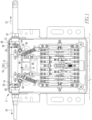
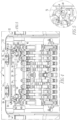
- FIGS. 1-5 there is generally provided an example embodiment of a detection and indication system 10 in accordance with the present invention shown installed in a switch machine 2.
- switch machine 2 In use, such switch machine 2 is located adjacent to a set of stock rails having a set of switching rails or switch points situated therebetween (not shown).
- the general structure and positioning of switch machines relative to railroad tracks is known in the art and, therefore, will not be described in detail.
- FIG. 1 there is shown an overhead planar view of a portion of the switch machine 2 in accordance with an example embodiment of the present invention with a cover (not shown) of the switch machine 2 removed to show internal details of the machine.
- a cover not shown
- the switch machine 2 Only the housing 12 of the switch machine and the elements relevant to the operation to the detection and indication system 10 are shown/described in detail herein.
- switch machine 2 includes a point detector bar 20 in the form of a long cylindrical rod positioned perpendicularly across the longitudinal axis of the switch machine 2 such that linear movement of the point detector bar 20 corresponds to movement by the switching rails relative to the position of stock rail on either side (not shown).
- the point detector bar 20 is capable of moving in two opposing directions: a normal direction 22 and a reverse direction 24.
- a normal direction 22 When the point detector bar 20 is moving toward the railroad tracks (i.e., to the right in FIG. 1 ), the bar is moving in a normal direction 22; when the point detector bar is moving in the opposite direction away from the railroad tracks (i.e., to the left in FIG. 1 ), the bar is moving in a reverse direction 24.
- point detector bar 20 includes a recess portion 26 formed at a fixed position thereon, such that the detection and indication system 10 can identify any movement of the switching rails by monitoring the position of the recess portion 26.
- the recess portion 26 is an elongated notch grooved at a small portion of the point detector bar 20 having conical slopes 28, 30 at both ends.
- the conical slopes 28, 30 connect a smaller-diameter surface 32 of the recess portion 26 to the larger-diameter surface 34 of the rest of the point detector bar.
- the normal cam follower 40 Adjacent to the point detector bar 20 is the normal cam follower 40 and the reverse cam follower 60. Since both cam followers 40, 60 have similar structures and functions, the normal cam follower is described in detail hereinafter, without equal reference to the reverse cam follower. Unless otherwise stated, the reverse cam follower 60 should be understood to have the same features as, or similar features to, the normal cam follower 40.
- the normal cam follower 40 has an elongated shape disposed about a pivot point 42 for stabilizing the normal cam follower 40 to the housing 12 of the switch machine 2. At one end of the cam follower 40 is a roller 44 and at an opposite end is an attachment point 46.
- the roller 44 is positioned adjacent to the point detector bar 20 whereas the attachment point 46 is pivotably coupled to a signal rod 48 which is moveable generally toward or away from the point detector bar 20.
- signal rod 48 is structured to cause contacts within the switch machine 2 to contact or separate, depending on the position of the rod 48.
- the point detector bar 20 is displaced in a position furthest to the right.
- roller 44 of cam follower 40 is disposed in recess portion 26.
- the point detector bar correspondingly slides in direction 24, thus causing roller 44 to engage and begin to travel along conical slope 28.
- cam follower 40 begins to rotate in a clockwise direction, thus causing the signal rod 48 to generally move toward the point detector bar 20.
- the arrangement is structured such that when the switch point reaches a predetermined distance (e.g., 0.635 cm (1/4 inch)) from the rail the signal rod 48 will have travelled a sufficient distance to initiate a signal that the point has moved away from the rail and thus the switch has failed. Upon such switch failure, rail traffic must be stopped until the switch can be manually inspected and reset or repaired.
- a predetermined distance e.g., 0.635 cm (1/4 inch)
- roller 44 will descend into recess portion 26 along conical slope 28.
- cam follower 40 rotates in a counter-clockwise direction, thus causing the signal rod to generally move away from the point detector bar 20, and at a predetermined point cause a signal to be initiated the that the switch point is within a predetermined distance of the rail
- Embodiments of the detection and indication system 10 described herein provide early detection against such switch failure through the use of sensing devices 50 installed adjacent the point detector bar 20 for both normal and reverse directions 22, 24.
- each sensing device 50 can trigger in any mode that is sensed to be out of calibration more than a predetermined amount (e.g., without limitation, 0.32 cm (1/8")).
- a signal can then be transmitted via a wired or wireless transmission (e.g., without limitation via cellular transmitter 52) to an Operation Control Center for the section of railway and/or to any other desired recipient (e.g., without limitation, maintenance personnel).
- each of the sensing devices 50 are connected to a Remote Terminal Unit (RTU) which provides for transmission of the output from each sensing device 50 to the governing authorities Operations Control Center (OCC).
- RTU Remote Terminal Unit
- OCC Operations Control Center
- the RTU is equipped with either a cellular modem (such as transmitter 52 in FIG. 1 ) that will utilize a subscriber identification module (SIM) card to access the existing cellular communication systems's global system for mobile communications (GSM) or an IEEE 802.11 a/b/g/n compliant wireless radio to access a Wireless Local Area network (WLAN).
- SIM subscriber identification module
- GSM global system for mobile communications
- WLAN Wireless Local Area network
- micro-switches 70 and 80 are utilized as sensing devices 50 to sense the position of the point detector bar 20.
- Detection and indication system 10 includes a mounting structure in the form of a bracket member 14 which is coupled to the housing 12 of the switch machine 2.
- Each of micro-switches 70 and 80 are adjustably coupled to the bracket member 14 via slots 16 formed in the bracket member 14. Such slots 16 allow for the position of each of the micro-switches 10 to be adjusted with respect to the corresponding roller of each of the cam followers 40, 60 of the of the switch machine such that the sensitivity (i.e., advance warning distance) of the particular micro-switch 70, 80 can be adjusted.
- each of the micro-switches 70, 80 physically engage the point detector bar 20 via a roller member 72, 82.
- Each roller member 72, 82 is pivotally coupled (via a respective pivot point 74, 84) to a respective micro-switch 70, 80.
- the micro-switch 70 can provide an early warning that the detector bar is nearing the point where a point failure will be indicated (i.e., when roller 42 will have travelled out of recessed portion 26), and thus service of the switch machine and related mechanisms should be performed.
- micro-switch 80 operates in a similar manner with respect to the reverse cam follower 60.
- indicia 17 may be provided on bracket 14 in order to assist in locating the roller 72 (or other sensing device) with regard to roller 42 of the switch machine along with a corresponding indicator 18 or other suitable reference provided on or in regard to the sensing device 50.
- photoelectric optic sensors are used as sensing device 50 to detect the position of the point detector bar for both normal and reverse points.
- the system can trigger in any mode that is sensed to be out of calibration more than 0.32 cm (1/8"). If this occurs, a signal is sent to the motor compartment of the switch, machine to a sensor amplifier via fiber optics. The signal then is sent from the sensor amplifier to a wireless router outside the switch machine which then sends a signal that the points are not aligned correctly.
Landscapes
- Physics & Mathematics (AREA)
- General Physics & Mathematics (AREA)
- Engineering & Computer Science (AREA)
- Mechanical Engineering (AREA)
- Train Traffic Observation, Control, And Security (AREA)
- Railway Tracks (AREA)
Claims (11)
- Detektions- und Anzeigesystem zur Verwendung in einer Eisenbahnweichenstellmaschine (2), die ein erstes Rollenelement (44) und ein zweites Rollenelement verwendet, welche physisch mit einem Punktdetektorbalken (20) interagieren, der mit einem oder mehreren Schaltpunkten gekoppelt ist, um eine Anzeige eines Punktausfalls bereitzustellen, wenn sich der Punktdetektorbalken (20) um einen ersten vorbestimmten Abstand von einer Ausgangsposition wegbewegt, wobei das System Folgendes umfasst:eine Anbringungsstruktur (14), die aufgebaut ist, um mit einem Gehäuse (12) der Weichenstellmaschine (2) gekoppelt zu sein;eine erste Sensorvorrichtung (50), die mit der Anbringungsstruktur (14) gekoppelt ist, die ein erstes Sekundärrollenelement (72) umfasst, wobei das erste Sekundärrollenelement positioniert und aufgebaut ist, um mit dem Punktdetektorbalken (20) in Eingriff zu stehen;eine zweite Sensorvorrichtung (50), die mit der Anbringungsstruktur (14) gekoppelt ist, wobei die zweite Sensorvorrichtung ein zweites Sekundärrollenelement (82) umfasst, wobei das zweite Sekundärrollenelement (82) positioniert und aufgebaut ist, um mit dem Punktdetektorbalken (20) in Eingriff zu stehen;wobei die erste und die zweite Sensorvorrichtung (50) positioniert und aufgebaut sind, um zu detektieren, wenn sich der Punktdetektorbalken (20) um einen zweiten vorbestimmten Abstand von einer Ausgangsposition wegbewegt, wobei der zweite vorbestimmte Abstand geringer ist als der erste vorbestimmte Abstand.
- Detektions- und Anzeigesystem nach Anspruch 1, wobei eine oder beide aus der ersten Sensorvorrichtung (50) und der zweiten Sensorvorrichtung (50) ferner einen Mikroschalter (70, 80) umfasst, der mit dem zweiten Sekundärrollenelement (72, 82) physisch in Eingriff steht.
- Detektions- und Anzeigesystem nach Anspruch 2, wobei der Mikroschalter (70, 80) einstellbar mit der Anbringungsstruktur (14) gekoppelt ist.
- Detektions- und Anzeigesystem nach Anspruch 3, wobei der Mikroschalter (70, 80) über einen Schlitz (16) einstellbar mit der Anbringungsstruktur (14) gekoppelt ist.
- Detektions- und Anzeigesystem nach Anspruch 4, wobei die Anbringungsstruktur (14) Zeichen umfasst, die darauf bereitgestellt sind, um das Lokalisieren des ersten Sekundärrollenelements (72) oder des zweiten Sekundärrollenelements (82) in Bezug auf das erste Rollenelement (44) bzw. das zweite Rollenelement der Weichenstellmaschine (2) zu unterstützen.
- Detektions- und Anzeigesystem nach Anspruch 1, ferner umfassend eine Drahtlosübertragungsvorrichtung in elektrischer Kommunikation mit der ersten Sensorvorrichtung (50), wobei die Drahtlosübertragungsvorrichtung aufgebaut ist, um ein Signal, das von der ersten Sensorvorrichtung (50) empfangen wird, drahtlos zu übertragen.
- Eisenbahn-Weichenstellmaschine (2), umfassend:ein Gehäuse (12);einen Punktdetektorbalken (20), der verschiebbar mit dem Gehäuse (12) gekoppelt ist,
wobei der Punktdetektorbalken (20) aufgebaut ist, um mit zumindest einem bewegbaren Schaltpunkt eines Eisenbahnsystems gekoppelt zu sein, wobei der Punkdetektorbalken (20) einen darin ausgebildeten Aussparungsabschnitt umfasst, wobei der Aussparungsabschnitt zumindest teilweise durch einen an einem Ende angeordneten geneigten Abschnitt definiert ist;ein erstes Rollenelement (44), das benachbart zum Punktdetektorbalken (20) angeordnet und positioniert ist, um mit dem geneigten Abschnitt des Aussparungsabschnitts physisch in Eingriff zu gelangen, wenn sich der Punktdetektorbalken (20) um einen vorbestimmten Abstand von einer Ausgangsposition wegbewegt, wobei das Rollenelement (44) mit einem Schaltmechanismus gekoppelt ist, der aufgebaut ist, um eine Anzeige eines Punktausfalls bereitzustellen, wenn sich der Punktdetektorbalken (20) um den ersten vorbestimmten Abstand von der Ausgangsposition wegbewegt,ein zweites Rollenelement, das benachbart zum Punktdetektorbalken (20) angeordnet und positioniert ist, um mit dem geneigten Abschnitt des Aussparungsabschnitts physisch in Eingriff zu gelangen, wenn sich der Punktdetektorbalken (20) um einen vorbestimmten Abstand von einer Ausgangsposition wegbewegt, wobei das Rollenelement (44) mit einem Schaltmechanismus gekoppelt ist, der aufgebaut ist, um eine Anzeige eines Punktausfalls bereitzustellen, wenn sich der Punktdetektorbalken (20) um den ersten vorbestimmten Abstand von der Ausgangsposition wegbewegt; undein Detektions- und Anzeigesystem nach einem der vorangegangenen Ansprüche, wobei:die Anbringungsstruktur (14) mit dem Gehäuse (12) gekoppelt ist unddas erste Sekundärrollenelement (72) benachbart zum Punktdetektorbalken (20) angeordnet und positioniert ist, um mit dem geneigten Abschnitt des Aussparungsabschnitts physisch in Eingriff zu gelangen, wenn sich der Punktdetektorbalken um den zweiten vorbestimmte Abstand von der Ausgangsposition wegbewegt, wobei das erste Sekundärrollenelement (72) derart mit der ersten Sensorvorrichtung (50) gekoppelt ist, dass durch die erste Sensorvorrichtung (50) ein Signal erzeugt wird, wenn sich der Punktdetektorbalken (20) um den zweiten vorbestimmten Abstand von der Ausgangsposition wegbewegt, wobei der zweite vorbestimmte Abstand geringer ist als der erste vorbestimmte Abstand;das zweite Sekundärrollenelement (82) benachbart zum Punktdetektorbalken (20) angeordnet und positioniert ist, um mit dem geneigten Abschnitt des Aussparungsabschnitts physisch in Eingriff zu gelangen, wenn sich der Punktdetektorbalken um den zweiten vorbestimmten Abstand von der Ausgangsposition wegbewegt, wobei das zweite Sekundärrollenelement (82) derart mit der zweiten Sensorvorrichtung (50) gekoppelt ist, dass durch die zweite Sensorvorrichtung (50) ein Signal erzeugt wird, wenn sich der Punktdetektorbalken (20) um den zweiten vorbestimmten Abstand von der Ausgangsposition wegbewegt, wobei der zweite vorbestimmte Abstand geringer ist als der erste vorbestimmte Abstand. - Verfahren des Bereitstellens einer Frühdetektion von Punktausfall in einer Eisenbahn-Weichenstellmaschine (2), die ein erstes Rollenelement (44) und ein zweites Rollenelement verwendet, welche physisch mit einem Punktdetektorbalken (20) interagieren, der mit einem oder mehreren Schaltpunkten gekoppelt ist, um eine Anzeige eines Punktausfalls bereitzustellen, wenn sich der Punktdetektorbalken (20) um einen ersten vorbestimmten Abstand von einer Ausgangsposition wegbewegt, wobei das Verfahren Folgendes umfasst:Positionieren einer ersten Sensorvorrichtung (50) benachbart zum Punktdetektorbalken (20), wobei die erste Sensorvorrichtung (50) ein erstes Sekundärrollenelement (72) umfasst, und wobei das Positionieren der ersten Sensorvorrichtung das Positionieren des ersten Sekundärrollenelements (72) derart umfasst, dass dieses mit dem Punktdetektorbalken in Eingriff gelangt und dass die erste Sensorvorrichtung (50) ein Signal erzeugt, wenn der Punktdetektorbalken (20) sich um einen zweiten vorbestimmten Abstand von der Ausgangsposition wegbewegt, wobei der zweite vorbestimmte Abstand geringer ist als der erste vorbestimmte Abstand; undPositionieren einer zweiten Sensorvorrichtung (50) benachbart zum Punktdetektorbalken (20), wobei die zweite Sensorvorrichtung (50) ein zweites Sekundärrollenelement (82) umfasst, und wobei das Positionieren der zweiten Sensorvorrichtung das Positionieren des zweiten Sekundärrollenelements (82) derart umfasst, dass dieses mit dem Punktdetektorbalken in Eingriff gelangt und dass die zweite Sensorvorrichtung (50) ein Signal erzeugt, wenn der Punktdetektorbalken (20) sich um einen zweiten vorbestimmten Abstand von der Ausgangsposition wegbewegt, wobei der zweite vorbestimmte Abstand geringer ist als der erste vorbestimmte Abstand.
- Verfahren nach Anspruch 8, ferner umfassend das Detektieren, dass der Punktdetektorbalken (20) sich zumindest um den zweiten vorbestimmten Abstand bewegt hat, über die erste Sensorvorrichtung (50) und als Antwort darauf das Übertragen eines Signals von der Weichenstellmaschine.
- Verfahren nach Anspruch 9, wobei das Übertragen eines Signals von der Weichenstellmaschine (2) das drahtlose Übertragen des Signals umfasst.
- Verfahren nach Anspruch 10, wobei das Signal über eine Mobilfunkverbindung übertragen wird.
Applications Claiming Priority (2)
| Application Number | Priority Date | Filing Date | Title |
|---|---|---|---|
| US201361857842P | 2013-07-24 | 2013-07-24 | |
| PCT/US2014/047970 WO2015013492A1 (en) | 2013-07-24 | 2014-07-24 | Point detection calibration before switch machine failure |
Publications (3)
| Publication Number | Publication Date |
|---|---|
| EP3024711A1 EP3024711A1 (de) | 2016-06-01 |
| EP3024711A4 EP3024711A4 (de) | 2017-04-05 |
| EP3024711B1 true EP3024711B1 (de) | 2024-03-13 |
Family
ID=52389674
Family Applications (1)
| Application Number | Title | Priority Date | Filing Date |
|---|---|---|---|
| EP14829720.3A Active EP3024711B1 (de) | 2013-07-24 | 2014-07-24 | System und verfahren zur frühzeitigen erkennung von ausfällen eines weichenantriebs |
Country Status (4)
| Country | Link |
|---|---|
| US (2) | US9592843B2 (de) |
| EP (1) | EP3024711B1 (de) |
| AU (1) | AU2014293102B2 (de) |
| WO (1) | WO2015013492A1 (de) |
Families Citing this family (5)
| Publication number | Priority date | Publication date | Assignee | Title |
|---|---|---|---|---|
| AU2015415489B2 (en) * | 2015-11-24 | 2019-06-20 | Siemens Mobility Pty Ltd. | Point machine and switch with snap-action and method of operating said point machine |
| US9889867B2 (en) * | 2015-12-28 | 2018-02-13 | Alstom Transport Technologies | Railroad switch machine |
| US10953897B2 (en) * | 2016-09-30 | 2021-03-23 | Hitachi Rail Sts Usa, Inc. | Electronic circuit controller for railway switch machine, railway switch machine and railway switching system including same |
| CA3100643A1 (en) | 2018-05-18 | 2019-11-21 | Hitachi Rail Sts Usa, Inc. | Non-powered shunting and track circuit disconnect mechanism for railway switch machine, railway switch machine and railway switching system including same |
| TWI760903B (zh) * | 2020-10-27 | 2022-04-11 | 台灣高速鐵路股份有限公司 | 道岔系統的定位辨識輔助裝置 |
Family Cites Families (21)
| Publication number | Priority date | Publication date | Assignee | Title |
|---|---|---|---|---|
| US2915622A (en) | 1955-12-20 | 1959-12-01 | Gen Railway Signal Co | Automatic switching system for classification yards |
| US3675233A (en) | 1969-09-05 | 1972-07-04 | Odon Steven Bencsics | Light reference system for railroad track surveying |
| AT399851B (de) | 1991-05-08 | 1995-08-25 | Vae Ag | Verfahren zum überwachen des zustandes von schienenweichen |
| US5669587A (en) * | 1994-08-19 | 1997-09-23 | General Railway Signal Corporation | Point detection and indication with latch out means |
| AT407983B (de) * | 1996-03-12 | 2001-07-25 | Vae Ag | Vorrichtung zum erfassen der positionen von schwenkbaren teilen einer weiche |
| US5806809A (en) | 1997-03-12 | 1998-09-15 | Danner; Don D. | Railroad switch point position sensing system and method |
| DE19821141A1 (de) * | 1998-05-12 | 1999-11-18 | Alcatel Sa | Vorrichtung zur Stromversorgung eines im Betrieb einer Weiche angeordneten elektrischen Verbrauchers und Diagnoseeinrichtung für eine Weiche |
| US6186448B1 (en) | 1998-09-08 | 2001-02-13 | Union Switch & Signal, Inc. | Captivity point detection system with single switch position target |
| US6296208B1 (en) | 1999-08-25 | 2001-10-02 | Union Switch & Signal, Inc. | Railway switch machine point detection system |
| US6366041B1 (en) * | 2000-01-24 | 2002-04-02 | Union Switch & Signal, Inc. | Railway switch machine motor control apparatus |
| US6427949B1 (en) | 2001-01-23 | 2002-08-06 | Alstom Signaling, Inc. | Contactless point detection system for railroad switch |
| US6474605B1 (en) | 2001-08-22 | 2002-11-05 | Union Switch & Signal, Inc. | Point detector sleeve for railroad switch machine and associated method |
| US6484974B1 (en) | 2001-09-10 | 2002-11-26 | Union Switch & Signal, Inc. | Controller for switch machine |
| US6578799B1 (en) * | 2001-12-06 | 2003-06-17 | Union Switch & Signal, Inc. | Modular point detector for railroad track signal |
| DE202004003435U1 (de) * | 2004-03-05 | 2005-07-14 | Hanning & Kahl Gmbh & Co. Kg | Prüfeinrichtung für Weichenanschlüsse |
| DE102005043305A1 (de) | 2005-09-07 | 2007-03-15 | Siemens Ag | System-Architektur zur Steuerung und Überwachung von Komponenten einer Eisenbahnsicherungsanlage |
| CN1986314B (zh) * | 2005-12-22 | 2012-07-25 | 株式会社日立制作所 | 信号保安系统 |
| PL1999001T3 (pl) * | 2006-03-29 | 2010-08-31 | PINTSCH TIEFENBACH GmbH | Urządzenie do włączania i nadzorowania instalacji sygnalizacji świetlnej w transporcie kolejowym |
| US8515697B2 (en) | 2010-05-06 | 2013-08-20 | Ansaldo Sts Usa, Inc. | Apparatus and method for vital signal state detection in overlay rail signal monitoring |
| US8341851B1 (en) * | 2011-06-21 | 2013-01-01 | Jim Arnold | Railroad switch signaling device |
| US8672286B2 (en) * | 2012-03-12 | 2014-03-18 | Laura Darré | Adjustable wall hanger |
-
2014
- 2014-07-24 EP EP14829720.3A patent/EP3024711B1/de active Active
- 2014-07-24 AU AU2014293102A patent/AU2014293102B2/en active Active
- 2014-07-24 US US14/339,686 patent/US9592843B2/en active Active
- 2014-07-24 WO PCT/US2014/047970 patent/WO2015013492A1/en active Application Filing
-
2017
- 2017-01-31 US US15/421,086 patent/US10370013B2/en active Active
Also Published As
| Publication number | Publication date |
|---|---|
| US20170137046A1 (en) | 2017-05-18 |
| US10370013B2 (en) | 2019-08-06 |
| AU2014293102B2 (en) | 2020-01-23 |
| WO2015013492A1 (en) | 2015-01-29 |
| EP3024711A4 (de) | 2017-04-05 |
| US9592843B2 (en) | 2017-03-14 |
| AU2014293102A1 (en) | 2016-02-11 |
| EP3024711A1 (de) | 2016-06-01 |
| US20150028164A1 (en) | 2015-01-29 |
Similar Documents
| Publication | Publication Date | Title |
|---|---|---|
| US10370013B2 (en) | System and method for identifying point detection calibration prior to point detector lock-out and switch machine failure | |
| US10953897B2 (en) | Electronic circuit controller for railway switch machine, railway switch machine and railway switching system including same | |
| EP3569471B1 (de) | Positives zugkontrollsystem und vorrichtung dafür | |
| US8814104B2 (en) | Train sensor unit for sensing radio communication based train, train position sensing system, and train position sensing method of the system | |
| US20110184621A1 (en) | Method and apparatus for increasing the stopping accuracy of a moving object | |
| US20150060608A1 (en) | Rail Vehicle Signal Enforcement and Separation Control | |
| KR102118672B1 (ko) | 열차 제어 방법 및 열차 제어 시스템 | |
| CN105151084B (zh) | 用于副轨道检测系统的设备及包含该设备的信号系统 | |
| US11479282B2 (en) | Method, vehicle device and controller for operating a track-bound traffic system | |
| JP2023506870A (ja) | 軌道車両のポジションを求める方法および監視システム | |
| US10946881B2 (en) | Automated testing and reporting of timely activation of crossing warning equipment based on data originated from a real-time train tracking system | |
| CN110740917A (zh) | 带有用于车辆的锁定监视器的索道 | |
| US11858538B2 (en) | Cable car and method for operating a cable car | |
| JP2010012932A (ja) | 列車監視システム | |
| EP3865370A1 (de) | Intelligente schiene und verfahren zur bestimmung eines belegungszustands eines gleisabschnittes | |
| KR102309103B1 (ko) | 열차선로 전환 시스템 | |
| JP3967898B2 (ja) | 自動列車制御装置 | |
| CN203974806U (zh) | 基于机器视觉的屏蔽门和列车门防夹超限监控装置 | |
| CA3083849C (en) | Train control network, method for communication and method for controlling train integrity | |
| KR101550239B1 (ko) | 단등형 3현시 led 신호기를 이용한 열차 제어 방법 및 장치 | |
| NL2017659B1 (nl) | Treindetectie eenheid | |
| RU2768688C1 (ru) | Единая цифровая бортовая платформа безопасности (БСБ-Е) | |
| RU2721440C1 (ru) | Система внешнего блокирования железнодорожной стрелки | |
| Kharote et al. | Automatic Protection System And Risk Mitigation In Railway Using PLC | |
| AU660788B2 (en) | Railway signalling system |
Legal Events
| Date | Code | Title | Description |
|---|---|---|---|
| PUAI | Public reference made under article 153(3) epc to a published international application that has entered the european phase |
Free format text: ORIGINAL CODE: 0009012 |
|
| 17P | Request for examination filed |
Effective date: 20160202 |
|
| AK | Designated contracting states |
Kind code of ref document: A1 Designated state(s): AL AT BE BG CH CY CZ DE DK EE ES FI FR GB GR HR HU IE IS IT LI LT LU LV MC MK MT NL NO PL PT RO RS SE SI SK SM TR |
|
| AX | Request for extension of the european patent |
Extension state: BA ME |
|
| DAX | Request for extension of the european patent (deleted) | ||
| A4 | Supplementary search report drawn up and despatched |
Effective date: 20170302 |
|
| RIC1 | Information provided on ipc code assigned before grant |
Ipc: B61L 5/10 20060101AFI20170224BHEP Ipc: B61L 27/00 20060101ALN20170224BHEP |
|
| STAA | Information on the status of an ep patent application or granted ep patent |
Free format text: STATUS: EXAMINATION IS IN PROGRESS |
|
| 17Q | First examination report despatched |
Effective date: 20190805 |
|
| STAA | Information on the status of an ep patent application or granted ep patent |
Free format text: STATUS: EXAMINATION IS IN PROGRESS |
|
| RAP1 | Party data changed (applicant data changed or rights of an application transferred) |
Owner name: HITACHI RAIL STS USA, INC. |
|
| STAA | Information on the status of an ep patent application or granted ep patent |
Free format text: STATUS: EXAMINATION IS IN PROGRESS |
|
| REG | Reference to a national code |
Ref country code: DE Ref legal event code: R079 Ref document number: 602014089700 Country of ref document: DE Free format text: PREVIOUS MAIN CLASS: B61L0001020000 Ipc: B61L0005100000 Ref legal event code: R079 Free format text: PREVIOUS MAIN CLASS: B61L0001020000 Ipc: B61L0005100000 |
|
| RIC1 | Information provided on ipc code assigned before grant |
Ipc: B61L 27/00 20060101ALN20230731BHEP Ipc: G01M 99/00 20110101ALI20230731BHEP Ipc: B61L 5/10 20060101AFI20230731BHEP |
|
| GRAP | Despatch of communication of intention to grant a patent |
Free format text: ORIGINAL CODE: EPIDOSNIGR1 |
|
| STAA | Information on the status of an ep patent application or granted ep patent |
Free format text: STATUS: GRANT OF PATENT IS INTENDED |
|
| RIC1 | Information provided on ipc code assigned before grant |
Ipc: B61L 27/00 20060101ALN20230908BHEP Ipc: G01M 99/00 20110101ALI20230908BHEP Ipc: B61L 5/10 20060101AFI20230908BHEP |
|
| INTG | Intention to grant announced |
Effective date: 20230926 |
|
| GRAS | Grant fee paid |
Free format text: ORIGINAL CODE: EPIDOSNIGR3 |
|
| GRAA | (expected) grant |
Free format text: ORIGINAL CODE: 0009210 |
|
| STAA | Information on the status of an ep patent application or granted ep patent |
Free format text: STATUS: THE PATENT HAS BEEN GRANTED |
|
| AK | Designated contracting states |
Kind code of ref document: B1 Designated state(s): AL AT BE BG CH CY CZ DE DK EE ES FI FR GB GR HR HU IE IS IT LI LT LU LV MC MK MT NL NO PL PT RO RS SE SI SK SM TR |
|
| REG | Reference to a national code |
Ref country code: GB Ref legal event code: FG4D |
|
| REG | Reference to a national code |
Ref country code: CH Ref legal event code: EP |
|
| REG | Reference to a national code |
Ref country code: DE Ref legal event code: R096 Ref document number: 602014089700 Country of ref document: DE |
|
| REG | Reference to a national code |
Ref country code: IE Ref legal event code: FG4D |
|
| PG25 | Lapsed in a contracting state [announced via postgrant information from national office to epo] |
Ref country code: LT Free format text: LAPSE BECAUSE OF FAILURE TO SUBMIT A TRANSLATION OF THE DESCRIPTION OR TO PAY THE FEE WITHIN THE PRESCRIBED TIME-LIMIT Effective date: 20240313 |
|
| REG | Reference to a national code |
Ref country code: LT Ref legal event code: MG9D |
|
| PG25 | Lapsed in a contracting state [announced via postgrant information from national office to epo] |
Ref country code: GR Free format text: LAPSE BECAUSE OF FAILURE TO SUBMIT A TRANSLATION OF THE DESCRIPTION OR TO PAY THE FEE WITHIN THE PRESCRIBED TIME-LIMIT Effective date: 20240614 |
|
| REG | Reference to a national code |
Ref country code: NL Ref legal event code: MP Effective date: 20240313 |
|
| PG25 | Lapsed in a contracting state [announced via postgrant information from national office to epo] |
Ref country code: RS Free format text: LAPSE BECAUSE OF FAILURE TO SUBMIT A TRANSLATION OF THE DESCRIPTION OR TO PAY THE FEE WITHIN THE PRESCRIBED TIME-LIMIT Effective date: 20240613 Ref country code: HR Free format text: LAPSE BECAUSE OF FAILURE TO SUBMIT A TRANSLATION OF THE DESCRIPTION OR TO PAY THE FEE WITHIN THE PRESCRIBED TIME-LIMIT Effective date: 20240313 |
|
| PG25 | Lapsed in a contracting state [announced via postgrant information from national office to epo] |
Ref country code: ES Free format text: LAPSE BECAUSE OF FAILURE TO SUBMIT A TRANSLATION OF THE DESCRIPTION OR TO PAY THE FEE WITHIN THE PRESCRIBED TIME-LIMIT Effective date: 20240313 |
|
| PG25 | Lapsed in a contracting state [announced via postgrant information from national office to epo] |
Ref country code: RS Free format text: LAPSE BECAUSE OF FAILURE TO SUBMIT A TRANSLATION OF THE DESCRIPTION OR TO PAY THE FEE WITHIN THE PRESCRIBED TIME-LIMIT Effective date: 20240613 Ref country code: NO Free format text: LAPSE BECAUSE OF FAILURE TO SUBMIT A TRANSLATION OF THE DESCRIPTION OR TO PAY THE FEE WITHIN THE PRESCRIBED TIME-LIMIT Effective date: 20240613 Ref country code: LT Free format text: LAPSE BECAUSE OF FAILURE TO SUBMIT A TRANSLATION OF THE DESCRIPTION OR TO PAY THE FEE WITHIN THE PRESCRIBED TIME-LIMIT Effective date: 20240313 Ref country code: HR Free format text: LAPSE BECAUSE OF FAILURE TO SUBMIT A TRANSLATION OF THE DESCRIPTION OR TO PAY THE FEE WITHIN THE PRESCRIBED TIME-LIMIT Effective date: 20240313 Ref country code: GR Free format text: LAPSE BECAUSE OF FAILURE TO SUBMIT A TRANSLATION OF THE DESCRIPTION OR TO PAY THE FEE WITHIN THE PRESCRIBED TIME-LIMIT Effective date: 20240614 Ref country code: FI Free format text: LAPSE BECAUSE OF FAILURE TO SUBMIT A TRANSLATION OF THE DESCRIPTION OR TO PAY THE FEE WITHIN THE PRESCRIBED TIME-LIMIT Effective date: 20240313 Ref country code: ES Free format text: LAPSE BECAUSE OF FAILURE TO SUBMIT A TRANSLATION OF THE DESCRIPTION OR TO PAY THE FEE WITHIN THE PRESCRIBED TIME-LIMIT Effective date: 20240313 Ref country code: BG Free format text: LAPSE BECAUSE OF FAILURE TO SUBMIT A TRANSLATION OF THE DESCRIPTION OR TO PAY THE FEE WITHIN THE PRESCRIBED TIME-LIMIT Effective date: 20240313 |
|
| REG | Reference to a national code |
Ref country code: AT Ref legal event code: MK05 Ref document number: 1665514 Country of ref document: AT Kind code of ref document: T Effective date: 20240313 |
|
| PG25 | Lapsed in a contracting state [announced via postgrant information from national office to epo] |
Ref country code: SE Free format text: LAPSE BECAUSE OF FAILURE TO SUBMIT A TRANSLATION OF THE DESCRIPTION OR TO PAY THE FEE WITHIN THE PRESCRIBED TIME-LIMIT Effective date: 20240313 Ref country code: LV Free format text: LAPSE BECAUSE OF FAILURE TO SUBMIT A TRANSLATION OF THE DESCRIPTION OR TO PAY THE FEE WITHIN THE PRESCRIBED TIME-LIMIT Effective date: 20240313 |
|
| PG25 | Lapsed in a contracting state [announced via postgrant information from national office to epo] |
Ref country code: NL Free format text: LAPSE BECAUSE OF FAILURE TO SUBMIT A TRANSLATION OF THE DESCRIPTION OR TO PAY THE FEE WITHIN THE PRESCRIBED TIME-LIMIT Effective date: 20240313 |