EP3024667B1 - Manual applicator - Google Patents
Manual applicator Download PDFInfo
- Publication number
- EP3024667B1 EP3024667B1 EP14749933.9A EP14749933A EP3024667B1 EP 3024667 B1 EP3024667 B1 EP 3024667B1 EP 14749933 A EP14749933 A EP 14749933A EP 3024667 B1 EP3024667 B1 EP 3024667B1
- Authority
- EP
- European Patent Office
- Prior art keywords
- handle
- housing
- manual applicator
- applicator
- manual
- Prior art date
- Legal status (The legal status is an assumption and is not a legal conclusion. Google has not performed a legal analysis and makes no representation as to the accuracy of the status listed.)
- Active
Links
- 239000000463 material Substances 0.000 claims description 25
- 239000000758 substrate Substances 0.000 claims description 9
- 238000011084 recovery Methods 0.000 claims description 6
- 239000002184 metal Substances 0.000 claims description 2
- 241001466460 Alveolata Species 0.000 claims 1
- 238000010168 coupling process Methods 0.000 claims 1
- 238000005859 coupling reaction Methods 0.000 claims 1
- 230000000295 complement effect Effects 0.000 description 4
- 238000004519 manufacturing process Methods 0.000 description 4
- 239000002313 adhesive film Substances 0.000 description 2
- 230000005489 elastic deformation Effects 0.000 description 2
- 238000001746 injection moulding Methods 0.000 description 2
- 238000012986 modification Methods 0.000 description 2
- 230000004048 modification Effects 0.000 description 2
- 229920001169 thermoplastic Polymers 0.000 description 2
- 239000004416 thermosoftening plastic Substances 0.000 description 2
- 230000006978 adaptation Effects 0.000 description 1
- 230000005540 biological transmission Effects 0.000 description 1
- 230000001413 cellular effect Effects 0.000 description 1
- 239000002131 composite material Substances 0.000 description 1
- 230000008094 contradictory effect Effects 0.000 description 1
- 238000005516 engineering process Methods 0.000 description 1
- 239000012530 fluid Substances 0.000 description 1
- 210000005224 forefinger Anatomy 0.000 description 1
- 239000007769 metal material Substances 0.000 description 1
- 229920000642 polymer Polymers 0.000 description 1
- 230000000750 progressive effect Effects 0.000 description 1
- 210000003813 thumb Anatomy 0.000 description 1
Images

Classifications
-
- B—PERFORMING OPERATIONS; TRANSPORTING
- B43—WRITING OR DRAWING IMPLEMENTS; BUREAU ACCESSORIES
- B43L—ARTICLES FOR WRITING OR DRAWING UPON; WRITING OR DRAWING AIDS; ACCESSORIES FOR WRITING OR DRAWING
- B43L19/00—Erasers, rubbers, or erasing devices; Holders therefor
-
- B—PERFORMING OPERATIONS; TRANSPORTING
- B43—WRITING OR DRAWING IMPLEMENTS; BUREAU ACCESSORIES
- B43K—IMPLEMENTS FOR WRITING OR DRAWING
- B43K23/00—Holders or connectors for writing implements; Means for protecting the writing-points
- B43K23/008—Holders comprising finger grips
-
- B—PERFORMING OPERATIONS; TRANSPORTING
- B43—WRITING OR DRAWING IMPLEMENTS; BUREAU ACCESSORIES
- B43L—ARTICLES FOR WRITING OR DRAWING UPON; WRITING OR DRAWING AIDS; ACCESSORIES FOR WRITING OR DRAWING
- B43L19/00—Erasers, rubbers, or erasing devices; Holders therefor
- B43L19/0056—Holders for erasers
- B43L19/0068—Hand-held holders
-
- B—PERFORMING OPERATIONS; TRANSPORTING
- B43—WRITING OR DRAWING IMPLEMENTS; BUREAU ACCESSORIES
- B43M—BUREAU ACCESSORIES NOT OTHERWISE PROVIDED FOR
- B43M11/00—Hand or desk devices of the office or personal type for applying liquid, other than ink, by contact to surfaces, e.g. for applying adhesive
- B43M11/06—Hand-held devices
-
- B—PERFORMING OPERATIONS; TRANSPORTING
- B65—CONVEYING; PACKING; STORING; HANDLING THIN OR FILAMENTARY MATERIAL
- B65H—HANDLING THIN OR FILAMENTARY MATERIAL, e.g. SHEETS, WEBS, CABLES
- B65H37/00—Article or web delivery apparatus incorporating devices for performing specified auxiliary operations
- B65H37/002—Web delivery apparatus, the web serving as support for articles, material or another web
- B65H37/005—Hand-held apparatus
- B65H37/007—Applicators for applying coatings, e.g. correction, colour or adhesive coatings
Definitions
- the present invention relates to the field of manual applicators, and more particularly to manual desktop applicators for applying a film to a substrate such as a sheet of paper.
- This film can be, for example, an opaque corrective film, a colored translucent film, an adhesive film, etc.
- manual applicators of this type include a housing and an application tip protruding beyond a front opening of the housing.
- Japanese patent application specifications JP H09 300 886 A and JP H11 170775 each disclosed an applicator comprising a housing, an application tip projecting beyond a front opening of the housing, and a C-shaped handle capable of pivoting between two different positions to allow two different grips.
- the versatility of this applicator remains limited, especially when it comes to adapting to the different grips of right-handed and left-handed people.
- the present disclosure aims to remedy these drawbacks.
- it aims to provide a manual applicator that can be easily adapted to different ways of taking it for its use, and this while keeping a limited size and complexity.
- this object is achieved thanks to the fact that the box has, in a first section plane and at least one second section plane different from the first section plane and not parallel to the first section plane, a same external contour capable of being housed by pressure in an internal contour of the handle, thus allowing the fixing of the handle on said housing in a first orientation and alternatively in at least a second orientation different from the first orientation, the handle being oriented in the first cutting plane in the first orientation and in the second cutting plane in the second orientation, and said first and second cutting planes being substantially aligned with a longitudinal axis of the housing.
- each user right-handed or left-handed, can easily fix this handle in the orientation best suited to his way of handling the manual applicator, so as to adapt the grip angle around this longitudinal axis.
- said outer contour of the case may be substantially symmetrical, thus making it possible to fit the case into the handle in at least two opposite orientations.
- the second section plane can be substantially perpendicular to the first section plane, although other angles can also be considered.
- the application tip has a substantially straight front edge.
- substantially straight is meant in this context an edge not diverging from a straight line over its entire width more than, for example, 10% of this width.
- At least one of said cutting planes is substantially parallel to said front edge of the application tip.
- the C-shaped handle comprises two longitudinal legs and a transverse connecting segment connecting proximal ends of said longitudinal legs.
- the applicator can include at least one protuberance on one of the handle and the case and a concavity on the other of the handle and the case to snap the handle onto the case.
- the latter may include a honeycomb part interposed between said internal contour and an external contour of the handle intended to offer a grip to a user.
- the handle may be able to be used. releasably fixed on said housing.
- the handle can comprise a first more rigid material and a second more flexible material, said first and second materials of the handle being able in particular to be coinjected.
- the greater rigidity of the first material allows the elastic deformation of the inner contour to exert sufficient pressure on the outer contour of the case to ensure its good fixation, while the greater flexibility of the outer contour offers a pleasant touch to the user.
- This first more rigid material can in particular form a core of the handle and / or be a metallic material.
- the material to be transferred to the substrate can in particular be in the form of a film.
- the applicator can comprise, inside the case, a spool for feeding a tape carrying the film to be transferred onto said substrate and a spool for collecting the carrier tape.
- the film can in particular be a corrective film.
- other types of film can be used, such as, for example, adhesive films or colored translucent films.
- the figure 1 illustrates the interior of the housing 3 of a manual applicator configured to allow the transfer of a film from a carrier tape 11 to a substrate.
- this applicator comprises, inside the housing 3, a supply reel 4 and a recovery reel 5 of the carrier tape.
- the applicator also comprises an application tip 6 projecting from a front opening 7 of the housing 3.
- the supply reel 4 is able to rotate about a first axis of rotation X 1 to unwind the carrier tape.
- the carrier tape 11 is recovered by the recovery reel 5, capable of rotating about a second axis of rotation X 2 , substantially parallel but offset with respect to the first axis of rotation X 1 .
- the carrier tape is guided in front of a front edge 6a of the application nozzle 6.
- a substrate such as that for example a sheet of paper
- the friction of the external face of the carrier tape against the substrate exerts a traction on the carrier tape between the end piece 6 and the supply reel 4 causing the progressive unwinding of the carrier tape wound around the supply reel 4.
- the applicator also comprises a belt 2 for transmitting the rotation of the supply spool 4 to the recovery reel 5 and in this way preserve a tension of the carrier tape between the end piece 6 and the recovery reel.
- other transmission means such as for example gears, can be considered for the same role.
- the figure 2 illustrates a handle 8 intended to be releasably fixed on the housing 3. More specifically, the handle 8, in the form of a C with two longitudinal tabs 8e, 8f, the proximal ends of which are connected by a transverse connecting segment 8g, has a inner contour 9 in which the box 3 can be lodged under pressure.
- the inner contour 9 is formed in an inner part 8a of the handle of relatively rigid material, surrounded by an outer part 8d of relatively flexible material and having a gripping surface 8c intended to facilitate gripping of the handle. handle 8 by the user.
- “relatively rigid material” and “relatively flexible material” is meant that the first has a modulus of elasticity which is substantially higher than the second.
- these two different materials can in particular be thermoplastics, thus allowing the production of the handle by injection-molding, and in particular by coinjection of the two materials.
- other materials and production methods can also be considered.
- the inner contour 9 of the handle 8 is substantially symmetrical.
- substantially symmetrical is meant, in the present context, that this contour is as symmetrical as the manufacturing technologies used can allow at a reasonable cost.
- the outer contour of the gripping surface 8c is asymmetrical so as to offer a particularly ergonomic grip.
- the box 3 has, in a longitudinal plane perpendicular to the front edge 6a of the application nozzle 6, an outer contour 10, complementary to the inner contour 9 of the handle 8 and also substantially symmetrical.
- the box 3 can come to be lodged by pressure inside the handle 8 oriented in this first plane.
- the housing 3 has substantially the same outer contour 10 also in a longitudinal plane aligned with the front edge 6a of the end piece application 6.
- the box 3 can therefore also come to be lodged by pressure inside the handle 8 in this second plane, perpendicular to the first.
- the handle 8 can be fixed with two opposite alternate orientations, to adapt the application tip 6 to right-handed or left-handed users.
- the handle 8 has protrusions 12,13 on, respectively, the distal ends of the longitudinal tabs 8e, 8f and the transverse connecting segment 8g.
- These protuberances 12,13 are oriented towards the inside of the handle 8 and configured so as to cooperate with complementary concavities 14,15 on the outside of the case 3 to stabilize the handle 8 on the case 3 by snap-fastening.
- at least one of the protuberances could be located on the housing and the handle have a complementary concavity.
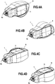
- the applicator 1 with the handle 8 oriented in a longitudinal plane perpendicular to the front edge 6a of the application nozzle 6.
- the handle 8 is also oriented in a longitudinal plane perpendicular to the front edge 6a of the applicator nozzle, but with an orientation opposite to that of the figure 4A .
- the handle 8 is oriented in a longitudinal plane aligned with the front edge 6a of the application nozzle 6.
- the handle 8 is also oriented in a longitudinal plane aligned with the front edge 6a of the applicator tip, but with an orientation opposite to that of the figure 4C .
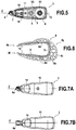
- the figure 5 illustrates the case 3 of an applicator 1 according to a second embodiment. Although different in detail, this case 3 is substantially similar to that of the first embodiment and the equivalent elements receive the same reference numerals in the drawings.
- the inner part 8a of the handle 8, illustrated on figure 6 has a core 8a 'made of relatively rigid material, on which is molded a relatively flexible material also forming a cellular part 8b and the outer part 8d having the gripping surface 8c.
- this core 8a ' can be formed by at least one blade or metal cable, folded in the shape of a C with two tabs extending into the longitudinal tabs 8e, 8f of the handle 8.
- others materials, such as polymers or composites can also be considered for this core 8a '.
- the relatively flexible material overmolded on this core can in particular be a thermoplastic, thus allowing the production of the handle by injection molding.
- at least one of the protuberances could be located on the case and the handle have a complementary concavity.
- the figures 7A and 7B illustrate how the box 3 according to this second embodiment also has substantially the same outer contour in a first longitudinal section plane and in a second longitudinal section plane perpendicular to the first.
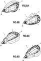
- FIGS. 8A to 8D illustrate, similarly to figures 4A to 4D , how the handle 8 of this second embodiment can therefore also be releasably fixed in the same orientations as in the first embodiment.
Landscapes
- Coating Apparatus (AREA)
- Adhesive Tape Dispensing Devices (AREA)
Description
La présente invention concerne le domaine des applicateurs manuels, et plus particulièrement des applicateurs manuels de bureau pour l'application d'un film sur un substrat tel qu'une feuille de papier. Ce film peut être, par exemple, un film correcteur opaque, un film translucide coloré, un film adhésif, etc.The present invention relates to the field of manual applicators, and more particularly to manual desktop applicators for applying a film to a substrate such as a sheet of paper. This film can be, for example, an opaque corrective film, a colored translucent film, an adhesive film, etc.
Typiquement, les applicateurs manuels de ce type comprennent un boitier et un embout d'application en saillie au-delà d'une ouverture avant du boitier.Typically, manual applicators of this type include a housing and an application tip protruding beyond a front opening of the housing.
On a remarqué que les utilisateurs diffèrent dans la manière dont ils préfèrent tenir des tels applicateurs dans la main pendant leur usage. Ainsi, certains préfèrent prendre l'applicateur entre le pouce et l'index dans un plan sensiblement parallèle à un bord avant de l'embout d'application, tandis que d'autres préfèrent le prendre dans un plan sensiblement perpendiculaire à ce bord avant. En outre, la prise est aussi différente suivant ce que l'utilisateur soit droitier ou gaucher. Toutefois, adapter le boitier de l'applicateur aux prises préférées par les différents utilisateurs potentiels, tant droitiers comme gauchers, est non seulement difficile, mais risque d'augmenter excessivement son encombrement et coût matériel.It has been noted that users differ in the manner in which they prefer to hold such applicators in their hand while in use. Thus, some prefer to take the applicator between the thumb and forefinger in a plane substantially parallel to a front edge of the applicator tip, while others prefer to take it in a plane substantially perpendicular to this front edge. In addition, the grip is also different depending on whether the user is right-handed or left-handed. However, adapting the casing of the applicator to the sockets preferred by the various potential users, both right-handed and left-handed, is not only difficult, but risks excessively increasing its size and material cost.
Les fascicules de demande de brevet japonais
La présente divulgation vise à remédier à ces inconvénients. En particulier elle vise à proposer un applicateur manuel pouvant être adapté facilement à des différentes manières de le prendre pour son utilisation, et ceci tout en gardant un encombrement et une complexité limités.The present disclosure aims to remedy these drawbacks. In particular, it aims to provide a manual applicator that can be easily adapted to different ways of taking it for its use, and this while keeping a limited size and complexity.
Dans au moins un mode de réalisation, ce but est atteint grâce au fait que le boitier présente, dans un premier plan de coupe et au moins un deuxième plan de coupe différent du premier plan de coupe et non parallèle au premier plan de coupe, un même contour extérieur apte à être logé à pression dans un contour intérieur de la poignée, permettant ainsi la fixation de la poignée sur ledit boitier dans une première orientation et alternativement dans au moins une deuxième orientation différente de la première orientation, la poignée étant orientée dans le premier plan de coupe dans la première orientation et dans le deuxième plan de coupe dans la deuxième orientation, et lesdits premier et deuxième plans de coupe étant sensiblement alignés avec un axe longitudinal du boitier.In at least one embodiment, this object is achieved thanks to the fact that the box has, in a first section plane and at least one second section plane different from the first section plane and not parallel to the first section plane, a same external contour capable of being housed by pressure in an internal contour of the handle, thus allowing the fixing of the handle on said housing in a first orientation and alternatively in at least a second orientation different from the first orientation, the handle being oriented in the first cutting plane in the first orientation and in the second cutting plane in the second orientation, and said first and second cutting planes being substantially aligned with a longitudinal axis of the housing.
Grâce à ces dispositions, chaque utilisateur, droitier ou gaucher, peut facilement fixer cette poignée dans l'orientation la mieux adaptée à sa manière de prendre l'applicateur manuel, de manière à adapter l'angle de saisie autour de cet axe longitudinal.By virtue of these arrangements, each user, right-handed or left-handed, can easily fix this handle in the orientation best suited to his way of handling the manual applicator, so as to adapt the grip angle around this longitudinal axis.
Afin notamment de permettre l'adaptation de l'applicateur manuel à des utilisateurs droitiers ou gauchers, ledit contour extérieur du boitier peut être sensiblement symétrique, permettant ainsi d'emboiter le boitier dans la poignée dans au moins deux orientations opposées.In order in particular to allow the adaptation of the manual applicator to right-handed or left-handed users, said outer contour of the case may be substantially symmetrical, thus making it possible to fit the case into the handle in at least two opposite orientations.
En particulier, le deuxième plan de coupe peut être sensiblement perpendiculaire au premier plan de coupe, quoique d'autres angles puissent aussi être envisagés.In particular, the second section plane can be substantially perpendicular to the first section plane, although other angles can also be considered.
Pour offrir une certaine largeur d'application du film, l'embout d'application présente un bord avant sensiblement droit. On entend par « sensiblement droit » dans ce contexte un bord ne divergeant pas d'une ligne droite sur toute sa largeur plus de, par exemple, 10% de cette largeur.To provide a certain application width of the film, the application tip has a substantially straight front edge. By "substantially straight" is meant in this context an edge not diverging from a straight line over its entire width more than, for example, 10% of this width.
Afin notamment d'adapter l'applicateur manuel aux utilisateurs préférant le saisir en largeur, au moins un desdits plans de coupe est sensiblement parallèle audit bord avant de l'embout d'application.In order in particular to adapt the manual applicator to users who prefer to grasp it in width, at least one of said cutting planes is substantially parallel to said front edge of the application tip.
La poignée en forme de C comprend deux pattes longitudinales et un segment transversal de liaison reliant des extrémités proximales desdites pattes longitudinales. Afin de mieux la stabiliser sur le boitier, l'applicateur peut comprendre au moins une protubérance sur l'un de la poignée et du boitier et une concavité sur l'autre de la poignée et du boitier pour encliqueter la poignée sur le boitier.The C-shaped handle comprises two longitudinal legs and a transverse connecting segment connecting proximal ends of said longitudinal legs. In order to better stabilize it on the case, the applicator can include at least one protuberance on one of the handle and the case and a concavity on the other of the handle and the case to snap the handle onto the case.
Afin notamment de réduire la masse et augmenter la flexibilité de la poignée, celle-ci peut comprendre une partie alvéolaire interposée entre ledit contour intérieur et un contour extérieur de la poignée destiné à offrir prise à un utilisateur.In order in particular to reduce the weight and increase the flexibility of the handle, the latter may include a honeycomb part interposed between said internal contour and an external contour of the handle intended to offer a grip to a user.
Afin notamment de permettre la modification subséquente de la configuration de l'applicateur manuel, pour l'adapter aux préférences d'un nouvel utilisateur, et/ou pour permettre la réutilisation de la poignée avec un nouveau boitier, la poignée peut être apte à être fixée de manière libérable sur ledit boitier.In order in particular to allow the subsequent modification of the configuration of the manual applicator, to adapt it to the preferences of a new user, and / or to allow the reuse of the handle with a new housing, the handle may be able to be used. releasably fixed on said housing.
Tandis qu'une certaine rigidité peut être requise pour assurer une bonne fixation de la poignée sur le boitier, une plus grande souplesse peut être préférable pour offrir une prise agréable à l'utilisateur. Afin de répondre à ces deux souhaits contradictoires, la poignée peut comprendre un premier matériau plus rigide et un deuxième matériau plus souple, lesdits premier et deuxième matériaux de la poignée pouvant notamment être coinjectés. La plus grande rigidité du premier matériau permet que la déformation élastique du contour intérieur exerce une pression suffisante sur le contour extérieur du boitier pour assurer sa bonne fixation, tandis que la plus grande souplesse du contour extérieur offre un tact agréable à l'utilisateur. Ce premier matériau plus rigide peut notamment former une âme de la poignée et/ou être un matériau métallique.While some rigidity may be required to ensure good attachment of the handle to the housing, more flexibility may be preferable to provide a comfortable grip for the user. In order to meet these two contradictory wishes, the handle can comprise a first more rigid material and a second more flexible material, said first and second materials of the handle being able in particular to be coinjected. The greater rigidity of the first material allows the elastic deformation of the inner contour to exert sufficient pressure on the outer contour of the case to ensure its good fixation, while the greater flexibility of the outer contour offers a pleasant touch to the user. This first more rigid material can in particular form a core of the handle and / or be a metallic material.
La matière à transférer sur le substrat peur notamment être en forme de film. Afin de permettre cela, l'applicateur peut comprendre, à l'intérieur du boitier, une bobine d'alimentation d'un ruban porteur du film à transférer sur ledit substrat et une bobine de récupération du ruban porteur. Le film peut notamment être un film correcteur. Toutefois, d'autres types de film peuvent être utilisés, comme par exemple des films adhésifs ou des films translucides colorés.The material to be transferred to the substrate can in particular be in the form of a film. In order to allow this, the applicator can comprise, inside the case, a spool for feeding a tape carrying the film to be transferred onto said substrate and a spool for collecting the carrier tape. The film can in particular be a corrective film. However, other types of film can be used, such as, for example, adhesive films or colored translucent films.
L'invention sera bien comprise et ses avantages apparaîtront mieux, à la lecture de la description détaillée qui suit, de deux modes de réalisation représentés à titre d'exemples non limitatifs. La description se réfère aux dessins annexés sur lesquels :
- la
figure 1 est une vue en coupe longitudinale du boitier d'un applicateur manuel suivant un premier mode de réalisation de la présente invention ; - la
figure 2 est une vue en coupe longitudinale d'une poignée destinée à être fixée sur le boitier de lafigure 1 pour former un applicateur manuel suivant le premier mode de réalisation de la présente invention ; - la
figure 3A est une vue latérale du boitier de lafigure 1 ; - la
figure 3B est une vue du haut du boitier de lafigure 1 ; - la
figure 4A est une perspective de l'applicateur manuel suivant le premier mode de réalisation, avec une première orientation de la poignée sur le boitier ; - la
figure 4B est une perspective de l'applicateur manuel suivant le premier mode de réalisation, avec une deuxième orientation de la poignée sur le boitier ; - la
figure 4C est une perspective de l'applicateur manuel suivant le premier mode de réalisation, avec une troisième orientation de la poignée sur le boitier ; - la
figure 4D est une perspective de l'applicateur manuel suivant le premier mode de réalisation, avec une quatrième orientation de la poignée sur le boitier ; - la
figure 5 est une vue en coupe longitudinale du boitier d'un applicateur manuel suivant un deuxième mode de réalisation de la présente invention ; - la
figure 6 est une vue en coupe longitudinale d'une poignée destinée à être fixée sur le boitier de lafigure 5 pour former un applicateur manuel suivant un deuxième mode de réalisation de la présente invention ; - la
figure 7A est une vue latérale du boitier de lafigure 5 ; - la
figure 7B est une vue du haut du boitier de lafigure 5 ; - la
figure 8A est une perspective de l'applicateur manuel suivant le deuxième mode de réalisation, avec une première orientation de la poignée sur le boitier ; - la
figure 8B est une perspective de l'applicateur manuel suivant le deuxième mode de réalisation, avec une deuxième orientation de la poignée sur le boitier ; - la
figure 8C est une perspective de l'applicateur manuel suivant le deuxième mode de réalisation, avec une troisième orientation de la poignée sur le boitier ; - la
figure 8D est une perspective de l'applicateur manuel suivant le deuxième mode de réalisation, avec une quatrième orientation de la poignée sur le boitier.
- the
figure 1 is a longitudinal sectional view of the housing of a manual applicator according to a first embodiment of the present invention; - the
figure 2 is a longitudinal sectional view of a handle intended to be fixed to the housing of thefigure 1 to form a manual applicator according to the first embodiment of the present invention; - the
figure 3A is a side view of the housing of thefigure 1 ; - the
figure 3B is a top view of the case of thefigure 1 ; - the
figure 4A is a perspective of the manual applicator according to the first embodiment, with a first orientation of the handle on the housing; - the
figure 4B is a perspective of the manual applicator according to the first embodiment, with a second orientation of the handle on the housing; - the
figure 4C is a perspective of the manual applicator according to the first embodiment, with a third orientation of the handle on the housing; - the
figure 4D is a perspective of the manual applicator according to the first embodiment, with a fourth orientation of the handle on the housing; - the
figure 5 is a longitudinal sectional view of the housing of a manual applicator according to a second embodiment of the present invention; - the
figure 6 is a longitudinal sectional view of a handle intended to be fixed to the housing of thefigure 5 to form a manual applicator according to a second embodiment of the present invention; - the
figure 7A is a side view of the housing of thefigure 5 ; - the
figure 7B is a top view of the case of thefigure 5 ; - the
figure 8A is a perspective of the manual applicator according to the second embodiment, with a first orientation of the handle on the housing; - the
figure 8B is a perspective of the manual applicator according to the second embodiment, with a second orientation of the handle on the housing; - the
figure 8C is a perspective of the manual applicator according to the second embodiment, with a third orientation of the handle on the housing; - the
figure 8D is a perspective of the manual applicator according to the second embodiment, with a fourth orientation of the handle on the housing.
La
La
Comme on peut voir sur la
On peut apprécier sur la
Afin d'assurer une fixation stable sur le boitier 3, la poignée 8 présente des protubérances 12,13 sur, respectivement, les extrémités distales des pattes longitudinales 8e, 8f et le segment transversal 8g de liaison. Ces protubérances 12,13 sont orientées vers l'intérieur de la poignée 8 et configurées de manière à coopérer avec des concavités complémentaires 14,15 sur l'extérieur du boitier 3 pour stabiliser la poignée 8 sur le boitier 3 par encliquetage. Alternativement, toutefois, au moins une des protubérances pourrait être située sur le boitier et la poignée présenter une concavité complémentaire.In order to ensure stable attachment to the
Sur la
La
Dans ce deuxième mode de réalisation, la partie intérieure 8a de la poignée 8, illustrée sur la
Les éléments restants de la poignée 8 de ce deuxième mode de réalisation sont équivalents à ceux du premier mode de réalisation, et reçoivent donc les mêmes chiffres de référence que dans les figures représentant le premier mode de réalisation.The remaining elements of the
Les
Les
Quoique la présente invention ait été décrite en se référant à des exemples de réalisation spécifiques, il est évident que des différentes modifications et changements peuvent être effectués sur ces exemples sans sortir de la portée générale de l'invention telle que définie par les revendications. En particulier, quoique l'invention ait été décrite par rapport à un applicateur manuel à ruban porteur, elle est également applicable à d'autres types d'applicateurs, y compris, par exemple, ceux comprenant un réservoir interne de matière fluide et un embout d'application poreux. En outre, des caractéristiques individuelles des différents modes de réalisation évoqués peuvent être combinées dans des modes de réalisation additionnels. Par conséquent, la description et les dessins doivent être considérés dans un sens illustratif plutôt que restrictif.Although the present invention has been described with reference to specific embodiments, it is obvious that various modifications and changes can be made to these examples without departing from the general scope of the invention as defined by the claims. In particular, although the invention has been described with respect to a manual carrier tape applicator, it is also applicable to other types of applicators, including, for example, those comprising an internal reservoir of fluid material and a nozzle. porous application. In addition, individual characteristics of the various embodiments mentioned can be combined in additional embodiments. Therefore, the description and the drawings should be taken in an illustrative rather than a restrictive sense.
Claims (12)
- Manual applicator (1) for applying a material to a substrate such as a sheet of paper, said manual applicator (1) comprising:a housing (3) having, in a first section plane and at least a second section plane which is different from the first section plane and not parallel to the first section plane, the same outer contour (10), said first and second section planes being substantially aligned with a longitudinal axis (Z) of the housing (3);an application tip (6) which projects beyond a front opening (7) of the housing (3) and has a substantially straight leading edge (6a); anda C-shaped handle (8) having two longitudinal arms (8e, 8f) and a transverse connecting segment (8g) which connects proximal ends of said longitudinal arms (8e, 8f);
the manual applicator being characterized in that at least one of said section planes is substantially parallel to said leading edge (6a) of the application tip (6), and in that said outer contour (10) of the housing (3) is suitable for being press-fitted into an inner contour (9) of the handle (8) in each of the first and second section planes, thus allowing the handle (8) to be attached to said housing (3) in a first orientation in which the handle (8) is oriented in the first section plane, and alternatively in at least a second orientation which is different from the first orientation and in which the handle (8) is oriented in the second section plane. - Manual applicator (1) according to claim 1, wherein said outer contour (10) of the housing (3) is substantially symmetrical.
- Manual applicator (1) according to either claim 1 or claim 2, wherein said first and second planes are substantially perpendicular to each other.
- Manual applicator (1) according to any of the preceding claims, comprising at least one protrusion on one of the handle (8) and the housing (3) and a recess on the other of the handle (8) and the housing (3) for snap-coupling the handle (8) to the housing (3).
- Manual applicator (1) according to any of the preceding claims, wherein said handle (8) comprises an alveolate portion (8b) positioned between said inner contour (9) and a gripping surface (8c) of the handle (8).
- Manual applicator (1) according to any of the preceding claims, wherein said handle (8) is suitable for being releasably attached to said housing (3).
- Manual applicator (1) according to any of the preceding claims, wherein said handle (8) comprises a first, more rigid material and a second, more flexible material.
- Manual applicator (1) according to claim 7, wherein the first material forms a core (8a') of the handle (8).
- Manual applicator (1) according to claim 8, wherein said first material is metal.
- Manual applicator (1) according to either claim 7 or claim 8, wherein said first and second materials of the handle (8) are co-injected.
- Manual applicator (1) according to any of the preceding claims, comprising, inside the housing (3), a supply reel (4) for a carrier tape of a film to be transferred onto said substrate, and a recovery reel (5) for the carrier tape.
- Manual applicator (1) according to claim 11, wherein said film is a corrective film.
Applications Claiming Priority (2)
| Application Number | Priority Date | Filing Date | Title |
|---|---|---|---|
| FR1357202A FR3008645B1 (en) | 2013-07-22 | 2013-07-22 | MANUAL APPLICATOR |
| PCT/FR2014/051873 WO2015011386A1 (en) | 2013-07-22 | 2014-07-21 | Manual applicator |
Publications (2)
| Publication Number | Publication Date |
|---|---|
| EP3024667A1 EP3024667A1 (en) | 2016-06-01 |
| EP3024667B1 true EP3024667B1 (en) | 2020-11-04 |
Family
ID=49151238
Family Applications (1)
| Application Number | Title | Priority Date | Filing Date |
|---|---|---|---|
| EP14749933.9A Active EP3024667B1 (en) | 2013-07-22 | 2014-07-21 | Manual applicator |
Country Status (6)
| Country | Link |
|---|---|
| US (1) | US10245879B2 (en) |
| EP (1) | EP3024667B1 (en) |
| JP (1) | JP6427185B2 (en) |
| CN (1) | CN105431303B (en) |
| FR (1) | FR3008645B1 (en) |
| WO (1) | WO2015011386A1 (en) |
Families Citing this family (1)
| Publication number | Priority date | Publication date | Assignee | Title |
|---|---|---|---|---|
| US11331784B2 (en) * | 2020-05-08 | 2022-05-17 | Edward P. Dyer | Ergonomic hand-held instrument |
Family Cites Families (16)
| Publication number | Priority date | Publication date | Assignee | Title |
|---|---|---|---|---|
| JP3711508B2 (en) * | 1996-05-15 | 2005-11-02 | 株式会社トンボ鉛筆 | Applicator container |
| US6019533A (en) * | 1997-08-18 | 2000-02-01 | Eversharp Pen Co. | Grip accessory, writing instrument and a method for enhancing comfort in a gripped surface |
| JPH11170775A (en) * | 1997-12-15 | 1999-06-29 | Sakura Color Prod Corp | Transfer implement |
| DE19824552A1 (en) * | 1998-06-03 | 1999-12-09 | Henkel Kgaa | Handheld device for transferring a film from a carrier tape to a substrate |
| US6652941B1 (en) * | 2000-09-27 | 2003-11-25 | Bic Corporation | Grip element and method of manufacture thereof |
| JP2003276393A (en) * | 2002-03-25 | 2003-09-30 | Pilot Corp | Cap-type writing utensil |
| US6705788B2 (en) * | 2002-07-12 | 2004-03-16 | Laura J. Gadberry | Hand support and writing instrument holder |
| JP4411970B2 (en) * | 2003-12-26 | 2010-02-10 | コクヨ株式会社 | Transfer tool |
| CN2717715Y (en) * | 2004-04-27 | 2005-08-17 | 上海北极熊文具胶带有限公司 | Correction tape box |
| JP4750388B2 (en) * | 2004-08-11 | 2011-08-17 | 株式会社壽 | Dispenser with cover |
| DE102007053449A1 (en) * | 2007-11-07 | 2009-05-20 | Henkel Ag & Co. Kgaa | Apparatus for transferring a film to a substrate |
| JP5429857B2 (en) | 2009-04-20 | 2014-02-26 | 日立マクセル株式会社 | Vibration adapter for mascara applicator |
| CN201573994U (en) * | 2009-11-04 | 2010-09-08 | 章良富 | Box type double-sided adhesive color tape |
| JP5582976B2 (en) * | 2010-11-15 | 2014-09-03 | プラス株式会社 | Coating film transfer tool |
| US8578999B2 (en) * | 2010-12-29 | 2013-11-12 | Sanford, L.P. | Variable clutch mechanism and correction tape dispenser with variable clutch mechanism |
| CN203032225U (en) * | 2012-12-24 | 2013-07-03 | 上海市新中高级中学 | Multifunctional correction tape |
-
2013
- 2013-07-22 FR FR1357202A patent/FR3008645B1/en not_active Expired - Fee Related
-
2014
- 2014-07-21 JP JP2016528585A patent/JP6427185B2/en not_active Expired - Fee Related
- 2014-07-21 US US14/906,315 patent/US10245879B2/en active Active
- 2014-07-21 EP EP14749933.9A patent/EP3024667B1/en active Active
- 2014-07-21 WO PCT/FR2014/051873 patent/WO2015011386A1/en active Application Filing
- 2014-07-21 CN CN201480041533.2A patent/CN105431303B/en active Active
Non-Patent Citations (1)
| Title |
|---|
| None * |
Also Published As
| Publication number | Publication date |
|---|---|
| US10245879B2 (en) | 2019-04-02 |
| JP2016530126A (en) | 2016-09-29 |
| US20160159139A1 (en) | 2016-06-09 |
| FR3008645B1 (en) | 2016-01-08 |
| CN105431303A (en) | 2016-03-23 |
| WO2015011386A1 (en) | 2015-01-29 |
| JP6427185B2 (en) | 2018-11-21 |
| EP3024667A1 (en) | 2016-06-01 |
| FR3008645A1 (en) | 2015-01-23 |
| CN105431303B (en) | 2018-06-05 |
Similar Documents
| Publication | Publication Date | Title |
|---|---|---|
| FR3034962B1 (en) | DEVICE FOR ASSEMBLING A BATTERY ELEMENT WITH THE USE TIP OF AN ELECTRONIC CIGARETTE TO WHICH IT IS ASSOCIATED | |
| EP2891420B1 (en) | Device for dispensing artificial eyelashes | |
| EP0632991B1 (en) | Sponge mop | |
| EP2268458A1 (en) | Storage holder for screwdriver bit | |
| FR2528984A1 (en) | PLUG FOR OPTICAL FIBER CONNECTOR AND CONNECTOR COMPRISING THE SAME | |
| WO2007068808A1 (en) | Spectacles with interchangeable multilayer sides | |
| WO2001021022A1 (en) | Device for locking in position a mobile part relative to a fixed part | |
| EP1749677B1 (en) | Cap with sharpener for a pencil in particular cosmetic, and pencil in particular cosmetic equipped with such a cap | |
| EP2809524B1 (en) | Writing instrument having a protective element for the retractable tip | |
| FR2796471A1 (en) | HIGH FLEXIBILITY ELASTIC HINGE | |
| EP3024667B1 (en) | Manual applicator | |
| FR2926489A1 (en) | TOOL FOR TRANSFERRING COATING FILM | |
| EP2678733A1 (en) | Sidepiece for eyeglasses, eyeglasses including at least one such sidepiece, and method for assembling such a sidepiece | |
| CA2253422A1 (en) | Toothbrush with handle comprising means for vertical storage | |
| EP2490774B1 (en) | Oversleeve element for a racquet handle, oversleeve element set, oversleeve, and corresponding method | |
| EP2525247B1 (en) | Spectacle frame with joint | |
| EP3402733B1 (en) | Manual device for applying a coating on a substrate using a tape, having an improved end piece | |
| FR3015188A1 (en) | PROTECTIVE COVER FOR AN ELECTRONIC CIGARETTE | |
| WO2011151686A1 (en) | Iron comprising a body connected to a power supply cord | |
| FR3067572A1 (en) | ARTIFICIAL EYE DISPENSER COMPRISING A PROTECTIVE CAP | |
| EP3526109B1 (en) | Device for attaching a scooter accessory and corresponding scooter | |
| EP4424392A1 (en) | Ground support device comprising a pole and a hand strap | |
| FR2868350A1 (en) | SCISSORS WITH OPEN SPRING | |
| WO2002094069A1 (en) | Liquid dispensing mouthpiece and water pocket equipped with same | |
| FR3028327A1 (en) | GLASSES WITH AUTOMATIC OPENING BRANCHES |
Legal Events
| Date | Code | Title | Description |
|---|---|---|---|
| PUAI | Public reference made under article 153(3) epc to a published international application that has entered the european phase |
Free format text: ORIGINAL CODE: 0009012 |
|
| 17P | Request for examination filed |
Effective date: 20160218 |
|
| AK | Designated contracting states |
Kind code of ref document: A1 Designated state(s): AL AT BE BG CH CY CZ DE DK EE ES FI FR GB GR HR HU IE IS IT LI LT LU LV MC MK MT NL NO PL PT RO RS SE SI SK SM TR |
|
| AX | Request for extension of the european patent |
Extension state: BA ME |
|
| DAX | Request for extension of the european patent (deleted) | ||
| STAA | Information on the status of an ep patent application or granted ep patent |
Free format text: STATUS: EXAMINATION IS IN PROGRESS |
|
| 17Q | First examination report despatched |
Effective date: 20171020 |
|
| GRAP | Despatch of communication of intention to grant a patent |
Free format text: ORIGINAL CODE: EPIDOSNIGR1 |
|
| STAA | Information on the status of an ep patent application or granted ep patent |
Free format text: STATUS: GRANT OF PATENT IS INTENDED |
|
| INTG | Intention to grant announced |
Effective date: 20200526 |
|
| GRAS | Grant fee paid |
Free format text: ORIGINAL CODE: EPIDOSNIGR3 |
|
| GRAA | (expected) grant |
Free format text: ORIGINAL CODE: 0009210 |
|
| STAA | Information on the status of an ep patent application or granted ep patent |
Free format text: STATUS: THE PATENT HAS BEEN GRANTED |
|
| AK | Designated contracting states |
Kind code of ref document: B1 Designated state(s): AL AT BE BG CH CY CZ DE DK EE ES FI FR GB GR HR HU IE IS IT LI LT LU LV MC MK MT NL NO PL PT RO RS SE SI SK SM TR |
|
| REG | Reference to a national code |
Ref country code: GB Ref legal event code: FG4D Free format text: NOT ENGLISH |
|
| REG | Reference to a national code |
Ref country code: CH Ref legal event code: EP |
|
| REG | Reference to a national code |
Ref country code: AT Ref legal event code: REF Ref document number: 1330339 Country of ref document: AT Kind code of ref document: T Effective date: 20201115 |
|
| REG | Reference to a national code |
Ref country code: IE Ref legal event code: FG4D Free format text: LANGUAGE OF EP DOCUMENT: FRENCH |
|
| REG | Reference to a national code |
Ref country code: DE Ref legal event code: R096 Ref document number: 602014071996 Country of ref document: DE |
|
| REG | Reference to a national code |
Ref country code: NL Ref legal event code: MP Effective date: 20201104 |
|
| REG | Reference to a national code |
Ref country code: AT Ref legal event code: MK05 Ref document number: 1330339 Country of ref document: AT Kind code of ref document: T Effective date: 20201104 |
|
| PG25 | Lapsed in a contracting state [announced via postgrant information from national office to epo] |
Ref country code: GR Free format text: LAPSE BECAUSE OF FAILURE TO SUBMIT A TRANSLATION OF THE DESCRIPTION OR TO PAY THE FEE WITHIN THE PRESCRIBED TIME-LIMIT Effective date: 20210205 Ref country code: PT Free format text: LAPSE BECAUSE OF FAILURE TO SUBMIT A TRANSLATION OF THE DESCRIPTION OR TO PAY THE FEE WITHIN THE PRESCRIBED TIME-LIMIT Effective date: 20210304 Ref country code: NO Free format text: LAPSE BECAUSE OF FAILURE TO SUBMIT A TRANSLATION OF THE DESCRIPTION OR TO PAY THE FEE WITHIN THE PRESCRIBED TIME-LIMIT Effective date: 20210204 Ref country code: FI Free format text: LAPSE BECAUSE OF FAILURE TO SUBMIT A TRANSLATION OF THE DESCRIPTION OR TO PAY THE FEE WITHIN THE PRESCRIBED TIME-LIMIT Effective date: 20201104 Ref country code: RS Free format text: LAPSE BECAUSE OF FAILURE TO SUBMIT A TRANSLATION OF THE DESCRIPTION OR TO PAY THE FEE WITHIN THE PRESCRIBED TIME-LIMIT Effective date: 20201104 |
|
| PG25 | Lapsed in a contracting state [announced via postgrant information from national office to epo] |
Ref country code: BG Free format text: LAPSE BECAUSE OF FAILURE TO SUBMIT A TRANSLATION OF THE DESCRIPTION OR TO PAY THE FEE WITHIN THE PRESCRIBED TIME-LIMIT Effective date: 20210204 Ref country code: AT Free format text: LAPSE BECAUSE OF FAILURE TO SUBMIT A TRANSLATION OF THE DESCRIPTION OR TO PAY THE FEE WITHIN THE PRESCRIBED TIME-LIMIT Effective date: 20201104 Ref country code: ES Free format text: LAPSE BECAUSE OF FAILURE TO SUBMIT A TRANSLATION OF THE DESCRIPTION OR TO PAY THE FEE WITHIN THE PRESCRIBED TIME-LIMIT Effective date: 20201104 Ref country code: LV Free format text: LAPSE BECAUSE OF FAILURE TO SUBMIT A TRANSLATION OF THE DESCRIPTION OR TO PAY THE FEE WITHIN THE PRESCRIBED TIME-LIMIT Effective date: 20201104 Ref country code: IS Free format text: LAPSE BECAUSE OF FAILURE TO SUBMIT A TRANSLATION OF THE DESCRIPTION OR TO PAY THE FEE WITHIN THE PRESCRIBED TIME-LIMIT Effective date: 20210304 Ref country code: SE Free format text: LAPSE BECAUSE OF FAILURE TO SUBMIT A TRANSLATION OF THE DESCRIPTION OR TO PAY THE FEE WITHIN THE PRESCRIBED TIME-LIMIT Effective date: 20201104 Ref country code: PL Free format text: LAPSE BECAUSE OF FAILURE TO SUBMIT A TRANSLATION OF THE DESCRIPTION OR TO PAY THE FEE WITHIN THE PRESCRIBED TIME-LIMIT Effective date: 20201104 |
|
| REG | Reference to a national code |
Ref country code: LT Ref legal event code: MG9D |
|
| PG25 | Lapsed in a contracting state [announced via postgrant information from national office to epo] |
Ref country code: HR Free format text: LAPSE BECAUSE OF FAILURE TO SUBMIT A TRANSLATION OF THE DESCRIPTION OR TO PAY THE FEE WITHIN THE PRESCRIBED TIME-LIMIT Effective date: 20201104 |
|
| PG25 | Lapsed in a contracting state [announced via postgrant information from national office to epo] |
Ref country code: LT Free format text: LAPSE BECAUSE OF FAILURE TO SUBMIT A TRANSLATION OF THE DESCRIPTION OR TO PAY THE FEE WITHIN THE PRESCRIBED TIME-LIMIT Effective date: 20201104 Ref country code: SK Free format text: LAPSE BECAUSE OF FAILURE TO SUBMIT A TRANSLATION OF THE DESCRIPTION OR TO PAY THE FEE WITHIN THE PRESCRIBED TIME-LIMIT Effective date: 20201104 Ref country code: RO Free format text: LAPSE BECAUSE OF FAILURE TO SUBMIT A TRANSLATION OF THE DESCRIPTION OR TO PAY THE FEE WITHIN THE PRESCRIBED TIME-LIMIT Effective date: 20201104 Ref country code: EE Free format text: LAPSE BECAUSE OF FAILURE TO SUBMIT A TRANSLATION OF THE DESCRIPTION OR TO PAY THE FEE WITHIN THE PRESCRIBED TIME-LIMIT Effective date: 20201104 Ref country code: CZ Free format text: LAPSE BECAUSE OF FAILURE TO SUBMIT A TRANSLATION OF THE DESCRIPTION OR TO PAY THE FEE WITHIN THE PRESCRIBED TIME-LIMIT Effective date: 20201104 Ref country code: SM Free format text: LAPSE BECAUSE OF FAILURE TO SUBMIT A TRANSLATION OF THE DESCRIPTION OR TO PAY THE FEE WITHIN THE PRESCRIBED TIME-LIMIT Effective date: 20201104 |
|
| REG | Reference to a national code |
Ref country code: DE Ref legal event code: R097 Ref document number: 602014071996 Country of ref document: DE |
|
| PG25 | Lapsed in a contracting state [announced via postgrant information from national office to epo] |
Ref country code: DK Free format text: LAPSE BECAUSE OF FAILURE TO SUBMIT A TRANSLATION OF THE DESCRIPTION OR TO PAY THE FEE WITHIN THE PRESCRIBED TIME-LIMIT Effective date: 20201104 |
|
| PLBE | No opposition filed within time limit |
Free format text: ORIGINAL CODE: 0009261 |
|
| STAA | Information on the status of an ep patent application or granted ep patent |
Free format text: STATUS: NO OPPOSITION FILED WITHIN TIME LIMIT |
|
| 26N | No opposition filed |
Effective date: 20210805 |
|
| PG25 | Lapsed in a contracting state [announced via postgrant information from national office to epo] |
Ref country code: IT Free format text: LAPSE BECAUSE OF FAILURE TO SUBMIT A TRANSLATION OF THE DESCRIPTION OR TO PAY THE FEE WITHIN THE PRESCRIBED TIME-LIMIT Effective date: 20201104 Ref country code: AL Free format text: LAPSE BECAUSE OF FAILURE TO SUBMIT A TRANSLATION OF THE DESCRIPTION OR TO PAY THE FEE WITHIN THE PRESCRIBED TIME-LIMIT Effective date: 20201104 Ref country code: NL Free format text: LAPSE BECAUSE OF FAILURE TO SUBMIT A TRANSLATION OF THE DESCRIPTION OR TO PAY THE FEE WITHIN THE PRESCRIBED TIME-LIMIT Effective date: 20201104 |
|
| PG25 | Lapsed in a contracting state [announced via postgrant information from national office to epo] |
Ref country code: SI Free format text: LAPSE BECAUSE OF FAILURE TO SUBMIT A TRANSLATION OF THE DESCRIPTION OR TO PAY THE FEE WITHIN THE PRESCRIBED TIME-LIMIT Effective date: 20201104 |
|
| REG | Reference to a national code |
Ref country code: CH Ref legal event code: PL |
|
| PG25 | Lapsed in a contracting state [announced via postgrant information from national office to epo] |
Ref country code: MC Free format text: LAPSE BECAUSE OF FAILURE TO SUBMIT A TRANSLATION OF THE DESCRIPTION OR TO PAY THE FEE WITHIN THE PRESCRIBED TIME-LIMIT Effective date: 20201104 |
|
| REG | Reference to a national code |
Ref country code: BE Ref legal event code: MM Effective date: 20210731 |
|
| PG25 | Lapsed in a contracting state [announced via postgrant information from national office to epo] |
Ref country code: LI Free format text: LAPSE BECAUSE OF NON-PAYMENT OF DUE FEES Effective date: 20210731 Ref country code: CH Free format text: LAPSE BECAUSE OF NON-PAYMENT OF DUE FEES Effective date: 20210731 |
|
| PG25 | Lapsed in a contracting state [announced via postgrant information from national office to epo] |
Ref country code: IS Free format text: LAPSE BECAUSE OF FAILURE TO SUBMIT A TRANSLATION OF THE DESCRIPTION OR TO PAY THE FEE WITHIN THE PRESCRIBED TIME-LIMIT Effective date: 20210304 Ref country code: LU Free format text: LAPSE BECAUSE OF NON-PAYMENT OF DUE FEES Effective date: 20210721 |
|
| PG25 | Lapsed in a contracting state [announced via postgrant information from national office to epo] |
Ref country code: IE Free format text: LAPSE BECAUSE OF NON-PAYMENT OF DUE FEES Effective date: 20210721 Ref country code: BE Free format text: LAPSE BECAUSE OF NON-PAYMENT OF DUE FEES Effective date: 20210731 |
|
| PG25 | Lapsed in a contracting state [announced via postgrant information from national office to epo] |
Ref country code: HU Free format text: LAPSE BECAUSE OF FAILURE TO SUBMIT A TRANSLATION OF THE DESCRIPTION OR TO PAY THE FEE WITHIN THE PRESCRIBED TIME-LIMIT; INVALID AB INITIO Effective date: 20140721 |
|
| PG25 | Lapsed in a contracting state [announced via postgrant information from national office to epo] |
Ref country code: CY Free format text: LAPSE BECAUSE OF FAILURE TO SUBMIT A TRANSLATION OF THE DESCRIPTION OR TO PAY THE FEE WITHIN THE PRESCRIBED TIME-LIMIT Effective date: 20201104 |
|
| PGFP | Annual fee paid to national office [announced via postgrant information from national office to epo] |
Ref country code: DE Payment date: 20230620 Year of fee payment: 10 |
|
| PG25 | Lapsed in a contracting state [announced via postgrant information from national office to epo] |
Ref country code: MK Free format text: LAPSE BECAUSE OF FAILURE TO SUBMIT A TRANSLATION OF THE DESCRIPTION OR TO PAY THE FEE WITHIN THE PRESCRIBED TIME-LIMIT Effective date: 20201104 |
|
| PGFP | Annual fee paid to national office [announced via postgrant information from national office to epo] |
Ref country code: GB Payment date: 20240620 Year of fee payment: 11 |
|
| PGFP | Annual fee paid to national office [announced via postgrant information from national office to epo] |
Ref country code: FR Payment date: 20240619 Year of fee payment: 11 |