EP3024166A1 - Communication system having synchronized units and synchronization method for units - Google Patents
Communication system having synchronized units and synchronization method for units Download PDFInfo
- Publication number
- EP3024166A1 EP3024166A1 EP14854009.9A EP14854009A EP3024166A1 EP 3024166 A1 EP3024166 A1 EP 3024166A1 EP 14854009 A EP14854009 A EP 14854009A EP 3024166 A1 EP3024166 A1 EP 3024166A1
- Authority
- EP
- European Patent Office
- Prior art keywords
- adsync
- data transmission
- slave units
- outputted
- cycle
- Prior art date
- Legal status (The legal status is an assumption and is not a legal conclusion. Google has not performed a legal analysis and makes no representation as to the accuracy of the status listed.)
- Granted
Links
Images


Classifications
-
- H—ELECTRICITY
- H02—GENERATION; CONVERSION OR DISTRIBUTION OF ELECTRIC POWER
- H02J—ELECTRIC POWER NETWORKS; CIRCUIT ARRANGEMENTS OR SYSTEMS FOR SUPPLYING OR DISTRIBUTING ELECTRIC POWER; SYSTEMS FOR STORING ELECTRIC ENERGY
- H02J7/00—Circuit arrangements for charging or discharging batteries or for supplying loads from batteries
- H02J7/485—Circuit arrangements for charging or discharging batteries or for supplying loads from batteries with provisions for charging different types of batteries
-
- H—ELECTRICITY
- H04—ELECTRIC COMMUNICATION TECHNIQUE
- H04L—TRANSMISSION OF DIGITAL INFORMATION, e.g. TELEGRAPHIC COMMUNICATION
- H04L7/00—Arrangements for synchronising receiver with transmitter
-
- B—PERFORMING OPERATIONS; TRANSPORTING
- B60—VEHICLES IN GENERAL
- B60L—PROPULSION OF ELECTRICALLY-PROPELLED VEHICLES; SUPPLYING ELECTRIC POWER FOR AUXILIARY EQUIPMENT OF ELECTRICALLY-PROPELLED VEHICLES; ELECTRODYNAMIC BRAKE SYSTEMS FOR VEHICLES IN GENERAL; MAGNETIC SUSPENSION OR LEVITATION FOR VEHICLES; MONITORING OPERATING VARIABLES OF ELECTRICALLY-PROPELLED VEHICLES; ELECTRIC SAFETY DEVICES FOR ELECTRICALLY-PROPELLED VEHICLES
- B60L3/00—Electric devices on electrically-propelled vehicles for safety purposes; Monitoring operating variables, e.g. speed, deceleration or energy consumption
- B60L3/12—Recording operating variables ; Monitoring of operating variables
-
- B—PERFORMING OPERATIONS; TRANSPORTING
- B60—VEHICLES IN GENERAL
- B60L—PROPULSION OF ELECTRICALLY-PROPELLED VEHICLES; SUPPLYING ELECTRIC POWER FOR AUXILIARY EQUIPMENT OF ELECTRICALLY-PROPELLED VEHICLES; ELECTRODYNAMIC BRAKE SYSTEMS FOR VEHICLES IN GENERAL; MAGNETIC SUSPENSION OR LEVITATION FOR VEHICLES; MONITORING OPERATING VARIABLES OF ELECTRICALLY-PROPELLED VEHICLES; ELECTRIC SAFETY DEVICES FOR ELECTRICALLY-PROPELLED VEHICLES
- B60L58/00—Methods or circuit arrangements for monitoring or controlling batteries or fuel cells, specially adapted for electric vehicles
- B60L58/10—Methods or circuit arrangements for monitoring or controlling batteries or fuel cells, specially adapted for electric vehicles for monitoring or controlling batteries
- B60L58/18—Methods or circuit arrangements for monitoring or controlling batteries or fuel cells, specially adapted for electric vehicles for monitoring or controlling batteries of two or more battery modules
- B60L58/21—Methods or circuit arrangements for monitoring or controlling batteries or fuel cells, specially adapted for electric vehicles for monitoring or controlling batteries of two or more battery modules having the same nominal voltage
-
- H—ELECTRICITY
- H01—ELECTRIC ELEMENTS
- H01M—PROCESSES OR MEANS, e.g. BATTERIES, FOR THE DIRECT CONVERSION OF CHEMICAL ENERGY INTO ELECTRICAL ENERGY
- H01M10/00—Secondary cells; Manufacture thereof
- H01M10/42—Methods or arrangements for servicing or maintenance of secondary cells or secondary half-cells
- H01M10/425—Structural combination with electronic components, e.g. electronic circuits integrated to the outside of the casing
-
- H—ELECTRICITY
- H01—ELECTRIC ELEMENTS
- H01M—PROCESSES OR MEANS, e.g. BATTERIES, FOR THE DIRECT CONVERSION OF CHEMICAL ENERGY INTO ELECTRICAL ENERGY
- H01M10/00—Secondary cells; Manufacture thereof
- H01M10/42—Methods or arrangements for servicing or maintenance of secondary cells or secondary half-cells
- H01M10/44—Methods for charging or discharging
- H01M10/441—Methods for charging or discharging for several batteries or cells simultaneously or sequentially
-
- H—ELECTRICITY
- H01—ELECTRIC ELEMENTS
- H01M—PROCESSES OR MEANS, e.g. BATTERIES, FOR THE DIRECT CONVERSION OF CHEMICAL ENERGY INTO ELECTRICAL ENERGY
- H01M10/00—Secondary cells; Manufacture thereof
- H01M10/42—Methods or arrangements for servicing or maintenance of secondary cells or secondary half-cells
- H01M10/46—Accumulators structurally combined with charging apparatus
-
- H—ELECTRICITY
- H02—GENERATION; CONVERSION OR DISTRIBUTION OF ELECTRIC POWER
- H02J—ELECTRIC POWER NETWORKS; CIRCUIT ARRANGEMENTS OR SYSTEMS FOR SUPPLYING OR DISTRIBUTING ELECTRIC POWER; SYSTEMS FOR STORING ELECTRIC ENERGY
- H02J7/00—Circuit arrangements for charging or discharging batteries or for supplying loads from batteries
- H02J7/40—Circuit arrangements for charging or discharging batteries or for supplying loads from batteries characterised by the exchange of charge or discharge related data
- H02J7/44—Circuit arrangements for charging or discharging batteries or for supplying loads from batteries characterised by the exchange of charge or discharge related data between battery management systems and power sources
-
- H—ELECTRICITY
- H02—GENERATION; CONVERSION OR DISTRIBUTION OF ELECTRIC POWER
- H02J—ELECTRIC POWER NETWORKS; CIRCUIT ARRANGEMENTS OR SYSTEMS FOR SUPPLYING OR DISTRIBUTING ELECTRIC POWER; SYSTEMS FOR STORING ELECTRIC ENERGY
- H02J7/00—Circuit arrangements for charging or discharging batteries or for supplying loads from batteries
- H02J7/50—Circuit arrangements for charging or discharging batteries or for supplying loads from batteries acting upon multiple batteries simultaneously or sequentially
-
- H—ELECTRICITY
- H04—ELECTRIC COMMUNICATION TECHNIQUE
- H04L—TRANSMISSION OF DIGITAL INFORMATION, e.g. TELEGRAPHIC COMMUNICATION
- H04L65/00—Network arrangements, protocols or services for supporting real-time applications in data packet communication
-
- H—ELECTRICITY
- H04—ELECTRIC COMMUNICATION TECHNIQUE
- H04L—TRANSMISSION OF DIGITAL INFORMATION, e.g. TELEGRAPHIC COMMUNICATION
- H04L7/00—Arrangements for synchronising receiver with transmitter
- H04L7/0004—Initialisation of the receiver
-
- H—ELECTRICITY
- H04—ELECTRIC COMMUNICATION TECHNIQUE
- H04L—TRANSMISSION OF DIGITAL INFORMATION, e.g. TELEGRAPHIC COMMUNICATION
- H04L7/00—Arrangements for synchronising receiver with transmitter
- H04L7/0008—Synchronisation information channels, e.g. clock distribution lines
- H04L7/0012—Synchronisation information channels, e.g. clock distribution lines by comparing receiver clock with transmitter clock
-
- H—ELECTRICITY
- H04—ELECTRIC COMMUNICATION TECHNIQUE
- H04Q—SELECTING
- H04Q9/00—Arrangements in telecontrol or telemetry systems for selectively calling a substation from a main station, in which substation desired apparatus is selected for applying a control signal thereto or for obtaining measured values therefrom
- H04Q9/04—Arrangements for synchronous operation
-
- H—ELECTRICITY
- H01—ELECTRIC ELEMENTS
- H01M—PROCESSES OR MEANS, e.g. BATTERIES, FOR THE DIRECT CONVERSION OF CHEMICAL ENERGY INTO ELECTRICAL ENERGY
- H01M2220/00—Batteries for particular applications
- H01M2220/20—Batteries in motive systems, e.g. vehicle, ship, plane
-
- H—ELECTRICITY
- H04—ELECTRIC COMMUNICATION TECHNIQUE
- H04Q—SELECTING
- H04Q2209/00—Arrangements in telecontrol or telemetry systems
- H04Q2209/30—Arrangements in telecontrol or telemetry systems using a wired architecture
-
- H—ELECTRICITY
- H04—ELECTRIC COMMUNICATION TECHNIQUE
- H04Q—SELECTING
- H04Q2209/00—Arrangements in telecontrol or telemetry systems
- H04Q2209/70—Arrangements in the main station, i.e. central controller
- H04Q2209/75—Arrangements in the main station, i.e. central controller by polling or interrogating the sub-stations
- H04Q2209/753—Arrangements in the main station, i.e. central controller by polling or interrogating the sub-stations where the polling of the sub-stations is synchronous
-
- H—ELECTRICITY
- H04—ELECTRIC COMMUNICATION TECHNIQUE
- H04Q—SELECTING
- H04Q2209/00—Arrangements in telecontrol or telemetry systems
- H04Q2209/80—Arrangements in the sub-station, i.e. sensing device
- H04Q2209/84—Measuring functions
- H04Q2209/845—Measuring functions where the measuring is synchronized between sensing devices
-
- Y—GENERAL TAGGING OF NEW TECHNOLOGICAL DEVELOPMENTS; GENERAL TAGGING OF CROSS-SECTIONAL TECHNOLOGIES SPANNING OVER SEVERAL SECTIONS OF THE IPC; TECHNICAL SUBJECTS COVERED BY FORMER USPC CROSS-REFERENCE ART COLLECTIONS [XRACs] AND DIGESTS
- Y02—TECHNOLOGIES OR APPLICATIONS FOR MITIGATION OR ADAPTATION AGAINST CLIMATE CHANGE
- Y02E—REDUCTION OF GREENHOUSE GAS [GHG] EMISSIONS, RELATED TO ENERGY GENERATION, TRANSMISSION OR DISTRIBUTION
- Y02E60/00—Enabling technologies; Technologies with a potential or indirect contribution to GHG emissions mitigation
- Y02E60/10—Energy storage using batteries
-
- Y—GENERAL TAGGING OF NEW TECHNOLOGICAL DEVELOPMENTS; GENERAL TAGGING OF CROSS-SECTIONAL TECHNOLOGIES SPANNING OVER SEVERAL SECTIONS OF THE IPC; TECHNICAL SUBJECTS COVERED BY FORMER USPC CROSS-REFERENCE ART COLLECTIONS [XRACs] AND DIGESTS
- Y02—TECHNOLOGIES OR APPLICATIONS FOR MITIGATION OR ADAPTATION AGAINST CLIMATE CHANGE
- Y02T—CLIMATE CHANGE MITIGATION TECHNOLOGIES RELATED TO TRANSPORTATION
- Y02T10/00—Road transport of goods or passengers
- Y02T10/60—Other road transportation technologies with climate change mitigation effect
- Y02T10/70—Energy storage systems for electromobility, e.g. batteries
-
- Y—GENERAL TAGGING OF NEW TECHNOLOGICAL DEVELOPMENTS; GENERAL TAGGING OF CROSS-SECTIONAL TECHNOLOGIES SPANNING OVER SEVERAL SECTIONS OF THE IPC; TECHNICAL SUBJECTS COVERED BY FORMER USPC CROSS-REFERENCE ART COLLECTIONS [XRACs] AND DIGESTS
- Y02—TECHNOLOGIES OR APPLICATIONS FOR MITIGATION OR ADAPTATION AGAINST CLIMATE CHANGE
- Y02T—CLIMATE CHANGE MITIGATION TECHNOLOGIES RELATED TO TRANSPORTATION
- Y02T90/00—Enabling technologies or technologies with a potential or indirect contribution to GHG emissions mitigation
- Y02T90/10—Technologies relating to charging of electric vehicles
- Y02T90/16—Information or communication technologies improving the operation of electric vehicles
Definitions
- the present disclosure relates to a communication system and a synchronization method, and more particularly, to a communication system and a synchronization method that synchronizes units included in the communication system in the event of a failure in a communication line.
- a secondary battery Due to its characteristics of being easily applicable to various products and electrical characteristics such as a high energy density, a secondary battery is not only commonly applied to a portable device, but universally applied to an electric vehicle (EV) or a hybrid vehicle (HV) that is propelled by an electric motor.
- EV electric vehicle
- HV hybrid vehicle
- This secondary battery is gaining attention for its primary advantage of remarkably reducing the use of fossil fuels and not generating by-products from the use of energy, making it a new eco-friendly and energy efficient source of energy.
- a battery pack for use in electric vehicles generally has a structure consisting of a plurality of battery modules connected in series or in parallel, each battery module including a plurality of unit cells, to obtain high output.
- the unit cell includes a positive electrode current collector and a negative electrode current collector, a separator, an active material, an electrolyte solution and a casing, and can be charged and discharged by electrochemical reactions between the components.
- the battery pack generally includes a battery management system (BMS) to monitor and control the state of secondary batteries by executing an algorithm for control of power supply to a driving load such as a motor, measurement of electrical characteristic values such as current or voltage, charge/discharge control, voltage equalization control, state of charge (SOC) estimation, and the like.
- BMS battery management system
- a method of integratedly controlling battery modules is used, in which a BMS is installed independently for each module and a correlation between BMSs is set on the basis of one master and multiple slaves.
- a master unit set as a master BMS communicates with each slave unit set as a slave BMS to monitor the state of all the battery modules during charging/discharging of the battery pack, to collect electrical condition information (voltage, current, and temperature) of the battery modules each slave BMS manages and to transmit a control command necessary for voltage equalization or battery system protection or data required for the slave units.
- Korean Patent Application Publication No. 10-2012-0049225 discloses an example of transmitting and receiving data between units by way of serial peripheral interface (SPI) ports (see paragraph [0027]).
- SPI serial peripheral interface
- the SPI communication protocol needs at least two communication lines including a line for data transmission and reception and a clock line. Thus, when a failure such as disconnection occurs in any one of the two lines, even though the remaining communication line is in a normal connection state, data communication becomes impossible any longer.
- the universal asynchronous receiver/transmitter enables communication using a single communication line. However, even in this case, communication may be disabled due to a failure in a central processing unit (CPU), for example.
- CPU central processing unit
- each slave unit differs in timing of voltage measurement or self-diagnosis, so voltage measurement is not performed correctly or data obtained through voltage measurement may be unhelpful.
- the present disclosure is designed to solve the problem of the related art, and therefore, the present disclosure is directed to providing a communication system and a synchronization method that synchronizes units included in the communication system in the event of a failure in a communication line.
- a communication system includes a plurality of slave units in which adjacent slave units are connected via a signal line, and a master unit connected to the plurality slave units via a signal line, wherein when ADSYNC is outputted from the master unit, the slave units are all synchronized to a cycle of the ADSYNC outputted from the master unit, one cycle of the ADSYNC composed of a data transmission preparation section and a data transmission section, when ADSYNC is not outputted from the master unit, the slave units output free-run ADSYNCs, and when the free-run ADSYNCs are outputted from the plurality slave units, the slave units are synchronized to any one of the outputted free-run ADSYNCs.
- the ADSYNC may change in logic level of a signal between the data transmission preparation section and a start point of the data transmission section.
- the slave units may be synchronized to free-run ADSYNC with a smallest width of a data transmission preparation section and a smallest width of an ADSYNC cycle among the free-run ADSYNCs outputted from the plurality of slave units.
- the plurality of slave units may store a minimum width of a preset data transmission preparation section.
- a minimum width of a preset ADSYNC cycle and the plurality of slave units may be synchronized in association with the minimum width of the preset data transmission preparation section and the minimum width of the preset ADSYNC cycle based on the ADSYNC outputted from the master unit.
- the synchronization in association with the minimum width of the preset data transmission preparation section and the minimum width of the preset ADSYNC cycle may represent that a width of a data transmission preparation section of a synchronized ADSYNC is greater than the minimum width of the preset data transmission preparation section and a synchronized ADSYNC cycle is greater than the minimum width of the preset ADSYNC cycle.
- the communication system according to the present disclosure may be one element of a battery pack including the communication system and secondary batteries connected to the slave units of the communication system.
- the slave units may include battery management systems to control the charge and discharge of the secondary batteries.
- the battery pack according to the present disclosure may be one element of a battery operating system including the battery pack and a load which is supplied with power from the battery pack.
- a method of synchronizing units in a communication system corresponds to a method of synchronizing slave units in a communication system including a plurality of slave units in which adjacent slave units are connected via a signal line, and a master unit connected to the plurality slave units via a signal line, and the method includes (a) synchronizing all the slave units to a cycle of ADSYNC outputted from the master unit when the ADSYNC is outputted from the master unit, one cycle of the ADSYNC composed of a data transmission preparation section and a data transmission section, (b) outputting free-run ADSYNCs from the slave units when ADSYNC is not outputted from the master unit, and (c) synchronizing the slave units to any one free-run ADSYNC among the free-run ADSYNCs outputted from the plurality of slave units when the free-run ADSYNCs are outputted from the plurality slave units.
- the step (c) may include synchronizing the slave units to free-run ADSYNC with a smallest width of a data transmission preparation section and a smallest width of an ADSYNC cycle among the free-run ADSYNCs outputted from the plurality of slave units.
- the plurality of slave units may store a minimum width of a preset data transmission preparation section and a minimum width of a preset ADSYNC cycle
- the step (a) may include synchronizing the plurality of slave units in association with the minimum width of the preset data transmission preparation section and the minimum width of the preset ADSYNC cycle based on the ADSYNC outputted from the master unit.
- the synchronizing in association with the minimum width of the preset data transmission preparation section and the minimum width of the preset ADSYNC cycle in the step (a) may represent that a width of a data transmission preparation section of a synchronized ADSYNC is greater than the minimum width of the preset data transmission preparation section and a synchronized ADSYNC cycle is greater than the minimum width of the preset ADSYNC cycle.
- various measurements and self-diagnosis may be carried out in a synchronized manner. Also, the synchronized data may be transmitted to the outside.
- a temporary communication error may be dealt with, and a stop error in the entire system caused thereby may be prevented.
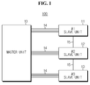
- FIG. 1 is a block diagram schematically illustrating the architecture of a communication system 100 according to an exemplary embodiment of the present disclosure.
- the communication system 100 includes a master unit 10 and a plurality of slave units 11, 12, and 13.
- FIG. 1 shows three slave units 11, 12, and 13, the number of the slave units 11, 12, and 13 according to the present disclosure may be various and the present disclosure is not limited to the disclosed embodiment.
- the master unit 10 is connected to each of the slave units 11, 12, and 13 via signal lines 14. Also, the slave units 11, 12, and 13 are connected to each other via a signal line 15.
- the signal lines 14 and 15 provide an electrical connection for data transmission and reception.
- the communication system 100 is a battery pack including secondary batteries.
- the slave units 11, 12, and 13 are connected to a plurality of secondary batteries (not shown), and each of the slave units 11, 12, and 13 includes a battery management system (BMS) (not shown) to control the charge/discharge of the secondary batteries.
- BMS battery management system
- the BMS performs various control functions applicable at the ordinary level, including measurement of electrical characteristic values including voltage or electric current, charge/discharge control, voltage equalization control, and state of charge (SOC) estimation for each of the secondary batteries.
- the slave units 11, 12, and 13 may transmit data associated with the state of the secondary batteries, for which the slave units 11, 12, and 13 are responsible, to the master unit 10, or receive a control signal related to the charge/discharge of the secondary batteries from the master unit 10, through the signal lines 14.
- the master unit 10 is shown as being connected to each of the slave units 11, 12, and 13 with three signal lines 14. In normal condition, the master unit 10 and each of the slave units 11, 12, and 13 transmit and receive data through at least two signal lines 14. In this instance, the master unit 10 and the slave units 11, 12, and 13 may use the SPI communication protocol.
- FIG. 2 is a block diagram illustrating disconnection occurred in the signal lines 14.
- the SPI communication protocol previously presented as an example needs at least two communication line including a line for data transmission and reception and a clock line.
- the universal asynchronous receiver/transmitter enables communication using a single communication line. However, even in this case, communication may be disabled due to a failure in a central processing unit (CPU), for example.
- CPU central processing unit
- each slave unit differs in timing of voltage measurement and self-diagnosis, so voltage measurement is not performed correctly or data obtained through voltage measurement is unhelpful.
- one of the problems of non-synchronization is cited as an example.
- the master unit 10 commands each of the slave units 11, 12, and 13 to measure a current voltage and transmit a voltage value with an aim of voltage equalization control. If the slave units 11, 12, and 13 are not synchronized, each of the slave units 11, 12, and 13 measures the voltage at different times, and the master unit 10 may command the voltage equalization control using voltage values measured at different times. As a result, effective voltage equalization may not be achieved. Therefore, to prevent the problem, there is a need for synchronization between units included in the communication system 100.
- the communication system 100 synchronizes units using a communication protocol ADSYNC.
- the communication system 100 may enable overlapping of communication based on a single-line communication protocol (UART communication protocol) after synchronization using ADSYNC.
- data transmission and reception may be performed using the overlapped communication protocol (UART communication protocol).
- UART communication protocol In normal condition, data communication is carried out via SPI, but when SPI communication is disenabled due to disconnection or other reasons, communication may be carried out using ADSYNC. That is, synchronization and communication is enabled via one remaining communication line. In the worst case, for example, even though communication is disenabled due to a CPU failure, synchronization may be enabled and many effects described in the foregoing may be expected.
- overlapping communication the use of a minimum width of a preset transmission preparation section and a minimum width of a preset ADSYNC cycle is cited. This method is very simple overlapping communication, and its detailed description is omitted herein.
- FIG. 3 is a waveform diagram illustrating a configuration of ADSYNC according to an exemplary embodiment of the present disclosure.
- One cycle of the ADSYNC consists of a data transmission preparation section and a data transmission section.
- the ADSYNC changes in logic level of the signal between a start point of the data transmission preparation section and a start point of the data transmission section.
- the data transmission preparation section allows output as a high logic level signal (H)
- the data transmission section allows output as a low logic level signal (L).
- the high logic level may be set to 5V and the low logic level may be set to 0V, but the present disclosure is not limited to the example. In this instance, it will be readily appreciated if the data transmission preparation section illustrated in the drawing is interpreted as a preset minimum width, and one cycle is interpreted as a minimum width of a preset ADSYNC cycle.
- the units synchronized by the ADSYNC may collect data intended to transmit, for example, data associated with voltage measurement and failure diagnosis, during the data transmission preparation section. Also, the units synchronized by the ADSYNC may transmit and receive the collected data within a preset width during the data transmission section. As shown in the example of FIG. 3 , a front part may be set for a voltage value, an intermediate part for a diagnosis value, and an end part for balancing control, etc.
- the slave units 11, 12, and 13 are all synchronized to the cycle of the ADSYNC outputted from the master unit 10.
- FIG. 4 is a block diagram illustrating that ADSYNC is outputted from the master unit 10 according to the present disclosure.
- ADSYNC is outputted from the master unit 10 through non-disconnected signal lines 14.
- the slave units 11, 12, and 13 are synchronized by the ADSYNC outputted from the master unit 10.
- FIG. 5 is a waveform diagram illustrating that ADSYNCs of the slave units 11, 12, and 13 are synchronized to ADSYNC of the master unit 10 when the ADSYNC is outputted from the master unit 10 according to the present disclosure.
- ADSYNCs of the slave units 11, 12, and 13 are synchronized to match a data transmission preparation section width and an ADSYNC cycle of the ADSYNC outputted from the master unit 10.
- the plurality of slave units 11, 12 and 13 stores a minimum width of the preset data transmission preparation section and a minimum width of the preset ADSYNC cycle. Also, the plurality of slave units 11, 12 and 13 is synchronized in association with the minimum width of the preset data transmission preparation section and the minimum width of the preset ADSYNC cycle based on the ADSYNC outputted from the master unit 10.
- the synchronization in association with the minimum width of the preset data transmission preparation section and the minimum width of the preset ADSYNC cycle may represent that a width of a data transmission preparation section of a synchronized ADSYNC is greater than the minimum width of the preset data transmission preparation section and a synchronized ADSYNC cycle is greater than the minimum width of the preset ADSYNC cycle.
- a synchronized ADSYNC cycle is greater than the minimum width of the preset ADSYNC cycle.
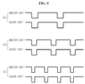
- FIG. 6 is a waveform diagram illustrating that ADSYNCs of the slave units 11, 12, and 13 are synchronized when a data transmission preparation section and an ADSYNC cycle are preset according to an exemplary embodiment of the present disclosure.
- the representation of the preset data transmission preparation section (i) and the preset ADSYNC cycle (ii) in logic level is provided. It will be readily appreciated if the data transmission preparation section illustrated in the drawing is interpreted as a preset minimum width (i) and one ADSYNC cycle is interpreted as a preset minimum width (ii).
- a width of a data transmission preparation section of ADSYNC outputted from the master unit 10 is smaller than the minimum width (i) of the preset data transmission preparation section and an ADSYNC cycle is greater than the minimum width of the ADSYNC cycle.
- the slave units 11, 12, and 13 are synchronized to ADSYNC with the same cycle width as that of the ADSYNC outputted from the master unit 10 while having the minimum width (i) of the preset data transmission preparation section.
- a width of a data transmission preparation section of ADSYNC outputted from the master unit 10 and a cycle width of the ADSYNC are all smaller than the minimum width (i) of the preset data transmission preparation section and the minimum width (ii) of the ADSYNC cycle.
- the slave units 11, 12, and 13 are synchronized to the minimum width (i) of the preset data transmission preparation section and the minimum width (ii) of the ADSYNC cycle.
- a next ADSYNC may be synchronized to a start point (point X) of the data transmission preparation section of the master unit 10 appearing subsequent to the minimum width (ii) of the preset ADSYNC cycle.
- the slave units 11, 12, and 13 are synchronized to the ADSYNC outputted from the master unit 10.
- the slave units 11, 12, and 13 are synchronized to assure the minimum width (i) of the preset data transmission preparation section and the minimum width (ii) of the preset ADSYNC cycle.
- the section (iii) as shown in (a), (b) and (c) of FIG. 6 allows data transmission and reception by data addition (overlapping).
- data addition overlapping
- ADSYNC ADSYNC
- the minimum width (i) of the preset data transmission preparation section may be variously set in consideration of an amount of data to be collected by the slave units 11, 12, and 13, the performance of the slave units 11, 12, and 13, an amount of data to be transmitted, and the communication capacity of the signal lines 14 and 15.
- the slave units 11, 12, and 13 output free-run ADSYNC.
- FIG. 7 is a block diagram illustrating that free-run ADSYNCs are outputted between the slave units 11, 12, and 13 according to an exemplary embodiment of the present disclosure.
- ADSYNC is not outputted from the master unit 10.
- the non-output of ADSYNC from the master unit 10 may imply a temporary or permanent function loss of a CPU within the master unit 10.
- the slave units 11, 12, and 13 detect the non-output of ADSYNC from the master unit 10, and output free-run ADSYNC through the signal line 15 interconnected between the slave units 11, 12, and 13.
- the free-run ADSYNC refers to a preparative signal for synchronization between the slave units 11, 12 and 13.
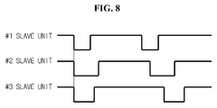
- FIG. 8 is a waveform diagram illustrating free-run ADSYNCs outputted from the slave units 11, 12, and 13 according to an exemplary embodiment of the present disclosure.
- free-run ADSYNCs outputted from the #1 slave unit 11 through the #3 slave unit 13 differ in a width of a data transmission preparation section and a width of an ADSYNC cycle.
- the free-run ADSYNCs of each of the slave units 11, 12 and 13 allow the slave units 11, 12 and 13 to detect them through the signal line 15.
- the slave units 11, 12 and 13 are synchronized to any one of the outputted free-run ADSYNCs.
- the slave units 11, 12 and 13 are synchronized to free-run ADSYNC with a smallest width of a data transmission preparation section and a smallest width of an ADSYNC cycle among the free-run ADSYNCs outputted from the plurality of slave units.
- FIG. 9 is a waveform diagram illustrating synchronized free-run ADSYNCs according to an exemplary embodiment of the present disclosure.
- FIGS. 8 and 9 it can be seen in FIG. 8 that the width of the data transmission preparation section of the #1 slave unit 11 is smallest, and one cycle of the free-run ADSYNC is earliest.
- FIG. 9 it can be seen in FIG. 9 that the free-run ADSYNCs of the #2 slave unit 12 and the #3 slave unit 13 are synchronized with the free-run ADSYNC of the #1 slave unit 11.
- the communication system 100 may be one component of a battery pack including the communication system 100 and the secondary batteries connected to the slave units 11, 12, and 13 of the communication system 100.
- BMSs may be included in the slave units to control the charge/discharge of the secondary batteries.
- the battery pack according to the present disclosure may be one component of a battery operating system including the battery pack and a load which is supplied with power from the battery pack.
- the battery operating system may include, for example, an electric vehicle (EV), a hybrid electric vehicle (HEV), an electric bike (E-Bike), a power tool, an energy storage system, an uninterruptible power supply (UPS), a portable computer, a mobile phone, a portable audio device, a portable video device, and the like, and the load may include, for example, a motor that generates a rotational force by power supplied from the battery pack, or a power inverter circuit that inverts power supplied from the battery pack to power required for various circuit components.
- EV electric vehicle
- HEV hybrid electric vehicle
- E-Bike electric bike
- UPS uninterruptible power supply
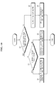
- FIG. 10 is a flowchart illustrating a method of synchronizing units in the communication system according to an exemplary embodiment of the present disclosure.
- the plurality of slave units 11, 12, and 13 determines if ADSYNC is outputted from the master unit 10, one cycle of the ADSYNC consisting of a data transmission preparation section and a data transmission section.
- ADSYNC is outputted from the master unit 10 (YES at step 10)
- a processor of the method advances to step 21.
- the processor of the method advances to step 22.
- the plurality of slave units 11, 12, and 13 outputs free-run ADSYNCs. Also, the processor of the method advances to step 23. At step 23, the plurality of slave units is synchronized to any one of the outputted free-run ADSYNCs.
- the plurality of slave units 11, 12, and 13 is synchronized to free-run ADSYNC with a smallest width of a data transmission preparation section and a smallest width of an ADSYNC cycle among the outputted free-run ADSYNCs. Then, the method is existed.
- step 20 ADSYNC is outputted from the master unit 10 (YES at step 20) and the processor of the method advances to step 21, the method is as follows.
- the plurality of slave units 11, 12, and 13 determines if a minimum width of a preset data transmission preparation section and a minimum width a preset ADSYNC cycle are stored.
- the processor of the method advances to step 24.
- the processor of the method advances to step 25.
- the plurality of slave units 11, 12, and 13 is synchronized to the cycle of the ADSYNC outputted from the master unit 10. Then, the method is existed.
- the minimum width of the preset data transmission preparation section and of the minimum width the preset ADSYNC cycle are stored in the plurality of slave units 11, 12, and 13 (YES at step 21) and the processor of the method advances to step 24, the method is as follows.
- the plurality of slave units 11, 12, and 13 is synchronized in association with the minimum width of the preset data transmission preparation section and of the minimum width the preset ADSYNC cycle based on the ADSYNC outputted from the master unit 10.
- the synchronization in association with the minimum width of the preset data transmission preparation section and of the minimum width the preset ADSYNC cycle may imply that a width of a data transmission preparation section of the synchronized ADSYNC is greater than the minimum width of the preset data transmission preparation section, and the synchronized ADSYNC cycle is greater than the minimum width of the preset ADSYNC cycle.
- the present disclosure even when a failure such as disconnection occurs in a certain signal line, data transmission and reception is enabled using the remaining signal. Also, according to another aspect of the present disclosure, through ADSYNC synchronization to free-run, various measurements and self-diagnosis may be carried out in a synchronized manner. Also, the synchronized data may be transmitted to the outside. Further, a temporary communication error may be dealt with, and a stop error in the entire system caused thereby may be prevented.
- FIGS. 1 , 2 , 4 , and 7 are distinguished logically rather than physically.
- each element corresponds to a logic element to realize the technical spirit of the present disclosure, and accordingly, even though each element is integrated or separated, it should be construed as falling within the scope of the present disclosure if a function performed by a logic element of the present disclosure can be implemented, and it should be understood that it falls within the scope of the present disclosure regardless of whether names are identical or not if it is an element performing an identical or similar function.
Landscapes
- Engineering & Computer Science (AREA)
- Power Engineering (AREA)
- Computer Networks & Wireless Communication (AREA)
- Manufacturing & Machinery (AREA)
- Chemical & Material Sciences (AREA)
- Chemical Kinetics & Catalysis (AREA)
- Electrochemistry (AREA)
- General Chemical & Material Sciences (AREA)
- Signal Processing (AREA)
- Life Sciences & Earth Sciences (AREA)
- Sustainable Development (AREA)
- Sustainable Energy (AREA)
- Transportation (AREA)
- Mechanical Engineering (AREA)
- Microelectronics & Electronic Packaging (AREA)
- Multimedia (AREA)
- Telephonic Communication Services (AREA)
- Synchronisation In Digital Transmission Systems (AREA)
- Charge And Discharge Circuits For Batteries Or The Like (AREA)
- Small-Scale Networks (AREA)
Abstract
Description
- The present disclosure relates to a communication system and a synchronization method, and more particularly, to a communication system and a synchronization method that synchronizes units included in the communication system in the event of a failure in a communication line.
- The present application claims priority to Korean Patent Application No.
10-2013-0123497 - Due to its characteristics of being easily applicable to various products and electrical characteristics such as a high energy density, a secondary battery is not only commonly applied to a portable device, but universally applied to an electric vehicle (EV) or a hybrid vehicle (HV) that is propelled by an electric motor. This secondary battery is gaining attention for its primary advantage of remarkably reducing the use of fossil fuels and not generating by-products from the use of energy, making it a new eco-friendly and energy efficient source of energy.
- A battery pack for use in electric vehicles generally has a structure consisting of a plurality of battery modules connected in series or in parallel, each battery module including a plurality of unit cells, to obtain high output. Also, the unit cell includes a positive electrode current collector and a negative electrode current collector, a separator, an active material, an electrolyte solution and a casing, and can be charged and discharged by electrochemical reactions between the components.
- Also, the battery pack generally includes a battery management system (BMS) to monitor and control the state of secondary batteries by executing an algorithm for control of power supply to a driving load such as a motor, measurement of electrical characteristic values such as current or voltage, charge/discharge control, voltage equalization control, state of charge (SOC) estimation, and the like.
- Recently, with the widespread use of a battery pack of a multi-module structure including a plurality of battery modules connected in series or in parallel, a method of integratedly controlling battery modules is used, in which a BMS is installed independently for each module and a correlation between BMSs is set on the basis of one master and multiple slaves.
- A master unit set as a master BMS communicates with each slave unit set as a slave BMS to monitor the state of all the battery modules during charging/discharging of the battery pack, to collect electrical condition information (voltage, current, and temperature) of the battery modules each slave BMS manages and to transmit a control command necessary for voltage equalization or battery system protection or data required for the slave units.
- For data transmission and reception, the master unit is connected to the slave units via communication lines, and data is transmitted and received using a communication protocol for the communication lines. As a related art, Korean Patent Application Publication No.
10-2012-0049225 - The SPI communication protocol needs at least two communication lines including a line for data transmission and reception and a clock line. Thus, when a failure such as disconnection occurs in any one of the two lines, even though the remaining communication line is in a normal connection state, data communication becomes impossible any longer.
- The universal asynchronous receiver/transmitter (UART) enables communication using a single communication line. However, even in this case, communication may be disabled due to a failure in a central processing unit (CPU), for example.
- Even though communication is disabled, if units are synchronized, voltage measurement or self-diagnosis is performed correctly and it is easy to know the content of data from the outside.
- In contrast, even when communication is enabled, if units are not synchronized, each slave unit differs in timing of voltage measurement or self-diagnosis, so voltage measurement is not performed correctly or data obtained through voltage measurement may be unhelpful.
- Accordingly, there is a need for a method that enables all units included in a communication system to do synchronized activities and perform data transmission and reception.
- The present disclosure is designed to solve the problem of the related art, and therefore, the present disclosure is directed to providing a communication system and a synchronization method that synchronizes units included in the communication system in the event of a failure in a communication line.
- To achieve the object, a communication system according to the present disclosure includes a plurality of slave units in which adjacent slave units are connected via a signal line, and a master unit connected to the plurality slave units via a signal line, wherein when ADSYNC is outputted from the master unit, the slave units are all synchronized to a cycle of the ADSYNC outputted from the master unit, one cycle of the ADSYNC composed of a data transmission preparation section and a data transmission section, when ADSYNC is not outputted from the master unit, the slave units output free-run ADSYNCs, and when the free-run ADSYNCs are outputted from the plurality slave units, the slave units are synchronized to any one of the outputted free-run ADSYNCs.
- According to one embodiment of the present disclosure, the ADSYNC may change in logic level of a signal between the data transmission preparation section and a start point of the data transmission section.
- In this case, the slave units may be synchronized to free-run ADSYNC with a smallest width of a data transmission preparation section and a smallest width of an ADSYNC cycle among the free-run ADSYNCs outputted from the plurality of slave units.
- According to one embodiment of the present disclosure, the plurality of slave units may store a minimum width of a preset data transmission preparation section. In this case, a minimum width of a preset ADSYNC cycle, and the plurality of slave units may be synchronized in association with the minimum width of the preset data transmission preparation section and the minimum width of the preset ADSYNC cycle based on the ADSYNC outputted from the master unit.
- The synchronization in association with the minimum width of the preset data transmission preparation section and the minimum width of the preset ADSYNC cycle may represent that a width of a data transmission preparation section of a synchronized ADSYNC is greater than the minimum width of the preset data transmission preparation section and a synchronized ADSYNC cycle is greater than the minimum width of the preset ADSYNC cycle.
- The communication system according to the present disclosure may be one element of a battery pack including the communication system and secondary batteries connected to the slave units of the communication system. In this instance, the slave units may include battery management systems to control the charge and discharge of the secondary batteries.
- The battery pack according to the present disclosure may be one element of a battery operating system including the battery pack and a load which is supplied with power from the battery pack.
- To achieve the object, a method of synchronizing units in a communication system according to the present disclosure corresponds to a method of synchronizing slave units in a communication system including a plurality of slave units in which adjacent slave units are connected via a signal line, and a master unit connected to the plurality slave units via a signal line, and the method includes (a) synchronizing all the slave units to a cycle of ADSYNC outputted from the master unit when the ADSYNC is outputted from the master unit, one cycle of the ADSYNC composed of a data transmission preparation section and a data transmission section, (b) outputting free-run ADSYNCs from the slave units when ADSYNC is not outputted from the master unit, and (c) synchronizing the slave units to any one free-run ADSYNC among the free-run ADSYNCs outputted from the plurality of slave units when the free-run ADSYNCs are outputted from the plurality slave units.
- According to one embodiment of the present disclosure, the step (c) may include synchronizing the slave units to free-run ADSYNC with a smallest width of a data transmission preparation section and a smallest width of an ADSYNC cycle among the free-run ADSYNCs outputted from the plurality of slave units.
- According to one embodiment of the present disclosure, the plurality of slave units may store a minimum width of a preset data transmission preparation section and a minimum width of a preset ADSYNC cycle, and the step (a) may include synchronizing the plurality of slave units in association with the minimum width of the preset data transmission preparation section and the minimum width of the preset ADSYNC cycle based on the ADSYNC outputted from the master unit.
- The synchronizing in association with the minimum width of the preset data transmission preparation section and the minimum width of the preset ADSYNC cycle in the step (a) may represent that a width of a data transmission preparation section of a synchronized ADSYNC is greater than the minimum width of the preset data transmission preparation section and a synchronized ADSYNC cycle is greater than the minimum width of the preset ADSYNC cycle.
- According to one aspect of the present disclosure, even when a failure such as disconnection occurs in a certain signal line, data transmission and reception is enabled using the remaining signal line.
- According to another aspect of the present disclosure, by synchronizing ADSYNC in a free-run mode, various measurements and self-diagnosis may be carried out in a synchronized manner. Also, the synchronized data may be transmitted to the outside.
- According to still another aspect of the present disclosure, a temporary communication error may be dealt with, and a stop error in the entire system caused thereby may be prevented.
- The accompanying drawing illustrates a preferred embodiment of the present disclosure and together with the foregoing disclosure, serves to provide further understanding of the technical spirit of the present disclosure, and thus, the present disclosure is not construed as being limited to the drawing.
-
FIG. 1 is a block diagram schematically illustrating the architecture of a communication system according to an exemplary embodiment of the present disclosure. -
FIG. 2 is a block diagram illustrating disconnection occurred in signal lines. -
FIG. 3 is a waveform diagram illustrating a configuration of ADSYNC according to an exemplary embodiment of the present disclosure. -
FIG. 4 is a block diagram illustrating that ADSYNC is outputted from a master unit according to the present disclosure. -
FIG. 5 is a waveform diagram illustrating that ADSYNCs of slave units are synchronized to ADSYNC of a master unit when the ADSYNC is outputted from the master unit according to the present disclosure. -
FIG. 6 is a waveform diagram illustrating that ADSYNCs of slave units are synchronized when a data transmission preparation section and an ADSYNC cycle are preset according to an exemplary embodiment of the present disclosure. -
FIG. 7 is a block diagram illustrating that free-run ADSYNCs are outputted between slave units according to an exemplary embodiment of the present disclosure. -
FIG. 8 is a waveform diagram illustrating free-run ADSYNCs outputted from slave units according to an exemplary embodiment of the present disclosure. -
FIG. 9 is a waveform diagram illustrating synchronized free-run ADSYNCs according to an exemplary embodiment of the present disclosure. -
FIG. 10 is a flowchart illustrating a method of synchronizing units in a communication system according to an exemplary embodiment of the present disclosure. - Hereinafter, preferred embodiments of the present disclosure will be described in detail with reference to the accompanying drawings. Prior to the description, it should be understood that the terms used in the specification and the appended claims should not be construed as limited to general and dictionary meanings, but interpreted based on the meanings and concepts corresponding to technical aspects of the present disclosure on the basis of the principle that the inventor is allowed to define terms appropriately for the best explanation. Therefore, the description proposed herein is just a preferable example for the purpose of illustrations only, not intended to limit the scope of the disclosure, so it should be understood that other equivalents and modifications could be made thereto without departing from the spirit and scope of the disclosure.
-
FIG. 1 is a block diagram schematically illustrating the architecture of acommunication system 100 according to an exemplary embodiment of the present disclosure. - Referring to
FIG. 1 , thecommunication system 100 according to the present disclosure includes amaster unit 10 and a plurality ofslave units FIG. 1 shows threeslave units slave units - The
master unit 10 is connected to each of theslave units signal lines 14. Also, theslave units signal line 15. Thesignal lines - For the convenience of description, assume the
communication system 100 according to the present disclosure is a battery pack including secondary batteries. Theslave units slave units slave units slave units master unit 10, or receive a control signal related to the charge/discharge of the secondary batteries from themaster unit 10, through the signal lines 14. - Referring to
FIG. 1 , themaster unit 10 is shown as being connected to each of theslave units signal lines 14. In normal condition, themaster unit 10 and each of theslave units signal lines 14. In this instance, themaster unit 10 and theslave units -
FIG. 2 is a block diagram illustrating disconnection occurred in the signal lines 14. - Referring to
FIG. 2 , two of the three signal lines connected between themaster unit 10 and each of theslave units - The universal asynchronous receiver/transmitter (UART) enables communication using a single communication line. However, even in this case, communication may be disabled due to a failure in a central processing unit (CPU), for example.
- Even though communication is disabled, if units are synchronized, voltage measurement or self-diagnosis is performed correctly and it is easy to know the content of data from the outside.
- In contrast, even when communication is enabled, if units are not synchronized, each slave unit differs in timing of voltage measurement and self-diagnosis, so voltage measurement is not performed correctly or data obtained through voltage measurement is unhelpful. Hereinafter, one of the problems of non-synchronization is cited as an example.
- For example, assume the
master unit 10 commands each of theslave units slave units slave units master unit 10 may command the voltage equalization control using voltage values measured at different times. As a result, effective voltage equalization may not be achieved. Therefore, to prevent the problem, there is a need for synchronization between units included in thecommunication system 100. - The
communication system 100 according to the present disclosure synchronizes units using a communication protocol ADSYNC. - Also, the
communication system 100 according to the present disclosure may enable overlapping of communication based on a single-line communication protocol (UART communication protocol) after synchronization using ADSYNC. Also, data transmission and reception may be performed using the overlapped communication protocol (UART communication protocol). In normal condition, data communication is carried out via SPI, but when SPI communication is disenabled due to disconnection or other reasons, communication may be carried out using ADSYNC. That is, synchronization and communication is enabled via one remaining communication line. In the worst case, for example, even though communication is disenabled due to a CPU failure, synchronization may be enabled and many effects described in the foregoing may be expected. As an example of overlapping communication, the use of a minimum width of a preset transmission preparation section and a minimum width of a preset ADSYNC cycle is cited. This method is very simple overlapping communication, and its detailed description is omitted herein. -
FIG. 3 is a waveform diagram illustrating a configuration of ADSYNC according to an exemplary embodiment of the present disclosure. - One cycle of the ADSYNC consists of a data transmission preparation section and a data transmission section. To distinguish the data transmission preparation section from the data transmission section, the ADSYNC changes in logic level of the signal between a start point of the data transmission preparation section and a start point of the data transmission section. According to an exemplary embodiment of the present disclosure, the data transmission preparation section allows output as a high logic level signal (H), and the data transmission section allows output as a low logic level signal (L). The high logic level may be set to 5V and the low logic level may be set to 0V, but the present disclosure is not limited to the example. In this instance, it will be readily appreciated if the data transmission preparation section illustrated in the drawing is interpreted as a preset minimum width, and one cycle is interpreted as a minimum width of a preset ADSYNC cycle.
- The units synchronized by the ADSYNC may collect data intended to transmit, for example, data associated with voltage measurement and failure diagnosis, during the data transmission preparation section. Also, the units synchronized by the ADSYNC may transmit and receive the collected data within a preset width during the data transmission section. As shown in the example of
FIG. 3 , a front part may be set for a voltage value, an intermediate part for a diagnosis value, and an end part for balancing control, etc. - Here, the ADSYNC cycle presented as below refers to one cycle of the signal composed of the data transmission preparation section and the data transmission section (ADSYNC cycle = data transmission preparation section + data transmission section).
- According to the present disclosure, when ADSYNC is outputted from the
master unit 10, theslave units master unit 10. -
FIG. 4 is a block diagram illustrating that ADSYNC is outputted from themaster unit 10 according to the present disclosure. - Referring to
FIG. 4 , it can be seen that ADSYNC is outputted from themaster unit 10 through non-disconnected signal lines 14. As shown inFIG. 4 , when any one of thesignal lines 14 connected between themaster unit 10 and theslave units master unit 10 normally works, theslave units master unit 10. -
FIG. 5 is a waveform diagram illustrating that ADSYNCs of theslave units master unit 10 when the ADSYNC is outputted from themaster unit 10 according to the present disclosure. - Referring to (a) through (c) of
FIG. 5 , it can be seen that ADSYNCs of theslave units master unit 10. - According to an exemplary embodiment of the present disclosure, the plurality of
slave units slave units master unit 10. - The synchronization in association with the minimum width of the preset data transmission preparation section and the minimum width of the preset ADSYNC cycle may represent that a width of a data transmission preparation section of a synchronized ADSYNC is greater than the minimum width of the preset data transmission preparation section and a synchronized ADSYNC cycle is greater than the minimum width of the preset ADSYNC cycle. For convenience of understanding, its description is provided with reference to
FIG. 6 . -
FIG. 6 is a waveform diagram illustrating that ADSYNCs of theslave units - First, on the top of
FIG. 6 , the representation of the preset data transmission preparation section (i) and the preset ADSYNC cycle (ii) in logic level is provided. It will be readily appreciated if the data transmission preparation section illustrated in the drawing is interpreted as a preset minimum width (i) and one ADSYNC cycle is interpreted as a preset minimum width (ii). - Subsequently, seeing (a) of
FIG. 6 , it is found that a data transmission preparation section and an ADSYNC cycle of ADSYNC outputted from themaster unit 10 are greater than the minimum width (i) of the preset data transmission preparation section and the minimum width (ii) of the preset ADSYNC cycle. Thus, theslave units master unit 10. - Subsequently, seeing (b) of
FIG. 6 , it is found that a width of a data transmission preparation section of ADSYNC outputted from themaster unit 10 is smaller than the minimum width (i) of the preset data transmission preparation section and an ADSYNC cycle is greater than the minimum width of the ADSYNC cycle. In this case, theslave units master unit 10 while having the minimum width (i) of the preset data transmission preparation section. - Subsequently, seeing (c) of
FIG. 6 , it is found that a width of a data transmission preparation section of ADSYNC outputted from themaster unit 10 and a cycle width of the ADSYNC are all smaller than the minimum width (i) of the preset data transmission preparation section and the minimum width (ii) of the ADSYNC cycle. In this case, theslave units master unit 10 appearing subsequent to the minimum width (ii) of the preset ADSYNC cycle. - That is, when the width of the data transmission preparation section and the width of the ADSYNC cycle of the ADSYNC outputted from the
master unit 10 are greater than the minimum width (i) of the preset data transmission preparation section and the minimum width (ii) of the preset ADSYNC cycle, theslave units master unit 10. In contrast, when the width of the data transmission preparation section and the width of the ADSYNC cycle of the ADSYNC outputted from themaster unit 10 are smaller than the minimum width (i) of the preset data transmission preparation section and the minimum width (ii) of the preset ADSYNC cycle, theslave units - In this instance, the section (iii) as shown in (a), (b) and (c) of
FIG. 6 allows data transmission and reception by data addition (overlapping). However, even though multiple waveforms are added in the section (iii), it does not influence ADSYNC, so communication waveforms may overlap. Thus, during the section (iii), data transmission and reception is enabled by adding (overlapping) a signal in accordance with UART or other communication protocols. - The minimum width (i) of the preset data transmission preparation section may be variously set in consideration of an amount of data to be collected by the
slave units slave units signal lines - According to the present disclosure, when ADSYNC is not outputted from the
master unit 10, theslave units -
FIG. 7 is a block diagram illustrating that free-run ADSYNCs are outputted between theslave units - Referring to
FIG. 7 , this is the case in which ADSYNC is not outputted from themaster unit 10. The non-output of ADSYNC from themaster unit 10 may imply a temporary or permanent function loss of a CPU within themaster unit 10. In this case, theslave units master unit 10, and output free-run ADSYNC through thesignal line 15 interconnected between theslave units slave units -
FIG. 8 is a waveform diagram illustrating free-run ADSYNCs outputted from theslave units - Referring to
FIG. 8 , it can be seen that free-run ADSYNCs outputted from the #1slave unit 11 through the #3slave unit 13 differ in a width of a data transmission preparation section and a width of an ADSYNC cycle. The free-run ADSYNCs of each of theslave units slave units signal line 15. - In this instance, the
slave units - According to an exemplary embodiment of the present disclosure, the
slave units -
FIG. 9 is a waveform diagram illustrating synchronized free-run ADSYNCs according to an exemplary embodiment of the present disclosure. - Referring to
FIGS. 8 and9 together, it can be seen inFIG. 8 that the width of the data transmission preparation section of the #1slave unit 11 is smallest, and one cycle of the free-run ADSYNC is earliest. Thus, according to an exemplary embodiment of the present disclosure, it can be seen inFIG. 9 that the free-run ADSYNCs of the #2slave unit 12 and the #3slave unit 13 are synchronized with the free-run ADSYNC of the #1slave unit 11. - The
communication system 100 according to the present disclosure may be one component of a battery pack including thecommunication system 100 and the secondary batteries connected to theslave units communication system 100. In this instance, BMSs may be included in the slave units to control the charge/discharge of the secondary batteries. - The battery pack according to the present disclosure may be one component of a battery operating system including the battery pack and a load which is supplied with power from the battery pack.
- The battery operating system may include, for example, an electric vehicle (EV), a hybrid electric vehicle (HEV), an electric bike (E-Bike), a power tool, an energy storage system, an uninterruptible power supply (UPS), a portable computer, a mobile phone, a portable audio device, a portable video device, and the like, and the load may include, for example, a motor that generates a rotational force by power supplied from the battery pack, or a power inverter circuit that inverts power supplied from the battery pack to power required for various circuit components.
- Hereinafter, a method of synchronizing units in the
communication system 100 is described. However, in the description of the method according to the present disclosure, because the architecture of thecommunication system 100 has been described in detail, an overlapping description is omitted herein. -
FIG. 10 is a flowchart illustrating a method of synchronizing units in the communication system according to an exemplary embodiment of the present disclosure. - First, at
step 20, the plurality ofslave units master unit 10, one cycle of the ADSYNC consisting of a data transmission preparation section and a data transmission section. When ADSYNC is outputted from the master unit 10 (YES at step 10), a processor of the method advances to step 21. In contrast, when ADSYNC is not outputted from the master unit 10 (NO at step 10), the processor of the method advances to step 22. - At
step 22, the plurality ofslave units step 23, the plurality of slave units is synchronized to any one of the outputted free-run ADSYNCs. - According to an exemplary embodiment of the present disclosure, the plurality of
slave units - When at
step 20, ADSYNC is outputted from the master unit 10 (YES at step 20) and the processor of the method advances to step 21, the method is as follows. - At
step 21, the plurality ofslave units slave units slave units - At
step 22, the plurality ofslave units master unit 10. Then, the method is existed. - When at
step 21, the minimum width of the preset data transmission preparation section and of the minimum width the preset ADSYNC cycle are stored in the plurality ofslave units - At
step 24, the plurality ofslave units master unit 10. - According to an exemplary embodiment of the present disclosure, the synchronization in association with the minimum width of the preset data transmission preparation section and of the minimum width the preset ADSYNC cycle may imply that a width of a data transmission preparation section of the synchronized ADSYNC is greater than the minimum width of the preset data transmission preparation section, and the synchronized ADSYNC cycle is greater than the minimum width of the preset ADSYNC cycle.
- According to the present disclosure, even when a failure such as disconnection occurs in a certain signal line, data transmission and reception is enabled using the remaining signal. Also, according to another aspect of the present disclosure, through ADSYNC synchronization to free-run, various measurements and self-diagnosis may be carried out in a synchronized manner. Also, the synchronized data may be transmitted to the outside. Further, a temporary communication error may be dealt with, and a stop error in the entire system caused thereby may be prevented.
- In the description of the present disclosure, it should be understood that each element of the present disclosure shown in
FIGS. 1 ,2 ,4 , and7 is distinguished logically rather than physically. - That is, each element corresponds to a logic element to realize the technical spirit of the present disclosure, and accordingly, even though each element is integrated or separated, it should be construed as falling within the scope of the present disclosure if a function performed by a logic element of the present disclosure can be implemented, and it should be understood that it falls within the scope of the present disclosure regardless of whether names are identical or not if it is an element performing an identical or similar function.
- While the present disclosure has been hereinabove described in connection with only a limited number of embodiments and drawings, the present disclosure is not limited thereto and it should be understood that various changes and modifications may be made by an ordinary person skilled in the art within the spirit and scope of the disclosure and the appended claims and their equivalents.
Claims (14)
- A communication system comprising:a plurality of slave units in which adjacent slave units are connected via a signal line; anda master unit connected to the plurality slave units via a signal line,wherein when ADSYNC is outputted from the master unit, the slave units are all synchronized to a cycle of the ADSYNC outputted from the master unit, one cycle of the ADSYNC composed of a data transmission preparation section and a data transmission section,when ADSYNC is not outputted from the master unit, the slave units output free-run ADSYNCs, andwhen the free-run ADSYNCs are outputted from the plurality slave units, the slave units are synchronized to any one of the outputted free-run ADSYNCs.
- The communication system according to claim 1, wherein the ADSYNC changes in logic level of a signal between the data transmission preparation section and a start point of the data transmission section.
- The communication system according to claim 2, wherein the slave units are synchronized to free-run ADSYNC with a smallest width of a data transmission preparation section and a smallest width of an ADSYNC cycle among the free-run ADSYNCs outputted from the plurality of slave units.
- The communication system according to claim 1, wherein the plurality of slave units stores a minimum width of a preset data transmission preparation section and a minimum width of a preset ADSYNC cycle, and the plurality of slave units is synchronized in association with the minimum width of the preset data transmission preparation section and the minimum width of the preset ADSYNC cycle based on the ADSYNC outputted from the master unit.
- The communication system according to claim 4, wherein the synchronization in association with the minimum width of the preset data transmission preparation section and the minimum width of the preset ADSYNC cycle represents that a width of a data transmission preparation section of a synchronized ADSYNC is greater than the minimum width of the preset data transmission preparation section and a synchronized ADSYNC cycle is greater than the minimum width of the preset ADSYNC cycle.
- The communication system according to claim 1, wherein data transmission is performed by overlapping a communication protocol other than ADSYNC in the data transmission section.
- A battery pack comprising:a communication system according to any one of claims 1 through 6; andsecondary batteries connected to the slave units of the communication system,wherein the slave units comprise battery management systems to control the charge and discharge of the secondary batteries.
- A battery operating system comprising:a battery pack according to claim 7; anda load which is supplied with power from the battery pack.
- A method of synchronizing units in a communication system, the communication system comprising a plurality of slave units in which adjacent slave units are connected via a signal line, and a master unit connected to the plurality slave units via a signal line, to synchronize the slave units, the method comprising:(a) synchronizing all the slave units to a cycle of ADSYNC outputted from the master unit when the ADSYNC is outputted from the master unit, one cycle of the ADSYNC composed of a data transmission preparation section and a data transmission section;(b) outputting free-run ADSYNCs from the slave units when ADSYNC is not outputted from the master unit; and(c) synchronizing the slave units to any one free-run ADSYNC among the free-run ADSYNCs outputted from the plurality of slave units when the free-run ADSYNCs are outputted from the plurality slave units.
- The method of synchronizing units in a communication system according to claim 9, wherein the ADSYNC changes in logic level of a signal between the data transmission preparation section and a start point of the data transmission section.
- The method of synchronizing units in a communication system according to claim 10, wherein the step (c) comprises synchronizing the slave units to free-run ADSYNC with a smallest width of a data transmission preparation section and a smallest width of an ADSYNC cycle among the free-run ADSYNCs outputted from the plurality of slave units.
- The method of synchronizing units in a communication system according to claim 9, wherein the plurality of slave units stores a minimum width of a preset data transmission preparation section and a minimum width of a preset ADSYNC cycle, and
the step (a) comprises synchronizing the plurality of slave units in association with the minimum width of the preset data transmission preparation section and the minimum width of the preset ADSYNC cycle based on the ADSYNC outputted from the master unit. - The method of synchronizing units in a communication system according to claim 12, wherein the synchronizing in association with the minimum width of the preset data transmission preparation section and the minimum width of the preset ADSYNC cycle in the step (a) represents that a width of a data transmission preparation section of a synchronized ADSYNC is greater than the minimum width of the preset data transmission preparation section and a synchronized ADSYNC cycle is greater than the minimum width of the preset ADSYNC cycle.
- The method of synchronizing units in a communication system according to claim 9, further comprising:(d) transmitting data by overlapping a communication protocol other than ADSYNC in the data transmission section.
Applications Claiming Priority (2)
| Application Number | Priority Date | Filing Date | Title |
|---|---|---|---|
| KR1020130123497A KR101640888B1 (en) | 2013-10-16 | 2013-10-16 | Communication system having synchronised units and synchronising method thereof |
| PCT/KR2014/009746 WO2015056999A1 (en) | 2013-10-16 | 2014-10-16 | Communication system having synchronized units and synchronization method for units |
Publications (3)
| Publication Number | Publication Date |
|---|---|
| EP3024166A1 true EP3024166A1 (en) | 2016-05-25 |
| EP3024166A4 EP3024166A4 (en) | 2017-03-15 |
| EP3024166B1 EP3024166B1 (en) | 2018-04-04 |
Family
ID=52828373
Family Applications (1)
| Application Number | Title | Priority Date | Filing Date |
|---|---|---|---|
| EP14854009.9A Active EP3024166B1 (en) | 2013-10-16 | 2014-10-16 | Communication system having synchronized units and synchronization method for units |
Country Status (6)
| Country | Link |
|---|---|
| US (1) | US9705663B2 (en) |
| EP (1) | EP3024166B1 (en) |
| JP (1) | JP6296577B2 (en) |
| KR (1) | KR101640888B1 (en) |
| CN (1) | CN105474572B (en) |
| WO (1) | WO2015056999A1 (en) |
Families Citing this family (9)
| Publication number | Priority date | Publication date | Assignee | Title |
|---|---|---|---|---|
| JP6157536B2 (en) * | 2015-04-30 | 2017-07-05 | ヤマハ発動機株式会社 | Saddle-type electric vehicle and charging system for saddle-type electric vehicle |
| CN106569424B (en) * | 2016-11-03 | 2019-06-28 | 上海理工大学 | The on-line synchronous method of battery management system data storage |
| JP6838395B2 (en) * | 2016-12-27 | 2021-03-03 | 株式会社ジェイテクト | Steering control device |
| JP6812788B2 (en) * | 2016-12-27 | 2021-01-13 | 株式会社ジェイテクト | Steering control device |
| KR102680803B1 (en) * | 2019-06-18 | 2024-07-04 | 주식회사 엘지에너지솔루션 | Battery management system and method |
| WO2021131582A1 (en) * | 2019-12-25 | 2021-07-01 | ソニーセミコンダクタソリューションズ株式会社 | Synchronization device and synchronization method |
| DE102020107783A1 (en) * | 2020-03-20 | 2021-09-23 | Beckhoff Automation Gmbh | Data transfer in a linear transport system |
| KR102897429B1 (en) * | 2020-06-30 | 2025-12-08 | 주식회사 엘지에너지솔루션 | Battery management system and communication method thereof |
| KR20240038902A (en) * | 2022-09-16 | 2024-03-26 | 주식회사 엘지에너지솔루션 | Battery pack for generating synchronization signal and vehicle including the same |
Family Cites Families (20)
| Publication number | Priority date | Publication date | Assignee | Title |
|---|---|---|---|---|
| JP2588290B2 (en) * | 1989-12-28 | 1997-03-05 | 株式会社東芝 | Data input / output system |
| US5577075A (en) * | 1991-09-26 | 1996-11-19 | Ipc Information Systems, Inc. | Distributed clocking system |
| JP2001244918A (en) * | 2000-02-28 | 2001-09-07 | Fujitsu Ltd | Network equipment |
| JP2002055181A (en) * | 2000-08-09 | 2002-02-20 | Nissin Electric Co Ltd | Time piece synchronous circuit |
| JP2002077423A (en) * | 2000-08-30 | 2002-03-15 | Matsushita Electric Ind Co Ltd | Master / slave operation switching device for intercom system |
| JP4582932B2 (en) * | 2001-02-26 | 2010-11-17 | Okiセミコンダクタ株式会社 | Synchronous correction circuit |
| US7506179B2 (en) * | 2003-04-11 | 2009-03-17 | Zilker Labs, Inc. | Method and apparatus for improved DC power delivery management and configuration |
| US7793005B1 (en) * | 2003-04-11 | 2010-09-07 | Zilker Labs, Inc. | Power management system using a multi-master multi-slave bus and multi-function point-of-load regulators |
| CN101088203B (en) * | 2004-12-24 | 2010-08-18 | Lg化学株式会社 | System and method for controlling voltage balance in a battery pack having multiple lithium-ion cells |
| US7518894B2 (en) * | 2005-03-31 | 2009-04-14 | Silicon Laboratories Inc. | Distributed power supply system having reassignable master |
| JP2007281800A (en) * | 2006-04-05 | 2007-10-25 | Kenwood Corp | Automatic synchronization signal switching device and its method |
| CN101478846A (en) * | 2008-12-31 | 2009-07-08 | 上海广茂达灯光景观工程有限公司 | LED lamp light controlling bus and controlling method thereof |
| KR101016813B1 (en) | 2009-05-19 | 2011-02-21 | 에스비리모티브 주식회사 | Battery Management System and Its Driving Method |
| US9035610B2 (en) | 2009-06-10 | 2015-05-19 | A123 Systems Llc | System and method for controlling output of a battery pack |
| US20120128372A1 (en) | 2009-08-03 | 2012-05-24 | Mitsubishi Electric Corporation | Optical line termination, pon system, and data reception processing method |
| KR20110051093A (en) * | 2009-11-09 | 2011-05-17 | 삼성전자주식회사 | Apparatus and Method for Synchronization Between Nodes in Time Division Duplex Networks |
| KR101861723B1 (en) * | 2011-12-20 | 2018-05-30 | 삼성전자주식회사 | Devices and method of adjusting synchronization signal preventing tearing and flicker |
| JP5877310B2 (en) * | 2011-12-28 | 2016-03-08 | パナソニックIpマネジメント株式会社 | Master / slave synchronous communication system |
| WO2014070831A1 (en) * | 2012-10-30 | 2014-05-08 | Board Of Trustees Of The University Of Alabama | Distributed battery power electronics architecture and control |
| KR102201102B1 (en) * | 2013-03-15 | 2021-01-12 | 디자인 플럭스 테크놀로지스, 엘엘씨 | Method and apparatus for creating a dynamically reconfigurable energy storage device |
-
2013
- 2013-10-16 KR KR1020130123497A patent/KR101640888B1/en active Active
-
2014
- 2014-10-16 EP EP14854009.9A patent/EP3024166B1/en active Active
- 2014-10-16 WO PCT/KR2014/009746 patent/WO2015056999A1/en not_active Ceased
- 2014-10-16 JP JP2016523908A patent/JP6296577B2/en active Active
- 2014-10-16 US US14/906,734 patent/US9705663B2/en active Active
- 2014-10-16 CN CN201480046071.3A patent/CN105474572B/en active Active
Also Published As
| Publication number | Publication date |
|---|---|
| CN105474572B (en) | 2018-10-12 |
| KR101640888B1 (en) | 2016-07-19 |
| WO2015056999A1 (en) | 2015-04-23 |
| EP3024166A4 (en) | 2017-03-15 |
| JP2016540412A (en) | 2016-12-22 |
| JP6296577B2 (en) | 2018-03-20 |
| US9705663B2 (en) | 2017-07-11 |
| KR20150044283A (en) | 2015-04-24 |
| EP3024166B1 (en) | 2018-04-04 |
| CN105474572A (en) | 2016-04-06 |
| US20160164662A1 (en) | 2016-06-09 |
Similar Documents
| Publication | Publication Date | Title |
|---|---|---|
| EP3024166B1 (en) | Communication system having synchronized units and synchronization method for units | |
| EP3477814B1 (en) | Communication method between master controller and slave controller, slave controller for the same, and battery management system using the same | |
| EP2928042B1 (en) | Battery management system capable of transmitting secondary protection signal and diagnostic signal using few insulation elements | |
| EP2725686A1 (en) | System and method for allocating identifier to multi-bms | |
| EP3096431B1 (en) | Battery management unit and method for setting identifier by using frequency modulation | |
| KR101613230B1 (en) | Wired communication unit changing communication protocol when malfunction has occurred in the communication line and wired communication system including thereof | |
| EP2988190B1 (en) | Communication terminal for constructing daisy chain communication network without distinction between input connector and output connector | |
| EP3576211A1 (en) | Method and system for managing battery pack | |
| KR20150048005A (en) | Battery management system sending 2nd protection and dignosis signal using fewer isolation devices | |
| KR20150007052A (en) | Microprocessor changing communication protocol when malfunction has occurred in the communication line and communication system including thereof | |
| KR20150048006A (en) | Battery management system sending 2nd protection and dignosis signal using fewer isolation devices |
Legal Events
| Date | Code | Title | Description |
|---|---|---|---|
| PUAI | Public reference made under article 153(3) epc to a published international application that has entered the european phase |
Free format text: ORIGINAL CODE: 0009012 |
|
| 17P | Request for examination filed |
Effective date: 20160215 |
|
| AK | Designated contracting states |
Kind code of ref document: A1 Designated state(s): AL AT BE BG CH CY CZ DE DK EE ES FI FR GB GR HR HU IE IS IT LI LT LU LV MC MK MT NL NO PL PT RO RS SE SI SK SM TR |
|
| AX | Request for extension of the european patent |
Extension state: BA ME |
|
| DAX | Request for extension of the european patent (deleted) | ||
| RIC1 | Information provided on ipc code assigned before grant |
Ipc: H04L 29/02 20060101ALI20170202BHEP Ipc: H01M 10/44 20060101ALI20170202BHEP Ipc: H04L 7/00 20060101AFI20170202BHEP Ipc: H04Q 9/04 20060101ALI20170202BHEP |
|
| A4 | Supplementary search report drawn up and despatched |
Effective date: 20170209 |
|
| GRAP | Despatch of communication of intention to grant a patent |
Free format text: ORIGINAL CODE: EPIDOSNIGR1 |
|
| STAA | Information on the status of an ep patent application or granted ep patent |
Free format text: STATUS: GRANT OF PATENT IS INTENDED |
|
| INTG | Intention to grant announced |
Effective date: 20171215 |
|
| GRAS | Grant fee paid |
Free format text: ORIGINAL CODE: EPIDOSNIGR3 |
|
| GRAA | (expected) grant |
Free format text: ORIGINAL CODE: 0009210 |
|
| STAA | Information on the status of an ep patent application or granted ep patent |
Free format text: STATUS: THE PATENT HAS BEEN GRANTED |
|
| AK | Designated contracting states |
Kind code of ref document: B1 Designated state(s): AL AT BE BG CH CY CZ DE DK EE ES FI FR GB GR HR HU IE IS IT LI LT LU LV MC MK MT NL NO PL PT RO RS SE SI SK SM TR |
|
| REG | Reference to a national code |
Ref country code: GB Ref legal event code: FG4D |
|
| REG | Reference to a national code |
Ref country code: CH Ref legal event code: EP |
|
| REG | Reference to a national code |
Ref country code: AT Ref legal event code: REF Ref document number: 986708 Country of ref document: AT Kind code of ref document: T Effective date: 20180415 |
|
| REG | Reference to a national code |
Ref country code: IE Ref legal event code: FG4D |
|
| REG | Reference to a national code |
Ref country code: DE Ref legal event code: R096 Ref document number: 602014023518 Country of ref document: DE |
|
| REG | Reference to a national code |
Ref country code: NL Ref legal event code: MP Effective date: 20180404 |
|
| REG | Reference to a national code |
Ref country code: LT Ref legal event code: MG4D |
|
| REG | Reference to a national code |
Ref country code: FR Ref legal event code: PLFP Year of fee payment: 5 |
|
| PG25 | Lapsed in a contracting state [announced via postgrant information from national office to epo] |
Ref country code: NL Free format text: LAPSE BECAUSE OF FAILURE TO SUBMIT A TRANSLATION OF THE DESCRIPTION OR TO PAY THE FEE WITHIN THE PRESCRIBED TIME-LIMIT Effective date: 20180404 |
|
| PG25 | Lapsed in a contracting state [announced via postgrant information from national office to epo] |
Ref country code: NO Free format text: LAPSE BECAUSE OF FAILURE TO SUBMIT A TRANSLATION OF THE DESCRIPTION OR TO PAY THE FEE WITHIN THE PRESCRIBED TIME-LIMIT Effective date: 20180704 Ref country code: AL Free format text: LAPSE BECAUSE OF FAILURE TO SUBMIT A TRANSLATION OF THE DESCRIPTION OR TO PAY THE FEE WITHIN THE PRESCRIBED TIME-LIMIT Effective date: 20180404 Ref country code: FI Free format text: LAPSE BECAUSE OF FAILURE TO SUBMIT A TRANSLATION OF THE DESCRIPTION OR TO PAY THE FEE WITHIN THE PRESCRIBED TIME-LIMIT Effective date: 20180404 Ref country code: BG Free format text: LAPSE BECAUSE OF FAILURE TO SUBMIT A TRANSLATION OF THE DESCRIPTION OR TO PAY THE FEE WITHIN THE PRESCRIBED TIME-LIMIT Effective date: 20180704 Ref country code: SE Free format text: LAPSE BECAUSE OF FAILURE TO SUBMIT A TRANSLATION OF THE DESCRIPTION OR TO PAY THE FEE WITHIN THE PRESCRIBED TIME-LIMIT Effective date: 20180404 Ref country code: PL Free format text: LAPSE BECAUSE OF FAILURE TO SUBMIT A TRANSLATION OF THE DESCRIPTION OR TO PAY THE FEE WITHIN THE PRESCRIBED TIME-LIMIT Effective date: 20180404 Ref country code: ES Free format text: LAPSE BECAUSE OF FAILURE TO SUBMIT A TRANSLATION OF THE DESCRIPTION OR TO PAY THE FEE WITHIN THE PRESCRIBED TIME-LIMIT Effective date: 20180404 Ref country code: LT Free format text: LAPSE BECAUSE OF FAILURE TO SUBMIT A TRANSLATION OF THE DESCRIPTION OR TO PAY THE FEE WITHIN THE PRESCRIBED TIME-LIMIT Effective date: 20180404 |
|
| PG25 | Lapsed in a contracting state [announced via postgrant information from national office to epo] |
Ref country code: RS Free format text: LAPSE BECAUSE OF FAILURE TO SUBMIT A TRANSLATION OF THE DESCRIPTION OR TO PAY THE FEE WITHIN THE PRESCRIBED TIME-LIMIT Effective date: 20180404 Ref country code: HR Free format text: LAPSE BECAUSE OF FAILURE TO SUBMIT A TRANSLATION OF THE DESCRIPTION OR TO PAY THE FEE WITHIN THE PRESCRIBED TIME-LIMIT Effective date: 20180404 Ref country code: LV Free format text: LAPSE BECAUSE OF FAILURE TO SUBMIT A TRANSLATION OF THE DESCRIPTION OR TO PAY THE FEE WITHIN THE PRESCRIBED TIME-LIMIT Effective date: 20180404 Ref country code: GR Free format text: LAPSE BECAUSE OF FAILURE TO SUBMIT A TRANSLATION OF THE DESCRIPTION OR TO PAY THE FEE WITHIN THE PRESCRIBED TIME-LIMIT Effective date: 20180705 |
|
| REG | Reference to a national code |
Ref country code: AT Ref legal event code: MK05 Ref document number: 986708 Country of ref document: AT Kind code of ref document: T Effective date: 20180404 |
|
| PG25 | Lapsed in a contracting state [announced via postgrant information from national office to epo] |
Ref country code: PT Free format text: LAPSE BECAUSE OF FAILURE TO SUBMIT A TRANSLATION OF THE DESCRIPTION OR TO PAY THE FEE WITHIN THE PRESCRIBED TIME-LIMIT Effective date: 20180806 |
|
| REG | Reference to a national code |
Ref country code: DE Ref legal event code: R097 Ref document number: 602014023518 Country of ref document: DE |
|
| PG25 | Lapsed in a contracting state [announced via postgrant information from national office to epo] |
Ref country code: EE Free format text: LAPSE BECAUSE OF FAILURE TO SUBMIT A TRANSLATION OF THE DESCRIPTION OR TO PAY THE FEE WITHIN THE PRESCRIBED TIME-LIMIT Effective date: 20180404 Ref country code: AT Free format text: LAPSE BECAUSE OF FAILURE TO SUBMIT A TRANSLATION OF THE DESCRIPTION OR TO PAY THE FEE WITHIN THE PRESCRIBED TIME-LIMIT Effective date: 20180404 Ref country code: CZ Free format text: LAPSE BECAUSE OF FAILURE TO SUBMIT A TRANSLATION OF THE DESCRIPTION OR TO PAY THE FEE WITHIN THE PRESCRIBED TIME-LIMIT Effective date: 20180404 Ref country code: RO Free format text: LAPSE BECAUSE OF FAILURE TO SUBMIT A TRANSLATION OF THE DESCRIPTION OR TO PAY THE FEE WITHIN THE PRESCRIBED TIME-LIMIT Effective date: 20180404 Ref country code: DK Free format text: LAPSE BECAUSE OF FAILURE TO SUBMIT A TRANSLATION OF THE DESCRIPTION OR TO PAY THE FEE WITHIN THE PRESCRIBED TIME-LIMIT Effective date: 20180404 Ref country code: SK Free format text: LAPSE BECAUSE OF FAILURE TO SUBMIT A TRANSLATION OF THE DESCRIPTION OR TO PAY THE FEE WITHIN THE PRESCRIBED TIME-LIMIT Effective date: 20180404 |
|
| PLBE | No opposition filed within time limit |
Free format text: ORIGINAL CODE: 0009261 |
|
| STAA | Information on the status of an ep patent application or granted ep patent |
Free format text: STATUS: NO OPPOSITION FILED WITHIN TIME LIMIT |
|
| PG25 | Lapsed in a contracting state [announced via postgrant information from national office to epo] |
Ref country code: SM Free format text: LAPSE BECAUSE OF FAILURE TO SUBMIT A TRANSLATION OF THE DESCRIPTION OR TO PAY THE FEE WITHIN THE PRESCRIBED TIME-LIMIT Effective date: 20180404 Ref country code: IT Free format text: LAPSE BECAUSE OF FAILURE TO SUBMIT A TRANSLATION OF THE DESCRIPTION OR TO PAY THE FEE WITHIN THE PRESCRIBED TIME-LIMIT Effective date: 20180404 |
|
| 26N | No opposition filed |
Effective date: 20190107 |
|
| PG25 | Lapsed in a contracting state [announced via postgrant information from national office to epo] |
Ref country code: SI Free format text: LAPSE BECAUSE OF FAILURE TO SUBMIT A TRANSLATION OF THE DESCRIPTION OR TO PAY THE FEE WITHIN THE PRESCRIBED TIME-LIMIT Effective date: 20180404 |
|
| REG | Reference to a national code |
Ref country code: CH Ref legal event code: PL |
|
| REG | Reference to a national code |
Ref country code: BE Ref legal event code: MM Effective date: 20181031 |
|
| PG25 | Lapsed in a contracting state [announced via postgrant information from national office to epo] |
Ref country code: MC Free format text: LAPSE BECAUSE OF FAILURE TO SUBMIT A TRANSLATION OF THE DESCRIPTION OR TO PAY THE FEE WITHIN THE PRESCRIBED TIME-LIMIT Effective date: 20180404 Ref country code: LU Free format text: LAPSE BECAUSE OF NON-PAYMENT OF DUE FEES Effective date: 20181016 |
|
| REG | Reference to a national code |
Ref country code: IE Ref legal event code: MM4A |
|
| PG25 | Lapsed in a contracting state [announced via postgrant information from national office to epo] |
Ref country code: BE Free format text: LAPSE BECAUSE OF NON-PAYMENT OF DUE FEES Effective date: 20181031 Ref country code: CH Free format text: LAPSE BECAUSE OF NON-PAYMENT OF DUE FEES Effective date: 20181031 Ref country code: LI Free format text: LAPSE BECAUSE OF NON-PAYMENT OF DUE FEES Effective date: 20181031 |
|
| PG25 | Lapsed in a contracting state [announced via postgrant information from national office to epo] |
Ref country code: IE Free format text: LAPSE BECAUSE OF NON-PAYMENT OF DUE FEES Effective date: 20181016 |
|
| PG25 | Lapsed in a contracting state [announced via postgrant information from national office to epo] |
Ref country code: MT Free format text: LAPSE BECAUSE OF NON-PAYMENT OF DUE FEES Effective date: 20181016 |
|
| PG25 | Lapsed in a contracting state [announced via postgrant information from national office to epo] |
Ref country code: TR Free format text: LAPSE BECAUSE OF FAILURE TO SUBMIT A TRANSLATION OF THE DESCRIPTION OR TO PAY THE FEE WITHIN THE PRESCRIBED TIME-LIMIT Effective date: 20180404 |
|
| PG25 | Lapsed in a contracting state [announced via postgrant information from national office to epo] |
Ref country code: HU Free format text: LAPSE BECAUSE OF FAILURE TO SUBMIT A TRANSLATION OF THE DESCRIPTION OR TO PAY THE FEE WITHIN THE PRESCRIBED TIME-LIMIT; INVALID AB INITIO Effective date: 20141016 Ref country code: MK Free format text: LAPSE BECAUSE OF NON-PAYMENT OF DUE FEES Effective date: 20180404 Ref country code: CY Free format text: LAPSE BECAUSE OF FAILURE TO SUBMIT A TRANSLATION OF THE DESCRIPTION OR TO PAY THE FEE WITHIN THE PRESCRIBED TIME-LIMIT Effective date: 20180404 |
|
| PG25 | Lapsed in a contracting state [announced via postgrant information from national office to epo] |
Ref country code: IS Free format text: LAPSE BECAUSE OF FAILURE TO SUBMIT A TRANSLATION OF THE DESCRIPTION OR TO PAY THE FEE WITHIN THE PRESCRIBED TIME-LIMIT Effective date: 20180804 |
|
| P01 | Opt-out of the competence of the unified patent court (upc) registered |
Effective date: 20230512 |
|
| REG | Reference to a national code |
Ref country code: DE Ref legal event code: R081 Ref document number: 602014023518 Country of ref document: DE Owner name: LG ENERGY SOLUTION, LTD., KR Free format text: FORMER OWNER: LG CHEM, LTD., SEOUL, KR |
|
| REG | Reference to a national code |
Ref country code: GB Ref legal event code: 732E Free format text: REGISTERED BETWEEN 20230824 AND 20230831 |
|
| PGFP | Annual fee paid to national office [announced via postgrant information from national office to epo] |
Ref country code: GB Payment date: 20250922 Year of fee payment: 12 |
|
| PGFP | Annual fee paid to national office [announced via postgrant information from national office to epo] |
Ref country code: FR Payment date: 20250925 Year of fee payment: 12 |
|
| PGFP | Annual fee paid to national office [announced via postgrant information from national office to epo] |
Ref country code: DE Payment date: 20250922 Year of fee payment: 12 |