EP3023741A1 - System and method for exocentric display of integrated navigation - Google Patents
System and method for exocentric display of integrated navigation Download PDFInfo
- Publication number
- EP3023741A1 EP3023741A1 EP15194153.1A EP15194153A EP3023741A1 EP 3023741 A1 EP3023741 A1 EP 3023741A1 EP 15194153 A EP15194153 A EP 15194153A EP 3023741 A1 EP3023741 A1 EP 3023741A1
- Authority
- EP
- European Patent Office
- Prior art keywords
- display
- vehicle
- flight
- icon
- marker
- Prior art date
- Legal status (The legal status is an assumption and is not a legal conclusion. Google has not performed a legal analysis and makes no representation as to the accuracy of the status listed.)
- Granted
Links
- 238000000034 method Methods 0.000 title claims abstract description 42
- 239000003550 marker Substances 0.000 claims abstract description 28
- 230000008859 change Effects 0.000 claims abstract description 11
- 238000012545 processing Methods 0.000 description 23
- 238000004891 communication Methods 0.000 description 11
- 230000006870 function Effects 0.000 description 11
- 238000013500 data storage Methods 0.000 description 8
- 238000007726 management method Methods 0.000 description 8
- 230000008901 benefit Effects 0.000 description 6
- 238000013459 approach Methods 0.000 description 5
- 230000008569 process Effects 0.000 description 4
- 238000009877 rendering Methods 0.000 description 4
- 230000009471 action Effects 0.000 description 3
- 238000010586 diagram Methods 0.000 description 2
- 238000012544 monitoring process Methods 0.000 description 2
- 230000002123 temporal effect Effects 0.000 description 2
- 230000000007 visual effect Effects 0.000 description 2
- RZVHIXYEVGDQDX-UHFFFAOYSA-N 9,10-anthraquinone Chemical compound C1=CC=C2C(=O)C3=CC=CC=C3C(=O)C2=C1 RZVHIXYEVGDQDX-UHFFFAOYSA-N 0.000 description 1
- 230000009194 climbing Effects 0.000 description 1
- 230000001149 cognitive effect Effects 0.000 description 1
- 238000007796 conventional method Methods 0.000 description 1
- 230000008878 coupling Effects 0.000 description 1
- 238000010168 coupling process Methods 0.000 description 1
- 238000005859 coupling reaction Methods 0.000 description 1
- 230000003247 decreasing effect Effects 0.000 description 1
- 238000013461 design Methods 0.000 description 1
- 230000000694 effects Effects 0.000 description 1
- 238000005516 engineering process Methods 0.000 description 1
- 230000007613 environmental effect Effects 0.000 description 1
- 230000005484 gravity Effects 0.000 description 1
- 230000003993 interaction Effects 0.000 description 1
- 230000002452 interceptive effect Effects 0.000 description 1
- 239000004973 liquid crystal related substance Substances 0.000 description 1
- 238000013507 mapping Methods 0.000 description 1
- 230000008520 organization Effects 0.000 description 1
- 239000010409 thin film Substances 0.000 description 1
Images


Classifications
-
- G—PHYSICS
- G08—SIGNALLING
- G08G—TRAFFIC CONTROL SYSTEMS
- G08G5/00—Traffic control systems for aircraft, e.g. air-traffic control [ATC]
- G08G5/0047—Navigation or guidance aids for a single aircraft
- G08G5/006—Navigation or guidance aids for a single aircraft in accordance with predefined flight zones, e.g. to avoid prohibited zones
-
- G—PHYSICS
- G01—MEASURING; TESTING
- G01C—MEASURING DISTANCES, LEVELS OR BEARINGS; SURVEYING; NAVIGATION; GYROSCOPIC INSTRUMENTS; PHOTOGRAMMETRY OR VIDEOGRAMMETRY
- G01C23/00—Combined instruments indicating more than one navigational value, e.g. for aircraft; Combined measuring devices for measuring two or more variables of movement, e.g. distance, speed or acceleration
- G01C23/005—Flight directors
-
- G—PHYSICS
- G08—SIGNALLING
- G08G—TRAFFIC CONTROL SYSTEMS
- G08G5/00—Traffic control systems for aircraft, e.g. air-traffic control [ATC]
- G08G5/0017—Arrangements for implementing traffic-related aircraft activities, e.g. arrangements for generating, displaying, acquiring or managing traffic information
- G08G5/0021—Arrangements for implementing traffic-related aircraft activities, e.g. arrangements for generating, displaying, acquiring or managing traffic information located in the aircraft
-
- G—PHYSICS
- G08—SIGNALLING
- G08G—TRAFFIC CONTROL SYSTEMS
- G08G5/00—Traffic control systems for aircraft, e.g. air-traffic control [ATC]
- G08G5/0047—Navigation or guidance aids for a single aircraft
- G08G5/0052—Navigation or guidance aids for a single aircraft for cruising
-
- G—PHYSICS
- G08—SIGNALLING
- G08G—TRAFFIC CONTROL SYSTEMS
- G08G5/00—Traffic control systems for aircraft, e.g. air-traffic control [ATC]
- G08G5/0073—Surveillance aids
- G08G5/0078—Surveillance aids for monitoring traffic from the aircraft
-
- G—PHYSICS
- G08—SIGNALLING
- G08G—TRAFFIC CONTROL SYSTEMS
- G08G5/00—Traffic control systems for aircraft, e.g. air-traffic control [ATC]
- G08G5/0073—Surveillance aids
- G08G5/0086—Surveillance aids for monitoring terrain
-
- G—PHYSICS
- G08—SIGNALLING
- G08G—TRAFFIC CONTROL SYSTEMS
- G08G5/00—Traffic control systems for aircraft, e.g. air-traffic control [ATC]
- G08G5/0073—Surveillance aids
- G08G5/0091—Surveillance aids for monitoring atmospheric conditions
-
- G—PHYSICS
- G05—CONTROLLING; REGULATING
- G05D—SYSTEMS FOR CONTROLLING OR REGULATING NON-ELECTRIC VARIABLES
- G05D1/00—Control of position, course or altitude of land, water, air, or space vehicles, e.g. automatic pilot
- G05D1/04—Control of altitude or depth
-
- G—PHYSICS
- G05—CONTROLLING; REGULATING
- G05D—SYSTEMS FOR CONTROLLING OR REGULATING NON-ELECTRIC VARIABLES
- G05D1/00—Control of position, course or altitude of land, water, air, or space vehicles, e.g. automatic pilot
- G05D1/04—Control of altitude or depth
- G05D1/06—Rate of change of altitude or depth
Landscapes
- Engineering & Computer Science (AREA)
- Radar, Positioning & Navigation (AREA)
- Remote Sensing (AREA)
- Aviation & Aerospace Engineering (AREA)
- Physics & Mathematics (AREA)
- General Physics & Mathematics (AREA)
- Life Sciences & Earth Sciences (AREA)
- Atmospheric Sciences (AREA)
- Traffic Control Systems (AREA)
- Navigation (AREA)
Abstract
Description
- The exemplary embodiments described herein generally relate to aircraft displays and more particularly to the display of a strategic overview of a flight plan on an aircraft navigational display.
- Modem map displays, particularly those used in aircraft for flight planning and monitoring, are capable of displaying a considerable amount of information such as terrain information and flight planning information. The terrain information may include situational awareness terrain and cautions that identify potential hazards. Flight planning information may include, for example, flight path and altitude information useful to the pilot.
- An interactive navigation moving map display allows simultaneous display of traffic, terrain, airspace, airways, airports and navigation aids. Working in tandem, a synthetic vision system and INAV display give the pilot a complete strategic and tactical flight planning and control system. In real time, the pilot can confidently compare current conditions outside the aircraft against the strategic flight plan, and make decisions accordingly.
- These electronic instrumentation displays continue to advance in sophistication, achieving increasingly higher levels of information density and, consequently, presenting a greater amount of visual information to be perceived and understood by the operator, e.g., the pilot. It is important that visual displays provide a proper cognitive mapping between what the operator is trying to achieve and the information available to accomplish the task.
- Worldwide air traffic is projected to double every ten to fourteen years and the International Civil Aviation Organization (ICAO) forecasts world air travel growth of five percent per annum until the year 2020. Such growth may have an influence on flight performance and may increase the workload of the flight crew. One such influence on flight performance has been the ability for the flight crew to comprehend the displayed information while paying attention to other matters within and outside of the cockpit, especially during periods of high or low activity.
- Accordingly, it is desirable to provide a system and method for strategic overview of a flight plan on an aircraft navigational display. Furthermore, other desirable features and characteristics of the exemplary embodiments will become apparent from the subsequent detailed description and the appended claims, taken in conjunction with the accompanying drawings and the foregoing technical field and background.
- A system and method are provided for strategic overview of a flight plan on an aircraft navigational display.
- In an exemplary embodiment, a method of displaying a strategic navigational overview for a vehicle comprises displaying a navigational map including a marker icon representing an entity pertinent to navigation of the vehicle; displaying a vertical line contacting the marker icon; displaying a current altitude icon contiguous to the vertical line representing a current altitude of the vehicle; and displaying a trending icon contiguous to the vertical line indicating a direction of a change in altitude of the vehicle when the change exists.
- In another exemplary embodiment, a system for displaying a strategic navigational overview for a vehicle, comprises a display configured to display a perspective navigational map; a processor coupled to the display and configured to prompt the display to display a marker icon representing an entity pertinent to navigation of the vehicle; display a vertical line contacting the marker icon; display a current altitude icon contiguous to the vertical line representing a current altitude of the aircraft; and display a trending icon contiguous to the vertical line indicating a direction of a change in altitude when the change exists.
- In yet another exemplary embodiment, a system for displaying a strategic navigational overview for an aircraft, comprises a display configured to display a moving navigational map; a processor coupled to the display and configured to prompt the display to display a marker icon representing an entity pertinent to navigation of the aircraft; display a vertical line contacting the marker icon; and display a current altitude icon contiguous to the vertical line representing a current altitude of the aircraft.
- The present invention will hereinafter be described in conjunction with the following drawing figures, wherein like numerals denote like elements, and
-
FIG. 1 is a block diagram of a system suitable for use in an aircraft in accordance with one embodiment; -
FIG. 2 is a navigational display in accordance with an exemplary embodiment; and -
FIG. 3 a flow diagram of an exemplary method suitable for use with the display system ofFIG. 1 in accordance with the exemplary embodiments. - The following detailed description is merely illustrative in nature and is not intended to limit the embodiments of the subject matter or the application and uses of such embodiments. Any implementation described herein as exemplary is not necessarily to be construed as preferred or advantageous over other implementations. Furthermore, there is no intention to be bound by any expressed or implied theory presented in the preceding technical field, background, brief summary, or the following detailed description.
- Those of skill in the art will appreciate that the various illustrative logical blocks, modules, circuits, and algorithm steps described in connection with the embodiments disclosed herein may be implemented as electronic hardware, computer software, or combinations of both. Some of the embodiments and implementations are described above in terms of functional and/or logical block components (or modules) and various processing steps. However, it should be appreciated that such block components (or modules) may be realized by any number of hardware, software, and/or firmware components configured to perform the specified functions. To clearly illustrate this interchangeability of hardware and software, various illustrative components, blocks, modules, circuits, and steps have been described above generally in terms of their functionality. Whether such functionality is implemented as hardware or software depends upon the particular application and design constraints imposed on the overall system. Skilled artisans may implement the described functionality in varying ways for each particular application, but such implementation decisions should not be interpreted as causing a departure from the scope of the present invention. For example, an embodiment of a system or a component may employ various integrated circuit components, e.g., memory elements, digital signal processing elements, logic elements, look-up tables, or the like, which may carry out a variety of functions under the control of one or more microprocessors or other control devices. In addition, those skilled in the art will appreciate that embodiments described herein are merely exemplary implementations.
- The various illustrative logical blocks, modules, and circuits described in connection with the embodiments disclosed herein may be implemented or performed with a general purpose processor, a digital signal processor (DSP), an application specific integrated circuit (ASIC), a field programmable gate array (FPGA) or other programmable logic device, discrete gate or transistor logic, discrete hardware components, or any combination thereof designed to perform the functions described herein. A general-purpose processor may be a microprocessor, but in the alternative, the processor may be any conventional processor, controller, microcontroller, or state machine. A processor may also be implemented as a combination of computing devices, e.g., a combination of a DSP and a microprocessor, a plurality of microprocessors, one or more microprocessors in conjunction with a DSP core, or any other such configuration. The word "exemplary" is used exclusively herein to mean "serving as an example, instance, or illustration." Any embodiment described herein as "exemplary" is not necessarily to be construed as preferred or advantageous over other embodiments. Any of the above devices are exemplary, non-limiting examples of a computer readable storage medium.
- The steps of a method or algorithm described in connection with the embodiments disclosed herein may be embodied directly in hardware, in a software module executed by a processor, or in a combination of the two. A software module may reside in RAM memory, flash memory, ROM memory, EPROM memory, EEPROM memory, registers, hard disk, a removable disk, a CD-ROM, or any other form of storage medium known in the art. An exemplary storage medium is coupled to the processor such the processor can read information from, and write information to, the storage medium. In the alternative, the storage medium may be integral to the processor. The processor and the storage medium may reside in an ASIC. The ASIC may reside in a user terminal. In the alternative, the processor and the storage medium may reside as discrete components in a user terminal. Any of the above devices are exemplary, non-limiting examples of a computer readable storage medium
- In this document, relational terms such as first and second, and the like may be used solely to distinguish one entity or action from another entity or action without necessarily requiring or implying any actual such relationship or order between such entities or actions. Numerical ordinals such as "first," "second," "third," etc. simply denote different singles of a plurality and do not imply any order or sequence unless specifically defined by the claim language. The sequence of the text in any of the claims does not imply that process steps must be performed in a temporal or logical order according to such sequence unless it is specifically defined by the language of the claim. The process steps may be interchanged in any order without departing from the scope of the invention as long as such an interchange does not contradict the claim language and is not logically nonsensical.
- For the sake of brevity, conventional techniques related to graphics and image processing, navigation, flight planning, aircraft controls, aircraft data communication systems, and other functional aspects of certain systems and subsystems (and the individual operating components thereof) may not be described in detail herein. Furthermore, the connecting lines shown in the various figures contained herein are intended to represent exemplary functional relationships and/or physical couplings between the various elements. It should be noted that many alternative or additional functional relationships or physical connections may be present in an embodiment of the subject matter.
- The following description refers to elements or nodes or features being "coupled" together. As used herein, unless expressly stated otherwise, "coupled" means that one element/node/feature is directly or indirectly joined to (or directly or indirectly communicates with) another element/node/feature, and not necessarily mechanically. Thus, although the drawings may depict one exemplary arrangement of elements, additional intervening elements, devices, features, or components may be present in an embodiment of the depicted subject matter. In addition, certain terminology may also be used in the following description for the purpose of reference only, and thus are not intended to be limiting.
- Although embodiments described herein are specific to aircraft display systems, it should be recognized that principles of the inventive subject matter may be applied to other vehicle display systems such as displays in sea going vessels and displays used by off-site controllers, e.g., ground controllers.
- The aviation environment is described herein as an exemplary embodiment and may include navigation from point to point including an approach and landing at an airport. Generally a lateral view display is presented in conjunction with the vertical view presented herein. Various types of maps may be used for display on the lateral view, for example, road maps, terrain maps, aviation maps, and topographical maps.
- Some applications may require more than one monitor, for example, a head down display screen, to accomplish the mission. These monitors may include a two dimensional moving map display and a three dimensional perspective display. A moving map display may include a top-down view of the aircraft, the flight plan, and the surrounding environment. Various symbols are utilized to denote navigational cues (e.g., waypoint symbols, line segments interconnecting the waypoint symbols, and range rings) and nearby environmental features (e.g., terrain, weather conditions, and political boundaries).
- Alternate embodiments of the present invention to those described below may utilize whatever navigation system signals are available, for example a ground based navigational system, a GPS navigation aid, a flight management system, and an inertial navigation system, to dynamically calibrate and determine a precise course.
- A system and method are provided for displaying (presenting), to a crewmember of a vehicle, markers along a route of the vehicle. The marker icons identify an entity of interest to the crewmember and may include, for example, waypoints, special purpose areas, and hazards such as weather, terrain, traffic. Information is encoded into the marker icons allowing the user to infer distance and altitude for the present aircraft state and/or the predicted aircraft state. The information is displayed on the navigation screen along the route of flight and preferably includes a vertical line (or pole) emanating from the marker icon. Vertical as used herein means substantially parallel with the direction of gravity. A first symbol on the vertical line indicates the current altitude of the vehicle, while a second symbol on the vertical line indicates the altitude of the vehicle when it reaches the hazard computed from the current flight path and vehicle energy state. The planned route of flight may also be displayed so the crewmember may infer the proximity of the markers.
-
FIG. 1 depicts an exemplary embodiment of asystem 100, which may be located onboard a vehicle such as anaircraft 122. In an exemplary embodiment, thesystem 100 includes, without limitation, at least onedisplay 102, aninput device 104, anaudio output device 106, aprocessing system 108, adisplay system 110, acommunications system 112, anavigation system 114, a flight management system (FMS) 116, one ormore avionics systems 118, and adata storage element 120 suitably configured to support operation of thesystem 100, as described in greater detail below. It should be understood thatFIG. 1 is a simplified representation of asystem 100 for purposes of explanation and ease of description, andFIG. 1 is not intended to limit the application or scope of the subject matter in any way. Practical embodiments of thesystem 100 and/oraircraft 122 will include numerous other devices and components for providing additional functions and features, as will be appreciated in the art. In this regard, althoughFIG. 1 depicts asingle avionics system 118, in practice, thesystem 100 and/oraircraft 122 will likely include numerous avionics systems for obtaining and/or providing real-time flight-related information that may be displayed on thedisplay 102 or otherwise provided to a user (e.g., a pilot, a co-pilot, or crew member). A practical embodiment of thesystem 100 and/oraircraft 122 will likely include one or more of the following avionics systems suitably configured to support operation of the aircraft 122: a weather system, an air traffic management system, a radar system, a traffic avoidance system, an enhanced ground proximity warning system, an autopilot system, an autothrust system, a flight control system, an electronic flight bag and/or another suitable avionics system. - In an exemplary embodiment, the
display 102 is coupled to thedisplay system 110. Thedisplay system 110 is coupled to theprocessing system 108, and theprocessing system 108 and thedisplay system 110 are cooperatively configured to display, render, or otherwise convey one or more graphical representations or images associated with operation of theaircraft 122 on thedisplay 102, as described in greater detail below. Theprocessing system 108 is coupled to thenavigation system 114 for obtaining real-time navigational data and/or information regarding operation of theaircraft 122 to support operation of thesystem 100. In an exemplary embodiment, thecommunications system 112 is coupled to theprocessing system 108 and configured to support communications to and/or from theaircraft 122, as will be appreciated in the art. Theprocessing system 108 is also coupled to theflight management system 116, which in turn, may also be coupled to thenavigation system 114, thecommunications system 112, and one or moreadditional avionics systems 118 to support navigation, flight planning, and other aircraft control functions in a conventional manner, as well as to provide real-time data and/or information regarding operation of theaircraft 122 to theprocessing system 108. In an exemplary embodiment, theinput device 104 is coupled to theprocessing system 108, and theinput device 104 and theprocessing system 108 are cooperatively configured to allow a user to interact with thedisplay 102 and other elements ofsystem 100 by providing an input to theinput device 104, as described in greater detail below. - The
display 102 is configured to provide the enhanced images to the operator. In accordance with an exemplary embodiment, thedisplay 102 may be implemented using any one of numerous known displays suitable for rendering textual, graphic, and/or iconic information in a format viewable by the operator. Non-limiting examples of such displays include various cathode ray tube (CRT) displays, and various flat panel displays such as various types of LCD (liquid crystal display) and TFT (thin film transistor) displays. Thedisplay 102 may additionally be implemented as a panel mounted display, a HUD (head-up display) projection, or any one of numerous known technologies. It is additionally noted that thedisplay 102 may be configured as any one of numerous types of aircraft flight deck displays. For example, it may be configured as a multi-function display, a horizontal situation indicator, or a vertical situation indicator. In the depicted embodiment, however, thedisplay 102 is configured as a primary flight display (PFD). - In operation, the
display 102 is also configured to process the current flight status data for the host aircraft. In this regard, the sources of flight status data generate, measure, and/or provide different types of data related to the operational status of the host aircraft, the environment in which the host aircraft is operating, flight parameters, and the like. In practice, the sources of flight status data may be realized using line replaceable units (LRUs), transducers, accelerometers, instruments, sensors, and other well-known devices. The data provided by the sources of flight status data may include, without limitation: airspeed data; groundspeed data; altitude data; attitude data, including pitch data and roll data; yaw data; geographic position data, such as GPS data; time/date information; heading information; weather information; flight path data; track data; radar altitude data; geometric altitude data; wind speed data; wind direction data; etc. Thedisplay 102 is suitably designed to process data obtained from the sources of flight status data in the manner described in more detail herein. In particular, thedisplay 102 can use the flight status data of the host aircraft when rendering the ITP display. - The
input device 104 includes, for example, but is not limited to, keyboards, pointer devices, touch screens, microphones. In some embodiments, theinput device 104 includes more than one type of input element. In other embodiments, thesystem 100 does not include anyinput device 104, and/or theinput device 104 is only used to override automated functions of thesystem 100. - The
processing system 108 generally represents the hardware, software, and/or firmware components configured to facilitate communications and/or interaction between theinput device 104,audio output device 106, and the other elements of thesystem 100 and perform additional tasks and/or functions described in greater detail below. Depending on the embodiment, theprocessing system 108 may be implemented or realized with a general purpose processor, a content addressable memory, a digital signal processor, an application specific integrated circuit, a field programmable gate array, any suitable programmable logic device, discrete gate or transistor logic, processing core, discrete hardware components, or any combination thereof, designed to perform the functions described herein. Theprocessing system 108 may also be implemented as a combination of computing devices, e.g., a plurality of processing cores, a combination of a digital signal processor and a microprocessor, a plurality of microprocessors, one or more microprocessors in conjunction with a digital signal processor core, or any other such configuration. In practice, theprocessing system 108 includes processing logic that may be configured to carry out the functions, techniques, and processing tasks associated with the operation of thesystem 100, as described in greater detail below. Furthermore, the steps of a method or algorithm described in connection with the embodiments disclosed herein may be embodied directly in hardware, in firmware, in a software module executed by theprocessing system 108, or in any practical combination thereof. In some embodiments, the features and/or functionality of theprocessing system 108 may be implemented as part of theflight management system 116 or anotheravionics system 118, as will be appreciated in the art. - The
data storage element 120 may be realized as RAM memory, flash memory, EPROM memory, EEPROM memory, registers, a hard disk, a removable disk, a CD-ROM, or any other form of storage medium known in the art. In this regard, thedata storage element 120 can be coupled to theprocessor 108 such that theprocessor 108 can be read information from, and write information to, thedata storage element 120. In the alternative, thedata storage element 120 may be integral to theprocessor 108. As an example, theprocessor 108 and thedata storage element 120 may reside in an ASIC. In practice, a functional or logical module/component of thedisplay 102 might be realized using program code that is maintained in thedata storage element 120. Moreover, thedata storage element 120 can be used to store data utilized to support the operation of thedisplay 102, as will become apparent from the following description. - In an exemplary embodiment, the
display 102 is realized as an electronic display configured to graphically display flight information or other data associated with operation of the aircraft 122 (e.g., data from one ormore avionics systems display system 110 and/orprocessing system 108. In an exemplary embodiment, thedisplay 102 is onboard theaircraft 122 and located within the cockpit of theaircraft 122. It will be appreciated that althoughFIG. 1 shows asingle display 102, in practice, additional display devices may be present onboard theaircraft 122. In an exemplary embodiment, theinput device 104 is located within the cockpit of theaircraft 122 and adapted to allow a user (e.g., pilot, co-pilot, or crew member) to provide input to thesystem 100 and enables a user to interact with the elements of thesystem 100, as described in greater detail below. It should be appreciated that althoughFIG. 1 shows thedisplay 102 and theinput device 104 as being located within theaircraft 122, in practice, one or more of thedisplay 102 and/or theinput device 104 may be located outside the aircraft 122 (e.g., on the ground as part of an air traffic control center or another command center such as a remote control system) and communicatively coupled to the remaining elements of the system 100 (e.g., via a data link). - In an exemplary embodiment, the
navigation system 114 is configured to obtain one or more navigational parameters associated with operation of theaircraft 122. Thenavigation system 114 may be realized as a global positioning system (GPS), inertial reference system (IRS), or a radio-based navigation system (e.g., VHF omni-directional radio range (VOR) or long range aid to navigation (LORAN)), and may include one or more navigational radios or other sensors suitably configured to support operation of thenavigation system 114, as will be appreciated in the art. In an exemplary embodiment, thecommunications system 112 is suitably configured to support communications between theaircraft 122 and another aircraft or ground location (e.g., air traffic control). In this regard, thecommunications system 112 may be realized using a radio communication system or another suitable data link system. In an exemplary embodiment, theflight management system 116 maintains information pertaining to a current flight plan (or alternatively, a current route or travel plan). - In accordance with one or more embodiments, the flight management system 116 (or another avionics system 118) is configured to determine, track, or otherwise identify the current operating state (e.g., flight phase or phase of flight) of the
aircraft 122, as described in greater detail below. As used herein, a flight phase or phase of flight of theaircraft 122 should be understood as a distinguishable segment of the operation (or distinguishable operating phase) of theaircraft 122 associated with traversing theaircraft 122 from a starting location to an ending location. For example, operation of theaircraft 122 from a starting location (e.g., a terminal at a first airport) to an ending location (e.g., a terminal at a second airport) usually comprises a plurality of flight phases, such as, for example, a standing phase (e.g., when the aircraft is stationary on the ground), a pushback or towing phase (e.g., when the aircraft is moving on the ground with assistance), a taxiing phase, a takeoff phase, a climbing phase (e.g., including the initial climb and/or climb to cruise), a cruising phase, a descent phase (e.g., from cruise altitude to initial approach), an approach phase, a landing phase, and the like. Various phases of flight are well known, and will not be described in detail herein. It should be noted that the phases of flight may be combined and/or categorized in numerous possible manners and/or each phase of flight may comprise numerous sub-phases (for example, an approach phase may include sub-phases for holding, procedure turn, flyover, orbit, and the like), and the subject matter is not intended to be limited to any particular number and/or classification of flight phases. In addition to delineated flight phases, theflight management system 116 may identify other operating states of theaircraft 122, such as, for example, operation with one or more engines disabled, operation when afterburners onboard theaircraft 122 are being utilized, transonic and/or supersonic operation of theaircraft 122, and the like. - The
display system 110 generally represents the hardware, software, and/or firmware components configured to control the display and/or rendering of one or more navigational maps and/or other displays pertaining to operation of theaircraft 122 and/oravionics systems display 102. In this regard, thedisplay system 110 may access or include one or more databases suitably configured to support operations of thedisplay system 110, such as, for example, a terrain database, an obstacle database, a navigational database, a geopolitical database, a terminal airspace database, a special use airspace database, or other information for rendering and/or displaying content on thedisplay 102. - It should be understood that
FIG. 1 is a simplified representation of adisplay system 100 for purposes of explanation and ease of description, andFIG. 1 is not intended to limit the application or scope of the subject matter in any way. In practice, thedisplay system 100 and/oraircraft 108 will include numerous other devices and components for providing additional functions and features, as will be appreciated in the art. - During the course of this description, like numbers may be used to identify like elements according to the different figures that illustrate the various exemplary embodiments.
- While the exemplary embodiments include indicating to a crew member of a vehicle of markers important to the planned route of travel, the exemplary embodiment described with reference to
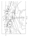
FIG. 2 is that of an aircraft flying a route of flight. Thedisplay 102 presents animage 200 preferably of a perspective view. Theimage 200 includes theterrain 202, one ormore markers 204, a desiredflight path 206 displayed on theterrain 202, one ormore waypoints 208, and theaircraft 210. The displayedmarkers 204 include, in addition to theweather 212 andspecial purpose areas 214, may includeterrain 202 and traffic (not shown). It is noted amarker 204 indicatingweather 212 when for turbulence, may include an altitude or a range of altitudes, for example, FL220 to FL280 wherein the turbulence is of concern. - A
vertical line 216, or pole, is associated with one or more of theweather icons 212,special purpose areas 214, andterrain 202. Acurrent altitude icon 218 may be positioned contiguous to one or more of thevertical lines 216 showing the current altitude of theaircraft 210. Additionally, atrending altitude icon 220 may be positioned contiguous to eachvertical line 216 that indicates an increasing or decreasing altitude based on thecurrent aircraft 210 energy state. As used herein, contiguous means touching or near. - A
vertical line 216 may also be associated with a waypoint. For example, thevertical line 222 is associated with the waypoint RILEY, wherein the current altitude is indicated by thewaypoint icon 224. - The format of the
vertical lines 216 and optionally the markers may be modified, e.g., highlighted, if within a threshold of the desiredflight path 206. For example, aswath 228 may be determined bases on a required navigation performance (RNP) or an estimate of position uncertainty (EPU). If the marker is within theswath 228, the format would be modified. RNP is a statement of the 95 percent navigation accuracy performance that meets a specified value for a particular phase of flight or flight segment and incorporates associated onboard performance-monitoring features, and designates the lateral performance requirement in NM increments. EPU is a defined statistical indication based on a defined scale in nautical miles, which conveys the current position estimation performance. - Highlighted means a visually distinguishable presentation, for example, by contrasting from other icons by using a different font, color, and intensity. The determining factor on when the indication is highlighted may be based on a location, including a distance to or from hazard, or it may be based on a time referenced to a hazard. While the hazard may be a location, it may also include temporal events related to the phases of flight.
- While the FMS preferably provides the information upon which the marker is defined, such information may be provided by databases for which the FMS does not have access.
-
FIG. 3 is a flow chart that illustrates an exemplary embodiment of amethod 300 suitable for use with a flightdeck display system 100.Method 300 represents one implementation of a method for displaying aircraft approaches or departures on an onboard display of a host aircraft. The various tasks performed in connection withmethod 300 may be performed by software, hardware, firmware, or any combination thereof. For illustrative purposes, the following description ofmethod 300 may refer to elements mentioned above in connection with preceding FIGS. In practice, portions ofmethod 300 may be performed by different elements of the described system, e.g., a processor, a display element, or a data communication component. It should be appreciated thatmethod 300 may include any number of additional or alternative tasks, the tasks shown inFIG. 3 need not be performed in the illustrated order, andmethod 300 may be incorporated into a more comprehensive procedure or method having additional functionality not described in detail herein. Moreover, one or more of the tasks shown inFIG. 3 could be omitted from an embodiment of themethod 300 as long as the intended overall functionality remains intact. - In accordance with the exemplary method of
FIG. 3 , a method of displaying a strategic navigational overview for a vehicle, comprises displaying 302 displaying a navigational map including a marker icon representing an entity pertinent to navigation of the vehicle; displaying 304 a vertical line contacting the marker icon; displaying 306 a current altitude icon contiguous to the vertical line representing a current altitude of the vehicle; and displaying 308 a trending icon contiguous to the vertical line indicating a direction of a change in altitude of the vehicle when the change exists. - Benefits, other advantages, and solutions to problems have been described above with regard to specific embodiments. However, the benefits, advantages, solutions to problems, and any element(s) that may cause any benefit, advantage, or solution to occur or become more pronounced are not to be construed as a critical, required, or essential feature or element of any or all the claims. As used herein, the terms "comprises," "comprising," or any other variation thereof, are intended to cover a non-exclusive inclusion, such that a process, method, article, or apparatus that comprises a list of elements does not include only those elements but may include other elements not expressly listed or inherent to such process, method, article, or apparatus.
- While at least one exemplary embodiment has been presented in the foregoing detailed description, it should be appreciated that a vast number of variations exist. It should also be appreciated that the exemplary embodiment or exemplary embodiments are only examples, and are not intended to limit the scope, applicability, or configuration of the invention in any way. Rather, the foregoing detailed description will provide those skilled in the art with a convenient road map for implementing an exemplary embodiment of the invention, it being understood that various changes may be made in the function and arrangement of elements described in an exemplary embodiment without departing from the scope of the invention as set forth in the appended claims.
Claims (15)
- A method of displaying a strategic navigational overview for a vehicle, comprising:displaying a navigational map including a marker icon representing an entity pertinent to navigation of the vehicle;displaying a vertical line contacting the marker icon;displaying a current altitude icon contiguous to the vertical line representing a current altitude of the vehicle; anddisplaying a trending icon contiguous to the vertical line indicating a direction of a change in altitude of the vehicle when the change exists.
- The method of claim 1, wherein the vertical line includes a first end contiguous to a terrain and a second end having the trending icon positioned thereon.
- The method of claim 1, wherein the marker icon represents weather pertinent to a route of flight of the vehicle.
- The method of claim 1, wherein the entity comprises the terrain pertinent to a route of flight of the vehicle.
- The method of claim 1, wherein the marker icon represents a special use area pertinent to a route of flight of the vehicle.
- The method of claim 1, wherein the marker icon represents a waypoint pertinent to a route of flight of the vehicle.
- The method of claim 1, wherein the processor is further configured to:determine if the marker is within a threshold associated with the desired route of flight; andmodify the format of the marker if the vehicle is within the threshold.
- The method of claim 1, wherein the processor is further configured to prompt the display to:display a swath encompassing the desired route of flight.
- The method of claim 8 wherein the dimensions of the swath are determined based on one of a required navigation performance or an estimate of position uncertainty.
- The method of claim 1 wherein the marker icon represents weather pertinent to a route of flight of the vehicle, the processor being further configured to prompt the display to:display an altitude or a range of altitudes associated with the weather.
- A system for displaying a strategic navigational overview for a vehicle, comprising:a display configured to:display a perspective navigational map;a processor coupled to the display and configured to prompt the display to:display a marker icon representing an entity pertinent to navigation of the vehicle;display a vertical line contacting the marker icon;display a current altitude icon contiguous to the vertical line representing a current altitude of the aircraft; anddisplay a trending icon contiguous to the vertical line indicating a direction of a change in altitude when the change exists.
- The system of claim 11, wherein the display is configured to display the vertical line having a first end contiguous to a terrain and a second end having the trending icon positioned thereon.
- The system of claim 11, wherein the marker represents one of the items pertinent to a route of flight selected from the group consisting of weather, terrain, a special use area, and a waypoint.
- The system of claim 11 wherein the processor is further configured to:determine if the vehicle is within a threshold associated with the desired route of flight; andmodify the format of the marker if the vehicle is not within the threshold.
- The system of claim 11, wherein the processor is further configured to prompt the display to:display a swath encompassing the desired route of flight, wherein the dimensions of the swath are determined based on one of a required navigation performance or an estimate of position uncertainty.
Applications Claiming Priority (1)
| Application Number | Priority Date | Filing Date | Title |
|---|---|---|---|
| US14/546,881 US9875659B2 (en) | 2014-11-18 | 2014-11-18 | System and method for exocentric display of integrated navigation |
Publications (2)
| Publication Number | Publication Date |
|---|---|
| EP3023741A1 true EP3023741A1 (en) | 2016-05-25 |
| EP3023741B1 EP3023741B1 (en) | 2018-08-15 |
Family
ID=54539987
Family Applications (1)
| Application Number | Title | Priority Date | Filing Date |
|---|---|---|---|
| EP15194153.1A Active EP3023741B1 (en) | 2014-11-18 | 2015-11-11 | System and method for exocentric display of integrated navigation |
Country Status (3)
| Country | Link |
|---|---|
| US (1) | US9875659B2 (en) |
| EP (1) | EP3023741B1 (en) |
| CN (1) | CN105651305B (en) |
Families Citing this family (6)
| Publication number | Priority date | Publication date | Assignee | Title |
|---|---|---|---|---|
| US20100131126A1 (en) * | 2008-11-21 | 2010-05-27 | Honeywell International Inc. | System and display element for displaying waypoint markers with integrated altitude constraint information |
| WO2016149039A1 (en) * | 2015-03-17 | 2016-09-22 | Sikorsky Aircraft Corporation | Trajectory control of a vehicle |
| US10446041B1 (en) * | 2018-08-23 | 2019-10-15 | Kitty Hawk Corporation | User interfaces for mutually exclusive three dimensional flying spaces |
| US10438495B1 (en) | 2018-08-23 | 2019-10-08 | Kitty Hawk Corporation | Mutually exclusive three dimensional flying spaces |
| FR3110728B1 (en) * | 2020-05-19 | 2022-04-29 | Thales Sa | Electronic device for displaying exocentric symbols, display method and related computer program product |
| US11789441B2 (en) | 2021-09-15 | 2023-10-17 | Beta Air, Llc | System and method for defining boundaries of a simulation of an electric aircraft |
Citations (7)
| Publication number | Priority date | Publication date | Assignee | Title |
|---|---|---|---|---|
| US4940987A (en) * | 1989-01-30 | 1990-07-10 | Frederick Philip R | Automatic horizontal and vertical scanning radar |
| US6057786A (en) * | 1997-10-15 | 2000-05-02 | Dassault Aviation | Apparatus and method for aircraft display and control including head up display |
| WO2001020583A2 (en) * | 1999-07-30 | 2001-03-22 | The Boeing Company | Flight information display |
| US20030156046A1 (en) * | 2002-02-20 | 2003-08-21 | Dwyer David B. | Apparatus for the display of weather and terrain information on a single display |
| EP2151669A2 (en) * | 2008-07-28 | 2010-02-10 | Honeywell International Inc. | System and method for displaying constraint information on a graphical aircraft instrument tape element |
| EP2189755A1 (en) * | 2008-11-21 | 2010-05-26 | Honeywell International Inc. | System and display element for displaying waypoint markers with integrated altitude constraint information |
| EP2199746A2 (en) * | 2008-12-17 | 2010-06-23 | Honeywell International Inc. | System and method for rendering aircraft traffic on a vertical situation display |
Family Cites Families (16)
| Publication number | Priority date | Publication date | Assignee | Title |
|---|---|---|---|---|
| US20030210228A1 (en) | 2000-02-25 | 2003-11-13 | Ebersole John Franklin | Augmented reality situational awareness system and method |
| FR2874371B1 (en) * | 2004-08-19 | 2007-12-21 | Airbus France Sas | DISPLAY SYSTEM FOR AN AIRCRAFT |
| US7375678B2 (en) | 2005-06-29 | 2008-05-20 | Honeywell International, Inc. | Displaying obstacles in perspective view |
| US7286062B2 (en) | 2005-06-29 | 2007-10-23 | Honeywell International, Inc. | Perspective view conformal traffic targets display |
| US8164485B2 (en) | 2006-04-13 | 2012-04-24 | The United States Of America As Represented By The Administrator Of The National Aeronautics And Space Administration | System and method for aiding pilot preview, rehearsal, review, and real-time visual acquisition of flight mission progress |
| FR2909213B1 (en) | 2006-11-28 | 2009-04-17 | Thales Sa | VISUALIZATION DEVICE FOR UNDERSTANDING THE AIR ENVIRONMENT. |
| US7917289B2 (en) | 2007-10-30 | 2011-03-29 | Honeywell International Inc. | Perspective view primary flight display system and method with range lines |
| US8099234B1 (en) | 2008-07-03 | 2012-01-17 | Rockwell Collins, Inc. | System, apparatus, and method for generating location information on an aircraft display unit using location markers |
| US8384730B1 (en) | 2008-09-26 | 2013-02-26 | Rockwell Collins, Inc. | System, module, and method for generating HUD image data from synthetic vision system image data |
| US8350753B2 (en) | 2009-02-16 | 2013-01-08 | Honeywell International Inc. | Methods and systems for displaying an object having an associated beacon signal |
| US8140260B2 (en) | 2010-02-12 | 2012-03-20 | Honeywell International Inc. | System for enhancing a vehicle operator's orientation and ability to navigate |
| US8456328B2 (en) | 2010-02-17 | 2013-06-04 | Honeywell International Inc. | System and method for informing an aircraft operator about a temporary flight restriction in perspective view |
| US8736465B2 (en) | 2011-01-17 | 2014-05-27 | L-3 Communications Avionics Systems, Inc. | Aircraft traffic display |
| US20120194556A1 (en) | 2011-01-28 | 2012-08-02 | L3 Communications Avionics Systems, Inc. | 3d avionics viewpoint control system |
| US20140331161A1 (en) * | 2013-05-03 | 2014-11-06 | Honeywell International Inc. | System and method for graphically displaying weather hazards in a perspective view |
| CN104077928B (en) * | 2014-07-03 | 2016-03-30 | 中国民航大学 | Be applicable to the navigation of irregular flight outside air route dot position information update method |
-
2014
- 2014-11-18 US US14/546,881 patent/US9875659B2/en active Active
-
2015
- 2015-11-11 EP EP15194153.1A patent/EP3023741B1/en active Active
- 2015-11-17 CN CN201511005710.4A patent/CN105651305B/en active Active
Patent Citations (7)
| Publication number | Priority date | Publication date | Assignee | Title |
|---|---|---|---|---|
| US4940987A (en) * | 1989-01-30 | 1990-07-10 | Frederick Philip R | Automatic horizontal and vertical scanning radar |
| US6057786A (en) * | 1997-10-15 | 2000-05-02 | Dassault Aviation | Apparatus and method for aircraft display and control including head up display |
| WO2001020583A2 (en) * | 1999-07-30 | 2001-03-22 | The Boeing Company | Flight information display |
| US20030156046A1 (en) * | 2002-02-20 | 2003-08-21 | Dwyer David B. | Apparatus for the display of weather and terrain information on a single display |
| EP2151669A2 (en) * | 2008-07-28 | 2010-02-10 | Honeywell International Inc. | System and method for displaying constraint information on a graphical aircraft instrument tape element |
| EP2189755A1 (en) * | 2008-11-21 | 2010-05-26 | Honeywell International Inc. | System and display element for displaying waypoint markers with integrated altitude constraint information |
| EP2199746A2 (en) * | 2008-12-17 | 2010-06-23 | Honeywell International Inc. | System and method for rendering aircraft traffic on a vertical situation display |
Also Published As
| Publication number | Publication date |
|---|---|
| CN105651305B (en) | 2021-03-23 |
| CN105651305A (en) | 2016-06-08 |
| US9875659B2 (en) | 2018-01-23 |
| US20160140850A1 (en) | 2016-05-19 |
| EP3023741B1 (en) | 2018-08-15 |
Similar Documents
| Publication | Publication Date | Title |
|---|---|---|
| EP2884478B1 (en) | System and method for textually and graphically presenting air traffic control voice information | |
| EP2851889B1 (en) | System and method for processing and displaying wake turbulence | |
| CN105549938B (en) | System and method for displaying runway landing information | |
| EP2400273B1 (en) | Methods and systems for displaying annotations on an aircraft display | |
| US9499279B2 (en) | System and method for displaying runway approach information | |
| EP2779140B1 (en) | System and method alerting an aircrew of threshold altitudes | |
| US9354078B2 (en) | Methods and systems for indicating whether an aircraft is within distance and altitude criteria for an IFR procedure turn | |
| EP3023741B1 (en) | System and method for exocentric display of integrated navigation | |
| EP2775469B1 (en) | System and method for managing an interval between aircraft | |
| US10214300B2 (en) | System and method for displaying runway overrun information | |
| EP2623935A1 (en) | System and method for displaying performance based range and time scales on a navigation display | |
| EP2980772B1 (en) | System and method for automatically identifying displayed atc mentioned traffic | |
| US8810435B2 (en) | Apparatus and method for displaying a helicopter approach to an airport landing pad | |
| EP2940674A1 (en) | System and method for displaying context sensitive notes | |
| EP2762837A2 (en) | System and method for displaying terrain altitudes on an aircraft display | |
| EP3657131B1 (en) | Waypoint list presentation methods and systems | |
| EP2866112B1 (en) | System and method for modulating alerts for an intended runway | |
| US9448702B2 (en) | Methods and systems for selecting a displayed aircraft approach or departure |
Legal Events
| Date | Code | Title | Description |
|---|---|---|---|
| 17P | Request for examination filed |
Effective date: 20151111 |
|
| AK | Designated contracting states |
Kind code of ref document: A1 Designated state(s): AL AT BE BG CH CY CZ DE DK EE ES FI FR GB GR HR HU IE IS IT LI LT LU LV MC MK MT NL NO PL PT RO RS SE SI SK SM TR |
|
| AX | Request for extension of the european patent |
Extension state: BA ME |
|
| PUAI | Public reference made under article 153(3) epc to a published international application that has entered the european phase |
Free format text: ORIGINAL CODE: 0009012 |
|
| GRAP | Despatch of communication of intention to grant a patent |
Free format text: ORIGINAL CODE: EPIDOSNIGR1 |
|
| 17Q | First examination report despatched |
Effective date: 20180220 |
|
| INTG | Intention to grant announced |
Effective date: 20180328 |
|
| GRAS | Grant fee paid |
Free format text: ORIGINAL CODE: EPIDOSNIGR3 |
|
| GRAA | (expected) grant |
Free format text: ORIGINAL CODE: 0009210 |
|
| AK | Designated contracting states |
Kind code of ref document: B1 Designated state(s): AL AT BE BG CH CY CZ DE DK EE ES FI FR GB GR HR HU IE IS IT LI LT LU LV MC MK MT NL NO PL PT RO RS SE SI SK SM TR |
|
| REG | Reference to a national code |
Ref country code: CH Ref legal event code: EP Ref country code: GB Ref legal event code: FG4D Ref country code: AT Ref legal event code: REF Ref document number: 1030312 Country of ref document: AT Kind code of ref document: T Effective date: 20180815 |
|
| REG | Reference to a national code |
Ref country code: IE Ref legal event code: FG4D |
|
| REG | Reference to a national code |
Ref country code: DE Ref legal event code: R096 Ref document number: 602015014714 Country of ref document: DE |
|
| REG | Reference to a national code |
Ref country code: NL Ref legal event code: MP Effective date: 20180815 |
|
| REG | Reference to a national code |
Ref country code: LT Ref legal event code: MG4D |
|
| REG | Reference to a national code |
Ref country code: AT Ref legal event code: MK05 Ref document number: 1030312 Country of ref document: AT Kind code of ref document: T Effective date: 20180815 |
|
| PG25 | Lapsed in a contracting state [announced via postgrant information from national office to epo] |
Ref country code: FI Free format text: LAPSE BECAUSE OF FAILURE TO SUBMIT A TRANSLATION OF THE DESCRIPTION OR TO PAY THE FEE WITHIN THE PRESCRIBED TIME-LIMIT Effective date: 20180815 Ref country code: IS Free format text: LAPSE BECAUSE OF FAILURE TO SUBMIT A TRANSLATION OF THE DESCRIPTION OR TO PAY THE FEE WITHIN THE PRESCRIBED TIME-LIMIT Effective date: 20181215 Ref country code: AT Free format text: LAPSE BECAUSE OF FAILURE TO SUBMIT A TRANSLATION OF THE DESCRIPTION OR TO PAY THE FEE WITHIN THE PRESCRIBED TIME-LIMIT Effective date: 20180815 Ref country code: GR Free format text: LAPSE BECAUSE OF FAILURE TO SUBMIT A TRANSLATION OF THE DESCRIPTION OR TO PAY THE FEE WITHIN THE PRESCRIBED TIME-LIMIT Effective date: 20181116 Ref country code: NO Free format text: LAPSE BECAUSE OF FAILURE TO SUBMIT A TRANSLATION OF THE DESCRIPTION OR TO PAY THE FEE WITHIN THE PRESCRIBED TIME-LIMIT Effective date: 20181115 Ref country code: RS Free format text: LAPSE BECAUSE OF FAILURE TO SUBMIT A TRANSLATION OF THE DESCRIPTION OR TO PAY THE FEE WITHIN THE PRESCRIBED TIME-LIMIT Effective date: 20180815 Ref country code: BG Free format text: LAPSE BECAUSE OF FAILURE TO SUBMIT A TRANSLATION OF THE DESCRIPTION OR TO PAY THE FEE WITHIN THE PRESCRIBED TIME-LIMIT Effective date: 20181115 Ref country code: SE Free format text: LAPSE BECAUSE OF FAILURE TO SUBMIT A TRANSLATION OF THE DESCRIPTION OR TO PAY THE FEE WITHIN THE PRESCRIBED TIME-LIMIT Effective date: 20180815 Ref country code: NL Free format text: LAPSE BECAUSE OF FAILURE TO SUBMIT A TRANSLATION OF THE DESCRIPTION OR TO PAY THE FEE WITHIN THE PRESCRIBED TIME-LIMIT Effective date: 20180815 Ref country code: LT Free format text: LAPSE BECAUSE OF FAILURE TO SUBMIT A TRANSLATION OF THE DESCRIPTION OR TO PAY THE FEE WITHIN THE PRESCRIBED TIME-LIMIT Effective date: 20180815 |
|
| PG25 | Lapsed in a contracting state [announced via postgrant information from national office to epo] |
Ref country code: HR Free format text: LAPSE BECAUSE OF FAILURE TO SUBMIT A TRANSLATION OF THE DESCRIPTION OR TO PAY THE FEE WITHIN THE PRESCRIBED TIME-LIMIT Effective date: 20180815 Ref country code: LV Free format text: LAPSE BECAUSE OF FAILURE TO SUBMIT A TRANSLATION OF THE DESCRIPTION OR TO PAY THE FEE WITHIN THE PRESCRIBED TIME-LIMIT Effective date: 20180815 Ref country code: AL Free format text: LAPSE BECAUSE OF FAILURE TO SUBMIT A TRANSLATION OF THE DESCRIPTION OR TO PAY THE FEE WITHIN THE PRESCRIBED TIME-LIMIT Effective date: 20180815 |
|
| PG25 | Lapsed in a contracting state [announced via postgrant information from national office to epo] |
Ref country code: CZ Free format text: LAPSE BECAUSE OF FAILURE TO SUBMIT A TRANSLATION OF THE DESCRIPTION OR TO PAY THE FEE WITHIN THE PRESCRIBED TIME-LIMIT Effective date: 20180815 Ref country code: RO Free format text: LAPSE BECAUSE OF FAILURE TO SUBMIT A TRANSLATION OF THE DESCRIPTION OR TO PAY THE FEE WITHIN THE PRESCRIBED TIME-LIMIT Effective date: 20180815 Ref country code: ES Free format text: LAPSE BECAUSE OF FAILURE TO SUBMIT A TRANSLATION OF THE DESCRIPTION OR TO PAY THE FEE WITHIN THE PRESCRIBED TIME-LIMIT Effective date: 20180815 Ref country code: PL Free format text: LAPSE BECAUSE OF FAILURE TO SUBMIT A TRANSLATION OF THE DESCRIPTION OR TO PAY THE FEE WITHIN THE PRESCRIBED TIME-LIMIT Effective date: 20180815 Ref country code: EE Free format text: LAPSE BECAUSE OF FAILURE TO SUBMIT A TRANSLATION OF THE DESCRIPTION OR TO PAY THE FEE WITHIN THE PRESCRIBED TIME-LIMIT Effective date: 20180815 Ref country code: IT Free format text: LAPSE BECAUSE OF FAILURE TO SUBMIT A TRANSLATION OF THE DESCRIPTION OR TO PAY THE FEE WITHIN THE PRESCRIBED TIME-LIMIT Effective date: 20180815 |
|
| PGFP | Annual fee paid to national office [announced via postgrant information from national office to epo] |
Ref country code: DE Payment date: 20190131 Year of fee payment: 4 |
|
| REG | Reference to a national code |
Ref country code: DE Ref legal event code: R097 Ref document number: 602015014714 Country of ref document: DE |
|
| PG25 | Lapsed in a contracting state [announced via postgrant information from national office to epo] |
Ref country code: DK Free format text: LAPSE BECAUSE OF FAILURE TO SUBMIT A TRANSLATION OF THE DESCRIPTION OR TO PAY THE FEE WITHIN THE PRESCRIBED TIME-LIMIT Effective date: 20180815 Ref country code: SM Free format text: LAPSE BECAUSE OF FAILURE TO SUBMIT A TRANSLATION OF THE DESCRIPTION OR TO PAY THE FEE WITHIN THE PRESCRIBED TIME-LIMIT Effective date: 20180815 Ref country code: SK Free format text: LAPSE BECAUSE OF FAILURE TO SUBMIT A TRANSLATION OF THE DESCRIPTION OR TO PAY THE FEE WITHIN THE PRESCRIBED TIME-LIMIT Effective date: 20180815 |
|
| PLBE | No opposition filed within time limit |
Free format text: ORIGINAL CODE: 0009261 |
|
| STAA | Information on the status of an ep patent application or granted ep patent |
Free format text: STATUS: NO OPPOSITION FILED WITHIN TIME LIMIT |
|
| REG | Reference to a national code |
Ref country code: CH Ref legal event code: PL |
|
| 26N | No opposition filed |
Effective date: 20190516 |
|
| PG25 | Lapsed in a contracting state [announced via postgrant information from national office to epo] |
Ref country code: MC Free format text: LAPSE BECAUSE OF FAILURE TO SUBMIT A TRANSLATION OF THE DESCRIPTION OR TO PAY THE FEE WITHIN THE PRESCRIBED TIME-LIMIT Effective date: 20180815 Ref country code: LU Free format text: LAPSE BECAUSE OF NON-PAYMENT OF DUE FEES Effective date: 20181111 |
|
| REG | Reference to a national code |
Ref country code: BE Ref legal event code: MM Effective date: 20181130 |
|
| REG | Reference to a national code |
Ref country code: IE Ref legal event code: MM4A |
|
| PG25 | Lapsed in a contracting state [announced via postgrant information from national office to epo] |
Ref country code: LI Free format text: LAPSE BECAUSE OF NON-PAYMENT OF DUE FEES Effective date: 20181130 Ref country code: CH Free format text: LAPSE BECAUSE OF NON-PAYMENT OF DUE FEES Effective date: 20181130 Ref country code: SI Free format text: LAPSE BECAUSE OF FAILURE TO SUBMIT A TRANSLATION OF THE DESCRIPTION OR TO PAY THE FEE WITHIN THE PRESCRIBED TIME-LIMIT Effective date: 20180815 |
|
| PG25 | Lapsed in a contracting state [announced via postgrant information from national office to epo] |
Ref country code: IE Free format text: LAPSE BECAUSE OF NON-PAYMENT OF DUE FEES Effective date: 20181111 |
|
| PG25 | Lapsed in a contracting state [announced via postgrant information from national office to epo] |
Ref country code: BE Free format text: LAPSE BECAUSE OF NON-PAYMENT OF DUE FEES Effective date: 20181130 |
|
| PG25 | Lapsed in a contracting state [announced via postgrant information from national office to epo] |
Ref country code: MT Free format text: LAPSE BECAUSE OF NON-PAYMENT OF DUE FEES Effective date: 20181111 |
|
| PG25 | Lapsed in a contracting state [announced via postgrant information from national office to epo] |
Ref country code: TR Free format text: LAPSE BECAUSE OF FAILURE TO SUBMIT A TRANSLATION OF THE DESCRIPTION OR TO PAY THE FEE WITHIN THE PRESCRIBED TIME-LIMIT Effective date: 20180815 |
|
| PG25 | Lapsed in a contracting state [announced via postgrant information from national office to epo] |
Ref country code: PT Free format text: LAPSE BECAUSE OF FAILURE TO SUBMIT A TRANSLATION OF THE DESCRIPTION OR TO PAY THE FEE WITHIN THE PRESCRIBED TIME-LIMIT Effective date: 20180815 |
|
| REG | Reference to a national code |
Ref country code: DE Ref legal event code: R119 Ref document number: 602015014714 Country of ref document: DE |
|
| PG25 | Lapsed in a contracting state [announced via postgrant information from national office to epo] |
Ref country code: MK Free format text: LAPSE BECAUSE OF NON-PAYMENT OF DUE FEES Effective date: 20180815 Ref country code: HU Free format text: LAPSE BECAUSE OF FAILURE TO SUBMIT A TRANSLATION OF THE DESCRIPTION OR TO PAY THE FEE WITHIN THE PRESCRIBED TIME-LIMIT; INVALID AB INITIO Effective date: 20151111 Ref country code: CY Free format text: LAPSE BECAUSE OF FAILURE TO SUBMIT A TRANSLATION OF THE DESCRIPTION OR TO PAY THE FEE WITHIN THE PRESCRIBED TIME-LIMIT Effective date: 20180815 |
|
| PG25 | Lapsed in a contracting state [announced via postgrant information from national office to epo] |
Ref country code: DE Free format text: LAPSE BECAUSE OF NON-PAYMENT OF DUE FEES Effective date: 20200603 |
|
| P01 | Opt-out of the competence of the unified patent court (upc) registered |
Effective date: 20230525 |
|
| PGFP | Annual fee paid to national office [announced via postgrant information from national office to epo] |
Ref country code: GB Payment date: 20231121 Year of fee payment: 9 |
|
| PGFP | Annual fee paid to national office [announced via postgrant information from national office to epo] |
Ref country code: FR Payment date: 20231123 Year of fee payment: 9 |