EP2623935A1 - System and method for displaying performance based range and time scales on a navigation display - Google Patents
System and method for displaying performance based range and time scales on a navigation display Download PDFInfo
- Publication number
- EP2623935A1 EP2623935A1 EP13152232.8A EP13152232A EP2623935A1 EP 2623935 A1 EP2623935 A1 EP 2623935A1 EP 13152232 A EP13152232 A EP 13152232A EP 2623935 A1 EP2623935 A1 EP 2623935A1
- Authority
- EP
- European Patent Office
- Prior art keywords
- range
- time
- display
- symbology
- displaying
- Prior art date
- Legal status (The legal status is an assumption and is not a legal conclusion. Google has not performed a legal analysis and makes no representation as to the accuracy of the status listed.)
- Granted
Links
Images


Classifications
-
- G—PHYSICS
- G01—MEASURING; TESTING
- G01C—MEASURING DISTANCES, LEVELS OR BEARINGS; SURVEYING; NAVIGATION; GYROSCOPIC INSTRUMENTS; PHOTOGRAMMETRY OR VIDEOGRAMMETRY
- G01C23/00—Combined instruments indicating more than one navigational value, e.g. for aircraft; Combined measuring devices for measuring two or more variables of movement, e.g. distance, speed or acceleration
- G01C23/005—Flight directors
-
- G—PHYSICS
- G08—SIGNALLING
- G08G—TRAFFIC CONTROL SYSTEMS
- G08G5/00—Traffic control systems for aircraft, e.g. air-traffic control [ATC]
- G08G5/0017—Arrangements for implementing traffic-related aircraft activities, e.g. arrangements for generating, displaying, acquiring or managing traffic information
- G08G5/0021—Arrangements for implementing traffic-related aircraft activities, e.g. arrangements for generating, displaying, acquiring or managing traffic information located in the aircraft
Definitions
- Embodiments of the subject matter described herein relate generally to vehicular display systems and, more particularly, to an avionics display system for visually expressing flight information on a host aircraft that includes performance based time and range scales.
- Avionics display systems deployed aboard aircraft have been extensively engineered to visually convey a considerable amount of flight information in an intuitive and readily comprehendible manner.
- a display such as a primary flight display
- the majority of the information visually expressed on a display pertains to the host aircraft's flight parameters (e.g., the heading, drift, roll, and pitch of the host aircraft), nearby geographical features (e.g., mountain peaks, runways, etc.), and current weather conditions (e.g., developing storm cells).
- flight parameters e.g., the heading, drift, roll, and pitch of the host aircraft
- nearby geographical features e.g., mountain peaks, runways, etc.
- current weather conditions e.g., developing storm cells
- next Generation Air Transportation System or, more simply, “NextGen”
- NextGen Next Generation Air Transportation System
- a multi-function display is a device typically mounted on the instrument panel of an aircraft for displaying information and data associated with radar, weapons stores, navigation, etc.
- the MFD is divided into sections, which can be selected and viewed by a crew member.
- a navigational map display is one of the most important pages available on the MFD and visually represents what one would see looking directly down on the aircraft or other point of interest; e.g. waypoints, destination city, etc.
- the following discussion will focus on the scenario which places the host aircraft at the center of at least one range ring displayed of the lateral map or navigational map and representing a specified distance from the host aircraft.
- three concentric range rings around a host aircraft may each represent one third of the currently selected display range; i.e. if the display range is fifteen nautical miles (NM), each ring may represent an increment of five NM.
- NextGen operations will require more precise trajectory management in both the space and time domains (i.e. 4D navigation).
- flight crews must not only understand and visualize both current and intended trajectories, but must also understand the time scales associated with partial or entire trajectories. This is essential in NextGen operations involving both spatial and time constraints for maximum system efficiency and throughput.
- Typical navigation displays provide only spatial scale display with limited time information augmentation; e.g. time windows and time maps. As such, these solutions offer only limited situational awareness in the time domain. Thus, it should be clear that to meet 4-D navigation requirements and increase a pilot's situational awareness within the time domain, it would be desirable to provide performance based range and time scales synchronized in the sense that as one is adjusted, the other is automatically and similarly updated.
- a display system for deployment on board a vehicle and includes a data source that provides the display system with data indicative of at least time, position, and velocity of the vehicle.
- the system comprises a monitor, a display included within the monitor for displaying range data indicative of a specific distance and time data indicative of time it takes to travel the specific distance, an input device, and a processor coupled to the monitor and to the input device and configured to (1) render symbology on the display visually representative of the time data and the range data, and (2) update the range data, and correspondingly change the time data in response to the change in range data made via the input device.
- a method for displaying a range window and a time window on a display in a vehicular display system and visually rendering on the display a textual representation of the distance between a first location to a second location and the travel-time from the first location to the second location.
- the method comprises generating range symbology visually representative of the distance, displaying the range symbology on the display, generating symbology visually representative of the travel time, displaying the travel-time symbology on the display, changing the displayed travel time via an input device, generating updated range symbology corresponding to the change in travel-time, and displaying the updated range symbology.
- an avionics display system including a cockpit display, a monitor, a processor, and input device coupled to the processor, deployed on a host aircraft, for visually rendering on the cockpit display the distance between a first location and a second location and the flight-time from the first location to the second location.
- the process comprises generating range symbology in the processor visually representative of the distance between the first location and the second location, displaying the range symbology on the vehicle display, generating time symbology in the processor visually representative of the time to fly from the first location to the second location, displaying the time symbology on the cockpit display, changing the time symbology via the input device, and updating the range symbology in response to changing the time symbology.
- FIG. 1 is functional block diagram of a generalized avionics display system in accordance with an exemplary embodiment
- FIG. 2 is a typical horizontal situation display illustrating an aircraft surrounded by first and second range rings
- FIG. 3 is shown an HSD display in accordance with a first embodiment and having a host aircraft centered thereon;
- FIG. 4 illustrates an HSD in accordance with a second embodiment and having a waypoint centered thereon
- FIG. 5 illustrates an HSD in accordance with a third embodiment and having an aircraft centered thereon followed by a host aircraft
- FIG. 6 is a flowchart illustrating an exemplary embodiment of a method for displaying performance based range and time scales on a navigation display.
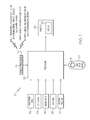
- FIG. 1 is a functional block diagram of a generalized avionics display system 20 in accordance with an exemplary embodiment.
- Avionics display system 20 includes at least one processor 22 and at least one monitor 24, which is operatively coupled to processor 22.
- An input device 30 e.g. cursor control device, keyboard, touchscreen, rotary knob, etc.
- processor 22 drives monitor 24 to produce a graphical display 26 that visually provides a pilot and crew with navigational informational pertaining to the host aircraft and to neighboring aircraft within a predetermined vicinity of the host aircraft.
- Graphical display 26 may include visual representations of one or more of flight characteristics pertaining to a neighboring aircraft, as described more fully below.
- Processor 22 may generate display 26 in a two dimensional format (e.g., as a moving map display), in a three dimensional format (e.g., as a perspective display), or in a hybrid format (e.g., in a picture-in-picture or split screen arrangement).
- Processor 22 may comprise, or be associated with, any suitable number of individual microprocessors, flight control computers, navigational equipment, memories, power supplies, storage devices, interface cards, and other standard components known in the art.
- the processor 22 may include or cooperate with any number of software programs (e.g., avionics display programs) or instructions designed to carry out the various methods, process tasks, calculations, and control/display functions described below.
- processor 22 is included within a Flight Management Computer of the type commonly deployed within a Flight Management System (FMS).
- FMS Flight Management System
- the processor architecture 22 may include or cooperate with an appropriate amount of memory (not shown), which can be realized as RAM memory, flash memory, EPROM memory, EEPROM memory, registers, a hard disk, a removable disk, a CD-ROM, or any other form of storage medium known in the art.
- the memory can be coupled to the processor architecture 22 such that the processor architecture 22 can read information from, and write information to, the memory.
- the memory may be integral to the processor architecture 22.
- a functional or logical module/component of the system described here might be realized using program code that is maintained in the memory.
- the memory can be used to store data utilized to support the operation of the system.
- the display 26 cooperates with a suitably configured graphics system (not shown). This allows the display 26 to display, render, or otherwise convey one or more graphical representations, synthetic displays, graphical icons, visual symbology, or images associated with operation of the host aircraft on the display element, as described in greater detail below.
- the display element receives image rendering display commands from processor 22.
- the user input device 30 may be realized as a user input device that receives input from a user (e.g., a pilot) and, in response to the user input, supplies appropriate signals to processor 22.
- the user interface may be any one, or any combination, of various known user input devices or technologies, including, but not limited to: a cursor control device such as a mouse, trackball, joystick, keyboard, buttons, switches, or knobs.
- the user interface may cooperate with the display 26 to provide a touch screen interface.
- the user input device 30 may be utilized to vary range and/or time of closure as will be described in more detail below.
- monitor 24 may assume the form of a Head-Down Display (HDD) or a Head-Up Display (HUD) included within an aircraft's Electronic Flight Instrument System (EFIS).
- HDD Head-Down Display
- HUD Head-Up Display
- EFIS Electronic Flight Instrument System
- Monitor 24 may be disposed at various locations throughout the cockpit.
- monitor 24 may comprise a primary flight display (PFD) and reside at a central location within the pilot's primary field-of-view.
- monitor 24 may comprise a secondary flight deck display, such as an Engine Instrument and Crew Advisory System (EICAS) display, mounted at a location for convenient observation by the aircraft crew but that generally resides outside of the pilot's primary field-of-view.
- EICAS Engine Instrument and Crew Advisory System
- Processor 22 includes one or more inputs operatively coupled to one or more data sources.
- TCAS and/or radar continually provide processor 22 with data pertaining to neighboring aircraft.
- the data sources include a wireless transceiver 28 and a source of navigation data 32, which are operatively coupled to first and second inputs of processor 22, respectively.
- Navigation data source 32 may include an onboard radar and various other onboard instrumentation, such as a radio altimeter, a barometric altimeter, a global positioning system (GPS) unit, and the like.
- GPS global positioning system
- the FMS system receives and combines this data to produce the trajectory that the aircraft follows.
- An onboard radar altimeter may be included within a Terrain Awareness and Warning System (TAWS), such as an Enhanced Ground Proximity Warning System (EGPWS).
- TAWS Terrain Awareness and Warning System
- EGPWS Enhanced Ground Proximity Warning System
- wireless transceiver 28 receives navigational data from external control sources and relays this data to processor 22.
- wireless transceiver 28 may receive Traffic Information Services-Broadcast (TIS-B) data from external control sources, such as satellite and various ground-based facilities including Air Traffic Control Centers, Terminal Radar Approach Control Facilities, Flight Service Stations, control towers, and the like.
- TIS-B Traffic Information Services-Broadcast
- wireless transceiver 28 may receive Automatic Dependent Surveillance-Broadcast (ADS-B) data and Traffic Collision Avoidance System (TCAS) from neighboring aircraft.
- ADS-B Automatic Dependent Surveillance-Broadcast
- TCAS Traffic Collision Avoidance System
- TIS-B data, ADS-B data, and TCAS data other such external source data is preferably formatted to include air traffic state vector information, which may be utilized to determine a neighboring aircraft's current position.
- the TIS-B data, the ADS-B, and/or the TCAS data may also be formatted to include additional information useful in determining other flight characteristics of the neighboring aircraft including the neighboring aircraft's current flight plan.
- Databases 34 represent sources of data and information that relate to flight plan, , terrain, restricted airspace, waypoints, destination and departing airports, etc.
- Weather data such as wind profile and thunderstorm information can be provided to the aircraft via datalink 38.
- Air data system 40 supplies current flying parameters such as airspeed that the FMS and other on-board system used to compute and project current and future trajectories and performance parameters.
- the combined system provides data such as current estimated gross weight of the aircraft, aircraft GPS position, aircraft groundspeed, and environmental conditions such as outside air temperature, weather, RVR visibility wind speed and direction, and local or zulu time of day, etc. Some of this data may be entered into processor 22 manually by a crew-member.
- Sensor data sources 36 represents various sensor elements, detectors, diagnostic components, and their associated subsystems onboard the aircraft.
- the sensor data sources 36 function as sources of aircraft status data for the host aircraft, including, without limitation, data indicative of outside temperature, aircraft ground speed, geographic position of the aircraft, electric taxi, or the like.
- Data sources 28, 32, 34, 36, 38, and 40 described in connection with FIG. 1 provide static and/or real-time information to processor 22, which processor 22 may utilize to generate one or more displays on display 26, such as the horizontal situation display of a multi-function display.
- the data sources may include a wide variety of informational systems, which may reside onboard the aircraft or at a remote location.
- the data sources may include one or more of the following systems: an instrument landing system, an airport data base, a flight director system, a weather data system, a terrain avoidance and warning system, a traffic and collision avoidance system, a terrain database, an inertial reference system, and a navigational database.
- the data sources may also include mode, position, and/or detection elements (e.g., gyroscopes, global positioning systems, inertial reference systems, etc.) capable of determining the mode and/or position of the aircraft relative to one or more reference locations, points, planes, or navigation aids.
- Mode, position, and/or detection elements e.g., gyroscopes, global positioning systems, inertial reference systems, etc.
- Data may be retrieved from other sources (e.g. FMS, GPS, etc.) or manually entered if no guidance system is available.
- the data described above may be utilized by processor 22 to achieve more precise 4D flight management, utilizing an understanding of time scales associated with flight trajectories.
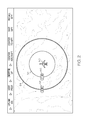
- FIG. 2 illustrates a typical navigational map display including host aircraft 50 and, for example, first and second range rings 52 and 54 graphically displayed concentrically around aircraft 50.
- symbology in the form of a first window 56 is graphically positioned on range ring 52.
- This window textually indicates and visually representing that aircraft 50 is, for example, 25 NM from any point on range ring 52.
- symbology in the form of a second window 58 is graphically displayed on range ring 54.
- Window 58 textually indicates and visually represents that aircraft 50 is, for example, 50 NM from any point on range ring 54.
- a greater or lesser number of range rings may be displayed.
- the HSD display shown in FIG. 2 yields information in the spatial domain (i.e. distance), it gives a crew-member little or no information in the time domain.
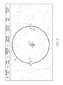
- range ring 62 is graphically displayed around host aircraft 60. Only a single range ring is shown for clarity; however, the following discussion is equally applicable to an HSD display including multiple range rings.
- symbology in the form of a first window 64 is graphically positioned on range ring 62 to textually indicate a range of, for example, 50 NM from aircraft 60.
- FIG. 2 unlike FIG.
- symbology in the form of a second window 66 is generated on range ring 62, and symbology is generated and displayed within window 66 visually representing the predicted elapsed flight-time necessary to reach the distance displayed on range ring 62 under current flight conditions; e.g. current ground speed, wind profile, predicted ground speed for the region displayed, etc.
- This predicted time is determined by processor 22 ( FIG. 1 ) based on the range (in window 64) and factoring in the relevant data supplied to processor 22 and described in connection with FIG. 1 .
- the predicted time may be based on current ground speed whereas when the map is entered on, for example, a waypoint well ahead of the current aircraft position and perhaps under a required-time-of-arrival (RTA) constraint, the predicted time may be determined using predicted ground speed at that location, where the prediction is typically based on full trajectory optimization to achieve the required time of arrival at the point. If the map is centered on a location not currently on the stored flight plan, the time scale may be determined using predicted ground-speed based on current heading directly to that location.
- RTA required-time-of-arrival
- the embodiments described herein contemplate the automatic updating of the time scale when the range scale is altered, and/or the automatic updating of the range scale when the time scale is altered.
- user input device 30 may be used to select either the range window or the time window and alter the contents thereof via, for example, a rotating knob 31. This results in the automatic updating of the contents of the non-selected window. That is, when processor 22 recognizes that the time or range window has been selected and the contents thereof have been changed, processor 22 will determine the value of the non-selected window and generate the required symbology for display in the non-selected window utilizing the data described in connection with FIG. 1 .
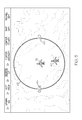
- FIG. 4 illustrates a scenario wherein the map is centered on other than the host aircraft; for example, a waypoint 20.
- This may be useful for determining range and time parameters resulting from flight characteristics (e.g. wind, weather, etc.) in the vicinity of waypoint 70. It may also be useful to utilize the time and range scales to meet NextGen Required-Time-of-Arrival (RTA) requirements. That is, by manipulating and monitoring the time and range scales, aircraft performance characteristics may be adjusted to meet the RTA.
- RTA NextGen Required-Time-of-Arrival
- FIG. 6 is a flowchart illustrating an exemplary embodiment of a method of displaying performance based range and time scales on a navigation display.
- the method begins when range symbology and time symbology are generated by processor 22 (STEP 80 and STEP 82, respectively) and subsequently provided to monitor 24 for display on display 26 (STEP 84 and STEP 86, respectively).
- The proceeds by detecting a change made to the range or to the time via the input device 30 (STEP 88 and STEP 90, respectively). If a change in range made via input device 30 is detected, the computer updates the time displayed accordingly (STEP 92).
- processor 22 will determine the corresponding increase or decrease, respectively, in time, symbology reflective of the change in time to be generated, and provide that symbology to monitor 24 for display on display 26 (STEP 92). That is, knowing the operational parameters of the vehicle (e.g. ground speed, etc.) it is a simple matter for processor to determine the time it will take to reach the new range. Similarly, if an increase or decrease in elapsed time made via input device 30 is detected, processor 22 will determine the corresponding increase or decrease, respectively, in range, cause symbology reflective of the change in range to be generated, and provide that symbology to monitor 24 for display.
- processor 22 will determine the corresponding increase or decrease, respectively, in time, cause symbology reflective of the change in range to be generated, and provide that symbology to monitor 24 for display.
Abstract
Description
- Embodiments of the subject matter described herein relate generally to vehicular display systems and, more particularly, to an avionics display system for visually expressing flight information on a host aircraft that includes performance based time and range scales.
- Avionics display systems deployed aboard aircraft have been extensively engineered to visually convey a considerable amount of flight information in an intuitive and readily comprehendible manner. In conventional avionics display systems, the majority of the information visually expressed on a display, such as a primary flight display, pertains to the host aircraft's flight parameters (e.g., the heading, drift, roll, and pitch of the host aircraft), nearby geographical features (e.g., mountain peaks, runways, etc.), and current weather conditions (e.g., developing storm cells). Aside from a neighboring aircraft's current detected position, conventional avionics display systems typically provide little, if any, visual information pertaining to neighboring aircraft. This may be due, in part, to current air traffic management ("ATM") practices wherein air traffic management is generally managed by personnel stationed within air traffic control and other ground-based control facilities. However, conventional control facility-based ATM systems are inherently limited in the volume of air traffic that they can effectively manage during a given time period. For this reason, the United States has commenced the development and implementation of a modernized ATM system (commonly referred to as the "Next Generation Air Transportation System" or, more simply, "NextGen") in which air traffic management will be largely handled by individual flight crews utilizing data compiled from a constellation of computerized systems onboard, satellites, and neighboring aircraft.
- A multi-function display (MFD) is a device typically mounted on the instrument panel of an aircraft for displaying information and data associated with radar, weapons stores, navigation, etc. The MFD is divided into sections, which can be selected and viewed by a crew member. A navigational map display is one of the most important pages available on the MFD and visually represents what one would see looking directly down on the aircraft or other point of interest; e.g. waypoints, destination city, etc. For the sake of convenience, the following discussion will focus on the scenario which places the host aircraft at the center of at least one range ring displayed of the lateral map or navigational map and representing a specified distance from the host aircraft. For example, three concentric range rings around a host aircraft may each represent one third of the currently selected display range; i.e. if the display range is fifteen nautical miles (NM), each ring may represent an increment of five NM.
- However, NextGen operations will require more precise trajectory management in both the space and time domains (i.e. 4D navigation). Thus, flight crews must not only understand and visualize both current and intended trajectories, but must also understand the time scales associated with partial or entire trajectories. This is essential in NextGen operations involving both spatial and time constraints for maximum system efficiency and throughput.
- Typical navigation displays provide only spatial scale display with limited time information augmentation; e.g. time windows and time maps. As such, these solutions offer only limited situational awareness in the time domain. Thus, it should be clear that to meet 4-D navigation requirements and increase a pilot's situational awareness within the time domain, it would be desirable to provide performance based range and time scales synchronized in the sense that as one is adjusted, the other is automatically and similarly updated.
- A display system is provided for deployment on board a vehicle and includes a data source that provides the display system with data indicative of at least time, position, and velocity of the vehicle. The system comprises a monitor, a display included within the monitor for displaying range data indicative of a specific distance and time data indicative of time it takes to travel the specific distance, an input device, and a processor coupled to the monitor and to the input device and configured to (1) render symbology on the display visually representative of the time data and the range data, and (2) update the range data, and correspondingly change the time data in response to the change in range data made via the input device.
- A method is also provided for displaying a range window and a time window on a display in a vehicular display system and visually rendering on the display a textual representation of the distance between a first location to a second location and the travel-time from the first location to the second location. The method comprises generating range symbology visually representative of the distance, displaying the range symbology on the display, generating symbology visually representative of the travel time, displaying the travel-time symbology on the display, changing the displayed travel time via an input device, generating updated range symbology corresponding to the change in travel-time, and displaying the updated range symbology.
- Additionally, there is provided a process to be carried out by an avionics display system including a cockpit display, a monitor, a processor, and input device coupled to the processor, deployed on a host aircraft, for visually rendering on the cockpit display the distance between a first location and a second location and the flight-time from the first location to the second location. the process comprises generating range symbology in the processor visually representative of the distance between the first location and the second location, displaying the range symbology on the vehicle display, generating time symbology in the processor visually representative of the time to fly from the first location to the second location, displaying the time symbology on the cockpit display, changing the time symbology via the input device, and updating the range symbology in response to changing the time symbology.
- Furthermore, other desirable features and characteristics of the [system/method] will become apparent from the subsequent detailed description and the appended claims, taken in conjunction with the accompanying drawings and the preceding background.
- At least one example of the present invention will hereinafter be described in conjunction with the following figures, wherein like numerals denote like elements, and:
-
FIG. 1 is functional block diagram of a generalized avionics display system in accordance with an exemplary embodiment; -
FIG. 2 is a typical horizontal situation display illustrating an aircraft surrounded by first and second range rings; -
FIG. 3 is shown an HSD display in accordance with a first embodiment and having a host aircraft centered thereon; -
FIG. 4 illustrates an HSD in accordance with a second embodiment and having a waypoint centered thereon; and -
FIG. 5 illustrates an HSD in accordance with a third embodiment and having an aircraft centered thereon followed by a host aircraft; and -
FIG. 6 is a flowchart illustrating an exemplary embodiment of a method for displaying performance based range and time scales on a navigation display. - The following detailed description is merely illustrative in nature and is not intended to limit the embodiments of the subject matter or the application and uses of such embodiments. As used herein, the word "exemplary" means "serving as an example, instance, or illustration." Any implementation described herein as exemplary is not necessarily to be construed as preferred or advantageous over other implementations. Furthermore, there is no intention to be bound by any expressed or implied theory presented in the preceding technical field, background, brief summary or the following detailed description.
- Techniques and technologies may be described herein in terms of functional and/or logical block components and with reference to symbolic representations of operations, processing tasks, and functions that may be performed by various computing components or devices. Such operations, tasks, and functions are sometimes referred to as being computer-executed, computerized, software-implemented, or computer-implemented. It should be appreciated that the various block components shown in the figures may be realized by any number of hardware, software, and/or firmware components configured to perform the specified functions. For example, an embodiment of a system or a component may employ various integrated circuit components, e.g., memory elements, digital signal processing elements, logic elements, look-up tables, or the like, which may carry out a variety of functions under the control of one or more microprocessors or other control devices.
-
FIG. 1 is a functional block diagram of a generalizedavionics display system 20 in accordance with an exemplary embodiment.Avionics display system 20 includes at least oneprocessor 22 and at least onemonitor 24, which is operatively coupled toprocessor 22. An input device 30 (e.g. cursor control device, keyboard, touchscreen, rotary knob, etc.) may be coupled toprocessor 22 to enable the entry of data by a crew member into the memory ofprocessor 22. During operation ofavionics display system 20,processor 22 drivesmonitor 24 to produce agraphical display 26 that visually provides a pilot and crew with navigational informational pertaining to the host aircraft and to neighboring aircraft within a predetermined vicinity of the host aircraft.Graphical display 26 may include visual representations of one or more of flight characteristics pertaining to a neighboring aircraft, as described more fully below.Processor 22 may generatedisplay 26 in a two dimensional format (e.g., as a moving map display), in a three dimensional format (e.g., as a perspective display), or in a hybrid format (e.g., in a picture-in-picture or split screen arrangement). -
Processor 22 may comprise, or be associated with, any suitable number of individual microprocessors, flight control computers, navigational equipment, memories, power supplies, storage devices, interface cards, and other standard components known in the art. In this respect, theprocessor 22 may include or cooperate with any number of software programs (e.g., avionics display programs) or instructions designed to carry out the various methods, process tasks, calculations, and control/display functions described below. In a preferred embodiment,processor 22 is included within a Flight Management Computer of the type commonly deployed within a Flight Management System (FMS). - The
processor architecture 22 may include or cooperate with an appropriate amount of memory (not shown), which can be realized as RAM memory, flash memory, EPROM memory, EEPROM memory, registers, a hard disk, a removable disk, a CD-ROM, or any other form of storage medium known in the art. In this regard, the memory can be coupled to theprocessor architecture 22 such that theprocessor architecture 22 can read information from, and write information to, the memory. In the alternative, the memory may be integral to theprocessor architecture 22. In practice, a functional or logical module/component of the system described here might be realized using program code that is maintained in the memory. Moreover, the memory can be used to store data utilized to support the operation of the system. - In an exemplary embodiment, the
display 26 cooperates with a suitably configured graphics system (not shown). This allows thedisplay 26 to display, render, or otherwise convey one or more graphical representations, synthetic displays, graphical icons, visual symbology, or images associated with operation of the host aircraft on the display element, as described in greater detail below. In practice, the display element receives image rendering display commands fromprocessor 22. - The user input device 30 may be realized as a user input device that receives input from a user (e.g., a pilot) and, in response to the user input, supplies appropriate signals to
processor 22. The user interface may be any one, or any combination, of various known user input devices or technologies, including, but not limited to: a cursor control device such as a mouse, trackball, joystick, keyboard, buttons, switches, or knobs. Moreover, the user interface may cooperate with thedisplay 26 to provide a touch screen interface. The user input device 30 may be utilized to vary range and/or time of closure as will be described in more detail below. - Image-generating devices suitable for use as
monitor 24 include various analog (e.g., cathode ray tube) and digital (e.g., liquid crystal, active matrix, plasma, etc.) display devices. In certain embodiments, monitor 24 may assume the form of a Head-Down Display (HDD) or a Head-Up Display (HUD) included within an aircraft's Electronic Flight Instrument System (EFIS).Monitor 24 may be disposed at various locations throughout the cockpit. For example, monitor 24 may comprise a primary flight display (PFD) and reside at a central location within the pilot's primary field-of-view. Alternatively, monitor 24 may comprise a secondary flight deck display, such as an Engine Instrument and Crew Advisory System (EICAS) display, mounted at a location for convenient observation by the aircraft crew but that generally resides outside of the pilot's primary field-of-view. -
Processor 22 includes one or more inputs operatively coupled to one or more data sources. During operation ofdisplay system 20, TCAS and/or radar continually provideprocessor 22 with data pertaining to neighboring aircraft. In the exemplary embodiment illustrated inFIG. 1 , the data sources include awireless transceiver 28 and a source ofnavigation data 32, which are operatively coupled to first and second inputs ofprocessor 22, respectively.Navigation data source 32 may include an onboard radar and various other onboard instrumentation, such as a radio altimeter, a barometric altimeter, a global positioning system (GPS) unit, and the like. In a preferred embodiment, the FMS system receives and combines this data to produce the trajectory that the aircraft follows. An onboard radar altimeter may be included within a Terrain Awareness and Warning System (TAWS), such as an Enhanced Ground Proximity Warning System (EGPWS). - With continued reference to
FIG. 1 ,wireless transceiver 28 receives navigational data from external control sources and relays this data toprocessor 22. For example,wireless transceiver 28 may receive Traffic Information Services-Broadcast (TIS-B) data from external control sources, such as satellite and various ground-based facilities including Air Traffic Control Centers, Terminal Radar Approach Control Facilities, Flight Service Stations, control towers, and the like. In addition,wireless transceiver 28 may receive Automatic Dependent Surveillance-Broadcast (ADS-B) data and Traffic Collision Avoidance System (TCAS) from neighboring aircraft. TIS-B data, ADS-B data, and TCAS data other such external source data is preferably formatted to include air traffic state vector information, which may be utilized to determine a neighboring aircraft's current position. Furthermore, in accordance with embodiments of the present invention, the TIS-B data, the ADS-B, and/or the TCAS data may also be formatted to include additional information useful in determining other flight characteristics of the neighboring aircraft including the neighboring aircraft's current flight plan. -
Databases 34 represent sources of data and information that relate to flight plan, , terrain, restricted airspace, waypoints, destination and departing airports, etc. Weather data such as wind profile and thunderstorm information can be provided to the aircraft viadatalink 38. Air data system 40 supplies current flying parameters such as airspeed that the FMS and other on-board system used to compute and project current and future trajectories and performance parameters. The combined system provides data such as current estimated gross weight of the aircraft, aircraft GPS position, aircraft groundspeed, and environmental conditions such as outside air temperature, weather, RVR visibility wind speed and direction, and local or zulu time of day, etc. Some of this data may be entered intoprocessor 22 manually by a crew-member. - Sensor data sources 36 represents various sensor elements, detectors, diagnostic components, and their associated subsystems onboard the aircraft. In this regard the
sensor data sources 36 function as sources of aircraft status data for the host aircraft, including, without limitation, data indicative of outside temperature, aircraft ground speed, geographic position of the aircraft, electric taxi, or the like. -
Data sources FIG. 1 provide static and/or real-time information toprocessor 22, whichprocessor 22 may utilize to generate one or more displays ondisplay 26, such as the horizontal situation display of a multi-function display. The data sources may include a wide variety of informational systems, which may reside onboard the aircraft or at a remote location. By way of example, the data sources may include one or more of the following systems: an instrument landing system, an airport data base, a flight director system, a weather data system, a terrain avoidance and warning system, a traffic and collision avoidance system, a terrain database, an inertial reference system, and a navigational database. The data sources may also include mode, position, and/or detection elements (e.g., gyroscopes, global positioning systems, inertial reference systems, etc.) capable of determining the mode and/or position of the aircraft relative to one or more reference locations, points, planes, or navigation aids. Data may be retrieved from other sources (e.g. FMS, GPS, etc.) or manually entered if no guidance system is available. The data described above may be utilized byprocessor 22 to achieve more precise 4D flight management, utilizing an understanding of time scales associated with flight trajectories. -
FIG. 2 illustrates a typical navigational map display includinghost aircraft 50 and, for example, first and second range rings 52 and 54 graphically displayed concentrically aroundaircraft 50. As can be seen, symbology in the form of afirst window 56 is graphically positioned onrange ring 52. This window textually indicates and visually representing thataircraft 50 is, for example, 25 NM from any point onrange ring 52. Similarly, symbology in the form of asecond window 58 is graphically displayed onrange ring 54.Window 58 textually indicates and visually represents thataircraft 50 is, for example, 50 NM from any point onrange ring 54. In practice, a greater or lesser number of range rings may be displayed. Unfortunately, while the HSD display shown inFIG. 2 yields information in the spatial domain (i.e. distance), it gives a crew-member little or no information in the time domain. - Referring now to
FIG. 3 , there is shown a map display in accordance with a first embodiment. As can be seen,range ring 62 is graphically displayed aroundhost aircraft 60. Only a single range ring is shown for clarity; however, the following discussion is equally applicable to an HSD display including multiple range rings. As was the ease inFIG. 2 , symbology in the form of afirst window 64 is graphically positioned onrange ring 62 to textually indicate a range of, for example, 50 NM fromaircraft 60. However, unlikeFIG. 2 , symbology in the form of asecond window 66 is generated onrange ring 62, and symbology is generated and displayed withinwindow 66 visually representing the predicted elapsed flight-time necessary to reach the distance displayed onrange ring 62 under current flight conditions; e.g. current ground speed, wind profile, predicted ground speed for the region displayed, etc. This predicted time is determined by processor 22 (FIG. 1 ) based on the range (in window 64) and factoring in the relevant data supplied toprocessor 22 and described in connection withFIG. 1 . When the navigational map is centered onaircraft 60 as is the case inFIG. 3 , the predicted time may be based on current ground speed whereas when the map is entered on, for example, a waypoint well ahead of the current aircraft position and perhaps under a required-time-of-arrival (RTA) constraint, the predicted time may be determined using predicted ground speed at that location, where the prediction is typically based on full trajectory optimization to achieve the required time of arrival at the point. If the map is centered on a location not currently on the stored flight plan, the time scale may be determined using predicted ground-speed based on current heading directly to that location. - The embodiments described herein contemplate the automatic updating of the time scale when the range scale is altered, and/or the automatic updating of the range scale when the time scale is altered. For example, user input device 30 may be used to select either the range window or the time window and alter the contents thereof via, for example, a rotating
knob 31. This results in the automatic updating of the contents of the non-selected window. That is, whenprocessor 22 recognizes that the time or range window has been selected and the contents thereof have been changed,processor 22 will determine the value of the non-selected window and generate the required symbology for display in the non-selected window utilizing the data described in connection withFIG. 1 . -
FIG. 4 illustrates a scenario wherein the map is centered on other than the host aircraft; for example, awaypoint 20. This may be useful for determining range and time parameters resulting from flight characteristics (e.g. wind, weather, etc.) in the vicinity ofwaypoint 70. It may also be useful to utilize the time and range scales to meet NextGen Required-Time-of-Arrival (RTA) requirements. That is, by manipulating and monitoring the time and range scales, aircraft performance characteristics may be adjusted to meet the RTA. - In some cases, it may be advantageous to center the map on another
aircraft 72 as is shown inFIG. 5 . This would be especially true if thehost aircraft 60 were instructed to follow anotheraircraft 72 by a specific distance in which case symbology would be generated byprocessor 22 to reflect the specific distance inrange window 64 via input device 30 (FIG. 1 ). Similarly, ifhost aircraft 60 were instructed to followaircraft 72 by a specific time, symbology would be generated byprocessor 22 to reflect the specific time intime window 66. In both cases, aircraft performance characteristics may be adjusted to meet RTA requirements. -
FIG. 6 is a flowchart illustrating an exemplary embodiment of a method of displaying performance based range and time scales on a navigation display. The method begins when range symbology and time symbology are generated by processor 22 (STEP 80 andSTEP 82, respectively) and subsequently provided to monitor 24 for display on display 26 (STEP 84 andSTEP 86, respectively). The proceeds by detecting a change made to the range or to the time via the input device 30 (STEP 88 andSTEP 90, respectively). If a change in range made via input device 30 is detected, the computer updates the time displayed accordingly (STEP 92). Thus, if an increase or decrease in range is detected,processor 22 will determine the corresponding increase or decrease, respectively, in time, symbology reflective of the change in time to be generated, and provide that symbology to monitor 24 for display on display 26 (STEP 92). That is, knowing the operational parameters of the vehicle (e.g. ground speed, etc.) it is a simple matter for processor to determine the time it will take to reach the new range. Similarly, if an increase or decrease in elapsed time made via input device 30 is detected,processor 22 will determine the corresponding increase or decrease, respectively, in range, cause symbology reflective of the change in range to be generated, and provide that symbology to monitor 24 for display. - Thus, there has been provided a system and method for providing synchronized, performance based range and time scales that meet NextGen 4D navigation requirements and significantly increase a pilot's situational awareness in the time domain.
- While the foregoing exemplary embodiment was described above in the context of a fully functioning computer system (i.e.,
avionics display system 20 shown inFIG. 1 ), those skilled in the art will recognize that the mechanisms of the present invention are capable of being distributed as a program product (i.e., an avionics display program) and, furthermore, that the teachings of the present invention apply to the program product regardless of the particular type of computer-readable media (e.g., floppy disc, hard drive, memory card, optical disc, etc.) employed to carry-out its distribution. Furthermore, although described above in the context of an aircraft, embodiments of the method and system are equally applicable to vehicles in general. Furthermore, although described above in the context of an in-flight aircraft, embodiments of the method and system are equally applicable to all phases of flight including takeoff, climb-out, final approach, and landing. - While at least one exemplary embodiment has been presented in the foregoing Detailed Description, it should be appreciated that a vast number of variations exist. It should also be appreciated that the exemplary embodiment or exemplary embodiments are only examples, and are not intended to limit the scope, applicability, or configuration of the invention in any way. Rather, the foregoing Detailed Description will provide those skilled in the art with a convenient road map for implementing an exemplary embodiment of the invention. It being understood that various changes may be made in the function and arrangement of elements described in an exemplary embodiment without departing from the scope of the invention as set-forth in the appended claims.
Claims (10)
- A method for displaying range and time on a display in a vehicular display system and visually rendering on the display a textual representation of the distance between a first location to a second location and a predicted travel-time from the first location to the second location, the method comprising:generating range symbology visually representative of the distance;displaying the range symbology on the display;generating symbology visually representative of the predicted travel-time;displaying the travel-time symbology on the display;changing the displayed travel time via an input device;generating updated range symbology corresponding to the change in travel-time; anddisplaying the updated range symbology.
- A method according to Claim 1 further comprising:changing the displayed range via the input device;generating updated time symbology corresponding to the change in range; anddisplaying the updated time symbology.
- A method according to Claim 1 wherein the first location is a predetermined location.
- A method according to Claim 3 wherein the first position corresponds to the location of the vehicle.
- A method according to Claim 4 further comprising:generating symbology visually representative of a range ring having a center that corresponds to the first location; anddisplaying the range ring symbology on the display.
- A method according to Claim 5 further comprising:generating symbology visually representative of a range window;displaying the range window on the display; anddisplaying the range symbology inside the range window.
- A method according to Claim 6 further comprising:generating symbology visually representative of a time window;displaying the time window on the display; anddisplaying the time symbology inside the time window.
- A method according to Claim 7 wherein the range window is positioned on the range ring.
- A method according to Claim 7 wherein the time window is positioned on the range ring.
- A method according to Claim 7 wherein the time window and the range window are positioned on the range ring.
Applications Claiming Priority (1)
| Application Number | Priority Date | Filing Date | Title |
|---|---|---|---|
| US13/366,041 US8756012B2 (en) | 2012-02-03 | 2012-02-03 | System and method for displaying performance based range and time scales on a navigation display |
Publications (2)
| Publication Number | Publication Date |
|---|---|
| EP2623935A1 true EP2623935A1 (en) | 2013-08-07 |
| EP2623935B1 EP2623935B1 (en) | 2017-02-22 |
Family
ID=47605387
Family Applications (1)
| Application Number | Title | Priority Date | Filing Date |
|---|---|---|---|
| EP13152232.8A Active EP2623935B1 (en) | 2012-02-03 | 2013-01-22 | System and method for displaying performance based range and time scales on a navigation display |
Country Status (2)
| Country | Link |
|---|---|
| US (1) | US8756012B2 (en) |
| EP (1) | EP2623935B1 (en) |
Cited By (5)
| Publication number | Priority date | Publication date | Assignee | Title |
|---|---|---|---|---|
| WO2015138327A1 (en) * | 2014-03-11 | 2015-09-17 | Cessna Aircraft Company | Touch screen instrument panel |
| US9685090B2 (en) | 2014-03-11 | 2017-06-20 | Textron Innovations Inc. | Navigational aids |
| US10005562B2 (en) | 2014-03-11 | 2018-06-26 | Textron Innovations Inc. | Standby instrument panel for aircraft |
| US10042456B2 (en) | 2014-03-11 | 2018-08-07 | Textron Innovations Inc. | User interface for an aircraft |
| US10347140B2 (en) | 2014-03-11 | 2019-07-09 | Textron Innovations Inc. | Flight planning and communication |
Families Citing this family (19)
| Publication number | Priority date | Publication date | Assignee | Title |
|---|---|---|---|---|
| US9238507B2 (en) | 2011-11-03 | 2016-01-19 | Sandel Avionics, Inc. | Terrain awareness system with obstruction alerts |
| US20140343765A1 (en) | 2012-12-28 | 2014-11-20 | Sean Patrick Suiter | Flight Assistant with Automatic Configuration and Landing Site Selection |
| US9076326B2 (en) * | 2013-02-21 | 2015-07-07 | Honeywell International Inc. | Systems and methods for traffic prioritization |
| US11657721B1 (en) | 2013-08-26 | 2023-05-23 | Otto Aero Company | Aircraft with flight assistant |
| US9939271B1 (en) * | 2013-09-23 | 2018-04-10 | The Boeing Company | Enroute distance measuring tool |
| US9611051B2 (en) * | 2014-08-26 | 2017-04-04 | The Boeing Company | Aircraft position display system |
| JP6683444B2 (en) * | 2015-08-06 | 2020-04-22 | 三菱航空機株式会社 | Computer system and aircraft for determining aircraft approach |
| US10684756B2 (en) * | 2016-04-27 | 2020-06-16 | Rockwell Collins, Inc. | Avionics picture-in-picture display |
| US10043401B2 (en) * | 2016-05-17 | 2018-08-07 | Honeywell International Inc. | Methods and apparatus for detecting airport terminal area congestion |
| US10854092B1 (en) * | 2019-09-20 | 2020-12-01 | Honeywell International Inc. | Method and system to improve the situational awareness of all aerodrome ground operations including all turnaround airport collaborative decision making (A-CDM) milestones in the cockpit |
| US10311738B2 (en) | 2017-05-08 | 2019-06-04 | Honeywell International Inc. | Display system and method for indicating a time-based requirement |
| WO2019113727A1 (en) * | 2017-12-11 | 2019-06-20 | 深圳市道通智能航空技术有限公司 | Unmanned aerial vehicle return method and device, storage medium, and unmanned aerial vehicle |
| US10830599B2 (en) * | 2018-04-03 | 2020-11-10 | Palantir Technologies Inc. | Systems and methods for alternative projections of geographical information |
| US11348468B1 (en) * | 2019-03-15 | 2022-05-31 | Rockwell Collins, Inc. | Systems and methods for inhibition of terrain awareness and warning system alerts |
| US10969227B2 (en) * | 2019-08-09 | 2021-04-06 | The Boeing Company | Display of aircraft time on target on mobile devices |
| US20210241630A1 (en) * | 2020-02-03 | 2021-08-05 | Honeywell International Inc. | Display of traffic information |
| US11787557B2 (en) * | 2021-04-30 | 2023-10-17 | Honeywell International Inc. | Methods and systems for representing a time scale on a cockpit display |
| US11912431B2 (en) | 2021-09-20 | 2024-02-27 | Rockwell Collins, Inc. | Time based overlay for positional map displays |
| US11908335B2 (en) * | 2022-07-13 | 2024-02-20 | Honeywell International Inc. | System and method for suggesting switching operational modes of a ground proximity warning system |
Citations (4)
| Publication number | Priority date | Publication date | Assignee | Title |
|---|---|---|---|---|
| WO2001087708A2 (en) * | 2000-05-15 | 2001-11-22 | United Parcel Service Of America, Inc. | Selectable range ring for a cockpit display |
| EP2166311A2 (en) * | 2008-09-23 | 2010-03-24 | Honeywell International Inc. | Apparatus and method for setting a waypoint |
| EP2189755A1 (en) * | 2008-11-21 | 2010-05-26 | Honeywell International Inc. | System and display element for displaying waypoint markers with integrated altitude constraint information |
| US7765061B1 (en) * | 2006-05-18 | 2010-07-27 | Rockwell Collins, Inc. | Flight display system with enhanced temporal depiction of navigation information |
Family Cites Families (23)
| Publication number | Priority date | Publication date | Assignee | Title |
|---|---|---|---|---|
| US5121325A (en) | 1990-04-04 | 1992-06-09 | Smiths Industries Aerospace & Defense Systems, Inc. | Required time of arrival (RTA) control system |
| FR2744525B1 (en) | 1996-02-02 | 1998-03-06 | Sextant Avionique | METHOD AND DEVICE FOR AIDING AIR NAVIGATION |
| US6112141A (en) | 1997-10-15 | 2000-08-29 | Dassault Aviation | Apparatus and method for graphically oriented aircraft display and control |
| ATE305150T1 (en) * | 2000-05-17 | 2005-10-15 | Boeing Co | INTUITIVE VEHICLE AND MACHINE CONTROL |
| US6633810B1 (en) | 2000-09-19 | 2003-10-14 | Honeywell International Inc. | Graphical system and method for defining pilot tasks, patterns and constraints |
| US6922631B1 (en) | 2000-10-06 | 2005-07-26 | Honeywell International Inc. | System and method for textually displaying an original flight plan and a modified flight plan simultaneously |
| WO2003003041A2 (en) * | 2001-06-29 | 2003-01-09 | Honeywell International Inc. | 3-d weather buffer display system |
| US6604044B1 (en) * | 2002-02-14 | 2003-08-05 | The Mitre Corporation | Method for generating conflict resolutions for air traffic control of free flight operations |
| US7221287B2 (en) | 2002-03-05 | 2007-05-22 | Triangle Software Llc | Three-dimensional traffic report |
| US6868320B1 (en) | 2002-12-23 | 2005-03-15 | Garmin Ltd. | Methods, devices, and systems for automatic flight logs |
| GB2400175B (en) | 2003-02-26 | 2007-11-28 | Tomtom Bv | Navigation device and method for exchanging data between resident applications |
| JP3956910B2 (en) | 2003-07-10 | 2007-08-08 | アイシン・エィ・ダブリュ株式会社 | Navigation device and navigation system including the same |
| US7561069B2 (en) | 2003-11-12 | 2009-07-14 | Legalview Assets, Limited | Notification systems and methods enabling a response to change particulars of delivery or pickup |
| DE602004025864D1 (en) * | 2004-12-10 | 2010-04-15 | Volvo Lastvagnar Ab | METHOD AND COMPUTER PROGRAM ON A VEHICLE FOR ADJUSTING THE DISTANCE TO A VEHICLE THEREFOR |
| US7711478B2 (en) | 2005-06-21 | 2010-05-04 | Mappick Technologies, Llc | Navigation system and method |
| JP5096154B2 (en) * | 2005-09-12 | 2012-12-12 | パナソニック株式会社 | Map display device |
| US20060227047A1 (en) * | 2005-12-13 | 2006-10-12 | Outland Research | Meeting locator system and method of using the same |
| US8271150B2 (en) | 2005-12-22 | 2012-09-18 | The Boeing Company | Methods and systems for displaying enroute moving maps |
| US20070266239A1 (en) | 2006-03-08 | 2007-11-15 | David Vismans | Method for providing a cryptographically signed command |
| US7848877B2 (en) | 2006-11-14 | 2010-12-07 | The Boeing Company | Displaying and/or programming airplane systems based on clearances and/or instructions |
| US9109895B2 (en) | 2009-04-30 | 2015-08-18 | The Boeing Company | Estimating probabilities of arrival times for voyages |
| FR2954555B1 (en) | 2009-12-23 | 2012-08-10 | Thales Sa | METHOD AND DEVICE FOR CALCULATING A TIME WINDOW. |
| FR2955192B1 (en) | 2010-01-12 | 2012-12-07 | Thales Sa | METHOD AND DEVICE FOR VERIFYING THE CONFORMITY OF A TRACK OF AN AIRCRAFT |
-
2012
- 2012-02-03 US US13/366,041 patent/US8756012B2/en active Active
-
2013
- 2013-01-22 EP EP13152232.8A patent/EP2623935B1/en active Active
Patent Citations (4)
| Publication number | Priority date | Publication date | Assignee | Title |
|---|---|---|---|---|
| WO2001087708A2 (en) * | 2000-05-15 | 2001-11-22 | United Parcel Service Of America, Inc. | Selectable range ring for a cockpit display |
| US7765061B1 (en) * | 2006-05-18 | 2010-07-27 | Rockwell Collins, Inc. | Flight display system with enhanced temporal depiction of navigation information |
| EP2166311A2 (en) * | 2008-09-23 | 2010-03-24 | Honeywell International Inc. | Apparatus and method for setting a waypoint |
| EP2189755A1 (en) * | 2008-11-21 | 2010-05-26 | Honeywell International Inc. | System and display element for displaying waypoint markers with integrated altitude constraint information |
Cited By (9)
| Publication number | Priority date | Publication date | Assignee | Title |
|---|---|---|---|---|
| WO2015138327A1 (en) * | 2014-03-11 | 2015-09-17 | Cessna Aircraft Company | Touch screen instrument panel |
| US9685090B2 (en) | 2014-03-11 | 2017-06-20 | Textron Innovations Inc. | Navigational aids |
| US9772712B2 (en) | 2014-03-11 | 2017-09-26 | Textron Innovations, Inc. | Touch screen instrument panel |
| US10005562B2 (en) | 2014-03-11 | 2018-06-26 | Textron Innovations Inc. | Standby instrument panel for aircraft |
| US10042456B2 (en) | 2014-03-11 | 2018-08-07 | Textron Innovations Inc. | User interface for an aircraft |
| US10318057B2 (en) | 2014-03-11 | 2019-06-11 | Textron Innovations, Inc. | Touch screen instrument panel |
| US10347140B2 (en) | 2014-03-11 | 2019-07-09 | Textron Innovations Inc. | Flight planning and communication |
| US10540902B2 (en) | 2014-03-11 | 2020-01-21 | Textron Innovations, Inc. | Flight planning and communication |
| US10540903B2 (en) | 2014-03-11 | 2020-01-21 | Textron Innovations, Inc. | Flight planning and communication |
Also Published As
| Publication number | Publication date |
|---|---|
| EP2623935B1 (en) | 2017-02-22 |
| US8756012B2 (en) | 2014-06-17 |
| US20130204523A1 (en) | 2013-08-08 |
Similar Documents
| Publication | Publication Date | Title |
|---|---|---|
| EP2623935B1 (en) | System and method for displaying performance based range and time scales on a navigation display | |
| EP2592610B1 (en) | Traffic symbology on airport moving map | |
| EP2851889B1 (en) | System and method for processing and displaying wake turbulence | |
| EP3048424B1 (en) | Methods and systems for route-based display of meteorological forecast information | |
| EP1896797B1 (en) | Perspective view primary flight display with terrain-tracing lines | |
| EP2244240B1 (en) | Methods and systems for displaying a vertical profile for an aircraft procedure with nonuniform scaling | |
| EP2775469B1 (en) | System and method for managing an interval between aircraft | |
| EP2592389B1 (en) | System and method for displaying a velocity rate-of-change indicator | |
| EP2779140B1 (en) | System and method alerting an aircrew of threshold altitudes | |
| US20160090193A1 (en) | System and method for displaying runway approach information | |
| US20100148990A1 (en) | System and method for selectively displaying terminal procedure data | |
| US9105183B2 (en) | System and method for graphically displaying aircraft traffic information using aircraft symbology | |
| EP2980772B1 (en) | System and method for automatically identifying displayed atc mentioned traffic | |
| EP3023741B1 (en) | System and method for exocentric display of integrated navigation | |
| EP2624237A1 (en) | Display of an aircraft taxi clearance | |
| EP2762837A2 (en) | System and method for displaying terrain altitudes on an aircraft display | |
| EP2940674A1 (en) | System and method for displaying context sensitive notes | |
| EP3657131B1 (en) | Waypoint list presentation methods and systems | |
| EP2808857A1 (en) | Methods for increasing situational awareness by displaying altitude filter limit lines on a vertical situation display | |
| EP2801964A1 (en) | System and method for displaying rate-of-climb on an avionics vertical speed indicator |
Legal Events
| Date | Code | Title | Description |
|---|---|---|---|
| PUAI | Public reference made under article 153(3) epc to a published international application that has entered the european phase |
Free format text: ORIGINAL CODE: 0009012 |
|
| 17P | Request for examination filed |
Effective date: 20130122 |
|
| AK | Designated contracting states |
Kind code of ref document: A1 Designated state(s): AL AT BE BG CH CY CZ DE DK EE ES FI FR GB GR HR HU IE IS IT LI LT LU LV MC MK MT NL NO PL PT RO RS SE SI SK SM TR |
|
| AX | Request for extension of the european patent |
Extension state: BA ME |
|
| 17Q | First examination report despatched |
Effective date: 20140508 |
|
| RAP1 | Party data changed (applicant data changed or rights of an application transferred) |
Owner name: HONEYWELL INTERNATIONAL INC. |
|
| GRAJ | Information related to disapproval of communication of intention to grant by the applicant or resumption of examination proceedings by the epo deleted |
Free format text: ORIGINAL CODE: EPIDOSDIGR1 |
|
| GRAP | Despatch of communication of intention to grant a patent |
Free format text: ORIGINAL CODE: EPIDOSNIGR1 |
|
| GRAP | Despatch of communication of intention to grant a patent |
Free format text: ORIGINAL CODE: EPIDOSNIGR1 |
|
| INTG | Intention to grant announced |
Effective date: 20160825 |
|
| GRAS | Grant fee paid |
Free format text: ORIGINAL CODE: EPIDOSNIGR3 |
|
| GRAJ | Information related to disapproval of communication of intention to grant by the applicant or resumption of examination proceedings by the epo deleted |
Free format text: ORIGINAL CODE: EPIDOSDIGR1 |
|
| GRAL | Information related to payment of fee for publishing/printing deleted |
Free format text: ORIGINAL CODE: EPIDOSDIGR3 |
|
| GRAP | Despatch of communication of intention to grant a patent |
Free format text: ORIGINAL CODE: EPIDOSNIGR1 |
|
| INTC | Intention to grant announced (deleted) | ||
| INTG | Intention to grant announced |
Effective date: 20161223 |
|
| GRAA | (expected) grant |
Free format text: ORIGINAL CODE: 0009210 |
|
| AK | Designated contracting states |
Kind code of ref document: B1 Designated state(s): AL AT BE BG CH CY CZ DE DK EE ES FI FR GB GR HR HU IE IS IT LI LT LU LV MC MK MT NL NO PL PT RO RS SE SI SK SM TR |
|
| REG | Reference to a national code |
Ref country code: GB Ref legal event code: FG4D |
|
| REG | Reference to a national code |
Ref country code: CH Ref legal event code: EP |
|
| REG | Reference to a national code |
Ref country code: AT Ref legal event code: REF Ref document number: 869600 Country of ref document: AT Kind code of ref document: T Effective date: 20170315 |
|
| REG | Reference to a national code |
Ref country code: IE Ref legal event code: FG4D |
|
| REG | Reference to a national code |
Ref country code: DE Ref legal event code: R096 Ref document number: 602013017599 Country of ref document: DE |
|
| REG | Reference to a national code |
Ref country code: LT Ref legal event code: MG4D |
|
| REG | Reference to a national code |
Ref country code: NL Ref legal event code: MP Effective date: 20170222 |
|
| REG | Reference to a national code |
Ref country code: AT Ref legal event code: MK05 Ref document number: 869600 Country of ref document: AT Kind code of ref document: T Effective date: 20170222 |
|
| PG25 | Lapsed in a contracting state [announced via postgrant information from national office to epo] |
Ref country code: LT Free format text: LAPSE BECAUSE OF FAILURE TO SUBMIT A TRANSLATION OF THE DESCRIPTION OR TO PAY THE FEE WITHIN THE PRESCRIBED TIME-LIMIT Effective date: 20170222 Ref country code: FI Free format text: LAPSE BECAUSE OF FAILURE TO SUBMIT A TRANSLATION OF THE DESCRIPTION OR TO PAY THE FEE WITHIN THE PRESCRIBED TIME-LIMIT Effective date: 20170222 Ref country code: GR Free format text: LAPSE BECAUSE OF FAILURE TO SUBMIT A TRANSLATION OF THE DESCRIPTION OR TO PAY THE FEE WITHIN THE PRESCRIBED TIME-LIMIT Effective date: 20170523 Ref country code: HR Free format text: LAPSE BECAUSE OF FAILURE TO SUBMIT A TRANSLATION OF THE DESCRIPTION OR TO PAY THE FEE WITHIN THE PRESCRIBED TIME-LIMIT Effective date: 20170222 Ref country code: NO Free format text: LAPSE BECAUSE OF FAILURE TO SUBMIT A TRANSLATION OF THE DESCRIPTION OR TO PAY THE FEE WITHIN THE PRESCRIBED TIME-LIMIT Effective date: 20170522 |
|
| PG25 | Lapsed in a contracting state [announced via postgrant information from national office to epo] |
Ref country code: AT Free format text: LAPSE BECAUSE OF FAILURE TO SUBMIT A TRANSLATION OF THE DESCRIPTION OR TO PAY THE FEE WITHIN THE PRESCRIBED TIME-LIMIT Effective date: 20170222 Ref country code: PT Free format text: LAPSE BECAUSE OF FAILURE TO SUBMIT A TRANSLATION OF THE DESCRIPTION OR TO PAY THE FEE WITHIN THE PRESCRIBED TIME-LIMIT Effective date: 20170622 Ref country code: NL Free format text: LAPSE BECAUSE OF FAILURE TO SUBMIT A TRANSLATION OF THE DESCRIPTION OR TO PAY THE FEE WITHIN THE PRESCRIBED TIME-LIMIT Effective date: 20170222 Ref country code: SE Free format text: LAPSE BECAUSE OF FAILURE TO SUBMIT A TRANSLATION OF THE DESCRIPTION OR TO PAY THE FEE WITHIN THE PRESCRIBED TIME-LIMIT Effective date: 20170222 Ref country code: RS Free format text: LAPSE BECAUSE OF FAILURE TO SUBMIT A TRANSLATION OF THE DESCRIPTION OR TO PAY THE FEE WITHIN THE PRESCRIBED TIME-LIMIT Effective date: 20170222 Ref country code: BG Free format text: LAPSE BECAUSE OF FAILURE TO SUBMIT A TRANSLATION OF THE DESCRIPTION OR TO PAY THE FEE WITHIN THE PRESCRIBED TIME-LIMIT Effective date: 20170522 Ref country code: ES Free format text: LAPSE BECAUSE OF FAILURE TO SUBMIT A TRANSLATION OF THE DESCRIPTION OR TO PAY THE FEE WITHIN THE PRESCRIBED TIME-LIMIT Effective date: 20170222 Ref country code: LV Free format text: LAPSE BECAUSE OF FAILURE TO SUBMIT A TRANSLATION OF THE DESCRIPTION OR TO PAY THE FEE WITHIN THE PRESCRIBED TIME-LIMIT Effective date: 20170222 |
|
| PG25 | Lapsed in a contracting state [announced via postgrant information from national office to epo] |
Ref country code: CZ Free format text: LAPSE BECAUSE OF FAILURE TO SUBMIT A TRANSLATION OF THE DESCRIPTION OR TO PAY THE FEE WITHIN THE PRESCRIBED TIME-LIMIT Effective date: 20170222 Ref country code: EE Free format text: LAPSE BECAUSE OF FAILURE TO SUBMIT A TRANSLATION OF THE DESCRIPTION OR TO PAY THE FEE WITHIN THE PRESCRIBED TIME-LIMIT Effective date: 20170222 Ref country code: SK Free format text: LAPSE BECAUSE OF FAILURE TO SUBMIT A TRANSLATION OF THE DESCRIPTION OR TO PAY THE FEE WITHIN THE PRESCRIBED TIME-LIMIT Effective date: 20170222 Ref country code: RO Free format text: LAPSE BECAUSE OF FAILURE TO SUBMIT A TRANSLATION OF THE DESCRIPTION OR TO PAY THE FEE WITHIN THE PRESCRIBED TIME-LIMIT Effective date: 20170222 |
|
| REG | Reference to a national code |
Ref country code: DE Ref legal event code: R097 Ref document number: 602013017599 Country of ref document: DE |
|
| PG25 | Lapsed in a contracting state [announced via postgrant information from national office to epo] |
Ref country code: DK Free format text: LAPSE BECAUSE OF FAILURE TO SUBMIT A TRANSLATION OF THE DESCRIPTION OR TO PAY THE FEE WITHIN THE PRESCRIBED TIME-LIMIT Effective date: 20170222 Ref country code: SM Free format text: LAPSE BECAUSE OF FAILURE TO SUBMIT A TRANSLATION OF THE DESCRIPTION OR TO PAY THE FEE WITHIN THE PRESCRIBED TIME-LIMIT Effective date: 20170222 Ref country code: PL Free format text: LAPSE BECAUSE OF FAILURE TO SUBMIT A TRANSLATION OF THE DESCRIPTION OR TO PAY THE FEE WITHIN THE PRESCRIBED TIME-LIMIT Effective date: 20170222 |
|
| PLBE | No opposition filed within time limit |
Free format text: ORIGINAL CODE: 0009261 |
|
| STAA | Information on the status of an ep patent application or granted ep patent |
Free format text: STATUS: NO OPPOSITION FILED WITHIN TIME LIMIT |
|
| REG | Reference to a national code |
Ref country code: FR Ref legal event code: PLFP Year of fee payment: 6 |
|
| 26N | No opposition filed |
Effective date: 20171123 |
|
| PG25 | Lapsed in a contracting state [announced via postgrant information from national office to epo] |
Ref country code: SI Free format text: LAPSE BECAUSE OF FAILURE TO SUBMIT A TRANSLATION OF THE DESCRIPTION OR TO PAY THE FEE WITHIN THE PRESCRIBED TIME-LIMIT Effective date: 20170222 Ref country code: IT Free format text: LAPSE BECAUSE OF FAILURE TO SUBMIT A TRANSLATION OF THE DESCRIPTION OR TO PAY THE FEE WITHIN THE PRESCRIBED TIME-LIMIT Effective date: 20170222 |
|
| REG | Reference to a national code |
Ref country code: CH Ref legal event code: PL |
|
| PG25 | Lapsed in a contracting state [announced via postgrant information from national office to epo] |
Ref country code: LU Free format text: LAPSE BECAUSE OF NON-PAYMENT OF DUE FEES Effective date: 20180122 |
|
| REG | Reference to a national code |
Ref country code: IE Ref legal event code: MM4A |
|
| PG25 | Lapsed in a contracting state [announced via postgrant information from national office to epo] |
Ref country code: CH Free format text: LAPSE BECAUSE OF NON-PAYMENT OF DUE FEES Effective date: 20180131 Ref country code: LI Free format text: LAPSE BECAUSE OF NON-PAYMENT OF DUE FEES Effective date: 20180131 |
|
| PG25 | Lapsed in a contracting state [announced via postgrant information from national office to epo] |
Ref country code: IE Free format text: LAPSE BECAUSE OF NON-PAYMENT OF DUE FEES Effective date: 20180122 |
|
| PGFP | Annual fee paid to national office [announced via postgrant information from national office to epo] |
Ref country code: GB Payment date: 20190130 Year of fee payment: 7 |
|
| PGFP | Annual fee paid to national office [announced via postgrant information from national office to epo] |
Ref country code: BE Payment date: 20190131 Year of fee payment: 7 |
|
| PG25 | Lapsed in a contracting state [announced via postgrant information from national office to epo] |
Ref country code: MC Free format text: LAPSE BECAUSE OF FAILURE TO SUBMIT A TRANSLATION OF THE DESCRIPTION OR TO PAY THE FEE WITHIN THE PRESCRIBED TIME-LIMIT Effective date: 20170222 |
|
| PGFP | Annual fee paid to national office [announced via postgrant information from national office to epo] |
Ref country code: DE Payment date: 20190401 Year of fee payment: 7 |
|
| PG25 | Lapsed in a contracting state [announced via postgrant information from national office to epo] |
Ref country code: MT Free format text: LAPSE BECAUSE OF NON-PAYMENT OF DUE FEES Effective date: 20180122 |
|
| PG25 | Lapsed in a contracting state [announced via postgrant information from national office to epo] |
Ref country code: TR Free format text: LAPSE BECAUSE OF FAILURE TO SUBMIT A TRANSLATION OF THE DESCRIPTION OR TO PAY THE FEE WITHIN THE PRESCRIBED TIME-LIMIT Effective date: 20170222 |
|
| PG25 | Lapsed in a contracting state [announced via postgrant information from national office to epo] |
Ref country code: HU Free format text: LAPSE BECAUSE OF FAILURE TO SUBMIT A TRANSLATION OF THE DESCRIPTION OR TO PAY THE FEE WITHIN THE PRESCRIBED TIME-LIMIT; INVALID AB INITIO Effective date: 20130122 |
|
| PG25 | Lapsed in a contracting state [announced via postgrant information from national office to epo] |
Ref country code: CY Free format text: LAPSE BECAUSE OF FAILURE TO SUBMIT A TRANSLATION OF THE DESCRIPTION OR TO PAY THE FEE WITHIN THE PRESCRIBED TIME-LIMIT Effective date: 20170222 Ref country code: MK Free format text: LAPSE BECAUSE OF NON-PAYMENT OF DUE FEES Effective date: 20170222 |
|
| PG25 | Lapsed in a contracting state [announced via postgrant information from national office to epo] |
Ref country code: AL Free format text: LAPSE BECAUSE OF FAILURE TO SUBMIT A TRANSLATION OF THE DESCRIPTION OR TO PAY THE FEE WITHIN THE PRESCRIBED TIME-LIMIT Effective date: 20170222 Ref country code: IS Free format text: LAPSE BECAUSE OF FAILURE TO SUBMIT A TRANSLATION OF THE DESCRIPTION OR TO PAY THE FEE WITHIN THE PRESCRIBED TIME-LIMIT Effective date: 20170622 |
|
| REG | Reference to a national code |
Ref country code: DE Ref legal event code: R119 Ref document number: 602013017599 Country of ref document: DE |
|
| GBPC | Gb: european patent ceased through non-payment of renewal fee |
Effective date: 20200122 |
|
| REG | Reference to a national code |
Ref country code: BE Ref legal event code: MM Effective date: 20200131 |
|
| PG25 | Lapsed in a contracting state [announced via postgrant information from national office to epo] |
Ref country code: DE Free format text: LAPSE BECAUSE OF NON-PAYMENT OF DUE FEES Effective date: 20200801 Ref country code: GB Free format text: LAPSE BECAUSE OF NON-PAYMENT OF DUE FEES Effective date: 20200122 |
|
| PG25 | Lapsed in a contracting state [announced via postgrant information from national office to epo] |
Ref country code: BE Free format text: LAPSE BECAUSE OF NON-PAYMENT OF DUE FEES Effective date: 20200131 |
|
| PGFP | Annual fee paid to national office [announced via postgrant information from national office to epo] |
Ref country code: FR Payment date: 20230124 Year of fee payment: 11 |
|
| P01 | Opt-out of the competence of the unified patent court (upc) registered |
Effective date: 20230525 |