EP3023648A1 - Clip for pin retention - Google Patents
Clip for pin retention Download PDFInfo
- Publication number
- EP3023648A1 EP3023648A1 EP15194520.1A EP15194520A EP3023648A1 EP 3023648 A1 EP3023648 A1 EP 3023648A1 EP 15194520 A EP15194520 A EP 15194520A EP 3023648 A1 EP3023648 A1 EP 3023648A1
- Authority
- EP
- European Patent Office
- Prior art keywords
- section
- retention clip
- handle
- housing
- elbow
- Prior art date
- Legal status (The legal status is an assumption and is not a legal conclusion. Google has not performed a legal analysis and makes no representation as to the accuracy of the status listed.)
- Granted
Links
Images




Classifications
-
- F—MECHANICAL ENGINEERING; LIGHTING; HEATING; WEAPONS; BLASTING
- F16—ENGINEERING ELEMENTS AND UNITS; GENERAL MEASURES FOR PRODUCING AND MAINTAINING EFFECTIVE FUNCTIONING OF MACHINES OR INSTALLATIONS; THERMAL INSULATION IN GENERAL
- F16B—DEVICES FOR FASTENING OR SECURING CONSTRUCTIONAL ELEMENTS OR MACHINE PARTS TOGETHER, e.g. NAILS, BOLTS, CIRCLIPS, CLAMPS, CLIPS OR WEDGES; JOINTS OR JOINTING
- F16B41/00—Measures against loss of bolts, nuts, or pins; Measures against unauthorised operation of bolts, nuts or pins
- F16B41/002—Measures against loss of bolts, nuts or pins
-
- F—MECHANICAL ENGINEERING; LIGHTING; HEATING; WEAPONS; BLASTING
- F16—ENGINEERING ELEMENTS AND UNITS; GENERAL MEASURES FOR PRODUCING AND MAINTAINING EFFECTIVE FUNCTIONING OF MACHINES OR INSTALLATIONS; THERMAL INSULATION IN GENERAL
- F16B—DEVICES FOR FASTENING OR SECURING CONSTRUCTIONAL ELEMENTS OR MACHINE PARTS TOGETHER, e.g. NAILS, BOLTS, CIRCLIPS, CLAMPS, CLIPS OR WEDGES; JOINTS OR JOINTING
- F16B2/00—Friction-grip releasable fastenings
- F16B2/20—Clips, i.e. with gripping action effected solely by the inherent resistance to deformation of the material of the fastening
- F16B2/22—Clips, i.e. with gripping action effected solely by the inherent resistance to deformation of the material of the fastening of resilient material, e.g. rubbery material
- F16B2/24—Clips, i.e. with gripping action effected solely by the inherent resistance to deformation of the material of the fastening of resilient material, e.g. rubbery material of metal
- F16B2/241—Clips, i.e. with gripping action effected solely by the inherent resistance to deformation of the material of the fastening of resilient material, e.g. rubbery material of metal of sheet metal
- F16B2/245—Clips, i.e. with gripping action effected solely by the inherent resistance to deformation of the material of the fastening of resilient material, e.g. rubbery material of metal of sheet metal external, i.e. with contracting action
-
- F—MECHANICAL ENGINEERING; LIGHTING; HEATING; WEAPONS; BLASTING
- F16—ENGINEERING ELEMENTS AND UNITS; GENERAL MEASURES FOR PRODUCING AND MAINTAINING EFFECTIVE FUNCTIONING OF MACHINES OR INSTALLATIONS; THERMAL INSULATION IN GENERAL
- F16B—DEVICES FOR FASTENING OR SECURING CONSTRUCTIONAL ELEMENTS OR MACHINE PARTS TOGETHER, e.g. NAILS, BOLTS, CIRCLIPS, CLAMPS, CLIPS OR WEDGES; JOINTS OR JOINTING
- F16B21/00—Means for preventing relative axial movement of a pin, spigot, shaft or the like and a member surrounding it; Stud-and-socket releasable fastenings
- F16B21/10—Means for preventing relative axial movement of a pin, spigot, shaft or the like and a member surrounding it; Stud-and-socket releasable fastenings by separate parts
- F16B21/16—Means for preventing relative axial movement of a pin, spigot, shaft or the like and a member surrounding it; Stud-and-socket releasable fastenings by separate parts with grooves or notches in the pin or shaft
- F16B21/18—Means for preventing relative axial movement of a pin, spigot, shaft or the like and a member surrounding it; Stud-and-socket releasable fastenings by separate parts with grooves or notches in the pin or shaft with circlips or like resilient retaining devices, i.e. resilient in the plane of the ring or the like; Details
-
- F—MECHANICAL ENGINEERING; LIGHTING; HEATING; WEAPONS; BLASTING
- F16—ENGINEERING ELEMENTS AND UNITS; GENERAL MEASURES FOR PRODUCING AND MAINTAINING EFFECTIVE FUNCTIONING OF MACHINES OR INSTALLATIONS; THERMAL INSULATION IN GENERAL
- F16B—DEVICES FOR FASTENING OR SECURING CONSTRUCTIONAL ELEMENTS OR MACHINE PARTS TOGETHER, e.g. NAILS, BOLTS, CIRCLIPS, CLAMPS, CLIPS OR WEDGES; JOINTS OR JOINTING
- F16B21/00—Means for preventing relative axial movement of a pin, spigot, shaft or the like and a member surrounding it; Stud-and-socket releasable fastenings
- F16B21/10—Means for preventing relative axial movement of a pin, spigot, shaft or the like and a member surrounding it; Stud-and-socket releasable fastenings by separate parts
- F16B21/16—Means for preventing relative axial movement of a pin, spigot, shaft or the like and a member surrounding it; Stud-and-socket releasable fastenings by separate parts with grooves or notches in the pin or shaft
- F16B21/18—Means for preventing relative axial movement of a pin, spigot, shaft or the like and a member surrounding it; Stud-and-socket releasable fastenings by separate parts with grooves or notches in the pin or shaft with circlips or like resilient retaining devices, i.e. resilient in the plane of the ring or the like; Details
- F16B21/186—Means for preventing relative axial movement of a pin, spigot, shaft or the like and a member surrounding it; Stud-and-socket releasable fastenings by separate parts with grooves or notches in the pin or shaft with circlips or like resilient retaining devices, i.e. resilient in the plane of the ring or the like; Details external, i.e. with contracting action
-
- F—MECHANICAL ENGINEERING; LIGHTING; HEATING; WEAPONS; BLASTING
- F16—ENGINEERING ELEMENTS AND UNITS; GENERAL MEASURES FOR PRODUCING AND MAINTAINING EFFECTIVE FUNCTIONING OF MACHINES OR INSTALLATIONS; THERMAL INSULATION IN GENERAL
- F16B—DEVICES FOR FASTENING OR SECURING CONSTRUCTIONAL ELEMENTS OR MACHINE PARTS TOGETHER, e.g. NAILS, BOLTS, CIRCLIPS, CLAMPS, CLIPS OR WEDGES; JOINTS OR JOINTING
- F16B2200/00—Constructional details of connections not covered for in other groups of this subclass
- F16B2200/95—Constructional details of connections not covered for in other groups of this subclass with markings, colours, indicators or the like
Definitions
- the present disclosure relates to part replacement on an aircraft, and, more specifically, to a retention clip for fast part replacement.
- An aircraft comprises various parts that may be subject to wear and tear over the service life of the aircraft. Some components may age or fail. Maintenance crews may replace the components as appropriate in response to the wear. To maximize aircraft availability, maintenance teams strive to minimize the replacement time for worn components. However, maintenance teams rely on tools to change components, which add to the time spent to find, use, and replace the tool. Furthermore, maintenance teams may wear gloves that limit their dexterity when changing components.
- Reverse-thrust actuators are an example of a component requiring replacement during the service life of an aircraft.
- a gimbal pin may hold an actuator in place and may be removed to replace the actuator. Additional complexity associated with removal of the pins make actuator replacement time consuming.
- Using removable fasteners and tools while wearing gloves may lead to a maintenance engineer dropping a tool or fastener. Drops can lead to lost fasteners or tools and further increase aircraft downtime.
- a retention clip comprises a spring section, a first elbow section coupled to the spring section, a handle section coupled the first elbow section, and a second elbow section opposite the first elbow section.
- the second elbow section may be coupled between the handle section and the spring section.
- a cam handle may be configured to rotate around the handle section.
- the cam handle can include a visual indicator configured to indicate whether the cam handle is in a closed or open position.
- the spring section may define an opening.
- the spring section may be configured to load in response to a force applied to the handle section.
- a central portion of the spring section may be a closest portion of the spring section to the handle section as a result of the retention clip being in a closed position.
- a retention assembly is also provided.
- the retention assembly may comprise a mounting fitting and a housing disposed in the mounting fitting.
- the housing may define a perimeter of an opening.
- a retention clip may be disposed around the housing with an elbow section extending into the perimeter to obstruct the opening.
- the housing may define a slot with the elbow section extending into the slot.
- a handle section may be coupled to the elbow section and configured to move the elbow section relative to the slot.
- a cam handle may be configured to rotate around the handle section.
- the cam handle can include a visual indicator configured to indicate whether the cam handle is in a closed or open position.
- a spring section may be coupled to the elbow section.
- the spring section may be discontinuous.
- the spring section can be configured to load in response to a force applied to the handle section.
- a pin may be disposed in the housing and held within the opening by the retention clip.
- any reference to singular includes plural embodiments, and any reference to more than one component or step may include a singular embodiment or step.
- any reference to attached, fixed, connected or the like may include permanent, removable, temporary, partial, full and/or any other possible attachment option.
- any reference to without contact (or similar phrases) may also include reduced contact or minimal contact. Surface shading lines may be used throughout the figures to denote different parts but not necessarily to denote the same or different materials.
- the retention clip of the present disclosure may remain attached to a housing while in the open or closed position. As a result, the retention clip is unlikely to be lost or dropped when moved between open and closed positions. Furthermore, the retention clip may be opened without tools by utilizing an integrated handle and/or human hands. As a result, the complexity and time cost of changing components retained by the retention clip may be reduced.
- a retention clip 100 is shown in housing 102 holding pin 104 in place, in accordance with various embodiments.
- Housing 102 may be formed integrally with mounting fitting 108.
- Pin 104 may be inserted into housing 102 and may slide into and out housing 102 through the circular opening in a direction orthogonal to the x and y axes.
- Housing 102 may have a circular opening bored through mounting fitting 108 for pin 104 to pass into housing 102 and project out mounting fitting 108.
- pin 104 may hold a component (e.g., an actuator) in place by projecting into the component with a head (illustrated below in FIG. 3 ) of pin 104 retained in housing 102.
- a component e.g., an actuator
- retention clip 100 may comprise a handle section 110.
- Handle section 110 may project outward from housing 102.
- Handle section 110 may be configured to enable a human finger, screwdriver, lever, or clip to engage retention clip 100 and press between handle section 110 and housing 102.
- handle section 110 allows a user to open clip 100 by applying force to retention clip 100 through handle section 110.
- Handle section 110 may be disposed outside a boundary of housing 102 with a portion of retention clip 100 extending inside a perimeter of housing 102 to form elbow sections 112 of retention clip 100.
- the perimeter of housing 102 may be defined by a circle in the xy plane.
- Retention clip 100 may comprise two elbow sections 112 disposed inside a perimeter of housing 102 to partially cover pin 104 when retention clip 100 is in the closed position.
- pin 104 may contact elbow sections 112 of retention clip 100 and be restrained from motion orthogonal to the x and y axes housing 102 by elbow sections 112, which obstruct the opening of housing 102.
- elbow sections 112 of retention clip 100 tend to retain pin 104 within housing 102.
- Body section 114 of retention clip 100 extends between elbow section 112 (extending inside the perimeter of housing 102) and spring section 116 (disposed outside the perimeter of housing 102).
- spring section 116 of retention clip 100 may be disposed outside a perimeter of housing 102 on the opposite side of housing 102 from handle section 110.
- Spring section 116 may comprise an opening 118 completely through retention clip 100, making retention clip 100 discontinuous. Opening 118 may be defined by two adjacent ends of retention clip 100 in spring section 116. Opening 118 allows easy installation of retention clip 100 in a more flexible state. Opening 118 in spring section 116 may be small such that edges in spring section 116 defining opening 118 may be in contact when retention clip 100 is in a closed position. In various embodiments, opening 118 of retention clip 100 may be closed through, e.g. a weld, after installation or left open for easy replacement.
- Opening 118 may correspond with a contact point of spring section 116 against the outer perimeter of housing 102.
- Spring section 116 may extend from a joint with body section 114 towards handle section 110.
- the contact point (i.e., a central portion) of spring section 116 may be the closest portion of spring section 116 to handle section 110 as a result of retention clip 100 being in a closed position.
- Spring section 116 biases handle section 110 of retention clip 100 inward (i.e., towards spring section 116) so that retention clip 100 is held tight in the closed position (i.e., with elbow section 112 obstructing the opening of housing 102).
- spring section 116 may provide tension in retention clip 100 that presses against housing 102 in the closed position to retain retention clip 100 on housing 102.
- Retention clip 102 may be spring biased in the closed position to reduce vibration during use.
- spring section 116 may be formed to converge towards handle section 110 as spring section 116 extends from body section 114.
- retention clip 100 may be made from metal (e.g., steel). Retention clip 100 may be made by bending a metal bar into the desired shape, for example. The spring constant of retention clip 100 may be increased by increasing the cross-sectional area of retention clip 100. Retention clip may also include a substantially constant cross sectional area through handle section 110, elbow section 112, body section 114, and spring section 116. For example, retention clip 100 may comprise a diameter of approximately 2.5 mm (0.1 inches) and a cross sectional area of 4.9 square mm (0.007 square inches).
- a retention clip 100 is shown in an open position in housing 102, clearing a path to remove pin 104 in a direction orthogonal to the xy plane.
- Handle section 110 of retention clip 100 is moved away from housing 102 by applying a force F to handle section 110.
- Handle section 110 exerts a tension on elbow section 112 that pulls elbow section 112 towards handle section 110.
- elbow section 112 deforms and moves toward handle section 110.
- Elbow section 112 exerts tension on body section 114 and pulls body section 114 in the direction of handle section 110.
- Body section 114 exerts compression on spring section 116 and elastically deforms (ie., flexes) spring section 116 so that the bend between body section 114 and spring section 116 may move towards handle section 110.
- the contact point of spring section 116 against housing 102 may remain at substantially the same point against housing 102.
- opening 118 may expand slightly in response to a force exerted by flexing spring section 116.
- Elbow section 112 and other portions of retention clip 100 may no longer cover pin 104 in housing 102 in response to retention clip 100 being in an open position. Stated another way, the entire outer perimeter of pin 104 may be unobstructed by retention clip 100 when looking down the opening defined by bore of housing 102. Thus, when retention clip 100 is in an open position, an exit/entry path in housing 102 for pin 104 to be inserted and/or removed from housing 102 is created. In that regard, when retention clip 100 is in the open position, insertion or removal of pin 104 may be possible.
- a retention clip 100 with a cam handle 140 is shown in a closed position similar to the closed position of FIG. 1A .
- Cam handle 140 is attached at handle section 110 of retention clip 100.
- Cam handle 140 may include a visual indicator that retention clip 100 is in the closed position.
- cam handle 140 may include high-visibility indicator 142 of a different color than cam handle 140.
- high-visibility indicator 142 may comprise yellow stripes against a black backdrop.
- a retention clip 100 with cam handle 140 is shown in an open position similar to the open position of FIG. 1B .
- Cam 152 of cam handle 140 comprises an opening through which handle section 110 of retention clip 100 travels.
- handle section 110 defines an axis of rotation that cam handle 140 turns about between the open and closed positions.
- the axis of rotation defined by handle section 110 extends in the y direction.
- Cam handle 140 may be rotated around handle section 110 of retention clip 100 with cam 152 pressing against housing 102 and cam handle 140 moving away from spring section 116 of retention clip 100.
- cam 152 of cam handle 140 translates the angular motion of cam handle 140 (rotating around the axis extending in the y direction) into linear motion of handle section 110 (in the x direction).
- Handle section 110 is pulled away from spring section 116 to translate elbow section 112 in the direction of handle section 110 and open entry/exit path to insert and/or remove pin 104 is created.
- cam handle 140 may comprise a warning indicator 150.
- a warning indicator 150 When cam handle 140 is in an open position, a warning indicator 150 may be visible to indicate that retention clip 100 is open.
- warning indicator 150 may be a red surface that contrasts with high-visibility indicator 142 (indicating the retention clip is closed in FIG 2A ). The contrast between warning indicator 150 and high-visibility indicator 142 enables easy determination of whether retention clip 100 is in an open or closed position.
- FIG. 2C a perspective view of retention clip 100 in an open position is shown with pin 104 being inserted and/or removed from housing 102, in accordance with various embodiments.
- Opening 160 in cam 152 provides an opening for handle section 110 to pass through cam 152.
- Opening 160 may act as a hinge for cam handle 140 to rotate around handle section 110 (as shown in FIG. 2B ).
- housing 102 defines slots 162. Slots 162 of housing 102 may be configured to receive elbow section 112 of retention clip 100. Slots 162 may extend partially around a surface defining the opening of housing 102. Elbow section 112 of retention clip 100 in a closed position may tend to block the opening of housing 102 by moving further into slot 162 than when retention clip 100 is in the open position. When retention clip 100 is in an open position, elbow section 112 may tend to leave opening of housing 102 unobstructed by moving further out slot 162 than when retention clip 100 is in the closed position.
- a first elbow section may be disposed on a first side of housing 102 while a second elbow section is disposed on a second side of housing 102 opposite the first housing.
- the first and second elbow sections 112 may be symmetric about an axis extending in the x direction half way between the first and second elbow sections 112.
- the opening defined by housing 102 may terminate at lip 166.
- Lip 166 may have an inner diameter 164 that allows a portion of pin 104 to extend through housing 102.
- pin 104 When inserted into housing 102, pin 104 may include a head to press against lip 166 with a portion of pin 104 extending through inner diameter 164.
- a reverse-thrust actuator 182 is shown mounted on mounting fitting 180, in accordance with various embodiments.
- Mounting fitting 180 comprises housing 102 with retention clip 100 installed on housing 102 (as shown in greater detail in FIG. 2A ).
- Pin 104 may be inserted in housing 102 of mounting fitting 180.
- Retention pin 104 may extend through mounting fitting 180 and into reverse-thrust actuator 182.
- a similar pin, clip, and housing may be implemented on the other side of reverse-thrust actuator 182 so that two pins may fix reverse-thrust actuator 182 in place.
- pin 104, housing 102, and retention clip 100 are shown securing reverse-thrust actuator 182 to mounting fitting 180, retention clip 100 may secure any pin or other component where fast and easy replacement is desired.
- the retention clip 100 has been illustrated in use to retain pin 104 for a thrust reverser actuator, but of course retention clip 100 can be used in many other environments. In various embodiments, a single pin 104 or any number of pins 104 may be used to hold a component in place using retention clip 100 and housing 102.
- references to "various embodiments”, “one embodiment”, “an embodiment”, “an example embodiment”, etc. indicate that the embodiment described may include a particular feature, structure, or characteristic, but every embodiment may not necessarily include the particular feature, structure, or characteristic. Moreover, such phrases are not necessarily referring to the same embodiment. Further, when a particular feature, structure, or characteristic is described in connection with an embodiment, it is submitted that it is within the knowledge of one skilled in the art to affect such feature, structure, or characteristic in connection with other embodiments whether or not explicitly described. After reading the description, it will be apparent to one skilled in the relevant art(s) how to implement the disclosure in alternative embodiments.
Landscapes
- Engineering & Computer Science (AREA)
- General Engineering & Computer Science (AREA)
- Mechanical Engineering (AREA)
- Clamps And Clips (AREA)
Abstract
Description
- The present disclosure relates to part replacement on an aircraft, and, more specifically, to a retention clip for fast part replacement.
- An aircraft comprises various parts that may be subject to wear and tear over the service life of the aircraft. Some components may age or fail. Maintenance crews may replace the components as appropriate in response to the wear. To maximize aircraft availability, maintenance teams strive to minimize the replacement time for worn components. However, maintenance teams rely on tools to change components, which add to the time spent to find, use, and replace the tool. Furthermore, maintenance teams may wear gloves that limit their dexterity when changing components.
- Reverse-thrust actuators are an example of a component requiring replacement during the service life of an aircraft. A gimbal pin may hold an actuator in place and may be removed to replace the actuator. Additional complexity associated with removal of the pins make actuator replacement time consuming. Using removable fasteners and tools while wearing gloves may lead to a maintenance engineer dropping a tool or fastener. Drops can lead to lost fasteners or tools and further increase aircraft downtime.
- A retention clip is provided. The retention clip comprises a spring section, a first elbow section coupled to the spring section, a handle section coupled the first elbow section, and a second elbow section opposite the first elbow section. The second elbow section may be coupled between the handle section and the spring section.
- In various embodiments, a cam handle may be configured to rotate around the handle section. The cam handle can include a visual indicator configured to indicate whether the cam handle is in a closed or open position. The spring section may define an opening. The spring section may be configured to load in response to a force applied to the handle section. A central portion of the spring section may be a closest portion of the spring section to the handle section as a result of the retention clip being in a closed position.
- A retention assembly is also provided. The retention assembly may comprise a mounting fitting and a housing disposed in the mounting fitting. The housing may define a perimeter of an opening. A retention clip may be disposed around the housing with an elbow section extending into the perimeter to obstruct the opening.
- In various embodiments, the housing may define a slot with the elbow section extending into the slot. A handle section may be coupled to the elbow section and configured to move the elbow section relative to the slot. A cam handle may be configured to rotate around the handle section. The cam handle can include a visual indicator configured to indicate whether the cam handle is in a closed or open position. A spring section may be coupled to the elbow section. The spring section may be discontinuous. The spring section can be configured to load in response to a force applied to the handle section. A pin may be disposed in the housing and held within the opening by the retention clip.
- The foregoing features and elements may be combined in various combinations without exclusivity, unless expressly indicated otherwise. These features and elements as well as the operation thereof will become more apparent in light of the following description and the accompanying drawings. It should be understood, however, the following description and drawings are intended to be exemplary in nature and non-limiting.
- The subject matter of the present disclosure is particularly pointed out and distinctly claimed in the concluding portion of the specification. A more complete understanding of the present disclosure, however, may best be obtained by referring to the detailed description and claims when considered in connection with the figures, wherein like numerals denote like elements.
-
FIG. 1A illustrates a retention assembly comprising a retention clip in a closed position securing a pin, in accordance with various embodiments; -
FIG. 1B illustrates a retention clip in an open position to allow extraction of a pin, in accordance with various embodiments; -
FIG. 2A illustrates a retention clip with a cam handle in a closed position, in accordance with various embodiments; -
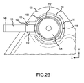
FIG. 2B illustrates a retention clip with a cam handle in an open position, in accordance with various embodiments; -
FIG. 2C illustrates a retention clip in an open position with a pin being removed or installed, in accordance with various embodiments; and -
FIG. 3 illustrates a retention clip holding a pin in place to secure a reverse-thrust actuator, in accordance with various embodiments. - The detailed description of exemplary embodiments herein makes reference to the accompanying drawings, which show exemplary embodiments by way of illustration. While these exemplary embodiments are described in sufficient detail to enable those skilled in the art to practice the exemplary embodiments of the disclosure, it should be understood that other embodiments may be realized and that logical changes and adaptations in design and construction may be made in accordance with this disclosure and the teachings herein. Thus, the detailed description herein is presented for purposes of illustration only and not limitation. The scope of the disclosure is defined by the appended claims. For example, the steps recited in any of the method or process descriptions may be executed in any order and are not necessarily limited to the order presented.
- Furthermore, any reference to singular includes plural embodiments, and any reference to more than one component or step may include a singular embodiment or step. Also, any reference to attached, fixed, connected or the like may include permanent, removable, temporary, partial, full and/or any other possible attachment option. Additionally, any reference to without contact (or similar phrases) may also include reduced contact or minimal contact. Surface shading lines may be used throughout the figures to denote different parts but not necessarily to denote the same or different materials.
- The retention clip of the present disclosure may remain attached to a housing while in the open or closed position. As a result, the retention clip is unlikely to be lost or dropped when moved between open and closed positions. Furthermore, the retention clip may be opened without tools by utilizing an integrated handle and/or human hands. As a result, the complexity and time cost of changing components retained by the retention clip may be reduced.
- With reference to
FIG. 1A , aretention clip 100 is shown inhousing 102 holdingpin 104 in place, in accordance with various embodiments.Housing 102 may be formed integrally with mounting fitting 108.Pin 104 may be inserted intohousing 102 and may slide into and outhousing 102 through the circular opening in a direction orthogonal to the x and y axes.Housing 102 may have a circular opening bored through mounting fitting 108 forpin 104 to pass intohousing 102 and project out mounting fitting 108. In that regard, pin 104 may hold a component (e.g., an actuator) in place by projecting into the component with a head (illustrated below inFIG. 3 ) ofpin 104 retained inhousing 102. - In various embodiments,
retention clip 100 may comprise ahandle section 110.Handle section 110 may project outward fromhousing 102.Handle section 110 may be configured to enable a human finger, screwdriver, lever, or clip to engageretention clip 100 and press betweenhandle section 110 andhousing 102. In that regard, handlesection 110 allows a user to openclip 100 by applying force toretention clip 100 throughhandle section 110.Handle section 110 may be disposed outside a boundary ofhousing 102 with a portion ofretention clip 100 extending inside a perimeter ofhousing 102 to formelbow sections 112 ofretention clip 100. The perimeter ofhousing 102 may be defined by a circle in the xy plane.Retention clip 100 may comprise twoelbow sections 112 disposed inside a perimeter ofhousing 102 to partially coverpin 104 whenretention clip 100 is in the closed position. In that regard, pin 104 may contactelbow sections 112 ofretention clip 100 and be restrained from motion orthogonal to the x and y axes housing 102 byelbow sections 112, which obstruct the opening ofhousing 102. Thus,elbow sections 112 ofretention clip 100 tend to retainpin 104 withinhousing 102.Body section 114 ofretention clip 100 extends between elbow section 112 (extending inside the perimeter of housing 102) and spring section 116 (disposed outside the perimeter of housing 102). - In various embodiments,
spring section 116 ofretention clip 100 may be disposed outside a perimeter ofhousing 102 on the opposite side ofhousing 102 fromhandle section 110.Spring section 116 may comprise anopening 118 completely throughretention clip 100, makingretention clip 100 discontinuous. Opening 118 may be defined by two adjacent ends ofretention clip 100 inspring section 116.Opening 118 allows easy installation ofretention clip 100 in a more flexible state. Opening 118 inspring section 116 may be small such that edges inspring section 116 definingopening 118 may be in contact whenretention clip 100 is in a closed position. In various embodiments, opening 118 ofretention clip 100 may be closed through, e.g. a weld, after installation or left open for easy replacement. Opening 118 may correspond with a contact point ofspring section 116 against the outer perimeter ofhousing 102.Spring section 116 may extend from a joint withbody section 114 towardshandle section 110. Thus, the contact point (i.e., a central portion) ofspring section 116 may be the closest portion ofspring section 116 to handlesection 110 as a result ofretention clip 100 being in a closed position.Spring section 116 biases handlesection 110 ofretention clip 100 inward (i.e., towards spring section 116) so thatretention clip 100 is held tight in the closed position (i.e., withelbow section 112 obstructing the opening of housing 102). Thus,spring section 116 may provide tension inretention clip 100 that presses againsthousing 102 in the closed position to retainretention clip 100 onhousing 102.Retention clip 102 may be spring biased in the closed position to reduce vibration during use. In that regard,spring section 116 may be formed to converge towardshandle section 110 asspring section 116 extends frombody section 114. - In various embodiments,
retention clip 100 may be made from metal (e.g., steel).Retention clip 100 may be made by bending a metal bar into the desired shape, for example. The spring constant ofretention clip 100 may be increased by increasing the cross-sectional area ofretention clip 100. Retention clip may also include a substantially constant cross sectional area throughhandle section 110,elbow section 112,body section 114, andspring section 116. For example,retention clip 100 may comprise a diameter of approximately 2.5 mm (0.1 inches) and a cross sectional area of 4.9 square mm (0.007 square inches). - With reference to
FIG. 1B , aretention clip 100 is shown in an open position inhousing 102, clearing a path to removepin 104 in a direction orthogonal to the xy plane.Handle section 110 ofretention clip 100 is moved away fromhousing 102 by applying a force F to handlesection 110.Handle section 110 exerts a tension onelbow section 112 that pullselbow section 112 towardshandle section 110. In response to force F,elbow section 112 deforms and moves towardhandle section 110.Elbow section 112 exerts tension onbody section 114 and pullsbody section 114 in the direction ofhandle section 110.Body section 114 exerts compression onspring section 116 and elastically deforms (ie., flexes)spring section 116 so that the bend betweenbody section 114 andspring section 116 may move towardshandle section 110. The contact point ofspring section 116 againsthousing 102 may remain at substantially the same point againsthousing 102. In embodiments whereopening 118 is not closed, as inFIG. 1B , then opening 118 may expand slightly in response to a force exerted by flexingspring section 116. -
Elbow section 112 and other portions ofretention clip 100 may no longer coverpin 104 inhousing 102 in response toretention clip 100 being in an open position. Stated another way, the entire outer perimeter ofpin 104 may be unobstructed byretention clip 100 when looking down the opening defined by bore ofhousing 102. Thus, whenretention clip 100 is in an open position, an exit/entry path inhousing 102 forpin 104 to be inserted and/or removed fromhousing 102 is created. In that regard, whenretention clip 100 is in the open position, insertion or removal ofpin 104 may be possible. - In various embodiments, and with reference to
FIG. 2A , aretention clip 100 with acam handle 140 is shown in a closed position similar to the closed position ofFIG. 1A . Cam handle 140 is attached athandle section 110 ofretention clip 100. Cam handle 140 may include a visual indicator thatretention clip 100 is in the closed position. In that regard, cam handle 140 may include high-visibility indicator 142 of a different color than cam handle 140. For example, high-visibility indicator 142 may comprise yellow stripes against a black backdrop. - With reference to
FIG. 2B , aretention clip 100 with cam handle 140 is shown in an open position similar to the open position ofFIG. 1B .Cam 152 of cam handle 140 comprises an opening through which handlesection 110 ofretention clip 100 travels. In that regard, handlesection 110 defines an axis of rotation that cam handle 140 turns about between the open and closed positions. The axis of rotation defined byhandle section 110 extends in the y direction. Cam handle 140 may be rotated aroundhandle section 110 ofretention clip 100 withcam 152 pressing againsthousing 102 and cam handle 140 moving away fromspring section 116 ofretention clip 100. Thus,cam 152 of cam handle 140 translates the angular motion of cam handle 140 (rotating around the axis extending in the y direction) into linear motion of handle section 110 (in the x direction).Handle section 110 is pulled away fromspring section 116 to translateelbow section 112 in the direction ofhandle section 110 and open entry/exit path to insert and/or removepin 104 is created. - In various embodiments, cam handle 140 may comprise a
warning indicator 150. When cam handle 140 is in an open position, awarning indicator 150 may be visible to indicate thatretention clip 100 is open. For example, warningindicator 150 may be a red surface that contrasts with high-visibility indicator 142 (indicating the retention clip is closed inFIG 2A ). The contrast betweenwarning indicator 150 and high-visibility indicator 142 enables easy determination of whetherretention clip 100 is in an open or closed position. - With reference to
FIG. 2C , a perspective view ofretention clip 100 in an open position is shown withpin 104 being inserted and/or removed fromhousing 102, in accordance with various embodiments. Opening 160 incam 152 provides an opening forhandle section 110 to pass throughcam 152. Opening 160 may act as a hinge for cam handle 140 to rotate around handle section 110 (as shown inFIG. 2B ). - In various embodiments,
housing 102 definesslots 162.Slots 162 ofhousing 102 may be configured to receiveelbow section 112 ofretention clip 100.Slots 162 may extend partially around a surface defining the opening ofhousing 102.Elbow section 112 ofretention clip 100 in a closed position may tend to block the opening ofhousing 102 by moving further intoslot 162 than whenretention clip 100 is in the open position. Whenretention clip 100 is in an open position,elbow section 112 may tend to leave opening ofhousing 102 unobstructed by moving further outslot 162 than whenretention clip 100 is in the closed position. A first elbow section may be disposed on a first side ofhousing 102 while a second elbow section is disposed on a second side ofhousing 102 opposite the first housing. The first andsecond elbow sections 112 may be symmetric about an axis extending in the x direction half way between the first andsecond elbow sections 112. - In various embodiments, the opening defined by
housing 102 may terminate atlip 166.Lip 166 may have aninner diameter 164 that allows a portion ofpin 104 to extend throughhousing 102. When inserted intohousing 102,pin 104 may include a head to press againstlip 166 with a portion ofpin 104 extending throughinner diameter 164. - With reference to
FIG. 3 , a reverse-thrust actuator 182 is shown mounted on mounting fitting 180, in accordance with various embodiments. Mounting fitting 180 compriseshousing 102 withretention clip 100 installed on housing 102 (as shown in greater detail inFIG. 2A ).Pin 104 may be inserted inhousing 102 of mounting fitting 180.Retention pin 104 may extend through mounting fitting 180 and into reverse-thrust actuator 182. A similar pin, clip, and housing may be implemented on the other side of reverse-thrust actuator 182 so that two pins may fix reverse-thrust actuator 182 in place. Althoughpin 104,housing 102, andretention clip 100 are shown securing reverse-thrust actuator 182 to mounting fitting 180,retention clip 100 may secure any pin or other component where fast and easy replacement is desired. Theretention clip 100 has been illustrated in use to retainpin 104 for a thrust reverser actuator, but ofcourse retention clip 100 can be used in many other environments. In various embodiments, asingle pin 104 or any number ofpins 104 may be used to hold a component in place usingretention clip 100 andhousing 102. - Benefits and other advantages have been described herein with regard to specific embodiments. Furthermore, the connecting lines shown in the various figures contained herein are intended to represent exemplary functional relationships and/or physical couplings between the various elements. It should be noted that many alternative or additional functional relationships or physical connections may be present in a practical system. However, the benefits, advantages, and any elements that may cause any benefit or advantage to occur or become more pronounced are not to be construed as critical, required, or essential features or elements of the disclosure. The scope of the disclosure is accordingly to be limited by nothing other than the appended claims, in which reference to an element in the singular is not intended to mean "one and only one" unless explicitly so stated, but rather "one or more." Moreover, where a phrase similar to "at least one of A, B, or C" is used in the claims, it is intended that the phrase be interpreted to mean that A alone may be present in an embodiment, B alone may be present in an embodiment, C alone may be present in an embodiment, or that any combination of the elements A, B and C may be present in a single embodiment; for example, A and B, A and C, B and C, or A and B and C.
- Systems, methods and apparatus are provided herein. In the detailed description herein, references to "various embodiments", "one embodiment", "an embodiment", "an example embodiment", etc., indicate that the embodiment described may include a particular feature, structure, or characteristic, but every embodiment may not necessarily include the particular feature, structure, or characteristic. Moreover, such phrases are not necessarily referring to the same embodiment. Further, when a particular feature, structure, or characteristic is described in connection with an embodiment, it is submitted that it is within the knowledge of one skilled in the art to affect such feature, structure, or characteristic in connection with other embodiments whether or not explicitly described. After reading the description, it will be apparent to one skilled in the relevant art(s) how to implement the disclosure in alternative embodiments.
Claims (15)
- A retention clip (100), comprising:a spring section (116);a first elbow section (112) extending from the spring section (116);a handle section (110) extending from the first elbow section (112);a second elbow section opposite the first elbow section (112), the second elbow section extending between the handle section (110) and the spring section (116).
- The retention clip of claim 1, further comprising a cam handle (140) configured to rotate about the handle section (110).
- The retention clip of claim 2, wherein the cam handle (140) comprises a visual indicator (142) configured to indicate whether the cam handle (140) is in a closed position.
- The retention clip of claim 1, 2 or 3, further comprising an opening (118) defined by the spring section (116).
- The retention clip of any preceding claim, wherein the spring section (116) is configured to load in response to a force applied to the handle section (110).
- The retention clip of any preceding claim, wherein a central portion of the spring section (116) is closest to the handle section (110) as a result of the retention clip (100) being in a closed position.
- A retention assembly, comprising:a mounting fitting (108);a housing (102) disposed in the mounting fitting (108) and defining a perimeter of an opening; anda retention clip (100) disposed around the housing (102) and comprising an elbow section (112) extending into the perimeter to obstruct the opening.
- The retention assembly of claim 7, wherein the housing (102) defines a slot (162) and wherein the elbow section (112) extends into the slot (162).
- The retention clip of claim 8, further comprising a handle section (110) extending from to the elbow section (112) and configured to move the elbow section (112) relative to the slot (162).
- The retention assembly of claim 9, further comprising a cam handle (140) configured to rotate about the handle section (110).
- The retention assembly of claim 10, wherein the cam handle (140) comprises a visual indicator (142) configured to indicate whether the cam handle (140) is in a closed position.
- The retention assembly of claim 9, 10 or 11, further comprising a spring section (116) extending from the elbow section (112).
- The retention clip of claim 12, wherein the spring section (116) is discontinuous.
- The retention clip of claim 12 or 13, wherein the spring section (116) is configured to load in response to a force applied to the handle section (110).
- The retention clip of any of claims 7 to 14, further comprising a pin (104) disposed in the housing (102) and held within the opening by the retention clip (100).
Applications Claiming Priority (1)
| Application Number | Priority Date | Filing Date | Title |
|---|---|---|---|
| US14/546,559 US9695863B2 (en) | 2014-11-18 | 2014-11-18 | Clip for pin retention |
Publications (2)
| Publication Number | Publication Date |
|---|---|
| EP3023648A1 true EP3023648A1 (en) | 2016-05-25 |
| EP3023648B1 EP3023648B1 (en) | 2020-01-01 |
Family
ID=54695465
Family Applications (1)
| Application Number | Title | Priority Date | Filing Date |
|---|---|---|---|
| EP15194520.1A Active EP3023648B1 (en) | 2014-11-18 | 2015-11-13 | Clip for pin retention |
Country Status (2)
| Country | Link |
|---|---|
| US (1) | US9695863B2 (en) |
| EP (1) | EP3023648B1 (en) |
Families Citing this family (4)
| Publication number | Priority date | Publication date | Assignee | Title |
|---|---|---|---|---|
| EP3243963B1 (en) * | 2016-05-10 | 2018-07-04 | BAUER Deep Drilling GmbH | Assembly and method for connecting a hydraulic cylinder |
| CN110319095A (en) * | 2019-07-16 | 2019-10-11 | 航天精工股份有限公司 | A kind of clamping panel fastening assembly |
| CN111677735A (en) * | 2020-06-18 | 2020-09-18 | 沈阳远程摩擦密封材料有限公司 | A kind of circlip for powder metallurgy brake |
| CN112109535B (en) * | 2020-08-25 | 2022-02-01 | 东风汽车集团有限公司 | Battery locking mechanism |
Citations (3)
| Publication number | Priority date | Publication date | Assignee | Title |
|---|---|---|---|---|
| GB987717A (en) * | 1961-12-06 | 1965-03-31 | Fibora A G | Improvements in lock-nuts |
| US20070071578A1 (en) * | 2005-09-20 | 2007-03-29 | Piolax, Inc. | Shaft fixing clip and shaft fixing structure using the clip |
| US20130319172A1 (en) * | 2011-01-28 | 2013-12-05 | Gmt Gummi-Metall-Technik Gmbh | Securing clip comprising a locking mechanism |
Family Cites Families (7)
| Publication number | Priority date | Publication date | Assignee | Title |
|---|---|---|---|---|
| US1513710A (en) * | 1924-01-28 | 1924-10-28 | Autoyre Company | Separable fastener |
| US1782196A (en) * | 1928-02-10 | 1930-11-18 | Dalton Hubert | Threadless nut or collar |
| US2646713A (en) * | 1950-01-10 | 1953-07-28 | William E Summerbell | Threadless retainer |
| US3314696A (en) * | 1964-02-11 | 1967-04-18 | Perfecting Service Company | Quick connect coupling |
| US3534988A (en) * | 1968-11-15 | 1970-10-20 | Ite Imperial Corp | Tube end mounted sleeve |
| US4244608A (en) * | 1979-03-05 | 1981-01-13 | The Gates Rubber Company | Female coupling with staple lock |
| US7278693B2 (en) * | 2005-08-02 | 2007-10-09 | The Scott Fetzer Company | Coupling assembly |
-
2014
- 2014-11-18 US US14/546,559 patent/US9695863B2/en active Active
-
2015
- 2015-11-13 EP EP15194520.1A patent/EP3023648B1/en active Active
Patent Citations (3)
| Publication number | Priority date | Publication date | Assignee | Title |
|---|---|---|---|---|
| GB987717A (en) * | 1961-12-06 | 1965-03-31 | Fibora A G | Improvements in lock-nuts |
| US20070071578A1 (en) * | 2005-09-20 | 2007-03-29 | Piolax, Inc. | Shaft fixing clip and shaft fixing structure using the clip |
| US20130319172A1 (en) * | 2011-01-28 | 2013-12-05 | Gmt Gummi-Metall-Technik Gmbh | Securing clip comprising a locking mechanism |
Also Published As
| Publication number | Publication date |
|---|---|
| US9695863B2 (en) | 2017-07-04 |
| US20160138643A1 (en) | 2016-05-19 |
| EP3023648B1 (en) | 2020-01-01 |
Similar Documents
| Publication | Publication Date | Title |
|---|---|---|
| EP3023648B1 (en) | Clip for pin retention | |
| US3984191A (en) | Captive spring clip | |
| JP6576332B2 (en) | Turbomachinery case with endoscopic opening | |
| KR100889959B1 (en) | wiper blade | |
| US10072685B2 (en) | Clip holding and release device | |
| EP3212946B1 (en) | Retaining device, in particular for removably connecting vehicle body parts | |
| EP2109720B1 (en) | Self-retaining anti-rotation clip and spherical-bearing rod end comprising such a clip | |
| EP3366424A1 (en) | Quick detachable and adjustable magnetic seat for sleeve | |
| EP3998010B1 (en) | Self-locking device for endoscope | |
| CN106110535A (en) | The fixture on the rope of cam is loaded equipped with the spring improved | |
| EP2726750B1 (en) | Spherical plain bearing with constant torque | |
| WO2017199718A1 (en) | Locking mechanism for tubular body | |
| US2156110A (en) | Flush cover access opening | |
| EP3020999B1 (en) | Aircraft brake puck assembly | |
| KR101060366B1 (en) | Air conditioner | |
| EP2943712B1 (en) | Lever quick connect intercom fitting | |
| JP2007054715A (en) | Element exchange type filter | |
| US20210040963A1 (en) | Rod end cover | |
| KR20160068923A (en) | Windshield wiper device | |
| US1949027A (en) | Airplane cowl fastener | |
| US1594776A (en) | Cowling and the like for aircraft and other structures | |
| CA2994115C (en) | Bearing race and seal driver handle | |
| WO2016064746A1 (en) | Inspection device and method for use | |
| JP5541200B2 (en) | Split snap ring tool | |
| EP3112703B1 (en) | Diaper pin vibration damper |
Legal Events
| Date | Code | Title | Description |
|---|---|---|---|
| AK | Designated contracting states |
Kind code of ref document: A1 Designated state(s): AL AT BE BG CH CY CZ DE DK EE ES FI FR GB GR HR HU IE IS IT LI LT LU LV MC MK MT NL NO PL PT RO RS SE SI SK SM TR |
|
| AX | Request for extension of the european patent |
Extension state: BA ME |
|
| PUAI | Public reference made under article 153(3) epc to a published international application that has entered the european phase |
Free format text: ORIGINAL CODE: 0009012 |
|
| STAA | Information on the status of an ep patent application or granted ep patent |
Free format text: STATUS: REQUEST FOR EXAMINATION WAS MADE |
|
| 17P | Request for examination filed |
Effective date: 20161124 |
|
| RBV | Designated contracting states (corrected) |
Designated state(s): AL AT BE BG CH CY CZ DE DK EE ES FI FR GB GR HR HU IE IS IT LI LT LU LV MC MK MT NL NO PL PT RO RS SE SI SK SM TR |
|
| GRAJ | Information related to disapproval of communication of intention to grant by the applicant or resumption of examination proceedings by the epo deleted |
Free format text: ORIGINAL CODE: EPIDOSDIGR1 |
|
| GRAP | Despatch of communication of intention to grant a patent |
Free format text: ORIGINAL CODE: EPIDOSNIGR1 |
|
| GRAP | Despatch of communication of intention to grant a patent |
Free format text: ORIGINAL CODE: EPIDOSNIGR1 |
|
| STAA | Information on the status of an ep patent application or granted ep patent |
Free format text: STATUS: GRANT OF PATENT IS INTENDED |
|
| RIC1 | Information provided on ipc code assigned before grant |
Ipc: F16B 21/18 20060101ALI20190607BHEP Ipc: F16B 1/00 20060101ALN20190607BHEP Ipc: F16B 2/24 20060101AFI20190607BHEP |
|
| INTG | Intention to grant announced |
Effective date: 20190716 |
|
| GRAS | Grant fee paid |
Free format text: ORIGINAL CODE: EPIDOSNIGR3 |
|
| GRAA | (expected) grant |
Free format text: ORIGINAL CODE: 0009210 |
|
| STAA | Information on the status of an ep patent application or granted ep patent |
Free format text: STATUS: THE PATENT HAS BEEN GRANTED |
|
| AK | Designated contracting states |
Kind code of ref document: B1 Designated state(s): AL AT BE BG CH CY CZ DE DK EE ES FI FR GB GR HR HU IE IS IT LI LT LU LV MC MK MT NL NO PL PT RO RS SE SI SK SM TR |
|
| REG | Reference to a national code |
Ref country code: GB Ref legal event code: FG4D |
|
| REG | Reference to a national code |
Ref country code: CH Ref legal event code: EP Ref country code: AT Ref legal event code: REF Ref document number: 1220114 Country of ref document: AT Kind code of ref document: T Effective date: 20200115 |
|
| REG | Reference to a national code |
Ref country code: IE Ref legal event code: FG4D |
|
| REG | Reference to a national code |
Ref country code: DE Ref legal event code: R096 Ref document number: 602015044564 Country of ref document: DE |
|
| REG | Reference to a national code |
Ref country code: NL Ref legal event code: MP Effective date: 20200101 |
|
| REG | Reference to a national code |
Ref country code: LT Ref legal event code: MG4D |
|
| PG25 | Lapsed in a contracting state [announced via postgrant information from national office to epo] |
Ref country code: CZ Free format text: LAPSE BECAUSE OF FAILURE TO SUBMIT A TRANSLATION OF THE DESCRIPTION OR TO PAY THE FEE WITHIN THE PRESCRIBED TIME-LIMIT Effective date: 20200101 Ref country code: LT Free format text: LAPSE BECAUSE OF FAILURE TO SUBMIT A TRANSLATION OF THE DESCRIPTION OR TO PAY THE FEE WITHIN THE PRESCRIBED TIME-LIMIT Effective date: 20200101 Ref country code: NL Free format text: LAPSE BECAUSE OF FAILURE TO SUBMIT A TRANSLATION OF THE DESCRIPTION OR TO PAY THE FEE WITHIN THE PRESCRIBED TIME-LIMIT Effective date: 20200101 Ref country code: PT Free format text: LAPSE BECAUSE OF FAILURE TO SUBMIT A TRANSLATION OF THE DESCRIPTION OR TO PAY THE FEE WITHIN THE PRESCRIBED TIME-LIMIT Effective date: 20200527 Ref country code: RS Free format text: LAPSE BECAUSE OF FAILURE TO SUBMIT A TRANSLATION OF THE DESCRIPTION OR TO PAY THE FEE WITHIN THE PRESCRIBED TIME-LIMIT Effective date: 20200101 Ref country code: NO Free format text: LAPSE BECAUSE OF FAILURE TO SUBMIT A TRANSLATION OF THE DESCRIPTION OR TO PAY THE FEE WITHIN THE PRESCRIBED TIME-LIMIT Effective date: 20200401 Ref country code: FI Free format text: LAPSE BECAUSE OF FAILURE TO SUBMIT A TRANSLATION OF THE DESCRIPTION OR TO PAY THE FEE WITHIN THE PRESCRIBED TIME-LIMIT Effective date: 20200101 |
|
| PG25 | Lapsed in a contracting state [announced via postgrant information from national office to epo] |
Ref country code: IS Free format text: LAPSE BECAUSE OF FAILURE TO SUBMIT A TRANSLATION OF THE DESCRIPTION OR TO PAY THE FEE WITHIN THE PRESCRIBED TIME-LIMIT Effective date: 20200501 Ref country code: BG Free format text: LAPSE BECAUSE OF FAILURE TO SUBMIT A TRANSLATION OF THE DESCRIPTION OR TO PAY THE FEE WITHIN THE PRESCRIBED TIME-LIMIT Effective date: 20200401 Ref country code: GR Free format text: LAPSE BECAUSE OF FAILURE TO SUBMIT A TRANSLATION OF THE DESCRIPTION OR TO PAY THE FEE WITHIN THE PRESCRIBED TIME-LIMIT Effective date: 20200402 Ref country code: SE Free format text: LAPSE BECAUSE OF FAILURE TO SUBMIT A TRANSLATION OF THE DESCRIPTION OR TO PAY THE FEE WITHIN THE PRESCRIBED TIME-LIMIT Effective date: 20200101 Ref country code: LV Free format text: LAPSE BECAUSE OF FAILURE TO SUBMIT A TRANSLATION OF THE DESCRIPTION OR TO PAY THE FEE WITHIN THE PRESCRIBED TIME-LIMIT Effective date: 20200101 Ref country code: HR Free format text: LAPSE BECAUSE OF FAILURE TO SUBMIT A TRANSLATION OF THE DESCRIPTION OR TO PAY THE FEE WITHIN THE PRESCRIBED TIME-LIMIT Effective date: 20200101 |
|
| REG | Reference to a national code |
Ref country code: DE Ref legal event code: R097 Ref document number: 602015044564 Country of ref document: DE |
|
| PG25 | Lapsed in a contracting state [announced via postgrant information from national office to epo] |
Ref country code: DK Free format text: LAPSE BECAUSE OF FAILURE TO SUBMIT A TRANSLATION OF THE DESCRIPTION OR TO PAY THE FEE WITHIN THE PRESCRIBED TIME-LIMIT Effective date: 20200101 Ref country code: ES Free format text: LAPSE BECAUSE OF FAILURE TO SUBMIT A TRANSLATION OF THE DESCRIPTION OR TO PAY THE FEE WITHIN THE PRESCRIBED TIME-LIMIT Effective date: 20200101 Ref country code: EE Free format text: LAPSE BECAUSE OF FAILURE TO SUBMIT A TRANSLATION OF THE DESCRIPTION OR TO PAY THE FEE WITHIN THE PRESCRIBED TIME-LIMIT Effective date: 20200101 Ref country code: SM Free format text: LAPSE BECAUSE OF FAILURE TO SUBMIT A TRANSLATION OF THE DESCRIPTION OR TO PAY THE FEE WITHIN THE PRESCRIBED TIME-LIMIT Effective date: 20200101 Ref country code: SK Free format text: LAPSE BECAUSE OF FAILURE TO SUBMIT A TRANSLATION OF THE DESCRIPTION OR TO PAY THE FEE WITHIN THE PRESCRIBED TIME-LIMIT Effective date: 20200101 Ref country code: RO Free format text: LAPSE BECAUSE OF FAILURE TO SUBMIT A TRANSLATION OF THE DESCRIPTION OR TO PAY THE FEE WITHIN THE PRESCRIBED TIME-LIMIT Effective date: 20200101 |
|
| PLBE | No opposition filed within time limit |
Free format text: ORIGINAL CODE: 0009261 |
|
| STAA | Information on the status of an ep patent application or granted ep patent |
Free format text: STATUS: NO OPPOSITION FILED WITHIN TIME LIMIT |
|
| REG | Reference to a national code |
Ref country code: AT Ref legal event code: MK05 Ref document number: 1220114 Country of ref document: AT Kind code of ref document: T Effective date: 20200101 |
|
| 26N | No opposition filed |
Effective date: 20201002 |
|
| PG25 | Lapsed in a contracting state [announced via postgrant information from national office to epo] |
Ref country code: IT Free format text: LAPSE BECAUSE OF FAILURE TO SUBMIT A TRANSLATION OF THE DESCRIPTION OR TO PAY THE FEE WITHIN THE PRESCRIBED TIME-LIMIT Effective date: 20200101 Ref country code: AT Free format text: LAPSE BECAUSE OF FAILURE TO SUBMIT A TRANSLATION OF THE DESCRIPTION OR TO PAY THE FEE WITHIN THE PRESCRIBED TIME-LIMIT Effective date: 20200101 |
|
| PG25 | Lapsed in a contracting state [announced via postgrant information from national office to epo] |
Ref country code: PL Free format text: LAPSE BECAUSE OF FAILURE TO SUBMIT A TRANSLATION OF THE DESCRIPTION OR TO PAY THE FEE WITHIN THE PRESCRIBED TIME-LIMIT Effective date: 20200101 Ref country code: SI Free format text: LAPSE BECAUSE OF FAILURE TO SUBMIT A TRANSLATION OF THE DESCRIPTION OR TO PAY THE FEE WITHIN THE PRESCRIBED TIME-LIMIT Effective date: 20200101 |
|
| PG25 | Lapsed in a contracting state [announced via postgrant information from national office to epo] |
Ref country code: MC Free format text: LAPSE BECAUSE OF FAILURE TO SUBMIT A TRANSLATION OF THE DESCRIPTION OR TO PAY THE FEE WITHIN THE PRESCRIBED TIME-LIMIT Effective date: 20200101 |
|
| REG | Reference to a national code |
Ref country code: CH Ref legal event code: PL |
|
| PG25 | Lapsed in a contracting state [announced via postgrant information from national office to epo] |
Ref country code: LU Free format text: LAPSE BECAUSE OF NON-PAYMENT OF DUE FEES Effective date: 20201113 |
|
| REG | Reference to a national code |
Ref country code: BE Ref legal event code: MM Effective date: 20201130 |
|
| PG25 | Lapsed in a contracting state [announced via postgrant information from national office to epo] |
Ref country code: LI Free format text: LAPSE BECAUSE OF NON-PAYMENT OF DUE FEES Effective date: 20201130 Ref country code: CH Free format text: LAPSE BECAUSE OF NON-PAYMENT OF DUE FEES Effective date: 20201130 |
|
| PG25 | Lapsed in a contracting state [announced via postgrant information from national office to epo] |
Ref country code: IE Free format text: LAPSE BECAUSE OF NON-PAYMENT OF DUE FEES Effective date: 20201113 |
|
| PG25 | Lapsed in a contracting state [announced via postgrant information from national office to epo] |
Ref country code: TR Free format text: LAPSE BECAUSE OF FAILURE TO SUBMIT A TRANSLATION OF THE DESCRIPTION OR TO PAY THE FEE WITHIN THE PRESCRIBED TIME-LIMIT Effective date: 20200101 Ref country code: MT Free format text: LAPSE BECAUSE OF FAILURE TO SUBMIT A TRANSLATION OF THE DESCRIPTION OR TO PAY THE FEE WITHIN THE PRESCRIBED TIME-LIMIT Effective date: 20200101 Ref country code: CY Free format text: LAPSE BECAUSE OF FAILURE TO SUBMIT A TRANSLATION OF THE DESCRIPTION OR TO PAY THE FEE WITHIN THE PRESCRIBED TIME-LIMIT Effective date: 20200101 |
|
| PG25 | Lapsed in a contracting state [announced via postgrant information from national office to epo] |
Ref country code: MK Free format text: LAPSE BECAUSE OF FAILURE TO SUBMIT A TRANSLATION OF THE DESCRIPTION OR TO PAY THE FEE WITHIN THE PRESCRIBED TIME-LIMIT Effective date: 20200101 Ref country code: AL Free format text: LAPSE BECAUSE OF FAILURE TO SUBMIT A TRANSLATION OF THE DESCRIPTION OR TO PAY THE FEE WITHIN THE PRESCRIBED TIME-LIMIT Effective date: 20200101 |
|
| PG25 | Lapsed in a contracting state [announced via postgrant information from national office to epo] |
Ref country code: BE Free format text: LAPSE BECAUSE OF NON-PAYMENT OF DUE FEES Effective date: 20201130 |
|
| PGFP | Annual fee paid to national office [announced via postgrant information from national office to epo] |
Ref country code: DE Payment date: 20251022 Year of fee payment: 11 |
|
| PGFP | Annual fee paid to national office [announced via postgrant information from national office to epo] |
Ref country code: GB Payment date: 20251023 Year of fee payment: 11 |
|
| PGFP | Annual fee paid to national office [announced via postgrant information from national office to epo] |
Ref country code: FR Payment date: 20251022 Year of fee payment: 11 |
|
| P01 | Opt-out of the competence of the unified patent court (upc) registered |
Free format text: CASE NUMBER: UPC_APP_0016902_3023648/2025 Effective date: 20251210 |