EP3023635A1 - Système et procédé de surveillance et de contrôle de déflexion de pale d'éolienne - Google Patents
Système et procédé de surveillance et de contrôle de déflexion de pale d'éolienne Download PDFInfo
- Publication number
- EP3023635A1 EP3023635A1 EP15194067.3A EP15194067A EP3023635A1 EP 3023635 A1 EP3023635 A1 EP 3023635A1 EP 15194067 A EP15194067 A EP 15194067A EP 3023635 A1 EP3023635 A1 EP 3023635A1
- Authority
- EP
- European Patent Office
- Prior art keywords
- wind
- loading
- wind turbine
- condition
- threshold
- Prior art date
- Legal status (The legal status is an assumption and is not a legal conclusion. Google has not performed a legal analysis and makes no representation as to the accuracy of the status listed.)
- Granted
Links
- 238000000034 method Methods 0.000 title claims abstract description 41
- 238000012544 monitoring process Methods 0.000 title claims abstract description 26
- 238000011068 loading method Methods 0.000 claims abstract description 81
- 230000009471 action Effects 0.000 claims abstract description 24
- 230000004044 response Effects 0.000 claims abstract description 12
- 230000001133 acceleration Effects 0.000 claims description 19
- 238000012876 topography Methods 0.000 claims description 5
- 230000006870 function Effects 0.000 description 9
- 230000008859 change Effects 0.000 description 6
- 230000008901 benefit Effects 0.000 description 4
- 238000010586 diagram Methods 0.000 description 4
- 230000007246 mechanism Effects 0.000 description 4
- 230000003213 activating effect Effects 0.000 description 3
- 238000005452 bending Methods 0.000 description 3
- 230000004048 modification Effects 0.000 description 3
- 238000012986 modification Methods 0.000 description 3
- 230000008878 coupling Effects 0.000 description 2
- 238000010168 coupling process Methods 0.000 description 2
- 238000005859 coupling reaction Methods 0.000 description 2
- 230000007613 environmental effect Effects 0.000 description 2
- 238000012546 transfer Methods 0.000 description 2
- 206010036086 Polymenorrhoea Diseases 0.000 description 1
- 229910000831 Steel Inorganic materials 0.000 description 1
- 238000010276 construction Methods 0.000 description 1
- 230000007423 decrease Effects 0.000 description 1
- 230000003247 decreasing effect Effects 0.000 description 1
- 238000001514 detection method Methods 0.000 description 1
- 239000011888 foil Substances 0.000 description 1
- 230000006872 improvement Effects 0.000 description 1
- 239000000463 material Substances 0.000 description 1
- 230000007935 neutral effect Effects 0.000 description 1
- 230000008439 repair process Effects 0.000 description 1
- 239000010959 steel Substances 0.000 description 1
Images


Classifications
-
- F—MECHANICAL ENGINEERING; LIGHTING; HEATING; WEAPONS; BLASTING
- F03—MACHINES OR ENGINES FOR LIQUIDS; WIND, SPRING, OR WEIGHT MOTORS; PRODUCING MECHANICAL POWER OR A REACTIVE PROPULSIVE THRUST, NOT OTHERWISE PROVIDED FOR
- F03D—WIND MOTORS
- F03D7/00—Controlling wind motors
- F03D7/02—Controlling wind motors the wind motors having rotation axis substantially parallel to the air flow entering the rotor
- F03D7/028—Controlling wind motors the wind motors having rotation axis substantially parallel to the air flow entering the rotor controlling wind motor output power
- F03D7/0288—Controlling wind motors the wind motors having rotation axis substantially parallel to the air flow entering the rotor controlling wind motor output power in relation to clearance between the blade and the tower, i.e. preventing tower strike
-
- F—MECHANICAL ENGINEERING; LIGHTING; HEATING; WEAPONS; BLASTING
- F03—MACHINES OR ENGINES FOR LIQUIDS; WIND, SPRING, OR WEIGHT MOTORS; PRODUCING MECHANICAL POWER OR A REACTIVE PROPULSIVE THRUST, NOT OTHERWISE PROVIDED FOR
- F03D—WIND MOTORS
- F03D17/00—Monitoring or testing of wind motors, e.g. diagnostics
-
- F—MECHANICAL ENGINEERING; LIGHTING; HEATING; WEAPONS; BLASTING
- F03—MACHINES OR ENGINES FOR LIQUIDS; WIND, SPRING, OR WEIGHT MOTORS; PRODUCING MECHANICAL POWER OR A REACTIVE PROPULSIVE THRUST, NOT OTHERWISE PROVIDED FOR
- F03D—WIND MOTORS
- F03D7/00—Controlling wind motors
- F03D7/02—Controlling wind motors the wind motors having rotation axis substantially parallel to the air flow entering the rotor
- F03D7/022—Adjusting aerodynamic properties of the blades
- F03D7/0224—Adjusting blade pitch
-
- F—MECHANICAL ENGINEERING; LIGHTING; HEATING; WEAPONS; BLASTING
- F03—MACHINES OR ENGINES FOR LIQUIDS; WIND, SPRING, OR WEIGHT MOTORS; PRODUCING MECHANICAL POWER OR A REACTIVE PROPULSIVE THRUST, NOT OTHERWISE PROVIDED FOR
- F03D—WIND MOTORS
- F03D7/00—Controlling wind motors
- F03D7/02—Controlling wind motors the wind motors having rotation axis substantially parallel to the air flow entering the rotor
- F03D7/04—Automatic control; Regulation
- F03D7/042—Automatic control; Regulation by means of an electrical or electronic controller
- F03D7/047—Automatic control; Regulation by means of an electrical or electronic controller characterised by the controller architecture, e.g. multiple processors or data communications
-
- F—MECHANICAL ENGINEERING; LIGHTING; HEATING; WEAPONS; BLASTING
- F05—INDEXING SCHEMES RELATING TO ENGINES OR PUMPS IN VARIOUS SUBCLASSES OF CLASSES F01-F04
- F05B—INDEXING SCHEME RELATING TO WIND, SPRING, WEIGHT, INERTIA OR LIKE MOTORS, TO MACHINES OR ENGINES FOR LIQUIDS COVERED BY SUBCLASSES F03B, F03D AND F03G
- F05B2270/00—Control
- F05B2270/10—Purpose of the control system
- F05B2270/17—Purpose of the control system to avoid excessive deflection of the blades
-
- F—MECHANICAL ENGINEERING; LIGHTING; HEATING; WEAPONS; BLASTING
- F05—INDEXING SCHEMES RELATING TO ENGINES OR PUMPS IN VARIOUS SUBCLASSES OF CLASSES F01-F04
- F05B—INDEXING SCHEME RELATING TO WIND, SPRING, WEIGHT, INERTIA OR LIKE MOTORS, TO MACHINES OR ENGINES FOR LIQUIDS COVERED BY SUBCLASSES F03B, F03D AND F03G
- F05B2270/00—Control
- F05B2270/30—Control parameters, e.g. input parameters
- F05B2270/32—Wind speeds
-
- F—MECHANICAL ENGINEERING; LIGHTING; HEATING; WEAPONS; BLASTING
- F05—INDEXING SCHEMES RELATING TO ENGINES OR PUMPS IN VARIOUS SUBCLASSES OF CLASSES F01-F04
- F05B—INDEXING SCHEME RELATING TO WIND, SPRING, WEIGHT, INERTIA OR LIKE MOTORS, TO MACHINES OR ENGINES FOR LIQUIDS COVERED BY SUBCLASSES F03B, F03D AND F03G
- F05B2270/00—Control
- F05B2270/30—Control parameters, e.g. input parameters
- F05B2270/322—Control parameters, e.g. input parameters the detection or prediction of a wind gust
-
- F—MECHANICAL ENGINEERING; LIGHTING; HEATING; WEAPONS; BLASTING
- F05—INDEXING SCHEMES RELATING TO ENGINES OR PUMPS IN VARIOUS SUBCLASSES OF CLASSES F01-F04
- F05B—INDEXING SCHEME RELATING TO WIND, SPRING, WEIGHT, INERTIA OR LIKE MOTORS, TO MACHINES OR ENGINES FOR LIQUIDS COVERED BY SUBCLASSES F03B, F03D AND F03G
- F05B2270/00—Control
- F05B2270/30—Control parameters, e.g. input parameters
- F05B2270/331—Mechanical loads
-
- Y—GENERAL TAGGING OF NEW TECHNOLOGICAL DEVELOPMENTS; GENERAL TAGGING OF CROSS-SECTIONAL TECHNOLOGIES SPANNING OVER SEVERAL SECTIONS OF THE IPC; TECHNICAL SUBJECTS COVERED BY FORMER USPC CROSS-REFERENCE ART COLLECTIONS [XRACs] AND DIGESTS
- Y02—TECHNOLOGIES OR APPLICATIONS FOR MITIGATION OR ADAPTATION AGAINST CLIMATE CHANGE
- Y02E—REDUCTION OF GREENHOUSE GAS [GHG] EMISSIONS, RELATED TO ENERGY GENERATION, TRANSMISSION OR DISTRIBUTION
- Y02E10/00—Energy generation through renewable energy sources
- Y02E10/70—Wind energy
- Y02E10/72—Wind turbines with rotation axis in wind direction
Definitions
- the present subject matter relates generally to wind turbines and particularly to turbine blade deflection. More particularly, the present subject matter relates to systems and methods for monitoring and controlling turbine blade deflection during operation of a wind turbine.
- a modem wind turbine typically includes a tower, a generator, a gearbox, a nacelle, and one or more turbine blades.
- the turbine blades capture kinetic energy from wind using known foil principles and transmit the kinetic energy through rotational energy to turn a shaft coupling the rotor blades to a gearbox, or if a gearbox is not used, directly to the generator.
- the generator then converts the mechanical energy to electrical energy that may be deployed to a utility grid.
- Known wind turbine systems determine turbine blade deflection by utilizing external sensors, which are typically mounted on the turbine blades or on the tower. These sensors are designed to sense turbine blade operating conditions (e.g. blade strain, blade acceleration or blade velocity) to enable blade deflection to be inferred or calculated.
- turbine blade operating conditions e.g. blade strain, blade acceleration or blade velocity
- maintaining the sensors can be very costly and calibrating such sensors can be quite complex and time consuming.
- the sensors since the sensors must be calibrated frequently, there is a concern with regard to the reliability of data transmitted from the sensors over an extended period of time.
- the present subject matter provides a unique system for monitoring and controlling the deflection of rotor blades of a wind turbine.
- the method includes operating the wind turbine at standard pitch angle settings for the rotor blades.
- Another step includes monitoring a loading condition of the wind turbine over a predetermined time period.
- a further step includes tracking a number of wind condition deviations of a certain magnitude occurring during a predetermined time period.
- the method also include altering one or more of the standard pitch settings of the rotor blades in response to the number of wind condition deviations exceeding a wind deviation threshold and/or the loading condition exceeding a loading threshold as an exceedance above the wind deviation threshold and the loading threshold indicates an increased probability of a rotor blade deflection occurring in one or more of the rotor blades.
- the method includes performing one or more additional corrective actions so as to reduce the probability of a rotor blade tower strike.
- the present disclosure is directed to a system for monitoring and controlling the deflection of rotor blades of a wind turbine.
- the system includes one or more sensors configured to monitor a loading condition of the wind turbine over a predetermined time period and a controller communicatively coupled to the one or more sensors.
- the controller is configured to perform one or more operations, including but not limited to, operating the wind turbine at standard pitch angle settings for the rotor blades, tracking a number of wind condition deviations of a certain amount occurring during a predetermined time period, altering one or more of the standard pitch settings of the rotor blades in response to the number of wind condition deviations exceeding a wind deviation threshold and/or the loading condition exceeding a loading threshold as an exceedance above the wind deviation threshold and the loading threshold indicates an increased probability of a rotor blade deflection occurring in one or more of the rotor blades, and performing one or more corrective actions so as to reduce the probability of a rotor blade tower strike.
- the present disclosure is directed to a method for preventing rotor blade tower strike of a wind turbine.
- the method includes monitoring a tower acceleration of a wind turbine tower over a predetermined time period. Another step includes tracking wind condition deviations during a predetermined time period.
- the method also includes altering one or more of the standard pitch settings of the rotor blades in response to the number of wind condition deviations exceeding a wind deviation threshold and/or the loading condition exceeding a loading threshold as an exceedance above the wind deviation threshold and the loading threshold indicates an increased probability of a rotor blade deflection occurring in one or more of the rotor blades.
- the present disclosure provides a unique system for monitoring and controlling the deflection of rotor blades of a wind turbine to reduce risk during conditions believed to be associated with blade tower strikes.
- the blade clearance control scheme of the present disclosure is activated by monitoring wind direction instability and elevated loads (based on sensing tower acceleration).
- the control scheme when the control scheme is active, an additional blade pitch offset is introduced by the existing pitch control system.
- the operational blade angles are slightly higher such that the corresponding torque, power, loads, and deflection may be reduced.
- blade edge-wise stiffness in increased by the higher pitch angles, thereby resulting in less blade deflection and more clearance with the tower during operation. Accordingly, the altered pitch angle affect conditions when the blade typically deflects the most, i.e. at mid-level wind speed conditions.
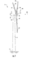
- FIG. 1 illustrates a perspective view of a horizontal-axis wind turbine 10.
- the wind turbine 10 includes a tower 12 that extends from a support system 14, a nacelle 16 mounted on the tower 12, and a rotor 18 that is coupled to the nacelle 16.
- the rotor 18 includes a rotatable hub 20 and at least one turbine blade 22 coupled to and extending outward from the hub 20.
- the rotor 18 includes three rotor blades 22.
- the rotor 18 may include more or less than three rotor blades 22.
- the tower 12 is fabricated from tubular steel to define a cavity (not illustrated) between the support system 14 and the nacelle 16.
- the tower 12 may be any suitable type of tower having any suitable height.
- the rotor blades 22 may generally have any suitable length that enables the wind turbine 10 to function as described herein. Additionally, the rotor blades 22 may be spaced about the hub 20 to facilitate rotating the rotor 18 to enable kinetic energy to be transferred from the wind into usable mechanical energy, and subsequently, electrical energy. Specifically, the hub 20 may be rotatably coupled to an electric generator 24 ( FIG. 2 ) positioned within the nacelle 16 to permit electrical energy to be produced. Further, the rotor blades 22 may be mated to the hub 20 by coupling a blade root portion to the hub 20 at a plurality of load transfer regions 26. Thus, any loads induced to the rotor blades 22 are transferred to the hub 20 via the load transfer regions 26.
- the generator 24 may be disposed within the nacelle 16.
- the generator 24 may be coupled to the rotor 18 for producing electrical power from the rotational energy generated by the rotor 18.
- the rotor 18 may include a rotor shaft 30 coupled to the hub 20 for rotation therewith.
- the rotor shaft 30 may, in turn, be rotatably coupled to a generator shaft 37 of the generator 24 through a gearbox 38.
- the rotor shaft 30 may provide a low speed, high torque input to the gearbox 38 in response to rotation of the rotor blades 22 and the hub 20.
- the gearbox 38 may then be configured to convert the low speed, high torque input to a high speed, low torque output to drive the generator shaft 37 and, thus, the generator 24.
- Each rotor blade 22 may also include a pitch adjustment mechanism 32 configured to rotate each rotor blade 22 about its pitch axis 34.
- each pitch adjustment mechanism 32 may include a pitch drive motor 40 (e.g., any suitable electric motor), a pitch drive gearbox 42, and a pitch drive pinion 44.
- the pitch drive motor 40 may be coupled to the pitch drive gearbox 42 so that the pitch drive motor 40 imparts mechanical force to the pitch drive gearbox 42.
- the pitch drive gearbox 42 may be coupled to the pitch drive pinion 44 for rotation therewith.
- the pitch drive pinion 44 may, in turn, be in rotational engagement with a pitch bearing 46 coupled between the hub 20 and a corresponding rotor blade 22 such that rotation of the pitch drive pinion 44 causes rotation of the pitch bearing 46.
- rotation of the pitch drive motor 40 drives the pitch drive gearbox 42 and the pitch drive pinion 44, thereby rotating the pitch bearing 46 and the rotor blade 22 about the pitch axis 34.
- the wind turbine 10 may include one or more yaw drive mechanisms 66 being configured to change the angle of the nacelle 16 relative to the wind (e.g., by engaging a yaw bearing 68 of the wind turbine 10).
- the wind turbine 10 may also include a turbine control system or turbine controller 36 centralized within the nacelle 16.
- the controller 36 may be disposed at any location on or in the wind turbine 10, at any location on the support system 14 or generally at any other location.
- the controller 36 may be configured to control the various operating modes of the wind turbine 10 (e.g., start-up or shut-down sequences).
- the controller 36 may be configured to control a pitch angle or offset of each of the rotor blades 22 (i.e., an angle that determines a perspective of the rotor blades 22 with respect to the direction 28 of the wind) to control the load and power generated by the wind turbine 10 by adjusting an angular position of at least one rotor blade 22 relative to the wind.
- the controller 36 may control the blade pitch of the rotor blades 22, either individually or simultaneously, by controlling a pitch adjustment system 32 as described above.
- the controller 36 may be configured to control a yaw direction of the nacelle 16 about a yaw axis to position the rotor blades 22 with respect to the direction 28 of the wind.
- the controller 36 may include one or more processor(s) 58 and associated memory device(s) 60 configured to perform a variety of computer-implemented functions (e.g., performing the methods, steps, calculations and the like and storing relevant data as disclosed herein). Additionally, the controller 36 may also include a communications module 62 to facilitate communications between the controller 36 and the various components of the wind turbine 10.
- processor(s) 58 and associated memory device(s) 60 configured to perform a variety of computer-implemented functions (e.g., performing the methods, steps, calculations and the like and storing relevant data as disclosed herein).
- the controller 36 may also include a communications module 62 to facilitate communications between the controller 36 and the various components of the wind turbine 10.
- the communications module 62 may include a sensor interface 64 (e.g., one or more analog-to-digital converters) to permit signals transmitted from the sensors 48, 50, 52, 54, 56 (such as loading and/or operating conditions) to be converted into signals that can be understood and processed by the processors 58.
- the sensors 48, 50, 52, 54, 56 may be communicatively coupled to the communications module 62 using any suitable means.
- the sensors 48, 50, 52, 54, 56 are coupled to the sensor interface 64 via a wired connection.
- the sensors 48, 50, 52, 54, 56 may be coupled to the sensor interface 64 via a wireless connection, such as by using any suitable wireless communications protocol known in the art.
- the sensors 48, 50, 52, 54, 56 are configured to monitor various operating and/or loading conditions of the wind turbine 10.
- certain operating or loadings conditions may include, but are not limited to, a pitch angle, a generator torque, a generator speed, a power output, or similar.
- the loading and/or operating conditions may also include derivatives of any monitored loading and/or operating conditions (e.g., blade velocity, tower acceleration, etc.).
- the one or more sensors may include blade sensors 48 for monitoring the rotor blades 22; generator sensors 50 for monitoring the torque, the rotational speed, the acceleration and/or the power output of the generator 24; wind sensors 52 for monitoring the wind speed; and/or shaft sensors 54 for measuring the loads acting on the rotor shaft 30 and/or the rotational speed of the rotor shaft 30.
- the wind turbine 10 may include one or more tower sensors 56 for measuring the loads transmitted through the tower 12 and/or the acceleration of the tower 12.
- the wind turbine 10 may further include various other suitable sensors for measuring any other suitable loading and/or operating conditions of the wind turbine 10.
- the wind turbine 10 may also include one or more sensors (e.g., accelerometers) for monitoring the acceleration of the gearbox 38 and/or the acceleration of one or more structural components of the machine head (e.g., the generator frame, the main frame or bedplate, etc.).
- sensors e.g., accelerometers
- the acceleration of the gearbox 38 and/or the acceleration of one or more structural components of the machine head e.g., the generator frame, the main frame or bedplate, etc.
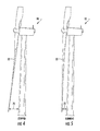
- the blades 22 are subjected to various forces and bending moments. As such, the blades 22 may deflect from a neutral, or non-deflected, position to a deflected position.
- the non-deflected blade clearance, distance 70 represents the distance between the rotor blades 22 and the tower 12 when the blades 22 are in a non-deflected position (i.e. when the wind turbine is stopped or not operating).
- forces and bending moments acting on the rotor blades 22 during operation may cause the blades 22 to deflect towards the tower 12, as shown in FIG. 5 , thereby reducing the overall blade clearance 70.
- aerodynamic loads increase, excessive forces and bending moments can cause one or more of the blades 22 to strike the tower 12 resulting in significant damage and downtime.
- the present subject matter is directed to a system for monitoring and controlling the blade deflection of the rotor blades 22 of the wind turbine 10 so as to prevent tower strikes.
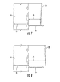
- a flow diagram of a blade clearance control scheme 100 that can be implemented by controller 36 is illustrated.
- the controller 36 is configured to monitor a loading condition of the wind turbine 10 over a predetermined time period.
- the predetermined time period may be any suitable time period, e.g. any number of seconds, minutes, hours, days, etc.
- the loading condition may be any suitable loading condition of the wind turbine 10.
- one or more of the sensors 48, 50, 52, 54, 56 are configured to measure the tower acceleration of the wind turbine tower 12.
- the controller 36 is configured to activate the blade clearance control scheme of the present disclosure.
- the controller 36 may also track a number of wind condition deviations of a certain amount or magnitude occurring during a predetermined time period. It should be understood that the predetermined time period for tracking the number of wind condition deviations may be equal to, greater than, or less than the predetermined time period for monitoring the loading conditions.
- a “wind condition deviation” may include any change or instability of a certain wind condition, such as for example, a wind direction deviation or instability or a significant change in wind speed that is representative of a wind gust, which may also be referred to herein as a "wind speed deviation.”
- the controller 36 is configured to activate the blade clearance control scheme of the present disclosure.
- the blade clearance control scheme may be activated when either or both the number of wind condition deviations or the loading condition exceed their respective thresholds.
- the controller 36 may determine the wind deviation threshold based on certain combinations of environmental conditions, normal turbine operation, and/or blade structural properties that can result in enough blade deflection to allow contact with the tower 12. For example, in particular embodiments, the controller 36 may determine the wind deviation threshold based on highly complex site topography, steep up-flow terrain angles, large hills or elevated terrain features upwind of the wind turbine 10, frequent periods of rapid and/or severe wind direction shifts, current wind conditions of the site, historical wind conditions recorded from the site, and/or gusty or turbulent wind conditions.
- wind conditions as used herein may include any suitable wind condition at or near the wind turbine 10, including but not limited to wind gusts, wind speed, wind direction, wind acceleration, wind turbulence, wind shear, wind veer, or wake conditions.
- the controller 36 may determine the loading threshold based on a variety of factors.
- the loading threshold may be determined as a function of an average loading condition of a rotor blade 22 over a certain time period and/or a standard deviation of a loading condition of a rotor blade 22 over a certain time period.
- the loading threshold may be a predetermined value set by the controller 36.
- the loading threshold may be fixed and/or updated according to one or more factors, such as environmental conditions, normal turbine operation, and/or normal blade structural properties (e.g. blade materials, size, age, etc.).
- the thresholds described herein may be set such that detection of an over-threshold condition indicates that a blade deflection of a certain magnitude is occurring or is more probable in the current detected conditions and may cause damage if not corrected.
- the blade clearance control scheme may be activated to reduce the likelihood of a tower strike.
- the controller 36 is configured to perform one or more corrective actions so as to reduce blade deflection and protect the wind turbine 10 from a blade tower strike.
- the corrective action may include altering a blade pitch angle (e.g. one or more standard pitch settings) of at least one of the rotor blades 22. More specifically, the controller 36 may alter a blade pitch of one or more of the rotor blades 22.
- this may be accomplished by controlling a pitch adjustment system 32.
- altering the blade pitch of a turbine blade 22 reduces blade deflection by decreasing aerodynamic loads and increasing out-of-plane stiffness.
- the selected pitch angle is configured to alter conditions of the wind turbine 10 that are the most likely to cause the rotor blades 22 to deflect, e.g. when wind speeds are approximately mid-level wind speeds such as 6 to 17 meters per second (m/s).
- the additional blade pitch offset provides operational blade angles that are slightly higher than standard or normal pitch settings present before the blade clearance control scheme is activated. Accordingly, the corresponding torque, power, loads, and/or deflection of the wind turbine 10 and/or the rotor blades 22 may be reduced.
- the controller 36 may be configured to perform one or more additional corrective actions preventatively, such as by making a one-time parameter change, in anticipation of operating conditions that may present an increased likelihood of a tower strike, as well as reactively in response to blade deflection of one or more of the rotor blades 22.
- the corrective action may allow a wind turbine 10 to be adaptable to varying operating conditions which may otherwise result in significant aerodynamic loading on the rotor blades 22. More specifically, the corrective action may include reducing standard operating limits for wind speed, de-rating the power output of the wind turbine, and/or reducing a torque of the wind turbine 10.
- the corrective action may include yawing the nacelle 16 to change the angle of the nacelle 16 relative to the direction 28 ( FIG. 1 ) of the wind.
- the yaw drive mechanism 66 is typically used to change the angle of the nacelle 16 so that the rotor blades 22 are properly angled with respect to the prevailing wind.
- controller 36 need not perform one of the corrective actions described above and may generally perform any corrective action designed to reduce blade deflection. Additionally, the controller 36 may be configured to perform multiple corrective actions simultaneously, which may include one or more of the corrective actions described above.
- the controller 36 can also continuously monitor the loading conditions and/or the wind condition deviations to ensure that the corrective action is effective in reducing deflection of the rotor blades 22.
- the controller 36 may be configured to revert back to standard pitch angle settings (or standard operating settings that existed before the corrective action) after a certain amount of time (e.g. as determined via timer 114).
- the controller 36 may revert back to standard operating settings after a power output of the wind turbine 10 remains below a predetermined threshold for a specified time period.
- the controller 36 is configured to revert back to standard operating conditions after the number of wind condition deviations and/or the loading condition of the wind turbine 10 remain below their respective thresholds for a specified time period.
- FIGS. 7 and 8 illustrate side, partial views of a wind turbine 10 during operation having a tower 12 with diameter 15 and a rotor blade 22 having a tower clearance 70. More specifically, FIG. 7 illustrates the tower clearance 70 of the rotor blade 22 without activating the blade clearance control scheme of the present disclosure, whereas FIG. 8 illustrates the tower clearance 70 of the rotor blade 22 in equivalent conditions as FIG. 7 with the blade clearance control scheme activated. As shown for comparison purposes only, the tower clearance 70 of FIG. 7 is less than the tower diameter 15, whereas the tower clearance 70 of FIG. 8 is greater than the tower diameter 15. Thus, the blade clearance control scheme decreases the likelihood of a blade tower strike by increasing the tower clearance 70.
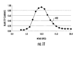
- FIGS. 9-11 various graphs illustrating further advantages of the blade clearance control scheme according to one embodiment of the present disclosure are shown. More specifically, FIG. 9 illustrates blade deflection versus wind speed, FIG. 10 illustrates power versus wind speed, and FIG. 11 illustrates the increase in the blade tip clearance versus wind speed as compared to standard operating settings.
- line 202 represents the blade deflection without activating the blade clearance control scheme
- line 204 represents the blade deflection with the blade clearance control scheme activated.
- the blade deflection is substantially reduced, especially for wind speeds of between about 6 m/s and about 17 m/s. Referring to FIG.
- line 302 represents the power (in kilowatts) produced by the wind turbine 10 without activating the blade clearance control scheme
- line 304 represents the power produced by the wind turbine 10 with the blade clearance control scheme activated.
- the power output is only marginally reduced when the control scheme is activated.
- the control scheme typically only causes a power loss of 11% or less, such as for example, between about 5% to about 7%.
- line 402 represents the increase in blade tip clearance as a function of wind speed as compared to standard operating settings.
- the blade clearance control scheme typically provides the most noticeable blade tip clearance improvement at mid-level wind speeds, e.g. from about 6 m/s and about 17 m/s.
Landscapes
- Engineering & Computer Science (AREA)
- Life Sciences & Earth Sciences (AREA)
- Sustainable Development (AREA)
- Sustainable Energy (AREA)
- Chemical & Material Sciences (AREA)
- Combustion & Propulsion (AREA)
- Mechanical Engineering (AREA)
- General Engineering & Computer Science (AREA)
- Physics & Mathematics (AREA)
- Fluid Mechanics (AREA)
- Wind Motors (AREA)
Applications Claiming Priority (1)
| Application Number | Priority Date | Filing Date | Title |
|---|---|---|---|
| US14/550,144 US9909563B2 (en) | 2014-11-21 | 2014-11-21 | System and method for monitoring and controlling wind turbine blade deflection |
Publications (2)
| Publication Number | Publication Date |
|---|---|
| EP3023635A1 true EP3023635A1 (fr) | 2016-05-25 |
| EP3023635B1 EP3023635B1 (fr) | 2021-03-03 |
Family
ID=54539960
Family Applications (1)
| Application Number | Title | Priority Date | Filing Date |
|---|---|---|---|
| EP15194067.3A Active EP3023635B1 (fr) | 2014-11-21 | 2015-11-11 | Système et procédé de surveillance et de contrôle de déflexion de pale d'éolienne |
Country Status (4)
| Country | Link |
|---|---|
| US (1) | US9909563B2 (fr) |
| EP (1) | EP3023635B1 (fr) |
| DK (1) | DK3023635T3 (fr) |
| ES (1) | ES2873234T3 (fr) |
Cited By (6)
| Publication number | Priority date | Publication date | Assignee | Title |
|---|---|---|---|---|
| CN108953073A (zh) * | 2018-08-07 | 2018-12-07 | 绵阳鼎飞益电子科技有限公司 | 风力发电机运行状态监测方法 |
| CN110621959A (zh) * | 2016-12-16 | 2019-12-27 | 英内杰克斯有限公司 | 用于监测风力涡轮机叶片偏转的系统和方法 |
| CN111720271A (zh) * | 2020-06-30 | 2020-09-29 | 国电联合动力技术有限公司 | 一种风电机组载荷在线预测的智能方法及风电机组 |
| CN112283047A (zh) * | 2020-09-10 | 2021-01-29 | 中车株洲电力机车研究所有限公司 | 一种基于风电机组净空监测的载荷监控方法及系统 |
| CN112709669A (zh) * | 2019-10-25 | 2021-04-27 | 北京金风科创风电设备有限公司 | 基于风力发电机组的塔架净空的变桨控制方法和设备 |
| EP3812577A1 (fr) * | 2019-10-22 | 2021-04-28 | General Electric Company | Système et procédé pour atténuer les charges agissant sur une pale de rotor d'une éolienne |
Families Citing this family (15)
| Publication number | Priority date | Publication date | Assignee | Title |
|---|---|---|---|---|
| CN109716077B (zh) * | 2016-06-27 | 2021-04-27 | 比勒陀利亚大学 | 使用叶尖定时(btt)监测涡轮机转子叶片的方法和系统 |
| US10570883B2 (en) * | 2017-12-22 | 2020-02-25 | General Electric Company | System and method for protecting wind turbines during wind gusts |
| DE102018112825A1 (de) * | 2018-05-29 | 2019-12-05 | fos4X GmbH | Sensoranordnung für eine Windkraftanlage |
| DE102018113531A1 (de) * | 2018-06-06 | 2019-12-12 | Wobben Properties Gmbh | Verfahren zum Betreiben einer Windenergieanlage sowie Einrichtung zum Steuern und/oder Regeln einer Windenergieanlage und Windenergieanlage mit einem Rotor und einem über den Rotor angetriebenen Generator |
| US10823146B2 (en) * | 2018-06-14 | 2020-11-03 | General Electric Company | System and method for controlling a wind turbine to minimize rotor blade damage |
| EP3741990A1 (fr) * | 2019-05-20 | 2020-11-25 | Siemens Gamesa Renewable Energy A/S | Dispositif et procédé pour commander une éolienne sur la base d'un élément de changement |
| CN112283030B (zh) * | 2019-07-24 | 2022-09-06 | 新疆金风科技股份有限公司 | 风力发电机组的控制方法及设备 |
| CN110886679B (zh) * | 2019-11-20 | 2020-11-06 | 明阳智慧能源集团股份公司 | 一种用于风力发电机组主动控制叶片净空的方法 |
| CN112983750B (zh) * | 2019-12-13 | 2022-07-19 | 中车株洲电力机车研究所有限公司 | 一种风电机组叶片安装错位诊断方法及装置 |
| CN113090458B (zh) * | 2019-12-23 | 2022-04-15 | 江苏金风科技有限公司 | 叶片控制方法和系统、控制器及计算机可读存储介质 |
| CN113090471B (zh) * | 2019-12-23 | 2022-10-14 | 新疆金风科技股份有限公司 | 风力发电机组的塔架净空音频监测系统、方法及装置 |
| CN113847211B (zh) * | 2020-06-28 | 2023-04-11 | 北京金风科创风电设备有限公司 | 风力发电机组的净空监测系统、方法及控制器 |
| CN112610412B (zh) * | 2020-12-23 | 2022-03-01 | 山东中车风电有限公司 | 一种基于载荷检测的风电机组叶片净空控制方法 |
| CN113482862B (zh) * | 2021-07-07 | 2022-10-18 | 陕西中科启航科技有限公司 | 一种风电机组运行状态监控方法及系统 |
| CN115342033A (zh) * | 2022-07-13 | 2022-11-15 | 中国海洋大学 | 基于叶片净空和风轮转速的尾流检测方法及系统 |
Citations (5)
| Publication number | Priority date | Publication date | Assignee | Title |
|---|---|---|---|---|
| US20070018457A1 (en) * | 2005-07-22 | 2007-01-25 | Gamesa Eolica, S.A. | Method of operating a wind turbine |
| EP2249030A2 (fr) * | 2009-05-07 | 2010-11-10 | Vestas Wind Systems A/S | Éolienne |
| EP2690285A2 (fr) * | 2012-07-26 | 2014-01-29 | General Electric Company | Contrôle du jeu entre les pales et le mât d'une éolienne |
| US20140203563A1 (en) * | 2011-06-30 | 2014-07-24 | Vestas Wind Systems A/S | System and method for controlling power output from a wind turbine or wind power plant |
| US20140294584A1 (en) * | 2013-03-27 | 2014-10-02 | Alstom Renovables Espana, S.L. | Method of operating a wind turbine |
Family Cites Families (17)
| Publication number | Priority date | Publication date | Assignee | Title |
|---|---|---|---|---|
| CN101517229B (zh) * | 2006-09-14 | 2012-05-23 | 维斯塔斯风力系统有限公司 | 控制连接到市电网的风力涡轮机的方法、风力涡轮机与风电厂 |
| US20100226772A1 (en) | 2009-02-25 | 2010-09-09 | Kenneth James Deering | Blade control system |
| EP2239462A1 (fr) | 2009-04-07 | 2010-10-13 | Siemens Aktiengesellschaft | Procédé et agencement pour mesurer la déflection d'une pale de turbine d'éolienne |
| US8441138B2 (en) * | 2009-05-07 | 2013-05-14 | Vestas Wind Systems A/S | Wind turbine |
| DK201070274A (en) * | 2009-10-08 | 2011-04-09 | Vestas Wind Sys As | Control method for a wind turbine |
| GB2479923A (en) | 2010-04-29 | 2011-11-02 | Vestas Wind Sys As | A method and system for detecting angular deflection in a wind turbine blade, or component, or between wind turbine components |
| GB2482661A (en) | 2010-07-26 | 2012-02-15 | Vestas Wind Sys As | Upwind wind turbine with tower-mounted air pressure sensors |
| GB2485340A (en) | 2010-11-02 | 2012-05-16 | Vestas Wind Sys As | A wind turbine comprising rotor and tower bending sensors |
| GB2485595A (en) | 2010-11-19 | 2012-05-23 | Vestas Wind Sys As | Wind turbine |
| WO2012139592A2 (fr) | 2011-04-13 | 2012-10-18 | Vestas Wind Systems A/S | Eolienne comprenant un système de capteurs optiques |
| DK2726735T3 (da) | 2011-06-27 | 2017-01-02 | Lm Wp Patent Holding As | Fremgangsmåde til styring af et vindenergianlæg |
| US20130045098A1 (en) | 2011-08-18 | 2013-02-21 | Clipper Windpower, Llc | Cyclic Pitch Control System for Wind Turbine Blades |
| KR20130046858A (ko) | 2011-10-28 | 2013-05-08 | 엘에스전선 주식회사 | 풍력 발전기 블레이드 감시 시스템 및 이를 이용한 감시 방법 |
| US9683551B2 (en) * | 2011-12-29 | 2017-06-20 | Vestas Wind Systems A/S | Optimization of power production in a wind turbine at below rated power |
| CN103225587B (zh) | 2012-01-31 | 2015-07-29 | 北京能高自动化技术股份有限公司 | 一种下风向风力发电机组 |
| CN104411967B (zh) | 2012-06-06 | 2017-08-15 | 维斯塔斯风力系统集团公司 | 带有载荷控制器的风力涡轮机 |
| WO2014078770A1 (fr) | 2012-11-19 | 2014-05-22 | Elwha Llc | Atténuation de génération de bruit de pale de turbine éolienne |
-
2014
- 2014-11-21 US US14/550,144 patent/US9909563B2/en active Active
-
2015
- 2015-11-11 EP EP15194067.3A patent/EP3023635B1/fr active Active
- 2015-11-11 DK DK15194067.3T patent/DK3023635T3/da active
- 2015-11-11 ES ES15194067T patent/ES2873234T3/es active Active
Patent Citations (5)
| Publication number | Priority date | Publication date | Assignee | Title |
|---|---|---|---|---|
| US20070018457A1 (en) * | 2005-07-22 | 2007-01-25 | Gamesa Eolica, S.A. | Method of operating a wind turbine |
| EP2249030A2 (fr) * | 2009-05-07 | 2010-11-10 | Vestas Wind Systems A/S | Éolienne |
| US20140203563A1 (en) * | 2011-06-30 | 2014-07-24 | Vestas Wind Systems A/S | System and method for controlling power output from a wind turbine or wind power plant |
| EP2690285A2 (fr) * | 2012-07-26 | 2014-01-29 | General Electric Company | Contrôle du jeu entre les pales et le mât d'une éolienne |
| US20140294584A1 (en) * | 2013-03-27 | 2014-10-02 | Alstom Renovables Espana, S.L. | Method of operating a wind turbine |
Non-Patent Citations (1)
| Title |
|---|
| Y. DENG ET AL: "Blade tip deflection calculations and safety analysis of wind turbine", RENEWABLE POWER GENERATION CONFERENCE (RPG 2013), 2ND IET, 9-11 SEPT. 2013, 11 September 2013 (2013-09-11), Beijing, pages 1 - 5, XP055261749, Retrieved from the Internet <URL:http://ieeexplore.ieee.org/ielx7/6712179/6718532/06718752.pdf?tp=&arnumber=6718752&isnumber=6718532> [retrieved on 20160331], DOI: 10.1049/cp.2013.1841 * |
Cited By (8)
| Publication number | Priority date | Publication date | Assignee | Title |
|---|---|---|---|---|
| CN110621959A (zh) * | 2016-12-16 | 2019-12-27 | 英内杰克斯有限公司 | 用于监测风力涡轮机叶片偏转的系统和方法 |
| US10774814B2 (en) | 2016-12-16 | 2020-09-15 | Innergex Inc. | System and method for monitoring blade deflection of wind turbines |
| CN108953073A (zh) * | 2018-08-07 | 2018-12-07 | 绵阳鼎飞益电子科技有限公司 | 风力发电机运行状态监测方法 |
| EP3812577A1 (fr) * | 2019-10-22 | 2021-04-28 | General Electric Company | Système et procédé pour atténuer les charges agissant sur une pale de rotor d'une éolienne |
| CN112709669A (zh) * | 2019-10-25 | 2021-04-27 | 北京金风科创风电设备有限公司 | 基于风力发电机组的塔架净空的变桨控制方法和设备 |
| CN111720271A (zh) * | 2020-06-30 | 2020-09-29 | 国电联合动力技术有限公司 | 一种风电机组载荷在线预测的智能方法及风电机组 |
| CN112283047A (zh) * | 2020-09-10 | 2021-01-29 | 中车株洲电力机车研究所有限公司 | 一种基于风电机组净空监测的载荷监控方法及系统 |
| CN112283047B (zh) * | 2020-09-10 | 2022-07-12 | 中车株洲电力机车研究所有限公司 | 一种基于风电机组净空监测的载荷监控方法及系统 |
Also Published As
| Publication number | Publication date |
|---|---|
| US20160146189A1 (en) | 2016-05-26 |
| ES2873234T3 (es) | 2021-11-03 |
| US9909563B2 (en) | 2018-03-06 |
| DK3023635T3 (da) | 2021-06-07 |
| EP3023635B1 (fr) | 2021-03-03 |
Similar Documents
| Publication | Publication Date | Title |
|---|---|---|
| EP3023635B1 (fr) | Système et procédé de surveillance et de contrôle de déflexion de pale d'éolienne | |
| US7573149B2 (en) | System and method for controlling a wind power plant | |
| US7772713B2 (en) | Method and system for controlling a wind turbine | |
| US9140239B2 (en) | Wind power plant controller for avoiding common cause shutdown | |
| US9551321B2 (en) | System and method for controlling a wind turbine | |
| EP2910777B1 (fr) | Vitesse dynamique de vent minimum de démarrage pour éoliennes | |
| US10830208B2 (en) | System and method for mitigating blade run-away loads in the event of a pitch system failure | |
| EP3470670B1 (fr) | Système et procédé de fonctionnement d'éoliennes permettant d'éviter le décrochage lors d'un fonctionnement à puissance réduite | |
| EP3581795B1 (fr) | Système et procédé de commande d'éolienne pour minimiser les dommages de pales de rotor | |
| EP3599375A1 (fr) | Système et procédé pour protéger des éoliennes pendant un changement de direction de vents extrêmes | |
| EP3643914B1 (fr) | Système et procédé pour protéger des éoliennes contre les charges extrêmes et de fatigue | |
| EP3597904B1 (fr) | Système et procédé de réduction des charges d'éolienne par orientation de la nacelle dans une position prédéterminée basée sur un déséquilibre de rotor | |
| US20230011028A1 (en) | System and method for monitoring rotor blade health of a wind turbine | |
| US11608811B2 (en) | System and method for mitigating loads acting on a rotor blade of a wind turbine | |
| US11913429B2 (en) | System and method for slip detection and surface health monitoring in a slip coupling of a rotary shaft | |
| US20240133360A1 (en) | Protection of wind turbine components during yawing | |
| EP4361434A1 (fr) | Protection de composants d'éolienne pendant le lacet | |
| US11754039B1 (en) | Load dependent autonomous yaw control for a wind turbine | |
| JP2023165630A (ja) | 風力タービン制御 |
Legal Events
| Date | Code | Title | Description |
|---|---|---|---|
| AK | Designated contracting states |
Kind code of ref document: A1 Designated state(s): AL AT BE BG CH CY CZ DE DK EE ES FI FR GB GR HR HU IE IS IT LI LT LU LV MC MK MT NL NO PL PT RO RS SE SI SK SM TR |
|
| AX | Request for extension of the european patent |
Extension state: BA ME |
|
| PUAI | Public reference made under article 153(3) epc to a published international application that has entered the european phase |
Free format text: ORIGINAL CODE: 0009012 |
|
| STAA | Information on the status of an ep patent application or granted ep patent |
Free format text: STATUS: REQUEST FOR EXAMINATION WAS MADE |
|
| 17P | Request for examination filed |
Effective date: 20161125 |
|
| RBV | Designated contracting states (corrected) |
Designated state(s): AL AT BE BG CH CY CZ DE DK EE ES FI FR GB GR HR HU IE IS IT LI LT LU LV MC MK MT NL NO PL PT RO RS SE SI SK SM TR |
|
| STAA | Information on the status of an ep patent application or granted ep patent |
Free format text: STATUS: EXAMINATION IS IN PROGRESS |
|
| 17Q | First examination report despatched |
Effective date: 20181219 |
|
| GRAP | Despatch of communication of intention to grant a patent |
Free format text: ORIGINAL CODE: EPIDOSNIGR1 |
|
| STAA | Information on the status of an ep patent application or granted ep patent |
Free format text: STATUS: GRANT OF PATENT IS INTENDED |
|
| INTG | Intention to grant announced |
Effective date: 20200928 |
|
| GRAS | Grant fee paid |
Free format text: ORIGINAL CODE: EPIDOSNIGR3 |
|
| STAA | Information on the status of an ep patent application or granted ep patent |
Free format text: STATUS: GRANT OF PATENT IS INTENDED |
|
| GRAA | (expected) grant |
Free format text: ORIGINAL CODE: 0009210 |
|
| STAA | Information on the status of an ep patent application or granted ep patent |
Free format text: STATUS: THE PATENT HAS BEEN GRANTED |
|
| AK | Designated contracting states |
Kind code of ref document: B1 Designated state(s): AL AT BE BG CH CY CZ DE DK EE ES FI FR GB GR HR HU IE IS IT LI LT LU LV MC MK MT NL NO PL PT RO RS SE SI SK SM TR |
|
| REG | Reference to a national code |
Ref country code: GB Ref legal event code: FG4D |
|
| REG | Reference to a national code |
Ref country code: AT Ref legal event code: REF Ref document number: 1367474 Country of ref document: AT Kind code of ref document: T Effective date: 20210315 Ref country code: CH Ref legal event code: EP |
|
| REG | Reference to a national code |
Ref country code: DE Ref legal event code: R096 Ref document number: 602015066266 Country of ref document: DE |
|
| REG | Reference to a national code |
Ref country code: IE Ref legal event code: FG4D |
|
| REG | Reference to a national code |
Ref country code: DK Ref legal event code: T3 Effective date: 20210601 |
|
| REG | Reference to a national code |
Ref country code: LT Ref legal event code: MG9D |
|
| PG25 | Lapsed in a contracting state [announced via postgrant information from national office to epo] |
Ref country code: LT Free format text: LAPSE BECAUSE OF FAILURE TO SUBMIT A TRANSLATION OF THE DESCRIPTION OR TO PAY THE FEE WITHIN THE PRESCRIBED TIME-LIMIT Effective date: 20210303 Ref country code: HR Free format text: LAPSE BECAUSE OF FAILURE TO SUBMIT A TRANSLATION OF THE DESCRIPTION OR TO PAY THE FEE WITHIN THE PRESCRIBED TIME-LIMIT Effective date: 20210303 Ref country code: FI Free format text: LAPSE BECAUSE OF FAILURE TO SUBMIT A TRANSLATION OF THE DESCRIPTION OR TO PAY THE FEE WITHIN THE PRESCRIBED TIME-LIMIT Effective date: 20210303 Ref country code: GR Free format text: LAPSE BECAUSE OF FAILURE TO SUBMIT A TRANSLATION OF THE DESCRIPTION OR TO PAY THE FEE WITHIN THE PRESCRIBED TIME-LIMIT Effective date: 20210604 Ref country code: NO Free format text: LAPSE BECAUSE OF FAILURE TO SUBMIT A TRANSLATION OF THE DESCRIPTION OR TO PAY THE FEE WITHIN THE PRESCRIBED TIME-LIMIT Effective date: 20210603 Ref country code: BG Free format text: LAPSE BECAUSE OF FAILURE TO SUBMIT A TRANSLATION OF THE DESCRIPTION OR TO PAY THE FEE WITHIN THE PRESCRIBED TIME-LIMIT Effective date: 20210603 |
|
| REG | Reference to a national code |
Ref country code: NL Ref legal event code: MP Effective date: 20210303 |
|
| REG | Reference to a national code |
Ref country code: AT Ref legal event code: MK05 Ref document number: 1367474 Country of ref document: AT Kind code of ref document: T Effective date: 20210303 |
|
| PG25 | Lapsed in a contracting state [announced via postgrant information from national office to epo] |
Ref country code: PL Free format text: LAPSE BECAUSE OF FAILURE TO SUBMIT A TRANSLATION OF THE DESCRIPTION OR TO PAY THE FEE WITHIN THE PRESCRIBED TIME-LIMIT Effective date: 20210303 Ref country code: RS Free format text: LAPSE BECAUSE OF FAILURE TO SUBMIT A TRANSLATION OF THE DESCRIPTION OR TO PAY THE FEE WITHIN THE PRESCRIBED TIME-LIMIT Effective date: 20210303 Ref country code: LV Free format text: LAPSE BECAUSE OF FAILURE TO SUBMIT A TRANSLATION OF THE DESCRIPTION OR TO PAY THE FEE WITHIN THE PRESCRIBED TIME-LIMIT Effective date: 20210303 Ref country code: SE Free format text: LAPSE BECAUSE OF FAILURE TO SUBMIT A TRANSLATION OF THE DESCRIPTION OR TO PAY THE FEE WITHIN THE PRESCRIBED TIME-LIMIT Effective date: 20210303 |
|
| PG25 | Lapsed in a contracting state [announced via postgrant information from national office to epo] |
Ref country code: NL Free format text: LAPSE BECAUSE OF FAILURE TO SUBMIT A TRANSLATION OF THE DESCRIPTION OR TO PAY THE FEE WITHIN THE PRESCRIBED TIME-LIMIT Effective date: 20210303 |
|
| PG25 | Lapsed in a contracting state [announced via postgrant information from national office to epo] |
Ref country code: CZ Free format text: LAPSE BECAUSE OF FAILURE TO SUBMIT A TRANSLATION OF THE DESCRIPTION OR TO PAY THE FEE WITHIN THE PRESCRIBED TIME-LIMIT Effective date: 20210303 Ref country code: EE Free format text: LAPSE BECAUSE OF FAILURE TO SUBMIT A TRANSLATION OF THE DESCRIPTION OR TO PAY THE FEE WITHIN THE PRESCRIBED TIME-LIMIT Effective date: 20210303 Ref country code: SM Free format text: LAPSE BECAUSE OF FAILURE TO SUBMIT A TRANSLATION OF THE DESCRIPTION OR TO PAY THE FEE WITHIN THE PRESCRIBED TIME-LIMIT Effective date: 20210303 Ref country code: AT Free format text: LAPSE BECAUSE OF FAILURE TO SUBMIT A TRANSLATION OF THE DESCRIPTION OR TO PAY THE FEE WITHIN THE PRESCRIBED TIME-LIMIT Effective date: 20210303 |
|
| REG | Reference to a national code |
Ref country code: ES Ref legal event code: FG2A Ref document number: 2873234 Country of ref document: ES Kind code of ref document: T3 Effective date: 20211103 |
|
| PG25 | Lapsed in a contracting state [announced via postgrant information from national office to epo] |
Ref country code: IS Free format text: LAPSE BECAUSE OF FAILURE TO SUBMIT A TRANSLATION OF THE DESCRIPTION OR TO PAY THE FEE WITHIN THE PRESCRIBED TIME-LIMIT Effective date: 20210703 Ref country code: SK Free format text: LAPSE BECAUSE OF FAILURE TO SUBMIT A TRANSLATION OF THE DESCRIPTION OR TO PAY THE FEE WITHIN THE PRESCRIBED TIME-LIMIT Effective date: 20210303 Ref country code: RO Free format text: LAPSE BECAUSE OF FAILURE TO SUBMIT A TRANSLATION OF THE DESCRIPTION OR TO PAY THE FEE WITHIN THE PRESCRIBED TIME-LIMIT Effective date: 20210303 Ref country code: PT Free format text: LAPSE BECAUSE OF FAILURE TO SUBMIT A TRANSLATION OF THE DESCRIPTION OR TO PAY THE FEE WITHIN THE PRESCRIBED TIME-LIMIT Effective date: 20210705 |
|
| REG | Reference to a national code |
Ref country code: DE Ref legal event code: R097 Ref document number: 602015066266 Country of ref document: DE |
|
| PLBE | No opposition filed within time limit |
Free format text: ORIGINAL CODE: 0009261 |
|
| STAA | Information on the status of an ep patent application or granted ep patent |
Free format text: STATUS: NO OPPOSITION FILED WITHIN TIME LIMIT |
|
| PG25 | Lapsed in a contracting state [announced via postgrant information from national office to epo] |
Ref country code: AL Free format text: LAPSE BECAUSE OF FAILURE TO SUBMIT A TRANSLATION OF THE DESCRIPTION OR TO PAY THE FEE WITHIN THE PRESCRIBED TIME-LIMIT Effective date: 20210303 |
|
| 26N | No opposition filed |
Effective date: 20211206 |
|
| PG25 | Lapsed in a contracting state [announced via postgrant information from national office to epo] |
Ref country code: SI Free format text: LAPSE BECAUSE OF FAILURE TO SUBMIT A TRANSLATION OF THE DESCRIPTION OR TO PAY THE FEE WITHIN THE PRESCRIBED TIME-LIMIT Effective date: 20210303 |
|
| PG25 | Lapsed in a contracting state [announced via postgrant information from national office to epo] |
Ref country code: IT Free format text: LAPSE BECAUSE OF FAILURE TO SUBMIT A TRANSLATION OF THE DESCRIPTION OR TO PAY THE FEE WITHIN THE PRESCRIBED TIME-LIMIT Effective date: 20210303 |
|
| PG25 | Lapsed in a contracting state [announced via postgrant information from national office to epo] |
Ref country code: IS Free format text: LAPSE BECAUSE OF FAILURE TO SUBMIT A TRANSLATION OF THE DESCRIPTION OR TO PAY THE FEE WITHIN THE PRESCRIBED TIME-LIMIT Effective date: 20210703 |
|
| PG25 | Lapsed in a contracting state [announced via postgrant information from national office to epo] |
Ref country code: MC Free format text: LAPSE BECAUSE OF FAILURE TO SUBMIT A TRANSLATION OF THE DESCRIPTION OR TO PAY THE FEE WITHIN THE PRESCRIBED TIME-LIMIT Effective date: 20210303 |
|
| REG | Reference to a national code |
Ref country code: CH Ref legal event code: PL |
|
| GBPC | Gb: european patent ceased through non-payment of renewal fee |
Effective date: 20211111 |
|
| PG25 | Lapsed in a contracting state [announced via postgrant information from national office to epo] |
Ref country code: LU Free format text: LAPSE BECAUSE OF NON-PAYMENT OF DUE FEES Effective date: 20211111 Ref country code: BE Free format text: LAPSE BECAUSE OF NON-PAYMENT OF DUE FEES Effective date: 20211130 |
|
| REG | Reference to a national code |
Ref country code: BE Ref legal event code: MM Effective date: 20211130 |
|
| PG25 | Lapsed in a contracting state [announced via postgrant information from national office to epo] |
Ref country code: IE Free format text: LAPSE BECAUSE OF NON-PAYMENT OF DUE FEES Effective date: 20211111 Ref country code: GB Free format text: LAPSE BECAUSE OF NON-PAYMENT OF DUE FEES Effective date: 20211111 |
|
| PG25 | Lapsed in a contracting state [announced via postgrant information from national office to epo] |
Ref country code: FR Free format text: LAPSE BECAUSE OF NON-PAYMENT OF DUE FEES Effective date: 20211130 |
|
| PG25 | Lapsed in a contracting state [announced via postgrant information from national office to epo] |
Ref country code: HU Free format text: LAPSE BECAUSE OF FAILURE TO SUBMIT A TRANSLATION OF THE DESCRIPTION OR TO PAY THE FEE WITHIN THE PRESCRIBED TIME-LIMIT; INVALID AB INITIO Effective date: 20151111 |
|
| PG25 | Lapsed in a contracting state [announced via postgrant information from national office to epo] |
Ref country code: CY Free format text: LAPSE BECAUSE OF FAILURE TO SUBMIT A TRANSLATION OF THE DESCRIPTION OR TO PAY THE FEE WITHIN THE PRESCRIBED TIME-LIMIT Effective date: 20210303 |
|
| P01 | Opt-out of the competence of the unified patent court (upc) registered |
Effective date: 20230530 |
|
| PG25 | Lapsed in a contracting state [announced via postgrant information from national office to epo] |
Ref country code: LI Free format text: LAPSE BECAUSE OF NON-PAYMENT OF DUE FEES Effective date: 20220630 Ref country code: CH Free format text: LAPSE BECAUSE OF NON-PAYMENT OF DUE FEES Effective date: 20220630 |
|
| REG | Reference to a national code |
Representative=s name: ZIMMERMANN & PARTNER PATENTANWAELTE MBB, DE Ref country code: DE Ref legal event code: R082 Ref document number: 602015066266 Country of ref document: DE Ref country code: DE Ref legal event code: R081 Ref document number: 602015066266 Country of ref document: DE Owner name: GENERAL ELECTRIC RENOVABLES ESPANA, S.L., ES Free format text: FORMER OWNER: GENERAL ELECTRIC COMPANY, SCHENECTADY, NY, US |
|
| PGFP | Annual fee paid to national office [announced via postgrant information from national office to epo] |
Ref country code: ES Payment date: 20231201 Year of fee payment: 9 |
|
| PGFP | Annual fee paid to national office [announced via postgrant information from national office to epo] |
Ref country code: DK Payment date: 20231019 Year of fee payment: 9 Ref country code: DE Payment date: 20231019 Year of fee payment: 9 |
|
| REG | Reference to a national code |
Ref country code: DE Ref legal event code: R082 Ref document number: 602015066266 Country of ref document: DE Representative=s name: ZIMMERMANN & PARTNER PATENTANWAELTE MBB, DE |
|
| PG25 | Lapsed in a contracting state [announced via postgrant information from national office to epo] |
Ref country code: MK Free format text: LAPSE BECAUSE OF FAILURE TO SUBMIT A TRANSLATION OF THE DESCRIPTION OR TO PAY THE FEE WITHIN THE PRESCRIBED TIME-LIMIT Effective date: 20210303 |