EP3023557A1 - Profile for a ventilated roof structure - Google Patents
Profile for a ventilated roof structure Download PDFInfo
- Publication number
- EP3023557A1 EP3023557A1 EP15195329.6A EP15195329A EP3023557A1 EP 3023557 A1 EP3023557 A1 EP 3023557A1 EP 15195329 A EP15195329 A EP 15195329A EP 3023557 A1 EP3023557 A1 EP 3023557A1
- Authority
- EP
- European Patent Office
- Prior art keywords
- profile
- support
- support portion
- insulating layer
- recesses
- Prior art date
- Legal status (The legal status is an assumption and is not a legal conclusion. Google has not performed a legal analysis and makes no representation as to the accuracy of the status listed.)
- Withdrawn
Links
Images


Classifications
-
- E—FIXED CONSTRUCTIONS
- E04—BUILDING
- E04D—ROOF COVERINGS; SKY-LIGHTS; GUTTERS; ROOF-WORKING TOOLS
- E04D13/00—Special arrangements or devices in connection with roof coverings; Protection against birds; Roof drainage; Sky-lights
- E04D13/17—Ventilation of roof coverings not otherwise provided for
-
- E—FIXED CONSTRUCTIONS
- E04—BUILDING
- E04D—ROOF COVERINGS; SKY-LIGHTS; GUTTERS; ROOF-WORKING TOOLS
- E04D12/00—Non-structural supports for roofing materials, e.g. battens, boards
- E04D12/004—Battens
-
- E—FIXED CONSTRUCTIONS
- E04—BUILDING
- E04D—ROOF COVERINGS; SKY-LIGHTS; GUTTERS; ROOF-WORKING TOOLS
- E04D13/00—Special arrangements or devices in connection with roof coverings; Protection against birds; Roof drainage; Sky-lights
- E04D13/17—Ventilation of roof coverings not otherwise provided for
- E04D13/172—Roof insulating material with provisions for or being arranged for permitting ventilation of the roof covering
Definitions
- the invention relates to a profile for a ventilated roof construction for arrangement between an insulating layer and a roof covering thereon, wherein the profile has two support portions for placing the profile on the insulating layer and a support portion, wherein the support portion is arranged spaced from the insulating layer and on the support portion the roof covering can be supported if the profile is intended to be arranged on the insulating layer, wherein the support section is connected in each case along longitudinal edges opposite one another via a support section with the support sections, so that the two support sections are each connected to the support section via a support section, wherein In each of the two support portions recesses are arranged to allow ventilation of the roof covering, and wherein at least some recesses at least one of the support portion in the direction of the Stü Have tzabites extending side edge.
- Profiles for ventilated roof structures are already known from practice. These profiles are arranged on the insulating layer and form a support for the roofing. In this way, the roof covering can be arranged spaced from the insulating layer, to allow ventilation of the roof covering.
- the distance between the roofing and the insulating layer serves, inter alia, to safely drain any rainwater entering through the roofing or condensation water accumulating on a lower side of the roofing and to dissipate moisture between the roofing and the insulating layer.
- the profiles are arranged with the support portions on the insulating layer, so that the support portion of the profile for supporting the roof covering is arranged spaced from the insulating layer.
- the profiles can be connected in advance with the insulating layer and then fixed with the insulating layer on the roof structure.
- screws can be used, which can be determined by the profiles and the respectively associated region of the insulating layer in a roof structure on which the insulating layer is placed.
- individual roof tiles or roof tiles or the like, which form the roofing, on the support sections the profiles are placed and fixed for example by wire clips on the profiles.
- the profiles are made in practice from a sheet metal or metal strip, which is deformed by punching and roll forming or multiple folding to a profile with support sections, with support sections and with a support section.
- a plurality of recesses are regularly arranged to allow for a ventilation of the roof construction and on the other to drain the condensed between the insulation layer and the roof covering liquid through the recesses in the profile.
- the support sections In order to allow the most efficient possible ventilation, the support sections must have as many or as large as possible recesses.
- the profile and in particular the support sections must nevertheless be designed to be stable in order to be able to bear the weight of the roof covering as well as the weight of persons standing on the profile during installation of the roof covering.
- the profiles known from practice are usually made of a sufficiently thick sheet metal or metal strip and have a number of recesses rounded off towards the support section.
- the rounded to the support portion shape of the recesses leads to the example made by a wire clip connection of an element of the roof covering with the profile is set as possible in a central region of a recess in which the distance of the recess to the overlying support section small is.
- Laterally spaced fixing means such as a wire clip or a manually made wire loop could slip towards the center and loosen.
- the cost of materials for the profiles and the assembly costs for fixing the roof covering on these profiles are significant.
- Another object of the invention is to provide a ventilated roof structure having an insulating layer and a roofing and a profile therebetween, and can be fixed to a roof structure, wherein the ventilated roof construction is easy to assemble and has a high stability, and also has a reduced corrosion of the profiles and a reduced penetration of liquid into the insulating layer.
- the object of the present invention is achieved in that in a rectilinear section of the side edge, a stabilizing strip is formed, which is angled aligned to a arranged on the side edge portion of the support portion.
- a stabilizing strip is formed on the side edge, which is angled aligned to a arranged on the side edge portion of the support portion.
- the profile can be additionally stabilized, so that the profile can bear the weight of a person during the assembly of the profile and the weight of the roof covering.
- the stabilization strip reduces the risk of a cut injury on the side edge of the recess, and furthermore the profile can be produced in a simple manner without increasing the production costs by additional stabilization measures. Due to the rectilinear side edge, the recess has a smaller rounding, so that a larger area towards the support portion has an at least approximately constant width and there is thereby facilitated a simple and reliable attachment of the roof covering.
- the profile may additionally be provided with a protective coating or with a coating.
- a coating with zinc, with a zinc-aluminum alloy, with an aluminum-zinc alloy or zinc-magnesium alloy is useful.
- the profile can also be made of a different material such as plastic.
- the stabilization strip projects at an angle from an area of the support section adjoining the rectilinear section of the side edge into an interior space of the profile formed by the support section and the support sections.
- the recesses have a top edge adjacent to the side edge and facing the support section, with a side edge extending from the support section toward the support section, wherein a stabilization strip is formed in a rectilinear section of the top edge, which angled toward one aligned at the top edge of the support portion is aligned.
- the stabilizing strip on the upper edge facing the support section allows the profile to be additionally stabilized. Due to the inventive design of the upper edge of the distance between the support portion and between the longitudinal edge of the support portion and the upper edge over a longer portion of the profile is constant away, so that a compound of the roof covering with the profile, for example by wire clips at each point along the straight line Upper edges is reliably possible and does not shift laterally or loosens over time.
- At least some recesses on the support section have two side edges extending from the support section towards the support section, wherein in each case a stabilizing strip is formed in a rectilinear section of the two side edges, which is angled toward one of the corresponding Side edge associated with the area of the support section is aligned.
- the stabilizing strips on the side edges can be configured in a matching manner and protrude, for example, a few millimeters from the support section into an interior space of the profile formed by the support sections, the support section and the support sections.
- at least some recesses in the support sections have a lower edge facing away from the support section and adjacent to the side edge, wherein the lower edge has no angled aligned stabilizing strips to facilitate a drainage of liquid on the insulating layer through the recesses.
- At least some recesses which are arranged in the support sections have a triangular shape and that a triangular side edge of the triangular recess facing the support section is aligned parallel to the longitudinal edge of the support section.
- An aligned parallel to the longitudinal edge triangle side edge allows a connection of the roof covering with the profile optionally on one of the numerous longer portions of the above-running triangle side edges of the profile.
- the connection of the roof covering with the profile does not change due to the same distance between the triangle side edge and the longitudinal edge or the top of the support portion even with a shift of individual elements of the roof covering or individual fasteners along the profile and allows a consistently reliable determination of the roof covering on the Profile.
- the stabilization strip formed on the triangle side edge enables additional stabilization of the profile.
- the weight of a person in the assembly of the roof structure and the weight of the roof covering including a conventional snow load without any deformation of the profile can be absorbed and removed. Due to the shape of the recesses and the formation of rectilinear side edges with stabilizing strips and the risk of cutting injury of persons involved in the assembly of the roof construction is reduced.
- At least some recesses which are arranged in the support sections have a trapezoidal shape and that a trapezoid side edge of the trapezoidal recess facing the support section is parallel is aligned with the longitudinal edge of the support portion.
- the trapezoidal configuration of the recesses makes it possible, on the one hand, for the spacing of the trapezoid side edge to the longitudinal edge of the support section to remain constant, and for, on the other hand, the profile is additionally stabilized by the stabilization strip formed on the trapezoid side edge.
- a lower trapezoidal edge which is arranged according to the invention on the support sections and has no stabilizing strip, allows the fluid condensed between the roofing and the insulating layer to flow away.
- Particularly advantageous is an alternating arrangement of triangular and trapezoidal recesses, so that in each case only narrow rectilinear web portions remain between the successive recesses on which stabilizing strips are angled on both sides.
- the recesses may extend on the underside over the support portion all the way into an adjoining support section, so that the edge portions of the recesses facing below or the insulation layer can not in any case project upwards, but reliably run tightly against the insulation layer.
- the support portions are aligned in the same direction and abut each other in sections, the lower support portion abuts the insulation layer and the upper support portion rests against the lower support portion when the profile is disposed on the insulating layer , and wherein the upper support portion protrudes beyond the lower support portion and has at its protruding portion side edge a downwardly angled aligned Krallst Shape for a positive engagement with the insulating layer.
- the profile can be fixed in a form-fitting manner, for example, in an adapted groove in the insulating layer or at an edge of the insulating layer.
- the claw strip may be formed, for example, by folding or roll forming a border region on the upper support portion and having a smaller height than the thickness of the insulating layer so as not to unduly weaken the insulating layer by the positive connection of the Krall strip in the insulating layer.
- Individual insulating layer elements can be provided and prefabricated with at regular intervals parallel to each other profiles, so that the costs incurred locally for the roof construction assembly work can be reduced. Subsequently, only the individual elements of the roof covering must be fixed to the individual profiles, for example by wire clips.
- the two adjacent bearing portions of the profile allow, in conjunction with the laterally projecting arranged claw strip that liquid to be discharged can flow on the longer upper support portion and does not penetrate between the two support portions.
- the support sections can either not be connected to one another or can be non-positively and / or materially joined, for example by clinching, clinching, gluing, screwing, spot welding, knurling or the like, and fixed to one another to prevent undesired deformation of the profile during assembly or during transport to avoid and in addition to complicate the penetration of the liquid between the adjoining support sections, or to prevent.
- the profile In order to facilitate attachment of the profile, provision is made for the profile to have at least partially overlapping openings on the support sections in order to secure the profile and the insulating layer to a roof structure by means of a fastening means arranged through a passage formed in the overlapping openings to be able to determine.
- the overlapping arranged openings can be punched in the profile according to the invention already before or after the formation of the profile of a flat blank.
- the molding may be, for example, a tongue formed in the opening of the upper support portion which is angled or depressed downward through the opening of the lower support portion so that the tongue protruding from the upper support portion forms a positive engagement with the lower support portion. It is also conceivable that an opening edge of the upper support portion is pressed or deformed in the direction of the lower support portion and forms an engagement with the adapted thereto opening in the lower support portion.
- the profile at a bottom of the lower support portion spaced from the nip strip has a sealing lip.
- the sealing lip rests on an upper side of the insulating layer and prevents moisture from creeping, for example due to capillary forces, into a gap between the lower supporting section and the insulating layer.
- the sealing lip of the gap can be increased, so that the lower support portion no longer rests directly on the insulating layer, but has a small distance from the insulation layer and can be ventilated.
- the invention also relates to an insulation board module with an insulation board and with a profile described above, which is fixed non-positively or positively on the insulation board.
- the insulation board according to the invention may be made of a material with suitable insulation properties such as polystyrene, mineral wool, a foamed plastic or the like.
- the profile can be fixed to the insulation board, for example by gluing.
- the profile is fixed in a profile groove of the insulation board with a claw strip angled away from the insulation board.
- the profile according to the invention can be arranged in a form-fitting manner in the insulation board and additionally glued to the insulation board, for example.
- the insulation board module according to the invention may have fastening devices by which individual insulation board modules are connected to one another and thereby the entire roof construction can be made of individual insulation board modules quickly and easily.
- Fig. 1 is a side view of a profile 1 according to the invention shown schematically.
- Fig. 2 and 3 By way of example, a side view and a front view of an insulation board module with a profile 1 arranged on an insulating layer 2 are shown. With usually several insulation board modules a ventilated roof construction can be made.
- the profile 1 has an upper support section 3 and a lower support section 4 and a support section 5.
- the support section 5 is arranged at a distance from the insulating layer 2 and on the support section 5, an element of the roof covering, for example a roof tile or a roof tile can be supported as intended.
- the support portion 5 is connected along a longitudinal edge 6 with a support portion 7 and along a longitudinal edge 8 with a support portion 9, so that the two aligned in the same direction support sections 3 and 4 are each connected via the support sections 7 and 9 with the support section 5.
- the two support sections 3 and 4 are designed sufficiently long, so that the two support sections 3 and 4 abut each other in regions and in this area the upper support section 3 is arranged above the lower support section 4.
- the upper support section 3 and the lower support section 4 may additionally be connected to each other by gluing, press-fitting, clinching, clinching or knurling to allow increased stability of the profile 1.
- each recesses 10 are arranged to promote ventilation of the roof structure.
- the recesses 10 have from the support portions 3 and 4 in the direction of the support portion 5 extending side edges 11, wherein in a almost over the entire side edge 11 away extending rectilinear portion 12 of the side edges 11 each have a stabilizing strip 13 is formed.
- the stabilizing strips 13 are angled to a arranged on the side edges 11 region 14 of the support sections 7 and 9 aligned.
- the profile 1 and formed as an insulating board 16 insulating layer 2 forms a Dämmplattenmodul 17.
- the arranged in a profile groove 18 in the insulating board 16 Krall strip 15 can be pre-assembled and fixed, for example by gluing to the insulating board 16, whereby when using the prefabricated inventive Insulation board module 17 the installation of the roof construction can be made with a small amount of time and effort.
- On the upper support portion 3 and the lower support portion 4 is a For example, formed by a clinching method molding 19 which protrudes down over the lower support portion 4 to form a positive engagement and to fix the upper support portion 3 relative to the lower support portion 4.
- the formation 19, like the claw strip 15, can penetrate into the insulating layer 2 and additionally define the profile 1 on the insulating layer 2.
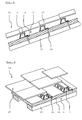
- Fig. 3 is a front view of the insulation board module 17 with the inventive profile 1 and the insulation board 16 is shown.
- the profile 1 has a plurality of recesses 10 in a trapezoidal shape with two side edges 11, an upper edge 20 and a lower edge 21.
- a rectilinear section 22 of the upper edge 20 of the stabilizing strip 13 is formed, which is angled aligned to a arranged on the upper edge 20 portion of the support portion 7.
- no angled aligned stabilizing strip is arranged to facilitate a drainage of liquid on the insulating layer 2 through the recesses 10.
- the profile 1 also has a plurality of recesses 10 in a triangular shape, which also have the upper edge 20 and the side edges 11, each with a stabilizing strip 13.
- the profile 1 are designed to be particularly stable.
- a determination of elements of the roof covering on the profile 1 is facilitated.
- the individual elements of the roofing can be quickly, easily and reliably arranged on the profile 1 and connected to it.
- Fig. 4 is a view of two side by side arranged Dämmplattenmodule 17 is shown for illustrative purposes.
- the Dämmplattenmodule 17 have adapted to each other projecting portions that can serve as a fastening device 23, with the aid of which adjacently arranged Dämmplattenmodule 17 can be fixed to each other in a simple manner.
- the insulation board modules 17 may also have tongue and groove connections or dovetail-shaped undercuts to allow the most stable and permanent attachment to each other.
- Fig. 5 and Fig. 6 show views of a roof structure 24 with the arranged on a roof structure 25 insulation board module 17, the invention according to the insulation board 16 and the profile 1.
- the insulation board module 17 is fixed by fastening means 26 on the roof structure 25.
- the fastening means 26 may be, for example, a fastening screw with a self-tapping thread, which is performed during assembly by the support sections 3 and 4 and is brought into engagement with the roof structure 25 at any point. It is also possible that in the support sections 3 and 4 overlapping arranged openings are formed through which a fastening screw can be screwed into the roof structure 25.
- the fastening means 26 may be, for example, a fastening nail or a Befest Trentskrampe.
- a roof covering 27 consisting of several overlapping roof tiles is fixed to the profiles 1 of the insulation board module 17.
- the insulation board module 17 By such an arrangement of the insulation board module 17 on the roof structure 25, a simple installation of the roof covering 27 is made possible. Due to the insulation board module 17 according to the invention, condensed moisture or liquid can flow away between the roof covering 27 and the insulation board 16 and the roof construction 24 can be ventilated.
- Fig. 7 shows a view of the profile 1 according to the invention with a arranged on the support portion 4 sealing lip 28th
- Fig. 8 shows the insulation board module 17 according to the invention, wherein the in Fig. 7 profile 1 shown has a arranged on the underside on the lower support portion 4 sealing lip 28.
- the sealing lip 28 prevents moisture or condensation between the underside of the support portion 4 and the insulation board 16 can accumulate or penetrate by capillary forces into narrow gaps between the support portion 4 and the insulation board 16.
- a ventilation of the insulation board module 17 and its drying is favored after a moisture formation in this area, so that the assembled profile 1 is even more weather resistant.
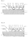
- FIGS. 9 and 10 show front views of the insulation board modules 17 with an alternatively designed profile 1.
- the profile 1 additionally has some circular openings 29 which are arranged on the profile 1 alternately with the openings 10 according to the invention.
- the circular openings 29 may have along their circumference a depressed or partially angled peripheral edge and thereby additionally stabilize the profile 1 according to the invention. It is also conceivable that in addition to the openings 10 further openings are provided with a differently designed shape or with partially rounded extending peripheral edges.
Abstract
Die Erfindung betrifft ein Profil (1) für eine belüftete Dachkonstruktion (24) zur Anordnung zwischen einer Dämmschicht (2) und einer darauf angeordneten Dachdeckung (27), wobei das Profil zwei Auflageabschnitte (3,4) zum Auflegen des Profils auf die Dämmschicht und einen Stützabschnitt (5) aufweist, wobei der Stützabschnitt beabstandet zu der Dämmschicht angeordnet ist und auf dem Stützabschnitt die Dachdeckung abgestützt werden kann, wobei der Stützabschnitt jeweils längs einander gegenüberliegenden Längsrändern (6,8) über jeweils einen Tragabschnitt (7,9) mit den Auflageabschnitten verbunden ist, wobei in den beiden Tragabschnitten jeweils Ausnehmungen (10) angeordnet sind, um eine Durchlüftung der Dachkonstruktion zu ermöglichen, wobei mindestens einige Ausnehmungen mindestens eine von dem Auflageabschnitt in Richtung zu dem Stützabschnitt verlaufende Seitenkante aufweisen und in einem geradlinig verlaufenden Abschnitt der Seitenkante ein abgewinkelter Stabilisierungsstreifen ausgebildet ist. Desweiteren betrifft die Erfindung eine belüftete Dachkonstruktion (24), die eine Dämmschicht (2) sowie eine Dachdeckung (27) und ein dazwischen angeordnetes Profil (1) wie oben beschrieben aufweist, und an einem Dachtragwerk (25) festgelegt werden kannThe invention relates to a profile (1) for a ventilated roof construction (24) for arrangement between an insulating layer (2) and a roof covering (27) arranged thereon, wherein the profile has two support sections (3,4) for placing the profile on the insulating layer and a support portion (5), wherein the support portion is arranged spaced from the insulating layer and on the support portion, the roof covering can be supported, wherein the support portion in each case along longitudinal edges (6,8) over a respective support portion (7,9) with the Recess sections are connected, wherein in the two support portions each recesses (10) are arranged to allow ventilation of the roof structure, wherein at least some recesses have at least one of the support portion extending toward the support portion side edge and in a rectilinear portion of the side edge an angled stabilizer is formed ungsstreifen. Furthermore, the invention relates to a ventilated roof structure (24) having an insulating layer (2) and a roof covering (27) and a profile (1) arranged therebetween as described above, and can be fixed to a roof structure (25)
Description
Die Erfindung betrifft ein Profil für eine belüftete Dachkonstruktion zur Anordnung zwischen einer Dämmschicht und einer darauf angeordneten Dachdeckung, wobei das Profil zwei Auflageabschnitte zum Auflegen des Profils auf die Dämmschicht und einen Stützabschnitt aufweist, wobei der Stützabschnitt beabstandet zu der Dämmschicht angeordnet ist und auf dem Stützabschnitt die Dachdeckung abgestützt werden kann, wenn das Profil bestimmungsgemäß auf der Dämmschicht angeordnet ist, wobei der Stützabschnitt jeweils längs einander gegenüberliegenden Längsrändern über jeweils einen Tragabschnitt mit den Auflageabschnitten verbunden ist, so dass die beiden Auflageabschnitte jeweils über einen Tragabschnitt mit dem Stützabschnitt verbunden sind, wobei in den beiden Tragabschnitten jeweils Ausnehmungen angeordnet sind, um eine Hinterlüftung der Dachdeckung zu ermöglichen, und wobei mindestens einige Ausnehmungen mindestens eine von dem Auflageabschnitt in Richtung zu dem Stützabschnitt verlaufende Seitenkante aufweisen.The invention relates to a profile for a ventilated roof construction for arrangement between an insulating layer and a roof covering thereon, wherein the profile has two support portions for placing the profile on the insulating layer and a support portion, wherein the support portion is arranged spaced from the insulating layer and on the support portion the roof covering can be supported if the profile is intended to be arranged on the insulating layer, wherein the support section is connected in each case along longitudinal edges opposite one another via a support section with the support sections, so that the two support sections are each connected to the support section via a support section, wherein In each of the two support portions recesses are arranged to allow ventilation of the roof covering, and wherein at least some recesses at least one of the support portion in the direction of the Stü Have tzabschnitt extending side edge.
Profile für belüftete Dachkonstruktionen sind aus der Praxis bereits bekannt. Diese Profile werden auf der Dämmschicht angeordnet und bilden ein Auflager für die Dachdeckung. Auf diese Weise kann die Dachdeckung beabstandet zu der Dämmschicht angeordnet werden, um eine Hinterlüftung der Dachdeckung zu ermöglichen. Der Abstand zwischen der Dachdeckung und der Dämmschicht dient dabei unter anderem dazu, eventuell durch die Dachdeckung eindringendes Regenwasser oder sich an einer Unterseite der Dachdeckung ansammelndes Tauwasser sicher abzuleiten und Feuchtigkeit zwischen der Dachdeckung und der Dämmschicht abzuführen.Profiles for ventilated roof structures are already known from practice. These profiles are arranged on the insulating layer and form a support for the roofing. In this way, the roof covering can be arranged spaced from the insulating layer, to allow ventilation of the roof covering. The distance between the roofing and the insulating layer serves, inter alia, to safely drain any rainwater entering through the roofing or condensation water accumulating on a lower side of the roofing and to dissipate moisture between the roofing and the insulating layer.
Die Profile werden mit den Auflageabschnitten auf der Dämmschicht angeordnet, so dass der Stützabschnitt des Profils zur Lagerung der Dachdeckung beabstandet zu der Dämmschicht angeordnet ist. Die Profile können vorab mit der Dämmschicht verbunden und anschließend mit der Dämmschicht auf dem Dachtragwerk befestigt werden. Zur Befestigung der Profile und der Dämmschicht können beispielsweise Schrauben verwendet werden, die durch die Profile und den jeweils zugeordneten Bereich der Dämmschicht in einem Dachtragwerk festgelegt werden können, auf das die Dämmschicht aufgelegt wird. Anschließend können einzelne Dachziegel oder Dachsteine oder dergleichen, welche die Dachdeckung bilden, auf die Stützabschnitte der Profile aufgelegt und beispielsweise durch Drahtclips an den Profilen festgelegt werden.The profiles are arranged with the support portions on the insulating layer, so that the support portion of the profile for supporting the roof covering is arranged spaced from the insulating layer. The profiles can be connected in advance with the insulating layer and then fixed with the insulating layer on the roof structure. For fastening the profiles and the insulating layer, for example screws can be used, which can be determined by the profiles and the respectively associated region of the insulating layer in a roof structure on which the insulating layer is placed. Subsequently, individual roof tiles or roof tiles or the like, which form the roofing, on the support sections the profiles are placed and fixed for example by wire clips on the profiles.
Die Profile werden in der Praxis aus einem Blech oder Metallstreifen hergestellt, der durch Ausstanzen und Rollformen oder mehrfaches Abkanten zu einem Profil mit Auflageabschnitten, mit Tragabschnitten und mit einem Stützabschnitt verformt wird. In den Tragabschnitten der Profile sind dabei regelmäßig mehrere Ausnehmungen angeordnet, um zum einen eine Durchlüftung der Dachkonstruktion und zum anderen um ein Abfließen der zwischen der Dämmschicht und der Dachdeckung kondensierten Flüssigkeit durch die Ausnehmungen in dem Profil zu ermöglichen. Um eine möglichst effiziente Durchlüftung zu ermöglichen müssen die Tragabschnitte möglichst viele, bzw. möglichst großflächige Ausnehmungen aufweisen. Das Profil und insbesondere die Tragabschnitte müssen dennoch stabil ausgestaltet sein, um das Gewicht der Dachdeckung sowie während der Montage der Dachdeckung auch das Gewicht von auf dem Profil stehenden Person tragen zu können. Um eine ausreichende Stabilität gewährleisten zu können sind die aus der Praxis bekannten Profile üblicherweise aus einem ausreichend dicken Blech oder Metallstreifen hergestellt und weisen eine Anzahl von zum Stützabschnitt hin abgerundeten Ausnehmungen auf.The profiles are made in practice from a sheet metal or metal strip, which is deformed by punching and roll forming or multiple folding to a profile with support sections, with support sections and with a support section. In the support sections of the profiles a plurality of recesses are regularly arranged to allow for a ventilation of the roof construction and on the other to drain the condensed between the insulation layer and the roof covering liquid through the recesses in the profile. In order to allow the most efficient possible ventilation, the support sections must have as many or as large as possible recesses. The profile and in particular the support sections must nevertheless be designed to be stable in order to be able to bear the weight of the roof covering as well as the weight of persons standing on the profile during installation of the roof covering. In order to be able to ensure sufficient stability, the profiles known from practice are usually made of a sufficiently thick sheet metal or metal strip and have a number of recesses rounded off towards the support section.
Die zu dem Stützabschnitt hin abgerundete Form der Ausnehmungen führt jedoch dazu, dass die beispielsweise durch einen Drahtclip hergestellte Verbindung eines Elements der Dachdeckung mit dem Profil möglichst in einem mittleren Bereich einer Ausnehmung festgelegt wird, in welchem der Abstand der Ausnehmung zu dem darüber befindlichen Stützabschnitt klein ist. Seitlich beabstandet dazu angeordnete Befestigungsmittel wie ein Drahtclip oder eine manuell gefertigte Drahtschlinge könnten zur Mitte hin Verrutschen und sich dabei lockern. Der Materialaufwand für die Profile und der Montageaufwand für die Befestigung der Dachdeckung auf diesen Profilen sind erheblich.However, the rounded to the support portion shape of the recesses leads to the example made by a wire clip connection of an element of the roof covering with the profile is set as possible in a central region of a recess in which the distance of the recess to the overlying support section small is. Laterally spaced fixing means such as a wire clip or a manually made wire loop could slip towards the center and loosen. The cost of materials for the profiles and the assembly costs for fixing the roof covering on these profiles are significant.
Es wird deshalb als eine Aufgabe der vorliegenden Erfindung angesehen, ein Profil für eine belüftete Dachkonstruktion zur Anordnung zwischen einer Dämmschicht und einer darauf angeordneten Dachdeckung derart auszugestalten, dass eine möglichst einfache und zuverlässige Verbindung der Dachdeckung mit dem Profil und eine möglichst hohe Stabilität des Profils ermöglicht werden.It is therefore regarded as an object of the present invention to design a profile for a ventilated roof structure for the arrangement between an insulating layer and a roof covering thereon such that the simplest possible and reliable connection of the roof covering with the profile and the highest possible stability of the profile possible become.
Eine weitere Aufgabe der Erfindung besteht darin, eine belüftete Dachkonstruktion bereit zu stellen, die eine Dämmschicht sowie eine Dachdeckung und ein dazwischen angeordnetes Profil aufweist, und an einem Dachtragwerk festgelegt werden kann, wobei die belüftete Dachkonstruktion einfach zu montieren ist und eine hohe Stabilität aufweist, und zudem eine verminderte Korrosion der Profile und ein vermindertes Eindringen von Flüssigkeit in die Dämmschicht aufweist.Another object of the invention is to provide a ventilated roof structure having an insulating layer and a roofing and a profile therebetween, and can be fixed to a roof structure, wherein the ventilated roof construction is easy to assemble and has a high stability, and also has a reduced corrosion of the profiles and a reduced penetration of liquid into the insulating layer.
Die Aufgabe der vorliegenden Erfindung wird dadurch gelöst, dass in einem geradlinig verlaufenden Abschnitt der Seitenkante ein Stabilisierungsstreifen ausgebildet ist, der abgewinkelt zu einem an der Seitenkante angeordneten Bereich des Tragabschnitts ausgerichtet ist. Durch den an der Seitenkante ausgebildeten Stabilisierungsstreifen kann das Profil zusätzlich stabilisiert werden, so dass das Profil das Gewicht einer Person bei der Montage des Profils sowie das Gewicht der Dachdeckung tragen kann. Zusätzlich wird durch den Stabilisierungsstreifen die Gefahr einer Schnittverletzung an der Seitenkante der Ausnehmung reduziert und des Weiteren kann das Profil auf einfache Weise hergestellt werden, ohne durch zusätzliche Stabilisierungsmaßnahmen die Herstellungskosten zu erhöhen. Durch die gradlinig verlaufende Seitenkante weist die Ausnehmung eine geringere Abrundung auf, so dass ein größerer Bereich zum Stützabschnitt hin eine zumindest näherungsweise gleichbleibende Breite aufweist und dort dadurch eine einfache und zuverlässige Befestigung der Dachdeckung erleichtert wird.The object of the present invention is achieved in that in a rectilinear section of the side edge, a stabilizing strip is formed, which is angled aligned to a arranged on the side edge portion of the support portion. By stabilizing strips formed on the side edge, the profile can be additionally stabilized, so that the profile can bear the weight of a person during the assembly of the profile and the weight of the roof covering. In addition, the stabilization strip reduces the risk of a cut injury on the side edge of the recess, and furthermore the profile can be produced in a simple manner without increasing the production costs by additional stabilization measures. Due to the rectilinear side edge, the recess has a smaller rounding, so that a larger area towards the support portion has an at least approximately constant width and there is thereby facilitated a simple and reliable attachment of the roof covering.
Um einen Korrosionsschutz des üblicherweise aus Blech, bzw. aus einem Metall hergestellten Profils zu erhöhen, kann das Profil zusätzlich mit einem schützenden Überzug oder mit einer Beschichtung versehen sein. In vielen Fällen ist eine Beschichtung mit Zink, mit einer Zink-Aluminiumlegierung, mit einer Aluminium-Zinklegierung oder mit Zink-Magnesiumlegierung zweckdienlich. Das Profil kann jedoch auch aus einem anderen Material wie beispielsweise Kunststoff hergestellt sein.In order to increase the corrosion protection of the profile usually made of sheet metal or of a metal, the profile may additionally be provided with a protective coating or with a coating. In many cases, a coating with zinc, with a zinc-aluminum alloy, with an aluminum-zinc alloy or zinc-magnesium alloy is useful. However, the profile can also be made of a different material such as plastic.
In vorteilhafter Weise ist vorgesehen, dass der Stabilisierungsstreifen abgewinkelt von einem an den geradlinigen Abschnitt der Seitenkante angrenzenden Bereich des Tragabschnitts in einen durch den Stützabschnitt und die Tragabschnitte gebildeten Innenraum des Profils ragt. Durch die nach innen in einen von dem Profil gebildeten Innenraum ragenden Stabilisierungsstreifen wird die Handhabung der Profile und eine manuelle Befestigung einzelner Elemente der Dachdeckung zusätzlich erleichtert und angenehmer gestaltet, da in den Bereichen der Stabilisierungsstreifen weder nach außen vorspringende Blechabschnitte noch von außen einfach zugängliche scharfkantige und verletzungsgefährdende Blechränder vorgesehen sind. Die abgewinkelten Stabilisierungsstreifen können beispielsweise durch Abkanten oder Eindrücken mit einem Stempelwerkzeug hergestellt sein.It is advantageously provided that the stabilization strip projects at an angle from an area of the support section adjoining the rectilinear section of the side edge into an interior space of the profile formed by the support section and the support sections. By projecting into an inner space formed by the profile interior stabilizing strips, the handling of the profiles and manual attachment of individual elements of the roofing is additionally facilitated and made more pleasant, since in the areas of the stabilizing strip neither after outside projecting sheet metal sections are still provided from the outside easily accessible sharp-edged and injury-prone sheet edges. The angled stabilizing strips can be produced, for example, by folding or pressing in with a stamping tool.
Erfindungsgemäß ist des Weiteren vorgesehen, dass die Ausnehmungen mit einer von dem Auflageabschnitt in Richtung zu dem Stützabschnitt verlaufenden Seitenkante eine zu der Seitenkante benachbarte und dem Stützabschnitt zugewandte Oberkante aufweisen, wobei in einem geradlinig verlaufenden Abschnitt der Oberkante ein Stabilisierungsstreifen ausgebildet ist, der abgewinkelt zu einem an der Oberkante angeordneten Bereich des Tragabschnitts ausgerichtet ist.According to the invention, it is furthermore provided that the recesses have a top edge adjacent to the side edge and facing the support section, with a side edge extending from the support section toward the support section, wherein a stabilization strip is formed in a rectilinear section of the top edge, which angled toward one aligned at the top edge of the support portion is aligned.
Der Stabilisierungsstreifen an der dem Stützabschnitt zugewandten Oberkante ermöglicht, dass das Profil zusätzlich stabilisiert wird. Durch die erfindungsgemäße Ausgestaltung der Oberkante ist der Abstand zwischen dem Stützabschnitt bzw. zwischen dem Längsrand des Stützabschnitts und der Oberkante über einen längeren Abschnitt des Profils hinweg konstant, so dass eine Verbindung der Dachdeckung mit dem Profil beispielsweise durch Drahtclips an jedem Punkt längs der gradlinig verlaufenden Oberkanten zuverlässig möglich ist und sich mit der Zeit weder seitlich verlagert noch lockert.The stabilizing strip on the upper edge facing the support section allows the profile to be additionally stabilized. Due to the inventive design of the upper edge of the distance between the support portion and between the longitudinal edge of the support portion and the upper edge over a longer portion of the profile is constant away, so that a compound of the roof covering with the profile, for example by wire clips at each point along the straight line Upper edges is reliably possible and does not shift laterally or loosens over time.
Gemäß einer vorteilhaften Ausgestaltung des Erfindungsgedankens ist vorgesehen, dass mindestens einige Ausnehmungen auf dem Tragabschnitt zwei von dem Auflageabschnitt in Richtung zu dem Stützabschnitt verlaufende Seitenkanten aufweisen, wobei jeweils in einem geradlinig verlaufenden Abschnitt der zwei Seitenkanten ein Stabilisierungsstreifen ausgebildet ist, der abgewinkelt zu einem der entsprechenden Seitenkante zugeordneten Bereich des Tragabschnitts ausgerichtet ist. Durch zwei benachbarte und beispielsweise durch die Oberkante verbundene Seitenkanten kann das erfindungsgemäße Profil zusätzlich stabilisiert werden und die Gefahr einer Schnittverletzung durch die zweckmäßigerweise nach innen ragenden Stabilisierungsstreifen weiter reduziert werden. Die Stabilisierungsstreifen an den Seitenkanten können übereinstimmend ausgestaltet sein und beispielsweise wenige Millimeter von dem Tragabschnitt aus in einen durch die Auflageabschnitte, den Stützabschnitt und die Tragabschnitte gebildeten Innenraum des Profils hineinragen. Erfindungsgemäß ist des Weiteren vorgesehen, dass mindestens einige Ausnehmungen in den Tragabschnitten eine dem Stützabschnitt abgewandte und zu der Seitenkante benachbarte Unterkante aufweisen, wobei die Unterkante keinen abgewinkelt ausgerichteten Stabilisierungsstreifen aufweist, um ein Abfließen von Flüssigkeit auf der Dämmschicht durch die Ausnehmungen zu erleichtern. Durch eine derartige Ausgestaltung der die zwei Seitenkanten verbindenden Unterkante kann die in der Dachkonstruktion zwischen der Dämmschicht und der Dachdeckung kondensierte Flüssigkeit auf einfache Weise durch die Ausnehmungen des Profils nach unten abfließen. Eine Korrosion der Profile sowie ein Eindringen der Flüssigkeit in die Dämmschicht werden vorteilhaft vermindert.According to an advantageous embodiment of the inventive concept, it is provided that at least some recesses on the support section have two side edges extending from the support section towards the support section, wherein in each case a stabilizing strip is formed in a rectilinear section of the two side edges, which is angled toward one of the corresponding Side edge associated with the area of the support section is aligned. By two adjacent and connected for example by the upper edge side edges profile of the invention can be additionally stabilized and the risk of a cut injury by the expediently inwardly projecting stabilizing strips are further reduced. The stabilizing strips on the side edges can be configured in a matching manner and protrude, for example, a few millimeters from the support section into an interior space of the profile formed by the support sections, the support section and the support sections. According to the invention, it is further provided that at least some recesses in the support sections have a lower edge facing away from the support section and adjacent to the side edge, wherein the lower edge has no angled aligned stabilizing strips to facilitate a drainage of liquid on the insulating layer through the recesses. By such a configuration of the lower edge connecting the two side edges, the liquid condensed in the roof construction between the insulating layer and the roof covering can flow down in a simple manner through the recesses of the profile. Corrosion of the profiles and penetration of the liquid into the insulating layer are advantageously reduced.
Einer besonders vorteilhaften Ausgestaltung des erfindungsgemäßen Profils zufolge ist vorgesehen, dass mindestens einige Ausnehmungen, die in den Tragabschnitten angeordnet sind, eine Dreieckform aufweisen und dass eine dem Stützabschnitt zugewandte Dreieckseitenkante der dreieckigen Ausnehmung parallel zu dem Längsrand des Stützabschnitts ausgerichtet ist. Eine parallel zu dem Längsrand ausgerichtete Dreieckseitenkante ermöglicht eine Verbindung der Dachdeckung mit dem Profil wahlweise auf einem der zahlreichen längeren Abschnitte der oben verlaufenden Dreieckseitenkanten des Profils. Die Verbindung der Dachdeckung mit dem Profil verändert sich auf Grund des gleichen Abstands zwischen der Dreieckseitenkante und dem Längsrand oder der Oberseite des Stützabschnitts auch bei einer Verschiebung einzelner Elemente der Dachdeckung oder einzelner Befestigungsmittel entlang des Profils nicht und ermöglicht eine gleichbleibend zuverlässige Festlegung der Dachdeckung an dem Profil. Des Weiteren ermöglicht der an der Dreieckseitenkante ausgebildete Stabilisierungsstreifen eine zusätzliche Stabilisierung des Profils. Durch eine geeignete Vorgabe des Materials und der Stärke des Profils können das Gewicht einer Person bei der Montage der Dachkonstruktion sowie das Gewicht der Dachdeckung einschließlich einer üblichen Schneelast ohne jegliche Verformung des Profils aufgenommen und abgetragen werden. Durch die Formgebung der Ausnehmungen und die Ausbildung gradlinig verlaufender Seitenkanten mit Stabilisierungsstreifen wird auch die Gefahr einer Schnittverletzung der an der Montage der Dachkonstruktion beteiligten Personen reduziert.According to a particularly advantageous embodiment of the profile according to the invention, it is provided that at least some recesses which are arranged in the support sections have a triangular shape and that a triangular side edge of the triangular recess facing the support section is aligned parallel to the longitudinal edge of the support section. An aligned parallel to the longitudinal edge triangle side edge allows a connection of the roof covering with the profile optionally on one of the numerous longer portions of the above-running triangle side edges of the profile. The connection of the roof covering with the profile does not change due to the same distance between the triangle side edge and the longitudinal edge or the top of the support portion even with a shift of individual elements of the roof covering or individual fasteners along the profile and allows a consistently reliable determination of the roof covering on the Profile. Furthermore, the stabilization strip formed on the triangle side edge enables additional stabilization of the profile. By a suitable specification of the material and the strength of the profile, the weight of a person in the assembly of the roof structure and the weight of the roof covering including a conventional snow load without any deformation of the profile can be absorbed and removed. Due to the shape of the recesses and the formation of rectilinear side edges with stabilizing strips and the risk of cutting injury of persons involved in the assembly of the roof construction is reduced.
Erfindungsgemäß ist vorgesehen, dass mindestens einige Ausnehmungen, die in den Tragabschnitten angeordnet sind, eine Trapezform aufweisen und dass eine dem Stützabschnitt zugewandte Trapezseitenkante der trapezförmigen Ausnehmung parallel zu dem Längsrand des Stützabschnitts ausgerichtet ist. Durch die trapezförmige Ausgestaltung der Ausnehmungen wird ermöglicht, dass zum einen der Abstand der Trapezseitenkante zu dem Längsrand des Stützabschnitts konstant bleibt und dass zum anderen das Profil durch den an der Trapezseitenkante ausgebildeten Stabilisierungsstreifen zusätzlich stabilisiert wird. Des Weiteren ermöglicht eine Trapezunterkante, die erfindungsgemäß an den Auflageabschnitten angeordnet ist und keinen Stabilisierungsstreifen aufweist, ein Abfließen der zwischen der Dachdeckung und der Dämmschicht kondensierten Flüssigkeit. Besonders vorteilhaft ist eine abwechselnde Anordnung von dreieckförmigen und trapezförmigen Ausnehmungen, so dass jeweils nur schmale gradlinig verlaufende Stegabschnitte zwischen den aufeinanderfolgenden Ausnehmungen verbleiben, an denen zu beiden Seiten Stabilisierungsstreifen abgewinkelt sind.According to the invention, it is provided that at least some recesses which are arranged in the support sections have a trapezoidal shape and that a trapezoid side edge of the trapezoidal recess facing the support section is parallel is aligned with the longitudinal edge of the support portion. The trapezoidal configuration of the recesses makes it possible, on the one hand, for the spacing of the trapezoid side edge to the longitudinal edge of the support section to remain constant, and for, on the other hand, the profile is additionally stabilized by the stabilization strip formed on the trapezoid side edge. Furthermore, a lower trapezoidal edge, which is arranged according to the invention on the support sections and has no stabilizing strip, allows the fluid condensed between the roofing and the insulating layer to flow away. Particularly advantageous is an alternating arrangement of triangular and trapezoidal recesses, so that in each case only narrow rectilinear web portions remain between the successive recesses on which stabilizing strips are angled on both sides.
Die Ausnehmungen können sich an der Unterseite jeweils über den Tragabschnitt hinweg bis hinein in einen angrenzenden Auflageabschnitt erstrecken, so dass unten befindliche bzw. der Dämmschicht zugewandte Randabschnitte der Ausnehmungen keinesfalls nach oben vorspringend ausgebildet sein können, sondern zuverlässig eng anliegend auf der Dämmschicht verlaufen.The recesses may extend on the underside over the support portion all the way into an adjoining support section, so that the edge portions of the recesses facing below or the insulation layer can not in any case project upwards, but reliably run tightly against the insulation layer.
Bei einer besonders vorteilhaften Ausgestaltung des erfindungsgemäßen Profils ist vorgesehen, dass die Auflageabschnitte in derselben Richtung ausgerichtet sind und abschnittsweise aneinander anliegen, wobei der untere Auflageabschnitt an der Dämmschicht anliegt und der obere Auflageabschnitt an dem unteren Auflageabschnitt anliegt, wenn das Profil auf der Dämmschicht angeordnet ist, und wobei der obere Auflageabschnitt über den unteren Auflageabschnitt hinausragt und an seiner hinausragenden Abschnittsseitenkante einen nach unten abgewinkelt ausgerichteten Krallstreifen für einen formschlüssigen Eingriff mit der Dämmschicht aufweist.In a particularly advantageous embodiment of the profile according to the invention it is provided that the support portions are aligned in the same direction and abut each other in sections, the lower support portion abuts the insulation layer and the upper support portion rests against the lower support portion when the profile is disposed on the insulating layer , and wherein the upper support portion protrudes beyond the lower support portion and has at its protruding portion side edge a downwardly angled aligned Krallstreifen for a positive engagement with the insulating layer.
Durch den nach unten abgewinkelt ausgerichteten Krallstreifen kann das Profil formschlüssig beispielsweise in einer daran angepassten Nut in der Dämmschicht oder an einem Rand der Dämmschicht festgelegt werden. Der Krallstreifen kann beispielsweise durch Abkanten oder Rollformen eines Randbereichs an dem oberen Auflageabschnitt ausgebildet sein und eine kleinere Höhe als die Dicke der Dämmschicht aufweisen, um die Dämmschicht durch die formschlüssige Verbindung des Krallstreifens in der Dämmschicht nicht übermäßig zu schwächen.As a result of the claw strip, which is angled downwards, the profile can be fixed in a form-fitting manner, for example, in an adapted groove in the insulating layer or at an edge of the insulating layer. The claw strip may be formed, for example, by folding or roll forming a border region on the upper support portion and having a smaller height than the thickness of the insulating layer so as not to unduly weaken the insulating layer by the positive connection of the Krall strip in the insulating layer.
Einzelne Dämmschichtelemente können mit in regelmäßigen Abständen parallel zueinander verlaufenden Profilen versehen und vorgefertigt werden, so dass der vor Ort für die Dachkonstruktion anfallende Montageaufwand reduziert werden kann. Anschließend müssen lediglich die einzelnen Elemente der Dachdeckung an den einzelnen Profilen beispielsweise durch Drahtclips festgelegt werden.Individual insulating layer elements can be provided and prefabricated with at regular intervals parallel to each other profiles, so that the costs incurred locally for the roof construction assembly work can be reduced. Subsequently, only the individual elements of the roof covering must be fixed to the individual profiles, for example by wire clips.
Die beiden aneinander anliegend angeordneten Auflageabschnitte des Profils ermöglichen es in Verbindung mit dem seitlich vorspringend angeordneten Krallstreifen, dass abzuführende Flüssigkeit auf dem längeren oberen Auflageabschnitt abfließen kann und nicht zwischen die beiden Auflageabschnitte eindringt.The two adjacent bearing portions of the profile allow, in conjunction with the laterally projecting arranged claw strip that liquid to be discharged can flow on the longer upper support portion and does not penetrate between the two support portions.
Erfindungsgemäß können die Auflageabschnitte entweder nicht miteinander verbunden sein oder aber kraftschlüssig und/oder stoffschlüssig beispielweise durch Durchsetzfügen, Clinchen, Kleben, Schrauben, Punktschweißen, Rändeln oder ähnlich miteinander verbunden und aneinander festgelegt sein, um eine unerwünschte Verformung des Profils bei der Montage oder beim Transport zu vermeiden und um ein Eindringen der Flüssigkeit zwischen den aneinander anliegenden Auflageabschnitten zusätzlich zu erschweren, bzw. zu verhindern.According to the invention, the support sections can either not be connected to one another or can be non-positively and / or materially joined, for example by clinching, clinching, gluing, screwing, spot welding, knurling or the like, and fixed to one another to prevent undesired deformation of the profile during assembly or during transport to avoid and in addition to complicate the penetration of the liquid between the adjoining support sections, or to prevent.
Um eine Befestigung des Profils zu erleichtern ist vorgesehen, dass das Profil an den Auflageabschnitten mindestens teilweise überlappend angeordnete Öffnungen aufweist, um das Profil und die Dämmschicht mit Hilfe eines Befestigungsmittels, dass durch einen von in den überlappenden Öffnungen gebildeten Durchgriff angeordnet ist, an einem Dachtragwerk festlegen zu können. Die überlappend angeordneten Öffnungen können in dem erfindungsgemäßen Profil bereits vor oder nach der Ausformung des Profils aus einem flachen Zuschnitt ausgestanzt sein. Durch die überlappend an dem Profil angeordneten Öffnungen können die Montage der Dämmschicht und des Profils an dem Dachtragwerk vereinfacht werden und der Zeit- sowie der Arbeitsaufwand reduziert werden. Es ist ebenfalls möglich, die Öffnungen durch zungenförmige Ausstanzen auszubilden, die anschießend gemeinsam abgekantet, abgewinkelt oder durchgedrückt werden, um die Öffnungen herzustellen und gleichzeitig die beiden übereinander angeordneten Auflageabschnitte miteinander zu verbinden.In order to facilitate attachment of the profile, provision is made for the profile to have at least partially overlapping openings on the support sections in order to secure the profile and the insulating layer to a roof structure by means of a fastening means arranged through a passage formed in the overlapping openings to be able to determine. The overlapping arranged openings can be punched in the profile according to the invention already before or after the formation of the profile of a flat blank. By overlapping arranged on the profile openings, the mounting of the insulating layer and the profile can be simplified to the roof structure and the time and labor costs are reduced. It is also possible to form the openings by tongue-shaped punching, which are anschießend together bent, angled or pressed to produce the openings and at the same time to connect the two superimposed support portions together.
Um die beiden übereinander angeordneten Auflageabschnitte kostengünstig und zuverlässig miteinander verbinden zu können ist es ebenfalls denkbar, dass an dem oberen Auflageabschnitt eine nach unten gerichtete und durch die Öffnung in den unteren Auflageabschnitt ragende Ausformung ausgebildet ist. Die Ausformung kann beispielsweise eine in der Öffnung des oberen Auflageabschnitts ausgebildete Zunge sein, die nach unten durch die Öffnung des unteren Auflageabschnitts abgewinkelt oder eingedrückt ist, so dass die aus dem oberen Auflageabschnitt ragende Zunge einen formschlüssigen Eingriff mit dem unteren Auflageabschnitt bildet. Es ist ebenfalls denkbar, dass ein Öffnungsrand des oberen Auflageabschnitts in Richtung des unteren Auflageabschnitts eingedrückt oder verformt wird und einen Eingriff mit der daran angepassten Öffnung in dem unteren Auflageabschnitt bildet.In order to connect the two stacked support sections cost-effectively and reliably, it is also conceivable that at the upper support portion a downwardly directed and through the opening in the lower support section projecting shape is formed. The molding may be, for example, a tongue formed in the opening of the upper support portion which is angled or depressed downward through the opening of the lower support portion so that the tongue protruding from the upper support portion forms a positive engagement with the lower support portion. It is also conceivable that an opening edge of the upper support portion is pressed or deformed in the direction of the lower support portion and forms an engagement with the adapted thereto opening in the lower support portion.
Einer vorteilhaften Ausgestaltung des Erfindungsgedankens zufolge ist es vorgesehen, dass das Profil an einer Unterseite des unteren Auflageabschnitts beabstandet zu dem Krallstreifen eine Dichtungslippe aufweist. Die Dichtungslippe liegt auf einer Oberseite der Dämmschicht auf und verhindert, dass Feuchtigkeit beispielsweise auf Grund von Kapillarkräften in einen Spalt zwischen dem unteren Auflageabschnitt und der Dämmschicht kriecht. Durch die Dichtungslippe kann der Spalt vergrößert werden, so dass der untere Auflageabschnitt nicht mehr unmittelbar auf der Dämmschicht aufliegt, sondern einen kleinen Abstand zu der Dämmschicht aufweist und hinterlüftet werden kann.An advantageous embodiment of the inventive concept, it is provided that the profile at a bottom of the lower support portion spaced from the nip strip has a sealing lip. The sealing lip rests on an upper side of the insulating layer and prevents moisture from creeping, for example due to capillary forces, into a gap between the lower supporting section and the insulating layer. By the sealing lip of the gap can be increased, so that the lower support portion no longer rests directly on the insulating layer, but has a small distance from the insulation layer and can be ventilated.
Die Erfindung betrifft auch ein Dämmplattenmodul mit einer Dämmplatte und mit einem vorangehend beschriebenen Profil, welches kraft- oder formschlüssig an der Dämmplatte festgelegt ist. Die Dämmplatte kann erfindungsgemäß aus einem Werkstoff mit geeigneten Dämmungseigenschaften wie beispielsweise aus Polystyrol, aus Minerallwolle, aus einem geschäumten Kunststoff oder ähnlichem hergestellt sein. Das Profil kann an der Dämmplatte beispielsweise durch Kleben festgelegt sein. Durch eine Vorfertigung des erfindungsgemäßen Dämmplattenmoduls kann vor Ort die Montage der Dachkonstruktion mit wenig Zeit- und Arbeitsaufwand vorgenommen werden, wodurch auch die Montagekosten reduziert werden.The invention also relates to an insulation board module with an insulation board and with a profile described above, which is fixed non-positively or positively on the insulation board. The insulation board according to the invention may be made of a material with suitable insulation properties such as polystyrene, mineral wool, a foamed plastic or the like. The profile can be fixed to the insulation board, for example by gluing. By prefabrication of the insulation board module according to the invention, the installation of the roof structure can be made on site with little time and effort, which also reduces installation costs.
Erfindungsgemäß ist vorgesehen, dass das Profil mit einem zur Dämmplatte hin abgewinkelten Krallstreifen in einer Profilnut der Dämmplatte festgelegt ist. Durch den Krallstreifen kann das Profil erfindungsgemäß in der Dämmplatte formschlüssig angeordnet sein und mit der Dämmplatte zusätzlich beispielsweise verklebt werden. Des Weiteren kann das erfindungsgemäße Dämmplattenmodul Befestigungsvorrichtungen aufweisen, durch die einzelne Dämmplattenmodule miteinander verbunden werden können und dadurch die gesamte Dachkonstruktion aus einzelnen Dämmplattenmodulen schnell und auf einfache Weise hergestellt werden.According to the invention, it is provided that the profile is fixed in a profile groove of the insulation board with a claw strip angled away from the insulation board. By Krallstreifen the profile according to the invention can be arranged in a form-fitting manner in the insulation board and additionally glued to the insulation board, for example. Furthermore, the insulation board module according to the invention may have fastening devices by which individual insulation board modules are connected to one another and thereby the entire roof construction can be made of individual insulation board modules quickly and easily.
Weitere vorteilhafte Ausgestaltungen des erfindungsgemäßen Profil und des erfindungsgemäßen Dämmplattenmoduls sind anhand der in der Zeichnung dargestellten Ausführungsformen näher erläutert. Es zeigt:
- Fig. 1
- eine Seitenansicht eines erfindungsgemäßen Profils,
- Fig. 2
- eine Seitenansicht eines erfindungsgemäßen Dämmplattenmoduls mit einer Dämmschicht und mit dem in
Fig. 1 gezeigten Profil, - Fig. 3
- eine Frontansicht des in
Fig. 2 gezeigten Dämmplattenmoduls, - Fig. 4
- eine Ansicht von zwei nebeneinander angeordneten und miteinander verbundenen Dämmplattenmodulen,
- Fig. 5
- eine Ansicht einer Dachkonstruktion mit einem erfindungsgemäßen Dämmplattenmodul,
- Fig. 6
- eine Ansicht einer Dachkonstruktion mit einem erfindungsgemäßen Dämmplattenmodul,
- Fig. 7
- eine Seitenansicht eines erfindungsgemäßen Profils mit einer Dichtlippe,
- Fig. 8
- eine Seitenansicht eines erfindungsgemäßen Dämmplattenmoduls mit einer Dämmschicht und mit dem in
Fig. 7 gezeigten Profil, und - Fig. 9
und 10 - Frontansichten eines erfindungsgemäßen Dämmplattenmoduls mit einem auch runde Öffnungen aufweisenden Profil.
- Fig. 1
- a side view of a profile according to the invention,
- Fig. 2
- a side view of a Dämmplattenmoduls invention with an insulating layer and with the in
Fig. 1 shown profile, - Fig. 3
- a front view of the in
Fig. 2 shown insulation board module, - Fig. 4
- a view of two juxtaposed and interconnected Dämmplattenmodulen,
- Fig. 5
- a view of a roof construction with a Dämmplattenmodul invention,
- Fig. 6
- a view of a roof construction with a Dämmplattenmodul invention,
- Fig. 7
- a side view of a profile according to the invention with a sealing lip,
- Fig. 8
- a side view of a Dämmplattenmoduls invention with an insulating layer and with the in
Fig. 7 shown profile, and - FIGS. 9 and 10
- Front views of a Dämmplattenmoduls invention with a circular openings also having profile.
In
Das Profil 1 weist einen oberen Auflageabschnitt 3 und einen unteren Auflageabschnitt 4 sowie einen Stützabschnitt 5 auf. Der Stützabschnitt 5 ist beabstandet zu der Dämmschicht 2 angeordnet und auf dem Stützabschnitt 5 kann bestimmungsgemäß ein Element der Dachdeckung, beispielsweise ein Dachstein oder ein Dachziegel abgestützt werden. Der Stützabschnitt 5 ist längs eines Längsrands 6 mit einem Tragabschnitt 7 und längs eines Längsrands 8 mit einem Tragabschnitt 9 verbunden, so dass die beiden in derselben Richtung ausgerichtete Auflageabschnitte 3 und 4 jeweils über die Tragabschnitte 7 und 9 mit dem Stützabschnitt 5 verbunden sind. Die beiden Auflageabschnitte 3 und 4 sind ausreichend lang ausgestaltet, so dass die beiden Auflageabschnitte 3 und 4 bereichsweise aneinander anliegen und in diesem Bereich der ober Auflageabschnitt 3 über dem unteren Auflageabschnitt 4 angeordnet ist. Der obere Auflageabschnitt 3 und der untere Auflageabschnitt 4 können zusätzlich miteinander durch Verkleben, Druckfügen, Clinchen, Durchsetzfügen oder Rändeln verbunden sein, um eine erhöhte Stabilität des Profils 1 zu ermöglichen.The
In den beiden Tragabschnitten 7 und 9 sind jeweils Ausnehmungen 10 angeordnet, um eine Durchlüftung der Dachkonstruktion zu begünstigen. Die Ausnehmungen 10 weisen von den Auflageabschnitten 3 und 4 in Richtung zu dem Stützabschnitt 5 verlaufende Seitenkanten 11 auf, wobei in einem sich fast über die gesamte Seitenkante 11 hinweg erstreckenden geradlinig verlaufenden Abschnitt 12 der Seitenkanten 11 jeweils ein Stabilisierungsstreifen 13 ausgebildet ist. Die Stabilisierungsstreifen 13 sind abgewinkelt zu einem an den Seitenkanten 11 angeordneten Bereich 14 der Tragabschnitte 7 und 9 ausgerichtet. Durch eine derartige Anordnung der Stabilisierungsstreifen 13 an dem Profil 1 wird die Stabilität des Profils 1 erhöht. Weiterhin wird durch die Stabilisierungsstreifen 13 die Gefahr einer Schnittverletzung an den Seitenkanten 11 bei der Montage des erfindungsgemäßen Profil 1 erheblich reduziert.In the two
Bei einer bestimmungsgemäßen Anordnung des Profils 1 auf der Dämmschicht 2 liegt der untere Auflageabschnitt 4 an der Dämmschicht 2 an und der obere Auflageabschnitt 3 liegt auf dem unteren Auflageabschnitt 4 auf, wobei der obere Auflageabschnitt 3 über den unteren Auflageabschnitt 4 hinausragt. In dem hinausragenden Endbereich 14 des oberen Auflageabschnittes 3 ist ein nach unten abgewinkelt ausgerichteter Krallstreifen 15 ausgebildet, der eine formschlüssige Verbindung des Profils 1 mit der Dämmschicht 2 ermöglicht.In a proper arrangement of the
Erfindungsgemäß bildet das Profil 1 und die als eine Dämmplatte 16 ausgebildete Dämmschicht 2 ein Dämmplattenmodul 17. Der in einer Profilnut 18 in der Dämmplatte 16 angeordnete Krallstreifen 15 kann vormontiert und beispielsweise durch Kleben an der Dämmplatte 16 festgelegten werden, wodurch bei einer Verwendung des vorgefertigten erfindungsgemäßen Dämmplattenmoduls 17 die Montage der Dachkonstruktion mit einem geringen Zeit- und Arbeitsaufwand vorgenommen werden kann. An dem oberen Auflageabschnitt 3 und dem unteren Auflageabschnitt 4 ist eine beispielsweise durch ein Durchsetzfügeverfahren ausgebildete Ausformung 19 angeordnet, die nach unten über den unteren Auflageabschnitt 4 hinausragt, um einen formschlüssigen Eingriff zu bilden und den oberen Auflageabschnitt 3 relativ zu dem unteren Auflageabschnitt 4 zu fixieren. Die Ausformung 19 kann ebenso wie der Krallstreifen 15 in die Dämmschicht 2 eindringen und das Profil 1 an der Dämmschicht 2 zusätzlich festlegen.According to the invention, the
In
Des Weiteren weist das Profil 1 ebenfalls mehrere Ausnehmungen 10 in einer Dreieckform auf, die ebenfalls die Oberkannte 20 und die Seitenkanten 11 mit jeweils einem Stabilisierungsstreifen 13 aufweisen. Durch eine abwechselnde Anordnung von dreieckförmigen Ausnehmungen 10 trapezförmigen Ausnehmungen 10 an den Tragabschnitten 7 und 9 können das Eigengewicht des Profils 1 reduziert werden und gleichzeitig durch die sich über weite Abschnitte gradlinig erstreckende Oberkanten 20 mit dem Stabilisierungsstreifen 13 das Profil 1 besonders stabil ausgestaltet werden. Auch eine Festlegung von Elementen der Dachdeckung an dem Profil 1 wird dadurch erleichtert. Die einzelnen Elemente der Dachdeckung können rasch, einfach und zuverlässig an dem Profil 1 angeordnet und damit verbunden werden.Furthermore, the
In
Claims (14)
Applications Claiming Priority (1)
| Application Number | Priority Date | Filing Date | Title |
|---|---|---|---|
| DE201420105633 DE202014105633U1 (en) | 2014-11-21 | 2014-11-21 | Profile for a ventilated roof construction |
Publications (1)
| Publication Number | Publication Date |
|---|---|
| EP3023557A1 true EP3023557A1 (en) | 2016-05-25 |
Family
ID=52623993
Family Applications (1)
| Application Number | Title | Priority Date | Filing Date |
|---|---|---|---|
| EP15195329.6A Withdrawn EP3023557A1 (en) | 2014-11-21 | 2015-11-19 | Profile for a ventilated roof structure |
Country Status (2)
| Country | Link |
|---|---|
| EP (1) | EP3023557A1 (en) |
| DE (1) | DE202014105633U1 (en) |
Cited By (1)
| Publication number | Priority date | Publication date | Assignee | Title |
|---|---|---|---|---|
| US11198772B2 (en) * | 2017-10-31 | 2021-12-14 | Tokyo Ohka Kogyo Co., Ltd. | Surface treatment liquid and surface treatment method |
Citations (8)
| Publication number | Priority date | Publication date | Assignee | Title |
|---|---|---|---|---|
| US2167666A (en) * | 1936-03-21 | 1939-08-01 | Cons Expanded Metal Companies | Structural member |
| DE1056350B (en) * | 1956-11-05 | 1959-04-30 | Franz Berlinger | Device for roof ventilation |
| LU85006A1 (en) * | 1983-08-18 | 1984-03-16 | Max Schiele | SUPPORT BODY FOR ROOF COVER PLATES |
| DE4110408A1 (en) * | 1990-04-03 | 1991-10-10 | Alutect Uersfeld Bauelemente G | Thermal insulation panels for underside of roof - has panels supported on beams which fit contours of panel edges |
| WO2006069435A1 (en) * | 2004-12-27 | 2006-07-06 | Gcg Holdings Ltd. | Floor system with steel joists having openings with edge formations and method |
| US20070056245A1 (en) * | 2004-09-09 | 2007-03-15 | Dennis Edmondson | Slotted metal truss and joist with supplemental flanges |
| US20100287872A1 (en) * | 2009-05-13 | 2010-11-18 | Bodnar Ernest R | Open web stud with low thermal conductivity and screw receiving grooves |
| US8281522B1 (en) * | 2010-09-21 | 2012-10-09 | Andrei Hawryshko | Ventilated roofing system |
-
2014
- 2014-11-21 DE DE201420105633 patent/DE202014105633U1/en not_active Withdrawn - After Issue
-
2015
- 2015-11-19 EP EP15195329.6A patent/EP3023557A1/en not_active Withdrawn
Patent Citations (8)
| Publication number | Priority date | Publication date | Assignee | Title |
|---|---|---|---|---|
| US2167666A (en) * | 1936-03-21 | 1939-08-01 | Cons Expanded Metal Companies | Structural member |
| DE1056350B (en) * | 1956-11-05 | 1959-04-30 | Franz Berlinger | Device for roof ventilation |
| LU85006A1 (en) * | 1983-08-18 | 1984-03-16 | Max Schiele | SUPPORT BODY FOR ROOF COVER PLATES |
| DE4110408A1 (en) * | 1990-04-03 | 1991-10-10 | Alutect Uersfeld Bauelemente G | Thermal insulation panels for underside of roof - has panels supported on beams which fit contours of panel edges |
| US20070056245A1 (en) * | 2004-09-09 | 2007-03-15 | Dennis Edmondson | Slotted metal truss and joist with supplemental flanges |
| WO2006069435A1 (en) * | 2004-12-27 | 2006-07-06 | Gcg Holdings Ltd. | Floor system with steel joists having openings with edge formations and method |
| US20100287872A1 (en) * | 2009-05-13 | 2010-11-18 | Bodnar Ernest R | Open web stud with low thermal conductivity and screw receiving grooves |
| US8281522B1 (en) * | 2010-09-21 | 2012-10-09 | Andrei Hawryshko | Ventilated roofing system |
Cited By (1)
| Publication number | Priority date | Publication date | Assignee | Title |
|---|---|---|---|---|
| US11198772B2 (en) * | 2017-10-31 | 2021-12-14 | Tokyo Ohka Kogyo Co., Ltd. | Surface treatment liquid and surface treatment method |
Also Published As
| Publication number | Publication date |
|---|---|
| DE202014105633U1 (en) | 2015-02-12 |
Similar Documents
| Publication | Publication Date | Title |
|---|---|---|
| EP1734588B1 (en) | Roofing system | |
| EP2186964B1 (en) | Roofing with at least two sheet metals in between of profiles and solar unit on this roofing | |
| EP3293317B1 (en) | Draining device for draining water | |
| EP2492412B1 (en) | Snow and/or ice capturing device | |
| EP2392746B1 (en) | Building panel | |
| EP3023557A1 (en) | Profile for a ventilated roof structure | |
| DE202013100629U1 (en) | web profile | |
| EP3733995B1 (en) | Weather-protected wood floor device | |
| EP2505936A1 (en) | Mounting device for a mounting profile | |
| EP1857605B1 (en) | Floor covering for a building part | |
| DE19910824A1 (en) | Sheet steel drainage channel has removeable cover grid held on cross webs fitted into sides of channel | |
| AT518202A2 (en) | Roofing element and roofing with such | |
| DE10200642B4 (en) | Stormproof roofing system | |
| EP3680413B1 (en) | Assembly with an extruded roof covering element | |
| EP2423405A1 (en) | Standing seam cover | |
| EP1445395B1 (en) | Roof system and method for covering a roof | |
| DE102005029361B3 (en) | Ridge or grating cover element has stiffening profiles arranged in overlapping regions between ventilation elements and fixing strips | |
| DE20220561U1 (en) | Cleaning system, for surfaces exposed to weather, e.g. roofs and facades, has spaced metallic layers with a copper content to form zones to develop compounds against fungi and bacteria to be flushed over exposed areas | |
| EP1191160A1 (en) | Floor drain | |
| DE202005010024U1 (en) | Ridge unroofing unit for ventilated flat roof, has reinforcement profile that is arranged in overlap area, where profile contacts with top side of roofing units that are provided directly adjacent to ridge in installation condition | |
| DE19941510A1 (en) | Roof construction for use on building has several adjacent sheets of metal joined by curled-over edges | |
| EP3385467A1 (en) | Drip edge | |
| DE102019100672A1 (en) | Extruded roofing element | |
| EP2446094B1 (en) | Support section for a facade system | |
| WO2011137915A2 (en) | Clamp fastening of profiles on standing-seam or trapezoidal metal sheets |
Legal Events
| Date | Code | Title | Description |
|---|---|---|---|
| AK | Designated contracting states |
Kind code of ref document: A1 Designated state(s): AL AT BE BG CH CY CZ DE DK EE ES FI FR GB GR HR HU IE IS IT LI LT LU LV MC MK MT NL NO PL PT RO RS SE SI SK SM TR |
|
| AX | Request for extension of the european patent |
Extension state: BA ME |
|
| PUAI | Public reference made under article 153(3) epc to a published international application that has entered the european phase |
Free format text: ORIGINAL CODE: 0009012 |
|
| STAA | Information on the status of an ep patent application or granted ep patent |
Free format text: STATUS: THE APPLICATION HAS BEEN WITHDRAWN |
|
| 18W | Application withdrawn |
Effective date: 20160614 |