EP3023333A1 - Retractable and deployable structure with tape measure - Google Patents
Retractable and deployable structure with tape measure Download PDFInfo
- Publication number
- EP3023333A1 EP3023333A1 EP15195097.9A EP15195097A EP3023333A1 EP 3023333 A1 EP3023333 A1 EP 3023333A1 EP 15195097 A EP15195097 A EP 15195097A EP 3023333 A1 EP3023333 A1 EP 3023333A1
- Authority
- EP
- European Patent Office
- Prior art keywords
- tape measure
- point
- deployable structure
- guide
- axis
- Prior art date
- Legal status (The legal status is an assumption and is not a legal conclusion. Google has not performed a legal analysis and makes no representation as to the accuracy of the status listed.)
- Granted
Links
- 238000010586 diagram Methods 0.000 description 12
- 230000033228 biological regulation Effects 0.000 description 7
- 238000004804 winding Methods 0.000 description 6
- 239000000463 material Substances 0.000 description 4
- 239000012528 membrane Substances 0.000 description 4
- 230000001464 adherent effect Effects 0.000 description 2
- 230000000694 effects Effects 0.000 description 2
- 239000004744 fabric Substances 0.000 description 2
- 238000012423 maintenance Methods 0.000 description 2
- NJPPVKZQTLUDBO-UHFFFAOYSA-N novaluron Chemical group C1=C(Cl)C(OC(F)(F)C(OC(F)(F)F)F)=CC=C1NC(=O)NC(=O)C1=C(F)C=CC=C1F NJPPVKZQTLUDBO-UHFFFAOYSA-N 0.000 description 2
- 230000000750 progressive effect Effects 0.000 description 2
- 229920000049 Carbon (fiber) Polymers 0.000 description 1
- 241000287107 Passer Species 0.000 description 1
- 239000002390 adhesive tape Substances 0.000 description 1
- 238000004873 anchoring Methods 0.000 description 1
- 239000004917 carbon fiber Substances 0.000 description 1
- 230000015556 catabolic process Effects 0.000 description 1
- 230000000295 complement effect Effects 0.000 description 1
- 239000002131 composite material Substances 0.000 description 1
- 230000007423 decrease Effects 0.000 description 1
- 238000006731 degradation reaction Methods 0.000 description 1
- 238000000605 extraction Methods 0.000 description 1
- 230000002349 favourable effect Effects 0.000 description 1
- 239000000835 fiber Substances 0.000 description 1
- 238000010438 heat treatment Methods 0.000 description 1
- VNWKTOKETHGBQD-UHFFFAOYSA-N methane Chemical compound C VNWKTOKETHGBQD-UHFFFAOYSA-N 0.000 description 1
- 238000000034 method Methods 0.000 description 1
- 238000003032 molecular docking Methods 0.000 description 1
- 238000005457 optimization Methods 0.000 description 1
- 238000007747 plating Methods 0.000 description 1
- 230000001105 regulatory effect Effects 0.000 description 1
- 230000000284 resting effect Effects 0.000 description 1
- 230000035939 shock Effects 0.000 description 1
- 230000002269 spontaneous effect Effects 0.000 description 1
- 230000009466 transformation Effects 0.000 description 1
- 230000001960 triggered effect Effects 0.000 description 1
Images


Classifications
-
- B—PERFORMING OPERATIONS; TRANSPORTING
- B64—AIRCRAFT; AVIATION; COSMONAUTICS
- B64G—COSMONAUTICS; VEHICLES OR EQUIPMENT THEREFOR
- B64G1/00—Cosmonautic vehicles
- B64G1/22—Parts of, or equipment specially adapted for fitting in or to, cosmonautic vehicles
- B64G1/222—Parts of, or equipment specially adapted for fitting in or to, cosmonautic vehicles for deploying structures between a stowed and deployed state
-
- B—PERFORMING OPERATIONS; TRANSPORTING
- B65—CONVEYING; PACKING; STORING; HANDLING THIN OR FILAMENTARY MATERIAL
- B65H—HANDLING THIN OR FILAMENTARY MATERIAL, e.g. SHEETS, WEBS, CABLES
- B65H75/00—Storing webs, tapes, or filamentary material, e.g. on reels
- B65H75/02—Cores, formers, supports, or holders for coiled, wound, or folded material, e.g. reels, spindles, bobbins, cop tubes, cans, mandrels or chucks
- B65H75/34—Cores, formers, supports, or holders for coiled, wound, or folded material, e.g. reels, spindles, bobbins, cop tubes, cans, mandrels or chucks specially adapted or mounted for storing and repeatedly paying-out and re-storing lengths of material provided for particular purposes, e.g. anchored hoses, power cables
- B65H75/36—Cores, formers, supports, or holders for coiled, wound, or folded material, e.g. reels, spindles, bobbins, cop tubes, cans, mandrels or chucks specially adapted or mounted for storing and repeatedly paying-out and re-storing lengths of material provided for particular purposes, e.g. anchored hoses, power cables without essentially involving the use of a core or former internal to a stored package of material, e.g. with stored material housed within casing or container, or intermittently engaging a plurality of supports as in sinuous or serpentine fashion
- B65H75/362—Cores, formers, supports, or holders for coiled, wound, or folded material, e.g. reels, spindles, bobbins, cop tubes, cans, mandrels or chucks specially adapted or mounted for storing and repeatedly paying-out and re-storing lengths of material provided for particular purposes, e.g. anchored hoses, power cables without essentially involving the use of a core or former internal to a stored package of material, e.g. with stored material housed within casing or container, or intermittently engaging a plurality of supports as in sinuous or serpentine fashion with stored material housed within a casing or container
- B65H75/364—Cores, formers, supports, or holders for coiled, wound, or folded material, e.g. reels, spindles, bobbins, cop tubes, cans, mandrels or chucks specially adapted or mounted for storing and repeatedly paying-out and re-storing lengths of material provided for particular purposes, e.g. anchored hoses, power cables without essentially involving the use of a core or former internal to a stored package of material, e.g. with stored material housed within casing or container, or intermittently engaging a plurality of supports as in sinuous or serpentine fashion with stored material housed within a casing or container the stored material being coiled
-
- B—PERFORMING OPERATIONS; TRANSPORTING
- B64—AIRCRAFT; AVIATION; COSMONAUTICS
- B64G—COSMONAUTICS; VEHICLES OR EQUIPMENT THEREFOR
- B64G1/00—Cosmonautic vehicles
- B64G1/22—Parts of, or equipment specially adapted for fitting in or to, cosmonautic vehicles
- B64G1/42—Arrangements or adaptations of power supply systems
- B64G1/44—Arrangements or adaptations of power supply systems using radiation, e.g. deployable solar arrays
-
- B—PERFORMING OPERATIONS; TRANSPORTING
- B64—AIRCRAFT; AVIATION; COSMONAUTICS
- B64G—COSMONAUTICS; VEHICLES OR EQUIPMENT THEREFOR
- B64G1/00—Cosmonautic vehicles
- B64G1/22—Parts of, or equipment specially adapted for fitting in or to, cosmonautic vehicles
- B64G1/46—Arrangements or adaptations of devices for control of environment or living conditions
- B64G1/50—Arrangements or adaptations of devices for control of environment or living conditions for temperature control
- B64G1/503—Radiator panels
-
- B—PERFORMING OPERATIONS; TRANSPORTING
- B64—AIRCRAFT; AVIATION; COSMONAUTICS
- B64G—COSMONAUTICS; VEHICLES OR EQUIPMENT THEREFOR
- B64G1/00—Cosmonautic vehicles
- B64G1/22—Parts of, or equipment specially adapted for fitting in or to, cosmonautic vehicles
- B64G1/66—Arrangements or adaptations of apparatus or instruments, not otherwise provided for
Definitions
- the present invention relates to a retractable expandable structure with a tape measure for a flexible structure, rollable and deployable. It applies in particular to the field of space equipment that must be deployed in orbit and more particularly to space equipment for satellites, such as antennas, solar generators, heat shields, baffles or telescopes.
- the space-deployable structures of the solar generator type for example, generally consist of rigid panels hinged together, these panels being, in the stored position, stacked one above the other. These structures have the advantage of having a controlled kinematics but have the disadvantage of a large surface mass and inertia.
- the rigid structures occupy, in the stored position, a large space under the cap of a launcher.
- the space allocated to the deployable structures, under the cap of a launcher, being limited, it is important to reduce the bulk of these deployable structures when they are in the stored position so as to optimize the surface in the deployed position.
- the tape measures are known in the spatial field as being flexible tapes having a section in an arc whose radius of curvature is convex on a first face and concave on a second face, these tapes being able to pass from the wound state in the unrolled state essentially thanks to their own elastic energy.
- ribbon with their own properties.
- Monostable ribbons have a natural deployed position and require a hold in the stored position.
- Monostable tape measures therefore have a natural tendency to unfold to find themselves in their unrolled state.
- the deployment of monostable ribbons is often anarchic and uncontrolled.
- the bistable ribbons have two natural positions (stored position and extended position) and do not require maintenance in the stored position when the section is completely flattened. Their deployment is linear and controlled.
- the deployment when the deployment is triggered, it may be violent and shock-producing, that is to say that the entire tape-measure may tend to go right simultaneously, along its length , which poses a risk of damaging the surrounding elements or elements fixed on the tape measure such as a flexible membrane, an instrument, an antenna ...
- the conventional tape meters may thus present difficulties in terms of control of their deployment.
- several methods can be used. For example, a regulation by electric geared motor as described in the patent application FR12 / 03300 or thermal regulation using hybrid tape meters as described in the patents FR 0803986 and US 7856735 .
- tape-meters do not have the same stiffness along the axis of stress.
- a force F applied on the convex face of the tape measure will have a tendency to bend the tape measure while the same force applied on the concave face will have no effect, which poses a problem of instability of the flexible structure in its unfolded state.
- the tape measure in stored configuration, must be as compact as possible, that is to say have a winding radius as low as possible.
- This parameter is given by the physical characteristics of the ribbon, generally, the winding radius is substantially equal to that of their radius of curvature.
- the best possible rigidity is sought, which means a larger and more closed section possible associated with embedding the end of the tape-meter as much as possible.
- the deployment of the tape measure is obtained by unfolding the tape measure around a mandrel. During deployment, the tape measure has a degraded rigidity due to the natural flexibility of the tape measure in its winding area.
- the deployable structure be operational in all phases of deployment of the tape measure, that is to say in total or partial deployment configuration.
- a re-rollable deployable structure it is necessary to create a recess to the anchoring of the tape measure to ensure a compatible rigidity of the need. To do this, it is generally used a guide rail equipped with rollers for simultaneously obtaining the extraction of the tape measure with a good embedding.
- This solution is compatible with the need but poses different problems, namely a risk of jamming or inadvertent unwinding of the tape measure if one wants to use the stored energy of the tape measure, a random kinematics of the end of the tape and a consequent volume often incompatible of the volume allocated to the storage.
- the invention aims to overcome all or part of the problems mentioned above by providing a retractable deployable structure for a flexible structure, rollable and deployable, having the advantage of being compact, simple to perform, having an optimization of the volume of the deployable structure when stored under the cap of a launcher, allowing a controlled orientation of the deployment, a good guidance of the tape measure despite its scalable diameter and a folding capacity and allowing rigidity and stability of the structure when she is deployed.
- the frame comprises a guide device and a base
- the first, second and third points are integral with the guide device
- the guide device is articulated relative to the base, preferably around the third point, and movable in rotation about an axis parallel to the Z axis between a closed position and an open position and vice versa.
- the first of the two ends of the guide lever is pivotally connected relative to the frame, the second of the two ends is integral with the center of the guide roller, and the elastic element is arranged between the lever of guide and the frame, and for pushing the guide lever so as to press the storage roller against the third point.
- the first end of the guide lever is pivotally connected relative to the base, the second end is integral with the center of the guide roller, the elastic element is disposed between the guide lever and the base, for pushing the guide lever so as to press the storage roller against the third point.
- the deployable structure further comprises a cam, for example with a groove, positioned on the storage roll and the guiding device comprises a roller intended to be guided so as to control the rotation of the guiding device during the deployment of the ribbon.
- the deployable structure comprises a system for holding the guide lever and the guide device in a wound configuration for simultaneously releasing the guide lever and the guiding device when the measuring tape changes from the wound configuration to the deployed configuration.
- the cam comprises a non-return element intended to prevent the rotation of the guiding device towards the closed position.
- the tape measure having two ends, a first end of the tape measure is attached to the storage roll and a second end of the tape measure is attached to the pedestal.
- the structure may further comprise a deployable articulated mast fixed on a platform of a satellite via one or more rotary drive motors.
- the invention also relates to a satellite comprising at least one deployable structure.
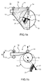
- the Figures 1a and 1b represent a diagram of a first embodiment of a deployable structure 10 according to the invention.
- the deployable structure 10 comprises a frame 11 comprising a first point 12 and a second point 13 facing each other and a third point 14. It comprises a storage roller 15 rotatable about a Z axis and a meter. Ribbon 16 adapted to pass from a configuration wrapped around the Z axis in the storage roll 15 to an expanded configuration along an axis X substantially perpendicular to the Z axis, the first and second points 12, 13 forming a double support with the tape measure 16 so as to maintain the tape measure 16 in deployed configuration.
- the third point 14 is able to form a simple support with the tape measure 16, the storage roll 15 is movable relative to the third point 14 and the storage roll 15 is pressed against the third point 14 of to guide the deployment of the tape measure 16.
- the three points 12, 13, 14, forming supports on the tape measure 16, allow a controlled orientation of the deployment of the tape measure 16.
- the points 12 and 13 allow in addition a correct unwinding of the tape measure 16.
- the support formed by the point 14 on the tape measure 16 is a point contact but can be considered in a wider sense the point 14 as a longitudinal support and in this case, this support can also form a longitudinal contact along an axis substantially perpendicular to the X axis, along the entire width of the tape measure 16 or only a part of the width of the tape measure 16. Without this contact, the tape measure could unfold in an uncontrolled manner according to any axis.
- Point 14 makes it possible to control the deployment of the tape measure thanks to a more or less resistant resistance depending on the type of regulation chosen (hybrid or electric).
- the contact is advantageously positioned near the deployed portion of the tape measure 16, to allow embedding and contribute to the maintenance of the tape measure 16 in its coiled portion.
- the points 12, 13, 14 may consist of a single support or a roller to limit friction during deployment or folding phases.
- the deployable structure 10 may comprise a guide lever 17 comprising two ends 18, 19, a first of the two ends 18 of the guide lever 17 being pivotally connected relative to the frame 11, a second of the two ends 19 being integral with the center of the guide roller 15. More specifically, the guide lever 17 is in contact with the frame 11 at its end 18 and in contact with the storage roller 15 at its end 19 which also forms contact with the frame 11 in the wound position of the tape measure, which makes it possible to prevent unwinding of the tape measure 16.
- the deployable structure 10 also comprises an elastic element 21 placed between the guide lever 17 and the frame 11, intended to push the guide lever 17 so as to press the storage roller 15 against the third point 14.
- the thrust of the elastic element 21 on the guide lever 17 is in a direction having a component along an axis Y, passing through the centers of 14 and 15 and, if possible, substantially perpendicular to the X and Z axes.
- the axis 18 may be positioned differently on the frame 11. Its position in deployed configuration may be preferably substantially parallel to that of the force so that its influence on the elastic element 21 is negligible, as shown in FIG. figure 1b .
- the elastic element 21 pushes the guide lever 17 towards the third point 14.
- the guide lever 17 and the elastic element 21 may be replaced by any other element ensuring the plating of the storage roll 15 against the third point 14.
- the figure 2 represents a diagram, in section in the plane perpendicular to the Z axis, of the first embodiment of the deployable structure 10 according to the invention, the tape measure 16 in partially deployed configuration. All elements of the figure 2 are identical to those of the figure 1a .
- the guide lever 17 is first detached relative to the frame 11 at the end 19 by means of a clearing system.
- the storage roll 15 comes then position itself in pressure against the third point 14 under the action of the elastic element 21.
- An engine or other deployment speed control system makes it possible to control the unwinding of the tape measure 16 around the storage roll 15, thus reducing the diameter of the storage roll 15 as the tape measure 16 becomes deploys.
- the end 18 of the guide lever being pivotally connected to the frame 11 and the end 19 of the guide lever 17 being equipped with a rotation guide of the storage roller 15, the guide lever 17 will push the roller of storage 15 to the third point 14. This thrust is favored by the presence of the elastic element 21.
- the tape measure 16 is in a partially deployed configuration. Its output is linear between the first and second points 12, 13.
- the diameter of the tape measure 16 is therefore less than that of the tape measure 16 in wound configuration.
- the storage roller 15 is always held pressed against the third point 14. It is important that the storage roller is well maintained. Indeed, if it was poorly maintained, there would be a slip between the different layers of the tape measure 16, which could lead to degradations of solar cells positioned on these layers.
- the adherent element may for example be an adhesive tape, a notched tape or a tape. Velcro tape.
- the three points 12, 13, 14 allow a good embedding of the deployable structure 10, and therefore a good rigidity of the structure, in all deployment configurations of the tape measure 16, that is to say in wound position, in fully or partially deployed position.
- the Figures 3a, 3b, 3c represent different possible configurations for the positioning of the supports on the tape measure 16.
- the points 12 and 13 can be opposite each other, as shown in FIG. figure 3a , and thus form a double support on both sides of the tape measure 16.
- the support formed by the point 13, instead of being applied vis-à-vis the point 12, can be divided into two supports at two points 13a and 13b, always in the same plane perpendicular to the axis of deployment of the 16.
- the two points 13a and 13b are then positioned at the end on the tape measure 16 in its width.
- the three points 12, 13a, 13b can press on the outer face or on the inside face of the tape measure 16, as shown in FIG. figure 3b .
- points 13a and 13b may be positioned to each form a support at the end of the arcuate section.
- the support 12, meanwhile, can be oriented along the Y axis, but it can also be shifted with respect to the Y axis.
- the figure 4 represents a diagram, in section in a plane perpendicular to the Z axis, of a second embodiment of a deployable structure 20 according to the invention, the tape measure 16 in wound configuration.
- the figure 5 represents a diagram, in section in a plane perpendicular to the Z axis, of the second embodiment of the deployable structure 20 according to the invention, the tape measure in deployed configuration. All the elements of the deployable structure 20 shown on the figure 5 are identical to those of the deployable structure 20 shown in FIG. figure 4 .
- the deployed structure 20 shown on the figure 4 comprises a frame 11 comprising the first point 12 and the second point 13 vis-à-vis and the third point 14. It comprises the storage roller 15 rotatable about the Z axis and the tape measure 16 adapted to passing from a configuration wrapped around the Z axis in the storage roll 15 to an X-axis deployed configuration, the first and second points 12, 13 forming a double support with the tape measure 16 so as to maintain the tape measure 16 in deployed configuration.
- the third point 14 is able to form a simple support with the tape measure 16, the storage roll 15 is movable relative to the third point 14 and the storage roll 15 is pressed against the third point 14 so as to guide the deployment of the tape measure 16.
- the frame 11 comprises a guiding device 22 and a base 23.
- the first 12, second 13 and third 14 points are integral with the guiding device 22.
- the guiding device 22 is hinged relative to the base 23, preferably around the third point 14, and rotatable about an axis parallel to the Z axis between a closed position and an open position and vice versa.
- the open position of the guiding device makes it possible to orient the deployment of the tape measure 16.
- This configuration makes it possible to have a reduced volume of the deployable structure 20 in the stored position.
- the guiding device 22 can be stored under the storage roll 15.
- the deployable structure 20 may further comprise a cam 24 positioned on the storage roll 15.
- the guiding device 22 comprises a roller 25 intended to be guided so as to control the rotation of the guiding device 22.
- the cam 24 can be a grooved cam.
- the guiding device 22 comprises a roller 25 intended to be housed in the groove so as to control the rotation of the guiding device 22 while resting on the storage roller 15.
- the deployable structure 20 further comprises a lever 17 and a resilient member 21.
- the first end 18 of the guide lever 17 being pivotally connected relative to the base 23, the second end 19 is integral with the center of the guide roller 15.
- the elastic element 21 is arranged between the guide lever 17 and the base 23, and is intended to push the guide lever 17 so as to press the storage roller 15 against the third point 14, as explained previously for the deployable structure 10.
- the deployable structure comprises a holding system 19 of the guide lever 17 and the guide device 22 in wound configuration for simultaneously releasing the guide lever 17 and the guide device 22 when the tape measure 16 passes from the wrapped configuration to the deployed configuration.
- the lever 17 and the guiding device 22 are simultaneously released by means of a stacking system and then when the unwinding of the measuring tape 16 is initiated by means of a motor or any other regulation system of speed, the tape measure being self-propelled.
- the guide lever 17 is firstly detached relative to the frame 11 at the end by means of a detachment system.
- the guide roller 15 then comes to be positioned in pressure against the third point 14 under the action of the elastic element 21.
- the roller 25 housed in the groove moves in the groove following the profile of the grooved cam 24.
- the guide device 22 is articulated around the third point 14, it leaves the stored position as the deployment unfolds.
- the deployment of the hinged guide device 22 is thus controlled.
- This configuration makes it possible to ensure good rigidity of the structure, and in particular of the tape measure 16, during the entire deployment of the tape measure 16 while limiting the bulk of the deployable structure 20.
- the roller 25 has controlled the opening of the guiding device 22 which is in the deployed position.
- the tape measure 16 is also in the deployed position.
- the cam 24 may comprise a non-return element 26, intended to prevent the rotation of the guiding device 22 towards the closed position.
- the non-return element 26 is intended to obstruct the groove so as to prevent the rotation of the guiding device 22 towards the closed position.
- the deployable structure 20 is in the stored position only at launch of the satellite. Once in orbit, it deploys the deployable structure 20, and it is sometimes necessary to partially fold. In this case, it is not desired a total folding, and therefore it is not desirable that the guide device 22 is controlled to its closed position.
- the non-return element 26 blocks the roller 25 in the groove and thus prevents the return to the closed position of the guiding system 22 and thus of the deployable structure 20.
- the invention is compatible with the use of a single tape measure but also a tape measure mounted in opposition.
- the figure 6 represents a diagram, in section in a plane perpendicular to the Z axis, of a third embodiment of a deployable structure 40 according to the invention, the tape measure 16 being mounted in opposition and in partially deployed configuration. All the elements of the deployable structure 40 shown on the figure 6 are identical to those of the deployable structure 30 shown on the figure 5 , the only difference residing in the fact that the tape measure 16 is mounted in opposition.
- the tape measure 16 has two ends 27, 28, a first end 27 of the tape measure 16 is attached to the storage roll 15 and a second end 28 of the tape measure 16 is attached to the pedestal 23.
- FIGs 7, 8, 9 represent a diagram, in section in a plane perpendicular to the Z axis, of a fourth embodiment of a deployable structure 50 according to the invention, the tape measure 16 having an end 28 fixed to the base 23, each of Figures corresponding to a different deployment configuration.
- All the elements of the deployable structure 50 shown on the Figures 7, 8, 9 are identical to those of the deployable structure 40 shown on the figure 6 , the grooved cam being here replaced by a direct support 44 on the storage roller 15.
- the tape measure 16 and the guiding device 22 are in the stored position.
- the guide lever 17 has its end 19 in contact with both the center of the storage roll 15 and the guide device 22.
- the deployable structure 50 is in a partially deployed configuration.
- the end 19 of the guide lever 17 has been detached, thereby releasing the guiding device 22 and allowing the elastic member 21 to push the storage roller 15 towards the third point 14.
- the guide device 22 unfolds. While unfolding, the tape measure 16 has a diameter that decreases. Conversely, during a partial winding phase, the tape measure 16 has its diameter which increases. Despite its progressive diameter, the tape measure 16 is permanently pressed against the third point 14, which contributes to a very good stability and a high stiffness to the embedding whatever the deployed length of ribbon and even if the tape measure 16 is not locked on its final position embedding, that is to say fully deployed.
- Another major advantage lies in the compactness of the deployable structure in stored position since the space dedicated to deployable structures under the casing of a launcher is limited.
- the deployable structures described in the context of the invention have a simplicity of assembly and ease of implementation.
- the invention can be applied to hybrid tape meters, consisting of a first driving structure (for example carbon fiber) which allows the deployment of the tape measure, and a regulating part (thermoelastic or a material having viscoelastic properties which limit the speed of deployment under the effect of the internal stress on the material or a material having a transformation temperature significantly lower than that of the main ribbon) which favors or limits the deployment as a function of the temperature which is applied.
- a first driving structure for example carbon fiber
- a regulating part thermoelastic or a material having viscoelastic properties which limit the speed of deployment under the effect of the internal stress on the material or a material having a transformation temperature significantly lower than that of the main ribbon
- the figure 10 represents a satellite 100 comprising at least one deployment device 61 equipped with a flexible membrane 60 and at least 2 deployable structures according to the invention.
- the deployable structure 61 further comprises a deployable articulated mast 110 attached to a platform of the satellite 100 via, for example, one or more engines rotating drive.
- the flexible membrane 60 is fully deployed.
- the satellite 100 comprises a second flexible membrane 60.
- the two deployment devices 61 are positioned on either side of the satellite 100.
- the deployment device 61 can be positioned in a T-shape with respect to the satellite 100 (configuration shown at the top of the figure 10 ), that is to say that its longitudinal main direction is perpendicular to the articulated mast 110.
- the deployment device can also be positioned in the form of I (configuration shown at the bottom of the figure 10 ), relative to the satellite 100, that is to say that its longitudinal main direction is in the extension of the articulated mast 110.
- the deployable structure according to the invention is used for only one deployment. Nevertheless, new mission needs appear. Including the transfer or towing of satellite from a low orbit to a high orbit. During the docking, for the control of the transfer vehicle, it takes the least possible inertia, that is to say that the presence of deployable structures of large dimensions is not favorable. It must also avoid any interference with satellites that we seek to dock. As a result, it is preferable to wind up the deployable structures. When the satellite is hooked, we can deploy the structure again.
Abstract
La présente invention concerne une structure déployable (10, 20, 40, 50) comprenant : ¢ un bâti (11) comprenant un premier point (12) et un deuxième point (13) en vis-à-vis et un troisième point (14), ¢ un rouleau de stockage (15) mobile en rotation autour d'un axe Z, ¢ un mètre-ruban (16) apte à passer d'une configuration enroulée autour de l'axe Z dans le rouleau de stockage (15) à une configuration déployée selon un axe X sensiblement perpendiculaire à l'axe Z, les premier et deuxième points (12, 13) formant un appui double avec le mètre-ruban (16) de façon à maintenir le mètre-ruban (16) en configuration déployée. Selon l'invention, le troisième point (14) est apte à former un appui simple avec le mètre-ruban (16), le rouleau de stockage (15) est mobile par rapport au troisième point (14) et le rouleau de stockage (15) est plaqué contre le troisième point (14) de manière à guider le déploiement du mètre-ruban (16).The present invention relates to a deployable structure (10, 20, 40, 50) comprising: ¢ a frame (11) comprising a first point (12) and a second point (13) facing each other and a third point (14), ¢ a storage roller (15) rotatable around a Z axis, ¢ a measuring tape (16) adapted to pass from a configuration wound around the Z axis in the storage roll (15) to a configuration deployed along an X axis substantially perpendicular to the Z axis, the first and second points (12, 13) forming a double support with the measuring tape (16) so as to maintain the measuring tape (16) in the deployed configuration. According to the invention, the third point (14) is able to form a simple support with the measuring tape (16), the storage roller (15) is movable relative to the third point (14) and the storage roller ( 15) is pressed against the third point (14) so as to guide the deployment of the measuring tape (16).
Description
La présente invention concerne une structure déployable escamotable à mètre-ruban pour une structure flexible, enroulable et déployable. Elle s'applique notamment au domaine des équipements spatiaux qui doivent être déployés en orbite et plus particulièrement aux équipements spatiaux pour satellites, tels que des antennes, des générateurs solaires, des écrans thermiques, des baffles ou des télescopes.The present invention relates to a retractable expandable structure with a tape measure for a flexible structure, rollable and deployable. It applies in particular to the field of space equipment that must be deployed in orbit and more particularly to space equipment for satellites, such as antennas, solar generators, heat shields, baffles or telescopes.
Les structures déployables dans l'espace, de type générateur solaire par exemple, sont généralement constituées de panneaux rigides articulés entre eux, ces panneaux étant, en position stockée, empilés les uns au-dessus des autres. Ces structures ont l'avantage d'avoir une cinématique maîtrisée mais présentent le désavantage d'une masse surfacique et d'une inertie importantes. En outre, les structures rigides occupent, en position stockée, un encombrement important sous la coiffe d'un lanceur. L'espace alloué aux structures déployables, sous la coiffe d'un lanceur, étant limité, il est important de réduire l'encombrement de ces structures déployables lorsqu'elles sont en position stockée de façon à en optimiser la surface en position déployée.The space-deployable structures, of the solar generator type for example, generally consist of rigid panels hinged together, these panels being, in the stored position, stacked one above the other. These structures have the advantage of having a controlled kinematics but have the disadvantage of a large surface mass and inertia. In addition, the rigid structures occupy, in the stored position, a large space under the cap of a launcher. The space allocated to the deployable structures, under the cap of a launcher, being limited, it is important to reduce the bulk of these deployable structures when they are in the stored position so as to optimize the surface in the deployed position.
Il existe des structures planes flexibles déployables comportant une toile flexible et des mètres-ruban (aussi connus dans la littérature anglo-saxonne sous le terme tape-spring) fixés sur un même plan de la toile. En position stockée, la toile et les mètres-ruban sont enroulés autour d'un mandrin. Le déploiement de la structure plane flexible est assuré de manière autonome par le déroulement spontané des mètres-ruban lorsque le mandrin est libre en rotation.There are deployable flexible flat structures comprising a flexible fabric and tape measures (also known in the Anglo-Saxon literature as tape-spring) fixed on the same plane of the canvas. In the stored position, the fabric and the tape measures are wrapped around a mandrel. The deployment of the flexible flat structure is autonomously ensured by the spontaneous unwinding of the tape-meters when the mandrel is free to rotate.
En effet, les mètres-ruban sont connus dans le domaine spatial comme étant des rubans flexibles ayant une section en arc de cercle dont le rayon de courbure est convexe sur une première face et concave sur une deuxième face, ces rubans étant aptes à passer de l'état enroulé à l'état déroulé essentiellement grâce à leur énergie élastique propre. Il existe différents types de ruban ayant des propriétés propres. Les rubans monostables possèdent une position naturelle déployée et nécessitent un maintien en position stockée. Les mètres-ruban monostables ont donc une tendance naturelle à se déployer pour se retrouver dans leur état déroulé. Le déploiement des rubans monostables est souvent anarchique et incontrôlé. Les rubans bistables possèdent deux positions naturelles (position stockée et position déployée) et ne nécessitent pas de maintien en position stockée lorsque la section est totalement applatie. Leur déploiement est linéaire et contrôlé. Cependant, dans tous les cas, lorsque le déploiement est déclenché, celui-ci peut être violent et générateur de chocs, c'est-à-dire que tout le mètre-ruban peut avoir tendance à se remettre droit simultanément, sur toute sa longueur, ce qui pose un risque d'endommagement des éléments environnants ou des éléments fixés sur le mètre-ruban tels qu'une membrane flexible, un instrument, une antenne... Les mètres-ruban classiques peuvent ainsi présenter des difficultés en termes de contrôle de leur déploiement. Afin de réguler la vitesse de déploiement de ce type de structure, plusieurs méthodes peuvent être utilisées. On peut citer par exemple une régulation par motoréducteur électrique comme décrit dans la demande de brevet
En outre, les mètres-ruban n'ont pas la même raideur suivant l'axe de contrainte. Un effort F appliqué sur la face convexe du mètre-ruban va avoir tendance à faire fléchir le mètre-ruban alors que le même effort appliqué sur la face concave n'aura aucun effet, ce qui pose un problème d'instabilité de la structure flexible dans son état déployé. Pour résoudre ce problème de stabilité de l'état déployé, il est alors nécessaire de maintenir le mètre-ruban en position déployée par un dispositif de maintien supplémentaire ou de sur-dimensionner le mètre-ruban pour qu'il reste stable sous les efforts orbitaux, quels que soient leurs sens d'application.In addition, the tape-meters do not have the same stiffness along the axis of stress. A force F applied on the convex face of the tape measure will have a tendency to bend the tape measure while the same force applied on the concave face will have no effect, which poses a problem of instability of the flexible structure in its unfolded state. To solve this problem of stability of the deployed state, it is then necessary to maintain the tape measure in the extended position by an additional holding device or to oversize the tape measure so that it remains stable under the orbital forces. whatever their application
Ainsi, en configuration stockée, le mètre-ruban doit être le plus compact possible, c'est-à-dire avoir un rayon d'enroulement le plus faible possible. Ce paramètre est donné par les caractéristiques physiques du ruban, généralement, le rayon d'enroulement est sensiblement égal à celui de leur rayon de courbure. Dans le cas d'un ruban composite, il peut être modifié en changeant l'empilage des plis et/ou le sens des fibres. En configuration déployée, la meilleure rigidité possible est recherchée, ce qui signifie une section la plus grande et la plus fermée possible associée à un encastrement de l'extrémité du mètre-ruban le plus important possible. Généralement, le déploiement du mètre-ruban est obtenu par déroulement du mètre-ruban autour d'un mandrin. Pendant le déploiement, le mètre-ruban a une rigidité dégradée du fait de la souplesse naturelle du mètre-ruban dans sa zone d'enroulement. La rigidité optimale est obtenue en fin de déploiement, quand on remplace la zone d'enroulement par un encastrement réel. Néanmoins, il est parfois souhaitable que la structure déployable soit opérationnelle dans toutes les phases de déploiement du mètre-ruban, c'est-à-dire en configuration de déploiement total ou partiel. Dans le cas d'une structure déployable ré-enroulable, il est nécessaire de créer un encastrement à l'ancrage du mètre-ruban permettant de garantir une rigidité compatible du besoin. Pour ce faire, on utilise généralement une rampe de guidage équipée de galets permettant d'obtenir simultanément l'extraction du mètre-ruban avec un bon encastrement. Cette solution est compatible du besoin mais pose différents problèmes, à savoir un risque d'arc-boutement ou déroulement intempestif du mètre-ruban si on veut utiliser l'énergie emmagasinée du mètre-ruban, une cinématique aléatoire de l'extrémité du ruban et un volume conséquent souvent incompatible du volume alloué au stockage.Thus, in stored configuration, the tape measure must be as compact as possible, that is to say have a winding radius as low as possible. This parameter is given by the physical characteristics of the ribbon, generally, the winding radius is substantially equal to that of their radius of curvature. In the case of a composite tape, it can be modified by changing the stack of folds and / or the direction of the fibers. In the deployed configuration, the best possible rigidity is sought, which means a larger and more closed section possible associated with embedding the end of the tape-meter as much as possible. Generally, the deployment of the tape measure is obtained by unfolding the tape measure around a mandrel. During deployment, the tape measure has a degraded rigidity due to the natural flexibility of the tape measure in its winding area. The optimal rigidity is obtained at the end of deployment, when the winding area is replaced by a real embedding. Nevertheless, it is sometimes desirable that the deployable structure be operational in all phases of deployment of the tape measure, that is to say in total or partial deployment configuration. In the case of a re-rollable deployable structure, it is necessary to create a recess to the anchoring of the tape measure to ensure a compatible rigidity of the need. To do this, it is generally used a guide rail equipped with rollers for simultaneously obtaining the extraction of the tape measure with a good embedding. This solution is compatible with the need but poses different problems, namely a risk of jamming or inadvertent unwinding of the tape measure if one wants to use the stored energy of the tape measure, a random kinematics of the end of the tape and a consequent volume often incompatible of the volume allocated to the storage.
Le diamètre du mètre-ruban évoluant tout au long du déploiement, il est nécessaire de réaliser plusieurs guidages complémentaires, en sortie de mètre-ruban, pour garantir le bon fonctionnement de l'ensemble de la structure déployable.The diameter of the measuring tape evolving throughout the deployment, it is necessary to perform several complementary guides, out of tape measure, to ensure the smooth operation of the entire deployable structure.
L'invention vise à pallier tout ou partie des problèmes cités plus haut en proposant une structure déployable escamotable pour une structure flexible, enroulable et déployable, présentant l'avantage d'être peu encombrante, simple à réaliser, présentant une optimisation du volume de la structure déployable lorsqu'elle est stockée sous la coiffe d'un lanceur, permettant une orientation maîtrisée du déploiement, un bon guidage du mètre-ruban malgré son diamètre évolutif et une capacité de reploiement et permettant une rigidité et une stabilité de la structure lorsqu'elle est déployée.The invention aims to overcome all or part of the problems mentioned above by providing a retractable deployable structure for a flexible structure, rollable and deployable, having the advantage of being compact, simple to perform, having an optimization of the volume of the deployable structure when stored under the cap of a launcher, allowing a controlled orientation of the deployment, a good guidance of the tape measure despite its scalable diameter and a folding capacity and allowing rigidity and stability of the structure when she is deployed.
A cet effet, l'invention a pour objet une structure déployable comprenant :
- un bâti comprenant un premier point et un deuxième point en vis-à-vis et un troisième point,
- un rouleau de stockage mobile en rotation autour d'un axe Z,
- un mètre-ruban apte à passer d'une configuration enroulée autour de l'axe Z dans le rouleau de stockage à une configuration déployée selon un axe X sensiblement perpendiculaire à l'axe Z, les premier et deuxième points formant un appui double avec le mètre-ruban de façon à maintenir le mètre-ruban en configuration déployée,
- un levier de
guidage 17 comprenant deuxextrémités extrémités 18 étant en liaison pivot par rapport aubâti 11, une seconde des deuxextrémités 19 étant solidaire du centre du rouleau deguidage 15, - un élément élastique 21 disposé entre le levier de
guidage 17 et lebâti 11, destiné à pousser le levier deguidage 17 de manière à plaquer le rouleau destockage 15 contre letroisième point 14.
- a frame comprising a first point and a second point vis-à-vis and a third point,
- a storage roller movable around a Z axis,
- a tape measure capable of passing from a configuration wound around the Z axis in the storage roll to a configuration deployed along an axis X substantially perpendicular to the Z axis, the first and second points forming a double support with the tape measure so as to maintain the tape measure in deployed configuration,
- a
guide lever 17 comprising twoends ends 18 being pivotally connected relative to theframe 11, a second of the twoends 19 being integral with the center of theguide roller 15, - an
elastic element 21 disposed between theguide lever 17 and theframe 11, intended to push theguide lever 17 so as to press thestorage roller 15 against thethird point 14.
Selon un mode de réalisation, le bâti comprend un dispositif de guidage et un socle, les premier, deuxième et troisième points sont solidaires du dispositif de guidage, le dispositif de guidage est articulé par rapport au socle, préférentiellement autour du troisième point, et mobile en rotation autour d'un axe parallèle à l'axe Z entre une position fermée et une position ouverte et inversement.According to one embodiment, the frame comprises a guide device and a base, the first, second and third points are integral with the guide device, the guide device is articulated relative to the base, preferably around the third point, and movable in rotation about an axis parallel to the Z axis between a closed position and an open position and vice versa.
Selon un autre mode de réalisation, la première des deux extrémités du levier de guidage est en liaison pivot par rapport au bâti, la seconde des deux extrémités est solidaire du centre du rouleau de guidage, et l'élément élastique est disposé entre le levier de guidage et le bâti, et destiné à pousser le levier de guidage de manière à plaquer le rouleau de stockage contre le troisième point.According to another embodiment, the first of the two ends of the guide lever is pivotally connected relative to the frame, the second of the two ends is integral with the center of the guide roller, and the elastic element is arranged between the lever of guide and the frame, and for pushing the guide lever so as to press the storage roller against the third point.
Selon un autre mode de réalisation, la première extrémité du levier de guidage est en liaison pivot par rapport au socle, la seconde extrémité est solidaire du centre du rouleau de guidage, l'élément élastique est disposé entre le levier de guidage et le socle, destiné à pousser le levier de guidage de manière à plaquer le rouleau de stockage contre le troisième point.According to another embodiment, the first end of the guide lever is pivotally connected relative to the base, the second end is integral with the center of the guide roller, the elastic element is disposed between the guide lever and the base, for pushing the guide lever so as to press the storage roller against the third point.
Selon un autre mode de réalisation, la structure déployable comprend en outre une came, par exemple à rainure, positionnée sur le rouleau de stockage et le dispositif de guidage comprend un galet destiné à être guidé de façon à piloter la rotation du dispositif de guidage pendant le déploiement du ruban.According to another embodiment, the deployable structure further comprises a cam, for example with a groove, positioned on the storage roll and the guiding device comprises a roller intended to be guided so as to control the rotation of the guiding device during the deployment of the ribbon.
Avantageusement, la structure déployable comprend un système de maintien du levier de guidage et du dispositif de guidage en configuration enroulée destiné à libérer simultanément le levier de guidage et le dispositif de guidage quand le mètre-ruban passe de la configuration enroulée à la configuration déployée.Advantageously, the deployable structure comprises a system for holding the guide lever and the guide device in a wound configuration for simultaneously releasing the guide lever and the guiding device when the measuring tape changes from the wound configuration to the deployed configuration.
Avantageusement, la came comprend un élément anti-retour, destiné à empêcher la rotation du dispositif de guidage vers la position fermée.Advantageously, the cam comprises a non-return element intended to prevent the rotation of the guiding device towards the closed position.
Selon un autre mode de réalisation, le mètre-ruban ayant deux extrémités, une première extrémité du mètre-ruban est fixée au rouleau de stockage et une seconde extrémité du mètre-ruban est fixée au socle.In another embodiment, the tape measure having two ends, a first end of the tape measure is attached to the storage roll and a second end of the tape measure is attached to the pedestal.
Avantageusement, la structure peut comprendre en outre un mât articulé déployable fixé sur une plateforme d'un satellite par l'intermédiaire d'un ou plusieurs moteurs d'entraînement en rotation.Advantageously, the structure may further comprise a deployable articulated mast fixed on a platform of a satellite via one or more rotary drive motors.
L'invention concerne aussi un satellite comprenant au moins une structure déployable.The invention also relates to a satellite comprising at least one deployable structure.
L'invention sera mieux comprise et d'autres avantages apparaîtront à la lecture de la description détaillée d'un mode de réalisation donné à titre d'exemple, description illustrée par le dessin joint dans lequel :
- les
figures 1a et 1b représentent chacune un schéma, en coupe dans un plan perpendiculaire à un axe Z, axe d'enroulement du mètre-ruban, d'un premier mode de réalisation d'une structure déployable selon l'invention, le mètre-ruban respectivement en configuration enroulée et partiellement déroulée, - la
figure 2 représente un schéma, en coupe dans le plan perpendiculaire à l'axe Z, du premier mode de réalisation de la structure déployable selon l'invention, le mètre-ruban en configuration partiellement déployée, - les
figures 3a, 3b, 3c représentent différentes configurations possibles pour le positionnement des appuis sur le mètre-ruban, - la
figure 4 représente un schéma, en coupe dans un plan perpendiculaire à l'axe Z, d'un deuxième mode de réalisation d'une structure déployable selon l'invention, le mètre-ruban en configuration enroulée, - la
figure 5 représente un schéma, en coupe dans un plan perpendiculaire à l'axe Z, du deuxième mode de réalisation d'une structure déployable selon l'invention, le mètre-ruban en configuration déployée, - la
figure 6 représente un schéma, en coupe dans un plan perpendiculaire à l'axe Z, d'un troisième mode de réalisation d'une structure déployable selon l'invention, le mètre-ruban en configuration partiellement déployée et ayant une extrémité fixée au socle, - les
figures 7, 8, 9 représentent un schéma, en coupe dans un plan perpendiculaire à l'axe Z, d'un quatrième mode de réalisation d'une structure déployable selon l'invention, le mètre-ruban ayant une extrémité fixée au socle, chacune des figures correspondant à une configuration de déploiement différente, - la
figure 10 représente schématiquement un satellite comprenant au moins une structure déployable selon l'invention.
- the
Figures 1a and 1b each represent a diagram, in section in a plane perpendicular to a Z axis, winding axis of the tape measure, of a first embodiment of a deployable structure according to the invention, the tape measure respectively in rolled configuration and partially unwound, - the
figure 2 represents a diagram, in section in the plane perpendicular to the Z axis, of the first embodiment of the deployable structure according to the invention, the tape measure in partially deployed configuration, - the
Figures 3a, 3b, 3c represent different possible configurations for the positioning of the supports on the tape measure, - the
figure 4 represents a diagram, in section in a plane perpendicular to the Z axis, of a second embodiment of a deployable structure according to the invention, the tape measure in wound configuration, - the
figure 5 represents a diagram, in section in a plane perpendicular to the Z axis, of the second embodiment of a deployable structure according to the invention, the tape measure in deployed configuration, - the
figure 6 represents a diagram, in section in a plane perpendicular to the Z axis, of a third embodiment of a deployable structure according to the invention, the tape measure in partially deployed configuration and having an end fixed to the base, - the
Figures 7, 8, 9 represent a diagram, in section in a plane perpendicular to the Z axis, of a fourth embodiment of a deployable structure according to the invention, the tape measure having an end fixed to the base, each of the figures corresponding to a different deployment configuration, - the
figure 10 schematically represents a satellite comprising at least one deployable structure according to the invention.
Par souci de clarté, les mêmes éléments porteront les mêmes repères dans les différentes figures.For the sake of clarity, the same elements will bear the same references in the different figures.
Les
Les trois points 12, 13, 14, en formant des appuis sur le mètre-ruban 16, permettent une orientation maîtrisée du déploiement du mètre-ruban 16. Les points 12 et 13 permettent en plus un déroulement correct du mètre-ruban 16.The three
L'appui formé par le point 14 sur le mètre-ruban 16 est un contact ponctuel mais on peut considérer dans un sens plus large le point 14 comme un appui longitudinal et dans ce cas, cet appui peut aussi former un contact longitudinal selon un axe sensiblement perpendiculaire à l'axe X, le long de toute la largeur du mètre-ruban 16 ou de seulement une partie de la largeur du mètre-ruban 16. En effet, sans ce contact, le mètre-ruban pourrait se déployer de manière incontrôlée selon un axe quelconque. Le point 14 permet de contrôler le déploiement du mètre-ruban grâce à un couple résistant plus ou moins important suivant le type de régulation choisi (hybride ou électrique). Le contact est avantageusement positionné à proximité de la partie déployée du mètre-ruban 16, afin de permettre un encastrement et contribuer au maintien du mètre-ruban 16 dans sa partie enroulée. Les points 12, 13, 14 peuvent êtres constitués d'un appui simple ou d'un galet afin de limiter les frottements lors de phases de déploiement ou de reploiement.The support formed by the
La structure déployable 10 peut comprendre un levier de guidage 17 comprenant deux extrémités 18, 19, une première des deux extrémités 18 du levier de guidage 17 étant en liaison pivot par rapport au bâti 11, une seconde des deux extrémités 19 étant solidaire du centre du rouleau de guidage 15. Plus précisément, le levier de guidage 17 est en contact avec le bâti 11 à son extrémité 18 et en contact avec le rouleau de stockage 15 à son extrémité 19 qui forme aussi un contact avec le bâti 11 en position enroulée du mètre-ruban, ce qui permet d'éviter le déroulement du mètre-ruban 16. La structure déployable 10 comprend aussi un élément élastique 21 disposé entre le levier de guidage 17 et le bâti 11, destiné à pousser le levier de guidage 17 de manière à plaquer le rouleau de stockage 15 contre le troisième point 14. La poussée de l'élément élastique 21 sur le levier de guidage 17 se fait dans une direction ayant une composante selon un axe Y, passant par les centres de 14 et 15 et, si possible, sensiblement perpendiculaire aux axes X et Z. Cependant, afin de contrer plus aisément les efforts du mètre-ruban 16 sur le rouleau 15 en configuration déployée, l'axe 18 peut être positionné différemment sur le bâti 11. Sa position en configuration déployée pourrait être préférentiellement sensiblement parallèle à celle de l'effort de manière à ce que son influence sur l'élément élastique 21 soit négligeable, comme représenté sur la
Comme le rouleau de stockage 15 est plaqué contre le troisième point 14, malgré le diamètre évolutif du mètre-ruban lors de son déploiement, l'appui simple formé par le point 14 est toujours présent, ce qui a l'avantage de guider le déploiement du mètre-ruban 16 de manière maîtrisée.Since the
La
Un moteur ou tout autre système de régulation de vitesse de déploiement permet de maîtriser le déroulement du mètre-ruban 16 autour du rouleau de stockage 15 entraînant la réduction du diamètre du rouleau de stockage 15 au fur et à mesure que le mètre-ruban 16 se déploie. L'extrémité 18 du levier de guidage étant en liaison pivot avec le bâti 11 et l'extrémité 19 du levier de guidage 17 étant équipée d'un guidage en rotation du rouleau de stockage 15, le levier de guidage 17 va pousser le rouleau de stockage 15 vers le troisième point 14. Cette poussée est favorisée par la présence de l'élément élastique 21. Comme représenté sur la
Il est par ailleurs possible, dans le souci d'avoir une bonne adhérence des couches entre elles, d'ajouter un élément adhérent sur le mètre-ruban 16. L'élément adhérent peut par exemple être une bande adhésive, une bande crantée ou une bande auto-agrippante.It is also possible, in order to have good adhesion between the layers, to add an adherent element on the
Les trois points 12, 13, 14 permettent un bon encastrement de la structure déployable 10, et donc une bonne rigidité de la structure, dans toutes les configurations de déploiement du mètre-ruban 16, c'est-à-dire en position enroulée, en position totalement ou partiellement déployée.The three
En fonction de l'orientation des efforts ou des moments en bout de mètre-ruban 16, il est possible de supprimer un des deux appuis 12 ou 13.Depending on the orientation of the forces or moments at the end of
Les
La
De même que la structure déployable 10 représentée sur la
Sur la
La structure déployable 20 peut comprendre en outre une came 24 positionnée sur le rouleau de stockage 15. Le dispositif de guidage 22 comprend un galet 25 destiné à être guidé de façon à piloter la rotation du dispositif de guidage 22. Par exemple, la came 24 peut être une came à rainure. Dans ce cas, le dispositif de guidage 22 comprend un galet 25 destiné à être logé dans la rainure de façon à piloter la rotation du dispositif de guidage 22 en prenant appui sur le rouleau de stockage 15. La structure déployable 20 comprend en outre un levier de guidage 17 et un élément élastique 21. La première extrémité 18 du levier de guidage 17 étant en liaison pivot par rapport au socle 23, la seconde extrémité 19 est solidaire du centre du rouleau de guidage 15. L'élément élastique 21 est disposé entre le levier de guidage 17 et le socle 23, et est destiné à pousser le levier de guidage 17 de manière à plaquer le rouleau de stockage 15 contre le troisième point 14, comme expliqué précédemment pour la structure déployable 10.The
Ainsi, on peut considérer que la structure déployable comprend un système de maintien 19 du levier de guidage 17 et du dispositif de guidage 22 en configuration enroulée destiné à libérer simultanément le levier de guidage 17 et le dispositif de guidage 22 quand le mètre-ruban 16 passe de la configuration enroulée à la configuration déployée. Quand on souhaite passer de la configuration enroulée (comme représentée sur la
Le galet 25 logé dans la rainure se déplace dans la rainure en suivant le profil de la came à rainure 24. Comme le dispositif de guidage 22 est articulé autour du troisième point 14, il sort de la position stockée au fur et à mesure du déploiement du mètre-ruban 16. Le déploiement du dispositif de guidage 22 articulé est ainsi maîtrisé. Cette configuration permet d'assurer une bonne rigidité de la structure, et notamment du mètre-ruban 16, pendant tout le déploiement du mètre-ruban 16 tout en limitant l'encombrement de la structure déployable 20. Le galet 25 a piloté l'ouverture du dispositif de guidage 22 qui est en position déployée. Le mètre-ruban 16 est lui aussi en position déployée.The
La came 24 peut comprendre un élément anti-retour 26, destiné à empêcher la rotation du dispositif de guidage 22 vers la position fermée. Dans l'exemple d'une came à rainure, l'élément anti-retour 26 est destiné à obstruer la rainure de façon à empêcher la rotation du dispositif de guidage 22 vers la position fermée. Généralement, la structure déployable 20 est en position stockée uniquement au lancement du satellite. Une fois en orbite, on procède au déploiement de la structure déployable 20, et il est parfois nécessaire de la reployer partiellement. Dans ce cas, on ne souhaite pas un reploiement total, et donc il n'est pas souhaitable que le dispositif de guidage 22 soit piloté vers sa position fermée. L'élément anti-retour 26 bloque le galet 25 dans la rainure et empêche ainsi le retour en position fermée du système de guidage 22 et donc de la structure déployable 20.The
L'invention est compatible de l'utilisation d'un mètre-ruban simple mais aussi d'un mètre-ruban monté en opposition. La
Les
L'invention peut s'appliquer aux mètres-ruban hybrides, constitués d'une première structure motrice (par exemple en fibre de carbone) qui permet le déploiement du mètre-ruban, et d'une partie régulatrice (thermoélastique ou en un matériau ayant des propriétés viscoélastiques qui limite la vitesse de déploiement sous l'effet de la contrainte interne au matériau ou en un matériau ayant une température de transformation notablement inférieure à celle du ruban principal) qui favorise ou limite le déploiement en fonction de la température qui lui est appliquée. En utilisant un phénomène naturel de changement de viscosité d'un matériau par la température une bonne fiabilité et une reproductibilité de régulation du déploiement sont garanties.The invention can be applied to hybrid tape meters, consisting of a first driving structure (for example carbon fiber) which allows the deployment of the tape measure, and a regulating part (thermoelastic or a material having viscoelastic properties which limit the speed of deployment under the effect of the internal stress on the material or a material having a transformation temperature significantly lower than that of the main ribbon) which favors or limits the deployment as a function of the temperature which is applied. By using a natural phenomenon of change of viscosity of a material by the temperature a good reliability and a reproducibility of regulation of the deployment are guaranteed.
On peut noter que dans le cas de l'utilisation de mètres-ruban hybrides, le reploiement est impossible par la simple force du mètre-ruban car le mètre-ruban n'est moteur que dans le sens de déploiement. Pour permettre un reploiement du mètre-ruban, il faut y adjoindre un motoréducteur électrique. De ce fait, si on souhaite un déploiement monocoup, il est possible d'avoir une régulation et/ou motorisation hybride ou électrique. Si des déploiements multiples du mètre-ruban sont à prévoir, la régulation et/ou motorisation devra alors être électrique. Et on peut prévoir un chauffage dans la zone des appuis 12, 13 et 14 par exemple.It should be noted that in the case of the use of hybrid tape meters, the folding is impossible by the simple force of the tape measure because the tape measure is only motor in the direction of deployment. To allow a folding of the tape measure, it is necessary to add an electric geared motor. Therefore, if one wishes a one-shot deployment, it is possible to have a regulation and / or hybrid or electric motorization. If multiple deployments of the tape measure are to be expected, the regulation and / or motorization will then be electrical. And one can provide a heating in the area of the
La
Généralement, en utilisation réelle, la structure déployable selon l'invention n'est utilisée que pour un seul déploiement. Néanmoins de nouveaux besoins de mission apparaissent. Notamment le transfert ou le remorquage de satellite d'une orbite basse vers une orbite haute. Lors de l'accostage, pour le pilotage du véhicule de transfert, il faut le moins d'inertie possible, c'est-à-dire que la présence de structures déployables de grandes dimensions n'est pas favorable. II faut éviter aussi toute interférence avec les satellites que l'on cherche à accoster. De ce fait, il est préférable d'enrouler les structures déployables. Quand le satellite est accroché, on peut de nouveau déployer la structure.Generally, in actual use, the deployable structure according to the invention is used for only one deployment. Nevertheless, new mission needs appear. Including the transfer or towing of satellite from a low orbit to a high orbit. During the docking, for the control of the transfer vehicle, it takes the least possible inertia, that is to say that the presence of deployable structures of large dimensions is not favorable. It must also avoid any interference with satellites that we seek to dock. As a result, it is preferable to wind up the deployable structures. When the satellite is hooked, we can deploy the structure again.
Claims (9)
Applications Claiming Priority (1)
| Application Number | Priority Date | Filing Date | Title |
|---|---|---|---|
| FR1402620A FR3028842A1 (en) | 2014-11-21 | 2014-11-21 | RETRACTABLE DEPLOYABLE STRUCTURE WITH METER-RIBBON |
Publications (2)
| Publication Number | Publication Date |
|---|---|
| EP3023333A1 true EP3023333A1 (en) | 2016-05-25 |
| EP3023333B1 EP3023333B1 (en) | 2017-02-22 |
Family
ID=52988090
Family Applications (1)
| Application Number | Title | Priority Date | Filing Date |
|---|---|---|---|
| EP15195097.9A Active EP3023333B1 (en) | 2014-11-21 | 2015-11-18 | Retractable and deployable structure with tape measure |
Country Status (6)
| Country | Link |
|---|---|
| US (1) | US9796485B2 (en) |
| EP (1) | EP3023333B1 (en) |
| JP (1) | JP6762705B2 (en) |
| CA (1) | CA2913018C (en) |
| ES (1) | ES2624262T3 (en) |
| FR (1) | FR3028842A1 (en) |
Cited By (2)
| Publication number | Priority date | Publication date | Assignee | Title |
|---|---|---|---|---|
| EP3640146A1 (en) * | 2018-10-18 | 2020-04-22 | Thales | Deployable device with tape measure |
| FR3110552A1 (en) * | 2020-05-20 | 2021-11-26 | Thales | Vehicle in orbit with roll-up and deployable membrane for attitude and orbit control |
Families Citing this family (6)
| Publication number | Priority date | Publication date | Assignee | Title |
|---|---|---|---|---|
| US10263316B2 (en) | 2013-09-06 | 2019-04-16 | MMA Design, LLC | Deployable reflectarray antenna structure |
| FR3048418B1 (en) * | 2016-03-02 | 2019-04-19 | Thales | DEVICE FOR DEPLOYING AND POINTING |
| KR102440495B1 (en) * | 2016-10-05 | 2022-09-07 | 현대자동차주식회사 | Speed bump assembly installed within vehicle |
| CN107539497A (en) * | 2017-09-01 | 2018-01-05 | 上海微小卫星工程中心 | A kind of three cell cube micro-nano satellite structures |
| FR3087426B1 (en) * | 2018-10-18 | 2022-03-11 | Thales Sa | DEPLOYABLE DEVICE WITH NON CONSTANT AREA TAPE MEASURE |
| CN113895097B (en) * | 2021-10-25 | 2023-06-23 | 福州大学 | Composite material thin shell plane folding and unfolding device and folding and unfolding method |
Citations (6)
| Publication number | Priority date | Publication date | Assignee | Title |
|---|---|---|---|---|
| FR803986A (en) | 1935-07-03 | 1936-10-13 | pin to fix the sheets before riveting | |
| FR1203300A (en) | 1958-09-16 | 1960-01-18 | Type of construction with bare-storey platforms for the development of individual light houses | |
| US3243132A (en) * | 1963-04-01 | 1966-03-29 | Dehavilland Aircraft Canada | Extensible retractable stem device |
| GB2298182A (en) * | 1995-02-21 | 1996-08-28 | Burt Will Comp | Telescopic Mast Assembly |
| FR2868094A1 (en) * | 2004-03-25 | 2005-09-30 | Paul Ducret | Automatic barrier system for e.g. car park, linearly deploys laminated steel band maintained on motorized wheel by pressure rollers, and fixed to axle that is adjusted by displacement in slot |
| US7856735B2 (en) | 2008-07-11 | 2010-12-28 | Thales | Measuring tape with thermal deployment and deployable structure comprising said measuring tape |
Family Cites Families (5)
| Publication number | Priority date | Publication date | Assignee | Title |
|---|---|---|---|---|
| US3434254A (en) * | 1965-10-04 | 1969-03-25 | Trw Inc | Deployable boom |
| US3589632A (en) * | 1969-04-30 | 1971-06-29 | Westinghouse Electric Corp | Self-forming-boom storing and deploying apparatus |
| US4117495A (en) * | 1977-03-01 | 1978-09-26 | Hochstein Peter A | Self-tuning deployable antenna |
| GB2202815B (en) * | 1987-03-30 | 1991-07-24 | Mantell Technical Services Lim | Load pushing apparatus |
| FR2998876B1 (en) | 2012-12-05 | 2015-07-17 | Thales Sa | DEVICE FOR DEPLOYING AND REPLOYING A FLEXIBLE STRUCTURE, FLEXIBLE DEPLOYABLE STRUCTURE AND SATELLITE PROVIDED WITH SUCH A DEVICE |
-
2014
- 2014-11-21 FR FR1402620A patent/FR3028842A1/en active Pending
-
2015
- 2015-11-18 ES ES15195097.9T patent/ES2624262T3/en active Active
- 2015-11-18 EP EP15195097.9A patent/EP3023333B1/en active Active
- 2015-11-18 US US14/945,273 patent/US9796485B2/en active Active
- 2015-11-20 JP JP2015227523A patent/JP6762705B2/en active Active
- 2015-11-20 CA CA2913018A patent/CA2913018C/en active Active
Patent Citations (6)
| Publication number | Priority date | Publication date | Assignee | Title |
|---|---|---|---|---|
| FR803986A (en) | 1935-07-03 | 1936-10-13 | pin to fix the sheets before riveting | |
| FR1203300A (en) | 1958-09-16 | 1960-01-18 | Type of construction with bare-storey platforms for the development of individual light houses | |
| US3243132A (en) * | 1963-04-01 | 1966-03-29 | Dehavilland Aircraft Canada | Extensible retractable stem device |
| GB2298182A (en) * | 1995-02-21 | 1996-08-28 | Burt Will Comp | Telescopic Mast Assembly |
| FR2868094A1 (en) * | 2004-03-25 | 2005-09-30 | Paul Ducret | Automatic barrier system for e.g. car park, linearly deploys laminated steel band maintained on motorized wheel by pressure rollers, and fixed to axle that is adjusted by displacement in slot |
| US7856735B2 (en) | 2008-07-11 | 2010-12-28 | Thales | Measuring tape with thermal deployment and deployable structure comprising said measuring tape |
Cited By (3)
| Publication number | Priority date | Publication date | Assignee | Title |
|---|---|---|---|---|
| EP3640146A1 (en) * | 2018-10-18 | 2020-04-22 | Thales | Deployable device with tape measure |
| FR3087425A1 (en) * | 2018-10-18 | 2020-04-24 | Thales | DEPLOYABLE TAPE MEASURING DEVICE |
| FR3110552A1 (en) * | 2020-05-20 | 2021-11-26 | Thales | Vehicle in orbit with roll-up and deployable membrane for attitude and orbit control |
Also Published As
| Publication number | Publication date |
|---|---|
| CA2913018C (en) | 2023-03-07 |
| CA2913018A1 (en) | 2016-05-21 |
| US20160144984A1 (en) | 2016-05-26 |
| ES2624262T3 (en) | 2017-07-13 |
| FR3028842A1 (en) | 2016-05-27 |
| JP2016120904A (en) | 2016-07-07 |
| EP3023333B1 (en) | 2017-02-22 |
| JP6762705B2 (en) | 2020-09-30 |
| US9796485B2 (en) | 2017-10-24 |
Similar Documents
| Publication | Publication Date | Title |
|---|---|---|
| EP3023333B1 (en) | Retractable and deployable structure with tape measure | |
| EP2977322B1 (en) | Method for retractable embedding of a tape measure for a deployable structure and deployable structure with tape measure | |
| EP2977323B1 (en) | Deployable structure with tape-spring | |
| EP2471714B1 (en) | Extendable planar solar generator | |
| EP2740669B1 (en) | Device for deploying and retracting a flexible structure, flexible deployable structure and satellite provided with such a device | |
| EP2143641B1 (en) | Tape measure with thermal unrolling and unrolling structure comprising such a tape measure | |
| EP3176095B1 (en) | Deployable structure comprising a set of solar generators, system for deploying such a deployable structure and satellite comprising such a system | |
| EP3640146B1 (en) | Deployable device with tape measure | |
| WO2009153454A2 (en) | Hinged folding structure | |
| EP3433173B1 (en) | Spacecraft | |
| EP2724945A2 (en) | Motorisation system for articulation with flexible roller tracks | |
| EP2520494B1 (en) | Device for protecting a multiple mirror optical instrument | |
| EP3795480B1 (en) | Deployable device | |
| EP2461065B1 (en) | Hinge device with a strand bundle in a shape memory material | |
| FR3015131A1 (en) | SEGMENTED STRUCTURE, IN PARTICULAR FOR A SATELLITE ANTENNA REFLECTOR, PROVIDED WITH AT LEAST ONE RIBBON DEPLOYMENT DEVICE | |
| FR2486493A1 (en) | IMPROVEMENTS IN SYSTEMS FOR FOLDING AND STABILIZING SOLAR PANELS | |
| EP4321702A1 (en) | Sun or weather protection device | |
| FR3110552A1 (en) | Vehicle in orbit with roll-up and deployable membrane for attitude and orbit control | |
| FR3098651A1 (en) | THREE-DIMENSIONAL DEPLOYMENT DEVICE | |
| FR3060536A1 (en) | SPACE ENGINE | |
| FR2711111A1 (en) | Spacecraft with solar sail and method for piloting such a craft | |
| FR2717207A1 (en) | Unfoldable carrying mast for raising loads |
Legal Events
| Date | Code | Title | Description |
|---|---|---|---|
| AK | Designated contracting states |
Kind code of ref document: A1 Designated state(s): AL AT BE BG CH CY CZ DE DK EE ES FI FR GB GR HR HU IE IS IT LI LT LU LV MC MK MT NL NO PL PT RO RS SE SI SK SM TR |
|
| AX | Request for extension of the european patent |
Extension state: BA ME |
|
| PUAI | Public reference made under article 153(3) epc to a published international application that has entered the european phase |
Free format text: ORIGINAL CODE: 0009012 |
|
| 17P | Request for examination filed |
Effective date: 20160704 |
|
| RBV | Designated contracting states (corrected) |
Designated state(s): AL AT BE BG CH CY CZ DE DK EE ES FI FR GB GR HR HU IE IS IT LI LT LU LV MC MK MT NL NO PL PT RO RS SE SI SK SM TR |
|
| RIC1 | Information provided on ipc code assigned before grant |
Ipc: B64G 1/44 20060101ALN20160726BHEP Ipc: B65H 75/36 20060101ALI20160726BHEP Ipc: B64G 1/66 20060101ALN20160726BHEP Ipc: B64G 1/22 20060101AFI20160726BHEP Ipc: B64G 1/50 20060101ALN20160726BHEP |
|
| GRAP | Despatch of communication of intention to grant a patent |
Free format text: ORIGINAL CODE: EPIDOSNIGR1 |
|
| INTG | Intention to grant announced |
Effective date: 20160912 |
|
| GRAS | Grant fee paid |
Free format text: ORIGINAL CODE: EPIDOSNIGR3 |
|
| GRAA | (expected) grant |
Free format text: ORIGINAL CODE: 0009210 |
|
| AK | Designated contracting states |
Kind code of ref document: B1 Designated state(s): AL AT BE BG CH CY CZ DE DK EE ES FI FR GB GR HR HU IE IS IT LI LT LU LV MC MK MT NL NO PL PT RO RS SE SI SK SM TR |
|
| REG | Reference to a national code |
Ref country code: GB Ref legal event code: FG4D Free format text: NOT ENGLISH |
|
| REG | Reference to a national code |
Ref country code: CH Ref legal event code: EP |
|
| REG | Reference to a national code |
Ref country code: AT Ref legal event code: REF Ref document number: 869064 Country of ref document: AT Kind code of ref document: T Effective date: 20170315 |
|
| REG | Reference to a national code |
Ref country code: IE Ref legal event code: FG4D Free format text: LANGUAGE OF EP DOCUMENT: FRENCH |
|
| REG | Reference to a national code |
Ref country code: CH Ref legal event code: NV Representative=s name: SERVOPATENT GMBH, CH |
|
| REG | Reference to a national code |
Ref country code: DE Ref legal event code: R096 Ref document number: 602015001564 Country of ref document: DE |
|
| REG | Reference to a national code |
Ref country code: NL Ref legal event code: FP |
|
| REG | Reference to a national code |
Ref country code: LT Ref legal event code: MG4D |
|
| REG | Reference to a national code |
Ref country code: ES Ref legal event code: FG2A Ref document number: 2624262 Country of ref document: ES Kind code of ref document: T3 Effective date: 20170713 |
|
| REG | Reference to a national code |
Ref country code: AT Ref legal event code: MK05 Ref document number: 869064 Country of ref document: AT Kind code of ref document: T Effective date: 20170222 |
|
| PG25 | Lapsed in a contracting state [announced via postgrant information from national office to epo] |
Ref country code: LT Free format text: LAPSE BECAUSE OF FAILURE TO SUBMIT A TRANSLATION OF THE DESCRIPTION OR TO PAY THE FEE WITHIN THE PRESCRIBED TIME-LIMIT Effective date: 20170222 Ref country code: NO Free format text: LAPSE BECAUSE OF FAILURE TO SUBMIT A TRANSLATION OF THE DESCRIPTION OR TO PAY THE FEE WITHIN THE PRESCRIBED TIME-LIMIT Effective date: 20170522 Ref country code: HR Free format text: LAPSE BECAUSE OF FAILURE TO SUBMIT A TRANSLATION OF THE DESCRIPTION OR TO PAY THE FEE WITHIN THE PRESCRIBED TIME-LIMIT Effective date: 20170222 Ref country code: GR Free format text: LAPSE BECAUSE OF FAILURE TO SUBMIT A TRANSLATION OF THE DESCRIPTION OR TO PAY THE FEE WITHIN THE PRESCRIBED TIME-LIMIT Effective date: 20170523 Ref country code: FI Free format text: LAPSE BECAUSE OF FAILURE TO SUBMIT A TRANSLATION OF THE DESCRIPTION OR TO PAY THE FEE WITHIN THE PRESCRIBED TIME-LIMIT Effective date: 20170222 |
|
| PG25 | Lapsed in a contracting state [announced via postgrant information from national office to epo] |
Ref country code: LV Free format text: LAPSE BECAUSE OF FAILURE TO SUBMIT A TRANSLATION OF THE DESCRIPTION OR TO PAY THE FEE WITHIN THE PRESCRIBED TIME-LIMIT Effective date: 20170222 Ref country code: PT Free format text: LAPSE BECAUSE OF FAILURE TO SUBMIT A TRANSLATION OF THE DESCRIPTION OR TO PAY THE FEE WITHIN THE PRESCRIBED TIME-LIMIT Effective date: 20170622 Ref country code: BG Free format text: LAPSE BECAUSE OF FAILURE TO SUBMIT A TRANSLATION OF THE DESCRIPTION OR TO PAY THE FEE WITHIN THE PRESCRIBED TIME-LIMIT Effective date: 20170522 Ref country code: AT Free format text: LAPSE BECAUSE OF FAILURE TO SUBMIT A TRANSLATION OF THE DESCRIPTION OR TO PAY THE FEE WITHIN THE PRESCRIBED TIME-LIMIT Effective date: 20170222 Ref country code: RS Free format text: LAPSE BECAUSE OF FAILURE TO SUBMIT A TRANSLATION OF THE DESCRIPTION OR TO PAY THE FEE WITHIN THE PRESCRIBED TIME-LIMIT Effective date: 20170222 Ref country code: SE Free format text: LAPSE BECAUSE OF FAILURE TO SUBMIT A TRANSLATION OF THE DESCRIPTION OR TO PAY THE FEE WITHIN THE PRESCRIBED TIME-LIMIT Effective date: 20170222 |
|
| REG | Reference to a national code |
Ref country code: FR Ref legal event code: PLFP Year of fee payment: 3 |
|
| PG25 | Lapsed in a contracting state [announced via postgrant information from national office to epo] |
Ref country code: RO Free format text: LAPSE BECAUSE OF FAILURE TO SUBMIT A TRANSLATION OF THE DESCRIPTION OR TO PAY THE FEE WITHIN THE PRESCRIBED TIME-LIMIT Effective date: 20170222 Ref country code: EE Free format text: LAPSE BECAUSE OF FAILURE TO SUBMIT A TRANSLATION OF THE DESCRIPTION OR TO PAY THE FEE WITHIN THE PRESCRIBED TIME-LIMIT Effective date: 20170222 Ref country code: CZ Free format text: LAPSE BECAUSE OF FAILURE TO SUBMIT A TRANSLATION OF THE DESCRIPTION OR TO PAY THE FEE WITHIN THE PRESCRIBED TIME-LIMIT Effective date: 20170222 Ref country code: SK Free format text: LAPSE BECAUSE OF FAILURE TO SUBMIT A TRANSLATION OF THE DESCRIPTION OR TO PAY THE FEE WITHIN THE PRESCRIBED TIME-LIMIT Effective date: 20170222 |
|
| REG | Reference to a national code |
Ref country code: DE Ref legal event code: R097 Ref document number: 602015001564 Country of ref document: DE |
|
| PG25 | Lapsed in a contracting state [announced via postgrant information from national office to epo] |
Ref country code: SM Free format text: LAPSE BECAUSE OF FAILURE TO SUBMIT A TRANSLATION OF THE DESCRIPTION OR TO PAY THE FEE WITHIN THE PRESCRIBED TIME-LIMIT Effective date: 20170222 Ref country code: DK Free format text: LAPSE BECAUSE OF FAILURE TO SUBMIT A TRANSLATION OF THE DESCRIPTION OR TO PAY THE FEE WITHIN THE PRESCRIBED TIME-LIMIT Effective date: 20170222 Ref country code: PL Free format text: LAPSE BECAUSE OF FAILURE TO SUBMIT A TRANSLATION OF THE DESCRIPTION OR TO PAY THE FEE WITHIN THE PRESCRIBED TIME-LIMIT Effective date: 20170222 |
|
| PLBE | No opposition filed within time limit |
Free format text: ORIGINAL CODE: 0009261 |
|
| STAA | Information on the status of an ep patent application or granted ep patent |
Free format text: STATUS: NO OPPOSITION FILED WITHIN TIME LIMIT |
|
| 26N | No opposition filed |
Effective date: 20171123 |
|
| PG25 | Lapsed in a contracting state [announced via postgrant information from national office to epo] |
Ref country code: SI Free format text: LAPSE BECAUSE OF FAILURE TO SUBMIT A TRANSLATION OF THE DESCRIPTION OR TO PAY THE FEE WITHIN THE PRESCRIBED TIME-LIMIT Effective date: 20170222 |
|
| PG25 | Lapsed in a contracting state [announced via postgrant information from national office to epo] |
Ref country code: MC Free format text: LAPSE BECAUSE OF FAILURE TO SUBMIT A TRANSLATION OF THE DESCRIPTION OR TO PAY THE FEE WITHIN THE PRESCRIBED TIME-LIMIT Effective date: 20170222 |
|
| PG25 | Lapsed in a contracting state [announced via postgrant information from national office to epo] |
Ref country code: LU Free format text: LAPSE BECAUSE OF NON-PAYMENT OF DUE FEES Effective date: 20171118 |
|
| REG | Reference to a national code |
Ref country code: BE Ref legal event code: MM Effective date: 20171130 |
|
| REG | Reference to a national code |
Ref country code: IE Ref legal event code: MM4A |
|
| PG25 | Lapsed in a contracting state [announced via postgrant information from national office to epo] |
Ref country code: MT Free format text: LAPSE BECAUSE OF FAILURE TO SUBMIT A TRANSLATION OF THE DESCRIPTION OR TO PAY THE FEE WITHIN THE PRESCRIBED TIME-LIMIT Effective date: 20170222 |
|
| REG | Reference to a national code |
Ref country code: FR Ref legal event code: PLFP Year of fee payment: 4 |
|
| PG25 | Lapsed in a contracting state [announced via postgrant information from national office to epo] |
Ref country code: IE Free format text: LAPSE BECAUSE OF NON-PAYMENT OF DUE FEES Effective date: 20171118 |
|
| PG25 | Lapsed in a contracting state [announced via postgrant information from national office to epo] |
Ref country code: BE Free format text: LAPSE BECAUSE OF NON-PAYMENT OF DUE FEES Effective date: 20171130 |
|
| PG25 | Lapsed in a contracting state [announced via postgrant information from national office to epo] |
Ref country code: HU Free format text: LAPSE BECAUSE OF FAILURE TO SUBMIT A TRANSLATION OF THE DESCRIPTION OR TO PAY THE FEE WITHIN THE PRESCRIBED TIME-LIMIT; INVALID AB INITIO Effective date: 20151118 |
|
| PG25 | Lapsed in a contracting state [announced via postgrant information from national office to epo] |
Ref country code: CY Free format text: LAPSE BECAUSE OF FAILURE TO SUBMIT A TRANSLATION OF THE DESCRIPTION OR TO PAY THE FEE WITHIN THE PRESCRIBED TIME-LIMIT Effective date: 20170222 |
|
| PG25 | Lapsed in a contracting state [announced via postgrant information from national office to epo] |
Ref country code: MK Free format text: LAPSE BECAUSE OF FAILURE TO SUBMIT A TRANSLATION OF THE DESCRIPTION OR TO PAY THE FEE WITHIN THE PRESCRIBED TIME-LIMIT Effective date: 20170222 |
|
| PG25 | Lapsed in a contracting state [announced via postgrant information from national office to epo] |
Ref country code: TR Free format text: LAPSE BECAUSE OF FAILURE TO SUBMIT A TRANSLATION OF THE DESCRIPTION OR TO PAY THE FEE WITHIN THE PRESCRIBED TIME-LIMIT Effective date: 20170222 |
|
| REG | Reference to a national code |
Ref country code: CH Ref legal event code: PCAR Free format text: NEW ADDRESS: WANNERSTRASSE 9/1, 8045 ZUERICH (CH) |
|
| PG25 | Lapsed in a contracting state [announced via postgrant information from national office to epo] |
Ref country code: AL Free format text: LAPSE BECAUSE OF FAILURE TO SUBMIT A TRANSLATION OF THE DESCRIPTION OR TO PAY THE FEE WITHIN THE PRESCRIBED TIME-LIMIT Effective date: 20170222 Ref country code: IS Free format text: LAPSE BECAUSE OF FAILURE TO SUBMIT A TRANSLATION OF THE DESCRIPTION OR TO PAY THE FEE WITHIN THE PRESCRIBED TIME-LIMIT Effective date: 20170622 |
|
| PGFP | Annual fee paid to national office [announced via postgrant information from national office to epo] |
Ref country code: NL Payment date: 20231026 Year of fee payment: 9 |
|
| PGFP | Annual fee paid to national office [announced via postgrant information from national office to epo] |
Ref country code: GB Payment date: 20231019 Year of fee payment: 9 |
|
| PGFP | Annual fee paid to national office [announced via postgrant information from national office to epo] |
Ref country code: ES Payment date: 20231208 Year of fee payment: 9 |
|
| PGFP | Annual fee paid to national office [announced via postgrant information from national office to epo] |
Ref country code: IT Payment date: 20231026 Year of fee payment: 9 Ref country code: FR Payment date: 20231024 Year of fee payment: 9 Ref country code: DE Payment date: 20231017 Year of fee payment: 9 Ref country code: CH Payment date: 20231201 Year of fee payment: 9 |