EP2977322B1 - Method for retractable embedding of a tape measure for a deployable structure and deployable structure with tape measure - Google Patents
Method for retractable embedding of a tape measure for a deployable structure and deployable structure with tape measure Download PDFInfo
- Publication number
- EP2977322B1 EP2977322B1 EP15177167.2A EP15177167A EP2977322B1 EP 2977322 B1 EP2977322 B1 EP 2977322B1 EP 15177167 A EP15177167 A EP 15177167A EP 2977322 B1 EP2977322 B1 EP 2977322B1
- Authority
- EP
- European Patent Office
- Prior art keywords
- tape spring
- main
- mandrel
- main tape
- tape measure
- Prior art date
- Legal status (The legal status is an assumption and is not a legal conclusion. Google has not performed a legal analysis and makes no representation as to the accuracy of the status listed.)
- Active
Links
- 238000000034 method Methods 0.000 title claims description 24
- 238000004804 winding Methods 0.000 claims description 16
- 238000010438 heat treatment Methods 0.000 claims description 14
- 230000015572 biosynthetic process Effects 0.000 claims description 5
- KWGRBVOPPLSCSI-WPRPVWTQSA-N (-)-ephedrine Chemical compound CN[C@@H](C)[C@H](O)C1=CC=CC=C1 KWGRBVOPPLSCSI-WPRPVWTQSA-N 0.000 description 5
- 238000013459 approach Methods 0.000 description 2
- 238000010586 diagram Methods 0.000 description 2
- 239000004744 fabric Substances 0.000 description 2
- 238000012423 maintenance Methods 0.000 description 2
- 239000000463 material Substances 0.000 description 2
- 230000001105 regulatory effect Effects 0.000 description 2
- 238000012546 transfer Methods 0.000 description 2
- 229920000049 Carbon (fiber) Polymers 0.000 description 1
- 239000004917 carbon fiber Substances 0.000 description 1
- 239000002131 composite material Substances 0.000 description 1
- 230000000694 effects Effects 0.000 description 1
- 230000002349 favourable effect Effects 0.000 description 1
- 239000000835 fiber Substances 0.000 description 1
- 239000012528 membrane Substances 0.000 description 1
- VNWKTOKETHGBQD-UHFFFAOYSA-N methane Chemical compound C VNWKTOKETHGBQD-UHFFFAOYSA-N 0.000 description 1
- 238000003032 molecular docking Methods 0.000 description 1
- 238000005457 optimization Methods 0.000 description 1
- 238000012545 processing Methods 0.000 description 1
- 230000035939 shock Effects 0.000 description 1
- 230000002269 spontaneous effect Effects 0.000 description 1
- 239000012815 thermoplastic material Substances 0.000 description 1
- 230000009466 transformation Effects 0.000 description 1
- 230000001960 triggered effect Effects 0.000 description 1
Images


Classifications
-
- E—FIXED CONSTRUCTIONS
- E04—BUILDING
- E04C—STRUCTURAL ELEMENTS; BUILDING MATERIALS
- E04C3/00—Structural elongated elements designed for load-supporting
- E04C3/005—Girders or columns that are rollable, collapsible or otherwise adjustable in length or height
-
- B—PERFORMING OPERATIONS; TRANSPORTING
- B64—AIRCRAFT; AVIATION; COSMONAUTICS
- B64G—COSMONAUTICS; VEHICLES OR EQUIPMENT THEREFOR
- B64G1/00—Cosmonautic vehicles
- B64G1/22—Parts of, or equipment specially adapted for fitting in or to, cosmonautic vehicles
- B64G1/222—Parts of, or equipment specially adapted for fitting in or to, cosmonautic vehicles for deploying structures between a stowed and deployed state
-
- B—PERFORMING OPERATIONS; TRANSPORTING
- B64—AIRCRAFT; AVIATION; COSMONAUTICS
- B64G—COSMONAUTICS; VEHICLES OR EQUIPMENT THEREFOR
- B64G1/00—Cosmonautic vehicles
- B64G1/22—Parts of, or equipment specially adapted for fitting in or to, cosmonautic vehicles
- B64G1/42—Arrangements or adaptations of power supply systems
- B64G1/44—Arrangements or adaptations of power supply systems using radiation, e.g. deployable solar arrays
-
- B—PERFORMING OPERATIONS; TRANSPORTING
- B64—AIRCRAFT; AVIATION; COSMONAUTICS
- B64G—COSMONAUTICS; VEHICLES OR EQUIPMENT THEREFOR
- B64G1/00—Cosmonautic vehicles
- B64G1/22—Parts of, or equipment specially adapted for fitting in or to, cosmonautic vehicles
- B64G1/46—Arrangements or adaptations of devices for control of environment or living conditions
- B64G1/50—Arrangements or adaptations of devices for control of environment or living conditions for temperature control
- B64G1/503—Radiator panels
-
- B—PERFORMING OPERATIONS; TRANSPORTING
- B64—AIRCRAFT; AVIATION; COSMONAUTICS
- B64G—COSMONAUTICS; VEHICLES OR EQUIPMENT THEREFOR
- B64G1/00—Cosmonautic vehicles
- B64G1/22—Parts of, or equipment specially adapted for fitting in or to, cosmonautic vehicles
- B64G1/66—Arrangements or adaptations of apparatus or instruments, not otherwise provided for
Definitions
- the present invention relates to a method of retractable embedding of a tape measure for a deployable structure. It also relates to a deployable structure comprising a tape measure. It applies in particular to the field of space equipment that must be deployed in orbit and more particularly to space equipment for satellites, such as antennas, solar generators, heat shields, baffles or telescopes.
- the space-deployable structures of the solar generator type for example, generally consist of rigid panels hinged together, these panels being, in the stored position, stacked one above the other. These structures have the advantage of having a controlled kinematics but have the disadvantage of a large surface mass and inertia.
- the rigid structures occupy, in the stored position, a large space under the cap of a launcher.
- the space allocated to the deployable structures, under the cap of a launcher, being limited, it is important to reduce the size of these deployable structures when they are in the stored position so as to optimize the surface in the deployed position.
- deployable flexible flat structures comprising a flexible fabric and tape measures (also known in the Anglo-Saxon literature as tape-spring) fixed on the same plane of the canvas. In the stored position, the fabric and the tape measures are wrapped around a mandrel. The deployment of the flexible flat structure is autonomously ensured by the spontaneous unwinding of the tape-meters when the mandrel is free to rotate.
- the patent EP 2 471 713 which discloses a deployable structure comprising a main tape measure 1A, a secondary tape measure 1B and a winding mandrel 10. The tape measures are fixed on the chuck at distinct points.
- the tape measures are known in the spatial field as being flexible tapes having a section in an arc whose radius of curvature is convex on a first face and concave on a second face, these tapes being able to pass from the state wound in the state unrolled mainly thanks to their own elastic energy.
- ribbon with their own properties.
- Monostable ribbons have a natural deployed position and require a hold in the stored position.
- Monostable tape measures therefore have a natural tendency to unfold to find themselves in their unrolled state.
- the deployment of monostable ribbons is often anarchic and uncontrolled.
- the bistable ribbons have two natural positions (stored position and extended position) and do not require maintenance in the stored position when the section is completely flattened. Their deployment is linear and controlled.
- tape-meters do not have the same stiffness along the axis of stress.
- a force F applied on the convex face of the tape measure will have a tendency to bend the tape measure while the same force applied on the concave face will have no effect, which poses a problem of instability of the flexible structure in its unfolded state.
- the tape measure in stored configuration, must be as compact as possible, that is to say have a winding radius as low as possible.
- This parameter is given by the physical characteristics of the ribbon, generally, the winding radius is substantially equal to that of their radius of curvature.
- the best possible rigidity is sought, which means a larger and more closed section possible associated with embedding the end of the tape-meter as much as possible.
- the invention aims at overcoming all or part of the problems mentioned above by proposing a method of retractable embedding of a tape measure for a deployable structure, having the advantage of being compact, simple to perform, having an optimization of the volume the deployable structure when stored under the casing of a launcher, allowing control of deployment and a folding ability and allowing rigidity and stability of the structure when deployed.
- the retractable embedding method may comprise, beforehand, a point-fixing step of the second end of the main measuring tape.
- the method may further comprise a step of re-winding the main tape-measure, and the re-winding of the main tape-measure may be obtained by buckling of the secondary tape measure.
- the main tape measure may comprise two faces, the first end of the secondary tape measure may be fixed on a first face of the first end of the main tape measure, and the buckling of the secondary tape measure may be obtained by application a force in the center of the tape measure and normal to the secondary tape measure.
- the force may be applied between the first end of the secondary tape measure and the second end of the main tape measure.
- the retractable embedding method may further comprise a step of fixing the first end of the main tape measure in the center of the mandrel.
- the rollers may be heating rollers
- the retractable embedding method may comprise beforehand a local heating step of the main measuring tape by the heating rollers.
- the invention also relates to a deployable structure comprising a main tape measure extending in the deployed position along an axis X and having two ends, a secondary tape measure having two ends and a winding mandrel carried by a shaft according to a Z axis perpendicular to the X axis, the main tape measure being wrapped around the mandrel, a first end of the main tape measure being fixed on the mandrel, characterized in that a first end of the secondary tape measure is attached away from the first end of the main tape measure, and that a second end of the secondary tape measure is affixed to the chuck at a point distinct from the point of the first end of the main tape measure.
- the deployable structure comprises at least two rollers mounted vis-a-vis at the periphery of the mandrel, the rollers being in contact with the main measuring tape, the rollers and the shaft being fixed, the mandrel having a degree of freedom in rotation about the Z axis, the rollers being able to guide the main tape-meters.
- the rollers are heating rollers.
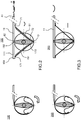
- An arrow 5 indicates the direction of rotation of the mandrel 13.
- the arrow 5 rotates clockwise.
- the main tape measure 11 is wrapped around the mandrel 13 and a portion of the main tape measure 11 comprising the end 81 is extended parallel to the unfolded axis X.
- the mandrel 13 has rotated around the Z axis in the clockwise direction as indicated by the arrow 5.
- the main tape measure 11 extends more along the X axis.
- the secondary tape measure 61 remains wound, its two ends 71, 72 being respectively fixed to the X axis. 81 end of the main tape measure 11 and the mandrel 13.
- the main tape measure 11 is fully deployed.
- the secondary tape measure 61 is also in the deployed position and forms a triangulated structure with the main tape measure 11 and the mandrel 13.
- the triangulated structure thus obtained constitutes a strut, ensures a good maintenance of the main tape measure 11 and gives it good rigidity.
- the figure 2 represents a first variant of a deployable structure 100 comprising two ribbon meters in semi-deployed configuration and deployed according to the invention. All the elements of the deployable structure 100 of the figure 2 are identical to the elements of the deployable structure 10 of the figure 1 .
- the deployable structure comprises a second main tape measure 111 which has a deployment and folding axis substantially parallel to the unfolded axis X, and extends in the opposite direction to the deployment direction of the first main tape measure. 11.
- the second main tape measure 111 has two ends 181, 182.
- the deployable structure 100 comprises a second secondary tape measure 161 which has two ends 171, 172.
- the second main tape measure 111 is also wound around the mandrel 13 As for the first main tape measure 11, a first end 182 of the main tape measure 111 is attached to the mandrel 13. And, like the first secondary tape measure 61, the second secondary tape measure 161 is wound, its two ends 171, 172 being respectively fixed at the end 181 of the main tape measure 111 and the mandrel 13.
- the presence of two main tape-meters allows to deploy a flexible structure of larger area while maintaining a good support and good rigidity of the deployable structure.
- the figure 3 represents a second variant of a deployable structure of two tape-meters in semi-deployed configuration and deployed according to the invention. All elements of the figure 3 are identical to the elements of the figure 2 . On the figure 3 , unlike the figure 2 we do not talk more about secondary tape-meters but secondary struts, since it is no longer a question of tape-meters strictly speaking. Nevertheless, the struts considered contribute in the same way to form a triangular structure constituted by a strut.
- the two secondary struts are flat blades.
- a flat blade in the deployed configuration provides good tensile strength, but offers no compressive strength.
- the blade 61 greatly improves the stiffness of the assembly in the lower stiffness of the tape measure (torque in the counterclockwise direction around Y).
- the opposing blade 161 greatly improves the stiffness of the assembly in the least opposite opposite stiffness direction of the tape measure (clockwise torque around Y).
- the secondary tape-meters constitute a triangulation system on the tape measure 11.
- the figure 4 represents a third variant of a deployable structure of two tape-meters in stored configuration, semi-deployed and deployed according to the invention. All elements of the figure 4 are identical to the elements of the figure 2 .
- the first end 82 of the main tape measure 11 is fixed to the center of the mandrel 13.
- the first end 182 of the main tape measure 11 is fixed to the center of the mandrel 13.
- the two secondary tape-meters 61, 161 are wound, their two ends 71, 72 and 171, 172 respectively being fixed at the end 81, respectively 181 of the main tape-meters 11 and 111 and the mandrel 13.
- the presence of two main tape-meters allows to deploy a flexible structure of larger area while maintaining good support and good rigidity of the deployable structure with both struts.
- this configuration in addition to providing a large flexible structural surface in the deployed position, has the advantage of not being bulky in the stored position.
- the main tape-meters 11, 111 are wound around the mandrel 13 and fixed at its center, there is a high stability of the assembly and a high stiffness to the embedment.
- the mandrel 13 is not positioned at the end of the structure once the main tape-meters 11, 111 unwound. This characteristic plays an important role in the rigidity of the structure.
- FIG. 4 represents two main tape-meters 11 and 111, but the invention also applies to the case with a single main tape-tape attached to the mandrel between its two ends.
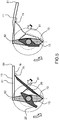
- the figure 5 represents the buckling of the secondary tape measure 61 to obtain the re-winding of the main tape measure 11.
- the main tape measure 11 comprises two faces 15, 16.
- the first end 71 of the secondary tape measure 61 is fixed on a first 16 side of the second end 81 of the main tape measure 11.
- the folding of the strut composed by the tape measure 61 can be achieved by the buckling thereof. Buckling can be achieved by applying a force to the center of the secondary tape measure and normal to it. By doing so, the secondary tape measure 61 flames, that is to say, it no longer forms a triangulated structure with the main tape measure 11 and the mandrel 13.
- the portion of the secondary tape measure 61 located between both ends 71 and 72 approaches the mandrel and tends to rewind.
- the buckling thus initiated allows the winding of the structure. Due to the attachment of the end 71 of the secondary tape measure 61 to the end 81 of the main tape measure 11, the main tape measure 11 is no longer in its fully deployed
- the force applied perpendicularly to the main axis of the main tape measure 61 may be a force applied manually or by motorization.
- the deployable structure 10 is used for only one deployment. Nevertheless, new mission needs appear. Including the transfer or towing of satellite from a low orbit to a high orbit. During the docking, for the control of the transfer vehicle, it takes the least possible inertia, that is to say that the presence of deployable structures of large dimensions is not favorable. We must also avoid any interference with satellites that we seek to dock. As a result, it is preferable to wind up the deployable structures. When the satellite is hooked, we can deploy the structure again.
- FIG. 5 An alternative to applying a force to the main tape measure 11 is also presented on the figure 5 .
- a piece 25 is positioned on the mandrel 13.
- the piece 25 is rotatable about the Z axis.
- To this piece 25 is fixed a blade or a flexible cable 26, connecting the piece 25 to the secondary tape measure 61.
- Rotation of the piece 25 in the direction corresponding to the direction of folding of the main measuring tape moves the secondary tape measure 61 to the mandrel 13 and thus initiates buckling.
- the piece 25 then abuts on the mandrel 13 and thus drives the latter, allowing the winding of the main tape measure 11, the secondary tape measure 61 no longer forming a triangulated structure with the main tape-measure 11 and the mandrel 13.
- the portion of the secondary tape measure 61 located between the two ends 71 and 72 approaches the mandrel and tends to rewind. Due to the attachment of the end 71 of the secondary tape measure 61 to the end 81 of the main tape measure 11, the main tape measure 11 is no longer in its fully extended position. He can then rewind.
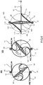
- the figure 6 represents another variant of two ribbon meters of a deployable structure 300 in a semi-deployed and deployed configuration according to the invention. All elements of the figure 6 are identical to the elements of the figure 4 .
- the deployable structure 300 further comprises at least two rollers 20, 21 mounted facing the periphery of the mandrel 13. The rollers 20, 21 are in contact with the tape measures 11, 111.
- the rollers 20, 21 and the shaft 14 are fixed, the mandrel 13 has a degree of freedom in rotation about the Z axis.
- the rollers 20, 21 are able to guide the main tape-meters.
- the rollers 20, 21 provide a guiding function for the tape measures 11, 111.
- the two rollers 20, 21 make it possible in particular to ensure a correct winding of the tape measures 11, 111 around the mandrel 13 during a folding phase and allow to be able to fold the tape measure in flight, for example when the flexible structure is mounted on a satellite.
- the rollers 20, 21 may be heating rollers.
- the heating rollers allow local heating at two points, advantageously diametrically opposite, the tape-meters, thus causing their deployment and also the rotation of the mandrel 13 which can thus heat the tape measure section then brought into contact with the rollers 20, 21, as shown diagrammatically on the figure 6b , the arrows indicating the rotation around the Z axis.
- the local heating by the heating rollers makes it possible to obtain a regulated deployment of the structure.
- this configuration is energetically economical since it is not necessary to heat the entire tape measure and / or chuck. This feature is particularly interesting for use on satellite.
- the invention can be applied to hybrid tape meters, consisting of a first driving structure (for example carbon fiber) that allows the deployment of the tape measure, and a thermoelastic regulating part that promotes or limits the deployment depending on the temperature applied to it.
- a first driving structure for example carbon fiber
- a thermoelastic regulating part that promotes or limits the deployment depending on the temperature applied to it.
- the invention has a simplicity of assembly, with few parts to assemble.
- the progress of the measuring tape is well controlled. Indeed, the tape measure can be guided by the rollers 20, 21, and locally heated in the case where the rollers 20, 21 are heated, thus allowing to regulate its deployment.
- the stacking is autonomous because it is obtained by the bi-stability of the hybrid tape measure with its two stable positions (rolled up and deployed).
Description
La présente invention concerne un procédé d'encastrement escamotable de mètre-ruban pour une structure déployable. Elle concerne aussi une structure déployable comprenant un mètre-ruban. Elle s'applique notamment au domaine des équipements spatiaux qui doivent être déployés en orbite et plus particulièrement aux équipements spatiaux pour satellites, tels que des antennes, des générateurs solaires, des écrans thermiques, des baffles ou des télescopes.The present invention relates to a method of retractable embedding of a tape measure for a deployable structure. It also relates to a deployable structure comprising a tape measure. It applies in particular to the field of space equipment that must be deployed in orbit and more particularly to space equipment for satellites, such as antennas, solar generators, heat shields, baffles or telescopes.
Les structures déployables dans l'espace, de type générateur solaire par exemple, sont généralement constituées de panneaux rigides articulés entre eux, ces panneaux étant, en position stockée, empilés les uns au-dessus des autres. Ces structures ont l'avantage d'avoir une cinématique maîtrisée mais présentent le désavantage d'une masse surfacique et d'une inertie importantes. En outre, les structures rigides occupent, en position stockée, un encombrement important sous la coiffe d'un lanceur. L'espace alloué, aux structures déployables, sous la coiffe d'un lanceur, étant limité, il est important de réduire l'encombrement de ces structures déployables lorsqu'elles sont en position stockée de façon à en optimiser la surface en position déployée.The space-deployable structures, of the solar generator type for example, generally consist of rigid panels hinged together, these panels being, in the stored position, stacked one above the other. These structures have the advantage of having a controlled kinematics but have the disadvantage of a large surface mass and inertia. In addition, the rigid structures occupy, in the stored position, a large space under the cap of a launcher. The space allocated to the deployable structures, under the cap of a launcher, being limited, it is important to reduce the size of these deployable structures when they are in the stored position so as to optimize the surface in the deployed position.
Il existe des structures planes flexibles déployables comportant une toile flexible et des mètres-ruban (aussi connus dans la littérature anglo-saxonne sous le terme tape-spring) fixés sur un même plan de la toile. En position stockée, la toile et les mètres-ruban sont enroulés autour d'un mandrin. Le déploiement de la structure plane flexible est assuré de manière autonome par le déroulement spontané des mètres-ruban lorsque le mandrin est libre en rotation. On peut citer par exemple le brevet
En effet, les mètres-ruban sont connus dans le domaine spatial comme étant des rubans flexibles ayant une section en arc de cercle dont le rayon de courbure est convexe sur une première face et concave sur une deuxième face, ces rubans étant aptes à passer de l'état enroulé à l'état déroulé essentiellement grâce à leur énergie élastique propre. Il existe différents types de ruban ayant des propriétés propres. Les rubans monostables possèdent une position naturelle déployée et nécessitent un maintien en position stockée. Les mètres-ruban monostables ont donc une tendance naturelle à se déployer pour se retrouver dans leur état déroulé. Le déploiement des rubans monostables est souvent anarchique et incontrôlé. Les rubans bistables possèdent deux positions naturelles (position stockée et position déployée) et ne nécessitent pas de maintien en position stockée lorsque la section est totalement applatie. Leur déploiement est linéaire et contrôlé. Cependant, dans tous les cas, lorsque le déploiement est déclenché, celui-ci peut être violent et générateur de chocs, c'est-à-dire que tout le mètre-ruban peut avoir tendance à se remettre droit simultanément, sur toute sa longueur, ce qui pose un risque d'endommagement des éléments environnants ou des éléments fixés sur le mètre-ruban tels que une membrane flexible, un instrument, une antenne... Les mètres-ruban classiques peuvent ainsi présenter des difficultés en termes de contrôle de leur déploiement. Afin de réguler la vitesse de déploiement de ce type de structure, plusieurs méthodes peuvent être utilisées. On peut citer par exemple une régulation par motoréducteur électrique comme décrit dans la demande de brevet
En outre, les mètres-ruban n'ont pas la même raideur suivant l'axe de contrainte. Un effort F appliqué sur la face convexe du mètre-ruban va avoir tendance à faire fléchir le mètre-ruban alors que le même effort appliqué sur la face concave n'aura aucun effet, ce qui pose un problème d'instabilité de la structure flexible dans son état déployé. Pour résoudre ce problème de stabilité de l'état déployé, il est alors nécessaire de maintenir le mètre-ruban en position déployée par un dispositif de maintien supplémentaire ou de sur-dimensionner le mètre-ruban pour qu'il reste stable sous les efforts orbitaux, quels que soient leurs sens d'application.In addition, the tape-meters do not have the same stiffness along the axis of stress. A force F applied on the convex face of the tape measure will have a tendency to bend the tape measure while the same force applied on the concave face will have no effect, which poses a problem of instability of the flexible structure in its unfolded state. To solve this problem of stability of the deployed state, it is then necessary to maintain the tape measure in the extended position by an additional holding device or to oversize the tape measure so that it remains stable under the orbital forces. whatever their application
Ainsi, en configuration stockée, le mètre-ruban doit être le plus compact possible, c'est-à-dire avoir un rayon d'enroulement le plus faible possible. Ce paramètre est donné par les caractéristiques physiques du ruban, généralement, le rayon d'enroulement est sensiblement égal à celui de leur rayon de courbure. Dans le cas d'un ruban composite, il peut être modifié en changeant l'empilage des plis et/ou le sens des fibres. En configuration déployée, la meilleure rigidité possible est recherchée, ce qui signifie une section la plus grande et la plus fermée possible associée à un encastrement de l'extrémité du mètre-ruban le plus important possible.Thus, in stored configuration, the tape measure must be as compact as possible, that is to say have a winding radius as low as possible. This parameter is given by the physical characteristics of the ribbon, generally, the winding radius is substantially equal to that of their radius of curvature. In the case of a composite tape, it can be modified by changing the stack of folds and / or the direction of the fibers. In the deployed configuration, the best possible rigidity is sought, which means a larger and more closed section possible associated with embedding the end of the tape-meter as much as possible.
L'invention vise à pallier tout ou partie des problèmes cités plus haut en proposant un procédé d'encastrement escamotable de mètre-ruban pour une structure déployable, présentant l'avantage d'être peu encombrant, simple à réaliser, présentant une optimisation du volume de la structure déployable lorsqu'elle est stockée sous la coiffe d'un lanceur, permettant la maîtrise du déploiement et une capacité de reploiement et permettant une rigidité et une stabilité de la structure lorsqu'elle est déployée.The invention aims at overcoming all or part of the problems mentioned above by proposing a method of retractable embedding of a tape measure for a deployable structure, having the advantage of being compact, simple to perform, having an optimization of the volume the deployable structure when stored under the casing of a launcher, allowing control of deployment and a folding ability and allowing rigidity and stability of the structure when deployed.
A cet effet, l'invention a pour objet un procédé d'encastrement escamotable de mètre-ruban pour une structure enroulable et déployable, comprenant un mètre-ruban principal ayant un axe de déploiement et de reploiement sensiblement parallèle à un axe déplié X et comportant deux extrémités, un mètre-ruban secondaire comportant deux extrémités et un mandrin d'enroulement porté par un arbre parallèle à un axe Z perpendiculaire à l'axe X, le mètre-ruban principal étant enroulé autour du mandrin, une première extrémité du mètre-ruban principal étant fixée sur le mandrin,
caractérisé en ce qu'il comporte les étapes suivantes :
- Fixation d'une première extrémité du mètre-ruban secondaire à distance d'une deuxième extrémité du mètre-ruban principal,
- Fixation d'une seconde extrémité du mètre-ruban secondaire sur le mandrin.
characterized in that it comprises the following steps:
- Attaching a first end of the secondary tape measure away from a second end of the main tape measure,
- Attaching a second end of the secondary tape measure to the mandrel.
Avantageusement, le procédé d'encastrement escamotable peut comporter au préalable une étape de fixation ponctuelle de la deuxième extrémité du mètre-ruban principal.Advantageously, the retractable embedding method may comprise, beforehand, a point-fixing step of the second end of the main measuring tape.
Avantageusement, le procédé peut comporter les étapes suivantes :
- Déploiement simultané du mètre-ruban principal sensiblement parallèlement à l'axe X et du mètre-ruban secondaire,
- Formation d'une structure triangulée entre le mètre-ruban principal, le mètre-ruban secondaire et le mandrin.
- Simultaneous deployment of the main tape measure substantially parallel to the X axis and the secondary tape measure,
- Formation of a triangulated structure between the main tape measure, the secondary tape measure and the chuck.
Avantageusement, le procédé peut comporter en outre une étape de ré-enroulement du mètre-ruban principal, et le ré-enroulement du mètre-ruban principal peut être obtenu par flambage du mètre-ruban secondaire.Advantageously, the method may further comprise a step of re-winding the main tape-measure, and the re-winding of the main tape-measure may be obtained by buckling of the secondary tape measure.
Avantageusement, le mètre-ruban principal peut comprendre deux faces, la première extrémité du mètre-ruban secondaire peut être fixée sur une première face de la première extrémité du mètre-ruban principal, et le flambage du mètre-ruban secondaire peut être obtenu par application d'une force au centre du mètre-ruban et normale au mètre-ruban secondaire.Advantageously, the main tape measure may comprise two faces, the first end of the secondary tape measure may be fixed on a first face of the first end of the main tape measure, and the buckling of the secondary tape measure may be obtained by application a force in the center of the tape measure and normal to the secondary tape measure.
Avantageusement, la force peut être appliquée entre la première extrémité du mètre-ruban secondaire et la deuxième extrémité du mètre-ruban principal.Advantageously, the force may be applied between the first end of the secondary tape measure and the second end of the main tape measure.
Avantageusement, le procédé d'encastrement escamotable peut comporter en outre une étape de fixation de la première extrémité du mètre-ruban principal au centre du mandrin.Advantageously, the retractable embedding method may further comprise a step of fixing the first end of the main tape measure in the center of the mandrel.
Avantageusement, la structure déployable peut comprendre au moins deux galets montés en vis-à-vis à la périphérie du mandrin, les galets peuvent être en contact avec le mètre-ruban principal, les galets et l'arbre peuvent disposer d'un degré de liberté en rotation autour de l'axe Z l'un par rapport à l'autre. Le procédé d'encastrement escamotable peut comporter les étapes suivantes :
- Guidage local du mètre-ruban principal par les galets,
- Déploiement du mètre-ruban principal dans une direction sensiblement parallèle à l'axe X.
- Local guidance of the main tape measure by the rollers,
- Deployment of the main tape measure in a direction substantially parallel to the X axis.
Avantageusement, les galets peuvent être des galets chauffants, et le procédé d'encastrement escamotable peut comporter au préalable une étape de réchauffage local du mètre-ruban principal par les galets chauffants.Advantageously, the rollers may be heating rollers, and the retractable embedding method may comprise beforehand a local heating step of the main measuring tape by the heating rollers.
L'invention a aussi pour objet une structure déployable comprenant un mètre-ruban principal s'étendant en position déployée selon un axe X et comportant deux extrémités, un mètre-ruban secondaire comportant deux extrémités et un mandrin d'enroulement porté par un arbre selon un axe Z perpendiculaire à l'axe X, le mètre-ruban principal étant enroulé autour du mandrin, une première extrémité du mètre-ruban principal étant fixée sur le mandrin, caractérisé en ce qu'une première extrémité du mètre-ruban secondaire est fixée à distance de la première extrémité du mètre-ruban principal, et en ce qu'une seconde extrémité du mètre-ruban secondaire est fixée sur le mandrin en un point distinct du point de la première extrémité du mètre-ruban principal.The invention also relates to a deployable structure comprising a main tape measure extending in the deployed position along an axis X and having two ends, a secondary tape measure having two ends and a winding mandrel carried by a shaft according to a Z axis perpendicular to the X axis, the main tape measure being wrapped around the mandrel, a first end of the main tape measure being fixed on the mandrel, characterized in that a first end of the secondary tape measure is attached away from the first end of the main tape measure, and that a second end of the secondary tape measure is affixed to the chuck at a point distinct from the point of the first end of the main tape measure.
Avantageusement, la structure déployable comprend au moins deux galets montés en vis-à-vis à la périphérie du mandrin, les galets étant en contact avec le mètre-ruban principal, les galets et l'arbre étant fixes, le mandrin disposant d'un degré de liberté en rotation autour de l'axe Z, les galets étant aptes à guider les mètres-ruban principaux.Advantageously, the deployable structure comprises at least two rollers mounted vis-a-vis at the periphery of the mandrel, the rollers being in contact with the main measuring tape, the rollers and the shaft being fixed, the mandrel having a degree of freedom in rotation about the Z axis, the rollers being able to guide the main tape-meters.
Avantageusement, les galets sont des galets chauffants.Advantageously, the rollers are heating rollers.
L'invention sera mieux comprise et d'autres avantages apparaîtront à la lecture de la description détaillée d'un mode de réalisation donné à titre d'exemple, description illustrée par le dessin joint dans lequel :
- la
figure 1 illustre avec trois schémas, en coupe dans un plan perpendiculaire à l'axe Z, le déploiement d'un mètre-ruban principal selon l'invention, - la
figure 2 représente une première variante de la structure déployable de deux mètres-ruban en configuration semi-déployée et déployée selon l'invention, - la
figure 3 représente une deuxième variante de la structure déployable de deux mètres-ruban en configuration semi-déployée et déployée selon l'invention, - la
figure 4 représente une troisième variante de la structure déployable de deux mètres-ruban en configuration semi-déployée et déployée selon l'invention, - la
figure 5 représente le flambage du mètre-ruban secondaire pour obtenir le ré-enroulement du mètre-ruban principal, - la
figure 6 représente une autre variante de la structure déployable de deux mètres-ruban en configuration semi-déployée et déployée selon l'invention, - la
figure 7 représente les étapes du procédé d'encastrement escamotable selon l'invention.
- the
figure 1 illustrates with three diagrams, in section in a plane perpendicular to the Z axis, the deployment of a main tape measure according to the invention, - the
figure 2 represents a first variant of the deployable structure of two ribbon meters in semi-deployed and deployed configuration according to the invention, - the
figure 3 represents a second variant of the deployable structure of two ribbon meters in a semi-deployed and deployed configuration according to the invention, - the
figure 4 represents a third variant of the deployable structure of two ribbon meters in a semi-deployed and deployed configuration according to the invention, - the
figure 5 represents the buckling of the secondary tape measure to obtain the re-winding of the main tape measure, - the
figure 6 represents another variant of the deployable structure of two ribbon meters in a semi-deployed and deployed configuration according to the invention, - the
figure 7 represents the steps of the retractable embedding method according to the invention.
Par souci de clarté, les mêmes éléments porteront les mêmes repères dans les différentes figures.For the sake of clarity, the same elements will bear the same references in the different figures.
La
- Fixation d'une première extrémité 71 du mètre-
ruban secondaire 61 à distanced'une deuxième extrémité 81 du mètre-rubanprincipal 11, - Fixation
d'une seconde extrémité 72 du mètre-ruban secondaire 61 sur le mandrin 13 en un point distinct du point de la première extrémité 82 du mètre-rubanprincipal 11.
- Attaching a
first end 71 of thesecondary tape measure 61 away from asecond end 81 of themain tape measure 11, - Attaching a
second end 72 of thesecondary tape measure 61 to themandrel 13 at a point distinct from the point of thefirst end 82 of themain tape measure 11.
Une flèche 5 indique le sens de rotation du mandrin 13. Sur le schéma 1a, la flèche 5 tourne dans le sens horaire. Le mètre-ruban principal 11 est enroulé autour du mandrin 13 et une partie du mètre-ruban principal 11 comprenant l'extrémité 81 est déployée parallèlement à l'axe déplié X. Sur le schéma 1b, le mandrin 13 a effectué une rotation autour de l'axe Z dans le sens horaire comme indiqué par la flèche 5. Le mètre-ruban principal 11 se déploie davantage selon l'axe X. Le mètre-ruban secondaire 61 reste enroulé, ses deux extrémités 71, 72 étant fixées respectivement à l'extrémité 81 du mètre-ruban principal 11 et au mandrin 13. Sur le schéma 1c, le mètre-ruban principal 11 est complètement déployé. Le mètre-ruban secondaire 61 est lui aussi en position déployée et forme une structure triangulée avec le mètre-ruban principal 11 et le mandrin 13. La structure triangulée ainsi obtenue constitue une jambe de force, assure un bon maintien du mètre-ruban principal 11 et lui confère une bonne rigidité.An arrow 5 indicates the direction of rotation of the
La
La
Sur la
Il offre par contre une meilleure capacité de stockage qu'un mètre-ruban du fait qu'une section très faible est généralement suffisante pour reprendre les charges en traction.On the other hand, it offers a better storage capacity than a tape measure because a very small section is generally sufficient to take up the loads in tension.
Afin de gagner en encombrement en position stockée, et faciliter l'enroulement, il peut donc être envisagé d'utiliser des câbles, lames planes ou bandes flexibles en remplacement des mètres-ruban. Cependant ceux-ci ne travaillent qu'en traction uniquement. Il faut donc que ceux-ci travaillent par couple et soient mis en opposition en utilisant la raideur du mètre-ruban principal. En effet, lorsqu'on applique un couple sur le mètre-ruban principal, une bande flexible retient l'effort, si on applique un couple dans l'autre sens, c'est la bande flexible opposée qui agit.In order to save space in the stored position, and to facilitate winding, it may therefore be envisaged to use cables, flat blades or flexible strips to replace the tape measures. However, they work only in traction. It is therefore necessary that they work in pairs and are put in opposition using the stiffness of the main tape measure. Indeed, when applying a torque on the main tape measure, a flexible band retains the force, if applying a torque in the other direction, it is the opposite flexible band that acts.
Les mètres-ruban secondaires constituent un système de triangulation sur le mètre-ruban 11.The secondary tape-meters constitute a triangulation system on the
La
Nous pouvons noter toutefois que la
La
La force appliquée perpendiculairement à l'axe principal du mètre-ruban principal 61 peut être une force appliquée manuellement ou par motorisation.The force applied perpendicularly to the main axis of the
Généralement, en utilisation réelle, la structure déployable 10 n'est utilisée que pour un seul déploiement. Néanmoins de nouveaux besoins de mission apparaissent. Notamment le transfert ou le remorquage de satellite d'une orbite basse vers une orbite haute. Lors de l'accostage, pour le pilotage du véhicule de transfert, il faut le moins d'inertie possible, c'est-à-dire que la présence de structures déployables de grandes dimensions n'est pas favorable. Il faut éviter aussi toute interférence avec les satellites que l'on cherche à accoster. De ce fait, il est préférable d'enrouler les structures déployables. Quand le satellite est accroché, on peut de nouveau déployer la structure.Generally, in actual use, the
Une alternative à l'application d'une force sur le mètre-ruban principal 11 est aussi présentée sur la
La
Pour réguler le déploiement des mètres-ruban, il est possible de chauffer le mandrin 13. Avantageusement, les galets 20, 21 peuvent être des galets chauffants. Les galets chauffants permettent de réchauffer localement en deux points, avantageusement diamétralement opposés, les mètres-ruban, provoquant ainsi leur déploiement et également la rotation du mandrin 13 qui peut donc chauffer la section de mètre-ruban alors mise en contact avec les galets 20, 21, comme représenté schématique sur la
La
- Fixation ponctuelle de la deuxième extrémité 81 du mètre-ruban
principal 11,étape 401 - Fixation de la première extrémité 71 du mètre-
ruban secondaire 61 à distance d'une première extrémité 82 du mètre-rubanprincipal 11,étape 402 - Fixation
d'une seconde extrémité 72 du mètre-ruban secondaire 61 sur le mandrin 13,étape 403 - Déploiement simultané du mètre-ruban principal sensiblement parallèlement à l'axe X et du mètre-ruban secondaire,
étape 404 - Formation d'une structure triangulée entre le mètre-ruban principal, le mètre-ruban secondaire et le mandrin,
étape 405.
- Point fixing of the
second end 81 of themain measuring tape 11,step 401 - Attaching the
first end 71 of thesecondary tape measure 61 away from afirst end 82 of themain tape measure 11,step 402 - Attaching a
second end 72 of thesecondary tape measure 61 to themandrel 13,step 403 - Simultaneous deployment of the main tape measure substantially parallel to the X axis and the secondary tape measure,
step 404 - Formation of a triangulated structure between the main tape measure, the secondary tape measure and the chuck,
step 405.
On peut également noter la simplicité d'assemblage ainsi qu'une maîtrise et reproductibilité du couple lors du déploiement et reploiement des mètres-ruban.One can also note the simplicity of assembly as well as a control and reproducibility of the couple during the deployment and folding of the tape-meters.
L'invention peut s'appliquer aux mètres-ruban hybrides, constitués d'une première structure motrice (par exemple en fibre de carbone) qui permet le déploiement du mètre-ruban, et d'une partie régulatrice thermoélastique qui favorise ou limite le déploiement en fonction de la température qui lui est appliquée. Utiliser un phénomène naturel de changement de viscosité d'un matériau thermoplastique (ou d'un matériau ayant une température de transformation sensiblement inférieure à la température de transformation du matériau du ruban moteur) par la température garantit une bonne fiabilité et une reproductibilité du déploiement.The invention can be applied to hybrid tape meters, consisting of a first driving structure (for example carbon fiber) that allows the deployment of the tape measure, and a thermoelastic regulating part that promotes or limits the deployment depending on the temperature applied to it. Using a natural phenomenon of change of viscosity of a thermoplastic material (or a material having a transformation temperature substantially lower than the engine ribbon material processing temperature) by the temperature guarantees good reliability and reproducibility of the deployment.
L'invention présente une simplicité d'assemblage, avec peu de pièces à assembler. Le déroulement du mètre-ruban est bien maîtrisé. En effet, le mètre-ruban peut être guidé par les galets 20, 21, et localement réchauffé dans le cas où les galets 20, 21 sont chauffants, permettant ainsi de réguler son déploiement.The invention has a simplicity of assembly, with few parts to assemble. The progress of the measuring tape is well controlled. Indeed, the tape measure can be guided by the
Enfin, le gerbage est autonome car il est obtenu par la bi-stabilité du mètre-ruban hybride avec ses deux positions stables (enroulée et déployée).Finally, the stacking is autonomous because it is obtained by the bi-stability of the hybrid tape measure with its two stable positions (rolled up and deployed).
Claims (12)
- Retractable tape spring in-building method for a deployable structure, comprising a main tape spring (11) extending in a deployed position along an axis X and comprising two ends (81, 82), a secondary tape spring (61) comprising two ends (71, 72) and a winding mandrel (13) carried by a shaft (14) along an axis Z perpendicular to the axis X, the main tape spring (11) being wound around the mandrel (13), a first end (82) of the main tape spring (11) being fixed to the mandrel (13),
characterized in that it comprises the following steps:• fixing a first end (71) of the secondary tape spring (61) to the main tape spring (11) some distance from the first end (82) of the main tape spring (11),• fixing a second end (72) of the secondary tape spring (61) to the mandrel (13) at a point distinct from the point of the first end (82) of the main tape spring (11), so as to form in a deployed position of the main tape spring (11) a triangulated structure between the main tape spring (11), the secondary tape spring (61) and the mandrel (13). - Retractable in-building method according to Claim 1, characterized in that it comprises beforehand a step of fixing a second end (81) of the main tape spring (11) at a distinct spot.
- Retractable in-building method according to one of the preceding claims, characterized in that it comprises the following steps:• simultaneous deployment of the main tape spring (11) substantially parallel to the axis X and of the secondary tape spring (61),• formation of a triangulated structure between the main tape spring (11), the secondary tape spring (61) and the mandrel (13).
- Retractable in-building method according to one of the preceding claims, characterized in that it further comprises a step of rewinding the main tape spring (11), and in that the rewinding of the main tape spring (11) is obtained by buckling the secondary tape spring (61).
- Retractable in-building method according to Claim 4, the main tape spring (11) comprising two faces (15, 16), characterized in that the first end (71) of the secondary tape spring (61) is fixed to a first face (16) of the second end (81) of the main tape spring (11), and in that the buckling of the secondary tape spring (61) is obtained by applying a force to the middle of the secondary tape spring (61) and normal to the secondary tape spring (61).
- Retractable in-building method according to Claim 5, characterized in that the force is applied between the first end (71) of the secondary tape spring (61) and the second end (81) of the main tape spring (11).
- Retractable in-building method according to one of Claims 1 to 6, characterized in that it further comprises a step of fixing the first end (82) of the main tape spring (11) to the middle of the mandrel (13).
- Retractable in-building method according to Claim 7, the deployable structure comprising at least two rollers (20, 21) mounted facing each other at the periphery of the mandrel (13), the rollers (20, 21) being in contact with the main tape spring (11), and the rollers (20, 21) and the shaft (14) having a degree of freedom to rotate about the axis Z relative to one another, characterized in that it comprises the following steps:• local guidance of the main tape spring (11) by the rollers (20, 21),• deployment of the main tape spring (11) in a direction substantially parallel to the axis X.
- Retractable in-building method according to Claim 8, the rollers being heating rollers, characterized in that it comprises beforehand a step of local heating of the main tape spring (11) by the heating rollers (20, 21).
- Deployable structure comprising a main tape spring (11) extending in a deployed position along an axis X and comprising two ends (81, 82), a secondary tape spring (61) comprising two ends (71, 72) and a winding mandrel (13) carried by a shaft (14) along an axis Z perpendicular to the axis X, the main tape spring (11) being wound around the mandrel (13), a first end (82) of the main tape spring (11) being fixed to the mandrel (13), characterized in that a first end (71) of the secondary tape spring (61) is fixed to the main tape spring (11) some distance from the first end (82) of the main tape spring (11), and in that a second end (72) of the secondary tape spring (61) is fixed to the mandrel (13) at a point distinct from the point of the first end (82) of the main tape spring (11), so as to form in a deployed position of the main tape spring (11) a triangulated structure between the main tape spring (11), the secondary tape spring (61) and the mandrel (13).
- Deployable structure according to Claim 10, characterized in that it comprises at least two rollers (20, 21) mounted facing each other at the periphery of the mandrel (13), in that the rollers (20, 21) are in contact with the main tape spring (11), and in that the rollers (20, 21) and the shaft (14) are fixed, the mandrel (13) having a degree of freedom to rotate about the axis Z, the rollers (20, 21) being able to guide the main tape springs (11, 111).
- Deployable structure according to Claim 11, characterized in that the rollers (20, 21) are heating rollers.
Applications Claiming Priority (1)
| Application Number | Priority Date | Filing Date | Title |
|---|---|---|---|
| FR1401711A FR3024227B1 (en) | 2014-07-25 | 2014-07-25 | RECOVERABLE METER-RIBBON RECESSING METHOD FOR DEPLOYABLE STRUCTURE AND DEPLOYABLE METER-RIBBON STRUCTURE |
Publications (2)
| Publication Number | Publication Date |
|---|---|
| EP2977322A1 EP2977322A1 (en) | 2016-01-27 |
| EP2977322B1 true EP2977322B1 (en) | 2017-09-13 |
Family
ID=52003849
Family Applications (1)
| Application Number | Title | Priority Date | Filing Date |
|---|---|---|---|
| EP15177167.2A Active EP2977322B1 (en) | 2014-07-25 | 2015-07-16 | Method for retractable embedding of a tape measure for a deployable structure and deployable structure with tape measure |
Country Status (6)
| Country | Link |
|---|---|
| US (1) | US9605430B2 (en) |
| EP (1) | EP2977322B1 (en) |
| JP (1) | JP6668009B2 (en) |
| CA (1) | CA2897031C (en) |
| ES (1) | ES2650062T3 (en) |
| FR (1) | FR3024227B1 (en) |
Families Citing this family (18)
| Publication number | Priority date | Publication date | Assignee | Title |
|---|---|---|---|---|
| FR2998876B1 (en) * | 2012-12-05 | 2015-07-17 | Thales Sa | DEVICE FOR DEPLOYING AND REPLOYING A FLEXIBLE STRUCTURE, FLEXIBLE DEPLOYABLE STRUCTURE AND SATELLITE PROVIDED WITH SUCH A DEVICE |
| US10263316B2 (en) * | 2013-09-06 | 2019-04-16 | MMA Design, LLC | Deployable reflectarray antenna structure |
| US9856039B2 (en) * | 2014-10-08 | 2018-01-02 | Analytical Mechanics Associates, Inc. | Extendable solar array for a spacecraft system |
| US20160137319A1 (en) * | 2014-10-24 | 2016-05-19 | Solaero Technologies Corp. | Method for releasing a deployable boom |
| US10059471B2 (en) | 2014-10-24 | 2018-08-28 | Solaero Technologies Corp. | Method for releasing a deployable boom |
| US9004410B1 (en) | 2014-10-24 | 2015-04-14 | Alliance Spacesystems, Llc | Deployable boom for collecting electromagnetic energy |
| FR3029615B1 (en) * | 2014-12-05 | 2018-01-05 | Thales | DEVICE FOR LAUNCHING A PROJECTILE BY COMPRESSED FLUID |
| US10189583B2 (en) * | 2015-05-13 | 2019-01-29 | Analytical Mechanics Associates, Inc. | Deployable sheet material systems and methods |
| FR3048418B1 (en) | 2016-03-02 | 2019-04-19 | Thales | DEVICE FOR DEPLOYING AND POINTING |
| US10752334B2 (en) * | 2016-09-30 | 2020-08-25 | Edward Chow | Collapsible and rapidly-deployable unmanned aerial vehicle |
| CN114279287A (en) * | 2016-10-05 | 2022-04-05 | 米沃奇电动工具公司 | Tape measure with compact retraction system |
| FR3063069B1 (en) * | 2017-02-23 | 2019-04-19 | Centre National D'etudes Spatiales | DEPLOYMENT SYSTEM COMPRISING A MOBILE PLATFORM AND AN OBSERVATION ASSEMBLY COMPRISING AT LEAST TWO RIBBONS |
| FR3087426B1 (en) * | 2018-10-18 | 2022-03-11 | Thales Sa | DEPLOYABLE DEVICE WITH NON CONSTANT AREA TAPE MEASURE |
| WO2020150735A1 (en) * | 2019-01-18 | 2020-07-23 | M.M.A. Design, LLC | Deployable system with flexible membrane |
| FR3098651B1 (en) * | 2019-07-11 | 2022-07-08 | Thales Sa | THREE-DIMENSIONAL DEPLOYMENT DEVICE |
| DE102021102980A1 (en) * | 2021-02-09 | 2022-08-11 | Deployables Cubed GmbH | Boom system for a satellite |
| FR3122861A1 (en) | 2021-05-12 | 2022-11-18 | Centre National d'Études Spatiales | Electrical distribution spacecraft and related method |
| CN113895097B (en) * | 2021-10-25 | 2023-06-23 | 福州大学 | Composite material thin shell plane folding and unfolding device and folding and unfolding method |
Family Cites Families (19)
| Publication number | Priority date | Publication date | Assignee | Title |
|---|---|---|---|---|
| FR803986A (en) | 1935-07-03 | 1936-10-13 | pin to fix the sheets before riveting | |
| FR1203300A (en) | 1958-09-16 | 1960-01-18 | Type of construction with bare-storey platforms for the development of individual light houses | |
| US3213573A (en) * | 1962-07-12 | 1965-10-26 | Thiokol Chemical Corp | Extensible and retractable member |
| US3564789A (en) * | 1968-12-09 | 1971-02-23 | Ryan Aeronautical Co | Extendable-retractable box beam |
| US3785590A (en) * | 1970-12-21 | 1974-01-15 | Communications Satellite Corp | Spacecraft body with roller mechanism for deployable-retractable thin film solar array |
| US3863870A (en) * | 1972-07-10 | 1975-02-04 | Hughes Aircraft Co | Spin stabilized vehicle and solar cell arrangement therefor |
| US4047339A (en) * | 1973-03-29 | 1977-09-13 | Fairchild Industries, Inc. | High load extendible structure |
| DE3838724A1 (en) * | 1987-12-07 | 1989-06-22 | Schmid Hans Armin | DEVICE FOR CARRYING A BOMBED TAPE |
| JPH02136398A (en) * | 1988-11-17 | 1990-05-24 | Mitsubishi Electric Corp | Deployment truss antenna |
| US6904722B2 (en) * | 2001-02-21 | 2005-06-14 | The United States Of America As Represented By The Secretary Of The Navy | Elongated truss boom structures for space applications |
| JP3863411B2 (en) * | 2001-11-12 | 2006-12-27 | 株式会社東芝 | Deployable device |
| ATE416978T1 (en) * | 2004-12-28 | 2008-12-15 | Alcatel Lucent | CONNECTING DEVICE FOR ELEMENTS OF SPACE EQUIPMENT HAVING FLEXIBLE DELIVERY BLADES |
| US7694465B2 (en) * | 2005-04-08 | 2010-04-13 | Alliant Techsystems Inc. | Deployable structural assemblies, systems for deploying such structural assemblies and related methods |
| US7806370B2 (en) * | 2006-03-31 | 2010-10-05 | Composite Technology Development, Inc. | Large-scale deployable solar array |
| US7617639B1 (en) * | 2006-08-08 | 2009-11-17 | The United States Of America As Represented By The Secretary Of The Air Force | Tape-spring deployable boom |
| US7895795B1 (en) * | 2007-10-22 | 2011-03-01 | The United States Of America As Represented By The Secretary Of The Air Force | Triangular rollable and collapsible boom |
| FR2933771B1 (en) * | 2008-07-11 | 2010-08-13 | Thales Sa | THERMALLY DEPLOYABLE TAPE METER AND DEPLOYABLE STRUCTURE COMPRISING SAID METER TAPE |
| FR2969984B1 (en) * | 2010-12-30 | 2013-02-08 | Thales Sa | DISABLED SOLAR GENERATOR CAISSONNE |
| FR2998876B1 (en) * | 2012-12-05 | 2015-07-17 | Thales Sa | DEVICE FOR DEPLOYING AND REPLOYING A FLEXIBLE STRUCTURE, FLEXIBLE DEPLOYABLE STRUCTURE AND SATELLITE PROVIDED WITH SUCH A DEVICE |
-
2014
- 2014-07-25 FR FR1401711A patent/FR3024227B1/en not_active Expired - Fee Related
-
2015
- 2015-07-10 CA CA2897031A patent/CA2897031C/en active Active
- 2015-07-16 JP JP2015141888A patent/JP6668009B2/en active Active
- 2015-07-16 ES ES15177167.2T patent/ES2650062T3/en active Active
- 2015-07-16 EP EP15177167.2A patent/EP2977322B1/en active Active
- 2015-07-21 US US14/805,359 patent/US9605430B2/en active Active
Non-Patent Citations (1)
| Title |
|---|
| None * |
Also Published As
| Publication number | Publication date |
|---|---|
| FR3024227B1 (en) | 2018-02-09 |
| FR3024227A1 (en) | 2016-01-29 |
| EP2977322A1 (en) | 2016-01-27 |
| CA2897031C (en) | 2022-06-21 |
| US20160024790A1 (en) | 2016-01-28 |
| ES2650062T3 (en) | 2018-01-16 |
| US9605430B2 (en) | 2017-03-28 |
| JP6668009B2 (en) | 2020-03-18 |
| JP2016030596A (en) | 2016-03-07 |
| CA2897031A1 (en) | 2016-01-25 |
Similar Documents
| Publication | Publication Date | Title |
|---|---|---|
| EP2977322B1 (en) | Method for retractable embedding of a tape measure for a deployable structure and deployable structure with tape measure | |
| EP2977323B1 (en) | Deployable structure with tape-spring | |
| EP3023333B1 (en) | Retractable and deployable structure with tape measure | |
| EP2471714B1 (en) | Extendable planar solar generator | |
| EP2740669B1 (en) | Device for deploying and retracting a flexible structure, flexible deployable structure and satellite provided with such a device | |
| EP2143641B1 (en) | Tape measure with thermal unrolling and unrolling structure comprising such a tape measure | |
| EP2471713B1 (en) | Unreelable square framed solar generator | |
| EP3640146B1 (en) | Deployable device with tape measure | |
| EP2514674B1 (en) | Device for protecting an optical instrument of a satellite | |
| EP1873061B1 (en) | Retractable structure comprising rigid elements on board a spacecraft | |
| EP2301112A2 (en) | Hinged folding structure | |
| EP3433173B1 (en) | Spacecraft | |
| FR2584045A1 (en) | LARGE HIGH FREQUENCY SOLAR PANEL FOR SATELLITE | |
| EP3176095A1 (en) | Deployable structure comprising a set of solar generators, system for deploying such a deployable structure and satellite comprising such a system | |
| EP2520494B1 (en) | Device for protecting a multiple mirror optical instrument | |
| WO2015092160A1 (en) | Segmented structure, particularly for satellite antenna reflector, provided with at least one strip-comprising unfurling device | |
| FR3101065A1 (en) | DEPLOYABLE DEVICE | |
| FR3110552A1 (en) | Vehicle in orbit with roll-up and deployable membrane for attitude and orbit control | |
| FR3060536A1 (en) | SPACE ENGINE | |
| FR2717207A1 (en) | Unfoldable carrying mast for raising loads |
Legal Events
| Date | Code | Title | Description |
|---|---|---|---|
| PUAI | Public reference made under article 153(3) epc to a published international application that has entered the european phase |
Free format text: ORIGINAL CODE: 0009012 |
|
| AK | Designated contracting states |
Kind code of ref document: A1 Designated state(s): AL AT BE BG CH CY CZ DE DK EE ES FI FR GB GR HR HU IE IS IT LI LT LU LV MC MK MT NL NO PL PT RO RS SE SI SK SM TR |
|
| AX | Request for extension of the european patent |
Extension state: BA ME |
|
| 17P | Request for examination filed |
Effective date: 20160704 |
|
| RBV | Designated contracting states (corrected) |
Designated state(s): AL AT BE BG CH CY CZ DE DK EE ES FI FR GB GR HR HU IE IS IT LI LT LU LV MC MK MT NL NO PL PT RO RS SE SI SK SM TR |
|
| GRAP | Despatch of communication of intention to grant a patent |
Free format text: ORIGINAL CODE: EPIDOSNIGR1 |
|
| RIC1 | Information provided on ipc code assigned before grant |
Ipc: B64G 1/66 20060101ALN20170405BHEP Ipc: B64G 1/22 20060101AFI20170405BHEP Ipc: B64G 1/44 20060101ALN20170405BHEP |
|
| INTG | Intention to grant announced |
Effective date: 20170509 |
|
| GRAS | Grant fee paid |
Free format text: ORIGINAL CODE: EPIDOSNIGR3 |
|
| GRAA | (expected) grant |
Free format text: ORIGINAL CODE: 0009210 |
|
| AK | Designated contracting states |
Kind code of ref document: B1 Designated state(s): AL AT BE BG CH CY CZ DE DK EE ES FI FR GB GR HR HU IE IS IT LI LT LU LV MC MK MT NL NO PL PT RO RS SE SI SK SM TR |
|
| REG | Reference to a national code |
Ref country code: GB Ref legal event code: FG4D Free format text: NOT ENGLISH |
|
| REG | Reference to a national code |
Ref country code: CH Ref legal event code: EP |
|
| REG | Reference to a national code |
Ref country code: IE Ref legal event code: FG4D Free format text: LANGUAGE OF EP DOCUMENT: FRENCH |
|
| REG | Reference to a national code |
Ref country code: CH Ref legal event code: NV Representative=s name: SERVOPATENT GMBH, CH |
|
| REG | Reference to a national code |
Ref country code: AT Ref legal event code: REF Ref document number: 927858 Country of ref document: AT Kind code of ref document: T Effective date: 20171015 |
|
| REG | Reference to a national code |
Ref country code: DE Ref legal event code: R096 Ref document number: 602015004655 Country of ref document: DE |
|
| REG | Reference to a national code |
Ref country code: NL Ref legal event code: FP |
|
| REG | Reference to a national code |
Ref country code: ES Ref legal event code: FG2A Ref document number: 2650062 Country of ref document: ES Kind code of ref document: T3 Effective date: 20180116 |
|
| REG | Reference to a national code |
Ref country code: LT Ref legal event code: MG4D |
|
| PG25 | Lapsed in a contracting state [announced via postgrant information from national office to epo] |
Ref country code: HR Free format text: LAPSE BECAUSE OF FAILURE TO SUBMIT A TRANSLATION OF THE DESCRIPTION OR TO PAY THE FEE WITHIN THE PRESCRIBED TIME-LIMIT Effective date: 20170913 Ref country code: NO Free format text: LAPSE BECAUSE OF FAILURE TO SUBMIT A TRANSLATION OF THE DESCRIPTION OR TO PAY THE FEE WITHIN THE PRESCRIBED TIME-LIMIT Effective date: 20171213 Ref country code: SE Free format text: LAPSE BECAUSE OF FAILURE TO SUBMIT A TRANSLATION OF THE DESCRIPTION OR TO PAY THE FEE WITHIN THE PRESCRIBED TIME-LIMIT Effective date: 20170913 Ref country code: FI Free format text: LAPSE BECAUSE OF FAILURE TO SUBMIT A TRANSLATION OF THE DESCRIPTION OR TO PAY THE FEE WITHIN THE PRESCRIBED TIME-LIMIT Effective date: 20170913 Ref country code: LT Free format text: LAPSE BECAUSE OF FAILURE TO SUBMIT A TRANSLATION OF THE DESCRIPTION OR TO PAY THE FEE WITHIN THE PRESCRIBED TIME-LIMIT Effective date: 20170913 |
|
| REG | Reference to a national code |
Ref country code: AT Ref legal event code: MK05 Ref document number: 927858 Country of ref document: AT Kind code of ref document: T Effective date: 20170913 |
|
| PG25 | Lapsed in a contracting state [announced via postgrant information from national office to epo] |
Ref country code: LV Free format text: LAPSE BECAUSE OF FAILURE TO SUBMIT A TRANSLATION OF THE DESCRIPTION OR TO PAY THE FEE WITHIN THE PRESCRIBED TIME-LIMIT Effective date: 20170913 Ref country code: BG Free format text: LAPSE BECAUSE OF FAILURE TO SUBMIT A TRANSLATION OF THE DESCRIPTION OR TO PAY THE FEE WITHIN THE PRESCRIBED TIME-LIMIT Effective date: 20171213 Ref country code: RS Free format text: LAPSE BECAUSE OF FAILURE TO SUBMIT A TRANSLATION OF THE DESCRIPTION OR TO PAY THE FEE WITHIN THE PRESCRIBED TIME-LIMIT Effective date: 20170913 Ref country code: GR Free format text: LAPSE BECAUSE OF FAILURE TO SUBMIT A TRANSLATION OF THE DESCRIPTION OR TO PAY THE FEE WITHIN THE PRESCRIBED TIME-LIMIT Effective date: 20171214 |
|
| PG25 | Lapsed in a contracting state [announced via postgrant information from national office to epo] |
Ref country code: PL Free format text: LAPSE BECAUSE OF FAILURE TO SUBMIT A TRANSLATION OF THE DESCRIPTION OR TO PAY THE FEE WITHIN THE PRESCRIBED TIME-LIMIT Effective date: 20170913 Ref country code: CZ Free format text: LAPSE BECAUSE OF FAILURE TO SUBMIT A TRANSLATION OF THE DESCRIPTION OR TO PAY THE FEE WITHIN THE PRESCRIBED TIME-LIMIT Effective date: 20170913 Ref country code: RO Free format text: LAPSE BECAUSE OF FAILURE TO SUBMIT A TRANSLATION OF THE DESCRIPTION OR TO PAY THE FEE WITHIN THE PRESCRIBED TIME-LIMIT Effective date: 20170913 |
|
| PG25 | Lapsed in a contracting state [announced via postgrant information from national office to epo] |
Ref country code: SM Free format text: LAPSE BECAUSE OF FAILURE TO SUBMIT A TRANSLATION OF THE DESCRIPTION OR TO PAY THE FEE WITHIN THE PRESCRIBED TIME-LIMIT Effective date: 20170913 Ref country code: IS Free format text: LAPSE BECAUSE OF FAILURE TO SUBMIT A TRANSLATION OF THE DESCRIPTION OR TO PAY THE FEE WITHIN THE PRESCRIBED TIME-LIMIT Effective date: 20180113 Ref country code: EE Free format text: LAPSE BECAUSE OF FAILURE TO SUBMIT A TRANSLATION OF THE DESCRIPTION OR TO PAY THE FEE WITHIN THE PRESCRIBED TIME-LIMIT Effective date: 20170913 Ref country code: SK Free format text: LAPSE BECAUSE OF FAILURE TO SUBMIT A TRANSLATION OF THE DESCRIPTION OR TO PAY THE FEE WITHIN THE PRESCRIBED TIME-LIMIT Effective date: 20170913 Ref country code: AT Free format text: LAPSE BECAUSE OF FAILURE TO SUBMIT A TRANSLATION OF THE DESCRIPTION OR TO PAY THE FEE WITHIN THE PRESCRIBED TIME-LIMIT Effective date: 20170913 |
|
| REG | Reference to a national code |
Ref country code: DE Ref legal event code: R097 Ref document number: 602015004655 Country of ref document: DE |
|
| REG | Reference to a national code |
Ref country code: FR Ref legal event code: PLFP Year of fee payment: 4 |
|
| PLBE | No opposition filed within time limit |
Free format text: ORIGINAL CODE: 0009261 |
|
| STAA | Information on the status of an ep patent application or granted ep patent |
Free format text: STATUS: NO OPPOSITION FILED WITHIN TIME LIMIT |
|
| PG25 | Lapsed in a contracting state [announced via postgrant information from national office to epo] |
Ref country code: DK Free format text: LAPSE BECAUSE OF FAILURE TO SUBMIT A TRANSLATION OF THE DESCRIPTION OR TO PAY THE FEE WITHIN THE PRESCRIBED TIME-LIMIT Effective date: 20170913 |
|
| 26N | No opposition filed |
Effective date: 20180614 |
|
| PG25 | Lapsed in a contracting state [announced via postgrant information from national office to epo] |
Ref country code: MT Free format text: LAPSE BECAUSE OF FAILURE TO SUBMIT A TRANSLATION OF THE DESCRIPTION OR TO PAY THE FEE WITHIN THE PRESCRIBED TIME-LIMIT Effective date: 20170913 |
|
| PG25 | Lapsed in a contracting state [announced via postgrant information from national office to epo] |
Ref country code: SI Free format text: LAPSE BECAUSE OF FAILURE TO SUBMIT A TRANSLATION OF THE DESCRIPTION OR TO PAY THE FEE WITHIN THE PRESCRIBED TIME-LIMIT Effective date: 20170913 |
|
| PG25 | Lapsed in a contracting state [announced via postgrant information from national office to epo] |
Ref country code: LU Free format text: LAPSE BECAUSE OF NON-PAYMENT OF DUE FEES Effective date: 20180716 Ref country code: MC Free format text: LAPSE BECAUSE OF FAILURE TO SUBMIT A TRANSLATION OF THE DESCRIPTION OR TO PAY THE FEE WITHIN THE PRESCRIBED TIME-LIMIT Effective date: 20170913 |
|
| REG | Reference to a national code |
Ref country code: BE Ref legal event code: MM Effective date: 20180731 |
|
| REG | Reference to a national code |
Ref country code: IE Ref legal event code: MM4A |
|
| PG25 | Lapsed in a contracting state [announced via postgrant information from national office to epo] |
Ref country code: IE Free format text: LAPSE BECAUSE OF NON-PAYMENT OF DUE FEES Effective date: 20180716 |
|
| PG25 | Lapsed in a contracting state [announced via postgrant information from national office to epo] |
Ref country code: BE Free format text: LAPSE BECAUSE OF NON-PAYMENT OF DUE FEES Effective date: 20180731 |
|
| PG25 | Lapsed in a contracting state [announced via postgrant information from national office to epo] |
Ref country code: TR Free format text: LAPSE BECAUSE OF FAILURE TO SUBMIT A TRANSLATION OF THE DESCRIPTION OR TO PAY THE FEE WITHIN THE PRESCRIBED TIME-LIMIT Effective date: 20170913 |
|
| PG25 | Lapsed in a contracting state [announced via postgrant information from national office to epo] |
Ref country code: PT Free format text: LAPSE BECAUSE OF FAILURE TO SUBMIT A TRANSLATION OF THE DESCRIPTION OR TO PAY THE FEE WITHIN THE PRESCRIBED TIME-LIMIT Effective date: 20170913 |
|
| REG | Reference to a national code |
Ref country code: CH Ref legal event code: PCAR Free format text: NEW ADDRESS: WANNERSTRASSE 9/1, 8045 ZUERICH (CH) |
|
| PG25 | Lapsed in a contracting state [announced via postgrant information from national office to epo] |
Ref country code: MK Free format text: LAPSE BECAUSE OF NON-PAYMENT OF DUE FEES Effective date: 20170913 Ref country code: CY Free format text: LAPSE BECAUSE OF FAILURE TO SUBMIT A TRANSLATION OF THE DESCRIPTION OR TO PAY THE FEE WITHIN THE PRESCRIBED TIME-LIMIT Effective date: 20170913 Ref country code: HU Free format text: LAPSE BECAUSE OF FAILURE TO SUBMIT A TRANSLATION OF THE DESCRIPTION OR TO PAY THE FEE WITHIN THE PRESCRIBED TIME-LIMIT; INVALID AB INITIO Effective date: 20150716 |
|
| PG25 | Lapsed in a contracting state [announced via postgrant information from national office to epo] |
Ref country code: AL Free format text: LAPSE BECAUSE OF FAILURE TO SUBMIT A TRANSLATION OF THE DESCRIPTION OR TO PAY THE FEE WITHIN THE PRESCRIBED TIME-LIMIT Effective date: 20170913 |
|
| PGFP | Annual fee paid to national office [announced via postgrant information from national office to epo] |
Ref country code: NL Payment date: 20230626 Year of fee payment: 9 Ref country code: FR Payment date: 20230622 Year of fee payment: 9 |
|
| PGFP | Annual fee paid to national office [announced via postgrant information from national office to epo] |
Ref country code: IT Payment date: 20230627 Year of fee payment: 9 Ref country code: GB Payment date: 20230615 Year of fee payment: 9 Ref country code: ES Payment date: 20230808 Year of fee payment: 9 Ref country code: CH Payment date: 20230801 Year of fee payment: 9 |
|
| PGFP | Annual fee paid to national office [announced via postgrant information from national office to epo] |
Ref country code: DE Payment date: 20230613 Year of fee payment: 9 |