EP3023307A1 - Knieairbag - Google Patents
Knieairbag Download PDFInfo
- Publication number
- EP3023307A1 EP3023307A1 EP15466014.6A EP15466014A EP3023307A1 EP 3023307 A1 EP3023307 A1 EP 3023307A1 EP 15466014 A EP15466014 A EP 15466014A EP 3023307 A1 EP3023307 A1 EP 3023307A1
- Authority
- EP
- European Patent Office
- Prior art keywords
- bag
- knee airbag
- instrument panel
- parts
- seam
- Prior art date
- Legal status (The legal status is an assumption and is not a legal conclusion. Google has not performed a legal analysis and makes no representation as to the accuracy of the status listed.)
- Granted
Links
Images
Classifications
-
- B—PERFORMING OPERATIONS; TRANSPORTING
- B60—VEHICLES IN GENERAL
- B60R—VEHICLES, VEHICLE FITTINGS, OR VEHICLE PARTS, NOT OTHERWISE PROVIDED FOR
- B60R21/00—Arrangements or fittings on vehicles for protecting or preventing injuries to occupants or pedestrians in case of accidents or other traffic risks
- B60R21/02—Occupant safety arrangements or fittings, e.g. crash pads
- B60R21/16—Inflatable occupant restraints or confinements designed to inflate upon impact or impending impact, e.g. air bags
- B60R21/20—Arrangements for storing inflatable members in their non-use or deflated condition; Arrangement or mounting of air bag modules or components
- B60R21/205—Arrangements for storing inflatable members in their non-use or deflated condition; Arrangement or mounting of air bag modules or components in dashboards
- B60R21/206—Arrangements for storing inflatable members in their non-use or deflated condition; Arrangement or mounting of air bag modules or components in dashboards in the lower part of dashboards, e.g. for protecting the knees
-
- B—PERFORMING OPERATIONS; TRANSPORTING
- B60—VEHICLES IN GENERAL
- B60R—VEHICLES, VEHICLE FITTINGS, OR VEHICLE PARTS, NOT OTHERWISE PROVIDED FOR
- B60R21/00—Arrangements or fittings on vehicles for protecting or preventing injuries to occupants or pedestrians in case of accidents or other traffic risks
- B60R21/02—Occupant safety arrangements or fittings, e.g. crash pads
- B60R21/16—Inflatable occupant restraints or confinements designed to inflate upon impact or impending impact, e.g. air bags
- B60R21/23—Inflatable members
- B60R21/231—Inflatable members characterised by their shape, construction or spatial configuration
- B60R2021/23169—Inflatable members characterised by their shape, construction or spatial configuration specially adapted for knee protection
-
- B—PERFORMING OPERATIONS; TRANSPORTING
- B60—VEHICLES IN GENERAL
- B60R—VEHICLES, VEHICLE FITTINGS, OR VEHICLE PARTS, NOT OTHERWISE PROVIDED FOR
- B60R21/00—Arrangements or fittings on vehicles for protecting or preventing injuries to occupants or pedestrians in case of accidents or other traffic risks
- B60R21/02—Occupant safety arrangements or fittings, e.g. crash pads
- B60R21/16—Inflatable occupant restraints or confinements designed to inflate upon impact or impending impact, e.g. air bags
- B60R21/23—Inflatable members
- B60R21/235—Inflatable members characterised by their material
- B60R2021/23533—Inflatable members characterised by their material characterised by the manufacturing process
- B60R2021/23538—Sewing
-
- B—PERFORMING OPERATIONS; TRANSPORTING
- B60—VEHICLES IN GENERAL
- B60R—VEHICLES, VEHICLE FITTINGS, OR VEHICLE PARTS, NOT OTHERWISE PROVIDED FOR
- B60R21/00—Arrangements or fittings on vehicles for protecting or preventing injuries to occupants or pedestrians in case of accidents or other traffic risks
- B60R21/02—Occupant safety arrangements or fittings, e.g. crash pads
- B60R21/16—Inflatable occupant restraints or confinements designed to inflate upon impact or impending impact, e.g. air bags
- B60R21/23—Inflatable members
- B60R21/231—Inflatable members characterised by their shape, construction or spatial configuration
Definitions
- the knee airbag of the vehicle which in the deactivated state is arranged in the lower area of the instrument panel, comprises a bag formed of three parts and has two seams for better guidance of the bag as it is unfolded upwards along the instrument panel.
- the knee airbags help to protect the important body parts, especially the lower limbs of the driver and front passenger.
- the knee airbag is an element of passive safety that works on the principle of a classic airbag. It is located at the bottom of the instrument panel. In a head-on collision, the knee airbag prevents contact of the lower extremities with parts of the instrument panel (ignition key, steering column, etc.).
- the knee airbag consists of a fabric bag, gas generator and control unit and is arranged in the folded state in the lower area of the instrument panel of the vehicle.
- the sac of the knee airbag is sewn together from one or two pieces of fabric, one of the two sides of the sack being shortened in the area of the lower edge of the instrument panel to facilitate deployment of the airbag up the instrument panel when activated. Often both sides of the bag are the same size.
- the disadvantage of the prior art resides in the fact that the bag of the knee airbag tends to deploy in the direction X, ie in the direction of the vehicle longitudinal axis between the feet of the driver or front passenger.
- the bag of the knee airbag according to the invention is formed by three parts and has two seams, wherein two connected to the seam bag parts form the side A and a bag part forms the side B.
- the side A and side B of the bag are sewn edge-to-edge to each other.
- this bag In the activated state of the airbag, so when deployed bag, this bag has an L-shaped profile and the side A is applied to the lower and front wall of the instrument panel, while the side B is aligned with the vehicle interior.
- a seam is arranged on the bag so that in the activated state of the airbag, so when unfolded bag, this seam is applied to the lower edge of the instrument panel, where it connects the two bag parts of the side A of the knee airbag.
- This seam is formed by the connection of the lower edge of the bag top and the upper edge of the bag bottom.
- the second seam is designed such that in the activated state of the knee airbag, that is, when the bag is deployed, this seam is arranged in the bag upper part, wherein it connects the one upper part of the side A and the one part of the side B.
- the bag has in the activated state of the knee airbag in the front view of the side A and B a mushroom-like shape, the lower foot part is lower than the upper part.
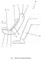
- the Fig. 1 shows a side view of the vehicle instrument panel and the bag of the knee airbag of the vehicle in the activated state
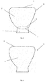
- the Fig. 2 shows the side A of the bag of the knee airbag before the formation of the seam between both parts of the bag
- the Fig. 3 Side B view of the bag of the knee airbag.
- the Fig. 1 shows in which prevents contact of the rider's foot or passenger 40 with the parts of the instrument panel 20 in the activated state, the knee airbag, the side view of the vehicle instrument panel 20 and the bag 10 of the knee airbag of the vehicle.
- the knee airbag can be arranged on the driver's side as well as on the passenger's side.
- the knee airbag consists of a fabric bag, gas generator and control unit and is arranged in the folded state in the lower area of the instrument panel of the vehicle. It can be accommodated in an airbag housing 30 .
- the bag 10 of the knee airbag according to the present invention is formed by three parts 1 , 2 , 3 and has two seams 4 , 5 , wherein two associated with the seam 4 bag parts 1 , 2 form the side A and part 3 of the bag 10 the Side B forms. Side A and side B of the bag 10 are sewn edge-to-edge to each other.
- this bag 10 In the activated state of the airbag, so when deployed bag 10 , this bag 10 has an L-shaped profile and the side A is applied to the lower 21 and front 22 wall of the instrument panel 20 , while the side B is aligned with the vehicle interior 60 .
- a seam 4 is arranged on the bag so that in the activated state of the airbag, so when deployed bag 10 , this seam 4 is applied to the lower edge 23 of the instrument panel 20 , wherein the two bag parts 1 , 2 of the side A of Knee airbags 10 connects.
- This seam 4 is formed by the connection of the lower edge 6 of the bag 2 and the upper part of the upper edge 7 of the bag bottom part 1.
- the second seam 5 is designed such that in the activated state of the knee airbag, that is, when the bag 10 is deployed , this seam is arranged in the bag top 10 , wherein it connects the one upper part 2 of the side A and the one part 3 of the side B. ,
- the Fig. 2 shows the side A of the bag 10 of the knee airbag before the formation of the seam between the two parts 1 , 2 of the bag and the Fig. 3 the view of the side B of the bag 10 of the knee airbag.
- FIGS. 2 and 3 It can be seen that the shape and area of the parts 1 and 2 of the side A are substantially equal to the part 3 of the side B. Before the formation of the seam 4 on the side A is between the two parts 1 and 2, an elliptical or lenticular opening. When the airbag 10 of the knee airbag is activated, this results in a joint in the region of the lower edge 23 of the instrument panel 20 . The length of the lower edge 21 of the instrument panel 20 corresponds to the length of the first part 1 of the side A of the bag 10 .
- the bag has in the activated state of the knee airbag in the front view of the side A and B a mushroom-like shape, the lower foot part is lower than the upper part.
- the knee airbag can be used in passenger vehicles.
Landscapes
- Engineering & Computer Science (AREA)
- Mechanical Engineering (AREA)
- Air Bags (AREA)
Abstract
Description
- Der Knieairbag des Fahrzeuges, der im deaktivierten Zustand im unteren Bereich der Instrumententafel angeordnet ist, umfasst einen aus drei Teilen gebildeten Sack und weist zwei Nähte für eine bessere Führung des Sacks bei seinem Entfalten nach oben entlang der Instrumententafel auf.
- Die Knieairbags helfen die wichtigen Körperteile zu schützen, insbesondere dann die unteren Gliedmaßen des Fahrers und Beifahrers.
- Der Knieairbag ist ein Element der passiven Sicherheit, das nach dem Prinzip eines klassischen Airbags funktioniert. Er ist im unteren Bereich der Instrumententafel angeordnet. Bei einer Frontalkollision verhindert der Knieairbag den Kontakt der unteren Extremitäten mit den Teilen der Instrumententafel (Zündschlüssel, Lenksäule, usw.).
- Der Knieairbag besteht aus einem Gewebesack, Gasgenerator und Steuergerät und ist im zusammengefalteten Zustand im unteren Bereich der Instrumententafel des Fahrzeuges angeordnet.
- Der Sack des Knieairbags ist aus einem oder zwei Gewebestücken zusammengenäht, wobei einer der beiden Seiten des Sacks im Bereich der unteren Kante der Instrumententafel verkürzt ist, um die Entfaltung des Luftsacks nach oben entlang der Instrumententafel bei seiner Aktivierung zu erleichtern. Oft sind beide Sackseiten des Airbags gleich groß.
- Der Nachteil des bisherigen Standes der Technik liegt in der Tatsache, dass sich der Sack des Knieairbags tendenziell in der Richtung X entfaltet, also in der Richtung der Fahrzeuglängsachse zwischen die Füße des Fahrers oder Beifahrers.
- Die Aufgabe der Erfindung, den oben genannten Nachteil des bisherigen Standes der Technik zu beseitigen, wird durch die vorliegende erfindungsgemäße technische Lösung gelöst.
- Der Sack des erfindungsgemäßen Knieairbags wird durch drei Teile gebildet und weist zwei Nähte auf, wobei zwei mit der Naht verbundene Sackteile die Seite A bilden und ein Sackteil die Seite B bildet. Die Seite A und die Seite B des Sacks sind randumlaufend zueinander genäht.
- In dem aktivierten Zustand des Airbags, also beim entfalteten Sack, hat dieser Sack ein L-förmiges Profil und die Seite A liegt zur unteren und vorderen Wand der Instrumententafel an, während die Seite B ins Fahrzeuginnere ausgerichtet ist.
- Eine Naht ist am Sack so angeordnet, dass im aktivierten Zustand des Airbags, also beim entfalteten Sack, diese Naht zu der Unterkante der Instrumententafel anliegt, wobei sie die zwei Sackteile der Seite A des Knieairbags verbindet. Diese Naht wird gebildet durch die Verbindung des unteren Randes des Sackoberteils und des oberen Randes des Sackunterteils.
- Die zweite Naht ist so ausgebildet, dass in dem aktivierten Zustand des Knieairbags, also beim entfalteten Sack, diese Naht in dem Sackoberteil angeordnet ist, wobei sie den einen oberen Teil der Seite A und den einen Teil der Seite B verbindet.
- Der Sack hat im aktivierten Zustand des Knieairbags bei der Frontansicht der Seite A sowie B eine pilzartige Gestalt, deren unterer Fußteil niedriger als der obere Teil ist.
- Die
Fig. 1 zeigt eine Seitenansicht der Fahrzeuginstrumententafel und des Sacks des Knieairbags des Fahrzeuges im aktivierten Zustand, dieFig. 2 zeigt die Seite A des Sacks des Knieairbags vor der Bildung der Naht zwischen beiden Teilen des Sacks und dieFig. 3 die Ansicht der Seite B des Sacks des Knieairbags. - Die
Fig. 1 zeigt die Seitenansicht der Fahrzeuginstrumententafel 20 und des Sacks 10 des Knieairbags des Fahrzeuges im aktivierten Zustand, in dem der Knieairbag den Kontakt des Fußes des Fahrers oder Beifahrers 40 mit den Teilen der Instrumententafel 20 verhindert. Der Knieairbag kann sowohl auf der Fahrerseite, wie auch an der Beifahrerseite angeordnet werden. - Der Knieairbag besteht aus einem Gewebesack, Gasgenerator und Steuergerät und ist im zusammengefalteten Zustand im unteren Bereich der Instrumententafel des Fahrzeuges angeordnet. Er kann in einem Airbaggehäuse 30 untergebracht werden.
- Der Sack 10 des Knieairbags nach vorliegender Erfindung wird gebildet durch drei Teile 1, 2, 3 und weist zwei Nähte 4, 5 auf, wobei zwei mit der Naht 4 verbundenen Sackteile 1, 2 die Seite A bilden und ein Teil 3 des Sacks 10 die Seite B bildet. Seite A und Seite B des Sacks 10 sind randumlaufend zueinander genäht.
- In dem aktivierten Zustand des Airbags, also beim entfalteten Sack 10, hat dieser Sack 10 ein L-förmiges Profil und die Seite A liegt zur unteren 21 und vorderen 22 Wand der Instrumententafel 20 an, während die Seite B ins Fahrzeuginnere 60 ausgerichtet ist.
- Eine Naht 4 ist am Sack so angeordnet, dass im aktivierten Zustand des Airbags, also beim entfalteten Sack 10, diese Naht 4 zu der Unterkante 23 der Instrumententafel 20 anliegt, wobei sie die zwei Sackteile 1, 2 der Seite A des Knieairbags 10 verbindet. Diese Naht 4 wird gebildet durch die Verbindung des unteren Randes 6 des Sackoberteils 2 und des oberen Randes 7 des Sackunterteils 1.
- Die zweite Naht 5 ist so ausgebildet, dass in dem aktivierten Zustand des Knieairbags, also beim entfalteten Sack 10, diese Naht in dem Sackoberteil 10 angeordnet ist, wobei sie den einen oberen Teil 2 der Seite A und den einen Teil 3 der Seite B verbindet.
- Die
Fig. 2 zeigt die Seite A des Sacks 10 des Knieairbags vor der Bildung der Naht zwischen beiden Teilen 1, 2 des Sacks und dieFig. 3 die Ansicht der Seite B des Sacks 10 des Knieairbags. - Aus
Fig. 2 und 3 ist zu entnehmen, dass die Form und Fläche der Teile 1 und 2 der Seite A im Wesentlichen gleich mit dem Teil 3 der Seite B sind. Vor der Bildung der Naht 4 an der Seite A ist zwischen den beiden Teilen 1 und 2 eine ellipsen- bzw. linsenförmige Öffnung. Bei der Aktivierung des Luftsacks 10 des Knieairbags entsteht dadurch ein Gelenk im Bereich der unteren Kante 23 der Instrumententafel 20. Die Länge der unteren Kante 21 der Instrumententafel 20 entspricht der Länge des ersten Teils 1 der Seite A des Sacks 10. - Der Sack hat im aktivierten Zustand des Knieairbags bei der Frontansicht der Seite A sowie B eine pilzartige Gestalt, deren unterer Fußteil niedriger als der obere Teil ist.
- Der Knieairbag kann in Personenkraftfahrzeugen eingesetzt werden.
-
- 1 -
- erste (untere) Teil des Sacks des Knieairbags
- 2 -
- zweite (obere) Teil des Sacks des Knieairbags
- 3 -
- dritte Teil des Sacks des Knieairbags
- 4, 5 -
- Nähte
- 6 -
- unterer Rand des zweiten Teils
- 7 -
- oberer Rand des ersten Teils
- 10 -
- Sack des Knieairbags
- 20 -
- Instrumententafel
- 21 -
- untere Wand der Instrumententafel
- 22 -
- Vorderwand der Instrumententafel
- 23 -
- untere Kante der Instrumententafel
- 30 -
- Airbaggehäuse
- 40 -
- Fahrer- oder Beifahrerfuß
- 50 -
- Richtung X
- 60 -
- Fahrzeuginterieur
Claims (7)
- Knieairbag bestehend aus einem Gewebesack (10), Gasgenerator und Steuereinheit, im zusammengefalteten Zustand unter der Instrumententafel (20) des Fahrzeuges angeordnet, dadurch gekennzeichnet, dass der Sack (10) durch drei Teile (1, 2, 3) gebildet wird und zwei Nähte (4, 5) aufweist, wobei die Teile (1) und (2) des Sacks (10) die Seite bilden und der Teil (3) des Sacks (10) die Seite B bildet.
- Knieairbag nach Anspruch 1 dadurch gekennzeichnet, dass in dem aktivierten Zustand des Airbags, also beim entfalteten Sack (10), dieser Sack (10) ein L-förmiges Profil hat und mit der Seite A an die untere (21) und vordere (22) Wand der Instrumententafel (20) anliegt, während die Seite B ins Fahrzeuginnere (60) ausgerichtet ist.
- Knieairbag nach vorgenannten Ansprüchen dadurch gekennzeichnet, dass die erste Naht (4) an dem Sack (10) so angeordnet ist, dass im aktivierten Zustand des Airbags, also beim entfalteten Sack (10), zu der Unterkante (23) der Instrumententafel (20) anliegt, wobei sie die Teile (1) und (2) verbindet.
- Knieairbag nach vorgenannten Ansprüchen dadurch gekennzeichnet, dass die erste Naht (4) durch die Verbindung des unteren Randes (6) des Oberteils (2) und des oberen Randes (7) des Unterteils (1) des Sacks (10) gebildet wird.
- Knieairbag nach vorgenannten Ansprüchen dadurch gekennzeichnet, dass die zweite Naht (5) so gebildet wird, dass im aktivierten Zustand des Knieairbags, also beim entfalteten Sack (10), sie in dem oberen Sackteil (10) angeordnet ist und die Teile (2) und (3) verbindet.
- Knieairbag nach vorgenannten Ansprüchen dadurch gekennzeichnet, dass der Sack (10) im aktivierten Zustand des Knieairbags bei einer Frontansicht der Seite A sowie B eine pilzartige Gestalt aufweist, deren unterer Fußteil niedriger als der obere Teil ist.
- Knieairbag nach vorgenannten Ansprüchen dadurch gekennzeichnet, dass die Seite A und Seite B des Sacks (10) randumlaufend mit Nähten verbunden sind.
Applications Claiming Priority (1)
| Application Number | Priority Date | Filing Date | Title |
|---|---|---|---|
| CZ2014-797A CZ2014797A3 (cs) | 2014-11-18 | 2014-11-18 | Kolenní airbag |
Publications (2)
| Publication Number | Publication Date |
|---|---|
| EP3023307A1 true EP3023307A1 (de) | 2016-05-25 |
| EP3023307B1 EP3023307B1 (de) | 2017-10-25 |
Family
ID=55168116
Family Applications (1)
| Application Number | Title | Priority Date | Filing Date |
|---|---|---|---|
| EP15466014.6A Active EP3023307B1 (de) | 2014-11-18 | 2015-11-13 | Knieairbag |
Country Status (2)
| Country | Link |
|---|---|
| EP (1) | EP3023307B1 (de) |
| CZ (1) | CZ2014797A3 (de) |
Citations (4)
| Publication number | Priority date | Publication date | Assignee | Title |
|---|---|---|---|---|
| DE202004014653U1 (de) * | 2004-09-14 | 2004-12-02 | Takata-Petri Ag | Gassack zum Schutz des Kniebereichs eines Fahrzeuginsassen |
| DE10355487A1 (de) * | 2003-11-27 | 2005-07-14 | Trw Occupant Restraint Systems Gmbh & Co. Kg | Gassack für ein Fahrzeuginsassen-Rückhaltesystem |
| DE102007000615A1 (de) * | 2006-11-02 | 2008-06-19 | Toyota Jidosha Kabushiki Kaisha, Toyota | Knieairbagvorrichtung |
| WO2014163337A1 (en) * | 2013-04-03 | 2014-10-09 | Autoliv Development Ab | Airbag for knee airbag apparatus |
Family Cites Families (1)
| Publication number | Priority date | Publication date | Assignee | Title |
|---|---|---|---|---|
| DE102014007035A1 (de) * | 2014-05-13 | 2015-11-19 | Autoliv Development Ab | Kniegassack, Kniegassackmodul und Kniegassackmodul-Anordnung in einem Kraftfahrzeug |
-
2014
- 2014-11-18 CZ CZ2014-797A patent/CZ2014797A3/cs unknown
-
2015
- 2015-11-13 EP EP15466014.6A patent/EP3023307B1/de active Active
Patent Citations (4)
| Publication number | Priority date | Publication date | Assignee | Title |
|---|---|---|---|---|
| DE10355487A1 (de) * | 2003-11-27 | 2005-07-14 | Trw Occupant Restraint Systems Gmbh & Co. Kg | Gassack für ein Fahrzeuginsassen-Rückhaltesystem |
| DE202004014653U1 (de) * | 2004-09-14 | 2004-12-02 | Takata-Petri Ag | Gassack zum Schutz des Kniebereichs eines Fahrzeuginsassen |
| DE102007000615A1 (de) * | 2006-11-02 | 2008-06-19 | Toyota Jidosha Kabushiki Kaisha, Toyota | Knieairbagvorrichtung |
| WO2014163337A1 (en) * | 2013-04-03 | 2014-10-09 | Autoliv Development Ab | Airbag for knee airbag apparatus |
Also Published As
| Publication number | Publication date |
|---|---|
| CZ2014797A3 (cs) | 2016-05-25 |
| EP3023307B1 (de) | 2017-10-25 |
Similar Documents
| Publication | Publication Date | Title |
|---|---|---|
| DE102006056603B4 (de) | Fahrzeuginsassen-Rückhaltesystem | |
| EP1826073B1 (de) | Knieairbag | |
| DE112004001981T5 (de) | System zum Halten eines aufblasbaren Kissens | |
| WO2016041626A1 (de) | Adaptives, entfaltbares rückhalteelement für ein fahrzeugsicherheitssystem, gassackmodul und fahrzeugsicherheitssystem mit einem solchen rückhalteelement sowie verwendung des flossenstrahleffekts in einem adaptiven rückhalteelement | |
| DE69803370T2 (de) | Luftsack | |
| WO2000040439A1 (de) | Airbagmodul | |
| EP2582551B1 (de) | Knieairbaganordnung für fahrzeuge | |
| EP3107767B1 (de) | Seitenairbag für fahrzeuge | |
| DE102017131121A1 (de) | Fahrzeuginsassenschutzsystem, Fahrzeugsitz sowie Verfahren zum Entfalten eines Gassacks | |
| WO2015036116A1 (de) | Verfahren zum schützen eines fahrzeuginsassen sowie gassack | |
| DE102014100550B4 (de) | Produkt, das ein Fahrzeug mit einem Dachrahmen-Airbag umfasst | |
| EP3697649A1 (de) | Fahrzeuginsassen-rückhaltesystem mit einem gassackmodul | |
| DE102015012180B4 (de) | Beifahrersitzairbag | |
| EP1062126B1 (de) | Airbagmodul, insbesondere beifahrerairbagmodul | |
| DE10039555B4 (de) | Gassack und Verfahren zur Herstellung eines Gassackes | |
| DE102016209584B4 (de) | Fahrzeugsitzanordnung für ein Kraftfahrzeug | |
| DE102020134796B4 (de) | Airbagkissen für ein Fahrzeug | |
| DE102013015682A1 (de) | Airbag | |
| DE102012021987B4 (de) | Airbag und Verfahren zur Herstellung eines Airbags | |
| EP1531098B1 (de) | Airbag | |
| EP3023307B1 (de) | Knieairbag | |
| DE102011005057B4 (de) | Gassack für ein Fahrzeuginsassen-Rückhaltesystem eines Kraftfahrzeuges und Verfahren zum Herstellen eines derartigen Gassacks | |
| DE102013113434B4 (de) | Gassackmodul mit einer eine Aufspringfalte aufweisenden Venteinrichtung | |
| DE102004033012B4 (de) | Kraftfahrzeug mit einem Vorhang-Gassack | |
| WO2017140719A1 (de) | Kopfschutz-gassackmodul |
Legal Events
| Date | Code | Title | Description |
|---|---|---|---|
| AK | Designated contracting states |
Kind code of ref document: A1 Designated state(s): AL AT BE BG CH CY CZ DE DK EE ES FI FR GB GR HR HU IE IS IT LI LT LU LV MC MK MT NL NO PL PT RO RS SE SI SK SM TR |
|
| AX | Request for extension of the european patent |
Extension state: BA ME |
|
| PUAI | Public reference made under article 153(3) epc to a published international application that has entered the european phase |
Free format text: ORIGINAL CODE: 0009012 |
|
| 17P | Request for examination filed |
Effective date: 20161125 |
|
| RBV | Designated contracting states (corrected) |
Designated state(s): AL AT BE BG CH CY CZ DE DK EE ES FI FR GB GR HR HU IE IS IT LI LT LU LV MC MK MT NL NO PL PT RO RS SE SI SK SM TR |
|
| GRAP | Despatch of communication of intention to grant a patent |
Free format text: ORIGINAL CODE: EPIDOSNIGR1 |
|
| RIC1 | Information provided on ipc code assigned before grant |
Ipc: B60R 21/231 20110101ALI20170720BHEP Ipc: B60R 21/235 20060101ALI20170720BHEP Ipc: B60R 21/206 20110101AFI20170720BHEP |
|
| INTG | Intention to grant announced |
Effective date: 20170811 |
|
| GRAS | Grant fee paid |
Free format text: ORIGINAL CODE: EPIDOSNIGR3 |
|
| GRAA | (expected) grant |
Free format text: ORIGINAL CODE: 0009210 |
|
| AK | Designated contracting states |
Kind code of ref document: B1 Designated state(s): AL AT BE BG CH CY CZ DE DK EE ES FI FR GB GR HR HU IE IS IT LI LT LU LV MC MK MT NL NO PL PT RO RS SE SI SK SM TR |
|
| REG | Reference to a national code |
Ref country code: GB Ref legal event code: FG4D Free format text: NOT ENGLISH |
|
| REG | Reference to a national code |
Ref country code: CH Ref legal event code: EP |
|
| REG | Reference to a national code |
Ref country code: AT Ref legal event code: REF Ref document number: 939611 Country of ref document: AT Kind code of ref document: T Effective date: 20171115 |
|
| REG | Reference to a national code |
Ref country code: IE Ref legal event code: FG4D Free format text: LANGUAGE OF EP DOCUMENT: GERMAN |
|
| REG | Reference to a national code |
Ref country code: DE Ref legal event code: R096 Ref document number: 502015002192 Country of ref document: DE |
|
| REG | Reference to a national code |
Ref country code: NL Ref legal event code: MP Effective date: 20171025 |
|
| REG | Reference to a national code |
Ref country code: LT Ref legal event code: MG4D |
|
| PG25 | Lapsed in a contracting state [announced via postgrant information from national office to epo] |
Ref country code: NL Free format text: LAPSE BECAUSE OF FAILURE TO SUBMIT A TRANSLATION OF THE DESCRIPTION OR TO PAY THE FEE WITHIN THE PRESCRIBED TIME-LIMIT Effective date: 20171025 |
|
| PG25 | Lapsed in a contracting state [announced via postgrant information from national office to epo] |
Ref country code: FI Free format text: LAPSE BECAUSE OF FAILURE TO SUBMIT A TRANSLATION OF THE DESCRIPTION OR TO PAY THE FEE WITHIN THE PRESCRIBED TIME-LIMIT Effective date: 20171025 Ref country code: ES Free format text: LAPSE BECAUSE OF FAILURE TO SUBMIT A TRANSLATION OF THE DESCRIPTION OR TO PAY THE FEE WITHIN THE PRESCRIBED TIME-LIMIT Effective date: 20171025 Ref country code: SE Free format text: LAPSE BECAUSE OF FAILURE TO SUBMIT A TRANSLATION OF THE DESCRIPTION OR TO PAY THE FEE WITHIN THE PRESCRIBED TIME-LIMIT Effective date: 20171025 Ref country code: LT Free format text: LAPSE BECAUSE OF FAILURE TO SUBMIT A TRANSLATION OF THE DESCRIPTION OR TO PAY THE FEE WITHIN THE PRESCRIBED TIME-LIMIT Effective date: 20171025 Ref country code: NO Free format text: LAPSE BECAUSE OF FAILURE TO SUBMIT A TRANSLATION OF THE DESCRIPTION OR TO PAY THE FEE WITHIN THE PRESCRIBED TIME-LIMIT Effective date: 20180125 |
|
| PG25 | Lapsed in a contracting state [announced via postgrant information from national office to epo] |
Ref country code: LV Free format text: LAPSE BECAUSE OF FAILURE TO SUBMIT A TRANSLATION OF THE DESCRIPTION OR TO PAY THE FEE WITHIN THE PRESCRIBED TIME-LIMIT Effective date: 20171025 Ref country code: HR Free format text: LAPSE BECAUSE OF FAILURE TO SUBMIT A TRANSLATION OF THE DESCRIPTION OR TO PAY THE FEE WITHIN THE PRESCRIBED TIME-LIMIT Effective date: 20171025 Ref country code: GR Free format text: LAPSE BECAUSE OF FAILURE TO SUBMIT A TRANSLATION OF THE DESCRIPTION OR TO PAY THE FEE WITHIN THE PRESCRIBED TIME-LIMIT Effective date: 20180126 Ref country code: IS Free format text: LAPSE BECAUSE OF FAILURE TO SUBMIT A TRANSLATION OF THE DESCRIPTION OR TO PAY THE FEE WITHIN THE PRESCRIBED TIME-LIMIT Effective date: 20180225 Ref country code: BG Free format text: LAPSE BECAUSE OF FAILURE TO SUBMIT A TRANSLATION OF THE DESCRIPTION OR TO PAY THE FEE WITHIN THE PRESCRIBED TIME-LIMIT Effective date: 20180125 Ref country code: RS Free format text: LAPSE BECAUSE OF FAILURE TO SUBMIT A TRANSLATION OF THE DESCRIPTION OR TO PAY THE FEE WITHIN THE PRESCRIBED TIME-LIMIT Effective date: 20171025 |
|
| REG | Reference to a national code |
Ref country code: DE Ref legal event code: R097 Ref document number: 502015002192 Country of ref document: DE |
|
| PG25 | Lapsed in a contracting state [announced via postgrant information from national office to epo] |
Ref country code: DK Free format text: LAPSE BECAUSE OF FAILURE TO SUBMIT A TRANSLATION OF THE DESCRIPTION OR TO PAY THE FEE WITHIN THE PRESCRIBED TIME-LIMIT Effective date: 20171025 Ref country code: CY Free format text: LAPSE BECAUSE OF FAILURE TO SUBMIT A TRANSLATION OF THE DESCRIPTION OR TO PAY THE FEE WITHIN THE PRESCRIBED TIME-LIMIT Effective date: 20171025 Ref country code: EE Free format text: LAPSE BECAUSE OF FAILURE TO SUBMIT A TRANSLATION OF THE DESCRIPTION OR TO PAY THE FEE WITHIN THE PRESCRIBED TIME-LIMIT Effective date: 20171025 Ref country code: SK Free format text: LAPSE BECAUSE OF FAILURE TO SUBMIT A TRANSLATION OF THE DESCRIPTION OR TO PAY THE FEE WITHIN THE PRESCRIBED TIME-LIMIT Effective date: 20171025 Ref country code: MC Free format text: LAPSE BECAUSE OF FAILURE TO SUBMIT A TRANSLATION OF THE DESCRIPTION OR TO PAY THE FEE WITHIN THE PRESCRIBED TIME-LIMIT Effective date: 20171025 |
|
| PG25 | Lapsed in a contracting state [announced via postgrant information from national office to epo] |
Ref country code: PL Free format text: LAPSE BECAUSE OF FAILURE TO SUBMIT A TRANSLATION OF THE DESCRIPTION OR TO PAY THE FEE WITHIN THE PRESCRIBED TIME-LIMIT Effective date: 20171025 Ref country code: RO Free format text: LAPSE BECAUSE OF FAILURE TO SUBMIT A TRANSLATION OF THE DESCRIPTION OR TO PAY THE FEE WITHIN THE PRESCRIBED TIME-LIMIT Effective date: 20171025 Ref country code: LU Free format text: LAPSE BECAUSE OF NON-PAYMENT OF DUE FEES Effective date: 20171113 Ref country code: IT Free format text: LAPSE BECAUSE OF FAILURE TO SUBMIT A TRANSLATION OF THE DESCRIPTION OR TO PAY THE FEE WITHIN THE PRESCRIBED TIME-LIMIT Effective date: 20171025 Ref country code: SM Free format text: LAPSE BECAUSE OF FAILURE TO SUBMIT A TRANSLATION OF THE DESCRIPTION OR TO PAY THE FEE WITHIN THE PRESCRIBED TIME-LIMIT Effective date: 20171025 |
|
| PLBE | No opposition filed within time limit |
Free format text: ORIGINAL CODE: 0009261 |
|
| REG | Reference to a national code |
Ref country code: FR Ref legal event code: ST Effective date: 20180731 Ref country code: BE Ref legal event code: MM Effective date: 20171130 |
|
| STAA | Information on the status of an ep patent application or granted ep patent |
Free format text: STATUS: NO OPPOSITION FILED WITHIN TIME LIMIT |
|
| REG | Reference to a national code |
Ref country code: IE Ref legal event code: MM4A |
|
| PG25 | Lapsed in a contracting state [announced via postgrant information from national office to epo] |
Ref country code: MT Free format text: LAPSE BECAUSE OF FAILURE TO SUBMIT A TRANSLATION OF THE DESCRIPTION OR TO PAY THE FEE WITHIN THE PRESCRIBED TIME-LIMIT Effective date: 20171025 |
|
| 26N | No opposition filed |
Effective date: 20180726 |
|
| PG25 | Lapsed in a contracting state [announced via postgrant information from national office to epo] |
Ref country code: IE Free format text: LAPSE BECAUSE OF NON-PAYMENT OF DUE FEES Effective date: 20171113 Ref country code: FR Free format text: LAPSE BECAUSE OF NON-PAYMENT OF DUE FEES Effective date: 20171226 |
|
| PG25 | Lapsed in a contracting state [announced via postgrant information from national office to epo] |
Ref country code: BE Free format text: LAPSE BECAUSE OF NON-PAYMENT OF DUE FEES Effective date: 20171130 Ref country code: SI Free format text: LAPSE BECAUSE OF FAILURE TO SUBMIT A TRANSLATION OF THE DESCRIPTION OR TO PAY THE FEE WITHIN THE PRESCRIBED TIME-LIMIT Effective date: 20171025 |
|
| PG25 | Lapsed in a contracting state [announced via postgrant information from national office to epo] |
Ref country code: HU Free format text: LAPSE BECAUSE OF FAILURE TO SUBMIT A TRANSLATION OF THE DESCRIPTION OR TO PAY THE FEE WITHIN THE PRESCRIBED TIME-LIMIT; INVALID AB INITIO Effective date: 20151113 |
|
| REG | Reference to a national code |
Ref country code: CH Ref legal event code: PL |
|
| PG25 | Lapsed in a contracting state [announced via postgrant information from national office to epo] |
Ref country code: CH Free format text: LAPSE BECAUSE OF NON-PAYMENT OF DUE FEES Effective date: 20181130 Ref country code: LI Free format text: LAPSE BECAUSE OF NON-PAYMENT OF DUE FEES Effective date: 20181130 |
|
| PG25 | Lapsed in a contracting state [announced via postgrant information from national office to epo] |
Ref country code: MK Free format text: LAPSE BECAUSE OF FAILURE TO SUBMIT A TRANSLATION OF THE DESCRIPTION OR TO PAY THE FEE WITHIN THE PRESCRIBED TIME-LIMIT Effective date: 20171025 |
|
| PG25 | Lapsed in a contracting state [announced via postgrant information from national office to epo] |
Ref country code: TR Free format text: LAPSE BECAUSE OF FAILURE TO SUBMIT A TRANSLATION OF THE DESCRIPTION OR TO PAY THE FEE WITHIN THE PRESCRIBED TIME-LIMIT Effective date: 20171025 |
|
| PG25 | Lapsed in a contracting state [announced via postgrant information from national office to epo] |
Ref country code: PT Free format text: LAPSE BECAUSE OF FAILURE TO SUBMIT A TRANSLATION OF THE DESCRIPTION OR TO PAY THE FEE WITHIN THE PRESCRIBED TIME-LIMIT Effective date: 20171025 |
|
| PG25 | Lapsed in a contracting state [announced via postgrant information from national office to epo] |
Ref country code: AL Free format text: LAPSE BECAUSE OF FAILURE TO SUBMIT A TRANSLATION OF THE DESCRIPTION OR TO PAY THE FEE WITHIN THE PRESCRIBED TIME-LIMIT Effective date: 20171025 |
|
| GBPC | Gb: european patent ceased through non-payment of renewal fee |
Effective date: 20191113 |
|
| PG25 | Lapsed in a contracting state [announced via postgrant information from national office to epo] |
Ref country code: GB Free format text: LAPSE BECAUSE OF NON-PAYMENT OF DUE FEES Effective date: 20191113 |
|
| REG | Reference to a national code |
Ref country code: AT Ref legal event code: MM01 Ref document number: 939611 Country of ref document: AT Kind code of ref document: T Effective date: 20201113 |
|
| PG25 | Lapsed in a contracting state [announced via postgrant information from national office to epo] |
Ref country code: AT Free format text: LAPSE BECAUSE OF NON-PAYMENT OF DUE FEES Effective date: 20201113 |
|
| P01 | Opt-out of the competence of the unified patent court (upc) registered |
Effective date: 20230608 |
|
| PGFP | Annual fee paid to national office [announced via postgrant information from national office to epo] |
Ref country code: CZ Payment date: 20250506 Year of fee payment: 11 |
|
| PGFP | Annual fee paid to national office [announced via postgrant information from national office to epo] |
Ref country code: DE Payment date: 20250728 Year of fee payment: 11 |