EP3023285B1 - Hybrid-power driving system - Google Patents
Hybrid-power driving system Download PDFInfo
- Publication number
- EP3023285B1 EP3023285B1 EP15172444.0A EP15172444A EP3023285B1 EP 3023285 B1 EP3023285 B1 EP 3023285B1 EP 15172444 A EP15172444 A EP 15172444A EP 3023285 B1 EP3023285 B1 EP 3023285B1
- Authority
- EP
- European Patent Office
- Prior art keywords
- gearwheel
- driving
- synchronizer
- shaft
- driven
- Prior art date
- Legal status (The legal status is an assumption and is not a legal conclusion. Google has not performed a legal analysis and makes no representation as to the accuracy of the status listed.)
- Active
Links
Images








Classifications
-
- B—PERFORMING OPERATIONS; TRANSPORTING
- B60—VEHICLES IN GENERAL
- B60K—ARRANGEMENT OR MOUNTING OF PROPULSION UNITS OR OF TRANSMISSIONS IN VEHICLES; ARRANGEMENT OR MOUNTING OF PLURAL DIVERSE PRIME-MOVERS IN VEHICLES; AUXILIARY DRIVES FOR VEHICLES; INSTRUMENTATION OR DASHBOARDS FOR VEHICLES; ARRANGEMENTS IN CONNECTION WITH COOLING, AIR INTAKE, GAS EXHAUST OR FUEL SUPPLY OF PROPULSION UNITS IN VEHICLES
- B60K6/00—Arrangement or mounting of plural diverse prime-movers for mutual or common propulsion, e.g. hybrid propulsion systems comprising electric motors and internal combustion engines
- B60K6/20—Arrangement or mounting of plural diverse prime-movers for mutual or common propulsion, e.g. hybrid propulsion systems comprising electric motors and internal combustion engines the prime-movers consisting of electric motors and internal combustion engines, e.g. HEVs
- B60K6/22—Arrangement or mounting of plural diverse prime-movers for mutual or common propulsion, e.g. hybrid propulsion systems comprising electric motors and internal combustion engines the prime-movers consisting of electric motors and internal combustion engines, e.g. HEVs characterised by apparatus, components or means specially adapted for HEVs
- B60K6/36—Arrangement or mounting of plural diverse prime-movers for mutual or common propulsion, e.g. hybrid propulsion systems comprising electric motors and internal combustion engines the prime-movers consisting of electric motors and internal combustion engines, e.g. HEVs characterised by apparatus, components or means specially adapted for HEVs characterised by the transmission gearings
- B60K6/365—Arrangement or mounting of plural diverse prime-movers for mutual or common propulsion, e.g. hybrid propulsion systems comprising electric motors and internal combustion engines the prime-movers consisting of electric motors and internal combustion engines, e.g. HEVs characterised by apparatus, components or means specially adapted for HEVs characterised by the transmission gearings with the gears having orbital motion
-
- B—PERFORMING OPERATIONS; TRANSPORTING
- B60—VEHICLES IN GENERAL
- B60K—ARRANGEMENT OR MOUNTING OF PROPULSION UNITS OR OF TRANSMISSIONS IN VEHICLES; ARRANGEMENT OR MOUNTING OF PLURAL DIVERSE PRIME-MOVERS IN VEHICLES; AUXILIARY DRIVES FOR VEHICLES; INSTRUMENTATION OR DASHBOARDS FOR VEHICLES; ARRANGEMENTS IN CONNECTION WITH COOLING, AIR INTAKE, GAS EXHAUST OR FUEL SUPPLY OF PROPULSION UNITS IN VEHICLES
- B60K6/00—Arrangement or mounting of plural diverse prime-movers for mutual or common propulsion, e.g. hybrid propulsion systems comprising electric motors and internal combustion engines
- B60K6/20—Arrangement or mounting of plural diverse prime-movers for mutual or common propulsion, e.g. hybrid propulsion systems comprising electric motors and internal combustion engines the prime-movers consisting of electric motors and internal combustion engines, e.g. HEVs
- B60K6/42—Arrangement or mounting of plural diverse prime-movers for mutual or common propulsion, e.g. hybrid propulsion systems comprising electric motors and internal combustion engines the prime-movers consisting of electric motors and internal combustion engines, e.g. HEVs characterised by the architecture of the hybrid electric vehicle
- B60K6/48—Parallel type
-
- B—PERFORMING OPERATIONS; TRANSPORTING
- B60—VEHICLES IN GENERAL
- B60K—ARRANGEMENT OR MOUNTING OF PROPULSION UNITS OR OF TRANSMISSIONS IN VEHICLES; ARRANGEMENT OR MOUNTING OF PLURAL DIVERSE PRIME-MOVERS IN VEHICLES; AUXILIARY DRIVES FOR VEHICLES; INSTRUMENTATION OR DASHBOARDS FOR VEHICLES; ARRANGEMENTS IN CONNECTION WITH COOLING, AIR INTAKE, GAS EXHAUST OR FUEL SUPPLY OF PROPULSION UNITS IN VEHICLES
- B60K6/00—Arrangement or mounting of plural diverse prime-movers for mutual or common propulsion, e.g. hybrid propulsion systems comprising electric motors and internal combustion engines
- B60K6/20—Arrangement or mounting of plural diverse prime-movers for mutual or common propulsion, e.g. hybrid propulsion systems comprising electric motors and internal combustion engines the prime-movers consisting of electric motors and internal combustion engines, e.g. HEVs
- B60K6/50—Architecture of the driveline characterised by arrangement or kind of transmission units
- B60K6/54—Transmission for changing ratio
- B60K6/547—Transmission for changing ratio the transmission being a stepped gearing
-
- F—MECHANICAL ENGINEERING; LIGHTING; HEATING; WEAPONS; BLASTING
- F16—ENGINEERING ELEMENTS AND UNITS; GENERAL MEASURES FOR PRODUCING AND MAINTAINING EFFECTIVE FUNCTIONING OF MACHINES OR INSTALLATIONS; THERMAL INSULATION IN GENERAL
- F16H—GEARING
- F16H3/00—Toothed gearings for conveying rotary motion with variable gear ratio or for reversing rotary motion
- F16H3/02—Toothed gearings for conveying rotary motion with variable gear ratio or for reversing rotary motion without gears having orbital motion
- F16H3/08—Toothed gearings for conveying rotary motion with variable gear ratio or for reversing rotary motion without gears having orbital motion exclusively or essentially with continuously meshing gears, that can be disengaged from their shafts
- F16H3/087—Toothed gearings for conveying rotary motion with variable gear ratio or for reversing rotary motion without gears having orbital motion exclusively or essentially with continuously meshing gears, that can be disengaged from their shafts characterised by the disposition of the gears
- F16H3/091—Toothed gearings for conveying rotary motion with variable gear ratio or for reversing rotary motion without gears having orbital motion exclusively or essentially with continuously meshing gears, that can be disengaged from their shafts characterised by the disposition of the gears including a single countershaft
-
- B—PERFORMING OPERATIONS; TRANSPORTING
- B60—VEHICLES IN GENERAL
- B60K—ARRANGEMENT OR MOUNTING OF PROPULSION UNITS OR OF TRANSMISSIONS IN VEHICLES; ARRANGEMENT OR MOUNTING OF PLURAL DIVERSE PRIME-MOVERS IN VEHICLES; AUXILIARY DRIVES FOR VEHICLES; INSTRUMENTATION OR DASHBOARDS FOR VEHICLES; ARRANGEMENTS IN CONNECTION WITH COOLING, AIR INTAKE, GAS EXHAUST OR FUEL SUPPLY OF PROPULSION UNITS IN VEHICLES
- B60K6/00—Arrangement or mounting of plural diverse prime-movers for mutual or common propulsion, e.g. hybrid propulsion systems comprising electric motors and internal combustion engines
- B60K6/20—Arrangement or mounting of plural diverse prime-movers for mutual or common propulsion, e.g. hybrid propulsion systems comprising electric motors and internal combustion engines the prime-movers consisting of electric motors and internal combustion engines, e.g. HEVs
- B60K6/42—Arrangement or mounting of plural diverse prime-movers for mutual or common propulsion, e.g. hybrid propulsion systems comprising electric motors and internal combustion engines the prime-movers consisting of electric motors and internal combustion engines, e.g. HEVs characterised by the architecture of the hybrid electric vehicle
- B60K6/48—Parallel type
- B60K2006/4816—Electric machine connected or connectable to gearbox internal shaft
-
- B—PERFORMING OPERATIONS; TRANSPORTING
- B60—VEHICLES IN GENERAL
- B60K—ARRANGEMENT OR MOUNTING OF PROPULSION UNITS OR OF TRANSMISSIONS IN VEHICLES; ARRANGEMENT OR MOUNTING OF PLURAL DIVERSE PRIME-MOVERS IN VEHICLES; AUXILIARY DRIVES FOR VEHICLES; INSTRUMENTATION OR DASHBOARDS FOR VEHICLES; ARRANGEMENTS IN CONNECTION WITH COOLING, AIR INTAKE, GAS EXHAUST OR FUEL SUPPLY OF PROPULSION UNITS IN VEHICLES
- B60K6/00—Arrangement or mounting of plural diverse prime-movers for mutual or common propulsion, e.g. hybrid propulsion systems comprising electric motors and internal combustion engines
- B60K6/20—Arrangement or mounting of plural diverse prime-movers for mutual or common propulsion, e.g. hybrid propulsion systems comprising electric motors and internal combustion engines the prime-movers consisting of electric motors and internal combustion engines, e.g. HEVs
- B60K6/42—Arrangement or mounting of plural diverse prime-movers for mutual or common propulsion, e.g. hybrid propulsion systems comprising electric motors and internal combustion engines the prime-movers consisting of electric motors and internal combustion engines, e.g. HEVs characterised by the architecture of the hybrid electric vehicle
- B60K6/48—Parallel type
- B60K2006/4833—Step up or reduction gearing driving generator, e.g. to operate generator in most efficient speed range
- B60K2006/4841—Step up or reduction gearing driving generator, e.g. to operate generator in most efficient speed range the gear provides shifting between multiple ratios
-
- B—PERFORMING OPERATIONS; TRANSPORTING
- B60—VEHICLES IN GENERAL
- B60Y—INDEXING SCHEME RELATING TO ASPECTS CROSS-CUTTING VEHICLE TECHNOLOGY
- B60Y2200/00—Type of vehicle
- B60Y2200/90—Vehicles comprising electric prime movers
- B60Y2200/92—Hybrid vehicles
-
- F—MECHANICAL ENGINEERING; LIGHTING; HEATING; WEAPONS; BLASTING
- F16—ENGINEERING ELEMENTS AND UNITS; GENERAL MEASURES FOR PRODUCING AND MAINTAINING EFFECTIVE FUNCTIONING OF MACHINES OR INSTALLATIONS; THERMAL INSULATION IN GENERAL
- F16H—GEARING
- F16H3/00—Toothed gearings for conveying rotary motion with variable gear ratio or for reversing rotary motion
- F16H3/02—Toothed gearings for conveying rotary motion with variable gear ratio or for reversing rotary motion without gears having orbital motion
- F16H3/08—Toothed gearings for conveying rotary motion with variable gear ratio or for reversing rotary motion without gears having orbital motion exclusively or essentially with continuously meshing gears, that can be disengaged from their shafts
- F16H2003/0807—Toothed gearings for conveying rotary motion with variable gear ratio or for reversing rotary motion without gears having orbital motion exclusively or essentially with continuously meshing gears, that can be disengaged from their shafts with gear ratios in which the power is transferred by axially coupling idle gears to each other
-
- F—MECHANICAL ENGINEERING; LIGHTING; HEATING; WEAPONS; BLASTING
- F16—ENGINEERING ELEMENTS AND UNITS; GENERAL MEASURES FOR PRODUCING AND MAINTAINING EFFECTIVE FUNCTIONING OF MACHINES OR INSTALLATIONS; THERMAL INSULATION IN GENERAL
- F16H—GEARING
- F16H3/00—Toothed gearings for conveying rotary motion with variable gear ratio or for reversing rotary motion
- F16H3/02—Toothed gearings for conveying rotary motion with variable gear ratio or for reversing rotary motion without gears having orbital motion
- F16H3/08—Toothed gearings for conveying rotary motion with variable gear ratio or for reversing rotary motion without gears having orbital motion exclusively or essentially with continuously meshing gears, that can be disengaged from their shafts
- F16H2003/0822—Toothed gearings for conveying rotary motion with variable gear ratio or for reversing rotary motion without gears having orbital motion exclusively or essentially with continuously meshing gears, that can be disengaged from their shafts characterised by the arrangement of at least one reverse gear
-
- F—MECHANICAL ENGINEERING; LIGHTING; HEATING; WEAPONS; BLASTING
- F16—ENGINEERING ELEMENTS AND UNITS; GENERAL MEASURES FOR PRODUCING AND MAINTAINING EFFECTIVE FUNCTIONING OF MACHINES OR INSTALLATIONS; THERMAL INSULATION IN GENERAL
- F16H—GEARING
- F16H3/00—Toothed gearings for conveying rotary motion with variable gear ratio or for reversing rotary motion
- F16H3/02—Toothed gearings for conveying rotary motion with variable gear ratio or for reversing rotary motion without gears having orbital motion
- F16H3/08—Toothed gearings for conveying rotary motion with variable gear ratio or for reversing rotary motion without gears having orbital motion exclusively or essentially with continuously meshing gears, that can be disengaged from their shafts
- F16H2003/0826—Toothed gearings for conveying rotary motion with variable gear ratio or for reversing rotary motion without gears having orbital motion exclusively or essentially with continuously meshing gears, that can be disengaged from their shafts wherein at least one gear on the input shaft, or on a countershaft is used for two different forward gear ratios
-
- F—MECHANICAL ENGINEERING; LIGHTING; HEATING; WEAPONS; BLASTING
- F16—ENGINEERING ELEMENTS AND UNITS; GENERAL MEASURES FOR PRODUCING AND MAINTAINING EFFECTIVE FUNCTIONING OF MACHINES OR INSTALLATIONS; THERMAL INSULATION IN GENERAL
- F16H—GEARING
- F16H2200/00—Transmissions for multiple ratios
- F16H2200/003—Transmissions for multiple ratios characterised by the number of forward speeds
- F16H2200/0052—Transmissions for multiple ratios characterised by the number of forward speeds the gear ratios comprising six forward speeds
-
- Y—GENERAL TAGGING OF NEW TECHNOLOGICAL DEVELOPMENTS; GENERAL TAGGING OF CROSS-SECTIONAL TECHNOLOGIES SPANNING OVER SEVERAL SECTIONS OF THE IPC; TECHNICAL SUBJECTS COVERED BY FORMER USPC CROSS-REFERENCE ART COLLECTIONS [XRACs] AND DIGESTS
- Y02—TECHNOLOGIES OR APPLICATIONS FOR MITIGATION OR ADAPTATION AGAINST CLIMATE CHANGE
- Y02T—CLIMATE CHANGE MITIGATION TECHNOLOGIES RELATED TO TRANSPORTATION
- Y02T10/00—Road transport of goods or passengers
- Y02T10/60—Other road transportation technologies with climate change mitigation effect
- Y02T10/62—Hybrid vehicles
-
- Y—GENERAL TAGGING OF NEW TECHNOLOGICAL DEVELOPMENTS; GENERAL TAGGING OF CROSS-SECTIONAL TECHNOLOGIES SPANNING OVER SEVERAL SECTIONS OF THE IPC; TECHNICAL SUBJECTS COVERED BY FORMER USPC CROSS-REFERENCE ART COLLECTIONS [XRACs] AND DIGESTS
- Y10—TECHNICAL SUBJECTS COVERED BY FORMER USPC
- Y10S—TECHNICAL SUBJECTS COVERED BY FORMER USPC CROSS-REFERENCE ART COLLECTIONS [XRACs] AND DIGESTS
- Y10S903/00—Hybrid electric vehicles, HEVS
- Y10S903/902—Prime movers comprising electrical and internal combustion motors
- Y10S903/903—Prime movers comprising electrical and internal combustion motors having energy storing means, e.g. battery, capacitor
- Y10S903/904—Component specially adapted for hev
- Y10S903/909—Gearing
- Y10S903/91—Orbital, e.g. planetary gears
- Y10S903/911—Orbital, e.g. planetary gears with two or more gear sets
-
- Y—GENERAL TAGGING OF NEW TECHNOLOGICAL DEVELOPMENTS; GENERAL TAGGING OF CROSS-SECTIONAL TECHNOLOGIES SPANNING OVER SEVERAL SECTIONS OF THE IPC; TECHNICAL SUBJECTS COVERED BY FORMER USPC CROSS-REFERENCE ART COLLECTIONS [XRACs] AND DIGESTS
- Y10—TECHNICAL SUBJECTS COVERED BY FORMER USPC
- Y10S—TECHNICAL SUBJECTS COVERED BY FORMER USPC CROSS-REFERENCE ART COLLECTIONS [XRACs] AND DIGESTS
- Y10S903/00—Hybrid electric vehicles, HEVS
- Y10S903/902—Prime movers comprising electrical and internal combustion motors
- Y10S903/903—Prime movers comprising electrical and internal combustion motors having energy storing means, e.g. battery, capacitor
- Y10S903/904—Component specially adapted for hev
- Y10S903/915—Specific drive or transmission adapted for hev
- Y10S903/917—Specific drive or transmission adapted for hev with transmission for changing gear ratio
- Y10S903/919—Stepped shift
Definitions
- HPDS hybrid-power driving system
- a HPDS includes synchronizers that are cooperatively switched and gearwheels that are shared in different gear ratios (i.e., speed ratios), an electric motor (or more simply, "EM”), and an internal combustion engine (or more simply, "engine” or “ICE”).
- Hybrid-power vehicles are widely used, at least in part, because of their low operating cost and low emissions.
- the ICE, the clutch, the EM, and the transmission are disposed in sequence and occupy a large space in a vehicle. Deploying those hybrid-power vehicle components in such a layout can result in limiting the size of the EM, and as a result, limiting the power of the EM and the power capacity of the vehicle. As such, the fuel use efficiency cannot be improved significantly with respect to non-hybrid vehicles.
- the driving ability in a pure motor driving mode is not satisfying when the power of the EM is too low.
- DE 10 2009 023499 discloses a method for operating a hybrid drive system involving coupling an input shaft with a main drive machine, where another input shaft is drivingly coupled with an additional drive machine.
- the method provides eight displayable gear change positions for the main drive machine for forward motion, seven displayable gear change positions for the additional drive machine for forward drive, and ten different gear change positions are represented in the hybrid drive mode for forward drive.
- an HPDS in which six forward speed ratios are available by switching only three synchronizers comprising: (i) an input shaft carrying a first driving gearwheel, a second driving gearwheel, a third driving gearwheel, and a fourth driving gearwheel disposed thereon, (ii) a first synchronizer, disposed on the input shaft, for releasably synchronizing at least one of the first driving gearwheel and the second driving gearwheel to the input shaft, (iii) a second synchronizer, disposed on the input shaft, for releasably synchronizing at least one of the third driving gearwheel and the fourth driving gearwheel to the input shaft, (iv) an output shaft carrying a speed-reducing gearwheel, a first driven gearwheel, a second driven gearwheel, and a third driven gearwheel disposed thereon, (v) a first intermediate shaft carrying a fourth driven gearwheel and a fifth driven gearwheel disposed thereon, wherein the first intermediate shaft includes a hollow portion and is coaxial to
- the example embodiments can be applicable to an HPDS and components of or usable in an HPDS or usable in another type of driving system.
- a driving system such as an HPDS or otherwise, can be installed within a vehicle such as, but not limited to, an automobile or a truck.
- An HPDS installed or installable within a vehicle can be referred to as a vehicle HPDS.
- Each example embodiment described herein can be a vehicle HPDS or a portion thereof, but is not so limited.
- the example embodiments can provide for an HPDS that can provide a pure engine driving mode (PEDM), a pure motor driving mode (PMDM), and a hybrid-power driving mode (HDM). At least one of the power capacity and fuel efficiency of a vehicle can be improved significantly by use of at least one of the example embodiments.
- the HPDS can include synchronizers that are cooperatively switched and gearwheels that are used in multiple speed ratios. This can provide for a compact structure of the transmission or gearbox and effective cooperation of an EM and an ICE in multiple speed ratios can be achieved.
- the HPDS can include a single clutch and gear shifting can be conducted without power interruption. Furthermore, power interruption during gear shifting can be avoided by alternate operation of the EM and the ICE. Stated another way, the transmission of the example HPDS with a single clutch can output power continuously while the gearwheels of the transmission are shifted such that the transmission outputs power continuously prior to, during, and after shifting of the transmission gearwheels.
- an HPDS can include a transmission or gearbox having common gears that are shared in different speed ratios.
- the benefits of such a system include, but are not limited to, a reduced number of transmission components, a more compact structure, and a lower cost to produce the system.
- the transmission can be coupled to an ICE operable in the PEDM and the HDM and to an EM operable in the PMDM and the HDM.
- the EM can provide four forward speed ratios. In this manner, the speed of the EM can be kept relatively low so that the EM can operate at higher efficiency levels.
- the ICE can operate under at least six forward speed ratios so that the operation efficiency of the ICE is high.
- the example embodiments can include a single clutch transmission and a three synchronizer gearbox or transmission that provides for at least six forward speed ratios.
- the clutch can allow for shifting of gears without interrupting the transmission of power through the transmission and HPDS.
- a person having ordinary skill in the art will understand that the described example embodiments allow for a more compact HPDS arrangement as compared to an HPDS arrangement having at least one of (i) two or more clutches, and (ii) four or more synchronizers.
- FIG. 1 is a schematic view of an HPDS 110 in accordance with multiple example embodiments.
- the HPDS 110 includes a transmission 70.
- the HPDS 110 can include the transmission 70 and at least one of an ICE 30 and an EM 50.
- the EM 50 can rotate a motor shaft 4 of the transmission 70.
- the motor shaft 4 can, in turn, rotate a mechanical compressor 55 of an air conditioning system or a compressor clutch 57 thereof, but the motor shaft is not so limited.
- the motor shaft 4 can include splines for engaging a rotor (not shown) of the EM 50 and a driving gearwheel 24 on the motor shaft 4.
- HPDS 110 can be installed within a vehicle, such that HPDS 110 is a vehicle HPDS.
- the ICE 30 and the EM 50 can each output power.
- the power (P) output by the ICE 30 can be calculated using the relationship T ICE x W ICE , where T ICE equals the torque at the flywheel of the engine and W ICE equals an angular speed of the flywheel.
- the power (P) output by the EM 50 can be calculated using the relationship T EM x W EM , where T EM equals the torque of a rotor within the EM 50 and W EM equals an angular speed of the rotor.
- the power output by the ICE 30 can be transmitted (e.g., transferred) to a clutch 40 and to an input shaft of the transmission 70, and, in turn, to wheels of a vehicle.
- the power output by the EM 50 can be output to the motor shaft of the transmission 70 and, in turn, to the wheels of the vehicle.
- the power received by the transmission 70 from the ICE 30 or the EM 50 can be referred to as input power. Since the power transmitted by the transmission 70 includes a torque aspect, the transmission of power through or by the transmission 70 can be referred to as the transmission of torque through or by the transmission 70.
- the transmission 70 includes an input shaft 1, an output shaft 2, an intermediate shaft 3, a motor shaft 4, and an intermediate shaft 5.
- the five aforementioned shafts are referred to herein as the "five transmission shafts.”
- the intermediate shaft 5 can include a hollow portion such that the intermediate shaft 5 can be slid onto the output shaft 2.
- the intermediate shaft 5 can be referred to as a "gear-set shaft,” a “hollow shaft,” and a “sleeve.”
- the transmission 70 can include sleeves (i.e., hollow shafts) 10a, 11a, 12a, 13a, and 15a. Sleeves 10a, 11a, 12a, and 13a are carried by the input shaft 1.
- Sleeves 5 and 15a are carried by the intermediate shaft 4.
- Each of the five transmission shafts can be mounted to, or at least partially within, a transmission case at locations that allow for gearwheels on those transmission shafts to mesh with at least one other gearwheel as described herein.
- Each of the five transmission shafts can be spatially arranged parallel with each other.
- the transmission case can form or include a gearbox within which gearwheels of the transmission 70 and at least a portion of the five transmission shafts are located.
- the EM 50 or a portion thereof can be located within the transmission case. Alternatively, the EM 50 can be located outside of the transmission case.
- Each of the five transmission shafts can have a first shaft-end-portion and a second shaft-end-portion opposite the first shaft-end-portion axially (e.g., longitudinally).
- first shaft-end-portion of each of the five transmission shafts is referred to as a first shaft-end-portion of that shaft and the right-most shaft-end-portion of each of the five transmission shafts is referred to as a second shaft-end-portion of that shaft.
- the same designation of shaft-end-portions applies to any transmission shaft described herein or shown in any of the other figures.
- the transmission 70 includes multiple driving gearwheels that drive at least one other gearwheel or causes at least one other gearwheel to turn.
- a driving gearwheel can be referred to as a "drive gearwheel.”
- the transmission 70 includes multiple driven gearwheels. Each driven gearwheel can be driven by another gearwheel (e.g., driven by a driving gearwheel) or by a transmission shaft.
- One or more of the driving gearwheels described herein can act as a driven gearwheel for at least some of the power transmitting paths.
- the term “gearwheel” can be stated more simply as just “gear.”
- the input shaft 1 can be coupled to the ICE 30 by use of the clutch 40.
- the clutch 40 can include a pressure plate assembly, a throw-out bearing, a throw-our fork, and a clutch disk to engage a flywheel of the ICE 30, but the clutch 40 is not so limited.
- the clutch 40 can have an engaged state in which an output of the ICE 30 (e.g., the flywheel) is connected to the input shaft 1 (e.g., by way of the clutch disk).
- the power or torque output by the ICE 30 can turn the clutch 40 in a clockwise direction.
- Other references herein to the ICE 30 or a shaft of the transmission 70 turning in a clockwise direction are considered from the same viewpoint.
- Clutch 40 can have a disengaged state in which the output of the ICE 30 is not connected to the input shaft 1.
- the transmission 70 can include a driving gearwheel 10, a synchronizer 7, a driving gearwheel 11, a driving gearwheel 12, a synchronizer 26, and a driving gearwheel 13 disposed on the input shaft 1 in a sequence from left to right (e.g., from the first shaft-end-portion to the second shaft-end portion of the input shaft 1) as shown in figure 1 , but are not so limited.
- those four gearwheels can be in a different sequence between the first shaft-end-portion and the second shaft-end portion of the input shaft 1 so long as each of those gearwheels is positioned to mesh with the corresponding gearwheel(s) described herein as meshing with that gearwheel.
- Each of the driving gearwheel 10, the driving gearwheel 11, the driving gearwheel 12, and the driving gearwheel 13 is configured for engagement to the input shaft 1 by a synchronizer and is rotatably carried by the input shaft 1 or is rotatably carried by the sleeves 10a, 11a, 12a, and 13a, respectively.
- Any gearwheel, shaft, or synchronizer disposed on a given shaft is carried by the given shaft and is supported by the given shaft.
- a gearwheel that is rotatably carried by a shaft is carried by the shaft and can rotate around the shaft (e.g., the gearwheel and the shaft are rotatable with respect to each other) when the gearwheel is not synchronized to the shaft (e.g., disengaged, uncoupled, or unlocked from the shaft).
- the gearwheel is not rotatable around the shaft as the gearwheel and shaft are rotatable together.
- a gearwheel is fixedly carried by a shaft.
- a fixedly-carried gearwheel and the shaft which carries the gearwheel rotate together.
- a gearwheel is slidably carried on a shaft.
- a slidably-carried gearwheel can be slid axially in two opposing directions along the shaft that carries the gearwheel.
- Each synchronizer described herein can include a hub, a synchronizer sleeve, and two blocker rings, but is not so limited.
- a synchronizer can be configured as a block synchronizer, a cone synchronizer, a pin synchronizer, but is not so limited.
- Each synchronizer described herein can be moved axially along a shaft on which the synchronizer is disposed and carried. Axial movement of the synchronizer towards a gearwheel adjacent to the synchronizer can lead to synchronizing (i.e., engagement of or coupling of) the gearwheel and the shaft upon which the synchronizer and gearwheel are carried. Axial movement of the synchronizer away from a gearwheel adjacent to the synchronizer can lead to unsynchronizing (i.e., disengagement of or uncoupling of) the gearwheel and the shaft upon which the synchronizer and gearwheel are carried.
- a gearwheel that synchronizes to a shaft by a synchronizer can rotate in the same direction and same speed as the shaft when the gearwheel is synchronized (i.e., engaged, coupled, or locked) to the shaft.
- Any description herein of a gearwheel being engaged to a synchronizer carried by a transmission shaft includes that gearwheel being engaged to (i.e., synchronized to, coupled to, or locked to) that transmission shaft.
- a gearwheel that synchronizes to a shaft by a synchronizer can rotate independent of the shaft when the gearwheel and the shaft are not synchronized (i.e., unsynchronized, uncoupled, or unlocked).
- a single synchronizer could be used to synchronize the multiple gearwheels or shafts.
- the synchronizer 7 can be moved axially along the input shaft 1 by a shift fork or another mechanism.
- the synchronizer 7 can have (i) a first engaged position in which the synchronizer 7 keeps the driving gearwheel 10, but not the driving gearwheel 11, engaged to the input shaft 1, (ii) a second engaged position in which the synchronizer 7 keeps the driving gearwheel 11, but not the driving gearwheel 10, engaged to the first input shaft 1, and (iii) a neutral position in which neither of the driving gearwheel 10 and the driving gearwheel 11 is engaged to the first input shaft 1.
- the synchronizer 7 can be moved axially along the input shaft 1 away from a gearwheel adjacent to the synchronizer 7 so that the gearwheel disengages from the input shaft 1 and the synchronizer 7 moves into its neutral position.
- An "engaged position” can be referred to as a "synchronized position” or a "coupled position.”
- the synchronizer 26 can be moved axially along the input shaft 1 by a shift fork or another mechanism.
- the synchronizer 26 can have (i) a first engaged position in which the synchronizer 26 keeps the driving gearwheel 12, but not the driving gearwheel 13, engaged to the input shaft 1, (ii) a second engaged position in which the synchronizer 26 keeps the driving gearwheel 13, but not the driving gearwheel 12, engaged to the first input shaft 1, and (iii) a neutral position in which neither of the driving gearwheel 12 and the driving gearwheel 13 is engaged to the first input shaft 1.
- the synchronizer 26 can be moved axially along the input shaft 1 away from a gearwheel adjacent to the synchronizer 26 so that the gearwheel disengages from the input shaft 1 and the synchronizer 26 moves into its neutral position.
- the synchronizer 26 includes a driving gearwheel 8.
- the driving gearwheel 8 can be disposed on a sliding sleeve of the synchronizer 26, but is not so limited.
- Figure 1 illustrates a relative position 8a of driving gearwheel 8 such that driven gearwheel 23 can be slid to engage to the driving gearwheel 8.
- the transmission 70 can include a speed-reducing gearwheel 14, a driven gearwheel 15, a synchronizer 9, the intermediate shaft 5, a driven gearwheel 18 and a driven gearwheel 19 disposed on the output shaft 2 in a sequence from left to right (e.g., from the first shaft-end-portion to the second shaft-end portion of the output shaft 2) as shown in figure 1 , but are not so limited.
- those four gearwheels on output shaft 2 can be in a different sequence between the first shaft-end-portion and the second shaft-end portion of the output shaft 2 so long as each of those gearwheels is positioned to mesh with the corresponding gearwheel(s) described herein as meshing with that gearwheel.
- the synchronizer 9 can be moved axially along the output shaft 2 by a shift fork or another mechanism.
- the synchronizer 9 can have (i) a first engaged position in which the synchronizer 9 keeps the driven gearwheel 15, but not the intermediate shaft 5 and the gearwheels disposed thereon, engaged to the output shaft 2, (ii) a second engaged position in which the synchronizer 9 keeps the intermediate shaft 5 and the gearwheels disposed thereon, but not the driven gearwheel 15, engaged to the output shaft 2, and (iii) a neutral position in which neither of the driven gearwheel 15 and the intermediate shaft 5 is engaged to the output shaft 2.
- the synchronizer 9 can engage directly to the driven gearwheel 16 or to the intermediate shaft 5.
- the synchronizer 9 can be moved axially along the output shaft 2 away from a gearwheel adjacent to the synchronizer 9 so that the gearwheel disengages from the output shaft 2 and the synchronizer 9 moves into its neutral position.
- the transmission 70 can include a driven gearwheel 20, a driven gearwheel 21, a driven gearwheel 22, and a driven gearwheel 23 disposed on the intermediate shaft 3.
- Those four gearwheels can be disposed on the intermediate shaft 3 in a sequence from left to right (e.g., from the first shaft-end-portion to the second shaft-end portion) of the intermediate shaft 3 as shown in figure 1 , but are not so limited.
- those four gearwheels can be in a different sequence between the first shaft-end-portion and the second shaft-end portion of the intermediate shaft 3 so long as each of those gearwheels is positioned to mesh with the corresponding gearwheel(s) described herein as meshing with that gearwheel.
- Driven gearwheel 23 can be carried by a sleeve 31 that is disposed on and slidable axially along the intermediate shaft 3.
- the transmission 70 can include a driven gearwheel 16 and a driven gearwheel 17 disposed on the intermediate shaft 5 in a sequence from left to right (e.g., from the first shaft-end-portion to the second shaft-end portion) of the intermediate shaft 5 as shown in figure 1 , but are not so limited.
- those two gearwheels on intermediate shaft 5 can be in a different sequence between the first shaft-end-portion and the second shaft-end portion of the intermediate shaft 5 so long as each of those gearwheels is positioned to mesh with the corresponding gearwheel(s) described herein as meshing with that gearwheel.
- the transmission 70 can include a driving gearwheel 24 disposed on the motor shaft 4.
- Compressor 55 can be releasably coupled to the motor shaft 4 by clutch 57.
- the transmission 70 can include a differential 60.
- the differential 60 can include a final driven gearwheel 25 and differential half-axles (output shafts) 6a and 6b.
- the differential 60 can include a pair of carriers 61, 62 fixed to the final driven gearwheel 25, a shaft 63 rotatably carried by the pair of carriers 61, 62, a pair of first gearwheels 64, 65 mounted to the shaft 63, a pair of second gearwheels 66, 67 each meshing with the first gearwheels 64, 65, and the differential half-axles 6a and 6b extending from the second gearwheels 66, 67 respectively.
- the differential half-axles 6 can be connected to vehicle wheels.
- the pair of carriers 61 and 62 can be configured as a single carrier fixed to the final driven gearwheel 25, but is not so limited.
- Each of the first gearwheels 64 and 65 can be referred to as a spider gear.
- Each of the second gearwheels 66 and 67 can be referred to as a side gearwheel.
- the differential 60 can include a differential case (not shown).
- the final driven gearwheel 25, as well as one or more other components of the differential 60, can be carried by or within the differential case.
- the transmission 70 can include a motor drive 20a for transferring power to or from the EM 50.
- the motor drive 20a can be arranged as a gear set for transmitting power or torque from driving gearwheel 24 to driven gearwheel 20. That gear set includes a driven gearwheel 28 and a driven gearwheel 29, but is not so limited.
- the motor drive 20a can be arranged as a belt or chain 32 and a belt pulley or sprocket 33 and a belt pulley or sprocket 34 are substituted for driven gearwheel 20 and driving gearwheel 24, respectively.
- gearwheels and synchronizers can be referred to by alternative names.
- Table 1 shows alternative gearwheel and synchronizer names for the gearwheels and synchronizers of the transmission 70. Other examples of alternative names are also possible. Table 1 also identifies gearwheels that mesh with other gearwheels of the transmission 70.
- each of the gearwheels described herein can comprise a helical gearwheel (such as a helical cylindrical gearwheel), but is not so limited.
- Table 2 includes data indicating additional example characteristics of the various gearwheels of the transmission 70. A person having ordinary skill in the art will understand that other examples of the identified characteristics are also possible.
- gear shifting and gear selection can be achieved manually or automatically. Those shifting and selection actions performed automatically can occur electrically, hydraulically, or a combination of electrically and hydraulically.
- an electric motor other than the EM 50 can be used to perform the gear shifting or selection by moving a shift fork to slide a synchronizer axially along a shaft.
- the HPDS 110 can have one or more driving modes.
- Those driving modes can include at least one of (i) a pure engine driving mode (PEDM) in which the ICE 30 is the acting power source for the HPDS 110, (ii) a pure motor driving mode (PMDM) in which the EM 50 is the acting power source for the HPDS 110, and (iii) a hybrid-power driving mode (HPDM) in which both the ICE 30 and the EM 50 are the acting power sources for the HPDS 110.
- PEDM pure engine driving mode
- PMDM pure motor driving mode
- HPDM hybrid-power driving mode
- the HPDS 110 and the transmission 70 can provide multiple power transmitting paths for each of the aforementioned driving modes. Examples of those power transmitting paths are described below.
- the clutch 40 is in the engaged state such that the power of the ICE 30 is transmitted to the input shaft 1 by the clutch 40.
- the clutch 40 is in the disengaged state such that any power available from the ICE 30 is not transmitted to the input shaft 1 by the clutch 40 or the ICE 30 is not outputting power.
- Shifting the transmission 70 from any speed ratio to another speed ratio in the PEDM and HPDM can include the ICE 30 and the input shaft 1 being disengaged from one another by the clutch 40 so that axial movement of one or more of the synchronizers can be moved axially to allow for engagement and disengagement (i.e., synchronizing and unsynchronizing) of one or more gearwheels as described below.
- the axial movement of any of the synchronizers described herein to synchronize to a gearwheel can include that gearwheel synchronizing to the shaft on which the synchronizer is carried such that the gearwheel and that shaft rotate at the same speed.
- the power transmitting paths discussed herein refer to forward speed ratios and reverse speed ratios.
- the power output by the half-axles 6a and 6b for the forward speed ratios can cause the half-axles, and wheels attached thereto, to turn in a first driving direction (e.g., a forward driving direction).
- the power output by the half-axles 6a and 6b for the reverse speed ratios can cause the half-axles 6a and 6b, and wheels attached thereto, to turn in a second driving direction (e.g., a reverse driving direction) opposite the first driving direction.
- the driven gearwheel 23 is not meshed with the driving gearwheel 8 for the forward speed ratios.
- Figure 3 shows a power transmitting path 80 that the HPDS 110 and the transmission 70 can provide for a first forward speed ratio while operating in the PEDM.
- the power transmitting path 80 can be achieved when (i) the clutch 40 is in an engaged state such that the ICE 30 is coupled to the input shaft 1, (ii) the synchronizer 7 is engaged to the driving gearwheel 11, (iii) the synchronizer 9 is engaged to the driven gearwheel 15, and (iv) the synchronizer 26 is in its neutral position.
- Shifting the transmission 70 into this first forward speed ratio can include at least one of the following: forcing the synchronizer 7 to move axially to engage to the driving gearwheel 11, forcing the synchronizer 26 to move axially into its neutral position, and forcing the synchronizer 9 to move axially to engage to the driven gearwheel 15. Forcing a synchronizer or gearwheel to move axially can occur by activation of an electronic solenoid, activation of a hydraulic valve, or by another process.
- the power output by the ICE 30 is transmitted in sequence through the driving gearwheel 11 on the input shaft 1, the driven gearwheel 16 on the intermediate shaft 5, the driven gearwheel 17 on the intermediate shaft 5, the driven gearwheel 22 on the intermediate shaft 3, the driven gearwheel 21 on the intermediate shaft 3, the driven gearwheel 15 on the output shaft 2, the speed-reducing gearwheel 14 on the output shaft 2, and the final driven gearwheel 25 on the differential 60.
- the power transmitted to the final driven gearwheel 25 can be output by at least one of the half-axles 6a and 6b and to a respective wheel (not shown) connectable thereto.
- Figure 4 shows a power transmitting path 81 that the HPDS 110 and the transmission 70 can provide for a second forward speed ratio while operating in the PEDM.
- the power transmitting path 81 can be achieved when (i) the clutch 40 is in an engaged state such that ICE 30 is coupled to the input shaft 1, (ii) the synchronizer 7 is engaged to the driving gearwheel 10, (iii) the synchronizer 9 is engaged to the driven gearwheel 15, and (iv) the synchronizer 26 is in its neutral position.
- Shifting the transmission 70 into this second forward speed ratio can include at least one of the following: forcing the synchronizer 7 to move axially to engage to the driving gearwheel 10, forcing the synchronizer 26 to move axially into its neutral position, and forcing the synchronizer 9 to move axially to engage to the driven gearwheel 15.
- the power output by the ICE 30 is transmitted in sequence through the driving gearwheel 10 on the input shaft 1, the driven gearwheel 15 on the output shaft 2, the speed-reducing gearwheel 14 on the output shaft 2, and the final driven gearwheel 25 on the differential 60.
- the power transmitted to the final driven gearwheel 25 can be output by at least one of the half-axles 6a and 6b and to a respective wheel connectable thereto.
- Figure 5 shows a power transmitting path 82 that the HPDS 110 and the transmission 70 can provide for a third forward speed ratio while operating in the PEDM.
- the power transmitting path 82 can be achieved when (i) the clutch 40 is in an engaged state such the that ICE 30 is coupled to the input shaft 1, (ii) the synchronizer 7 and the synchronizer 9 are in their neutral position, and (iii) the synchronizer 26 is engaged to the driving gearwheel 13.
- Shifting the transmission 70 into this third forward speed ratio can include at least one of the following: forcing the synchronizer 7 to move axially into its neutral position, forcing the synchronizer 26 to move axially to engage the fourth driving gear wheel 13, and forcing the synchronizer 9 to move axially into its neutral position.
- the power output by the ICE 30 is transmitted in sequence through the third-speed-ratio driving gear 13 on the input shaft 1, the third-speed-ratio driven gear 19 on the output shaft 2, the speed-reducing gearwheel 14 on the output shaft 2, and the final driven gearwheel 25 on the differential 60.
- the power transmitted to the final driven gearwheel 25 can be output by at least one of the half-axles 6a and 6b and to a respective wheel connectable thereto.
- Figure 6 shows a power transmitting path 83 that the HPDS 110 and the transmission 70 can provide for a fourth forward speed ratio while operating in the PEDM.
- the power transmitting path 83 can be achieved when (i) the clutch 40 is in an engaged state such that ICE 30 is coupled to the input shaft 1, (ii) the synchronizer 7 is engaged to the driving gearwheel 11, (iii) the synchronizer 9 is engaged to the driven gearwheel 16, and (iv) the synchronizer 26 is in its neutral position.
- Shifting the transmission 70 into this fourth forward speed ratio can include at least one of the following: forcing the synchronizer 7 to move axially to engage to the driving gearwheel 11, forcing the synchronizer 26 to move axially into its neutral position, and forcing the synchronizer 9 to move axially to engage to the driven gearwheel 16.
- the power output by the ICE 30 is transmitted in sequence through the driving gearwheel 11 on the input shaft 1, the driven gearwheel 16, the speed-reducing gearwheel 14 on the output shaft 2, and the final driven gearwheel 25 on the differential 60.
- the power transmitted to the final driven gearwheel 25 can be output by at least one of the half-axles 6a and 6b and to a respective wheel connectable thereto.
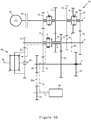
- Figure 7 shows a power transmitting path 84 that the HPDS 110 and the transmission 70 can provide for a fifth forward speed ratio while operating in the PEDM.
- the power transmitting path 84 can be achieved when (i) the clutch 40 is in an engaged state such that ICE 30 is coupled to the input shaft 1, (ii) the synchronizer 26 is engaged to the driving gearwheel 12, and (iii) the synchronizer 7 and the synchronizer 9 are in their neutral position.
- Shifting the transmission 70 into this fifth forward speed ratio can include at least one of the following: forcing the synchronizer 7 to move axially into its neutral position, forcing the synchronizer 26 to move axially to engage to the driving gearwheel 12, and forcing the synchronizer 9 to move axially into its neutral position.
- the power output by the ICE 30 is transmitted in sequence through the driving gearwheel 12 on the input shaft 1, the driven gearwheel 18 on the output shaft 2, the speed-reducing gearwheel 14 on the output shaft 2, and the final driven gearwheel 25 on the differential 60.
- the power transmitted to the final driven gearwheel 25 can be output by at least one of the half-axles 6a and 6b and to a respective wheel connectable thereto.
- Figure 8 shows a power transmitting path 85 that the HPDS 110 and the transmission 70 can provide for a sixth forward speed ratio while operating in the PEDM.
- the power transmitting path 85 can be achieved when (i) the clutch 40 is in an engaged state such that ICE 30 is coupled to the input shaft 1, (ii) the synchronizer 7 is engaged to the driving gearwheel 10, (iii) the synchronizer 26 is in its neutral position, and (iv) the synchronizer 9 is engaged to the driven gearwheel 16.
- Shifting the transmission 70 into this sixth forward speed ratio can include at least one of the following: forcing the synchronizer 7 to move axially to engage to the driving gearwheel 10, forcing the synchronizer 26 to move axially into its neutral position, and forcing the synchronizer 9 to engage to the driven gearwheel 16.
- the power output by the ICE 30 is transmitted in sequence through the driving gearwheel 10 on the input shaft 1, the driven gearwheel 15 on the output shaft 2, the driven gearwheel 21 on the intermediate shaft 3, the driven gearwheel 22 on the intermediate shaft 3, the driven gearwheel 17 on the intermediate shaft 5, the speed-reducing gearwheel 14 on the output shaft 2, and the final driven gearwheel 25 on the differential 60.
- the power transmitted to the final driven gearwheel 25 can be output by at least one of the half-axles 6a and 6b and to a respective wheel connectable thereto.
- Figure 9 shows a power transmitting path 86 that the HPDS 110 and the transmission 70 can provide for a reverse speed ratio while operating in the PEDM.
- the power transmitting path 86 can be achieved when (i) the clutch 40 is in an engaged state such that ICE 30 is coupled to the input shaft 1, (ii) the synchronizer 7 is in its neutral position, (iii) the synchronizer 26 is in its neutral position, (iv) the synchronizer 9 is engaged to the driven gearwheel 15, and (v) the driven gearwheel 23 is engaged to the driving gearwheel 8.
- Shifting the transmission 70 for this reverse speed ratio can include at least one of the following: forcing the synchronizer 7 to move axially into its neutral position, forcing the synchronizer 26 to move axially into its neutral position, forcing the synchronizer 9 to move axially to engage to the driven gearwheel 15, and forcing the driven gearwheel 23 to move axially to engage to the driving gearwheel 8.
- the power output by the ICE 30 is transmitted in sequence through the driving gearwheel 8 on the synchronizer 26, the driven gearwheel 23 on the intermediate shaft 2, the driven gearwheel 21 on the intermediate shaft 2, the driven gearwheel 15 on the output shaft 2, the speed-reducing gearwheel 14 on the output shaft 2, and the final driven gearwheel 25 on the differential 60.
- the power transmitted to the final driven gearwheel 25 can be output by at least one of the half-axles 6a and 6b and to a respective wheel connectable thereto.
- Figure 10 shows a power transmitting path 87 that the HPDS 110 and the transmission 70 can provide for a first forward speed ratio while operating in the PMDM.
- the power transmitting path 87 can be achieved when (i) the synchronizer 7 and the synchronizer 26 are in their neutral position, and (ii) the synchronizer 9 is engaged to the driven gearwheel 15.
- the clutch 40 can be disengaged such that the ICE 30 is not coupled to the input shaft 1 or the ICE 30 is not outputting power. Shifting the transmission 70 into this first forward speed ratio can include at least one of the following: forcing the synchronizer 7 to move axially into its neutral position, forcing the synchronizer 26 to move axially into its neutral position, and forcing the synchronizer 9 to engage to the driven gearwheel 15.
- the power output by the EM 50 is transmitted in sequence through the driving gearwheel 24 on the motor shaft 4, the driven gearwheel 20 on the intermediate shaft 3, the driven gearwheel 21 on the intermediate shaft 3, the driven gearwheel 15 on the output shaft 2, the speed-reducing gearwheel 14 on the output shaft 2, and the final driven gearwheel 25 on the differential 60.
- the power transmitted to the final driven gearwheel 25 can be output by at least one of the half-axles 6a and 6b and to a respective wheel connectable thereto.
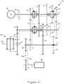
- Figure 11 shows a power transmitting path 88 that the HPDS 110 and the transmission 70 can provide for a second forward speed ratio while operating in the PMDM.
- the power transmitting path 88 can be achieved when (i) the synchronizer 7 is engaged to the driving gearwheel 10, (ii) the synchronizer 26 is engaged to the driving gearwheel 13, and (iii) the synchronizer 9 is in its neutral position.
- the clutch 40 can be disengaged such that the ICE 30 is not coupled to the input shaft 1 or the ICE 30 is not outputting power.
- Shifting the transmission 70 into this second forward speed ratio can include at least one of the following: forcing the synchronizer 7 to move axially to engage to the driving gearwheel 10, forcing the synchronizer 26 to move axially to engage to the driving gearwheel 13, and forcing the synchronizer 9 to move axially into its neutral position.
- the power output by the EM 50 is transmitted in sequence through the driving gearwheel 24 on the motor shaft 4, the driven gearwheel 20 on the intermediate shaft 3, the driven gearwheel 21 on the intermediate shaft 3, the driven gearwheel 15 on the output shaft 2, the driving gearwheel 10, the driving gearwheel 13 on the input shaft 1, the driven gearwheel 19 on the output shaft 2, the speed-reducing gearwheel 14 on the output shaft 2, and the final driven gearwheel 25 on the differential 60.
- the power transmitted to the final driven gearwheel 25 can be output by at least one of the half-axles 6a and 6b and to a respective wheel connectable thereto.
- Figure 12 shows a power transmitting path 89 that the HPDS 110 and the transmission 70 can provide for a third forward speed ratio while operating in the PMDM.
- the power transmitting path 89 can be achieved when (i) the synchronizer 7 is engaged to the driving gearwheel 11, (ii) the synchronizer 26 is engaged to the driving gearwheel 13, and (iii) the synchronizer 9 is in its neutral position.
- the clutch 40 can be disengaged such that the ICE 30 is not coupled to the input shaft 1 or the ICE 30 is not outputting power.
- Shifting the transmission 70 into this third forward speed ratio can include at least one of the following: forcing the synchronizer 7 to move axially to engage to the driving gearwheel 11, forcing the synchronizer 26 to move axially to engage to the driving gearwheel 13, and forcing the synchronizer 9 to move axially into its neutral position.
- the power output by the EM 50 is transmitted in sequence through the driving gearwheel 24 on the motor shaft 4, the driven gearwheel 20 on the intermediate shaft 3, the driven gearwheel 22 on the intermediate shaft 3, the driven gearwheel 17 and the driven gearwheel 16 on the intermediate shaft 5, the driving gearwheel 11 on the input shaft 1, the driving gearwheel 13 on the input shaft 1, the driven gearwheel 19 on the output shaft 2, the speed-reducing gearwheel 14 on the output shaft 2, and the final driven gearwheel 25 on the differential 60.
- the power transmitted to the final driven gearwheel 25 can be output by at least one of the half-axles 6a and 6b and to a respective wheel connectable thereto.
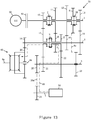
- Figure 13 shows a power transmitting path 90 that the HPDS 110 and the transmission 70 can provide for a fourth forward speed ratio while operating in the PMDM.
- the power transmitting path 90 can be achieved when (i) the synchronizer 7 and the synchronizer 26 are in their neutral position, and (ii) the synchronizer 9 is engaged to the driven gearwheel 16.
- the clutch 40 can be disengaged such that the ICE 30 is not coupled to the input shaft 1 or the ICE 30 is not outputting power. Shifting the transmission 70 into this fourth forward speed ratio can include at least one of the following: forcing the synchronizer 7 to move axially into its neutral position, forcing the synchronizer 26 to move axially into its neutral position, and forcing the synchronizer 9 to engage to the driven gearwheel 16.
- the power output by the EM 50 is transmitted in sequence through the driving gearwheel 24 on the motor shaft 4, the driven gearwheel 20 on the intermediate shaft 3, the driven gearwheel 22 on the intermediate shaft 3, the driven gearwheel 17 on the intermediate shaft 5, the speed-reducing gearwheel 14 on the output shaft 2, and the final driven gearwheel 25 on the differential 60.
- the power transmitted to the final driven gearwheel 25 can be output by at least one of the half-axles 6a and 6b and to a respective wheel connectable thereto..
- Figure 14 shows a power transmitting path 91 that the HPDS 110 and the transmission 70 can provide for a first forward speed ratio while operating in the HDM.
- the power transmitting path 91 can be achieved when (i) the clutch 40 is in an engaged state such that ICE 30 is coupled to the input shaft 1, (ii) the synchronizer 7 is engaged to the driving gearwheel 11, (iii) the synchronizer 26 is in its neutral position, and (iv) the synchronizer 9 is engaged to the driven gearwheel 15.
- Shifting the transmission 70 into this first forward speed ratio can include at least one of the following: forcing the synchronizer 7 to move axially to engage to the driving gearwheel 11, forcing the synchronizer 26 to move axially into its neutral position, and forcing the synchronizer 9 to engage to the driven gearwheel 15.
- the power output by the ICE 30 is transmitted in sequence through the driving gearwheel 11 on the input shaft 1, the driven gearwheel 16 on the output shaft 2, the driven gearwheel 17 on the intermediate shaft 5, the driven gearwheel 22 on the intermediate shaft 3, the driven gearwheel 21 on the intermediate shaft 3, the driven gearwheel 15 on the output shaft 2, the speed-reducing gearwheel 14 on the output shaft 2, and the final driven gearwheel 25 on the differential 60.
- the power output by the EM 50 is transmitted in sequence through the driving gearwheel 24 on the motor shaft 4, the driven gearwheel 20 on the intermediate shaft 3, the driven gearwheel 21 on the intermediate shaft 3, the driven gearwheel 15 on the output shaft 2, the speed-reducing gearwheel 14 on the output shaft 2, and the final driven gearwheel 25 on the differential 60.
- the power transmitted to the final driven gearwheel 25 from the ICE 30 and the EM 50 can be output by at least one of the half-axles 6a and 6b and to a respective wheel connectable thereto.
- the power transmitting path for power from the ICE 30 follows the power transmitting path 80 and the power from the EM 50 follows the power transmitting path 87.
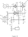
- Figure 15 shows a power transmitting path 91 that the HPDS 110 and the transmission 70 can provide for a second forward speed ratio while operating in the HDM.
- the power transmitting path 92 can be achieved when (i) the clutch 40 is in an engaged state such that ICE 30 is coupled to the input shaft 1, (ii) the synchronizer 7 is engaged to the driving gearwheel 10, (iii) the synchronizer 26 is in its neutral position, and (iv) the synchronizer 9 on the output shaft 2 is engaged to the driven gearwheel 15.
- Shifting the transmission 70 into this second forward speed ratio can include at least one of the following: forcing the synchronizer 7 to move axially to engage to the driving gearwheel 10, forcing the synchronizer 26 to move axially into its neutral position, and forcing the synchronizer 9 to move axially to engage to the driven gearwheel 15.
- the power output by the ICE 30 is transmitted in sequence through the driving gearwheel 10 on the input shaft 1, the driven gearwheel 15 on the output shaft 2, the speed-reducing gearwheel 14 on the output shaft 2, and the final driven gearwheel 25 on the differential 60.
- the power output by the EM 50 is transmitted in sequence through the driving gearwheel 24 on the motor shaft 4, the driven gearwheel 20 on the intermediate shaft 3, the driven gearwheel 21 on the intermediate shaft 3, the driven gearwheel 15 on the output shaft 2, the speed-reducing gearwheel 14 on the output shaft 2, and the final driven gearwheel 25 on the differential 60.
- the power transmitted to the final driven gearwheel 25 from the ICE 30 and the EM 50 can be output by at least one of the half-axles 6a and 6b and to a respective wheel connectable thereto.
- the power transmitting path for power from the ICE 30 follows the power transmitting path 81 and the power from the EM 50 follows the power transmitting path 87.
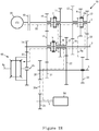
- Figure 16 shows a power transmitting path 93 that the HPDS 110 and the transmission 70 can provide for a first instance of a third forward speed ratio while operating in the HDM.
- the power transmitting path 93 can be achieved when (i) the clutch 40 is in an engaged state such that ICE 30 is coupled to the input shaft 1, (ii) the synchronizer 7 is in its neutral position, (iii) the synchronizer 26 is engaged to the driving gearwheel 13, and (iv) the synchronizer 9 is engaged to the driven gearwheel 15.
- Shifting the transmission 70 into this third forward speed ratio can include at least one of the following: forcing the synchronizer 7 to move axially into its neutral position, forcing the synchronizer 26 to move axially to engage to the driving gearwheel 13, and forcing the synchronizer 9 to move axially to engage to the driven gearwheel 15.
- the power output by the ICE 30 is transmitted in sequence through the driving gearwheel 13 on the input shaft 1, the driven gearwheel 19 on the output shaft 2, the speed-reducing gearwheel 14 on the output shaft 2, and the final driven gearwheel 25 on the differential 60.
- the power output by the EM 50 is transmitted in sequence through the driving gearwheel 24 on the motor shaft 4, the driven gearwheel 20 on the intermediate shaft 3, the driven gearwheel 21 on the intermediate shaft 3, the driven gearwheel 15 on the output shaft 2, the speed-reducing gearwheel 14 on the output shaft 2, and the final driven gearwheel 25 on the differential 60.
- the power transmitted to the final driven gearwheel 25 from the ICE 30 and the EM 50 can be output by at least one of the half-axles 6a and 6b and to a respective wheel connectable thereto.
- the power transmitting path for power from the ICE 30 follows the power transmitting path 82 and the power from the EM 50 follows the power transmitting path 87.
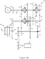
- Figure 17 shows a power transmitting path 94 that the HPDS 110 and the transmission 70 can provide for a second instance of a third forward speed ratio while operating in the HDM.
- the power transmitting path 94 can be achieved when (i) the clutch 40 is in an engaged state such that ICE 30 is coupled to the input shaft 1, (ii) the synchronizer 7 is engaged to the driving gearwheel 10, (iii) the synchronizer 26 is engaged to the driving gearwheel 13, and (iv) the synchronizer 9 is in its neutral position.
- Shifting the transmission 70 into this third forward speed ratio can include at least one of the following: forcing the synchronizer 7 to move axially to engage to the driving gearwheel 10, forcing the synchronizer 26 to move axially to engage to the driving gearwheel 13, and forcing the synchronizer 9 to move axially into its neutral position.
- the power output by the ICE 30 is transmitted in sequence through the driving gearwheel 13 on the input shaft 1, the driven gearwheel 19 on the output shaft 2, the speed-reducing gearwheel 14 on the output shaft 2, and the final driven gearwheel 25 on the differential 60.
- the power output by the EM 50 is transmitted in sequence through the driving gearwheel 24 on the motor shaft 4, the driven gearwheel 20 on the intermediate shaft 3, the driven gearwheel 21 on the intermediate shaft 3, the driven gearwheel 15 on the output shaft 2, the driving gearwheel 10 on the input shaft 1, the driving gearwheel 13 on the input shaft 1, the driven gearwheel 19 on the output shaft 2, the speed-reducing gearwheel 14 on the output shaft 2, and the final driven gearwheel 25 on the differential 60.
- the power transmitted to the final driven gearwheel 25 from the ICE 30 and the EM 50 can be output by at least one of the half-axles 6a and 6b and to a respective wheel connectable thereto.
- the power transmitting path for power from the ICE 30 follows the power transmitting path 82 and the power from the EM 50 follows the power transmitting path 88.
- Figure 18 shows a power transmitting path 95 that the HPDS 110 and the transmission 70 can provide for a third instance of a third forward speed ratio while operating in the HDM.
- the power transmitting path 95 can be achieved when (i) the clutch 40 is in an engaged state such that ICE 30 is coupled to the input shaft 1, (ii) the synchronizer 7 is engaged to the driving gearwheel 11, (iii) the synchronizer 26 is engaged to the driving gearwheel 13, and (iv) the synchronizer 9 is in its engaged position.
- Shifting the transmission 70 into this third forward speed ratio can include at least one of the following: forcing the synchronizer 7 to move axially to engage to the driving gearwheel 11, forcing the synchronizer 26 to move axially to engage to the driving gearwheel 13, and forcing the synchronizer 9 to move axially into its neutral position.
- the power output by the ICE 30 is transmitted in sequence through the driving gearwheel 13 on the input shaft 1, the driven gearwheel 19 on the output shaft 2, the speed-reducing gearwheel 14 on the output shaft 2, and the final driven gearwheel 25 on the differential 60.
- the power output by the EM 50 is transmitted in sequence through the driving gearwheel 24 on the motor shaft 4, the driven gearwheel 20 on the intermediate shaft 3, the driven gearwheel 22 on the intermediate shaft 3, the driven gearwheel 17 and the driven gearwheel 16 on the intermediate shaft 5, the driving gearwheel 11 on the input shaft 1, the driving gearwheel 13 on the input shaft 1, the driven gearwheel 19 on the output shaft 2, the speed-reducing gearwheel 14 on the output shaft 2, and the final driven gearwheel 25 on the differential 60.
- the power transmitted to the final driven gearwheel 25 from the ICE 30 and the EM 50 can be output by at least one of the half-axles 6a and 6b and to a respective wheel connectable thereto.
- the power transmitting path for power from the ICE 30 follows the power transmitting path 82 and the power from the EM 50 follows the power transmitting path 89.
- Figure 19 shows a power transmitting path 96 that the HPDS 110 and the transmission 70 can provide for a fourth instance of a third forward speed ratio while operating in the HDM.
- the power transmitting path 96 can be achieved when (i) the clutch 40 is in an engaged state such that ICE 30 is coupled to the input shaft 1, (ii) the synchronizer 7 is in its neutral position, (iii) the synchronizer 26 is engaged to the driving gearwheel 13, and (iv) the synchronizer 9 is engaged to the driven gearwheel 16.
- Shifting the transmission 70 into this third forward speed ratio can include at least one of the following: forcing the synchronizer 7 to move axially into its neutral position, forcing the synchronizer 26 to move axially to engage to the driving gearwheel 13, and forcing the synchronizer 9 to move axially to engage to the driven gearwheel 16.
- the power output by the ICE 30 is transmitted in sequence through the driving gearwheel 13 on the input shaft 1, the driven gearwheel 19 on the output shaft 2, the speed-reducing gearwheel 14 on the output shaft 2, and the final driven gearwheel 25 on the differential 60.
- the power output by the EM 50 is transmitted in sequence through the driving gearwheel 24 on the motor shaft 4, the driven gearwheel 20 on the intermediate shaft 3, the driven gearwheel 22 on the intermediate shaft 3, the driven gearwheel 17 on the intermediate shaft 5, the speed-reducing gearwheel 14 on the output shaft 2, and the final driven gearwheel 25 on the differential 60.
- the power transmitted to the final driven gearwheel 25 from the ICE 30 and the EM 50 can be output by at least one of the half-axles 6a and 6b and to a respective wheel connectable thereto.
- the power transmitting path for power from the ICE 30 follows the power transmitting path 82 and the power from the EM 50 follows the power transmitting path 90.
- Figure 20 shows a power transmitting path 97 that the HPDS 110 and the transmission 70 can provide for a fourth forward speed ratio while operating in the HDM.
- the power transmitting path 97 can be achieved when (i) the clutch 40 is in an engaged state such that ICE 30 is coupled to the input shaft 1, (ii) the synchronizer 7 is engaged to the driving gearwheel 11, (iii) the synchronizer 26 is in its neutral position, and (iv) the synchronizer 9 is engaged to the driven gearwheel 16.
- Shifting the transmission 70 into this fourth forward speed ratio can include at least one of the following: forcing the synchronizer 7 to move axially to engage to the driving gearwheel 11, forcing the synchronizer 26 to move axially into its neutral position, and forcing the synchronizer 9 to move axially to engage to the driven gearwheel 16.
- the power output by the ICE 30 is transmitted in sequence through the driving gearwheel 11 on the input shaft 1, the driven gearwheel 16 on the intermediate shaft 5, the speed-reducing gearwheel 14 on the output shaft 2, and the final driven gearwheel 25 on the differential 60.
- the power output by the EM 50 is transmitted in sequence through the driving gearwheel 24 on the motor shaft 4, the driven gearwheel 20 on the intermediate shaft 3, the driven gearwheel 22 on the intermediate shaft 3, the driven gearwheel 17 on the intermediate shaft 5, the speed-reducing gearwheel 14 on the output shaft 2, and the final driven gearwheel 25 on the differential 60.
- the power transmitted to the final driven gearwheel 25 from the ICE 30 and the EM 50 can be output by at least one of the half-axles 6a and 6b and to a respective wheel connectable thereto.
- the power transmitting path for power from the ICE 30 follows the power transmitting path 83 and the power from the EM 50 follows the power transmitting path 90.
- Figure 21 shows a power transmitting path 98 that the HPDS 110 and the transmission 70 can provide for a firth forward speed ratio while operating in the HDM.
- the power transmitting path 98 can be achieved when (i) the clutch 40 is in an engaged state such that ICE 30 is coupled to the input shaft 1, (ii) the synchronizer 7 is in its neutral position, (iii) the synchronizer 26 is engaged to the driving gearwheel 12, and (iv) the synchronizer 9 is engaged to the driven gearwheel 16.
- Shifting the transmission 70 into this fifth forward speed ratio can include at least one of the following: forcing the synchronizer 7 to move axially into its neutral position, forcing the synchronizer 26 to move axially to engage to the driving gearwheel 12, and forcing the synchronizer 9 to move axially to engage to the driven gearwheel 16.
- the power output by the ICE 30 is transmitted in sequence through the driving gearwheel 12 on the input shaft 1, the driven gearwheel 18 on the output shaft 2, the speed-reducing gearwheel 14 on the output shaft 2, and the final driven gearwheel 25 on the differential 60.
- the power output by the EM 50 is transmitted in sequence through the driving gearwheel 24 on the motor shaft 4, the driven gearwheel 20 on the intermediate shaft 3, the driven gearwheel 22 on the intermediate shaft 3, the driven gearwheel 17 on the intermediate shaft 5, the speed-reducing gearwheel 14 on the output shaft 2, and the final driven gearwheel 25 on the differential 60.
- the power transmitted to the final driven gearwheel 25 from the ICE 30 and the EM 50 can be output by at least one of the half-axles 6a and 6b and to a respective wheel connectable thereto.
- the power transmitting path for power from the ICE 30 follows the power transmitting path 84 and the power from the EM 50 follows the power transmitting path 90.
- Figure 22 shows a power transmitting path 99 that the HPDS 110 and the transmission 70 can provide for a sixth forward speed ratio while operating in the HDM.
- the power transmitting path 99 can be achieved when (i) the clutch 40 is in an engaged state such that ICE 30 is coupled to the input shaft 1, (ii) the synchronizer 7 is engaged to the driving gearwheel 10, (iii) the synchronizer 26 is in its neutral position, and (iv) the synchronizer 9 is engaged to the driven gearwheel 16.
- Shifting the transmission 70 into this sixth forward speed ratio can include at least one of the following: forcing the synchronizer 7 to move axially to engage to the driving gearwheel 10, forcing the synchronizer 26 to move axially into its neutral position, and forcing the synchronizer 9 to move axially to engage to the driven gearwheel 16.
- the power output by the ICE 30 is transmitted in sequence through the driving gearwheel 10 on the input shaft 1, the driven gearwheel 15 on the output shaft 2, the driven gearwheel 21 on the intermediate shaft 3, the driven gearwheel 22 on the intermediate shaft 3, the driven gearwheel 17 on the intermediate shaft 5, the speed-reducing gearwheel 14 on the output shaft 2, and the final driven gearwheel 25 on the differential 60.
- the power output by the EM 50 is transmitted in sequence through the driving gearwheel 24 on the motor shaft 4, the driven gearwheel 20 on the intermediate shaft 3, the driven gearwheel 22 on the intermediate shaft 3, the driven gearwheel 17 on the intermediate shaft 5, the speed-reducing gearwheel 14 on the output shaft 2, and the final driven gearwheel 25 on the differential 60.
- the power transmitted to the final driven gearwheel 25 from the ICE 30 and the EM 50 can be output by at least one of the half-axles 6a and 6b and to a respective wheel connectable thereto.
- the power transmitting path for power from the ICE 30 follows the power transmitting path 85 and the power from the EM 50 follows the power transmitting path 90.
- Figure 23 shows a power transmitting path 100 that the HPDS 110 and the transmission 70 can provide for a reverse speed ratio while operating in the HDM.
- the power transmitting path 100 can be achieved when (i) the clutch 40 is in an engaged state such that ICE 30 is coupled to the input shaft 1, (ii) the synchronizer 7 and the synchronizer 26 is in their neutral position, (iii) the synchronizer 9 is engaged to the driven gearwheel 15, and (iv) the driven gearwheel 23 is engaged to the driving gearwheel 8.
- Shifting the transmission 70 for this reverse speed ratio can include at least one of the following: forcing the synchronizer 7 to move axially into its neutral position, forcing the synchronizer 26 to move axially into its neutral position, forcing the synchronizer 9 to move axially to engage to the driven gearwheel 15, and forcing the driven gearwheel 23 to move axially to engage to the driving gearwheel 8.
- the power output by the ICE 30 is transmitted in sequence through the driving gearwheel 8 on the synchronizer 26, the driven gearwheel 23 on the intermediate shaft 3, the driven gearwheel 21 on the intermediate shaft 3, the driven gearwheel 15 on the output shaft 2, the speed-reducing gearwheel 14 on the output shaft 2, and the final driven gearwheel 25 on the differential 60.
- the power output by the EM 50 is transmitted in sequence through the driving gearwheel 24 on the motor shaft 4, the driven gearwheel 20 on the intermediate shaft 3, the driven gearwheel 21 on the intermediate shaft 3, the driven gearwheel 15 on the output shaft 2, the speed-reducing gearwheel 14 on the output shaft 2, and the final driven gearwheel 25 on the differential 60.
- the power transmitted to the final driven gearwheel 25 from the ICE 30 and the EM 50 can be output by at least one of the half-axles 6a and 6b and to a respective wheel connectable thereto.
- the power transmitting path for power from the ICE 30 follows the power transmitting path 86 and the power from the EM 50 follows the power transmitting path 87 with the EM 50 turning in a direction opposite the direction the EM turns for the first forward speed ration in the PMDM.
- the HPDS 110 and the transmission 70 can provide for gear shifting without power interruption for the HDM.
- Table 3 includes data showing an example sequence of shifting that can occur without power interruption.
- the power transmitting path identifiers 91-99 are shown in the first column with ICE# and EM#, where # equals a forward speed ratio. Referring to the orientation of the synchronizers 7, 9, and 26 in figure 1 , the synchronizers can be moved axially to the left or to the right.
- X represents the left, neutral, or right position of a synchronizer. In any two adjacent rows in Table 3, at least one synchronizer remains in the same left or right position.
- the shifting without power interruption can occur in a direction from power transmitting path 91 to power transmitting path 99 or in a direction from power transmitting path 99 to power transmitting path 91. Moreover, the shifting without power interruption can occur in any of those directions with as few as two of the adjacent power transmitting paths.
Landscapes
- Engineering & Computer Science (AREA)
- Mechanical Engineering (AREA)
- Chemical & Material Sciences (AREA)
- Combustion & Propulsion (AREA)
- Transportation (AREA)
- General Engineering & Computer Science (AREA)
- Structure Of Transmissions (AREA)
- Hybrid Electric Vehicles (AREA)
- Gear Transmission (AREA)
- Electric Propulsion And Braking For Vehicles (AREA)
- Shafts, Cranks, Connecting Bars, And Related Bearings (AREA)
Description
- Unless otherwise indicated herein, the elements described in this section, the technical field, and the background art are not prior art to the claims and are not admitted to be prior art by inclusion in this section.
- This invention relates to a hybrid-power driving system (HPDS) in which six forward speed ratios are available by switching only three synchronizers. A HPDS includes synchronizers that are cooperatively switched and gearwheels that are shared in different gear ratios (i.e., speed ratios), an electric motor (or more simply, "EM"), and an internal combustion engine (or more simply, "engine" or "ICE").
- As the pollution of the environment, the demand for petroleum, and the requirements for vehicle emission equipment increase, vehicles with new power sources get more and more attention. Hybrid-power vehicles are widely used, at least in part, because of their low operating cost and low emissions. In known hybrid-power vehicles, the ICE, the clutch, the EM, and the transmission are disposed in sequence and occupy a large space in a vehicle. Deploying those hybrid-power vehicle components in such a layout can result in limiting the size of the EM, and as a result, limiting the power of the EM and the power capacity of the vehicle. As such, the fuel use efficiency cannot be improved significantly with respect to non-hybrid vehicles. Furthermore, the driving ability in a pure motor driving mode is not satisfying when the power of the EM is too low.
- Furthermore still, in current vehicle hybrid-power driving systems, driving comfort cannot be ensured since power interruption cannot be avoided automatically in the configuration having a single clutch. In a known vehicle hybrid-power driving system, the EM and the ICE have their corresponding power transmitting mechanisms that are disposed in parallel and function cooperatively, which results in a vehicle hybrid power driving system having complex power transmitting paths.
-
DE 10 2009 023499 discloses a method for operating a hybrid drive system involving coupling an input shaft with a main drive machine, where another input shaft is drivingly coupled with an additional drive machine. The method provides eight displayable gear change positions for the main drive machine for forward motion, seven displayable gear change positions for the additional drive machine for forward drive, and ten different gear change positions are represented in the hybrid drive mode for forward drive. - The invention is defined in the attached independent claim to which reference should now be made. Further, optional features may be found in the sub-claims appended thereto.
- In accordance with the invention, there is provided an HPDS in which six forward speed ratios are available by switching only three synchronizers comprising: (i) an input shaft carrying a first driving gearwheel, a second driving gearwheel, a third driving gearwheel, and a fourth driving gearwheel disposed thereon, (ii) a first synchronizer, disposed on the input shaft, for releasably synchronizing at least one of the first driving gearwheel and the second driving gearwheel to the input shaft, (iii) a second synchronizer, disposed on the input shaft, for releasably synchronizing at least one of the third driving gearwheel and the fourth driving gearwheel to the input shaft, (iv) an output shaft carrying a speed-reducing gearwheel, a first driven gearwheel, a second driven gearwheel, and a third driven gearwheel disposed thereon, (v) a first intermediate shaft carrying a fourth driven gearwheel and a fifth driven gearwheel disposed thereon, wherein the first intermediate shaft includes a hollow portion and is coaxial to the output shaft, (vi) a third synchronizer, disposed on the output shaft, for releasably synchronizing at least one of the first driven gearwheel and both the fourth driven gearwheel and the fifth driven gearwheel to the output shaft, (vii) a second intermediate shaft carrying a sixth driven gearwheel, a seventh driven gearwheel, an eighth driven gearwheel, and a ninth driven gearwheel disposed thereon, (viii) a motor shaft carrying a fifth driving gearwheel disposed thereon, (ix) a final driven gearwheel and (x) a sixth driving gearwheel carried by the input shaft, wherein the ninth driven gearwheel is slidable to releasably mesh with the sixth driving gearwheel. The sixth driving gearwheel is disposed on the second synchronizer.
- These as well as other aspects and advantages will become apparent to those of ordinary skill in the art by reading the following detailed description, with reference where appropriate to the accompanying drawings. Further, it should be understood that the embodiments described in this overview and elsewhere are intended to be examples only and do not necessarily limit the scope of the invention.
- Example embodiments are described herein with reference to the drawings.
-
Figure 1 is a schematic view of an HPDS in accordance with the example embodiments. -
Figure 2 is a schematic view of the structure of motor drives in accordance with the example embodiments. -
Figures 3-23 are schematic views showing power transmitting paths of the HPDS offigure 1 . - This description describes several example embodiments. The example embodiments can be applicable to an HPDS and components of or usable in an HPDS or usable in another type of driving system. A driving system, such as an HPDS or otherwise, can be installed within a vehicle such as, but not limited to, an automobile or a truck. An HPDS installed or installable within a vehicle can be referred to as a vehicle HPDS. Each example embodiment described herein can be a vehicle HPDS or a portion thereof, but is not so limited.
- The example embodiments can provide for an HPDS that can provide a pure engine driving mode (PEDM), a pure motor driving mode (PMDM), and a hybrid-power driving mode (HDM). At least one of the power capacity and fuel efficiency of a vehicle can be improved significantly by use of at least one of the example embodiments. The HPDS can include synchronizers that are cooperatively switched and gearwheels that are used in multiple speed ratios. This can provide for a compact structure of the transmission or gearbox and effective cooperation of an EM and an ICE in multiple speed ratios can be achieved. The HPDS can include a single clutch and gear shifting can be conducted without power interruption. Furthermore, power interruption during gear shifting can be avoided by alternate operation of the EM and the ICE. Stated another way, the transmission of the example HPDS with a single clutch can output power continuously while the gearwheels of the transmission are shifted such that the transmission outputs power continuously prior to, during, and after shifting of the transmission gearwheels.
- In accordance with the example embodiments, an HPDS can include a transmission or gearbox having common gears that are shared in different speed ratios. The benefits of such a system include, but are not limited to, a reduced number of transmission components, a more compact structure, and a lower cost to produce the system. The transmission can be coupled to an ICE operable in the PEDM and the HDM and to an EM operable in the PMDM and the HDM.
- In accordance with the example embodiments, the EM can provide four forward speed ratios. In this manner, the speed of the EM can be kept relatively low so that the EM can operate at higher efficiency levels. The ICE can operate under at least six forward speed ratios so that the operation efficiency of the ICE is high.
- The example embodiments can include a single clutch transmission and a three synchronizer gearbox or transmission that provides for at least six forward speed ratios. The clutch can allow for shifting of gears without interrupting the transmission of power through the transmission and HPDS. A person having ordinary skill in the art will understand that the described example embodiments allow for a more compact HPDS arrangement as compared to an HPDS arrangement having at least one of (i) two or more clutches, and (ii) four or more synchronizers.
- Within this description, the articles "a," "an," and "the" are used to introduce elements of the example embodiments. The intent of using those articles is that there is one or more of the elements. The intent of using the conjunction "or" within a list of at least two terms in this description is to indicate any of the listed terms or any combination of the listed terms. For example, in a list of terms recited as "A, B, or C," the combinations indicated by that list of terms include any one or more of "A and B," "A and C," "B, and C," and "A, B, and C." The use of ordinal numbers such as "first," "second," "third," and so on in the description is to distinguish respective elements rather than to denote a particular order of those elements unless the context of using those terms explicitly indicates otherwise.
- The diagrams and power transmission paths shown in the figures are provided merely as examples and are not intended to be limiting. Those skilled in the art will appreciate that other arrangements of the elements shown in the figures can be used instead.
-
Figure 1 is a schematic view of an HPDS 110 in accordance with multiple example embodiments. In accordance with an example embodiment, the HPDS 110 includes atransmission 70. In accordance with another example embodiment, the HPDS 110 can include thetransmission 70 and at least one of an ICE 30 and anEM 50. The EM 50 can rotate amotor shaft 4 of thetransmission 70. Themotor shaft 4 can, in turn, rotate amechanical compressor 55 of an air conditioning system or acompressor clutch 57 thereof, but the motor shaft is not so limited. Themotor shaft 4 can include splines for engaging a rotor (not shown) of theEM 50 and adriving gearwheel 24 on themotor shaft 4. HPDS 110 can be installed within a vehicle, such that HPDS 110 is a vehicle HPDS. - The
ICE 30 and theEM 50 can each output power. The power (P) output by theICE 30 can be calculated using the relationship TICE x WICE, where TICE equals the torque at the flywheel of the engine and WICE equals an angular speed of the flywheel. The power (P) output by theEM 50 can be calculated using the relationship TEM x WEM, where TEM equals the torque of a rotor within theEM 50 and WEM equals an angular speed of the rotor. The power output by theICE 30 can be transmitted (e.g., transferred) to a clutch 40 and to an input shaft of thetransmission 70, and, in turn, to wheels of a vehicle. The power output by theEM 50 can be output to the motor shaft of thetransmission 70 and, in turn, to the wheels of the vehicle. The power received by thetransmission 70 from theICE 30 or theEM 50 can be referred to as input power. Since the power transmitted by thetransmission 70 includes a torque aspect, the transmission of power through or by thetransmission 70 can be referred to as the transmission of torque through or by thetransmission 70. - The
transmission 70 includes aninput shaft 1, anoutput shaft 2, anintermediate shaft 3, amotor shaft 4, and anintermediate shaft 5. The five aforementioned shafts are referred to herein as the "five transmission shafts." Theintermediate shaft 5 can include a hollow portion such that theintermediate shaft 5 can be slid onto theoutput shaft 2. Theintermediate shaft 5 can be referred to as a "gear-set shaft," a "hollow shaft," and a "sleeve." Thetransmission 70 can include sleeves (i.e., hollow shafts) 10a, 11a, 12a, 13a, and 15a.Sleeves input shaft 1.Sleeves intermediate shaft 4. - Each of the five transmission shafts can be mounted to, or at least partially within, a transmission case at locations that allow for gearwheels on those transmission shafts to mesh with at least one other gearwheel as described herein. Each of the five transmission shafts can be spatially arranged parallel with each other. The transmission case can form or include a gearbox within which gearwheels of the
transmission 70 and at least a portion of the five transmission shafts are located. TheEM 50 or a portion thereof can be located within the transmission case. Alternatively, theEM 50 can be located outside of the transmission case. - Each of the five transmission shafts can have a first shaft-end-portion and a second shaft-end-portion opposite the first shaft-end-portion axially (e.g., longitudinally). With reference to
figure 1 , the left-most shaft-end-portion of each of the five transmission shafts is referred to as a first shaft-end-portion of that shaft and the right-most shaft-end-portion of each of the five transmission shafts is referred to as a second shaft-end-portion of that shaft. The same designation of shaft-end-portions applies to any transmission shaft described herein or shown in any of the other figures. - The
transmission 70 includes multiple driving gearwheels that drive at least one other gearwheel or causes at least one other gearwheel to turn. A driving gearwheel can be referred to as a "drive gearwheel." Thetransmission 70 includes multiple driven gearwheels. Each driven gearwheel can be driven by another gearwheel (e.g., driven by a driving gearwheel) or by a transmission shaft. One or more of the driving gearwheels described herein can act as a driven gearwheel for at least some of the power transmitting paths. For purposes of this description, the term "gearwheel" can be stated more simply as just "gear." - In an example embodiment of the
HPDS 110 that includes theICE 30, theinput shaft 1 can be coupled to theICE 30 by use of the clutch 40. As an example, the clutch 40 can include a pressure plate assembly, a throw-out bearing, a throw-our fork, and a clutch disk to engage a flywheel of theICE 30, but the clutch 40 is not so limited. The clutch 40 can have an engaged state in which an output of the ICE 30 (e.g., the flywheel) is connected to the input shaft 1 (e.g., by way of the clutch disk). When viewed from a front side of theICE 30 opposite a back side of theICE 30 to which the flywheel is connected, the power or torque output by theICE 30 can turn the clutch 40 in a clockwise direction. Other references herein to theICE 30 or a shaft of thetransmission 70 turning in a clockwise direction are considered from the same viewpoint.Clutch 40 can have a disengaged state in which the output of theICE 30 is not connected to theinput shaft 1. - The
transmission 70 can include a drivinggearwheel 10, asynchronizer 7, a drivinggearwheel 11, a drivinggearwheel 12, asynchronizer 26, and a drivinggearwheel 13 disposed on theinput shaft 1 in a sequence from left to right (e.g., from the first shaft-end-portion to the second shaft-end portion of the input shaft 1) as shown infigure 1 , but are not so limited. For example, those four gearwheels can be in a different sequence between the first shaft-end-portion and the second shaft-end portion of theinput shaft 1 so long as each of those gearwheels is positioned to mesh with the corresponding gearwheel(s) described herein as meshing with that gearwheel. Each of the drivinggearwheel 10, the drivinggearwheel 11, the drivinggearwheel 12, and the drivinggearwheel 13 is configured for engagement to theinput shaft 1 by a synchronizer and is rotatably carried by theinput shaft 1 or is rotatably carried by thesleeves - A gearwheel that is rotatably carried by a shaft is carried by the shaft and can rotate around the shaft (e.g., the gearwheel and the shaft are rotatable with respect to each other) when the gearwheel is not synchronized to the shaft (e.g., disengaged, uncoupled, or unlocked from the shaft). When the rotatably carried gearwheel is synchronized to the shaft by a synchronizer, the gearwheel is not rotatable around the shaft as the gearwheel and shaft are rotatable together.
- In some instances, a gearwheel is fixedly carried by a shaft. A fixedly-carried gearwheel and the shaft which carries the gearwheel rotate together. In some instances, a gearwheel is slidably carried on a shaft. A slidably-carried gearwheel can be slid axially in two opposing directions along the shaft that carries the gearwheel.
- Each synchronizer described herein can include a hub, a synchronizer sleeve, and two blocker rings, but is not so limited. A synchronizer can be configured as a block synchronizer, a cone synchronizer, a pin synchronizer, but is not so limited. Each synchronizer described herein can be moved axially along a shaft on which the synchronizer is disposed and carried. Axial movement of the synchronizer towards a gearwheel adjacent to the synchronizer can lead to synchronizing (i.e., engagement of or coupling of) the gearwheel and the shaft upon which the synchronizer and gearwheel are carried. Axial movement of the synchronizer away from a gearwheel adjacent to the synchronizer can lead to unsynchronizing (i.e., disengagement of or uncoupling of) the gearwheel and the shaft upon which the synchronizer and gearwheel are carried.
- A gearwheel that synchronizes to a shaft by a synchronizer can rotate in the same direction and same speed as the shaft when the gearwheel is synchronized (i.e., engaged, coupled, or locked) to the shaft. Any description herein of a gearwheel being engaged to a synchronizer carried by a transmission shaft includes that gearwheel being engaged to (i.e., synchronized to, coupled to, or locked to) that transmission shaft. A gearwheel that synchronizes to a shaft by a synchronizer can rotate independent of the shaft when the gearwheel and the shaft are not synchronized (i.e., unsynchronized, uncoupled, or unlocked). Instead of using a single synchronizer to synchronize at least two gearwheels, two shafts, or a gear and shaft, separate synchronizers could be used to synchronize the multiple gearwheels or shafts.
- The
synchronizer 7 can be moved axially along theinput shaft 1 by a shift fork or another mechanism. Thesynchronizer 7 can have (i) a first engaged position in which thesynchronizer 7 keeps the drivinggearwheel 10, but not the drivinggearwheel 11, engaged to theinput shaft 1, (ii) a second engaged position in which thesynchronizer 7 keeps the drivinggearwheel 11, but not the drivinggearwheel 10, engaged to thefirst input shaft 1, and (iii) a neutral position in which neither of the drivinggearwheel 10 and the drivinggearwheel 11 is engaged to thefirst input shaft 1. Thesynchronizer 7 can be moved axially along theinput shaft 1 away from a gearwheel adjacent to thesynchronizer 7 so that the gearwheel disengages from theinput shaft 1 and thesynchronizer 7 moves into its neutral position. An "engaged position" can be referred to as a "synchronized position" or a "coupled position." - The
synchronizer 26 can be moved axially along theinput shaft 1 by a shift fork or another mechanism. Thesynchronizer 26 can have (i) a first engaged position in which thesynchronizer 26 keeps the drivinggearwheel 12, but not the drivinggearwheel 13, engaged to theinput shaft 1, (ii) a second engaged position in which thesynchronizer 26 keeps the drivinggearwheel 13, but not the drivinggearwheel 12, engaged to thefirst input shaft 1, and (iii) a neutral position in which neither of the drivinggearwheel 12 and the drivinggearwheel 13 is engaged to thefirst input shaft 1. Thesynchronizer 26 can be moved axially along theinput shaft 1 away from a gearwheel adjacent to thesynchronizer 26 so that the gearwheel disengages from theinput shaft 1 and thesynchronizer 26 moves into its neutral position. Thesynchronizer 26 includes a drivinggearwheel 8. The drivinggearwheel 8 can be disposed on a sliding sleeve of thesynchronizer 26, but is not so limited.Figure 1 illustrates arelative position 8a of drivinggearwheel 8 such that drivengearwheel 23 can be slid to engage to the drivinggearwheel 8. - The
transmission 70 can include a speed-reducinggearwheel 14, a drivengearwheel 15, asynchronizer 9, theintermediate shaft 5, a drivengearwheel 18 and a drivengearwheel 19 disposed on theoutput shaft 2 in a sequence from left to right (e.g., from the first shaft-end-portion to the second shaft-end portion of the output shaft 2) as shown infigure 1 , but are not so limited. For example, those four gearwheels onoutput shaft 2 can be in a different sequence between the first shaft-end-portion and the second shaft-end portion of theoutput shaft 2 so long as each of those gearwheels is positioned to mesh with the corresponding gearwheel(s) described herein as meshing with that gearwheel. - The
synchronizer 9 can be moved axially along theoutput shaft 2 by a shift fork or another mechanism. Thesynchronizer 9 can have (i) a first engaged position in which thesynchronizer 9 keeps the drivengearwheel 15, but not theintermediate shaft 5 and the gearwheels disposed thereon, engaged to theoutput shaft 2, (ii) a second engaged position in which thesynchronizer 9 keeps theintermediate shaft 5 and the gearwheels disposed thereon, but not the drivengearwheel 15, engaged to theoutput shaft 2, and (iii) a neutral position in which neither of the drivengearwheel 15 and theintermediate shaft 5 is engaged to theoutput shaft 2. In this second engaged position, thesynchronizer 9 can engage directly to the drivengearwheel 16 or to theintermediate shaft 5. Thesynchronizer 9 can be moved axially along theoutput shaft 2 away from a gearwheel adjacent to thesynchronizer 9 so that the gearwheel disengages from theoutput shaft 2 and thesynchronizer 9 moves into its neutral position. - The
transmission 70 can include a drivengearwheel 20, a drivengearwheel 21, a drivengearwheel 22, and a drivengearwheel 23 disposed on theintermediate shaft 3. Those four gearwheels can be disposed on theintermediate shaft 3 in a sequence from left to right (e.g., from the first shaft-end-portion to the second shaft-end portion) of theintermediate shaft 3 as shown infigure 1 , but are not so limited. For example, those four gearwheels can be in a different sequence between the first shaft-end-portion and the second shaft-end portion of theintermediate shaft 3 so long as each of those gearwheels is positioned to mesh with the corresponding gearwheel(s) described herein as meshing with that gearwheel. Drivengearwheel 23 can be carried by asleeve 31 that is disposed on and slidable axially along theintermediate shaft 3. - The
transmission 70 can include a drivengearwheel 16 and a drivengearwheel 17 disposed on theintermediate shaft 5 in a sequence from left to right (e.g., from the first shaft-end-portion to the second shaft-end portion) of theintermediate shaft 5 as shown infigure 1 , but are not so limited. For example, those two gearwheels onintermediate shaft 5 can be in a different sequence between the first shaft-end-portion and the second shaft-end portion of theintermediate shaft 5 so long as each of those gearwheels is positioned to mesh with the corresponding gearwheel(s) described herein as meshing with that gearwheel. - The
transmission 70 can include a drivinggearwheel 24 disposed on themotor shaft 4.Compressor 55 can be releasably coupled to themotor shaft 4 byclutch 57. - The
transmission 70 can include a differential 60. The differential 60 can include a final drivengearwheel 25 and differential half-axles (output shafts) 6a and 6b. The differential 60 can include a pair ofcarriers gearwheel 25, ashaft 63 rotatably carried by the pair ofcarriers first gearwheels shaft 63, a pair ofsecond gearwheels first gearwheels axles second gearwheels axles 6 can be connected to vehicle wheels. The pair ofcarriers gearwheel 25, but is not so limited. Each of thefirst gearwheels second gearwheels gearwheel 25, as well as one or more other components of the differential 60, can be carried by or within the differential case. - The
transmission 70 can include amotor drive 20a for transferring power to or from theEM 50. As shown infigure 2a , themotor drive 20a can be arranged as a gear set for transmitting power or torque from drivinggearwheel 24 to drivengearwheel 20. That gear set includes a drivengearwheel 28 and a drivengearwheel 29, but is not so limited. Alternatively, as shown infigure 2b , themotor drive 20a can be arranged as a belt orchain 32 and a belt pulley or sprocket 33 and a belt pulley orsprocket 34 are substituted for driven gearwheel 20 and drivinggearwheel 24, respectively. - The aforementioned gearwheels and synchronizers can be referred to by alternative names. Table 1 shows alternative gearwheel and synchronizer names for the gearwheels and synchronizers of the
transmission 70. Other examples of alternative names are also possible. Table 1 also identifies gearwheels that mesh with other gearwheels of thetransmission 70.Table 1 Gearwheel / Synchronizer (Drawing Reference Number) Alternative names for Gearwheel / Synchronizer Meshing Gearwheels Synchronizer (7) Second-and-fourth-speed-ratio synchronizer 10, 11 Driving gearwheel (8) Gearwheel 23 (Slidable) Synchronizer (9) Synchronizer 15, 16 Driving gearwheel (10) Second-speed-ratio driving gearwheel 15 Driving gearwheel (11) Fourth-speed-ratio driving gearwheel 16 Driving gearwheel (12) Fifth-speed-ratio driving gearwheel 18 Driving gearwheel (13) Third-speed-ratio driving gearwheel 19 Speed-reducing gearwheel (14) Speed-reducing gearwheel 25 Driven gearwheel (15) Second- speed-ratio driven gearwheel 10, 21 Driven gearwheel (16) Fourth-speed-ratio driven gearwheel 11 Driven gearwheel (17) Gearwheel 22 Driven gearwheel (18) Fifth-speed-ratio driven gearwheel 12 Driven gearwheel (19) Third-speed-ratio driven gearwheel 13 Driven gearwheel (20) Gearwheel 29 Driven gearwheel (21) Gearwheel 15 Driven gearwheel (22) Gearwheel 17 Driven gearwheel (23) Reverse-gear driven gearwheel 8 (When gearwheel 23 slid to engage) Driving gearwheel (24) Drive gearwheel 28 Final driven gearwheel (25) Tenth driven gearwheel or Ring gearwheel 14 Synchronizer (26) Third-and-fifth-speed-ratio-and-reverse synchronizer 12, 13 Driven gearwheel (28) Gearwheel 24 Driven gearwheel (29) Gearwheel 20 - The gearwheels of the example embodiments can have various characteristics. For example, each of the gearwheels described herein can comprise a helical gearwheel (such as a helical cylindrical gearwheel), but is not so limited. Table 2 includes data indicating additional example characteristics of the various gearwheels of the
transmission 70. A person having ordinary skill in the art will understand that other examples of the identified characteristics are also possible.Table 2 Gearwheel Slidable on shaft (Shaft No.) Rotatably carried on shaft (Shaft No.) Fixedly carried on shaft (Shaft No.) Driving gearwheel (8) No No Yes (1 - on synchronizer 26) Driving gearwheel (10) No Yes (1) No Driving gearwheel (11) No Yes (1) No Driving gearwheel (12) No Yes (1) No Driving gearwheel (13) No Yes (1) No Speed-reducing gearwheel (14) No No Yes (2) Driven gearwheel (15) No Yes (2) No Driven gearwheel (16) No No Yes (5) Driven gearwheel (17) No No Yes (5) Driven gearwheel (18) No No Yes (2) Driven gearwheel (19) No No Yes (2) Driven gearwheel (20) No No Yes (3) Driven gearwheel (21) No No Yes (3) Driven gearwheel (22) No No Yes (3) Driven gearwheel (23) Yes (3) No No Driving gearwheel (24) No No Yes (4) Final driven gearwheel (25) No No No Driven gearwheel (28) No No Yes (27) Driven gearwheel (29) No No Yes (27) - In accordance with the example embodiments, gear shifting and gear selection can be achieved manually or automatically. Those shifting and selection actions performed automatically can occur electrically, hydraulically, or a combination of electrically and hydraulically. With respect to electrical gear shifting or selection, an electric motor other than the
EM 50 can be used to perform the gear shifting or selection by moving a shift fork to slide a synchronizer axially along a shaft. - The
HPDS 110 can have one or more driving modes. Those driving modes can include at least one of (i) a pure engine driving mode (PEDM) in which theICE 30 is the acting power source for theHPDS 110, (ii) a pure motor driving mode (PMDM) in which theEM 50 is the acting power source for theHPDS 110, and (iii) a hybrid-power driving mode (HPDM) in which both theICE 30 and theEM 50 are the acting power sources for theHPDS 110. - The
HPDS 110 and thetransmission 70 can provide multiple power transmitting paths for each of the aforementioned driving modes. Examples of those power transmitting paths are described below. For each of the power transmitting paths of the PEDM and the HPDM, the clutch 40 is in the engaged state such that the power of theICE 30 is transmitted to theinput shaft 1 by the clutch 40. For each of the power transmitting paths of the PMDM, the clutch 40 is in the disengaged state such that any power available from theICE 30 is not transmitted to theinput shaft 1 by the clutch 40 or theICE 30 is not outputting power. Shifting thetransmission 70 from any speed ratio to another speed ratio in the PEDM and HPDM can include theICE 30 and theinput shaft 1 being disengaged from one another by the clutch 40 so that axial movement of one or more of the synchronizers can be moved axially to allow for engagement and disengagement (i.e., synchronizing and unsynchronizing) of one or more gearwheels as described below. - The axial movement of any of the synchronizers described herein to synchronize to a gearwheel can include that gearwheel synchronizing to the shaft on which the synchronizer is carried such that the gearwheel and that shaft rotate at the same speed.
- The power transmitting paths discussed herein refer to forward speed ratios and reverse speed ratios. The power output by the half-
axles axles axles gearwheel 23 is not meshed with the drivinggearwheel 8 for the forward speed ratios. -
Figure 3 shows apower transmitting path 80 that theHPDS 110 and thetransmission 70 can provide for a first forward speed ratio while operating in the PEDM. Thepower transmitting path 80 can be achieved when (i) the clutch 40 is in an engaged state such that theICE 30 is coupled to theinput shaft 1, (ii) thesynchronizer 7 is engaged to the drivinggearwheel 11, (iii) thesynchronizer 9 is engaged to the drivengearwheel 15, and (iv) thesynchronizer 26 is in its neutral position. Shifting thetransmission 70 into this first forward speed ratio can include at least one of the following: forcing thesynchronizer 7 to move axially to engage to the drivinggearwheel 11, forcing thesynchronizer 26 to move axially into its neutral position, and forcing thesynchronizer 9 to move axially to engage to the drivengearwheel 15. Forcing a synchronizer or gearwheel to move axially can occur by activation of an electronic solenoid, activation of a hydraulic valve, or by another process. - For the first forward speed ratio in the PEDM, the power output by the
ICE 30 is transmitted in sequence through the drivinggearwheel 11 on theinput shaft 1, the drivengearwheel 16 on theintermediate shaft 5, the drivengearwheel 17 on theintermediate shaft 5, the drivengearwheel 22 on theintermediate shaft 3, the drivengearwheel 21 on theintermediate shaft 3, the drivengearwheel 15 on theoutput shaft 2, the speed-reducinggearwheel 14 on theoutput shaft 2, and the final drivengearwheel 25 on the differential 60. The power transmitted to the final drivengearwheel 25 can be output by at least one of the half-axles -
Figure 4 shows a power transmitting path 81 that theHPDS 110 and thetransmission 70 can provide for a second forward speed ratio while operating in the PEDM. The power transmitting path 81 can be achieved when (i) the clutch 40 is in an engaged state such thatICE 30 is coupled to theinput shaft 1, (ii) thesynchronizer 7 is engaged to the drivinggearwheel 10, (iii) thesynchronizer 9 is engaged to the drivengearwheel 15, and (iv) thesynchronizer 26 is in its neutral position. Shifting thetransmission 70 into this second forward speed ratio can include at least one of the following: forcing thesynchronizer 7 to move axially to engage to the drivinggearwheel 10, forcing thesynchronizer 26 to move axially into its neutral position, and forcing thesynchronizer 9 to move axially to engage to the drivengearwheel 15. - For the second forward speed ratio in the PEDM, the power output by the
ICE 30 is transmitted in sequence through the drivinggearwheel 10 on theinput shaft 1, the drivengearwheel 15 on theoutput shaft 2, the speed-reducinggearwheel 14 on theoutput shaft 2, and the final drivengearwheel 25 on the differential 60. The power transmitted to the final drivengearwheel 25 can be output by at least one of the half-axles -
Figure 5 shows apower transmitting path 82 that theHPDS 110 and thetransmission 70 can provide for a third forward speed ratio while operating in the PEDM. Thepower transmitting path 82 can be achieved when (i) the clutch 40 is in an engaged state such the thatICE 30 is coupled to theinput shaft 1, (ii) thesynchronizer 7 and thesynchronizer 9 are in their neutral position, and (iii) thesynchronizer 26 is engaged to the drivinggearwheel 13. Shifting thetransmission 70 into this third forward speed ratio can include at least one of the following: forcing thesynchronizer 7 to move axially into its neutral position, forcing thesynchronizer 26 to move axially to engage the fourthdriving gear wheel 13, and forcing thesynchronizer 9 to move axially into its neutral position. - For the third forward speed ratio in the PEDM, the power output by the
ICE 30 is transmitted in sequence through the third-speed-ratio driving gear 13 on theinput shaft 1, the third-speed-ratio drivengear 19 on theoutput shaft 2, the speed-reducinggearwheel 14 on theoutput shaft 2, and the final drivengearwheel 25 on the differential 60. The power transmitted to the final drivengearwheel 25 can be output by at least one of the half-axles -
Figure 6 shows apower transmitting path 83 that theHPDS 110 and thetransmission 70 can provide for a fourth forward speed ratio while operating in the PEDM. Thepower transmitting path 83 can be achieved when (i) the clutch 40 is in an engaged state such thatICE 30 is coupled to theinput shaft 1, (ii) thesynchronizer 7 is engaged to the drivinggearwheel 11, (iii) thesynchronizer 9 is engaged to the drivengearwheel 16, and (iv) thesynchronizer 26 is in its neutral position. Shifting thetransmission 70 into this fourth forward speed ratio can include at least one of the following: forcing thesynchronizer 7 to move axially to engage to the drivinggearwheel 11, forcing thesynchronizer 26 to move axially into its neutral position, and forcing thesynchronizer 9 to move axially to engage to the drivengearwheel 16. - For the fourth forward speed ratio in the PEDM, the power output by the
ICE 30 is transmitted in sequence through the drivinggearwheel 11 on theinput shaft 1, the drivengearwheel 16, the speed-reducinggearwheel 14 on theoutput shaft 2, and the final drivengearwheel 25 on the differential 60. The power transmitted to the final drivengearwheel 25 can be output by at least one of the half-axles -
Figure 7 shows apower transmitting path 84 that theHPDS 110 and thetransmission 70 can provide for a fifth forward speed ratio while operating in the PEDM. Thepower transmitting path 84 can be achieved when (i) the clutch 40 is in an engaged state such thatICE 30 is coupled to theinput shaft 1, (ii) thesynchronizer 26 is engaged to the drivinggearwheel 12, and (iii) thesynchronizer 7 and thesynchronizer 9 are in their neutral position. Shifting thetransmission 70 into this fifth forward speed ratio can include at least one of the following: forcing thesynchronizer 7 to move axially into its neutral position, forcing thesynchronizer 26 to move axially to engage to the drivinggearwheel 12, and forcing thesynchronizer 9 to move axially into its neutral position. - For the fifth forward speed ratio in the PEDM, the power output by the
ICE 30 is transmitted in sequence through the drivinggearwheel 12 on theinput shaft 1, the drivengearwheel 18 on theoutput shaft 2, the speed-reducinggearwheel 14 on theoutput shaft 2, and the final drivengearwheel 25 on the differential 60. The power transmitted to the final drivengearwheel 25 can be output by at least one of the half-axles -
Figure 8 shows apower transmitting path 85 that theHPDS 110 and thetransmission 70 can provide for a sixth forward speed ratio while operating in the PEDM. Thepower transmitting path 85 can be achieved when (i) the clutch 40 is in an engaged state such thatICE 30 is coupled to theinput shaft 1, (ii) thesynchronizer 7 is engaged to the drivinggearwheel 10, (iii) thesynchronizer 26 is in its neutral position, and (iv) thesynchronizer 9 is engaged to the drivengearwheel 16. Shifting thetransmission 70 into this sixth forward speed ratio can include at least one of the following: forcing thesynchronizer 7 to move axially to engage to the drivinggearwheel 10, forcing thesynchronizer 26 to move axially into its neutral position, and forcing thesynchronizer 9 to engage to the drivengearwheel 16. - For the sixth forward speed ratio in the PEDM, the power output by the
ICE 30 is transmitted in sequence through the drivinggearwheel 10 on theinput shaft 1, the drivengearwheel 15 on theoutput shaft 2, the drivengearwheel 21 on theintermediate shaft 3, the drivengearwheel 22 on theintermediate shaft 3, the drivengearwheel 17 on theintermediate shaft 5, the speed-reducinggearwheel 14 on theoutput shaft 2, and the final drivengearwheel 25 on the differential 60. The power transmitted to the final drivengearwheel 25 can be output by at least one of the half-axles -
Figure 9 shows apower transmitting path 86 that theHPDS 110 and thetransmission 70 can provide for a reverse speed ratio while operating in the PEDM. Thepower transmitting path 86 can be achieved when (i) the clutch 40 is in an engaged state such thatICE 30 is coupled to theinput shaft 1, (ii) thesynchronizer 7 is in its neutral position, (iii) thesynchronizer 26 is in its neutral position, (iv) thesynchronizer 9 is engaged to the drivengearwheel 15, and (v) the drivengearwheel 23 is engaged to the drivinggearwheel 8. Shifting thetransmission 70 for this reverse speed ratio can include at least one of the following: forcing thesynchronizer 7 to move axially into its neutral position, forcing thesynchronizer 26 to move axially into its neutral position, forcing thesynchronizer 9 to move axially to engage to the drivengearwheel 15, and forcing the drivengearwheel 23 to move axially to engage to the drivinggearwheel 8. - For the reverse speed ratio in the PEDM, the power output by the
ICE 30 is transmitted in sequence through the drivinggearwheel 8 on thesynchronizer 26, the drivengearwheel 23 on theintermediate shaft 2, the drivengearwheel 21 on theintermediate shaft 2, the drivengearwheel 15 on theoutput shaft 2, the speed-reducinggearwheel 14 on theoutput shaft 2, and the final drivengearwheel 25 on the differential 60. The power transmitted to the final drivengearwheel 25 can be output by at least one of the half-axles -
Figure 10 shows apower transmitting path 87 that theHPDS 110 and thetransmission 70 can provide for a first forward speed ratio while operating in the PMDM. Thepower transmitting path 87 can be achieved when (i) thesynchronizer 7 and thesynchronizer 26 are in their neutral position, and (ii) thesynchronizer 9 is engaged to the drivengearwheel 15. Furthermore, the clutch 40 can be disengaged such that theICE 30 is not coupled to theinput shaft 1 or theICE 30 is not outputting power. Shifting thetransmission 70 into this first forward speed ratio can include at least one of the following: forcing thesynchronizer 7 to move axially into its neutral position, forcing thesynchronizer 26 to move axially into its neutral position, and forcing thesynchronizer 9 to engage to the drivengearwheel 15. - For the first forward speed ratio in the PMDM, the power output by the
EM 50 is transmitted in sequence through the drivinggearwheel 24 on themotor shaft 4, the drivengearwheel 20 on theintermediate shaft 3, the drivengearwheel 21 on theintermediate shaft 3, the drivengearwheel 15 on theoutput shaft 2, the speed-reducinggearwheel 14 on theoutput shaft 2, and the final drivengearwheel 25 on the differential 60. The power transmitted to the final drivengearwheel 25 can be output by at least one of the half-axles -
Figure 11 shows apower transmitting path 88 that theHPDS 110 and thetransmission 70 can provide for a second forward speed ratio while operating in the PMDM. Thepower transmitting path 88 can be achieved when (i) thesynchronizer 7 is engaged to the drivinggearwheel 10, (ii) thesynchronizer 26 is engaged to the drivinggearwheel 13, and (iii) thesynchronizer 9 is in its neutral position. Furthermore, the clutch 40 can be disengaged such that theICE 30 is not coupled to theinput shaft 1 or theICE 30 is not outputting power. Shifting thetransmission 70 into this second forward speed ratio can include at least one of the following: forcing thesynchronizer 7 to move axially to engage to the drivinggearwheel 10, forcing thesynchronizer 26 to move axially to engage to the drivinggearwheel 13, and forcing thesynchronizer 9 to move axially into its neutral position. - For the second forward speed ratio in the PMDM, the power output by the
EM 50 is transmitted in sequence through the drivinggearwheel 24 on themotor shaft 4, the drivengearwheel 20 on theintermediate shaft 3, the drivengearwheel 21 on theintermediate shaft 3, the drivengearwheel 15 on theoutput shaft 2, the drivinggearwheel 10, the drivinggearwheel 13 on theinput shaft 1, the drivengearwheel 19 on theoutput shaft 2, the speed-reducinggearwheel 14 on theoutput shaft 2, and the final drivengearwheel 25 on the differential 60. The power transmitted to the final drivengearwheel 25 can be output by at least one of the half-axles -
Figure 12 shows apower transmitting path 89 that theHPDS 110 and thetransmission 70 can provide for a third forward speed ratio while operating in the PMDM. Thepower transmitting path 89 can be achieved when (i) thesynchronizer 7 is engaged to the drivinggearwheel 11, (ii) thesynchronizer 26 is engaged to the drivinggearwheel 13, and (iii) thesynchronizer 9 is in its neutral position. Furthermore, the clutch 40 can be disengaged such that theICE 30 is not coupled to theinput shaft 1 or theICE 30 is not outputting power. Shifting thetransmission 70 into this third forward speed ratio can include at least one of the following: forcing thesynchronizer 7 to move axially to engage to the drivinggearwheel 11, forcing thesynchronizer 26 to move axially to engage to the drivinggearwheel 13, and forcing thesynchronizer 9 to move axially into its neutral position. - For the third forward speed ratio in the PMDM, the power output by the
EM 50 is transmitted in sequence through the drivinggearwheel 24 on themotor shaft 4, the drivengearwheel 20 on theintermediate shaft 3, the drivengearwheel 22 on theintermediate shaft 3, the drivengearwheel 17 and the drivengearwheel 16 on theintermediate shaft 5, the drivinggearwheel 11 on theinput shaft 1, the drivinggearwheel 13 on theinput shaft 1, the drivengearwheel 19 on theoutput shaft 2, the speed-reducinggearwheel 14 on theoutput shaft 2, and the final drivengearwheel 25 on the differential 60. The power transmitted to the final drivengearwheel 25 can be output by at least one of the half-axles -
Figure 13 shows apower transmitting path 90 that theHPDS 110 and thetransmission 70 can provide for a fourth forward speed ratio while operating in the PMDM. Thepower transmitting path 90 can be achieved when (i) thesynchronizer 7 and thesynchronizer 26 are in their neutral position, and (ii) thesynchronizer 9 is engaged to the drivengearwheel 16. Furthermore, the clutch 40 can be disengaged such that theICE 30 is not coupled to theinput shaft 1 or theICE 30 is not outputting power. Shifting thetransmission 70 into this fourth forward speed ratio can include at least one of the following: forcing thesynchronizer 7 to move axially into its neutral position, forcing thesynchronizer 26 to move axially into its neutral position, and forcing thesynchronizer 9 to engage to the drivengearwheel 16. - For the fourth forward speed ratio in the PMDM, the power output by the
EM 50 is transmitted in sequence through the drivinggearwheel 24 on themotor shaft 4, the drivengearwheel 20 on theintermediate shaft 3, the drivengearwheel 22 on theintermediate shaft 3, the drivengearwheel 17 on theintermediate shaft 5, the speed-reducinggearwheel 14 on theoutput shaft 2, and the final drivengearwheel 25 on the differential 60. The power transmitted to the final drivengearwheel 25 can be output by at least one of the half-axles -
Figure 14 shows apower transmitting path 91 that theHPDS 110 and thetransmission 70 can provide for a first forward speed ratio while operating in the HDM. Thepower transmitting path 91 can be achieved when (i) the clutch 40 is in an engaged state such thatICE 30 is coupled to theinput shaft 1, (ii) thesynchronizer 7 is engaged to the drivinggearwheel 11, (iii) thesynchronizer 26 is in its neutral position, and (iv) thesynchronizer 9 is engaged to the drivengearwheel 15. Shifting thetransmission 70 into this first forward speed ratio can include at least one of the following: forcing thesynchronizer 7 to move axially to engage to the drivinggearwheel 11, forcing thesynchronizer 26 to move axially into its neutral position, and forcing thesynchronizer 9 to engage to the drivengearwheel 15. - For the first forward speed ratio in the HDM, the power output by the
ICE 30 is transmitted in sequence through the drivinggearwheel 11 on theinput shaft 1, the drivengearwheel 16 on theoutput shaft 2, the drivengearwheel 17 on theintermediate shaft 5, the drivengearwheel 22 on theintermediate shaft 3, the drivengearwheel 21 on theintermediate shaft 3, the drivengearwheel 15 on theoutput shaft 2, the speed-reducinggearwheel 14 on theoutput shaft 2, and the final drivengearwheel 25 on the differential 60. Additionally, the power output by theEM 50 is transmitted in sequence through the drivinggearwheel 24 on themotor shaft 4, the drivengearwheel 20 on theintermediate shaft 3, the drivengearwheel 21 on theintermediate shaft 3, the drivengearwheel 15 on theoutput shaft 2, the speed-reducinggearwheel 14 on theoutput shaft 2, and the final drivengearwheel 25 on the differential 60. The power transmitted to the final drivengearwheel 25 from theICE 30 and theEM 50 can be output by at least one of the half-axles - Stated another way, for the first forward speed ratio in the HDM, the power transmitting path for power from the
ICE 30 follows thepower transmitting path 80 and the power from theEM 50 follows thepower transmitting path 87. -
Figure 15 shows apower transmitting path 91 that theHPDS 110 and thetransmission 70 can provide for a second forward speed ratio while operating in the HDM. The power transmitting path 92 can be achieved when (i) the clutch 40 is in an engaged state such thatICE 30 is coupled to theinput shaft 1, (ii) thesynchronizer 7 is engaged to the drivinggearwheel 10, (iii) thesynchronizer 26 is in its neutral position, and (iv) thesynchronizer 9 on theoutput shaft 2 is engaged to the drivengearwheel 15. Shifting thetransmission 70 into this second forward speed ratio can include at least one of the following: forcing thesynchronizer 7 to move axially to engage to the drivinggearwheel 10, forcing thesynchronizer 26 to move axially into its neutral position, and forcing thesynchronizer 9 to move axially to engage to the drivengearwheel 15. - For the second forward speed ratio in the HDM, the power output by the
ICE 30 is transmitted in sequence through the drivinggearwheel 10 on theinput shaft 1, the drivengearwheel 15 on theoutput shaft 2, the speed-reducinggearwheel 14 on theoutput shaft 2, and the final drivengearwheel 25 on the differential 60. Additionally, the power output by theEM 50 is transmitted in sequence through the drivinggearwheel 24 on themotor shaft 4, the drivengearwheel 20 on theintermediate shaft 3, the drivengearwheel 21 on theintermediate shaft 3, the drivengearwheel 15 on theoutput shaft 2, the speed-reducinggearwheel 14 on theoutput shaft 2, and the final drivengearwheel 25 on the differential 60. The power transmitted to the final drivengearwheel 25 from theICE 30 and theEM 50 can be output by at least one of the half-axles - Stated another way, for the second forward speed ratio in the HDM, the power transmitting path for power from the
ICE 30 follows the power transmitting path 81 and the power from theEM 50 follows thepower transmitting path 87. -
Figure 16 shows apower transmitting path 93 that theHPDS 110 and thetransmission 70 can provide for a first instance of a third forward speed ratio while operating in the HDM. Thepower transmitting path 93 can be achieved when (i) the clutch 40 is in an engaged state such thatICE 30 is coupled to theinput shaft 1, (ii) thesynchronizer 7 is in its neutral position, (iii) thesynchronizer 26 is engaged to the drivinggearwheel 13, and (iv) thesynchronizer 9 is engaged to the drivengearwheel 15. Shifting thetransmission 70 into this third forward speed ratio can include at least one of the following: forcing thesynchronizer 7 to move axially into its neutral position, forcing thesynchronizer 26 to move axially to engage to the drivinggearwheel 13, and forcing thesynchronizer 9 to move axially to engage to the drivengearwheel 15. - For the first instance of the third forward speed ratio in the HDM, the power output by the
ICE 30 is transmitted in sequence through the drivinggearwheel 13 on theinput shaft 1, the drivengearwheel 19 on theoutput shaft 2, the speed-reducinggearwheel 14 on theoutput shaft 2, and the final drivengearwheel 25 on the differential 60. Additionally, the power output by theEM 50 is transmitted in sequence through the drivinggearwheel 24 on themotor shaft 4, the drivengearwheel 20 on theintermediate shaft 3, the drivengearwheel 21 on theintermediate shaft 3, the drivengearwheel 15 on theoutput shaft 2, the speed-reducinggearwheel 14 on theoutput shaft 2, and the final drivengearwheel 25 on the differential 60. The power transmitted to the final drivengearwheel 25 from theICE 30 and theEM 50 can be output by at least one of the half-axles - Stated another way, for the first instance of the third forward speed ratio in the HDM, the power transmitting path for power from the
ICE 30 follows thepower transmitting path 82 and the power from theEM 50 follows thepower transmitting path 87. -
Figure 17 shows apower transmitting path 94 that theHPDS 110 and thetransmission 70 can provide for a second instance of a third forward speed ratio while operating in the HDM. Thepower transmitting path 94 can be achieved when (i) the clutch 40 is in an engaged state such thatICE 30 is coupled to theinput shaft 1, (ii) thesynchronizer 7 is engaged to the drivinggearwheel 10, (iii) thesynchronizer 26 is engaged to the drivinggearwheel 13, and (iv) thesynchronizer 9 is in its neutral position. Shifting thetransmission 70 into this third forward speed ratio can include at least one of the following: forcing thesynchronizer 7 to move axially to engage to the drivinggearwheel 10, forcing thesynchronizer 26 to move axially to engage to the drivinggearwheel 13, and forcing thesynchronizer 9 to move axially into its neutral position. - For the second instance of the third forward speed ratio in the HDM, the power output by the
ICE 30 is transmitted in sequence through the drivinggearwheel 13 on theinput shaft 1, the drivengearwheel 19 on theoutput shaft 2, the speed-reducinggearwheel 14 on theoutput shaft 2, and the final drivengearwheel 25 on the differential 60. Additionally, the power output by theEM 50 is transmitted in sequence through the drivinggearwheel 24 on themotor shaft 4, the drivengearwheel 20 on theintermediate shaft 3, the drivengearwheel 21 on theintermediate shaft 3, the drivengearwheel 15 on theoutput shaft 2, the drivinggearwheel 10 on theinput shaft 1, the drivinggearwheel 13 on theinput shaft 1, the drivengearwheel 19 on theoutput shaft 2, the speed-reducinggearwheel 14 on theoutput shaft 2, and the final drivengearwheel 25 on the differential 60. The power transmitted to the final drivengearwheel 25 from theICE 30 and theEM 50 can be output by at least one of the half-axles - Stated another way, for the second instance of the third forward speed ratio in the HDM, the power transmitting path for power from the
ICE 30 follows thepower transmitting path 82 and the power from theEM 50 follows thepower transmitting path 88. -
Figure 18 shows apower transmitting path 95 that theHPDS 110 and thetransmission 70 can provide for a third instance of a third forward speed ratio while operating in the HDM. Thepower transmitting path 95 can be achieved when (i) the clutch 40 is in an engaged state such thatICE 30 is coupled to theinput shaft 1, (ii) thesynchronizer 7 is engaged to the drivinggearwheel 11, (iii) thesynchronizer 26 is engaged to the drivinggearwheel 13, and (iv) thesynchronizer 9 is in its engaged position. Shifting thetransmission 70 into this third forward speed ratio can include at least one of the following: forcing thesynchronizer 7 to move axially to engage to the drivinggearwheel 11, forcing thesynchronizer 26 to move axially to engage to the drivinggearwheel 13, and forcing thesynchronizer 9 to move axially into its neutral position. - For the third instance of the third forward speed ratio in the HDM, the power output by the
ICE 30 is transmitted in sequence through the drivinggearwheel 13 on theinput shaft 1, the drivengearwheel 19 on theoutput shaft 2, the speed-reducinggearwheel 14 on theoutput shaft 2, and the final drivengearwheel 25 on the differential 60. Additionally, the power output by theEM 50 is transmitted in sequence through the drivinggearwheel 24 on themotor shaft 4, the drivengearwheel 20 on theintermediate shaft 3, the drivengearwheel 22 on theintermediate shaft 3, the drivengearwheel 17 and the drivengearwheel 16 on theintermediate shaft 5, the drivinggearwheel 11 on theinput shaft 1, the drivinggearwheel 13 on theinput shaft 1, the drivengearwheel 19 on theoutput shaft 2, the speed-reducinggearwheel 14 on theoutput shaft 2, and the final drivengearwheel 25 on the differential 60. The power transmitted to the final drivengearwheel 25 from theICE 30 and theEM 50 can be output by at least one of the half-axles - Stated another way, for the third instance of the third forward speed ratio in the HDM, the power transmitting path for power from the
ICE 30 follows thepower transmitting path 82 and the power from theEM 50 follows thepower transmitting path 89. -
Figure 19 shows apower transmitting path 96 that theHPDS 110 and thetransmission 70 can provide for a fourth instance of a third forward speed ratio while operating in the HDM. Thepower transmitting path 96 can be achieved when (i) the clutch 40 is in an engaged state such thatICE 30 is coupled to theinput shaft 1, (ii) thesynchronizer 7 is in its neutral position, (iii) thesynchronizer 26 is engaged to the drivinggearwheel 13, and (iv) thesynchronizer 9 is engaged to the drivengearwheel 16. Shifting thetransmission 70 into this third forward speed ratio can include at least one of the following: forcing thesynchronizer 7 to move axially into its neutral position, forcing thesynchronizer 26 to move axially to engage to the drivinggearwheel 13, and forcing thesynchronizer 9 to move axially to engage to the drivengearwheel 16. - For the fourth instance of the third forward speed ratio in the HDM, the power output by the
ICE 30 is transmitted in sequence through the drivinggearwheel 13 on theinput shaft 1, the drivengearwheel 19 on theoutput shaft 2, the speed-reducinggearwheel 14 on theoutput shaft 2, and the final drivengearwheel 25 on the differential 60. Additionally, the power output by theEM 50 is transmitted in sequence through the drivinggearwheel 24 on themotor shaft 4, the drivengearwheel 20 on theintermediate shaft 3, the drivengearwheel 22 on theintermediate shaft 3, the drivengearwheel 17 on theintermediate shaft 5, the speed-reducinggearwheel 14 on theoutput shaft 2, and the final drivengearwheel 25 on the differential 60. The power transmitted to the final drivengearwheel 25 from theICE 30 and theEM 50 can be output by at least one of the half-axles - Stated another way, for the fourth instance of the third forward speed ratio in the HDM, the power transmitting path for power from the
ICE 30 follows thepower transmitting path 82 and the power from theEM 50 follows thepower transmitting path 90. -
Figure 20 shows a power transmitting path 97 that theHPDS 110 and thetransmission 70 can provide for a fourth forward speed ratio while operating in the HDM. The power transmitting path 97 can be achieved when (i) the clutch 40 is in an engaged state such thatICE 30 is coupled to theinput shaft 1, (ii) thesynchronizer 7 is engaged to the drivinggearwheel 11, (iii) thesynchronizer 26 is in its neutral position, and (iv) thesynchronizer 9 is engaged to the drivengearwheel 16. Shifting thetransmission 70 into this fourth forward speed ratio can include at least one of the following: forcing thesynchronizer 7 to move axially to engage to the drivinggearwheel 11, forcing thesynchronizer 26 to move axially into its neutral position, and forcing thesynchronizer 9 to move axially to engage to the drivengearwheel 16. - For the fourth forward speed ratio in the HDM, the power output by the
ICE 30 is transmitted in sequence through the drivinggearwheel 11 on theinput shaft 1, the drivengearwheel 16 on theintermediate shaft 5, the speed-reducinggearwheel 14 on theoutput shaft 2, and the final drivengearwheel 25 on the differential 60. Additionally, the power output by theEM 50 is transmitted in sequence through the drivinggearwheel 24 on themotor shaft 4, the drivengearwheel 20 on theintermediate shaft 3, the drivengearwheel 22 on theintermediate shaft 3, the drivengearwheel 17 on theintermediate shaft 5, the speed-reducinggearwheel 14 on theoutput shaft 2, and the final drivengearwheel 25 on the differential 60. The power transmitted to the final drivengearwheel 25 from theICE 30 and theEM 50 can be output by at least one of the half-axles - Stated another way, for the fourth forward speed ratio in the HDM, the power transmitting path for power from the
ICE 30 follows thepower transmitting path 83 and the power from theEM 50 follows thepower transmitting path 90. -
Figure 21 shows apower transmitting path 98 that theHPDS 110 and thetransmission 70 can provide for a firth forward speed ratio while operating in the HDM. Thepower transmitting path 98 can be achieved when (i) the clutch 40 is in an engaged state such thatICE 30 is coupled to theinput shaft 1, (ii) thesynchronizer 7 is in its neutral position, (iii) thesynchronizer 26 is engaged to the drivinggearwheel 12, and (iv) thesynchronizer 9 is engaged to the drivengearwheel 16. Shifting thetransmission 70 into this fifth forward speed ratio can include at least one of the following: forcing thesynchronizer 7 to move axially into its neutral position, forcing thesynchronizer 26 to move axially to engage to the drivinggearwheel 12, and forcing thesynchronizer 9 to move axially to engage to the drivengearwheel 16. - For the fifth forward speed ratio in the HDM, the power output by the
ICE 30 is transmitted in sequence through the drivinggearwheel 12 on theinput shaft 1, the drivengearwheel 18 on theoutput shaft 2, the speed-reducinggearwheel 14 on theoutput shaft 2, and the final drivengearwheel 25 on the differential 60. Additionally, the power output by theEM 50 is transmitted in sequence through the drivinggearwheel 24 on themotor shaft 4, the drivengearwheel 20 on theintermediate shaft 3, the drivengearwheel 22 on theintermediate shaft 3, the drivengearwheel 17 on theintermediate shaft 5, the speed-reducinggearwheel 14 on theoutput shaft 2, and the final drivengearwheel 25 on the differential 60. The power transmitted to the final drivengearwheel 25 from theICE 30 and theEM 50 can be output by at least one of the half-axles - Stated another way, for the fifth forward speed ratio in the HDM, the power transmitting path for power from the
ICE 30 follows thepower transmitting path 84 and the power from theEM 50 follows thepower transmitting path 90. -
Figure 22 shows apower transmitting path 99 that theHPDS 110 and thetransmission 70 can provide for a sixth forward speed ratio while operating in the HDM. Thepower transmitting path 99 can be achieved when (i) the clutch 40 is in an engaged state such thatICE 30 is coupled to theinput shaft 1, (ii) thesynchronizer 7 is engaged to the drivinggearwheel 10, (iii) thesynchronizer 26 is in its neutral position, and (iv) thesynchronizer 9 is engaged to the drivengearwheel 16. Shifting thetransmission 70 into this sixth forward speed ratio can include at least one of the following: forcing thesynchronizer 7 to move axially to engage to the drivinggearwheel 10, forcing thesynchronizer 26 to move axially into its neutral position, and forcing thesynchronizer 9 to move axially to engage to the drivengearwheel 16. - For the sixth forward speed ratio in the HDM, the power output by the
ICE 30 is transmitted in sequence through the drivinggearwheel 10 on theinput shaft 1, the drivengearwheel 15 on theoutput shaft 2, the drivengearwheel 21 on theintermediate shaft 3, the drivengearwheel 22 on theintermediate shaft 3, the drivengearwheel 17 on theintermediate shaft 5, the speed-reducinggearwheel 14 on theoutput shaft 2, and the final drivengearwheel 25 on the differential 60. Additionally, the power output by theEM 50 is transmitted in sequence through the drivinggearwheel 24 on themotor shaft 4, the drivengearwheel 20 on theintermediate shaft 3, the drivengearwheel 22 on theintermediate shaft 3, the drivengearwheel 17 on theintermediate shaft 5, the speed-reducinggearwheel 14 on theoutput shaft 2, and the final drivengearwheel 25 on the differential 60. The power transmitted to the final drivengearwheel 25 from theICE 30 and theEM 50 can be output by at least one of the half-axles - Stated another way, for the sixth forward speed ratio in the HDM, the power transmitting path for power from the
ICE 30 follows thepower transmitting path 85 and the power from theEM 50 follows thepower transmitting path 90. -
Figure 23 shows a power transmitting path 100 that theHPDS 110 and thetransmission 70 can provide for a reverse speed ratio while operating in the HDM. The power transmitting path 100 can be achieved when (i) the clutch 40 is in an engaged state such thatICE 30 is coupled to theinput shaft 1, (ii) thesynchronizer 7 and thesynchronizer 26 is in their neutral position, (iii) thesynchronizer 9 is engaged to the drivengearwheel 15, and (iv) the drivengearwheel 23 is engaged to the drivinggearwheel 8. Shifting thetransmission 70 for this reverse speed ratio can include at least one of the following: forcing thesynchronizer 7 to move axially into its neutral position, forcing thesynchronizer 26 to move axially into its neutral position, forcing thesynchronizer 9 to move axially to engage to the drivengearwheel 15, and forcing the drivengearwheel 23 to move axially to engage to the drivinggearwheel 8. - For the reverse speed ratio in the HDM, the power output by the
ICE 30 is transmitted in sequence through the drivinggearwheel 8 on thesynchronizer 26, the drivengearwheel 23 on theintermediate shaft 3, the drivengearwheel 21 on theintermediate shaft 3, the drivengearwheel 15 on theoutput shaft 2, the speed-reducinggearwheel 14 on theoutput shaft 2, and the final drivengearwheel 25 on the differential 60. Additionally, the power output by theEM 50 is transmitted in sequence through the drivinggearwheel 24 on themotor shaft 4, the drivengearwheel 20 on theintermediate shaft 3, the drivengearwheel 21 on theintermediate shaft 3, the drivengearwheel 15 on theoutput shaft 2, the speed-reducinggearwheel 14 on theoutput shaft 2, and the final drivengearwheel 25 on the differential 60. The power transmitted to the final drivengearwheel 25 from theICE 30 and theEM 50 can be output by at least one of the half-axles - Stated another way, for the reverse speed ratio in the HDM, the power transmitting path for power from the
ICE 30 follows thepower transmitting path 86 and the power from theEM 50 follows thepower transmitting path 87 with theEM 50 turning in a direction opposite the direction the EM turns for the first forward speed ration in the PMDM. - The
HPDS 110 and thetransmission 70 can provide for gear shifting without power interruption for the HDM. Table 3 includes data showing an example sequence of shifting that can occur without power interruption. The power transmitting path identifiers 91-99 are shown in the first column with ICE# and EM#, where # equals a forward speed ratio. Referring to the orientation of thesynchronizers figure 1 , the synchronizers can be moved axially to the left or to the right. In Table 3, X represents the left, neutral, or right position of a synchronizer. In any two adjacent rows in Table 3, at least one synchronizer remains in the same left or right position. In that way, power being provided by theEM 50 can be output by the differential half-axles Table 3 Synchronizer 7Synchronizer 26Synchronizer 9Power Trans. Path Left Neutral Right Left Neutral Right Left Neutral Right 91 (ICE1 - EM1) X X X 92 (ICE2 - EM1) X X X 93 (ICE3 - EM1) X X X 94 (ICE3 - EM2) X X X 95 (ICE3 - EM3) X X X 96 (ICE3 - EM4) X X X 97 (ICE4 - EM4) X X X 98 (ICE5 - EM4) X X X 99 (ICE6 - EM4) X X X - The shifting without power interruption can occur in a direction from
power transmitting path 91 to power transmittingpath 99 or in a direction frompower transmitting path 99 to power transmittingpath 91. Moreover, the shifting without power interruption can occur in any of those directions with as few as two of the adjacent power transmitting paths. - Example embodiments have been described above. Those skilled in the art will understand that changes and modifications can be made to the described embodiments without departing from the true scope of the present invention, which is defined by the claims.
Claims (9)
- A hybrid-power driving system, in which six forward speed ratios are available by switching only three synchronizers (7, 26, 9), comprising:an input shaft (1) carrying a first driving gearwheel (10), a second driving gearwheel (11), a third driving gearwheel (12), and a fourth driving gearwheel (13) disposed thereon;a first synchronizer (7), disposed on the input shaft (1), for releasably synchronizing at least one of the first driving gearwheel (10) and the second driving gearwheel (11) to the input shaft (1),a second synchronizer (26), disposed on the input shaft (1), for releasably synchronizing at least one of the third driving gearwheel (12) and the fourth driving gearwheel (13) to the input shaft (1);an output shaft (2) carrying a speed-reducing gearwheel (14), a first driven gearwheel (15), a second driven gearwheel (18), and a third driven gearwheel (19) disposed thereon;a first intermediate shaft (5) carrying a fourth driven gearwheel (16) and a fifth driven gearwheel (17) disposed thereon, wherein the first intermediate shaft (5) includes a hollow portion and is coaxial to the output shaft (2);a third synchronizer (9), disposed on the output shaft (2), for releasably synchronizing at least one of the first driven gearwheel (15) and both the fourth driven gearwheel (16) and the fifth driven gearwheel (17) to the output shaft (2);a second intermediate shaft (3) carrying a sixth driven gearwheel (20), a seventh driven gearwheel (21), an eighth driven gearwheel (22), and a ninth driven gearwheel (23) disposed thereon;a motor shaft (4) carrying a fifth driving gearwheel (24) disposed thereon;a final driven gearwheel (25);a sixth driving gearwheel (8) carried by the input shaft (1), wherein the ninth driven gearwheel (23) is slidable to releasably mesh with the sixth driving gearwheel (8); andwherein the sixth driving gearwheel (8) is disposed on the second synchronizer (26).
- The hybrid-power driving system of claim 1, further comprising:
a chain or belt that links the sixth driven gearwheel (20) to the fifth driving gearwheel (24). - The hybrid-power driving system of claim 1, further comprising:a third intermediate shaft (27) carrying a tenth driven gearwheel (28) and an eleventh driven gearwheel (29),wherein the tenth driven gearwheel (28) meshes with the fifth driving gearwheel (24), andwherein the eleventh driven gearwheel (29) meshes with the sixth driven gearwheel (20).
- The hybrid-power driving system in any of claims 1-3, wherein the input shaft, the output shaft, the first intermediate shaft, the second intermediate shaft, and the motor shaft are parallel to each other.
- The hybrid-power driving system in any of claims 1-4, further comprising:an internal combustion engine (30); andan electric motor (50).
- The hybrid-power driving system of claim 5, further comprising:a clutch (40) disposed between the internal combustion engine (30);a differential coupled with the final driven gearwheel (25),wherein the clutch (40) is configured to couple the input shaft (1) to the internal combustion engine (30), andwherein the clutch (40) is disposed between the internal combustion engine (30) and a one of the first driving gearwheel, the second driving gearwheel, the third driving gearwheel, and the fourth driving gearwheel that is positioned on the input shaft (1) closest to the internal combustion engine (30).
- The hybrid-power driving system in any of claims 1-6,
wherein the first synchronizer (7) is configured for releasably synchronizing the first driving gearwheel (11) and the second driving gearwheel (12) to the input shaft (1) one at a time, and
wherein the second synchronizer (26) is configured for releasably synchronizing the third driving gearwheel (12) and the fourth driving gearwheel (13) to the input shaft (1) one at a time. - The hybrid-power driving system in any of claims 1-7, wherein the third synchronizer (9) is configured for releasably synchronizing the first driven gearwheel (15) and the fourth driven gearwheel (16) to the output shaft (2) one at a time.
- The hybrid-power driving system in any of claims 1-8,
wherein the first driven gearwheel (15) constantly meshes with the first driving gearwheel (10) and the seventh driven gearwheel (21),
wherein the second driving gearwheel (11) constantly meshes with the fourth driven gearwheel (16),
wherein the third driving gearwheel (12) constantly meshes with the second driven gearwheel (18),
wherein the fourth driving gearwheel (13) constantly meshes with the third driven gearwheel (19),
wherein the fifth driven gearwheel (17) constantly meshes with the eighth driven gearwheel (22), and
wherein the speed-reducing gearwheel (14) constantly meshes with the final driven gearwheel (25).
Applications Claiming Priority (1)
| Application Number | Priority Date | Filing Date | Title |
|---|---|---|---|
| CN201410658499 | 2014-11-18 |
Publications (3)
| Publication Number | Publication Date |
|---|---|
| EP3023285A2 EP3023285A2 (en) | 2016-05-25 |
| EP3023285A3 EP3023285A3 (en) | 2016-07-27 |
| EP3023285B1 true EP3023285B1 (en) | 2020-01-01 |
Family
ID=53513945
Family Applications (1)
| Application Number | Title | Priority Date | Filing Date |
|---|---|---|---|
| EP15172444.0A Active EP3023285B1 (en) | 2014-11-18 | 2015-06-16 | Hybrid-power driving system |
Country Status (3)
| Country | Link |
|---|---|
| US (1) | US9545840B2 (en) |
| EP (1) | EP3023285B1 (en) |
| CN (1) | CN106143102B (en) |
Families Citing this family (29)
| Publication number | Priority date | Publication date | Assignee | Title |
|---|---|---|---|---|
| CN105644335B (en) | 2014-11-14 | 2020-02-28 | 上海汽车集团股份有限公司 | Two-motor powertrains and two-motor hybrid powertrains for vehicles |
| CN105673780B (en) | 2014-11-18 | 2019-08-06 | 上海汽车集团股份有限公司 | Vehicle hybrid drive system and its transmission |
| CN105620460B (en) | 2014-11-18 | 2019-07-16 | 上海汽车集团股份有限公司 | Control system and method for hybrid vehicle transmission |
| CN105667491B (en) | 2014-11-18 | 2019-07-16 | 上海汽车集团股份有限公司 | Control system and method for hybrid vehicle transmission |
| CN106274460B (en) | 2015-05-29 | 2019-12-10 | 上海汽车集团股份有限公司 | electric drive transmission control device and method for dual-motor electric vehicle |
| CN106274464B (en) | 2015-05-29 | 2019-09-10 | 上海汽车集团股份有限公司 | The double-motor power system and control method of pure electric vehicle |
| WO2017080571A1 (en) * | 2015-11-09 | 2017-05-18 | Volvo Truck Corporation | A vehicle powertrain |
| CN106541817A (en) * | 2016-10-27 | 2017-03-29 | 湖州伊立机械有限公司 | A kind of multi power source coupling and transmission device |
| DE102016221305A1 (en) * | 2016-10-28 | 2018-05-03 | Schaeffler Technologies AG & Co. KG | Drive train for a vehicle and vehicle with the drive train |
| CN106931094B (en) * | 2017-01-23 | 2023-02-17 | 蓝黛科技集团股份有限公司 | Speed changing device |
| CN106627093B (en) * | 2017-03-13 | 2023-07-14 | 爱信(苏州)汽车技术中心有限公司唐山分公司 | A four-speed hybrid transmission for a hybrid vehicle and its use method |
| CN107795645B (en) * | 2017-10-13 | 2024-06-07 | 上海汽车变速器有限公司 | Manual transmission assembly for hybrid electric vehicle and control method thereof |
| CN107654527B (en) * | 2017-10-19 | 2024-11-15 | 上海汽车变速器有限公司 | Improved synchronous mechanism and hybrid power transmission |
| CN107571728B (en) * | 2017-10-19 | 2023-09-26 | 上海汽车变速器有限公司 | Double-motor driving system of pure electric vehicle |
| CN107599818B (en) * | 2017-10-19 | 2024-08-27 | 上海汽车变速器有限公司 | Double-clutch transmission for hybrid power |
| CN110843501A (en) * | 2018-08-21 | 2020-02-28 | 上海汽车集团股份有限公司 | A hybrid power transmission mechanism and vehicle |
| DE102018127639B3 (en) * | 2018-11-06 | 2020-02-27 | Schaeffler Technologies AG & Co. KG | Hybrid powertrain and assembly process for a hybrid powertrain |
| WO2020177013A1 (en) * | 2019-03-01 | 2020-09-10 | 舍弗勒技术股份两合公司 | Hybrid power system |
| CN111976460A (en) * | 2019-05-22 | 2020-11-24 | 上海汽车集团股份有限公司 | An automobile and its hybrid drive mechanism |
| DE102020202664B4 (en) * | 2020-03-02 | 2025-01-30 | Zf Friedrichshafen Ag | Transmission arrangement for a hybrid drive of a motor vehicle |
| DE102020202659B4 (en) * | 2020-03-02 | 2025-01-16 | Zf Friedrichshafen Ag | Transmission arrangement for a hybrid drive of a motor vehicle |
| CN111946780B (en) * | 2020-08-21 | 2025-07-01 | 浙江壹雪机械科技有限公司 | Multi-advance and multi-reverse gearbox with improved structure for garden machinery |
| CN112224012B (en) * | 2020-10-23 | 2022-03-01 | 东风汽车集团有限公司 | A drive system of a multi-mode hybrid vehicle |
| CN112303195A (en) * | 2020-11-19 | 2021-02-02 | 特百佳动力科技有限公司 | Electric loader transmission system and electric drive assembly |
| CN114228474B (en) * | 2021-12-08 | 2023-06-27 | 东风汽车集团股份有限公司 | Hybrid gearbox, hybrid driving system and vehicle |
| CN117183711A (en) * | 2022-06-01 | 2023-12-08 | 厦门国创中心先进电驱动技术创新中心 | A hybrid transmission system |
| CN115675051A (en) * | 2022-12-08 | 2023-02-03 | 博格华纳联合传动系统有限公司 | A four-speed hybrid commercial vehicle control system |
| CN115949708B (en) * | 2022-12-28 | 2023-10-03 | 江苏新能源汽车研究院有限公司 | Three-gear speed change system and driving system of heavy new energy automobile and working method of three-gear speed change system and driving system |
| CN118182130A (en) * | 2024-04-01 | 2024-06-14 | 江苏零一汽车科技有限公司 | A four-speed transmission electric drive axle system |
Family Cites Families (60)
| Publication number | Priority date | Publication date | Assignee | Title |
|---|---|---|---|---|
| JPS58163829A (en) | 1982-03-25 | 1983-09-28 | Nissan Motor Co Ltd | Synchronizer of manual speed change gear |
| FR2656055B1 (en) | 1989-12-18 | 1994-04-29 | Lepelletier Pierre | MULTI-SPEED AUTOMATIC TRANSMISSION FOR MOTOR VEHICLE. |
| US5425283A (en) | 1993-09-17 | 1995-06-20 | General Motors Corporation | Multi-speed power transmission |
| US5558595A (en) | 1995-02-17 | 1996-09-24 | General Motors Corporation | One-mode, input-split, parallel, hybrid transmission |
| US5789823A (en) | 1996-11-20 | 1998-08-04 | General Motors Corporation | Electric hybrid transmission with a torque converter |
| US6019697A (en) | 1997-10-07 | 2000-02-01 | Colletti; Gregory J. | Hybrid transmission |
| US6592484B1 (en) | 1999-08-09 | 2003-07-15 | Gregory A. Schultz | Transmission gearbox for parallel hybrid electric vehicles |
| JP3909644B2 (en) | 1999-12-27 | 2007-04-25 | アイシン・エィ・ダブリュ株式会社 | Hybrid drive device |
| JP3844110B2 (en) | 2000-06-12 | 2006-11-08 | アイシン・エィ・ダブリュ株式会社 | Hybrid drive device |
| DE10136725B4 (en) | 2000-07-28 | 2016-09-15 | Aisin Seiki K.K. | Power transmission device for a hybrid vehicle |
| DE102004028101B4 (en) | 2003-06-12 | 2008-12-18 | Honda Motor Co., Ltd. | Power transmission device for a hybrid vehicle |
| JP3640954B2 (en) | 2003-06-12 | 2005-04-20 | 本田技研工業株式会社 | Power transmission device for hybrid vehicle |
| US6886424B2 (en) | 2003-06-25 | 2005-05-03 | Ford Global Technologies, Llc | Layshaft automatic transmission having power-on shifting |
| JP3823960B2 (en) * | 2003-08-06 | 2006-09-20 | 日産自動車株式会社 | Vehicle transmission |
| JP2005153691A (en) * | 2003-11-26 | 2005-06-16 | Aisin Seiki Co Ltd | Vehicle drive mechanism |
| US7597020B2 (en) | 2005-03-17 | 2009-10-06 | Ford Global Technologies, Llc | Gear selection strategy for a dual clutch transmission |
| US7611433B2 (en) | 2006-05-05 | 2009-11-03 | Magna Powertrain Usa, Inc. | Dual clutch hybrid powershift transmission |
| EP1930626B1 (en) | 2006-12-04 | 2010-01-20 | C.R.F. Societa Consortile per Azioni | A gearbox with six or more forward gears for single-clutch or twin-clutch motor-vehicle transmission |
| CN101743142B (en) | 2007-05-14 | 2013-07-17 | 德国Fev有限公司 | Method for the operation of a hybrid drive system and hybrid drive system comprising two sub-gearboxes |
| DE102008045791B4 (en) | 2007-11-11 | 2020-08-06 | Saic Motor Corp. Ltd. | Double clutch transmission and method for assembling a double clutch transmission |
| US20090199666A1 (en) | 2008-02-12 | 2009-08-13 | Ching-Min Yang | Transmission Gearbox Family in Parallel Shaft Transmission System |
| GB2458899B (en) | 2008-03-31 | 2010-03-31 | Gm Global Tech Operations Inc | Gearbox for a motor vehicle |
| US8116951B2 (en) * | 2008-07-28 | 2012-02-14 | GM Global Technology Operations LLC | Transmission with substantially identical gear sets for torque load sharing |
| DE102008041887A1 (en) | 2008-09-09 | 2010-03-11 | Zf Friedrichshafen Ag | Hybrid powertrain of a motor vehicle |
| KR101000180B1 (en) | 2008-12-02 | 2010-12-10 | 현대자동차주식회사 | Hybrid train powertrain |
| EP2359033A4 (en) | 2008-12-17 | 2012-05-02 | Nt Consulting Int Pty Ltd | Automated manual transmission with hybrid drive |
| JP5312481B2 (en) | 2008-12-18 | 2013-10-09 | 本田技研工業株式会社 | Power transmission device for hybrid vehicle |
| DE102009017537B3 (en) | 2009-04-17 | 2010-01-07 | Getrag Ford Transmissions Gmbh | Double clutch transmission, has stage toothed wheel connected with gear shift clutch, where clutch is used as single-gear shift clutch, with which stage toothed wheel is connected with drive shaft in torque proof manner |
| US20100276218A1 (en) | 2009-04-29 | 2010-11-04 | Ford Global Technologies, Llc | Hybrid electric vehicle powertrain having high vehicle speed engine starts |
| DE102009023499A1 (en) * | 2009-06-02 | 2010-12-09 | Fev Motorentechnik Gmbh | Control of a hybrid drive system |
| US20110070995A1 (en) | 2009-09-18 | 2011-03-24 | Aisin Aw Co., Ltd. | Hybrid drive system |
| CN102574456B (en) | 2009-10-05 | 2015-01-28 | 本田技研工业株式会社 | Vehicle drive device |
| ATE548587T1 (en) * | 2009-11-13 | 2012-03-15 | Fiat Ricerche | DUAL CLUTCH TRANSMISSION OF A MOTOR VEHICLE HAVING A GEARSHIFT DEVICE COMPRISING A ROTARY DRUM AND HYBRID DRIVE SYSTEM OF A MOTOR VEHICLE INCLUDING SUCH A TRANSMISSION |
| CN102085795B (en) | 2009-12-04 | 2015-04-15 | 上海汽车集团股份有限公司 | Hybrid driving system of vehicle clutch and power coupling synchronizer combined gear shift |
| CN102259583B (en) * | 2010-05-31 | 2014-03-19 | 比亚迪股份有限公司 | Hybrid power-driven system and vehicle provided with same |
| ITMI20101556A1 (en) | 2010-08-17 | 2012-02-18 | Automobili Lamborghini Spa | 7-SPEED TRANSMISSION |
| ITMI20101557A1 (en) | 2010-08-17 | 2012-02-18 | Automobili Lamborghini Spa | CHANGE WITH MORE GEARS |
| JP5703691B2 (en) | 2010-10-29 | 2015-04-22 | アイシン精機株式会社 | Hybrid vehicle drive device and method of manufacturing the same |
| JP5648428B2 (en) * | 2010-11-02 | 2015-01-07 | アイシン精機株式会社 | Transmission device for hybrid vehicle |
| US8771136B2 (en) | 2011-06-10 | 2014-07-08 | GM Global Technology Operations LLC | Hybrid powertrain with operator selectable electric propulsion mode |
| GB201111868D0 (en) * | 2011-07-11 | 2011-08-24 | Xtrac Ltd | 4-shaft gearbox for hybrid vehicle |
| JP5331169B2 (en) | 2011-07-19 | 2013-10-30 | トヨタ自動車株式会社 | Hybrid vehicle drive device |
| WO2013070440A1 (en) | 2011-11-07 | 2013-05-16 | Chrysler Group Llc | Hybrid dual clutch transmission |
| US8763485B2 (en) | 2011-11-30 | 2014-07-01 | Ford Global Technologies, Llc | Multi-speed transmission |
| CN102490585A (en) | 2011-12-02 | 2012-06-13 | 重庆青山工业有限责任公司 | Automobile hybrid power assembly |
| JP5742751B2 (en) | 2012-02-29 | 2015-07-01 | アイシン・エィ・ダブリュ株式会社 | Automatic transmission for hybrid vehicles |
| ITBO20120363A1 (en) | 2012-07-03 | 2014-01-04 | Ferrari Spa | AUTOMATIC MANUAL TRANSMISSION FOR A HYBRID CAR PROVIDED WITH AN INTERNAL COMBUSTION ENGINE AND AN ELECTRIC MACHINE |
| US9097323B2 (en) | 2012-11-14 | 2015-08-04 | GM Global Technology Operations LLC | Automated electric manual transmission |
| CN103072474A (en) | 2012-12-07 | 2013-05-01 | 常州万安汽车部件科技有限公司 | Dual motor drive system and driving mode thereof |
| CN103332100A (en) | 2012-12-07 | 2013-10-02 | 常州万安汽车部件科技有限公司 | Multimode hybrid power system and driving method thereof |
| KR101362059B1 (en) * | 2012-12-10 | 2014-02-12 | 현대자동차 주식회사 | Double clutch transmission |
| JP2014144666A (en) * | 2013-01-28 | 2014-08-14 | Aisin Seiki Co Ltd | Device and method for parking vehicle |
| CN104029675B (en) | 2013-03-04 | 2017-07-11 | 上海汽车集团股份有限公司 | Hybrid vehicle and its dynamical system method for controlling torque |
| DE102013004874A1 (en) * | 2013-03-21 | 2014-09-25 | Getrag Getriebe- Und Zahnradfabrik Hermann Hagenmeyer Gmbh & Cie Kg | Automotive powertrain |
| DE102013211591B4 (en) * | 2013-06-20 | 2024-03-28 | Zf Friedrichshafen Ag | Arrangement of a transmission and an electric machine for a hybrid drive and hybrid drive |
| CN103552461A (en) | 2013-10-16 | 2014-02-05 | 浙江吉利控股集团有限公司 | Hybrid power system based on double-clutch automatic transmission and vehicle |
| CN105644335B (en) | 2014-11-14 | 2020-02-28 | 上海汽车集团股份有限公司 | Two-motor powertrains and two-motor hybrid powertrains for vehicles |
| CN105620460B (en) | 2014-11-18 | 2019-07-16 | 上海汽车集团股份有限公司 | Control system and method for hybrid vehicle transmission |
| CN105667491B (en) | 2014-11-18 | 2019-07-16 | 上海汽车集团股份有限公司 | Control system and method for hybrid vehicle transmission |
| CN105673780B (en) | 2014-11-18 | 2019-08-06 | 上海汽车集团股份有限公司 | Vehicle hybrid drive system and its transmission |
-
2015
- 2015-03-26 CN CN201510136494.0A patent/CN106143102B/en active Active
- 2015-06-16 EP EP15172444.0A patent/EP3023285B1/en active Active
- 2015-06-26 US US14/752,306 patent/US9545840B2/en active Active
Non-Patent Citations (1)
| Title |
|---|
| None * |
Also Published As
| Publication number | Publication date |
|---|---|
| CN106143102B (en) | 2019-07-16 |
| EP3023285A2 (en) | 2016-05-25 |
| CN106143102A (en) | 2016-11-23 |
| EP3023285A3 (en) | 2016-07-27 |
| US9545840B2 (en) | 2017-01-17 |
| US20160137049A1 (en) | 2016-05-19 |
Similar Documents
| Publication | Publication Date | Title |
|---|---|---|
| US9545840B2 (en) | Hybrid-power driving system for a vehicle and a transmission thereof | |
| EP3023286B1 (en) | Hybrid-power driving system | |
| US11231090B2 (en) | Heavy duty transmission architecture | |
| EP2167843B1 (en) | Dual clutch transmission with planetary gearset | |
| US10047840B2 (en) | Dual-clutch transmission that can be shifted under full load | |
| US20130345019A1 (en) | Hybrid drive of a motor vehicle and method for controlling a hybrid drive | |
| US8424404B2 (en) | Eight speed dual clutch transmissions | |
| US20140305239A1 (en) | Double clutch transmission | |
| EP3521083B1 (en) | Power drive system for vehicle and vehicle | |
| US10899219B2 (en) | Power drive system and vehicle | |
| EP2668420B1 (en) | Transmission system | |
| CN107571728B (en) | Double-motor driving system of pure electric vehicle | |
| EP3533677B1 (en) | Power train and vehicle having same | |
| US10955035B2 (en) | Transmission system | |
| GB2458899A (en) | Dual clutch transmission | |
| US12449027B2 (en) | Transmission for E-axle | |
| US20190225074A1 (en) | Power drive system and vehicle | |
| US20190315220A1 (en) | Power drive system and vehicle | |
| CN102425647A (en) | Power transmission mechanism of double-clutch automatic transmission | |
| CN105485269B (en) | Dual-clutch 7-speed transmission apparatus | |
| KR20210142166A (en) | Vehicle power unit and method of operating the vehicle power unit | |
| CN112757896B (en) | Axle system | |
| CN115384304B (en) | A multi-speed electric drive bridge structure | |
| CN217440701U (en) | Coaxial two-gear speed changing device | |
| CN112519572A (en) | Two keep off electric bridge actuating system and vehicle |
Legal Events
| Date | Code | Title | Description |
|---|---|---|---|
| AK | Designated contracting states |
Kind code of ref document: A2 Designated state(s): AL AT BE BG CH CY CZ DE DK EE ES FI FR GB GR HR HU IE IS IT LI LT LU LV MC MK MT NL NO PL PT RO RS SE SI SK SM TR |
|
| AX | Request for extension of the european patent |
Extension state: BA ME |
|
| PUAI | Public reference made under article 153(3) epc to a published international application that has entered the european phase |
Free format text: ORIGINAL CODE: 0009012 |
|
| PUAL | Search report despatched |
Free format text: ORIGINAL CODE: 0009013 |
|
| AK | Designated contracting states |
Kind code of ref document: A3 Designated state(s): AL AT BE BG CH CY CZ DE DK EE ES FI FR GB GR HR HU IE IS IT LI LT LU LV MC MK MT NL NO PL PT RO RS SE SI SK SM TR |
|
| AX | Request for extension of the european patent |
Extension state: BA ME |
|
| RIC1 | Information provided on ipc code assigned before grant |
Ipc: B60K 6/48 20071001AFI20160622BHEP Ipc: F16H 3/091 20060101ALI20160622BHEP Ipc: F16H 3/08 20060101ALN20160622BHEP Ipc: B60K 6/547 20071001ALI20160622BHEP |
|
| STAA | Information on the status of an ep patent application or granted ep patent |
Free format text: STATUS: REQUEST FOR EXAMINATION WAS MADE |
|
| 17P | Request for examination filed |
Effective date: 20170127 |
|
| RBV | Designated contracting states (corrected) |
Designated state(s): AL AT BE BG CH CY CZ DE DK EE ES FI FR GB GR HR HU IE IS IT LI LT LU LV MC MK MT NL NO PL PT RO RS SE SI SK SM TR |
|
| STAA | Information on the status of an ep patent application or granted ep patent |
Free format text: STATUS: EXAMINATION IS IN PROGRESS |
|
| 17Q | First examination report despatched |
Effective date: 20180801 |
|
| RIC1 | Information provided on ipc code assigned before grant |
Ipc: B60K 6/48 20071001AFI20160622BHEP Ipc: F16H 3/091 20060101ALI20160622BHEP Ipc: F16H 3/08 20060101ALN20160622BHEP Ipc: B60K 6/547 20071001ALI20160622BHEP |
|
| GRAP | Despatch of communication of intention to grant a patent |
Free format text: ORIGINAL CODE: EPIDOSNIGR1 |
|
| STAA | Information on the status of an ep patent application or granted ep patent |
Free format text: STATUS: GRANT OF PATENT IS INTENDED |
|
| RIC1 | Information provided on ipc code assigned before grant |
Ipc: F16H 3/091 20060101ALI20190715BHEP Ipc: B60K 6/547 20071001ALI20190715BHEP Ipc: F16H 3/08 20060101ALN20190715BHEP Ipc: B60K 6/48 20071001AFI20190715BHEP |
|
| INTG | Intention to grant announced |
Effective date: 20190813 |
|
| GRAS | Grant fee paid |
Free format text: ORIGINAL CODE: EPIDOSNIGR3 |
|
| GRAA | (expected) grant |
Free format text: ORIGINAL CODE: 0009210 |
|
| STAA | Information on the status of an ep patent application or granted ep patent |
Free format text: STATUS: THE PATENT HAS BEEN GRANTED |
|
| AK | Designated contracting states |
Kind code of ref document: B1 Designated state(s): AL AT BE BG CH CY CZ DE DK EE ES FI FR GB GR HR HU IE IS IT LI LT LU LV MC MK MT NL NO PL PT RO RS SE SI SK SM TR |
|
| REG | Reference to a national code |
Ref country code: GB Ref legal event code: FG4D |
|
| REG | Reference to a national code |
Ref country code: CH Ref legal event code: EP Ref country code: AT Ref legal event code: REF Ref document number: 1219357 Country of ref document: AT Kind code of ref document: T Effective date: 20200115 |
|
| REG | Reference to a national code |
Ref country code: IE Ref legal event code: FG4D |
|
| REG | Reference to a national code |
Ref country code: DE Ref legal event code: R096 Ref document number: 602015044527 Country of ref document: DE |
|
| REG | Reference to a national code |
Ref country code: NL Ref legal event code: MP Effective date: 20200101 |
|
| REG | Reference to a national code |
Ref country code: LT Ref legal event code: MG4D |
|
| PG25 | Lapsed in a contracting state [announced via postgrant information from national office to epo] |
Ref country code: FI Free format text: LAPSE BECAUSE OF FAILURE TO SUBMIT A TRANSLATION OF THE DESCRIPTION OR TO PAY THE FEE WITHIN THE PRESCRIBED TIME-LIMIT Effective date: 20200101 Ref country code: NO Free format text: LAPSE BECAUSE OF FAILURE TO SUBMIT A TRANSLATION OF THE DESCRIPTION OR TO PAY THE FEE WITHIN THE PRESCRIBED TIME-LIMIT Effective date: 20200401 Ref country code: PT Free format text: LAPSE BECAUSE OF FAILURE TO SUBMIT A TRANSLATION OF THE DESCRIPTION OR TO PAY THE FEE WITHIN THE PRESCRIBED TIME-LIMIT Effective date: 20200527 Ref country code: CZ Free format text: LAPSE BECAUSE OF FAILURE TO SUBMIT A TRANSLATION OF THE DESCRIPTION OR TO PAY THE FEE WITHIN THE PRESCRIBED TIME-LIMIT Effective date: 20200101 Ref country code: LT Free format text: LAPSE BECAUSE OF FAILURE TO SUBMIT A TRANSLATION OF THE DESCRIPTION OR TO PAY THE FEE WITHIN THE PRESCRIBED TIME-LIMIT Effective date: 20200101 Ref country code: NL Free format text: LAPSE BECAUSE OF FAILURE TO SUBMIT A TRANSLATION OF THE DESCRIPTION OR TO PAY THE FEE WITHIN THE PRESCRIBED TIME-LIMIT Effective date: 20200101 Ref country code: RS Free format text: LAPSE BECAUSE OF FAILURE TO SUBMIT A TRANSLATION OF THE DESCRIPTION OR TO PAY THE FEE WITHIN THE PRESCRIBED TIME-LIMIT Effective date: 20200101 |
|
| PG25 | Lapsed in a contracting state [announced via postgrant information from national office to epo] |
Ref country code: GR Free format text: LAPSE BECAUSE OF FAILURE TO SUBMIT A TRANSLATION OF THE DESCRIPTION OR TO PAY THE FEE WITHIN THE PRESCRIBED TIME-LIMIT Effective date: 20200402 Ref country code: BG Free format text: LAPSE BECAUSE OF FAILURE TO SUBMIT A TRANSLATION OF THE DESCRIPTION OR TO PAY THE FEE WITHIN THE PRESCRIBED TIME-LIMIT Effective date: 20200401 Ref country code: IS Free format text: LAPSE BECAUSE OF FAILURE TO SUBMIT A TRANSLATION OF THE DESCRIPTION OR TO PAY THE FEE WITHIN THE PRESCRIBED TIME-LIMIT Effective date: 20200501 Ref country code: LV Free format text: LAPSE BECAUSE OF FAILURE TO SUBMIT A TRANSLATION OF THE DESCRIPTION OR TO PAY THE FEE WITHIN THE PRESCRIBED TIME-LIMIT Effective date: 20200101 Ref country code: SE Free format text: LAPSE BECAUSE OF FAILURE TO SUBMIT A TRANSLATION OF THE DESCRIPTION OR TO PAY THE FEE WITHIN THE PRESCRIBED TIME-LIMIT Effective date: 20200101 Ref country code: HR Free format text: LAPSE BECAUSE OF FAILURE TO SUBMIT A TRANSLATION OF THE DESCRIPTION OR TO PAY THE FEE WITHIN THE PRESCRIBED TIME-LIMIT Effective date: 20200101 |
|
| REG | Reference to a national code |
Ref country code: DE Ref legal event code: R097 Ref document number: 602015044527 Country of ref document: DE |
|
| PG25 | Lapsed in a contracting state [announced via postgrant information from national office to epo] |
Ref country code: RO Free format text: LAPSE BECAUSE OF FAILURE TO SUBMIT A TRANSLATION OF THE DESCRIPTION OR TO PAY THE FEE WITHIN THE PRESCRIBED TIME-LIMIT Effective date: 20200101 Ref country code: ES Free format text: LAPSE BECAUSE OF FAILURE TO SUBMIT A TRANSLATION OF THE DESCRIPTION OR TO PAY THE FEE WITHIN THE PRESCRIBED TIME-LIMIT Effective date: 20200101 Ref country code: SM Free format text: LAPSE BECAUSE OF FAILURE TO SUBMIT A TRANSLATION OF THE DESCRIPTION OR TO PAY THE FEE WITHIN THE PRESCRIBED TIME-LIMIT Effective date: 20200101 Ref country code: EE Free format text: LAPSE BECAUSE OF FAILURE TO SUBMIT A TRANSLATION OF THE DESCRIPTION OR TO PAY THE FEE WITHIN THE PRESCRIBED TIME-LIMIT Effective date: 20200101 Ref country code: SK Free format text: LAPSE BECAUSE OF FAILURE TO SUBMIT A TRANSLATION OF THE DESCRIPTION OR TO PAY THE FEE WITHIN THE PRESCRIBED TIME-LIMIT Effective date: 20200101 Ref country code: DK Free format text: LAPSE BECAUSE OF FAILURE TO SUBMIT A TRANSLATION OF THE DESCRIPTION OR TO PAY THE FEE WITHIN THE PRESCRIBED TIME-LIMIT Effective date: 20200101 |
|
| PLBE | No opposition filed within time limit |
Free format text: ORIGINAL CODE: 0009261 |
|
| STAA | Information on the status of an ep patent application or granted ep patent |
Free format text: STATUS: NO OPPOSITION FILED WITHIN TIME LIMIT |
|
| REG | Reference to a national code |
Ref country code: AT Ref legal event code: MK05 Ref document number: 1219357 Country of ref document: AT Kind code of ref document: T Effective date: 20200101 |
|
| 26N | No opposition filed |
Effective date: 20201002 |
|
| REG | Reference to a national code |
Ref country code: DE Ref legal event code: R082 Ref document number: 602015044527 Country of ref document: DE Representative=s name: HL KEMPNER PATENTANWAELTE, SOLICITORS (ENGLAND, DE Ref country code: DE Ref legal event code: R082 Ref document number: 602015044527 Country of ref document: DE Representative=s name: HL KEMPNER PATENTANWALT, RECHTSANWALT, SOLICIT, DE Ref country code: DE Ref legal event code: R082 Ref document number: 602015044527 Country of ref document: DE Representative=s name: HL KEMPNER PARTG MBB, DE |
|
| PG25 | Lapsed in a contracting state [announced via postgrant information from national office to epo] |
Ref country code: MC Free format text: LAPSE BECAUSE OF FAILURE TO SUBMIT A TRANSLATION OF THE DESCRIPTION OR TO PAY THE FEE WITHIN THE PRESCRIBED TIME-LIMIT Effective date: 20200101 Ref country code: IT Free format text: LAPSE BECAUSE OF FAILURE TO SUBMIT A TRANSLATION OF THE DESCRIPTION OR TO PAY THE FEE WITHIN THE PRESCRIBED TIME-LIMIT Effective date: 20200101 Ref country code: AT Free format text: LAPSE BECAUSE OF FAILURE TO SUBMIT A TRANSLATION OF THE DESCRIPTION OR TO PAY THE FEE WITHIN THE PRESCRIBED TIME-LIMIT Effective date: 20200101 |
|
| REG | Reference to a national code |
Ref country code: CH Ref legal event code: PL |
|
| PG25 | Lapsed in a contracting state [announced via postgrant information from national office to epo] |
Ref country code: PL Free format text: LAPSE BECAUSE OF FAILURE TO SUBMIT A TRANSLATION OF THE DESCRIPTION OR TO PAY THE FEE WITHIN THE PRESCRIBED TIME-LIMIT Effective date: 20200101 Ref country code: SI Free format text: LAPSE BECAUSE OF FAILURE TO SUBMIT A TRANSLATION OF THE DESCRIPTION OR TO PAY THE FEE WITHIN THE PRESCRIBED TIME-LIMIT Effective date: 20200101 |
|
| PG25 | Lapsed in a contracting state [announced via postgrant information from national office to epo] |
Ref country code: LU Free format text: LAPSE BECAUSE OF NON-PAYMENT OF DUE FEES Effective date: 20200616 |
|
| REG | Reference to a national code |
Ref country code: BE Ref legal event code: MM Effective date: 20200630 |
|
| PG25 | Lapsed in a contracting state [announced via postgrant information from national office to epo] |
Ref country code: LI Free format text: LAPSE BECAUSE OF NON-PAYMENT OF DUE FEES Effective date: 20200630 Ref country code: CH Free format text: LAPSE BECAUSE OF NON-PAYMENT OF DUE FEES Effective date: 20200630 Ref country code: IE Free format text: LAPSE BECAUSE OF NON-PAYMENT OF DUE FEES Effective date: 20200616 |
|
| PG25 | Lapsed in a contracting state [announced via postgrant information from national office to epo] |
Ref country code: BE Free format text: LAPSE BECAUSE OF NON-PAYMENT OF DUE FEES Effective date: 20200630 |
|
| PG25 | Lapsed in a contracting state [announced via postgrant information from national office to epo] |
Ref country code: TR Free format text: LAPSE BECAUSE OF FAILURE TO SUBMIT A TRANSLATION OF THE DESCRIPTION OR TO PAY THE FEE WITHIN THE PRESCRIBED TIME-LIMIT Effective date: 20200101 Ref country code: MT Free format text: LAPSE BECAUSE OF FAILURE TO SUBMIT A TRANSLATION OF THE DESCRIPTION OR TO PAY THE FEE WITHIN THE PRESCRIBED TIME-LIMIT Effective date: 20200101 Ref country code: CY Free format text: LAPSE BECAUSE OF FAILURE TO SUBMIT A TRANSLATION OF THE DESCRIPTION OR TO PAY THE FEE WITHIN THE PRESCRIBED TIME-LIMIT Effective date: 20200101 |
|
| PG25 | Lapsed in a contracting state [announced via postgrant information from national office to epo] |
Ref country code: MK Free format text: LAPSE BECAUSE OF FAILURE TO SUBMIT A TRANSLATION OF THE DESCRIPTION OR TO PAY THE FEE WITHIN THE PRESCRIBED TIME-LIMIT Effective date: 20200101 Ref country code: AL Free format text: LAPSE BECAUSE OF FAILURE TO SUBMIT A TRANSLATION OF THE DESCRIPTION OR TO PAY THE FEE WITHIN THE PRESCRIBED TIME-LIMIT Effective date: 20200101 |
|
| PGFP | Annual fee paid to national office [announced via postgrant information from national office to epo] |
Ref country code: DE Payment date: 20250618 Year of fee payment: 11 |
|
| PGFP | Annual fee paid to national office [announced via postgrant information from national office to epo] |
Ref country code: GB Payment date: 20250618 Year of fee payment: 11 |
|
| PGFP | Annual fee paid to national office [announced via postgrant information from national office to epo] |
Ref country code: FR Payment date: 20250625 Year of fee payment: 11 |