EP3023265A1 - Reinforcing member for tire, and tire using same - Google Patents
Reinforcing member for tire, and tire using same Download PDFInfo
- Publication number
- EP3023265A1 EP3023265A1 EP14826503.6A EP14826503A EP3023265A1 EP 3023265 A1 EP3023265 A1 EP 3023265A1 EP 14826503 A EP14826503 A EP 14826503A EP 3023265 A1 EP3023265 A1 EP 3023265A1
- Authority
- EP
- European Patent Office
- Prior art keywords
- tire
- reinforcing
- network structure
- reinforcing member
- materials
- Prior art date
- Legal status (The legal status is an assumption and is not a legal conclusion. Google has not performed a legal analysis and makes no representation as to the accuracy of the status listed.)
- Withdrawn
Links
Images


Classifications
-
- B—PERFORMING OPERATIONS; TRANSPORTING
- B60—VEHICLES IN GENERAL
- B60C—VEHICLE TYRES; TYRE INFLATION; TYRE CHANGING; CONNECTING VALVES TO INFLATABLE ELASTIC BODIES IN GENERAL; DEVICES OR ARRANGEMENTS RELATED TO TYRES
- B60C9/00—Reinforcements or ply arrangement of pneumatic tyres
- B60C9/0057—Reinforcements comprising preshaped elements, e.g. undulated or zig-zag filaments
-
- B—PERFORMING OPERATIONS; TRANSPORTING
- B60—VEHICLES IN GENERAL
- B60C—VEHICLE TYRES; TYRE INFLATION; TYRE CHANGING; CONNECTING VALVES TO INFLATABLE ELASTIC BODIES IN GENERAL; DEVICES OR ARRANGEMENTS RELATED TO TYRES
- B60C9/00—Reinforcements or ply arrangement of pneumatic tyres
- B60C9/02—Carcasses
- B60C9/10—Carcasses the reinforcing cords within each carcass ply arranged in a crossing relationship
- B60C9/11—Woven, braided, or knitted plies
-
- B—PERFORMING OPERATIONS; TRANSPORTING
- B60—VEHICLES IN GENERAL
- B60C—VEHICLE TYRES; TYRE INFLATION; TYRE CHANGING; CONNECTING VALVES TO INFLATABLE ELASTIC BODIES IN GENERAL; DEVICES OR ARRANGEMENTS RELATED TO TYRES
- B60C9/00—Reinforcements or ply arrangement of pneumatic tyres
- B60C9/005—Reinforcements made of different materials, e.g. hybrid or composite cords
-
- B—PERFORMING OPERATIONS; TRANSPORTING
- B60—VEHICLES IN GENERAL
- B60C—VEHICLE TYRES; TYRE INFLATION; TYRE CHANGING; CONNECTING VALVES TO INFLATABLE ELASTIC BODIES IN GENERAL; DEVICES OR ARRANGEMENTS RELATED TO TYRES
- B60C9/00—Reinforcements or ply arrangement of pneumatic tyres
- B60C9/18—Structure or arrangement of belts or breakers, crown-reinforcing or cushioning layers
- B60C9/1807—Structure or arrangement of belts or breakers, crown-reinforcing or cushioning layers comprising fabric reinforcements
-
- D—TEXTILES; PAPER
- D04—BRAIDING; LACE-MAKING; KNITTING; TRIMMINGS; NON-WOVEN FABRICS
- D04C—BRAIDING OR MANUFACTURE OF LACE, INCLUDING BOBBIN-NET OR CARBONISED LACE; BRAIDING MACHINES; BRAID; LACE
- D04C1/00—Braid or lace, e.g. pillow-lace; Processes for the manufacture thereof
- D04C1/06—Braid or lace serving particular purposes
- D04C1/08—Tulle fabrics
-
- D—TEXTILES; PAPER
- D04—BRAIDING; LACE-MAKING; KNITTING; TRIMMINGS; NON-WOVEN FABRICS
- D04G—MAKING NETS BY KNOTTING OF FILAMENTARY MATERIAL; MAKING KNOTTED CARPETS OR TAPESTRIES; KNOTTING NOT OTHERWISE PROVIDED FOR
- D04G1/00—Making nets by knotting of filamentary material
-
- D—TEXTILES; PAPER
- D10—INDEXING SCHEME ASSOCIATED WITH SUBLASSES OF SECTION D, RELATING TO TEXTILES
- D10B—INDEXING SCHEME ASSOCIATED WITH SUBLASSES OF SECTION D, RELATING TO TEXTILES
- D10B2505/00—Industrial
- D10B2505/02—Reinforcing materials; Prepregs
- D10B2505/022—Reinforcing materials; Prepregs for tyres
Definitions
- the present invention relates to a reinforcing member for a tire (hereinafter also simply referred to as "reinforcing member”) and a tire using the same, and more particularly to a reinforcing member for a tire that is related to an improvement of a member structure and a tire using the same.
- reinforcing members for a tire various studies have been conventionally conducted.
- a structure in which two or more belt intersecting layers in which cord directions of reinforcing cords intersect each other are arranged on an outer side of a crown portion of a carcass that serves as a frame member in a tire radial direction is commonly known.
- Patent Document 1 discloses a radial tire for a motorcycle in which a belt is configured to include a network body including a first belt cord array body and a second belt cord array body that intersect each other, and each of intersection portions of belt cords is fused in order to maintain conventional properties while preventing occurrence of damages starting from a belt end and improving high speed durability and processability.
- Patent Document 1 Japanese Unexamined Patent Application Publication No. 2012-192789 (claims, etc.)
- Patent Document 1 in a structure in which the intersection portions of the belt cords are fixed by fusion, when an angle between the belt cords intersecting each other changes during rolling of a tire, stress concentration occurs at the intersection portions, and the belt cords may be broken due to repeated fatigue. Accordingly, achieving a tire in which problems of such breakage of belt cords are solved and tire durability is further improved has been desired.
- a reinforcing member for a tire that includes a network structure in which knots are formed without chemical bonding, such as fusion, allows the above problems to be solved, thereby completing the present invention.
- the reinforcing member for a tire according to the present invention is a reinforcing member for a tire that includes a network structure made of a plurality of reinforcing materials, in which the network structure is made of a knotted net or a knotless net.
- the network structure is made of the knotted net in which the different reinforcing materials are tied to each other, whereby a knot is formed.
- the reinforcing materials are formed by twisting a plurality of reinforcing cords together, and the network structure is made of the knotless net in which the reinforcing cords that form the different reinforcing materials are twisted together, whereby a knot is formed.
- the tire according to the present invention is reinforced by the above reinforcing member for a tire according to the present invention.
- durability of members themselves can be enhanced by employing the above configuration, and a tire in which tire durability is further improved can be achieved by using the same.
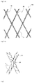
- Figs. 1 and 2 are each an explanatory diagram illustrating a configuration example of a reinforcing member for a tire according to the present invention, in which a part of each of reinforcing members is taken out to be illustrated in (a); and portions of knots of each of the reinforcing members are illustrated in an enlarged manner in (b).
- reinforcing members for a tire 10A, 10B according to the present invention include a network structure made of a plurality of reinforcing materials 1A, 1B, respectively.
- the reinforcing members for a tire 10A, 10B according to the present invention are characterized in that the network structure is made of a knotted net or a knotless net.
- a shearing force between belt layers as in usual belt intersecting layers is not generated so that durability and the like are improved.
- the reinforcing members for a tire 10A, 10B include the network structure made of a knotted net or a knotless net, and reinforcing materials 1A, 1B are bonded to each other not by being fixed by fusion or the like but by being bound to each other respectively at knots 2A, 2B corresponding to respective portions at which the reinforcing materials 1A, 1B intersect each other.
- bend distortions of the reinforcing materials 1A, 1B at respective portions other than the knots 2A, 2B allow a movement of changes in an angle between belt cords due to rolling of a tire to be absorbed, and stress fails to concentrate on the reinforcing materials 1A, 1B at the knots 2A, 2B, respectively. Consequently, in comparison with the conventional structure, a fatigue strength of the reinforcing materials 1A, 1B can be maintained so that durability is improved, thereby enabling suppression of occurrence of fatigue breakage.
- the reinforcing member 10A according to an embodiment of the present invention as illustrated in Fig. 1 includes the network structure made of a knotted net in which the different reinforcing materials 1A are tied to each other, whereby the knot 2A is formed.
- a method of tying the reinforcing materials 1A to each other in this case is not particularly limited and may be any tying method generally known.
- the network structure is formed while the plurality of reinforcing materials 1A are bound to each other by the knots, thereby enabling suppression of occurrence of breakage due to stress concentration as in a case of a network structure in which fusion is performed.
- the reinforcing member 10B according to another embodiment of the present invention as illustrated in Fig. 2 includes the network structure made of a knotless net in which the reinforcing materials 1B in which a plurality of reinforcing cords 3 are twisted together are used, and the reinforcing cords 3 that form the different reinforcing materials 1B are twisted together, whereby the knot 2B is formed.
- two pieces of the reinforcing materials 1B in each of which two pieces of the reinforcing cords 3 are twisted together, are twisted together at the knot 2B in such a manner that one piece of the reinforcing cords 3 that form one of the reinforcing materials 1B penetrates each other between the reinforcing cords 3 that form the other one of the reinforcing materials 1B, thereby being bonded to each other.
- the network structure is formed while the plurality of reinforcing materials 1B are bound to each other by being twisted together, thereby enabling suppression of occurrence of breakage due to stress concentration as in a case of a network structure in which fusion is performed.
- a monofilament made of various types of organic fibers or metal materials that is usually used for a use of reinforcing members for a tire and a twisted cord in which the plurality of monofilaments are appropriately twisted together may be used.
- organic fibers may include nylon, aramid fiber, polyester, and the like.
- metal materials may include steel, and the like.
- the reinforcing materials 1B materials in which the plurality of reinforcing cords 3 are twisted together are used. Also with respect to the reinforcing cords 3 in this case, a monofilament similar to that as described above and a twisted cord in which the plurality of monofilaments are appropriately twisted together may be used. Meanwhile, a number of the reinforcing cords 3 that form the reinforcing materials 1B may be two or more, for example, three to six.
- the reinforcing materials 1A, 1B in a case of the organic fibers, for example, materials having a total fineness of 1100-3300 dtex may be used, and in a case of the metal materials, for example, materials having a diameter of 0.1-6.0 mm may be used. Meanwhile, an implantation number of the reinforcing materials 1A, 1B respectively in the reinforcing members 10A, 10B may be, for example, 8-80 pieces/50 mm in a direction orthogonal to an arrangement direction of the reinforcing materials.
- the reinforcing members according to the present invention may be subjected to adhesive agent treatment in a case in which the reinforcing materials are made of the organic fibers or subjected to plating treatment in a case in which the reinforcing materials are made of the metal materials so as to be provided for manufacturing a tire while covered with a rubber.
- adhesive agent treatment and the plating treatment may be performed in accordance with a conventional method, may be performed after the reinforcing members are manufactured, and may be performed during a step of the reinforcing members or the reinforcing cords.
- Fig. 3 is a widthwise cross-sectional view illustrating a configuration example of a tire according to the present invention.
- the tire as illustrated includes a frame that is a carcass 12 toroidally extending between bead cores 11 correspondingly embedded in a pair of bead portions 21. Meanwhile, a pair of side wall portions 22 are correspondingly arranged on an outer side of the pair of bead portions 21 in a tire radial direction, and a tread portion 23 that forms a ground contact surface is arranged between the pair of side wall portions 22.
- the tire according to the present invention may be any one as long as the tire is reinforced by the above reinforcing members according to the present invention and thereby obtains an effect of improving durability, and is not particularly limited except an arrangement location of the reinforcing members or the like.
- one piece of the reinforcing members 13 in place of a conventional intersecting belt layer is arranged on an outer side of a crown portion of the carcass 12 in the tire radial direction.
- the above reinforcing members in place of a conventional intersecting belt layer is applied in this manner, whereby an reinforcement effect that has been conventionally obtained due to two pieces of intersecting belt layers can be obtained due to one piece of the above reinforcing members, and durability can be also improved.
- the reinforcing members 13 may be disposed at a number of one piece or more, for example, 2-15 pieces. Moreover, in this case, as illustrated, a belt reinforcing layer 14 made of a rubberized layer having reinforcing cords in which a cord direction substantially corresponds to a tire circumferential direction may be further disposed on an inner side of the reinforcing members 13 in the tire radial direction.
- the reinforcing members according to the present invention includes the network structure and the reinforcing materials are not fixed each other at knots so that an angle formed between the reinforcing materials can be flexibly determined, in other words, two reinforcement directions in a tire can be optionally selected.
- An arrangement direction of the reinforcing materials while the reinforcing members according to the present invention are arranged on a tire is not particularly limited and may fall, for example, in a range of 5-65° relative to the tire circumferential direction.
- the reinforcing members according to the present invention are not limited to the embodiments as illustrated, and may be arranged as an additional reinforcing layer on the side wall portions 22 and/or the bead portions 21. Durability of the members themselves is excellent also in this case, whereby a reinforcement effect can be obtained due to arrangement of the members without impairing tire durability.
- the present invention may be applied to, in addition to a tire for a passenger vehicle as illustrated, any type of tires, such as a heavy duty tire that is applied to a heavy duty vehicle, such as a truck and a bus.
- a belt structure as indicated in the below table was applied on the outer side of the crown portion of the carcass in the tire radial direction so as to manufacture a tire for a passenger vehicle in each Example.
- the obtained sample tire in each Example was filled with a standard internal pressure, loaded with 130% of a standard load, and made to travel at a room temperature of 38°C and a speed of 65 km/h, and a travel distance until occurrence of a trouble caused by the intersection portions (knots) of the network structure was measured.
- Example 1 a tire in which as a belt structure, one layer of a thin plate metal net (in which a cylindrical stainless plate having a thickness of 0.14 mm, a width of 200 mm, and a circumference length of 1040 mm was provided with 1320 pieces of elliptical opening portions having a long diameter of 15 mm and a short diameter of 4 mm) in place of one layer of the reinforcing members including the network structure was applied was employed as a conventional example, while, in Examples 2 and 3, a tire in which as a belt structure, three layers of network structures in which knots were formed by fusion (similar to each Example in terms of material of reinforcing members, cord diameter or fineness, implantation number, and cord angle) in place of three layers of the reinforcing members including the network structure were applied was employed as a conventional example, and a ratio (Example/conventional example) of a travel distance of the tire in each Example relative to a travel distance of the tire in each conventional example was determined.
- a ratio Example/
- a belt structure as indicated in the below table was applied on the outer side of the crown portion of the carcass in the tire radial direction so as to manufacture a tire for a heavy duty vehicle in each Example.
- the obtained sample tire in each Example was filled with a standard internal pressure, loaded with 150% of the standard load, and made to travel at a room temperature of 38°C and a speed of 72 km/h, and a travel distance until occurrence of a trouble caused by the intersection portions (knots) of the network structure was measured.
- a tire in which as a belt structure, three layers of thin plate metal nets (in which a cylindrical stainless plate having a thickness of 0.5 mm, a width of 220 mm, and a circumference length of 3095 mm was provided with 3930 pieces of elliptical opening portions having a long diameter of 18 mm and a short diameter of 6 mm) in place of three layer of the reinforcing members including the network structure were applied was employed as a conventional example, and a ratio (Example/conventional example) of a travel distance of the tire in the Example relative to a travel distance of the tire in the conventional example was determined.
- a belt structure having three layers of the reinforcing members of the network structure (see Fig. 1 ) made of aramid cords (fineness: 1670 dtex/ 2 pieces).
- a belt structure having three layers of the reinforcing members of the network structure (see Fig. 1 ) made of polyester cords (fineness: 1670 dtex/ 2 pieces) and one layer of a reinforcing layer made of reinforcing cords (material: steel, diameter: 0.6 mm) having a cord angle of 90° relative to a tire width direction that were arranged on an inner side in a tire radial direction thereof.
- a belt structure having three layers of the reinforcing members of the network structure made of steel cords (structure in which two monofilaments having a cord diameter of 0.6 mm were twisted together) and two layers of reinforcing layers made of reinforcing cords (material: steel, diameter: 1.2 mm) having a cord angle of 90° relative to a tire width direction that were arranged on an inner side in a tire radial direction thereof.
Abstract
Description
- The present invention relates to a reinforcing member for a tire (hereinafter also simply referred to as "reinforcing member") and a tire using the same, and more particularly to a reinforcing member for a tire that is related to an improvement of a member structure and a tire using the same.
- With respect to reinforcing members for a tire, various studies have been conventionally conducted. For example, as reinforcing structures for a tire for a passenger vehicle, a structure in which two or more belt intersecting layers in which cord directions of reinforcing cords intersect each other are arranged on an outer side of a crown portion of a carcass that serves as a frame member in a tire radial direction is commonly known.
- Moreover, for example,
Patent Document 1 discloses a radial tire for a motorcycle in which a belt is configured to include a network body including a first belt cord array body and a second belt cord array body that intersect each other, and each of intersection portions of belt cords is fused in order to maintain conventional properties while preventing occurrence of damages starting from a belt end and improving high speed durability and processability. - Patent Document 1:
Japanese Unexamined Patent Application Publication No. 2012-192789 - However, as in
Patent Document 1, in a structure in which the intersection portions of the belt cords are fixed by fusion, when an angle between the belt cords intersecting each other changes during rolling of a tire, stress concentration occurs at the intersection portions, and the belt cords may be broken due to repeated fatigue. Accordingly, achieving a tire in which problems of such breakage of belt cords are solved and tire durability is further improved has been desired. - Thus it is an object of the present invention to provide a reinforcing member for a tire that can further improve tire durability by solving the above problems and enhancing durability of members themselves, and a tire in which durability is further improved by using the same.
- As a result of intensive studies, the present inventor has found out that a reinforcing member for a tire that includes a network structure in which knots are formed without chemical bonding, such as fusion, allows the above problems to be solved, thereby completing the present invention.
- Specifically, the reinforcing member for a tire according to the present invention is a reinforcing member for a tire that includes a network structure made of a plurality of reinforcing materials, in which the network structure is made of a knotted net or a knotless net.
- In the reinforcing member according to the present invention, it is preferable that the network structure is made of the knotted net in which the different reinforcing materials are tied to each other, whereby a knot is formed. Moreover, in the reinforcing member according to the present invention, it is also preferable that the reinforcing materials are formed by twisting a plurality of reinforcing cords together, and the network structure is made of the knotless net in which the reinforcing cords that form the different reinforcing materials are twisted together, whereby a knot is formed.
- Moreover, the tire according to the present invention is reinforced by the above reinforcing member for a tire according to the present invention.
- According to the present invention, durability of members themselves can be enhanced by employing the above configuration, and a tire in which tire durability is further improved can be achieved by using the same.
-
-
Fig. 1 is an explanatory diagram illustrating a configuration example of a reinforcing member for a tire according to the present invention. -
Fig. 2 is an explanatory diagram illustrating another configuration example of the reinforcing member for a tire according to the present invention. -
Fig. 3 is a widthwise cross-sectional view illustrating a configuration example of a tire according to the present invention. - Hereinafter, embodiments of the present invention will be described in detail with reference to the drawings.
-
Figs. 1 and2 are each an explanatory diagram illustrating a configuration example of a reinforcing member for a tire according to the present invention, in which a part of each of reinforcing members is taken out to be illustrated in (a); and portions of knots of each of the reinforcing members are illustrated in an enlarged manner in (b). As illustrated, reinforcing members for atire materials - The reinforcing members for a
tire tire materials knots materials materials knots materials knots materials - The reinforcing
member 10A according to an embodiment of the present invention as illustrated inFig. 1 includes the network structure made of a knotted net in which the different reinforcingmaterials 1A are tied to each other, whereby theknot 2A is formed. A method of tying the reinforcingmaterials 1A to each other in this case is not particularly limited and may be any tying method generally known. In this manner, the network structure is formed while the plurality of reinforcingmaterials 1A are bound to each other by the knots, thereby enabling suppression of occurrence of breakage due to stress concentration as in a case of a network structure in which fusion is performed. - The reinforcing
member 10B according to another embodiment of the present invention as illustrated inFig. 2 includes the network structure made of a knotless net in which the reinforcingmaterials 1B in which a plurality of reinforcingcords 3 are twisted together are used, and the reinforcingcords 3 that form the different reinforcingmaterials 1B are twisted together, whereby theknot 2B is formed. In the embodiment as illustrated, two pieces of thereinforcing materials 1B, in each of which two pieces of the reinforcingcords 3 are twisted together, are twisted together at theknot 2B in such a manner that one piece of the reinforcingcords 3 that form one of the reinforcingmaterials 1B penetrates each other between the reinforcingcords 3 that form the other one of the reinforcingmaterials 1B, thereby being bonded to each other. Also in this case, the network structure is formed while the plurality of reinforcingmaterials 1B are bound to each other by being twisted together, thereby enabling suppression of occurrence of breakage due to stress concentration as in a case of a network structure in which fusion is performed. - As the reinforcing
materials members - In particular, as the reinforcing
materials 1B, materials in which the plurality of reinforcingcords 3 are twisted together are used. Also with respect to the reinforcingcords 3 in this case, a monofilament similar to that as described above and a twisted cord in which the plurality of monofilaments are appropriately twisted together may be used. Meanwhile, a number of the reinforcingcords 3 that form the reinforcingmaterials 1B may be two or more, for example, three to six. - As the reinforcing
materials materials members - The reinforcing members according to the present invention may be subjected to adhesive agent treatment in a case in which the reinforcing materials are made of the organic fibers or subjected to plating treatment in a case in which the reinforcing materials are made of the metal materials so as to be provided for manufacturing a tire while covered with a rubber. These adhesive agent treatment and the plating treatment may be performed in accordance with a conventional method, may be performed after the reinforcing members are manufactured, and may be performed during a step of the reinforcing members or the reinforcing cords.
-
Fig. 3 is a widthwise cross-sectional view illustrating a configuration example of a tire according to the present invention. The tire as illustrated includes a frame that is acarcass 12 toroidally extending betweenbead cores 11 correspondingly embedded in a pair ofbead portions 21. Meanwhile, a pair ofside wall portions 22 are correspondingly arranged on an outer side of the pair ofbead portions 21 in a tire radial direction, and atread portion 23 that forms a ground contact surface is arranged between the pair ofside wall portions 22. - The tire according to the present invention may be any one as long as the tire is reinforced by the above reinforcing members according to the present invention and thereby obtains an effect of improving durability, and is not particularly limited except an arrangement location of the reinforcing members or the like. For example, in an embodiment as illustrated, one piece of the reinforcing
members 13 in place of a conventional intersecting belt layer is arranged on an outer side of a crown portion of thecarcass 12 in the tire radial direction. According to the present invention, the above reinforcing members in place of a conventional intersecting belt layer is applied in this manner, whereby an reinforcement effect that has been conventionally obtained due to two pieces of intersecting belt layers can be obtained due to one piece of the above reinforcing members, and durability can be also improved. - The reinforcing
members 13 may be disposed at a number of one piece or more, for example, 2-15 pieces. Moreover, in this case, as illustrated, abelt reinforcing layer 14 made of a rubberized layer having reinforcing cords in which a cord direction substantially corresponds to a tire circumferential direction may be further disposed on an inner side of the reinforcingmembers 13 in the tire radial direction. - The reinforcing members according to the present invention includes the network structure and the reinforcing materials are not fixed each other at knots so that an angle formed between the reinforcing materials can be flexibly determined, in other words, two reinforcement directions in a tire can be optionally selected. An arrangement direction of the reinforcing materials while the reinforcing members according to the present invention are arranged on a tire is not particularly limited and may fall, for example, in a range of 5-65° relative to the tire circumferential direction.
- The reinforcing members according to the present invention are not limited to the embodiments as illustrated, and may be arranged as an additional reinforcing layer on the
side wall portions 22 and/or thebead portions 21. Durability of the members themselves is excellent also in this case, whereby a reinforcement effect can be obtained due to arrangement of the members without impairing tire durability. - The present invention may be applied to, in addition to a tire for a passenger vehicle as illustrated, any type of tires, such as a heavy duty tire that is applied to a heavy duty vehicle, such as a truck and a bus.
- Hereinafter, the present invention will be described further in detail with reference to Examples.
- A belt structure as indicated in the below table was applied on the outer side of the crown portion of the carcass in the tire radial direction so as to manufacture a tire for a passenger vehicle in each Example. The obtained sample tire in each Example was filled with a standard internal pressure, loaded with 130% of a standard load, and made to travel at a room temperature of 38°C and a speed of 65 km/h, and a travel distance until occurrence of a trouble caused by the intersection portions (knots) of the network structure was measured.
- In Example 1, a tire in which as a belt structure, one layer of a thin plate metal net (in which a cylindrical stainless plate having a thickness of 0.14 mm, a width of 200 mm, and a circumference length of 1040 mm was provided with 1320 pieces of elliptical opening portions having a long diameter of 15 mm and a short diameter of 4 mm) in place of one layer of the reinforcing members including the network structure was applied was employed as a conventional example, while, in Examples 2 and 3, a tire in which as a belt structure, three layers of network structures in which knots were formed by fusion (similar to each Example in terms of material of reinforcing members, cord diameter or fineness, implantation number, and cord angle) in place of three layers of the reinforcing members including the network structure were applied was employed as a conventional example, and a ratio (Example/conventional example) of a travel distance of the tire in each Example relative to a travel distance of the tire in each conventional example was determined.
- A belt structure as indicated in the below table was applied on the outer side of the crown portion of the carcass in the tire radial direction so as to manufacture a tire for a heavy duty vehicle in each Example. The obtained sample tire in each Example was filled with a standard internal pressure, loaded with 150% of the standard load, and made to travel at a room temperature of 38°C and a speed of 72 km/h, and a travel distance until occurrence of a trouble caused by the intersection portions (knots) of the network structure was measured. A tire in which as a belt structure, three layers of thin plate metal nets (in which a cylindrical stainless plate having a thickness of 0.5 mm, a width of 220 mm, and a circumference length of 3095 mm was provided with 3930 pieces of elliptical opening portions having a long diameter of 18 mm and a short diameter of 6 mm) in place of three layer of the reinforcing members including the network structure were applied was employed as a conventional example, and a ratio (Example/conventional example) of a travel distance of the tire in the Example relative to a travel distance of the tire in the conventional example was determined.
- Results of these are collectively indicated in the below table. It is indicated that the greater the ratio of the travel distance is, the more durability is improved with respect to the conventional example.
[Table 1] Tire size Belt structure Material of reinforcing member Type of network structure Implantation number (pieces/50 mm) Angle relative to tire circumferential direction (°) Travel distance (ratio) Example 1 PSR 255/35R20 One layer of network sructure*1 Steel Knotless 32 20 1.3 Example 2 PSR 155/65R13 Three layers of network structure*2 Aramid Knotted 36 45 1.2 Example 3 PSR 155/65R13 Three layers of network structure and one reinforcing layer of 90°*3 Polyester Knotted 50 45 1.25 Example 4 TBR 11R22.5 Three layers of network structure and two reinforcing layers of 90°*4 Steel Knotless 21 45 1.3 *1) A belt structure having one layer of the reinforcing members of the network structure (see Fig. 2 ) made of steel cords (structure in which two monofilaments having a cord diameter of 0.35 mm were twisted together).
*2) A belt structure having three layers of the reinforcing members of the network structure (seeFig. 1 ) made of aramid cords (fineness: 1670 dtex/ 2 pieces).
*3) A belt structure having three layers of the reinforcing members of the network structure (seeFig. 1 ) made of polyester cords (fineness: 1670 dtex/ 2 pieces) and one layer of a reinforcing layer made of reinforcing cords (material: steel, diameter: 0.6 mm) having a cord angle of 90° relative to a tire width direction that were arranged on an inner side in a tire radial direction thereof.
*4) A belt structure having three layers of the reinforcing members of the network structure (seeFig. 2 ) made of steel cords (structure in which two monofilaments having a cord diameter of 0.6 mm were twisted together) and two layers of reinforcing layers made of reinforcing cords (material: steel, diameter: 1.2 mm) having a cord angle of 90° relative to a tire width direction that were arranged on an inner side in a tire radial direction thereof. - As known from the results in the above table, in the tire in each Example in which the reinforcing members including the network structure made of a knotted net or a knotless net, it is clear that durability is improved in comparison with the conventional examples.
-
- 1A, 1B
- Reinforcing material
- 2A, 2B
- Knot
- 3
- Reinforcing cord
- 10A, 10B
- Reinforcing member
- 11
- Bead core
- 12
- Carcass
- 13
- Reinforcing member
- 14
- Belt reinforcing layer
- 21
- Bead portion
- 22
- Side wall portion
- 23
- Tread portion
Claims (4)
- A reinforcing member for a tire, comprising a network structure made of a plurality of reinforcing materials,
wherein the network structure is made of a knotted net or a knotless net. - The reinforcing member for a tire according to claim 1,
wherein the network structure is made of the knotted net in which the different reinforcing materials are tied to each other, whereby a knot is formed. - The reinforcing member for a tire according to claim 1,
wherein the reinforcing materials are formed by twisting a plurality of reinforcing cords together, and the network structure is made of the knotless net in which the reinforcing cords that form the different reinforcing materials are twisted together, whereby a knot is formed. - A tire reinforced by the reinforcing member for a tire according to claim 1.
Applications Claiming Priority (2)
| Application Number | Priority Date | Filing Date | Title |
|---|---|---|---|
| JP2013148424A JP2015020492A (en) | 2013-07-17 | 2013-07-17 | Tire reinforcement member and tire using the same |
| PCT/JP2014/064500 WO2015008547A1 (en) | 2013-07-17 | 2014-05-30 | Reinforcing member for tire, and tire using same |
Publications (2)
| Publication Number | Publication Date |
|---|---|
| EP3023265A1 true EP3023265A1 (en) | 2016-05-25 |
| EP3023265A4 EP3023265A4 (en) | 2016-07-27 |
Family
ID=52346021
Family Applications (1)
| Application Number | Title | Priority Date | Filing Date |
|---|---|---|---|
| EP14826503.6A Withdrawn EP3023265A4 (en) | 2013-07-17 | 2014-05-30 | Reinforcing member for tire, and tire using same |
Country Status (5)
| Country | Link |
|---|---|
| US (1) | US20160167436A1 (en) |
| EP (1) | EP3023265A4 (en) |
| JP (1) | JP2015020492A (en) |
| CN (1) | CN105431305A (en) |
| WO (1) | WO2015008547A1 (en) |
Cited By (1)
| Publication number | Priority date | Publication date | Assignee | Title |
|---|---|---|---|---|
| EP3854920A4 (en) * | 2018-12-19 | 2021-12-08 | Kolon Industries, Inc. | Protective net for sports , and golf protective net, soccer protective net, baseball protective net, tennis protective net, and volleyball protective net using same |
Families Citing this family (4)
| Publication number | Priority date | Publication date | Assignee | Title |
|---|---|---|---|---|
| JP6587825B2 (en) * | 2015-05-13 | 2019-10-09 | 株式会社ブリヂストン | Pneumatic tires for passenger cars |
| WO2017022819A1 (en) | 2015-08-06 | 2017-02-09 | 横浜ゴム株式会社 | Pneumatic tire |
| CN106938593B (en) * | 2017-04-24 | 2019-04-02 | 江苏通用科技股份有限公司 | High centrifugal force resistant tire crown structure |
| IT201900024442A1 (en) * | 2019-12-18 | 2021-06-18 | Bridgestone Europe Nv Sa | TIRE WITH BELT PACK REINFORCEMENT ELEMENT |
Family Cites Families (9)
| Publication number | Priority date | Publication date | Assignee | Title |
|---|---|---|---|---|
| US493488A (en) * | 1893-03-14 | Pneumatic tire | ||
| US3255614A (en) * | 1966-06-14 | Process for the production of reinforcing inlays for rubber articles | ||
| US694223A (en) * | 1901-05-14 | 1902-02-25 | William Frederick Williams | Elastic tire. |
| GB1174292A (en) * | 1966-03-14 | 1969-12-17 | Brunswick Corp | Composite Materials |
| JPS476177U (en) * | 1971-02-12 | 1972-09-20 | ||
| CN2451372Y (en) * | 2000-11-07 | 2001-10-03 | 才海生 | Tyre protection bushing |
| US7252129B2 (en) * | 2005-02-22 | 2007-08-07 | Milliken & Company | Tire with cap ply layer |
| JP4866892B2 (en) * | 2008-10-29 | 2012-02-01 | 帝人ファイバー株式会社 | Shock absorbing net and protective body using the same |
| JP2012192789A (en) * | 2011-03-15 | 2012-10-11 | Sumitomo Rubber Ind Ltd | Radial tire for motorcycle, and method for manufacturing the same |
-
2013
- 2013-07-17 JP JP2013148424A patent/JP2015020492A/en active Pending
-
2014
- 2014-05-30 CN CN201480040567.XA patent/CN105431305A/en active Pending
- 2014-05-30 US US14/905,543 patent/US20160167436A1/en not_active Abandoned
- 2014-05-30 EP EP14826503.6A patent/EP3023265A4/en not_active Withdrawn
- 2014-05-30 WO PCT/JP2014/064500 patent/WO2015008547A1/en active Application Filing
Cited By (1)
| Publication number | Priority date | Publication date | Assignee | Title |
|---|---|---|---|---|
| EP3854920A4 (en) * | 2018-12-19 | 2021-12-08 | Kolon Industries, Inc. | Protective net for sports , and golf protective net, soccer protective net, baseball protective net, tennis protective net, and volleyball protective net using same |
Also Published As
| Publication number | Publication date |
|---|---|
| WO2015008547A1 (en) | 2015-01-22 |
| EP3023265A4 (en) | 2016-07-27 |
| US20160167436A1 (en) | 2016-06-16 |
| JP2015020492A (en) | 2015-02-02 |
| CN105431305A (en) | 2016-03-23 |
Similar Documents
| Publication | Publication Date | Title |
|---|---|---|
| EP2065511B1 (en) | Rubber reinforcing steel cord and pneumatic radial tire | |
| EP3196354A1 (en) | Steel cord for reinforcing rubber article | |
| EP3023265A1 (en) | Reinforcing member for tire, and tire using same | |
| US10895037B2 (en) | Steel cord for reinforcing rubber article | |
| US10906353B2 (en) | Steel cord for reinforcing rubber article | |
| EP2639082B1 (en) | Pneumatic tire | |
| EP3196355B1 (en) | Steel cord for reinforcing rubber article | |
| CN106715790A (en) | Steel cord for reinforcing rubber article, and pneumatic tire using same | |
| EP3381714B1 (en) | Motorcycle tire | |
| EP3196353B1 (en) | Steel cord for reinforcing rubber article | |
| JP5083943B2 (en) | Steel cord for reinforcing rubber articles and pneumatic tire using the same | |
| EP3603995B1 (en) | Pneumatic tire | |
| EP3132948B1 (en) | Tire | |
| EP3279010B1 (en) | Cord-rubber composite and pneumatic tire | |
| EP3854608B1 (en) | Composite cord and tire using same | |
| EP2829420B1 (en) | Pneumatic tyres for a vehicle | |
| CN114729504B (en) | Double layer multi-ply cord with a coated inner layer and improved permeability | |
| JP5619360B2 (en) | Steel cords for reinforcing rubber articles and pneumatic tires | |
| EP3335906A1 (en) | Pneumatic tire | |
| JP2005002518A (en) | Steel cord for rubber reinforcement and pneumatic radial tire | |
| JPH08127986A (en) | Steel cord for reinforcing rubber and radial tire using the same | |
| CN116490653A (en) | Double layer multi-ply cord with a coated inner layer and improved permeability | |
| JP2005212583A (en) | Pneumatic bias tire for heavy load | |
| JP2006249636A (en) | Steel cord | |
| JPH09188981A (en) | Steel cord for reinforcing rubber article and pneumatic tire |
Legal Events
| Date | Code | Title | Description |
|---|---|---|---|
| PUAI | Public reference made under article 153(3) epc to a published international application that has entered the european phase |
Free format text: ORIGINAL CODE: 0009012 |
|
| 17P | Request for examination filed |
Effective date: 20160212 |
|
| AK | Designated contracting states |
Kind code of ref document: A1 Designated state(s): AL AT BE BG CH CY CZ DE DK EE ES FI FR GB GR HR HU IE IS IT LI LT LU LV MC MK MT NL NO PL PT RO RS SE SI SK SM TR |
|
| AX | Request for extension of the european patent |
Extension state: BA ME |
|
| A4 | Supplementary search report drawn up and despatched |
Effective date: 20160629 |
|
| RIC1 | Information provided on ipc code assigned before grant |
Ipc: B60C 9/00 20060101ALI20160623BHEP Ipc: B60C 9/11 20060101AFI20160623BHEP Ipc: B60C 9/18 20060101ALI20160623BHEP Ipc: D04G 1/00 20060101ALI20160623BHEP Ipc: D04C 1/06 20060101ALI20160623BHEP Ipc: D04C 1/08 20060101ALI20160623BHEP Ipc: D04C 1/12 20060101ALI20160623BHEP |
|
| DAX | Request for extension of the european patent (deleted) | ||
| 17Q | First examination report despatched |
Effective date: 20180126 |
|
| GRAP | Despatch of communication of intention to grant a patent |
Free format text: ORIGINAL CODE: EPIDOSNIGR1 |
|
| INTG | Intention to grant announced |
Effective date: 20181205 |
|
| STAA | Information on the status of an ep patent application or granted ep patent |
Free format text: STATUS: THE APPLICATION IS DEEMED TO BE WITHDRAWN |
|
| 18D | Application deemed to be withdrawn |
Effective date: 20190416 |