EP2829420B1 - Pneumatic tyres for a vehicle - Google Patents
Pneumatic tyres for a vehicle Download PDFInfo
- Publication number
- EP2829420B1 EP2829420B1 EP14168048.8A EP14168048A EP2829420B1 EP 2829420 B1 EP2829420 B1 EP 2829420B1 EP 14168048 A EP14168048 A EP 14168048A EP 2829420 B1 EP2829420 B1 EP 2829420B1
- Authority
- EP
- European Patent Office
- Prior art keywords
- bandage
- belt
- pneumatic vehicle
- reinforcing elements
- side regions
- Prior art date
- Legal status (The legal status is an assumption and is not a legal conclusion. Google has not performed a legal analysis and makes no representation as to the accuracy of the status listed.)
- Active
Links
- 230000003014 reinforcing effect Effects 0.000 claims description 16
- 238000004519 manufacturing process Methods 0.000 claims description 6
- 230000002787 reinforcement Effects 0.000 description 29
- 229920000139 polyethylene terephthalate Polymers 0.000 description 21
- 239000005020 polyethylene terephthalate Substances 0.000 description 21
- 239000004760 aramid Substances 0.000 description 11
- 229920003235 aromatic polyamide Polymers 0.000 description 9
- 239000000463 material Substances 0.000 description 7
- 238000005520 cutting process Methods 0.000 description 6
- 239000011324 bead Substances 0.000 description 4
- 239000000203 mixture Substances 0.000 description 4
- 239000011112 polyethylene naphthalate Substances 0.000 description 4
- 239000000835 fiber Substances 0.000 description 3
- 238000000034 method Methods 0.000 description 3
- 229920003207 poly(ethylene-2,6-naphthalate) Polymers 0.000 description 3
- 239000012744 reinforcing agent Substances 0.000 description 3
- 239000004952 Polyamide Substances 0.000 description 2
- 239000000853 adhesive Substances 0.000 description 2
- 230000001070 adhesive effect Effects 0.000 description 2
- 229920006231 aramid fiber Polymers 0.000 description 2
- 239000000969 carrier Substances 0.000 description 2
- 238000005470 impregnation Methods 0.000 description 2
- 229920001778 nylon Polymers 0.000 description 2
- 229920002647 polyamide Polymers 0.000 description 2
- 230000008092 positive effect Effects 0.000 description 2
- 239000004677 Nylon Substances 0.000 description 1
- -1 Polyethylene Terephthalate Polymers 0.000 description 1
- 230000002411 adverse Effects 0.000 description 1
- 238000003490 calendering Methods 0.000 description 1
- 239000002131 composite material Substances 0.000 description 1
- 150000001875 compounds Chemical class 0.000 description 1
- 238000010276 construction Methods 0.000 description 1
- 230000000994 depressogenic effect Effects 0.000 description 1
- 230000002349 favourable effect Effects 0.000 description 1
- 238000005457 optimization Methods 0.000 description 1
- 230000000704 physical effect Effects 0.000 description 1
- 238000005096 rolling process Methods 0.000 description 1
- 238000004073 vulcanization Methods 0.000 description 1
Images
Classifications
-
- B—PERFORMING OPERATIONS; TRANSPORTING
- B60—VEHICLES IN GENERAL
- B60C—VEHICLE TYRES; TYRE INFLATION; TYRE CHANGING; CONNECTING VALVES TO INFLATABLE ELASTIC BODIES IN GENERAL; DEVICES OR ARRANGEMENTS RELATED TO TYRES
- B60C9/00—Reinforcements or ply arrangement of pneumatic tyres
- B60C9/18—Structure or arrangement of belts or breakers, crown-reinforcing or cushioning layers
- B60C9/20—Structure or arrangement of belts or breakers, crown-reinforcing or cushioning layers built-up from rubberised plies each having all cords arranged substantially parallel
- B60C9/22—Structure or arrangement of belts or breakers, crown-reinforcing or cushioning layers built-up from rubberised plies each having all cords arranged substantially parallel the plies being arranged with all cords disposed along the circumference of the tyre
- B60C2009/2223—Structure or arrangement of belts or breakers, crown-reinforcing or cushioning layers built-up from rubberised plies each having all cords arranged substantially parallel the plies being arranged with all cords disposed along the circumference of the tyre with an interrupted zero degree ply, e.g. using two or more portions for the same ply
-
- B—PERFORMING OPERATIONS; TRANSPORTING
- B60—VEHICLES IN GENERAL
- B60C—VEHICLE TYRES; TYRE INFLATION; TYRE CHANGING; CONNECTING VALVES TO INFLATABLE ELASTIC BODIES IN GENERAL; DEVICES OR ARRANGEMENTS RELATED TO TYRES
- B60C9/00—Reinforcements or ply arrangement of pneumatic tyres
- B60C9/18—Structure or arrangement of belts or breakers, crown-reinforcing or cushioning layers
- B60C9/20—Structure or arrangement of belts or breakers, crown-reinforcing or cushioning layers built-up from rubberised plies each having all cords arranged substantially parallel
- B60C9/22—Structure or arrangement of belts or breakers, crown-reinforcing or cushioning layers built-up from rubberised plies each having all cords arranged substantially parallel the plies being arranged with all cords disposed along the circumference of the tyre
- B60C2009/2252—Physical properties or dimension of the zero degree ply cords
- B60C2009/2261—Modulus of the cords
-
- B—PERFORMING OPERATIONS; TRANSPORTING
- B60—VEHICLES IN GENERAL
- B60C—VEHICLE TYRES; TYRE INFLATION; TYRE CHANGING; CONNECTING VALVES TO INFLATABLE ELASTIC BODIES IN GENERAL; DEVICES OR ARRANGEMENTS RELATED TO TYRES
- B60C9/00—Reinforcements or ply arrangement of pneumatic tyres
- B60C9/18—Structure or arrangement of belts or breakers, crown-reinforcing or cushioning layers
- B60C9/20—Structure or arrangement of belts or breakers, crown-reinforcing or cushioning layers built-up from rubberised plies each having all cords arranged substantially parallel
- B60C9/22—Structure or arrangement of belts or breakers, crown-reinforcing or cushioning layers built-up from rubberised plies each having all cords arranged substantially parallel the plies being arranged with all cords disposed along the circumference of the tyre
- B60C2009/2252—Physical properties or dimension of the zero degree ply cords
- B60C2009/2295—Physical properties or dimension of the zero degree ply cords with different cords in the same layer
Definitions
- the invention relates to a pneumatic vehicle tire with a carcass, a tread, arranged between the tread and carcass belt and arranged on the radially outer side of the belt, at least one bandage layer having belt bandage with circumferentially applied strength members, wherein the belt bandage in its axial extent in two Side regions and a central region containing a respective bandage layer part is divided, wherein the strength of the Stromal Bandagenlagenteils in the middle region of polyamide 6.6 (PA6.6) are formed and wherein the strength of the carrier support web parts parts in the two side regions have a higher modulus than PA6.6.
- PA6.6 polyamide 6.6
- Reinforcements for reinforcing pneumatic vehicle tires are well known.
- a belt bandage which is formed in one or more layers, covering the belt edges and parallel and extending substantially in the circumferential direction of the strength member in the form of embedded in the rubber reinforcement.
- the belt bandage is applied in the manufacture of tires in the form of layers, strips or individual reinforcements with embedded in an unvulcanized rubber compound reinforcing agents that are wound or wound on the belt.
- the reinforcing members are previously embedded either in rubber by a longitudinally one set of substantially parallel filiform reinforcing members, which are usually pretreated with a thermal impregnation and / or for better adhesion to the embedding rubber in a known manner Calender or an extruder to coat with the rubber mixture passes. Or else strength carriers are applied, which are tacky impregnated and can be processed without a calendered adhesive mixture.
- This belt bandage serves, in particular in high-speed deployment, to limit an elevation of the tire due to the centrifugal forces occurring during driving.
- the reinforcements of the belt bandage should hold down the belt layers, in particular the belt edges for high-speed stability and durability. For this purpose, larger forces must be bound in the shoulder regions of the pneumatic vehicle tire than in the middle region.
- Tire development tends to improve the high speed durability and durability of the pneumatic vehicle tires.
- the pneumatic vehicle tire has a belt bandage which has in its center region a bandage layer part whose cords have a lower modulus of elasticity than the cords of bandage ply parts in the side regions.
- a belt bandage When driving, especially in high-speed use, the use of high-modulus material in the side regions allows a good binding of the forces occurring there, whereas the pneumatic vehicle tire developed by the lower-modulus PA6.6 in the central region a round contour and thus has positive high-speed properties.
- Such a belt bandage thus has a positive effect on the high-speed stability and durability of the pneumatic vehicle tire.
- a pneumatic vehicle tire with a belt bandage whose side regions comprise cords comprising polyethylene naphthalate (PEN) fibers, aramid fibers or a composite of aramid fibers and nylon fibers which have a higher modulus of elasticity than the cords PA6.6 used in the middle region.
- PEN polyethylene naphthalate
- aramid fibers or a composite of aramid fibers and nylon fibers which have a higher modulus of elasticity than the cords PA6.6 used in the middle region.
- a pneumatic vehicle tire having a belt bandage covering the belt is known from three axially adjacent belt bandage ply parts, the two bandage ply portions of the side regions being PET, preferably PEN, and the midband region being nylon.
- the bandage ply portion of the center region should be made of fewer plies than either of the two bandage ply portions of the side regions.
- the object is achieved in that the strength members of the bandage ply parts are formed in the two side regions of HMLS PET.
- a pneumatic vehicle tire whose belt bandage has in its central region a bandage layer part whose reinforcements are formed of PA6.6, and in each side region has a bandage layer part whose reinforcements are made of HMLS PET.
- the HMLS PET is a so-called High Modulus Low Shrinkage Polyethylene Terephthalate (HMLS PET).
- HMLS PET High Modulus Low Shrinkage Polyethylene Terephthalate
- Such a reinforcement should have a shrinkage at 180 ° C according to ASTM D 855 2% ⁇ 1.0% for use in tires.
- the strength element should have a tensile strength of more than 0.35 cN / dtex at 2% elongation at 160 ° C., a tensile strength of more than 0.70 cN / dtex at 4% elongation and a tensile strength of more than 1.20 cN at 6% elongation / dtex.
- the cutting or cutting of reinforcements made of HMLS PET is simpler and than the cutting or cutting to length of reinforcements containing aramid. As a result, complex measures and additional processes are avoided and the pneumatic vehicle tire can be manufactured in a simple manner.
- a pneumatic vehicle tire whose belt bandage comprises HMLS PET reinforcements is characterized by very good durability.
- HMLS PET has favorable shrink properties, high fatigue resistance and very good adhesion to the elastomeric blend.
- Reinforcements made of HMLS PET have a higher modulus of elasticity than polyamide 6.6 (PA6.6) used for the reinforcements of the middle part of the bandage.
- PA6.6 polyamide 6.6
- When driving, especially in high-speed deployment thus takes place in the side areas a good bond the forces occurring there, whereas the pneumatic vehicle tire developed by the lower-modulus PA6.6 in the central region a round contour and thus has positive high-speed properties.
- Such a belt bandage thus has a positive effect on the high-speed stability and durability of the pneumatic vehicle tire.
- reinforcements made of HMLS PET are generally more cost-effective and have better market availability than reinforcements made of PEN or reinforcements containing aramid.
- a high-speed and durable vehicle tire is provided with a belt bandage, which is cheaper and can be manufactured in a simple manner.
- the reinforcing agent In order to ensure a reliable adhesion of a reinforcing agent to the rubber, it is expedient to provide the reinforcing agent with an adhesive impregnation, e.g. with an RFL dip in 1-bath or 2-bath process.
- the belt bandage covers at least the radially outer belt edges.
- the Bandagenlagenmaschine the belt bandage are applied in the manufacture of the pneumatic vehicle tire sequentially or simultaneously, preferably wound or wound.
- Bandage ply parts of a side region and of the middle region of a bandage ply are applied in the axial direction in a contacting, overlapping or spaced manner, in particular with an overlap or distance of approximately one rubberizing thickness.
- a resulting gap between the bandage layer parts in the axial direction is filled in the further manufacturing process of the pneumatic vehicle tire by the rubber surrounding the gap components. In the finished pneumatic vehicle tire, this rubber is attributed below to the axially inner bandage layer part.
- Two adjacent bandage ply members may have the same strength member which is applied continuously over the entire axial width of the two Bandagenlagenmaschine.
- the belt bandage has a bandage layer which has a bandage layer part with reinforcements made of PA6.6 in the center area and a bandage layer part with reinforcements made of HMLS PET in each of the two side areas.
- a pneumatic vehicle tire with a belt bandage containing such a bandage ply has good high speed durability and improved durability.
- the belt bandage has a further bandage layer.
- the further bandage ply can be arranged radially outside or radially inside the bandage ply comprising bandage ply parts according to the invention.
- the reinforcements of the further bandage layer can all be formed from one material, in particular PA6.6.
- the reinforcing elements of the further bandage layer may also differ from bandage ply part to bandage ply part in their material.
- the first and / or the second bandage ply in particular the radially inner bandage ply, has a bandage ply portion both in the center region and in both side regions.
- the strength members of the bandage ply portions of a bandage ply may all be formed of the same material or differ in their material.
- the radially inner bandage layer has in the middle region as well as in the side regions Bandagenlagenmaschine, wherein the strength members are formed of PA6.6 and are applied continuously over the entire axial extent of the bandage layer.
- each of the two side regions has an axial width of 3% to 47%, in particular of 5% to 30%, in particular of 10% to 20%, of the axial width of the belt bandage, measured along the contour of the belt bandage.
- Such a belt bandage ensures that the belt edges are optimally depressed during vulcanization and driving.
- a pneumatic vehicle tire having such a belt bandage thus has optimum durability and high speed stability.
- the reinforcements are yarns and / or cords.
- HMLS PET and / or PA6.6 yarns and / or cords are cost-effective reinforcements and have high market availability.
- a "cord” represents a linear structure consisting of two or more twisted yarns.
- a “yarn” is a linear structure of several fibers.
- the reinforcements are yarns and / or cords, wherein the fineness of the yarns and / or the yarns of the cords is 200 dtex to 2200 dtex. With a fineness of less than 200 dtex, sufficient strength would no longer be present, while a fineness of more than 2200 dtex would entail disadvantages due to unnecessarily much material, e.g. Rolling resistance disadvantages of the pneumatic vehicle tire.
- the yarns preferably have a fineness of 700 dtex to 1800 dtex.
- the cords of HMLS PET comprise one, two or more such yarns and the cords of PA6.6 one, two or more such yarns.
- Cords made of HMLS PET are particularly preferably made from two 1440 dtex yarns twisted together with one another and cords made of PA6.6 from two end-twisted yarns having a fineness of 1400 dtex or 940 dtex.
- the strength members of the bandage layer part are applied in the middle region, and the strength carriers of the bandage layer parts in the side regions are applied with the same pretension.
- the strength members are in particular wound or wound.
- the tensile stress of the reinforcement is adjusted by controlling the bias voltage targeted.
- the strength carrier of the Bandagenlagenteils are applied in the central region with a different bias than the strength carrier of the Bandagenlagenmaschine in the side regions.
- the strength members are in particular wound or wound.
- the tension of the strength members in the different bandage layer parts are thus adjusted by the regulation of the bias targeted to the different requirements of the different bandage layer parts.
- a further targeted optimization of the high-speed properties and the durability of such a pneumatic vehicle tire are carried out inexpensively in a simple manner.
- the pneumatic vehicle tire is adapted by simple means the different requirements, in particular with different tire structure and / or application.
- the pneumatic vehicle tire according to the invention is preferably a passenger tire or a commercial vehicle tire.
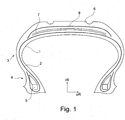
- the FIG. 1 shows a radial cross section through a pneumatic vehicle tire for a passenger car.
- the essential components of which the illustrated pneumatic vehicle tire is composed are a substantially air-impermeable inner layer 1, a carcass 2, which extends in a conventional manner from the zenith of the vehicle pneumatic tire on the side walls 3 to the bead areas 4 and anchored there by wrapping tight bead cores 5 a radially arranged above the carcass profiled tread 6 and arranged between the tread 6 and the carcass 2, two reinforcement layers containing belt 7, which is radially outwardly covered with the belt bandage 8, which comprises a bandage layer 9.
- the belt bandage 8 covers the belt edges and includes strength beams that are wound in parallel in the circumferential direction of the pneumatic vehicle tire along the axial width.
- the FIG. 2 shows a radial cross section through the belt bandage 8 of FIG FIG. 1
- the belt bandage is divided in its axial extent into two side regions 12 and a middle region 10, which each contain a bandage layer part 11, 13.
- the bandage ply 9 has in the center region 10 a bandage ply part 11 whose reinforcements are made of PA6.6, and in each of the side regions 12 a bandage ply part 13 which covers at least the radially outer belt edge and whose reinforcements are made of HMLS PET.
- the reinforcements used are HMLS PET cords made from two 1440 dtex yarns twisted together and PA6.6 cords made from two twisted 1400 dtex yarns. This results in a balanced contour of the bandage layer 9.
- the width of the Bandagenlagenmaschine 13 in the side regions 12 is in each case about 15% of axial width of the belt bandage 8, measured along the contour of the belt bandage. 8
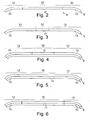
- FIG. 3 shows a radial cross section through a bandage layer 9 of a belt bandage 8 of a further pneumatic vehicle tire according to the invention.
- the bandage layer 9 differs from the in FIG. 2 shown bandage layer 9 characterized in that the width of the Bandagenlagenmaschine 13 occupies in the side regions 12 in each case about 46% of the axial width of the belt bandage 8, measured along the contour of the belt bandage.
- FIGS. 4 to 7 each show two bandage layers 9 a belt bandage 8 of a pneumatic vehicle tire according to the invention.
- radially inner bandage layer 9 is a continuous bandage layer, that is, the strength carrier extending continuously between the side portions 12 and the central region 10. It is in the strength members, for example, cords of PA6.6.
- the radially outer of the shown bandage layers 9 has in the middle region 10 a bandage layer part 11, whose strength members are cords of PA6.6, and in each side region 12 a bandage layer part 13, whose strength members are cords made of HMLS PET.
- Bandage layers 9 shown differ from the in FIG. 4 shown bandage layers 9 by the order of their arrangement in the radial direction.
- FIG. 6 shows two bandage layers 9, both in the central region 10 Bandagenlagteilile whose strength carrier cords are made of PA6.6, and both have in the side regions 12 Bandagenlagenmaschine 13, whose strength carrier cords are made of HMLS PET.
Description
Die Erfindung betrifft einen Fahrzeugluftreifen mit einer Karkasse, einem Laufstreifen, einem zwischen Laufstreifen und Karkasse angeordneten Gürtel sowie einer an der radial äußeren Seite des Gürtels angeordneten, zumindest eine Bandagenlage aufweisende Gürtelbandage mit in Umfangsrichtung aufgebrachten Festigkeitsträgern, wobei die Gürtelbandage in ihrer axialen Ausdehnung in zwei Seitenbereiche und einen Zentralbereich enthaltend jeweils ein Bandagenlagenteil aufgeteilt ist, wobei die Festigkeitsträger des Bandagenlagenteils im Mittenbereich aus Polyamid 6.6 (PA6.6) gebildet sind und wobei die Festigkeitsträger der Bandagenlagenteile in den beiden Seitenbereichen einen höheren Elastizitätsmodul als PA6.6 aufweisen.The invention relates to a pneumatic vehicle tire with a carcass, a tread, arranged between the tread and carcass belt and arranged on the radially outer side of the belt, at least one bandage layer having belt bandage with circumferentially applied strength members, wherein the belt bandage in its axial extent in two Side regions and a central region containing a respective bandage layer part is divided, wherein the strength of the Trägeragenträger Bandagenlagenteils in the middle region of polyamide 6.6 (PA6.6) are formed and wherein the strength of the carrier support web parts parts in the two side regions have a higher modulus than PA6.6.
Festigkeitsträger zur Verstärkung von Fahrzeugluftreifen sind hinreichend bekannt. So ist für Fahrzeugluftreifen bekannt, eine Gürtelbandage zu verwenden, die ein- oder mehrlagig ausgebildet ist, die Gürtelränder abdeckt und parallel und im wesentlichen in Umfangsrichtung verlaufende Festigkeitsträger in Form von im Gummi eingebetteten Festigkeitsträger enthält.Reinforcements for reinforcing pneumatic vehicle tires are well known. Thus, for pneumatic vehicle tires is known to use a belt bandage, which is formed in one or more layers, covering the belt edges and parallel and extending substantially in the circumferential direction of the strength member in the form of embedded in the rubber reinforcement.
Die Gürtelbandage wird bei der Reifenherstellung in Form von Lagen, Streifen oder Einzel-Festigkeitsträgern mit in eine unvulkanisierte Kautschukmischung eingebetteten Festigkeitsträgern aufgebracht, die auf den Gürtel gewickelt oder gespult werden. Die Festigkeitsträger werden vorher entweder in Kautschuk eingebettet, indem eine Schar von im Wesentlichen parallel liegenden fadenförmigen Festigkeitsträgern, die in der Regel thermisch und/oder zur besseren Haftung am einbettenden Gummi in einer der fachkundigen Person bekannten Art mit einer Imprägnierung vorbehandelt sind, in Längsrichtung einen Kalander oder einen Extruder zur Ummantelung mit der Kautschukmischung durchläuft. Oder aber es werden Festigkeitsträger aufgebracht, die klebrig imprägniert sind und ohne eine kalandrierte Haftmischung verarbeitet werden können.The belt bandage is applied in the manufacture of tires in the form of layers, strips or individual reinforcements with embedded in an unvulcanized rubber compound reinforcing agents that are wound or wound on the belt. The reinforcing members are previously embedded either in rubber by a longitudinally one set of substantially parallel filiform reinforcing members, which are usually pretreated with a thermal impregnation and / or for better adhesion to the embedding rubber in a known manner Calender or an extruder to coat with the rubber mixture passes. Or else strength carriers are applied, which are tacky impregnated and can be processed without a calendered adhesive mixture.
Diese Gürtelbandage dient dazu, insbesondere im Hochgeschwindigkeitseinsatz, eine Erhebung des Reifen durch die im Fahrbetrieb auftretenden Fliehkräfte zu begrenzen. Zudem sollen die Festigkeitsträger der Gürtelbandage die Gürtellagen, insbesondere die Gürtelkanten für die Schnelllauffestigkeit und Dauerhaltbarkeit niederhalten. Hierfür müssen in den Schulterbereichen des Fahrzeugluftreifens größere Kräfte gebunden werden als im Mittenbereich.This belt bandage serves, in particular in high-speed deployment, to limit an elevation of the tire due to the centrifugal forces occurring during driving. In addition, the reinforcements of the belt bandage should hold down the belt layers, in particular the belt edges for high-speed stability and durability. For this purpose, larger forces must be bound in the shoulder regions of the pneumatic vehicle tire than in the middle region.
Die Reifenentwicklung geht dahin, die Schnelllauffestigkeit und Dauerhaltbarkeit der Fahrzeugluftreifen zu verbessern.Tire development tends to improve the high speed durability and durability of the pneumatic vehicle tires.
Aus der
Die Materialien PEN und Aramid sowie Hybridcorde enthaltend Aramid sind allerdings in ihrer Anschaffung kostenintensiv. Zudem zeigen sich Festigkeitsträgerlagen enthaltend Festigkeitsträger aus Aramid während des Reifenaufbaus als nachteilig, weil diese zu geringe Schrumpfkräfte aufweisen, was durch Relaxation überkompensiert wird. Aramid weist zudem eine geringe Ermüdungsbeständigkeit sowie eine schlechte Haftung zur elastomeren Mischung auf. Diese Aspekte können sich nachteilig auf die Dauerhaltbarkeit eines Fahrzeugluftreifens aufweisend Festigkeitsträger enthaltend Aramid auswirken. Auch sind Corde und Hybridcorde enthaltend Aramid schwer zu schneiden und verlangen aufwändige Maßnahmen und/oder häufiges Schärfen bzw. Ersetzen des Schneidewerkzeugs. Die Ablängung und Verarbeitung einer Festigkeitsträgerlage aufweisend Corde oder Hybridcorde enthaltend Aramid ist somit nachteilig.However, the materials PEN and aramid as well as hybrid cords containing aramid are expensive to buy. In addition, reinforcement layers comprising aramid reinforcement during tire construction are disadvantageous because they have too low shrinkage forces, which is overcompensated by relaxation. Aramid also has a low Fatigue resistance and poor adhesion to the elastomeric mixture on. These aspects may adversely affect the durability of a pneumatic vehicle tire having strength members containing aramid. Also, cords and hybrid cords containing aramid are difficult to cut and require elaborate measures and / or frequent sharpening or replacement of the cutting tool. The cutting and processing of a reinforcement layer comprising cords or hybrid cords containing aramid is thus disadvantageous.
Aus der
Aus der
Es ist daher die Aufgabe der vorliegenden Erfindung, einen kostengünstigeren Fahrzeugluftreifen bereitzustellen, der eine sehr gute Dauerhaltbarkeit und Schnelllauffestigkeit aufweist und der auf einfache Art und Weise gefertigt werden kann.It is therefore the object of the present invention to provide a cheaper vehicle pneumatic tire, which has a very good durability and high speed performance and can be manufactured in a simple manner.
Gemäß eines ersten Aspekts der vorliegenden Erfindung wird die Aufgabe dadurch gelöst, dass die Festigkeitsträger der Bandagenlagenteile in den beiden Seitenbereichen aus HMLS PET gebildet sind.According to a first aspect of the present invention, the object is achieved in that the strength members of the bandage ply parts are formed in the two side regions of HMLS PET.
Es ist somit ein Fahrzeugluftreifen geschaffen, dessen Gürtelbandage in ihrem Mittenbereich ein Bandagenlagenteil aufweist, dessen Festigkeitsträger aus PA6.6 gebildet sind, sowie in jedem Seitenbereich ein Bandagenlagenteil aufweist, deren Festigkeitsträger aus HMLS PET gebildet sind.Thus, a pneumatic vehicle tire is provided whose belt bandage has in its central region a bandage layer part whose reinforcements are formed of PA6.6, and in each side region has a bandage layer part whose reinforcements are made of HMLS PET.
Bei dem HMLS PET handelt es sich um ein sogenanntes High Modulus Low Shrinkage Polyethylenterephthalat (HMLS PET). Ein solcher Festigkeitsträger sollte dabei für die Anwendung im Reifen einen Schrumpf bei 180°C gemäß ASTM D 855 2% ± 1,0% aufweisen. Weiter soll der Festigkeitsträger bei 160°C eine Zugfestigkeit von über 0,35 cN/dtex bei 2% Dehnung, bei 4% Dehnung eine Zugfestigkeit von über 0,70 cN/dtex und bei 6% Dehnung eine Zugfestigkeit von über 1,20 cN/dtex aufweisen.The HMLS PET is a so-called High Modulus Low Shrinkage Polyethylene Terephthalate (HMLS PET). Such a reinforcement should have a shrinkage at 180 ° C according to ASTM D 855 2% ± 1.0% for use in tires. Furthermore, the strength element should have a tensile strength of more than 0.35 cN / dtex at 2% elongation at 160 ° C., a tensile strength of more than 0.70 cN / dtex at 4% elongation and a tensile strength of more than 1.20 cN at 6% elongation / dtex.
Überraschenderweise wurde gefunden, dass ein solcher Fahrzeugluftreifen kostengünstiger ist und gleichzeitig eine sehr gute Dauerhaltbarkeit und Schnelllauffestigkeit aufweist.Surprisingly, it has been found that such a pneumatic vehicle tire is cheaper and at the same time has a very good durability and high-speed stability.
Das Schneiden bzw. Ablängen von Festigkeitsträgern aus HMLS PET ist einfacher und als das Schneiden bzw. Ablängen von Festigkeitsträgern enthaltend Aramid. Hierdurch werden aufwändige Maßnahmen und zusätzliche Prozesse vermieden und der Fahrzeugluftreifen kann auf einfache Art und Weise gefertigt werden.The cutting or cutting of reinforcements made of HMLS PET is simpler and than the cutting or cutting to length of reinforcements containing aramid. As a result, complex measures and additional processes are avoided and the pneumatic vehicle tire can be manufactured in a simple manner.
Ein Fahrzeugluftreifen, dessen Gürtelbandage Festigkeitsträger aus HMLS PET aufweist, zeichnet sich durch eine sehr gute Dauerhaltbarkeit aus. Insbesondere weist HMLS PET vorteilhafte Schrumpfeigenschaften, große Ermüdungsbeständigkeit sowie eine sehr gute Haftung zur elastomeren Mischung auf.A pneumatic vehicle tire whose belt bandage comprises HMLS PET reinforcements is characterized by very good durability. In particular, HMLS PET has favorable shrink properties, high fatigue resistance and very good adhesion to the elastomeric blend.
Festigkeitsträger aus HMLS PET weisen einen höheren Elatizitätsmodul auf als das für die Festigkeitsträger des Bandagenlagenteils im Mittenbereich verwendete Polyamid 6.6 (PA6.6). Im Fahrbetrieb, insbesondere im Hochgeschwindigkeitseinsatz erfolgt somit in den Seitenbereichen eine gute Bindung der dort auftretenden Kräfte, wohingegen der Fahrzeugluftreifen durch das niedrigmoduligere PA6.6 im Mittenbereich eine runde Kontur entwickelt und somit positive Hochgeschwindigkeitseigenschaften aufweist. Eine solche Gürtelbandage wirkt sich somit positiv auf die Schnelllauffestigkeit und Dauerhaltbarkeit des Fahrzeugluftreifens aus.Reinforcements made of HMLS PET have a higher modulus of elasticity than polyamide 6.6 (PA6.6) used for the reinforcements of the middle part of the bandage. When driving, especially in high-speed deployment thus takes place in the side areas a good bond the forces occurring there, whereas the pneumatic vehicle tire developed by the lower-modulus PA6.6 in the central region a round contour and thus has positive high-speed properties. Such a belt bandage thus has a positive effect on the high-speed stability and durability of the pneumatic vehicle tire.
Zudem sind Festigkeitsträger aus HMLS PET in der Regel kostengünstiger und weisen eine bessere Marktverfügbarkeit auf als Festigkeitsträger aus PEN oder Festigkeitsträger enthaltend Aramid.In addition, reinforcements made of HMLS PET are generally more cost-effective and have better market availability than reinforcements made of PEN or reinforcements containing aramid.
Somit ist ein schnelllauffester und dauerhaltbarer Fahrzeugluftreifen mit einer Gürtelbandage bereitgestellt, welcher kostengünstiger ist und auf einfache Art und Weise gefertigt werden kann.Thus, a high-speed and durable vehicle tire is provided with a belt bandage, which is cheaper and can be manufactured in a simple manner.
Um eine zuverlässige Haftung eines Festigkeitsträgers zum Gummi zu gewährleisten, ist es zweckmäßig, den Festigkeitsträger mit einer Haftimprägnierung, z.B. mit einem RFL-Dip im 1- oder 2-Bad-Verfahren, zu versehen.In order to ensure a reliable adhesion of a reinforcing agent to the rubber, it is expedient to provide the reinforcing agent with an adhesive impregnation, e.g. with an RFL dip in 1-bath or 2-bath process.
Die Gürtelbandage deckt zumindest die radial äußeren Gürtelkanten ab. Die Bandagenlagenteile der Gürtelbandage werden bei der Herstellung des Fahrzeugluftreifens nacheinander oder gleichzeitig aufgebracht, bevorzugt gewickelt oder gespult. Bandagenlagenteile eines Seitenbereichs und des Mittenbereichs einer Bandagenlage werden dabei in axialer Richtung kontaktierend, überlappend oder beabstanded, insbesondere mit einem Überlapp oder Abstand von etwa einer Gummierungsdicke, aufgebracht. Eine hierbei entstehende Lücke zwischen den Bandagenlagenteilen in axialer Richtung wird im weiteren Herstellungsprozess des Fahrzeugluftreifens durch den Gummi der die Lücke umgebenden Bauteile gefüllt. Im fertigen Fahrzeugluftreifen wird dieser Gummi im Folgenden dem dem axial innen liegenden Bandagenlagenteil zugerechnet. Zwei aneinander angrenzende Bandagenlagenteile können den selben Festigkeitsträger aufweisen, welcher durchgehend über die gesamte axiale Breite der beiden Bandagenlagenteile aufgebracht ist.The belt bandage covers at least the radially outer belt edges. The Bandagenlagenteile the belt bandage are applied in the manufacture of the pneumatic vehicle tire sequentially or simultaneously, preferably wound or wound. Bandage ply parts of a side region and of the middle region of a bandage ply are applied in the axial direction in a contacting, overlapping or spaced manner, in particular with an overlap or distance of approximately one rubberizing thickness. A resulting gap between the bandage layer parts in the axial direction is filled in the further manufacturing process of the pneumatic vehicle tire by the rubber surrounding the gap components. In the finished pneumatic vehicle tire, this rubber is attributed below to the axially inner bandage layer part. Two adjacent bandage ply members may have the same strength member which is applied continuously over the entire axial width of the two Bandagenlagenteile.
Vorteilhaft ist es, wenn die Gürtelbandage eine Bandagenlage aufweist, die im Mittenbereich ein Bandagenlagenteil mit Festigkeitsträgern aus PA6.6 und in jedem der zwei Seitenbereiche ein Bandagenlagenteil mit Festigkeitsträgern aus HMLS PET aufweist. Ein Fahrzeugluftreifen mit einer Gürtelbandage enthaltend eine solche Bandagenlage weist eine gute Schnelllauffestigkeit und verbesserte Dauerhaltbarkeit auf.It is advantageous if the belt bandage has a bandage layer which has a bandage layer part with reinforcements made of PA6.6 in the center area and a bandage layer part with reinforcements made of HMLS PET in each of the two side areas. A pneumatic vehicle tire with a belt bandage containing such a bandage ply has good high speed durability and improved durability.
Zweckmäßig ist es, wenn die Gürtelbandage eine weitere Bandagenlage aufweist. Die weitere Bandagenlage kann radial außerhalb oder radial innerhalb der Bandagenlage enthaltend Bandagenlagenteile gemäß der Erfindung angeordnet sein. Die Festigkeitsträger der weiteren Bandagenlage können alle aus einem Material, insbesondere aus PA6.6, gebildet sein. Die Festigkeitsträger der weiteren Bandagenlage können sich aber auch von Bandagenlagenteil zu Bandagenlagenteil in ihrem Material unterscheiden.It is expedient if the belt bandage has a further bandage layer. The further bandage ply can be arranged radially outside or radially inside the bandage ply comprising bandage ply parts according to the invention. The reinforcements of the further bandage layer can all be formed from one material, in particular PA6.6. However, the reinforcing elements of the further bandage layer may also differ from bandage ply part to bandage ply part in their material.
Zweckmäßig ist es hierbei, wenn die erste und/oder die zweite Bandagenlage, insbesondere die radial innere Bandagenlage, sowohl im Mittenbereich als auch in beiden Seitenbereichen jeweils ein Bandagenlagenteil aufweist. Die Festigkeitsträger der Bandagenlagenteile einer Bandagenlage können alle aus demselben Material gebildet sein oder sich in ihrem Material unterscheiden. Bevorzugt ist ein Ausführungsbeispiel, bei dem die radial innere Bandagenlage im Mittenbereich wie auch in den Seitenbereichen Bandagenlagenteile aufweist, wobei die Festigkeitsträger aus PA6.6 gebildet sind und durchgehend über die gesamte axiale Erstreckung der Bandagenlage aufgebracht sind.It is expedient in this case if the first and / or the second bandage ply, in particular the radially inner bandage ply, has a bandage ply portion both in the center region and in both side regions. The strength members of the bandage ply portions of a bandage ply may all be formed of the same material or differ in their material. Preferred is an embodiment in which the radially inner bandage layer has in the middle region as well as in the side regions Bandagenlagenteile, wherein the strength members are formed of PA6.6 and are applied continuously over the entire axial extent of the bandage layer.
Vorteilhaft ist es, wenn jeder der beiden Seitenbereiche eine axiale Breite von 3 % bis 47 %, insbesondere von 5 % bis 30 %, insbesondere von 10 % bis 20 %, der axialen Breite der Gürtelbandage einnimmt, gemessen entlang der Kontur der Gürtelbandage. Eine solche Gürtelbandage gewährleistet, dass die Gürtelkanten bei der Vulkanisation und im Fahrbetrieb optimal niedergedrückt werden. Ein Fahrzeugluftreifen aufweisend eine solche Gürtelbandage weist somit eine optimale Dauerhaltbarkeit und Schnelllauffestigkeit auf.It is advantageous if each of the two side regions has an axial width of 3% to 47%, in particular of 5% to 30%, in particular of 10% to 20%, of the axial width of the belt bandage, measured along the contour of the belt bandage. Such a belt bandage ensures that the belt edges are optimally depressed during vulcanization and driving. A pneumatic vehicle tire having such a belt bandage thus has optimum durability and high speed stability.
Es ist vorteilhaft, wenn die Festigkeitsträger Garne und/oder Corde sind. Garne und/oder Corde aus HMLS PET und/oder PA6.6 sind kostengünstige Festigkeitsträger und weisen eine hohe Marktverfügbarkeit auf.It is advantageous if the reinforcements are yarns and / or cords. HMLS PET and / or PA6.6 yarns and / or cords are cost-effective reinforcements and have high market availability.
Im Rahmen der vorliegenden Erfindung stellt ein "Cord" ein linienförmiges Gebilde dar, das aus zwei oder mehr miteinander verdrehten Garnen bestehen. Ein "Garn" ist ein linienförmiges Gebilde mehreren Fasern.In the context of the present invention, a "cord" represents a linear structure consisting of two or more twisted yarns. A "yarn" is a linear structure of several fibers.
Vorteilhaft ist es, wenn die Festigkeitsträger Garne und/oder Corde sind, wobei die Feinheit der Garne und/oder der Garne der Korde 200 dtex bis 2200 dtex beträgt. Bei einer Feinheit von weniger als 200 dtex wäre eine ausreichende Festigkeit nicht mehr gegeben, während eine Feinheit von mehr als 2200 dtex durch unnötig viel Material Nachteile mit sich bringt, wie z.B. Rollwiderstands-Nachteile des Fahrzeugluftreifens. Bevorzugt weisen die Garne eine Feinheit von 700 dtex bis 1800 dtex auf.It is advantageous if the reinforcements are yarns and / or cords, wherein the fineness of the yarns and / or the yarns of the cords is 200 dtex to 2200 dtex. With a fineness of less than 200 dtex, sufficient strength would no longer be present, while a fineness of more than 2200 dtex would entail disadvantages due to unnecessarily much material, e.g. Rolling resistance disadvantages of the pneumatic vehicle tire. The yarns preferably have a fineness of 700 dtex to 1800 dtex.
Gemäß einer vorteilhaften Weiterbildung der Erfindung weisen die Corde aus HMLS PET ein, zwei oder mehr solcher Garne auf und die Corde aus PA6.6 ein, zwei oder mehr solcher Garne auf. Besonders bevorzugt werden Corde aus HMLS PET aus zwei miteinander endverdrehten Garnen der Feinheit 1440 dtex sowie Corde aus PA6.6 aus zwei miteinander endverdrehten Garnen der Feinheit 1400 dtex oder 940 dtex eingesetzt.According to an advantageous development of the invention, the cords of HMLS PET comprise one, two or more such yarns and the cords of PA6.6 one, two or more such yarns. Cords made of HMLS PET are particularly preferably made from two 1440 dtex yarns twisted together with one another and cords made of PA6.6 from two end-twisted yarns having a fineness of 1400 dtex or 940 dtex.
Gemäß eines weiteren Aspekts der vorliegenden Erfindung werden in einem Verfahren zur Herstellung eines Fahrzeugluftreifens die Festigkeitsträger des Bandagenlagenteils im Mittenbereich und die Festigkeitsträger der Bandagenlagenteile in den Seitenbereichen mit gleicher Vorspannung aufgebracht. Die Festigkeitsträger werden insbesondere gewickelt oder gespult. Die Zugspannung der Festigkeitsträger wird durch die Regelung der Vorspannung gezielt eingestellt. Die Schnelllaufeigenschaften sowie die Dauerhaltbarkeit eines solchen Fahrzeugluftreifens können kostengünstig auf einfache Art und Weise gezielt eingestellt und erhöht werden.According to a further aspect of the present invention, in a method for producing a pneumatic vehicle tire, the strength members of the bandage layer part are applied in the middle region, and the strength carriers of the bandage layer parts in the side regions are applied with the same pretension. The strength members are in particular wound or wound. The tensile stress of the reinforcement is adjusted by controlling the bias voltage targeted. The high-speed properties and the durability of such a pneumatic vehicle tire can be set and increased cost-effectively in a simple manner.
Weiter ist es vorteilhaft, wenn die Festigkeitsträger des Bandagenlagenteils im Mittenbereich mit einer anderen Vorspannung als die Festigkeitsträger der Bandagenlagenteile in den Seitenbereichen aufgebracht sind. Die Festigkeitsträger werden insbesondere gewickelt oder gespult. Die Zugspannung der Festigkeitsträger in den unterschiedlichen Bandagenlagenteilen werden somit durch die Regelung der Vorspannung gezielt auf die unterschiedlichen Ansprüche der unterschiedlichen Bandagenlagenteile eingestellt. Hierdurch erfolgt kostengünstig auf einfache Art und Weise eine weitere gezielte Optimierung der Schnelllaufeigenschaften sowie die Dauerhaltbarkeit eines solchen Fahrzeugluftreifens. Der Fahrzeugluftreifen wird mit einfachen Mitteln den unterschiedlichen Anforderungen, insbesondere bei unterschiedlichem Reifenaufbau und/oder Einsatzbereich, angepasst.Further, it is advantageous if the strength carrier of the Bandagenlagenteils are applied in the central region with a different bias than the strength carrier of the Bandagenlagenteile in the side regions. The strength members are in particular wound or wound. The tension of the strength members in the different bandage layer parts are thus adjusted by the regulation of the bias targeted to the different requirements of the different bandage layer parts. As a result, a further targeted optimization of the high-speed properties and the durability of such a pneumatic vehicle tire are carried out inexpensively in a simple manner. The pneumatic vehicle tire is adapted by simple means the different requirements, in particular with different tire structure and / or application.
Bei dem erfindungsgemäßen Fahrzeugluftreifen handelt sich vorzugsweise um einen PKW-Reifen oder einen Nutzfahrzeugreifen.The pneumatic vehicle tire according to the invention is preferably a passenger tire or a commercial vehicle tire.
Weitere Merkmale, Vorteile und Einzelheiten der Erfindung werden nun anhand der Figuren, die schematische Ausführungsbeispiele darstellen, näher beschrieben. Dabei zeigt die:
-
Fig. 1 einen Radialschnitt durch einen Fahrzeugluftreifen; -
Fig. 2 und Fig. 3 jeweils eine Bandagenlage einer Gürtelbandage eines Fahrzeugluftreifens gemäß der Erfindung; -
Fig. 4 bis Fig. 6 jeweils zwei Bandagenlagen einer Gürtelbandage eines Fahrzeugluftreifens gemäß der Erfindung.
-
Fig. 1 a radial section through a pneumatic vehicle tire; -
Fig. 2 and Fig. 3 each a bandage layer of a belt bandage of a pneumatic vehicle tire according to the invention; -
Fig. 4 to Fig. 6 two bandage layers of a belt bandage of a pneumatic vehicle tire according to the invention.
Die
Die
Die
Die
Die in
Die in
- 11
- Innenschichtinner layer
- 22
- Karkassecarcass
- 33
- SeitenwandSide wall
- 44
- Wulstbereichbead
- 55
- Wulstkernbead
- 66
- Laufstreifentread
- 77
- Gürtelbelt
- 88th
- Gürtelbandagebelt bandage
- 99
- Bandagenlagebandage ply
- 1010
- Mittenbereichmid-range
- 1111
- Bandagenlagenteil im MittenbereichBandage layer part in the middle area
- 1212
- Seitenbereichpage range
- 1313
- Bandagenlagenteil im SeitenbereichBandage layer part in the side area
- rRrR
- radiale Richtungradial direction
- aRaR
- axiale Richtungaxial direction
Claims (7)
- Pneumatic vehicle tyre with a carcass (2), a tread rubber (6), a breaker belt (7), arranged between the tread rubber (6) and the carcass (2), and also a belt bandage (8), which is arranged on the radially outer side of the breaker belt (7), comprises at least one bandage ply (9) and has reinforcing elements applied in the circumferential direction, the belt bandage (8) being divided in its axial extent into two side regions (12) and a middle region (10), each comprising a bandage ply part (11), (13), the reinforcing elements of the bandage ply part (11) in the middle region (10) being formed from PA 6.6 and the reinforcing elements of the bandage ply parts (13) in the two side regions (12) having a higher modulus of elasticity than PA 6.6,
characterized in that
the reinforcing elements of the bandage ply parts (13) in the two side regions (12) are formed from HMLS PET. - Pneumatic vehicle tyre according to Claim 1, characterized in that the belt bandage (8) comprises a bandage ply (9), which has in the middle region (10) a bandage ply part (11) with reinforcing elements of PA 6.6 and in each of the two side regions (12) a bandage ply part (13) with reinforcing elements of HMLS PET.
- Pneumatic vehicle tyre according to at least one of the preceding claims, characterized in that each of the two side regions (12) assumes an axial width of 3% to 47%, in particular of 5% to 30%, in particular of 10% to 20%, of the axial width of the belt bandage (8), measured along the contour of the belt bandage (8) .
- Pneumatic vehicle tyre according to at least one of the preceding claims, characterized in that the reinforcing elements are yarns and/or cords.
- Pneumatic vehicle tyre according to Claim 4, characterized in that the reinforcing elements are yarns and/or cords, the fineness of the yarns and/or of the yarns of the cords being 200 dtex to 2200 dtex, in particular 700 dtex to 1800 dtex.
- Method for producing a pneumatic vehicle tyre according to at least one of the preceding claims, characterized in that the reinforcing elements of the bandage ply part (11) in the middle region (10) and the reinforcing elements of the bandage ply parts (13) in the side regions (12) are applied with the same prestress.
- Method for producing a pneumatic vehicle tyre according to at least one of Claims 1 to 5, characterized in that the reinforcing elements of the bandage ply part (11) in the middle region (10) are applied with a different prestress than the reinforcing elements of the bandage ply parts (13) in the side regions (12).
Applications Claiming Priority (1)
| Application Number | Priority Date | Filing Date | Title |
|---|---|---|---|
| DE102013108052.9A DE102013108052A1 (en) | 2013-07-26 | 2013-07-26 | Vehicle tires |
Publications (2)
| Publication Number | Publication Date |
|---|---|
| EP2829420A1 EP2829420A1 (en) | 2015-01-28 |
| EP2829420B1 true EP2829420B1 (en) | 2019-03-13 |
Family
ID=50685834
Family Applications (1)
| Application Number | Title | Priority Date | Filing Date |
|---|---|---|---|
| EP14168048.8A Active EP2829420B1 (en) | 2013-07-26 | 2014-05-13 | Pneumatic tyres for a vehicle |
Country Status (3)
| Country | Link |
|---|---|
| EP (1) | EP2829420B1 (en) |
| DE (1) | DE102013108052A1 (en) |
| ES (1) | ES2728506T3 (en) |
Families Citing this family (1)
| Publication number | Priority date | Publication date | Assignee | Title |
|---|---|---|---|---|
| DE102018206562A1 (en) * | 2018-04-27 | 2019-10-31 | Continental Reifen Deutschland Gmbh | Vehicle tires |
Family Cites Families (4)
| Publication number | Priority date | Publication date | Assignee | Title |
|---|---|---|---|---|
| DE4429899A1 (en) * | 1994-08-23 | 1996-02-29 | Sp Reifenwerke Gmbh | Pneumatic tyre breaker for light tyres |
| JP3950088B2 (en) * | 2003-07-24 | 2007-07-25 | 住友ゴム工業株式会社 | Pneumatic radial tire |
| JP4723198B2 (en) | 2004-03-22 | 2011-07-13 | 住友ゴム工業株式会社 | Pneumatic tire |
| EP2171139B1 (en) * | 2007-06-20 | 2012-05-23 | Kolon Industries, Inc. | Drawn poly(ethyleneterephthalate) fiber, poly(ethyleneterephthalate) tire-cord, their preparation method and tire comprising the same |
-
2013
- 2013-07-26 DE DE102013108052.9A patent/DE102013108052A1/en not_active Withdrawn
-
2014
- 2014-05-13 ES ES14168048T patent/ES2728506T3/en active Active
- 2014-05-13 EP EP14168048.8A patent/EP2829420B1/en active Active
Non-Patent Citations (1)
| Title |
|---|
| None * |
Also Published As
| Publication number | Publication date |
|---|---|
| ES2728506T3 (en) | 2019-10-25 |
| EP2829420A1 (en) | 2015-01-28 |
| DE102013108052A1 (en) | 2015-01-29 |
Similar Documents
| Publication | Publication Date | Title |
|---|---|---|
| EP3147138B1 (en) | Pneumatic tire and use of a twisted yarn comprising polyamid 6.6 | |
| DE102007025490A1 (en) | Reinforcing layer of hybrid cords for elastomeric products, in particular for the belt bandage of pneumatic vehicle tires | |
| EP3204239B1 (en) | Pneumatic vehicle tyres comprising a belt bandage | |
| EP3218210B1 (en) | Pneumatic vehicle tires | |
| EP2829419B1 (en) | Pneumatic tyres for a vehicle | |
| EP3724003B1 (en) | Reinforcing layer and pneumatic vehicle tyre | |
| EP2113397B1 (en) | Stability beam layout made from hybrid cords for elastomeric products, in particular for the belt of vehicle pneumatic tyres | |
| EP2188137A1 (en) | Belt bandage for a pneumatic vehicle tire and pneumatic vehicle tire, comprising said belt bandage | |
| EP3181374A1 (en) | Reinforcing layer or reinforcing strip for elastomeric products | |
| DE102016202930A1 (en) | Vehicle tires | |
| DE102016223304B4 (en) | 2Vehicle pneumatic tyres | |
| EP2829420B1 (en) | Pneumatic tyres for a vehicle | |
| EP3784502B1 (en) | Pneumatic tyre for a vehicle | |
| EP3433110A1 (en) | Pneumatic vehicle tyres | |
| DE102007025489A1 (en) | Reinforcing layer of hybrid cords for elastomeric products, in particular for the belt bandage of pneumatic vehicle tires | |
| EP2019757B1 (en) | Pneumatic vehicle tyre with belt bandage | |
| EP3715144B1 (en) | Pneumatic vehicle tyre comprising a belt press-on band with a hybrid cord comprising pa 6.6 and pet | |
| DE102017215655A1 (en) | Pneumatic vehicle tire having a belt bandage | |
| EP3792080B1 (en) | Pneumatic tyre | |
| EP4177079A1 (en) | Reinforcement layer for elastomeric products and pneumatic vehicle tyres | |
| DE102021205071A1 (en) | Process for the production of a spool bandage | |
| EP3416833A1 (en) | Pneumatic vehicle tyres | |
| DE102017217437A1 (en) | Reinforcement member for a reinforcement layer | |
| DE102010000563A1 (en) | Belt bandage for pneumatic tire of car, has stripes that are arranged in tire circumferential direction over axial width of bandage, whose longitudinal axes are inclined at preset angle with respect to tire circumferential direction | |
| DE102009044216A1 (en) | Belt strap for vehicle tire, comprises multiple reinforcements that are arranged substantially parallel to each other, where reinforcements are arranged within belt strap |
Legal Events
| Date | Code | Title | Description |
|---|---|---|---|
| 17P | Request for examination filed |
Effective date: 20140513 |
|
| AK | Designated contracting states |
Kind code of ref document: A1 Designated state(s): AL AT BE BG CH CY CZ DE DK EE ES FI FR GB GR HR HU IE IS IT LI LT LU LV MC MK MT NL NO PL PT RO RS SE SI SK SM TR |
|
| AX | Request for extension of the european patent |
Extension state: BA ME |
|
| PUAI | Public reference made under article 153(3) epc to a published international application that has entered the european phase |
Free format text: ORIGINAL CODE: 0009012 |
|
| R17P | Request for examination filed (corrected) |
Effective date: 20150728 |
|
| RBV | Designated contracting states (corrected) |
Designated state(s): AL AT BE BG CH CY CZ DE DK EE ES FI FR GB GR HR HU IE IS IT LI LT LU LV MC MK MT NL NO PL PT RO RS SE SI SK SM TR |
|
| STAA | Information on the status of an ep patent application or granted ep patent |
Free format text: STATUS: EXAMINATION IS IN PROGRESS |
|
| 17Q | First examination report despatched |
Effective date: 20180525 |
|
| GRAP | Despatch of communication of intention to grant a patent |
Free format text: ORIGINAL CODE: EPIDOSNIGR1 |
|
| STAA | Information on the status of an ep patent application or granted ep patent |
Free format text: STATUS: GRANT OF PATENT IS INTENDED |
|
| INTG | Intention to grant announced |
Effective date: 20181206 |
|
| RIN1 | Information on inventor provided before grant (corrected) |
Inventor name: BLUEMEL, VIKTOR Inventor name: REESE, WOLFGANG |
|
| GRAS | Grant fee paid |
Free format text: ORIGINAL CODE: EPIDOSNIGR3 |
|
| GRAA | (expected) grant |
Free format text: ORIGINAL CODE: 0009210 |
|
| STAA | Information on the status of an ep patent application or granted ep patent |
Free format text: STATUS: THE PATENT HAS BEEN GRANTED |
|
| AK | Designated contracting states |
Kind code of ref document: B1 Designated state(s): AL AT BE BG CH CY CZ DE DK EE ES FI FR GB GR HR HU IE IS IT LI LT LU LV MC MK MT NL NO PL PT RO RS SE SI SK SM TR |
|
| REG | Reference to a national code |
Ref country code: GB Ref legal event code: FG4D Free format text: NOT ENGLISH |
|
| REG | Reference to a national code |
Ref country code: CH Ref legal event code: EP Ref country code: AT Ref legal event code: REF Ref document number: 1107179 Country of ref document: AT Kind code of ref document: T Effective date: 20190315 |
|
| REG | Reference to a national code |
Ref country code: IE Ref legal event code: FG4D Free format text: LANGUAGE OF EP DOCUMENT: GERMAN |
|
| REG | Reference to a national code |
Ref country code: DE Ref legal event code: R096 Ref document number: 502014011081 Country of ref document: DE |
|
| REG | Reference to a national code |
Ref country code: NL Ref legal event code: MP Effective date: 20190313 |
|
| REG | Reference to a national code |
Ref country code: LT Ref legal event code: MG4D |
|
| PG25 | Lapsed in a contracting state [announced via postgrant information from national office to epo] |
Ref country code: FI Free format text: LAPSE BECAUSE OF FAILURE TO SUBMIT A TRANSLATION OF THE DESCRIPTION OR TO PAY THE FEE WITHIN THE PRESCRIBED TIME-LIMIT Effective date: 20190313 Ref country code: LT Free format text: LAPSE BECAUSE OF FAILURE TO SUBMIT A TRANSLATION OF THE DESCRIPTION OR TO PAY THE FEE WITHIN THE PRESCRIBED TIME-LIMIT Effective date: 20190313 Ref country code: SE Free format text: LAPSE BECAUSE OF FAILURE TO SUBMIT A TRANSLATION OF THE DESCRIPTION OR TO PAY THE FEE WITHIN THE PRESCRIBED TIME-LIMIT Effective date: 20190313 Ref country code: NO Free format text: LAPSE BECAUSE OF FAILURE TO SUBMIT A TRANSLATION OF THE DESCRIPTION OR TO PAY THE FEE WITHIN THE PRESCRIBED TIME-LIMIT Effective date: 20190613 |
|
| PG25 | Lapsed in a contracting state [announced via postgrant information from national office to epo] |
Ref country code: BG Free format text: LAPSE BECAUSE OF FAILURE TO SUBMIT A TRANSLATION OF THE DESCRIPTION OR TO PAY THE FEE WITHIN THE PRESCRIBED TIME-LIMIT Effective date: 20190613 Ref country code: RS Free format text: LAPSE BECAUSE OF FAILURE TO SUBMIT A TRANSLATION OF THE DESCRIPTION OR TO PAY THE FEE WITHIN THE PRESCRIBED TIME-LIMIT Effective date: 20190313 Ref country code: LV Free format text: LAPSE BECAUSE OF FAILURE TO SUBMIT A TRANSLATION OF THE DESCRIPTION OR TO PAY THE FEE WITHIN THE PRESCRIBED TIME-LIMIT Effective date: 20190313 Ref country code: HR Free format text: LAPSE BECAUSE OF FAILURE TO SUBMIT A TRANSLATION OF THE DESCRIPTION OR TO PAY THE FEE WITHIN THE PRESCRIBED TIME-LIMIT Effective date: 20190313 Ref country code: GR Free format text: LAPSE BECAUSE OF FAILURE TO SUBMIT A TRANSLATION OF THE DESCRIPTION OR TO PAY THE FEE WITHIN THE PRESCRIBED TIME-LIMIT Effective date: 20190614 Ref country code: NL Free format text: LAPSE BECAUSE OF FAILURE TO SUBMIT A TRANSLATION OF THE DESCRIPTION OR TO PAY THE FEE WITHIN THE PRESCRIBED TIME-LIMIT Effective date: 20190313 |
|
| REG | Reference to a national code |
Ref country code: ES Ref legal event code: FG2A Ref document number: 2728506 Country of ref document: ES Kind code of ref document: T3 Effective date: 20191025 |
|
| PG25 | Lapsed in a contracting state [announced via postgrant information from national office to epo] |
Ref country code: RO Free format text: LAPSE BECAUSE OF FAILURE TO SUBMIT A TRANSLATION OF THE DESCRIPTION OR TO PAY THE FEE WITHIN THE PRESCRIBED TIME-LIMIT Effective date: 20190313 Ref country code: SK Free format text: LAPSE BECAUSE OF FAILURE TO SUBMIT A TRANSLATION OF THE DESCRIPTION OR TO PAY THE FEE WITHIN THE PRESCRIBED TIME-LIMIT Effective date: 20190313 Ref country code: IT Free format text: LAPSE BECAUSE OF FAILURE TO SUBMIT A TRANSLATION OF THE DESCRIPTION OR TO PAY THE FEE WITHIN THE PRESCRIBED TIME-LIMIT Effective date: 20190313 Ref country code: EE Free format text: LAPSE BECAUSE OF FAILURE TO SUBMIT A TRANSLATION OF THE DESCRIPTION OR TO PAY THE FEE WITHIN THE PRESCRIBED TIME-LIMIT Effective date: 20190313 Ref country code: CZ Free format text: LAPSE BECAUSE OF FAILURE TO SUBMIT A TRANSLATION OF THE DESCRIPTION OR TO PAY THE FEE WITHIN THE PRESCRIBED TIME-LIMIT Effective date: 20190313 Ref country code: PT Free format text: LAPSE BECAUSE OF FAILURE TO SUBMIT A TRANSLATION OF THE DESCRIPTION OR TO PAY THE FEE WITHIN THE PRESCRIBED TIME-LIMIT Effective date: 20190713 Ref country code: AL Free format text: LAPSE BECAUSE OF FAILURE TO SUBMIT A TRANSLATION OF THE DESCRIPTION OR TO PAY THE FEE WITHIN THE PRESCRIBED TIME-LIMIT Effective date: 20190313 |
|
| PG25 | Lapsed in a contracting state [announced via postgrant information from national office to epo] |
Ref country code: SM Free format text: LAPSE BECAUSE OF FAILURE TO SUBMIT A TRANSLATION OF THE DESCRIPTION OR TO PAY THE FEE WITHIN THE PRESCRIBED TIME-LIMIT Effective date: 20190313 Ref country code: PL Free format text: LAPSE BECAUSE OF FAILURE TO SUBMIT A TRANSLATION OF THE DESCRIPTION OR TO PAY THE FEE WITHIN THE PRESCRIBED TIME-LIMIT Effective date: 20190313 |
|
| REG | Reference to a national code |
Ref country code: DE Ref legal event code: R097 Ref document number: 502014011081 Country of ref document: DE |
|
| REG | Reference to a national code |
Ref country code: CH Ref legal event code: PL |
|
| PG25 | Lapsed in a contracting state [announced via postgrant information from national office to epo] |
Ref country code: IS Free format text: LAPSE BECAUSE OF FAILURE TO SUBMIT A TRANSLATION OF THE DESCRIPTION OR TO PAY THE FEE WITHIN THE PRESCRIBED TIME-LIMIT Effective date: 20190713 |
|
| PLBE | No opposition filed within time limit |
Free format text: ORIGINAL CODE: 0009261 |
|
| STAA | Information on the status of an ep patent application or granted ep patent |
Free format text: STATUS: NO OPPOSITION FILED WITHIN TIME LIMIT |
|
| PG25 | Lapsed in a contracting state [announced via postgrant information from national office to epo] |
Ref country code: DK Free format text: LAPSE BECAUSE OF FAILURE TO SUBMIT A TRANSLATION OF THE DESCRIPTION OR TO PAY THE FEE WITHIN THE PRESCRIBED TIME-LIMIT Effective date: 20190313 Ref country code: MC Free format text: LAPSE BECAUSE OF FAILURE TO SUBMIT A TRANSLATION OF THE DESCRIPTION OR TO PAY THE FEE WITHIN THE PRESCRIBED TIME-LIMIT Effective date: 20190313 Ref country code: CH Free format text: LAPSE BECAUSE OF NON-PAYMENT OF DUE FEES Effective date: 20190531 Ref country code: LI Free format text: LAPSE BECAUSE OF NON-PAYMENT OF DUE FEES Effective date: 20190531 |
|
| REG | Reference to a national code |
Ref country code: BE Ref legal event code: MM Effective date: 20190531 |
|
| 26N | No opposition filed |
Effective date: 20191216 |
|
| GBPC | Gb: european patent ceased through non-payment of renewal fee |
Effective date: 20190613 |
|
| PG25 | Lapsed in a contracting state [announced via postgrant information from national office to epo] |
Ref country code: LU Free format text: LAPSE BECAUSE OF NON-PAYMENT OF DUE FEES Effective date: 20190513 Ref country code: SI Free format text: LAPSE BECAUSE OF FAILURE TO SUBMIT A TRANSLATION OF THE DESCRIPTION OR TO PAY THE FEE WITHIN THE PRESCRIBED TIME-LIMIT Effective date: 20190313 |
|
| PG25 | Lapsed in a contracting state [announced via postgrant information from national office to epo] |
Ref country code: TR Free format text: LAPSE BECAUSE OF FAILURE TO SUBMIT A TRANSLATION OF THE DESCRIPTION OR TO PAY THE FEE WITHIN THE PRESCRIBED TIME-LIMIT Effective date: 20190313 |
|
| PG25 | Lapsed in a contracting state [announced via postgrant information from national office to epo] |
Ref country code: GB Free format text: LAPSE BECAUSE OF NON-PAYMENT OF DUE FEES Effective date: 20190613 Ref country code: IE Free format text: LAPSE BECAUSE OF NON-PAYMENT OF DUE FEES Effective date: 20190513 |
|
| PG25 | Lapsed in a contracting state [announced via postgrant information from national office to epo] |
Ref country code: BE Free format text: LAPSE BECAUSE OF NON-PAYMENT OF DUE FEES Effective date: 20190531 |
|
| REG | Reference to a national code |
Ref country code: AT Ref legal event code: MM01 Ref document number: 1107179 Country of ref document: AT Kind code of ref document: T Effective date: 20190513 |
|
| PG25 | Lapsed in a contracting state [announced via postgrant information from national office to epo] |
Ref country code: AT Free format text: LAPSE BECAUSE OF NON-PAYMENT OF DUE FEES Effective date: 20190513 |
|
| PG25 | Lapsed in a contracting state [announced via postgrant information from national office to epo] |
Ref country code: CY Free format text: LAPSE BECAUSE OF FAILURE TO SUBMIT A TRANSLATION OF THE DESCRIPTION OR TO PAY THE FEE WITHIN THE PRESCRIBED TIME-LIMIT Effective date: 20190313 |
|
| PG25 | Lapsed in a contracting state [announced via postgrant information from national office to epo] |
Ref country code: HU Free format text: LAPSE BECAUSE OF FAILURE TO SUBMIT A TRANSLATION OF THE DESCRIPTION OR TO PAY THE FEE WITHIN THE PRESCRIBED TIME-LIMIT; INVALID AB INITIO Effective date: 20140513 Ref country code: MT Free format text: LAPSE BECAUSE OF FAILURE TO SUBMIT A TRANSLATION OF THE DESCRIPTION OR TO PAY THE FEE WITHIN THE PRESCRIBED TIME-LIMIT Effective date: 20190313 |
|
| PG25 | Lapsed in a contracting state [announced via postgrant information from national office to epo] |
Ref country code: MK Free format text: LAPSE BECAUSE OF FAILURE TO SUBMIT A TRANSLATION OF THE DESCRIPTION OR TO PAY THE FEE WITHIN THE PRESCRIBED TIME-LIMIT Effective date: 20190313 |
|
| PGFP | Annual fee paid to national office [announced via postgrant information from national office to epo] |
Ref country code: FR Payment date: 20230526 Year of fee payment: 10 Ref country code: DE Payment date: 20230531 Year of fee payment: 10 |
|
| PGFP | Annual fee paid to national office [announced via postgrant information from national office to epo] |
Ref country code: ES Payment date: 20230725 Year of fee payment: 10 |
|
| REG | Reference to a national code |
Ref country code: DE Ref legal event code: R081 Ref document number: 502014011081 Country of ref document: DE Owner name: CONTINENTAL REIFEN DEUTSCHLAND GMBH, DE Free format text: FORMER OWNER: CONTINENTAL REIFEN DEUTSCHLAND GMBH, 30165 HANNOVER, DE |