EP3023236B1 - Method for manufacturing fibre composites and pre-product - Google Patents
Method for manufacturing fibre composites and pre-product Download PDFInfo
- Publication number
- EP3023236B1 EP3023236B1 EP15195422.9A EP15195422A EP3023236B1 EP 3023236 B1 EP3023236 B1 EP 3023236B1 EP 15195422 A EP15195422 A EP 15195422A EP 3023236 B1 EP3023236 B1 EP 3023236B1
- Authority
- EP
- European Patent Office
- Prior art keywords
- spacers
- spacer
- layer
- mould
- fibre
- Prior art date
- Legal status (The legal status is an assumption and is not a legal conclusion. Google has not performed a legal analysis and makes no representation as to the accuracy of the status listed.)
- Active
Links
- 239000000835 fiber Substances 0.000 title claims description 131
- 238000000034 method Methods 0.000 title claims description 44
- 239000002131 composite material Substances 0.000 title claims description 43
- 238000004519 manufacturing process Methods 0.000 title claims description 15
- 125000006850 spacer group Chemical group 0.000 claims description 136
- 239000000463 material Substances 0.000 claims description 33
- 239000004033 plastic Substances 0.000 claims description 29
- 229920003023 plastic Polymers 0.000 claims description 29
- 238000002347 injection Methods 0.000 claims description 21
- 239000007924 injection Substances 0.000 claims description 21
- 238000007493 shaping process Methods 0.000 claims description 9
- 230000006835 compression Effects 0.000 claims description 2
- 238000007906 compression Methods 0.000 claims description 2
- 230000004323 axial length Effects 0.000 claims 1
- 229920005989 resin Polymers 0.000 description 47
- 239000011347 resin Substances 0.000 description 47
- 239000011159 matrix material Substances 0.000 description 21
- 238000009826 distribution Methods 0.000 description 19
- 239000002657 fibrous material Substances 0.000 description 15
- 239000004744 fabric Substances 0.000 description 14
- 239000006260 foam Substances 0.000 description 13
- 238000001764 infiltration Methods 0.000 description 9
- 230000008595 infiltration Effects 0.000 description 9
- 238000001802 infusion Methods 0.000 description 8
- 239000011162 core material Substances 0.000 description 7
- 238000009745 resin transfer moulding Methods 0.000 description 5
- 238000013461 design Methods 0.000 description 4
- 239000002184 metal Substances 0.000 description 4
- 230000035699 permeability Effects 0.000 description 4
- -1 polypropylene Polymers 0.000 description 4
- 239000004753 textile Substances 0.000 description 4
- 238000013459 approach Methods 0.000 description 3
- 238000010276 construction Methods 0.000 description 3
- 238000006073 displacement reaction Methods 0.000 description 3
- 239000011265 semifinished product Substances 0.000 description 3
- 239000004698 Polyethylene Substances 0.000 description 2
- 239000004743 Polypropylene Substances 0.000 description 2
- 238000005429 filling process Methods 0.000 description 2
- 239000011888 foil Substances 0.000 description 2
- 239000003365 glass fiber Substances 0.000 description 2
- 229920001707 polybutylene terephthalate Polymers 0.000 description 2
- 229920000573 polyethylene Polymers 0.000 description 2
- 229920000139 polyethylene terephthalate Polymers 0.000 description 2
- 239000005020 polyethylene terephthalate Substances 0.000 description 2
- 229920001155 polypropylene Polymers 0.000 description 2
- 229920003002 synthetic resin Polymers 0.000 description 2
- 239000000057 synthetic resin Substances 0.000 description 2
- 229920001169 thermoplastic Polymers 0.000 description 2
- 239000012815 thermoplastic material Substances 0.000 description 2
- 239000004416 thermosoftening plastic Substances 0.000 description 2
- 230000008719 thickening Effects 0.000 description 2
- 229920002748 Basalt fiber Polymers 0.000 description 1
- ZOXJGFHDIHLPTG-UHFFFAOYSA-N Boron Chemical compound [B] ZOXJGFHDIHLPTG-UHFFFAOYSA-N 0.000 description 1
- 229920000049 Carbon (fiber) Polymers 0.000 description 1
- 239000004793 Polystyrene Substances 0.000 description 1
- 229920005830 Polyurethane Foam Polymers 0.000 description 1
- 239000004809 Teflon Substances 0.000 description 1
- 229920006362 Teflon® Polymers 0.000 description 1
- 239000000853 adhesive Substances 0.000 description 1
- 238000004026 adhesive bonding Methods 0.000 description 1
- 230000001070 adhesive effect Effects 0.000 description 1
- 229920006231 aramid fiber Polymers 0.000 description 1
- 239000011230 binding agent Substances 0.000 description 1
- 229910052796 boron Inorganic materials 0.000 description 1
- 239000004917 carbon fiber Substances 0.000 description 1
- 239000000919 ceramic Substances 0.000 description 1
- 238000001311 chemical methods and process Methods 0.000 description 1
- 230000001419 dependent effect Effects 0.000 description 1
- 230000000694 effects Effects 0.000 description 1
- 230000005489 elastic deformation Effects 0.000 description 1
- 229920001971 elastomer Polymers 0.000 description 1
- 239000000806 elastomer Substances 0.000 description 1
- 238000004049 embossing Methods 0.000 description 1
- 239000003822 epoxy resin Substances 0.000 description 1
- 239000004794 expanded polystyrene Substances 0.000 description 1
- 238000001125 extrusion Methods 0.000 description 1
- 239000003292 glue Substances 0.000 description 1
- 238000005470 impregnation Methods 0.000 description 1
- VNWKTOKETHGBQD-UHFFFAOYSA-N methane Chemical compound C VNWKTOKETHGBQD-UHFFFAOYSA-N 0.000 description 1
- 229920001778 nylon Polymers 0.000 description 1
- 238000012856 packing Methods 0.000 description 1
- 239000011049 pearl Substances 0.000 description 1
- 239000002985 plastic film Substances 0.000 description 1
- 229920006255 plastic film Polymers 0.000 description 1
- 229920000647 polyepoxide Polymers 0.000 description 1
- 229920000642 polymer Polymers 0.000 description 1
- 229920002223 polystyrene Polymers 0.000 description 1
- 239000011496 polyurethane foam Substances 0.000 description 1
- 239000004800 polyvinyl chloride Substances 0.000 description 1
- 239000011148 porous material Substances 0.000 description 1
- 238000004080 punching Methods 0.000 description 1
- 229920006395 saturated elastomer Polymers 0.000 description 1
- 230000000087 stabilizing effect Effects 0.000 description 1
- 229920001567 vinyl ester resin Polymers 0.000 description 1
Images


Classifications
-
- B—PERFORMING OPERATIONS; TRANSPORTING
- B29—WORKING OF PLASTICS; WORKING OF SUBSTANCES IN A PLASTIC STATE IN GENERAL
- B29C—SHAPING OR JOINING OF PLASTICS; SHAPING OF MATERIAL IN A PLASTIC STATE, NOT OTHERWISE PROVIDED FOR; AFTER-TREATMENT OF THE SHAPED PRODUCTS, e.g. REPAIRING
- B29C70/00—Shaping composites, i.e. plastics material comprising reinforcements, fillers or preformed parts, e.g. inserts
- B29C70/04—Shaping composites, i.e. plastics material comprising reinforcements, fillers or preformed parts, e.g. inserts comprising reinforcements only, e.g. self-reinforcing plastics
- B29C70/28—Shaping operations therefor
- B29C70/40—Shaping or impregnating by compression not applied
- B29C70/42—Shaping or impregnating by compression not applied for producing articles of definite length, i.e. discrete articles
- B29C70/46—Shaping or impregnating by compression not applied for producing articles of definite length, i.e. discrete articles using matched moulds, e.g. for deforming sheet moulding compounds [SMC] or prepregs
- B29C70/467—Shaping or impregnating by compression not applied for producing articles of definite length, i.e. discrete articles using matched moulds, e.g. for deforming sheet moulding compounds [SMC] or prepregs and impregnating the reinforcements during mould closing
-
- B—PERFORMING OPERATIONS; TRANSPORTING
- B29—WORKING OF PLASTICS; WORKING OF SUBSTANCES IN A PLASTIC STATE IN GENERAL
- B29C—SHAPING OR JOINING OF PLASTICS; SHAPING OF MATERIAL IN A PLASTIC STATE, NOT OTHERWISE PROVIDED FOR; AFTER-TREATMENT OF THE SHAPED PRODUCTS, e.g. REPAIRING
- B29C70/00—Shaping composites, i.e. plastics material comprising reinforcements, fillers or preformed parts, e.g. inserts
- B29C70/04—Shaping composites, i.e. plastics material comprising reinforcements, fillers or preformed parts, e.g. inserts comprising reinforcements only, e.g. self-reinforcing plastics
- B29C70/06—Fibrous reinforcements only
- B29C70/08—Fibrous reinforcements only comprising combinations of different forms of fibrous reinforcements incorporated in matrix material, forming one or more layers, and with or without non-reinforced layers
- B29C70/086—Fibrous reinforcements only comprising combinations of different forms of fibrous reinforcements incorporated in matrix material, forming one or more layers, and with or without non-reinforced layers and with one or more layers of pure plastics material, e.g. foam layers
-
- B—PERFORMING OPERATIONS; TRANSPORTING
- B29—WORKING OF PLASTICS; WORKING OF SUBSTANCES IN A PLASTIC STATE IN GENERAL
- B29C—SHAPING OR JOINING OF PLASTICS; SHAPING OF MATERIAL IN A PLASTIC STATE, NOT OTHERWISE PROVIDED FOR; AFTER-TREATMENT OF THE SHAPED PRODUCTS, e.g. REPAIRING
- B29C70/00—Shaping composites, i.e. plastics material comprising reinforcements, fillers or preformed parts, e.g. inserts
- B29C70/04—Shaping composites, i.e. plastics material comprising reinforcements, fillers or preformed parts, e.g. inserts comprising reinforcements only, e.g. self-reinforcing plastics
- B29C70/28—Shaping operations therefor
- B29C70/40—Shaping or impregnating by compression not applied
- B29C70/42—Shaping or impregnating by compression not applied for producing articles of definite length, i.e. discrete articles
- B29C70/44—Shaping or impregnating by compression not applied for producing articles of definite length, i.e. discrete articles using isostatic pressure, e.g. pressure difference-moulding, vacuum bag-moulding, autoclave-moulding or expanding rubber-moulding
- B29C70/443—Shaping or impregnating by compression not applied for producing articles of definite length, i.e. discrete articles using isostatic pressure, e.g. pressure difference-moulding, vacuum bag-moulding, autoclave-moulding or expanding rubber-moulding and impregnating by vacuum or injection
-
- B—PERFORMING OPERATIONS; TRANSPORTING
- B29—WORKING OF PLASTICS; WORKING OF SUBSTANCES IN A PLASTIC STATE IN GENERAL
- B29C—SHAPING OR JOINING OF PLASTICS; SHAPING OF MATERIAL IN A PLASTIC STATE, NOT OTHERWISE PROVIDED FOR; AFTER-TREATMENT OF THE SHAPED PRODUCTS, e.g. REPAIRING
- B29C70/00—Shaping composites, i.e. plastics material comprising reinforcements, fillers or preformed parts, e.g. inserts
- B29C70/04—Shaping composites, i.e. plastics material comprising reinforcements, fillers or preformed parts, e.g. inserts comprising reinforcements only, e.g. self-reinforcing plastics
- B29C70/28—Shaping operations therefor
- B29C70/40—Shaping or impregnating by compression not applied
- B29C70/42—Shaping or impregnating by compression not applied for producing articles of definite length, i.e. discrete articles
- B29C70/46—Shaping or impregnating by compression not applied for producing articles of definite length, i.e. discrete articles using matched moulds, e.g. for deforming sheet moulding compounds [SMC] or prepregs
- B29C70/48—Shaping or impregnating by compression not applied for producing articles of definite length, i.e. discrete articles using matched moulds, e.g. for deforming sheet moulding compounds [SMC] or prepregs and impregnating the reinforcements in the closed mould, e.g. resin transfer moulding [RTM], e.g. by vacuum
-
- B—PERFORMING OPERATIONS; TRANSPORTING
- B29—WORKING OF PLASTICS; WORKING OF SUBSTANCES IN A PLASTIC STATE IN GENERAL
- B29C—SHAPING OR JOINING OF PLASTICS; SHAPING OF MATERIAL IN A PLASTIC STATE, NOT OTHERWISE PROVIDED FOR; AFTER-TREATMENT OF THE SHAPED PRODUCTS, e.g. REPAIRING
- B29C70/00—Shaping composites, i.e. plastics material comprising reinforcements, fillers or preformed parts, e.g. inserts
- B29C70/04—Shaping composites, i.e. plastics material comprising reinforcements, fillers or preformed parts, e.g. inserts comprising reinforcements only, e.g. self-reinforcing plastics
- B29C70/28—Shaping operations therefor
- B29C70/54—Component parts, details or accessories; Auxiliary operations, e.g. feeding or storage of prepregs or SMC after impregnation or during ageing
- B29C70/546—Measures for feeding or distributing the matrix material in the reinforcing structure
- B29C70/547—Measures for feeding or distributing the matrix material in the reinforcing structure using channels or porous distribution layers incorporated in or associated with the product
-
- B—PERFORMING OPERATIONS; TRANSPORTING
- B32—LAYERED PRODUCTS
- B32B—LAYERED PRODUCTS, i.e. PRODUCTS BUILT-UP OF STRATA OF FLAT OR NON-FLAT, e.g. CELLULAR OR HONEYCOMB, FORM
- B32B1/00—Layered products having a non-planar shape
-
- B—PERFORMING OPERATIONS; TRANSPORTING
- B32—LAYERED PRODUCTS
- B32B—LAYERED PRODUCTS, i.e. PRODUCTS BUILT-UP OF STRATA OF FLAT OR NON-FLAT, e.g. CELLULAR OR HONEYCOMB, FORM
- B32B3/00—Layered products comprising a layer with external or internal discontinuities or unevennesses, or a layer of non-planar shape; Layered products comprising a layer having particular features of form
- B32B3/02—Layered products comprising a layer with external or internal discontinuities or unevennesses, or a layer of non-planar shape; Layered products comprising a layer having particular features of form characterised by features of form at particular places, e.g. in edge regions
- B32B3/08—Layered products comprising a layer with external or internal discontinuities or unevennesses, or a layer of non-planar shape; Layered products comprising a layer having particular features of form characterised by features of form at particular places, e.g. in edge regions characterised by added members at particular parts
-
- B—PERFORMING OPERATIONS; TRANSPORTING
- B32—LAYERED PRODUCTS
- B32B—LAYERED PRODUCTS, i.e. PRODUCTS BUILT-UP OF STRATA OF FLAT OR NON-FLAT, e.g. CELLULAR OR HONEYCOMB, FORM
- B32B3/00—Layered products comprising a layer with external or internal discontinuities or unevennesses, or a layer of non-planar shape; Layered products comprising a layer having particular features of form
- B32B3/26—Layered products comprising a layer with external or internal discontinuities or unevennesses, or a layer of non-planar shape; Layered products comprising a layer having particular features of form characterised by a particular shape of the outline of the cross-section of a continuous layer; characterised by a layer with cavities or internal voids ; characterised by an apertured layer
- B32B3/266—Layered products comprising a layer with external or internal discontinuities or unevennesses, or a layer of non-planar shape; Layered products comprising a layer having particular features of form characterised by a particular shape of the outline of the cross-section of a continuous layer; characterised by a layer with cavities or internal voids ; characterised by an apertured layer characterised by an apertured layer, the apertures going through the whole thickness of the layer, e.g. expanded metal, perforated layer, slit layer regular cells B32B3/12
-
- B—PERFORMING OPERATIONS; TRANSPORTING
- B32—LAYERED PRODUCTS
- B32B—LAYERED PRODUCTS, i.e. PRODUCTS BUILT-UP OF STRATA OF FLAT OR NON-FLAT, e.g. CELLULAR OR HONEYCOMB, FORM
- B32B3/00—Layered products comprising a layer with external or internal discontinuities or unevennesses, or a layer of non-planar shape; Layered products comprising a layer having particular features of form
- B32B3/26—Layered products comprising a layer with external or internal discontinuities or unevennesses, or a layer of non-planar shape; Layered products comprising a layer having particular features of form characterised by a particular shape of the outline of the cross-section of a continuous layer; characterised by a layer with cavities or internal voids ; characterised by an apertured layer
- B32B3/28—Layered products comprising a layer with external or internal discontinuities or unevennesses, or a layer of non-planar shape; Layered products comprising a layer having particular features of form characterised by a particular shape of the outline of the cross-section of a continuous layer; characterised by a layer with cavities or internal voids ; characterised by an apertured layer characterised by a layer comprising a deformed thin sheet, i.e. the layer having its entire thickness deformed out of the plane, e.g. corrugated, crumpled
-
- B—PERFORMING OPERATIONS; TRANSPORTING
- B32—LAYERED PRODUCTS
- B32B—LAYERED PRODUCTS, i.e. PRODUCTS BUILT-UP OF STRATA OF FLAT OR NON-FLAT, e.g. CELLULAR OR HONEYCOMB, FORM
- B32B3/00—Layered products comprising a layer with external or internal discontinuities or unevennesses, or a layer of non-planar shape; Layered products comprising a layer having particular features of form
- B32B3/26—Layered products comprising a layer with external or internal discontinuities or unevennesses, or a layer of non-planar shape; Layered products comprising a layer having particular features of form characterised by a particular shape of the outline of the cross-section of a continuous layer; characterised by a layer with cavities or internal voids ; characterised by an apertured layer
- B32B3/30—Layered products comprising a layer with external or internal discontinuities or unevennesses, or a layer of non-planar shape; Layered products comprising a layer having particular features of form characterised by a particular shape of the outline of the cross-section of a continuous layer; characterised by a layer with cavities or internal voids ; characterised by an apertured layer characterised by a layer formed with recesses or projections, e.g. hollows, grooves, protuberances, ribs
-
- B—PERFORMING OPERATIONS; TRANSPORTING
- B32—LAYERED PRODUCTS
- B32B—LAYERED PRODUCTS, i.e. PRODUCTS BUILT-UP OF STRATA OF FLAT OR NON-FLAT, e.g. CELLULAR OR HONEYCOMB, FORM
- B32B5/00—Layered products characterised by the non- homogeneity or physical structure, i.e. comprising a fibrous, filamentary, particulate or foam layer; Layered products characterised by having a layer differing constitutionally or physically in different parts
- B32B5/02—Layered products characterised by the non- homogeneity or physical structure, i.e. comprising a fibrous, filamentary, particulate or foam layer; Layered products characterised by having a layer differing constitutionally or physically in different parts characterised by structural features of a fibrous or filamentary layer
-
- B—PERFORMING OPERATIONS; TRANSPORTING
- B32—LAYERED PRODUCTS
- B32B—LAYERED PRODUCTS, i.e. PRODUCTS BUILT-UP OF STRATA OF FLAT OR NON-FLAT, e.g. CELLULAR OR HONEYCOMB, FORM
- B32B5/00—Layered products characterised by the non- homogeneity or physical structure, i.e. comprising a fibrous, filamentary, particulate or foam layer; Layered products characterised by having a layer differing constitutionally or physically in different parts
- B32B5/18—Layered products characterised by the non- homogeneity or physical structure, i.e. comprising a fibrous, filamentary, particulate or foam layer; Layered products characterised by having a layer differing constitutionally or physically in different parts characterised by features of a layer of foamed material
-
- B—PERFORMING OPERATIONS; TRANSPORTING
- B32—LAYERED PRODUCTS
- B32B—LAYERED PRODUCTS, i.e. PRODUCTS BUILT-UP OF STRATA OF FLAT OR NON-FLAT, e.g. CELLULAR OR HONEYCOMB, FORM
- B32B5/00—Layered products characterised by the non- homogeneity or physical structure, i.e. comprising a fibrous, filamentary, particulate or foam layer; Layered products characterised by having a layer differing constitutionally or physically in different parts
- B32B5/22—Layered products characterised by the non- homogeneity or physical structure, i.e. comprising a fibrous, filamentary, particulate or foam layer; Layered products characterised by having a layer differing constitutionally or physically in different parts characterised by the presence of two or more layers which are next to each other and are fibrous, filamentary, formed of particles or foamed
- B32B5/24—Layered products characterised by the non- homogeneity or physical structure, i.e. comprising a fibrous, filamentary, particulate or foam layer; Layered products characterised by having a layer differing constitutionally or physically in different parts characterised by the presence of two or more layers which are next to each other and are fibrous, filamentary, formed of particles or foamed one layer being a fibrous or filamentary layer
- B32B5/245—Layered products characterised by the non- homogeneity or physical structure, i.e. comprising a fibrous, filamentary, particulate or foam layer; Layered products characterised by having a layer differing constitutionally or physically in different parts characterised by the presence of two or more layers which are next to each other and are fibrous, filamentary, formed of particles or foamed one layer being a fibrous or filamentary layer another layer next to it being a foam layer
-
- B—PERFORMING OPERATIONS; TRANSPORTING
- B32—LAYERED PRODUCTS
- B32B—LAYERED PRODUCTS, i.e. PRODUCTS BUILT-UP OF STRATA OF FLAT OR NON-FLAT, e.g. CELLULAR OR HONEYCOMB, FORM
- B32B5/00—Layered products characterised by the non- homogeneity or physical structure, i.e. comprising a fibrous, filamentary, particulate or foam layer; Layered products characterised by having a layer differing constitutionally or physically in different parts
- B32B5/22—Layered products characterised by the non- homogeneity or physical structure, i.e. comprising a fibrous, filamentary, particulate or foam layer; Layered products characterised by having a layer differing constitutionally or physically in different parts characterised by the presence of two or more layers which are next to each other and are fibrous, filamentary, formed of particles or foamed
- B32B5/24—Layered products characterised by the non- homogeneity or physical structure, i.e. comprising a fibrous, filamentary, particulate or foam layer; Layered products characterised by having a layer differing constitutionally or physically in different parts characterised by the presence of two or more layers which are next to each other and are fibrous, filamentary, formed of particles or foamed one layer being a fibrous or filamentary layer
- B32B5/26—Layered products characterised by the non- homogeneity or physical structure, i.e. comprising a fibrous, filamentary, particulate or foam layer; Layered products characterised by having a layer differing constitutionally or physically in different parts characterised by the presence of two or more layers which are next to each other and are fibrous, filamentary, formed of particles or foamed one layer being a fibrous or filamentary layer another layer next to it also being fibrous or filamentary
-
- B—PERFORMING OPERATIONS; TRANSPORTING
- B32—LAYERED PRODUCTS
- B32B—LAYERED PRODUCTS, i.e. PRODUCTS BUILT-UP OF STRATA OF FLAT OR NON-FLAT, e.g. CELLULAR OR HONEYCOMB, FORM
- B32B7/00—Layered products characterised by the relation between layers; Layered products characterised by the relative orientation of features between layers, or by the relative values of a measurable parameter between layers, i.e. products comprising layers having different physical, chemical or physicochemical properties; Layered products characterised by the interconnection of layers
- B32B7/04—Interconnection of layers
- B32B7/05—Interconnection of layers the layers not being connected over the whole surface, e.g. discontinuous connection or patterned connection
-
- B—PERFORMING OPERATIONS; TRANSPORTING
- B29—WORKING OF PLASTICS; WORKING OF SUBSTANCES IN A PLASTIC STATE IN GENERAL
- B29K—INDEXING SCHEME ASSOCIATED WITH SUBCLASSES B29B, B29C OR B29D, RELATING TO MOULDING MATERIALS OR TO MATERIALS FOR MOULDS, REINFORCEMENTS, FILLERS OR PREFORMED PARTS, e.g. INSERTS
- B29K2715/00—Condition, form or state of preformed parts, e.g. inserts
- B29K2715/003—Cellular or porous
-
- B—PERFORMING OPERATIONS; TRANSPORTING
- B32—LAYERED PRODUCTS
- B32B—LAYERED PRODUCTS, i.e. PRODUCTS BUILT-UP OF STRATA OF FLAT OR NON-FLAT, e.g. CELLULAR OR HONEYCOMB, FORM
- B32B2260/00—Layered product comprising an impregnated, embedded, or bonded layer wherein the layer comprises an impregnation, embedding, or binder material
- B32B2260/02—Composition of the impregnated, bonded or embedded layer
- B32B2260/021—Fibrous or filamentary layer
-
- B—PERFORMING OPERATIONS; TRANSPORTING
- B32—LAYERED PRODUCTS
- B32B—LAYERED PRODUCTS, i.e. PRODUCTS BUILT-UP OF STRATA OF FLAT OR NON-FLAT, e.g. CELLULAR OR HONEYCOMB, FORM
- B32B2260/00—Layered product comprising an impregnated, embedded, or bonded layer wherein the layer comprises an impregnation, embedding, or binder material
- B32B2260/04—Impregnation, embedding, or binder material
- B32B2260/046—Synthetic resin
-
- B—PERFORMING OPERATIONS; TRANSPORTING
- B32—LAYERED PRODUCTS
- B32B—LAYERED PRODUCTS, i.e. PRODUCTS BUILT-UP OF STRATA OF FLAT OR NON-FLAT, e.g. CELLULAR OR HONEYCOMB, FORM
- B32B2266/00—Composition of foam
- B32B2266/02—Organic
- B32B2266/0214—Materials belonging to B32B27/00
- B32B2266/0221—Vinyl resin
- B32B2266/0228—Aromatic vinyl resin, e.g. styrenic (co)polymers
-
- B—PERFORMING OPERATIONS; TRANSPORTING
- B32—LAYERED PRODUCTS
- B32B—LAYERED PRODUCTS, i.e. PRODUCTS BUILT-UP OF STRATA OF FLAT OR NON-FLAT, e.g. CELLULAR OR HONEYCOMB, FORM
- B32B2266/00—Composition of foam
- B32B2266/02—Organic
- B32B2266/0214—Materials belonging to B32B27/00
- B32B2266/0221—Vinyl resin
- B32B2266/0235—Vinyl halide, e.g. PVC, PVDC, PVF, PVDF
-
- B—PERFORMING OPERATIONS; TRANSPORTING
- B32—LAYERED PRODUCTS
- B32B—LAYERED PRODUCTS, i.e. PRODUCTS BUILT-UP OF STRATA OF FLAT OR NON-FLAT, e.g. CELLULAR OR HONEYCOMB, FORM
- B32B2266/00—Composition of foam
- B32B2266/02—Organic
- B32B2266/0214—Materials belonging to B32B27/00
- B32B2266/025—Polyolefin
-
- B—PERFORMING OPERATIONS; TRANSPORTING
- B32—LAYERED PRODUCTS
- B32B—LAYERED PRODUCTS, i.e. PRODUCTS BUILT-UP OF STRATA OF FLAT OR NON-FLAT, e.g. CELLULAR OR HONEYCOMB, FORM
- B32B2266/00—Composition of foam
- B32B2266/02—Organic
- B32B2266/0214—Materials belonging to B32B27/00
- B32B2266/0264—Polyester
-
- B—PERFORMING OPERATIONS; TRANSPORTING
- B32—LAYERED PRODUCTS
- B32B—LAYERED PRODUCTS, i.e. PRODUCTS BUILT-UP OF STRATA OF FLAT OR NON-FLAT, e.g. CELLULAR OR HONEYCOMB, FORM
- B32B2266/00—Composition of foam
- B32B2266/02—Organic
- B32B2266/0214—Materials belonging to B32B27/00
- B32B2266/0278—Polyurethane
-
- B—PERFORMING OPERATIONS; TRANSPORTING
- B32—LAYERED PRODUCTS
- B32B—LAYERED PRODUCTS, i.e. PRODUCTS BUILT-UP OF STRATA OF FLAT OR NON-FLAT, e.g. CELLULAR OR HONEYCOMB, FORM
- B32B2266/00—Composition of foam
- B32B2266/08—Closed cell foam
Definitions
- the invention relates to a method for producing fiber composite parts and a fiber composite part.
- the distribution of the matrix material and the impregnation of the dry fiber material should take place as quickly as possible.
- the infiltration rate of the matrix material can be increased by increasing the injection pressure.
- the maximum injection pressure of the matrix material is limited by the material properties of the core material, in particular in the production of components in sandwich construction. If the injection speed is too high, there is a risk that the inserted fiber mats will shift and, on the one hand, the load-bearing capacity of the component will decrease and the cavity could become blocked.
- the matrix material In order to achieve a further increase in the rate of infiltration, the matrix material must be able to spread as freely as possible and soak the fiber material.
- Various approaches in this regard are presented below. It is known that channels in the tool, in which the fiber composite component is infiltrated with matrix material, allow the matrix material to be distributed as quickly as possible.
- the matrix material can be quickly distributed over the entire component surface via the channels and penetrates into the fiber material from these channels. After the fiber material has already been completely infiltrated, this method leaves matrix material in the channels, cures there and remains on the component surface.
- These pure resin areas on the component surface are mostly undesirable. There are various ways to counteract this undesirable effect.
- these approaches provide temporary flow channels in the tool, which allow a quick distribution of the matrix material during the injection process, but do not allow the matrix material to remain in them afterwards.
- This procedure is, for example, from the scriptures US 6 406 659 B1 and DE 199 26 896 A1 known. After the main filling process, a slide is inserted into the flow channel moved, and the existing material pressed into the shape of the tool.
- the matrix material Due to the lower degree of campaigning or the existing gap, the matrix material is able to spread quickly over the component surface, from where it penetrates into the fiber material. After sufficient matrix material has been injected into the cavity, the mold is closed completely so that the matrix material is completely pressed into the fiber material. This process is described, for example, in Scripture DE 101 57 655 B4 described. Against the background of infiltrating a sandwich component with open-pore core material, that sees Patent DE 100 07 373 C1 proposes a similar process in which the matrix material is gelled in the gap between the mold and the fiber material before it is pressed into the fiber material.
- Such a flow aid is a semi-finished textile with high permeability. These flow aids are often designed as braid, knitted fabric, knitted fabric, partially as a fleece or in some other way.
- Such flat flow aids are particularly known from the area of resin infusion processes with one-sided shaping tool (resin infusion under flexible tooling, RIFT).
- document EP 0 904 930 A2 discloses a method for producing a fiber composite part, wherein fiber composite material is introduced into a cavity of a mold and a means for receiving plastic material to be injected.
- This means for receiving the plastic material to be injected comprises a flat material consisting of fibers, which has the property of absorbing the plastic material
- document EP 2 781 343 A1 discloses a process for making a fiber reinforced thermoplastic material.
- An object made of thermoplastic material is provided with a first, second and third glass fiber layer during the process, the first layer being intended to receive synthetic resin material to be injected, the second layer being to distribute the synthetic resin material picked up on the surface of the object to be reinforced, and the third layer should impart strength and resistance to the object to be reinforced due to the special structure of the third layer.
- a method for producing a fiber composite part at least one fiber layer and a spacer or a plurality of spacers are introduced into a cavity of a mold, so that the spacers, in particular adjacent to the fiber layer, result in at least one distribution channel or region for the plastic material to be injected, and that Plastic material is injected into the mold.
- the cavity of the mold is subsequently brought to the partial fiber composite dimension, the spacer or spacers deforming and plastic material contained in the distribution channel or region flowing into the fiber layer. This ensures that the plastic material can be distributed in the mold in the best possible way, i.e. with low flow resistance. No separate work step is required to get the spacers out of the mold.
- the total distribution channel with the spacers preferably has a density that makes up up to 30% of the density of the fiber layer before the fiber layer is filled with plastic.
- Said deformation of the spacers can also include breaking of the spacers.
- the spacers can have predetermined breaking points, which are characterized by a corresponding Break load.
- the plastic material is preferably a curable resin.
- another plastic such as an elastomer, can be processed.
- the mold has a tool comprising a plurality of parts which can be moved relative to one another and the mold is in a partially closed state during the injection of the resin into the cavity, in which it is already closed to a small residual gap and the mold moves after the injection has ended in the closed position, in which in particular the tool cavity corresponds to the fiber composite part to be produced.
- the movement can be done by an automatic drive or manually.
- an existing tool or a corresponding shape can be used for the method according to the invention.
- a shaping structure is preferably provided, which is part of the shape or part of an insert part, and a fiber layer and a spacer or a plurality of fiber layers or the spacer are arranged in a gap between the shaping structure and a vacuum film.
- Plastic material is injected into the gap and subsequently deform, in particular compress, the spacers over a relative overpressure from the ambient pressure to the pressure prevailing in the gap. Even this way, a uniform resin distribution in the mold can be achieved.
- a separating layer can be used between the spacers and the fiber layer. It can thus be achieved that the spacers are not part of the finished fiber composite component.
- Composite components are strength-optimized components, especially in the aircraft sector, which means that integrated spacers could cause incalculated or incalculable influences.
- the spacers are part of a flat structure, such as in particular a sheet or a film or another flat semifinished product, which is three-dimensionally deformed, embossed, punched, deep-drawn and / or cut so that the spacers protrude from a main plane of the flat structure.
- a wave-like shape can be advantageous, for example.
- the design as a flat structure makes it easy to position the spacers. All you have to do is insert the film into the tool. In the case of resin infusion on one-sided shaping tool, a flat flow aid is often placed on the component surface or on a tear-off fabric positioned on it.
- Such a spacer is preferably a semi-finished textile with high permeability.
- spacers are often designed as braid, knitted fabric, knitted fabric, partially as a fleece or in some other way.
- the spacer can be a type of grate or grid or a rigid fabric or knitted fabric or braid, which can not be compacted strongly under vacuum and z. B. from the materials metal, plastics or textile semi-finished products.
- Prepregs that is to say fibers provided with plastic material, which have sufficient flexural rigidity can be used as spacers.
- a binder e.g. a thermoplastic, provided fibers are used.
- one or more elongated objects such as in particular threads, fibers, wires, etc.
- these objects can be introduced into the tool, these objects either having radially projecting regions which serve as spacers. Or these objects can also have a swirl or a twist or a spiral shape, so that these objects themselves serve as spacers.
- These elongated objects can be lattice-like to be connected. Individual fibers can be provided with such thickening or deformations in a technically simple manner, so that the spacer is inserted into the tool as a semi-finished product which can be produced inexpensively. Due to the longitudinal extension of the elongated objects, the spacers are directly aligned in the required distance from each other. On the elongated objects there can be projections radially locally or on one side or radially circumferentially, so that there is approximately the appearance of a barbed wire or a string of pearls.
- a plurality of individual spacer elements are introduced into the tool and these spacer elements are either individual bodies which are inserted and / or glued or the spacers are connected to the fiber layer before the fiber layer is introduced into the tool.
- the term "spiral" can in particular be defined in such a way that in an elastically non-tensioned state of the spacer there is a radial deflection which corresponds to more than 5 times, preferably 10 times its diameter and in particular this radial deflection exists in both mutually perpendicular radial directions.
- a plurality of individual spacers are introduced into the distribution channel or region and these spacers are either individual or separate bodies which are inserted into the mold and / or they are glued to the fiber layer or another layer introduced into the tool or the spacers are in front the introduction into the mold with the fiber layer or another layer or an insert.
- At least one spacer is preferably used per 80 cm 2 of the composite part surface.
- the spacer comprehensive part such as a film
- this spacer density can be sufficient.
- This spacer density can also be used in the case of punctiform contacts from the spacers to the fiber layer and / or to the composite part surface. If the spacers have point-like contacts to the surface of the composite part, a greater spacer density can be advantageous. So there can be at least 1 spacer per cm 2 from the spacer surface to the fiber layer so as to effectively prevent the fiber material from shifting.
- a fiber composite component comprises a fiber layer of a fiber-reinforced material.
- the fiber layer minus the resin has a first density.
- Spacers are located at least on one side of the fiber layer, which are in an elastic bracing. After the resin has been removed and the elastic bracing has been released, the spacers would form a layer or regions which have a second density and the second density is at most 25% of the first density. If, for example, the spacers are spirally shaped fibers, these fibers can be detached from the resin and can be seen how their (elastic) undeformed geometry is. From this, the thickness of this layer can be determined and thus the mentioned density ratios, which are determined without the resin content.
- the layer of reduced density does not have to be formed continuously, but only corresponding areas or zones can be formed locally. If there are local areas of the spacers, the area spanned by the spacers is considered when determining the density mentioned. If the resin is removed in a thermal or chemical process, for example, the original shape of the spacers can be recognized again and whether the process according to the invention has been used. It can also be seen if a plastic deformation of the Spacers are present. This applies in particular if the spacers are made of a foam and it is seen in an X-ray process that the individual cells of the foam are deformed and are compressed in particular transversely to the component surface. If the spacers are compressed by at least 40% in the transverse direction of the fiber composite part, the advantages according to the invention are preferably achieved.
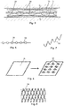
- the side cut of the Fig. 1 shows the structure of a fiber composite part, which is received in a tool 5,6, before the introduction of the resin.
- the tool 5, 6 comprises a lower tool part 5 and an upper tool part 6, which can be moved against the lower tool part 5.
- An insert 20, such as a foam part, is contained in the cavity of the tool 5, 6.
- the cavity also contains one or more fiber layer (s) 10 and between the fiber layer 10 and the insert part 20 there is a layer of a spacer 30, which is designed here as a plurality of spiral fibers, which are preferably evenly distributed over the cavity.
- the insert 20 is optional and can be omitted. In the latter case, the spacers 30 would be in direct contact with the lower tool part 5 or between two fiber layers.
- the state shown is the tool 5, 6 in the partially closed position, in which the inner cavity is larger by a remaining gap 15 than the fiber composite part to be produced.
- the spacers 30 bridge this remaining gap 15, so that there is a distance from the fiber layer 10 to the insert part 20.
- the spacers are preferably already somewhat elastically deformed in order to exert pressure on the fiber layer. After infiltration, they can also deform plastically. If the resin is now injected via an injection point 8, it can spread out in the remaining gap 15. Since the fibers in the fiber layer 10 lie relatively close to one another, the fiber layer 10 represents a relatively high flow resistance It is easier to spread the resin.
- the resin supply is stopped and the tool 5,6 is moved into the completely closed position, which is shown in Fig. 2 is shown.
- the spacers 30 deform elastically. It is also possible for individual or more of the spacers 30 to break in the process. It is also possible for the insert part 20 and / or the fiber layer 10 to deform plastically and / or elastically through contact with the spacers 30 and / or the spacers 30 plastically deform.
- the remaining gap 15 closes.
- the amount of resin injected was dimensioned so that it is sufficient to completely or at least largely penetrate the fiber layer.
- the resin flows from the remaining gap 15 into sections of the fiber layer which have not yet been wetted or soaked.
- the resin is cured via a desired pressure and temperature control.
- the plastic material only has to flow through the fiber layer 10 significantly less than in the prior art, the flow / pressure or force loads on the fiber layer 10 are significantly reduced.
- the problem arose that the fiber layer could shift as a result of the flow and that the structurally provided fiber distribution in the fiber composite part could in some cases not be ensured. This problem has been largely mitigated or solved.
- the shape of the tool can be filled faster. This is a major advantage, especially for large components.
- the mold cavity is preferably evacuated in order to enable the cavity to be filled evenly and completely with resin and, in particular, to avoid air pockets.
- RIFT Resin infusion with flexible tooling
- Fig. 3 shows accordingly a tool with a lower tool shape 5a.
- part 5a can be an insert, such as a foam core, which is to be extrusion-coated and thus becomes part of the fiber composite part.
- a first fiber layer 11 lies on the mold 5a or the foam core 5a, followed by a layer of spacers 30 and a second fiber layer 10 above it.
- a vacuum film 7 lies above this packing.
- the structure described is inside a pressure-tight chamber 3. Via pneumatic devices, not shown The pressure P1 below the vacuum film 7, as well as the pressure P2 outside or above the vacuum film 7 and inside the chamber 3, can be set in a targeted manner.
- the regarding 3 and 4 The spacers 30 described correspond in principle to the spacers described above. It is also advantageous here that a spacing channel or region 15 is spanned by the spacers 30.
- the spacers 30 have a sufficient strength that they can exert a certain pressure on the fiber layer or layers during the filling process in the fiber composite part normal direction, so that the fiber layer (s) do not shift. When an increased pressure is exerted on the spacers, however, they deform so that the distribution channel or region 15 is compressed and, as already described, the resin can be distributed in the fiber layers 10 and / or 11.
- the areas designated P1 and P2 are preferably evacuated.
- the negative pressure P2 can be less than P1, so that the vacuum film is applied to the fiber layer 10 and a slight pressure is exerted on the spacers 30. At this point, the area resulting from the layers 10, 15 and 11 can be injected.
- the resin supply is interrupted and the pressure P2 is increased. For example, a pressure of 6 to 8 bar can be used here. Due to the pressure exerted on the vacuum film 7 and thus on the spacers 30, the spacers 30 deform so that the region 15 is compressed. Resin present there is thus passed into sections of the fiber layers 10 and 11 which have not yet been sufficiently saturated.
- the vacuum film 7 can be removed will. If the part 5a was a lower tool part, this is removed from the finished fiber composite part 1. If part 5a was an insert, this adheres firmly to the fiber layer 11 via the hardened resin and is an integrative part of the fiber composite part 1.
- the layer of the spacers 30 lies between the fiber layers 10 and 11.
- the step of compressing the spacers results in a combined fiber composite layer.
- the fiber layer 10 or 11 can optionally be dispensed with.
- a structure for the production of a sandwich construction is shown, with external fiber-reinforced layers 10 and 11 and a stabilizing core, which results from an insert part 20, such as a foam sheet.
- Spacers 30, which form the distribution channel 15, are provided in each case between the layers 10 and 11 and the insert part.
- the 3 and 4 are also suitable to describe a further alternative embodiment.
- a tool half is located above the vacuum film 7 (not denoted by reference numerals in the figure). This half of the tool limits the maximum position with which the vacuum film 7 can expand upwards. In this way, the maximum cross-section of the composite part is limited.
- this (in 3 and 4 half of the tool (not shown) are already in contact with the vacuum film 7 and, in particular due to their design and position, already cause an elastic deformation of the spacers 30 so that they thereby exert the holding force already explained on the fiber layer (s) 10, 11.
- a uniform component thickness distribution can be achieved or at least supported via the described pressure control of the pressures P1 and P2.
- the use of this upper half of the tool, not shown makes it possible to achieve infiltration pressures, as are known from processes with tools that shape on both sides.
- the top half of the tool does not have to correspond to the manufacturing tolerances and the design of a shaping tool.
- the spacers are not flat or arranged as a layer, but are provided locally and preferably in the recesses 9. This results in an area K2 which has a gap which is free of spacers.
- This gap K2 can be structurally targeted as a resin channel.
- the recesses 9 can also be provided as flow channels for the resin. Especially when the spacers are thin or flat, they offer a low flow resistance, so that a distribution channel K1 is provided due to the recesses 9.
- a pressure is exerted normal to the surface of the fiber composite part, so that the spacers are compressed, so that the finished component in the Fig. 11 shown cross section results.
- a separating film 40 is provided between an upper tool part 6 or spacers 30 and a fiber layer 10, which is symbolized by two parallel lines.
- the separating film 40 can, for example, be a perforated plastic film with holes with a diameter of 0.5-1 mm at intervals of approximately 10 mm.
- the separating film 40 can be a coarsely woven Teflon fabric that has perforation-like openings between the fibers.
- the separating film 40 can also be a tear-off fabric.
- a tear-off fabric is a fabric whose fibers are non-stick coated. If such a layer lies on the outside of a component, it can simply be torn off and its counter-shape becomes apparent on the component surface.
- a component Due to its roughness and structure, such a component is particularly suitable for a subsequent gluing process.
- the resin lying above the separating film 40 is injected and it flows through the openings of the separating film 40 into the fiber layer 10.
- the spacers 30 have the task of fixing both the separating film 40 and the fiber layer 10 locally during the injection process.
- An advantage of this embodiment can be in particular that the spacers are not part of the finished fiber composite part.
- a flat or punctiform spacer can be placed on the component surface or on a tear-off fabric or separating film positioned thereon.
- This can be a semi-finished textile with high permeability.
- These flow aids are often designed as braid, knitted fabric, knitted fabric, partially as a fleece or in some other way.
- Individual objects can be inserted into the gap 15 as a spacer 30. They can be of a compressible foam of sufficient hardness that a pressure against the displacement of the fiber layers 10, 11 is achieved and, at the same time, sufficient flexibility so that they can deform when the pressure increases to close the remaining gap or distribution channel 15.
- the diameter and / or the thickness of the spacers can correspond to the gap thickness.
- the spacers in the gap thickness direction are preferably somewhat larger than the gap, so that the spacers are already elastically compressed during the infiltration and thus exert pressure on the fiber material in order to prevent its displacement.
- the density of the spacers is 1 spacer per 10 cm 2.
- a spacer density in the range of 1 piece per 1 to 80 cm 2 is particularly advantageous.
- a carrier 32 for spacers 35 can be used, which is elongated or flat.
- These objects can be balls, adhesive dots or the like, which protrude radially in relation to the object 32.
- This "protrusion" can be largely uniform all around radially or be oriented in one or more preferred directions so that the spacers resemble the shape of a barbed wire (not shown). As described above, these objects are compressible.
- Fig. 7 shows an embodiment 33 of a spacer in which a wire or a fiber is spiral.
- this can be a plastic or glass fiber, carbon fiber, aramid fiber, ceramic fiber, boron fiber, basalt fiber, natural fiber or nylon fiber. If a fiber that is brittle is used, a breakage of the fiber can be provided for in the design. Adequate rigidity ensures that sufficient pressure is built up on the fiber layer in the tool in the partially closed position.
- These spiral spacers 33 can already be part of the fiber layer 10 or 11. So can For example, up to 10% of the fibers of the fiber layer can be spiral-shaped and the remaining fibers are elongated in order to ensure that the component has a load bearing capacity.
- the fibers that form the spacer lie in particular on the outside of the fiber layer 10, which is directed toward the distribution channel 15.
- FIG. 8 Another alternative is shown which has annular deformations.
- the ring shape increases compared to Fig. 9 the dimensional stability of the resulting spacers 30.
- a part of the film can be punched out centrally in the spacers 30 in order to allow a resin flow from one side to the other side of the film. Punchings can also be provided on the non-deformed base surface of the film for this purpose.
- Fig. 9 The execution of the Fig. 9 is called expanded metal or expanded geometry and is created by arranging a large number of slots in mutually offset rows on a sheet metal or a foil and then stretching transversely to the longitudinal direction of the slot. This results in a three-dimensional structure that can be inserted into the tool gap and thus serves as a spacer. If desired, embossing can increase the spacer heights. The sufficient deformability described is also present here.
- the foam of the insert part 20 can preferably be a defined, lower, fine and / or closed-cell foam with preferably a homogeneous density.
- Polyurethane foams are suitable because they are extremely hard. Also particularly suitable are polyvinyl chloride (PVC) - polypropylene (PP) - polyethylene (PE) -, polyethylene terephthalate (PET) - polybutylene terephthalate (PBT) -, polystylrol (PS) -, expanded polystyrene (EPS) - or cross-linked polystyrene (XPS) - Foams.
- a closed-cell foam is preferably used in order to avoid the foam filling up with the resin, which in addition to the material costs also increases the component weight.
- thermoplastic or a resin can be used as the plastic material.
- An epoxy resin or a vinyl ester-based resin or the like is preferably used as the resin.
- the thickness of the cover layer that is to say the fiber layer 10
- the thickness of the cover layer can be, for example, 2 mm, preference being given to using thickness ranges from 0.2 mm to 20 mm.
- the gap 15 described, through which the resin can flow, that is to say the path difference of the tool between the partially closed and the closed position, is preferably 0.1 to 3 mm, the gap in large components being up to 10 mm.
- a gap thickness of 0.2 to 3 mm is particularly advantageous.
Landscapes
- Engineering & Computer Science (AREA)
- Mechanical Engineering (AREA)
- Chemical & Material Sciences (AREA)
- Composite Materials (AREA)
- Casting Or Compression Moulding Of Plastics Or The Like (AREA)
Description
Die Erfindung betrifft ein Verfahren zur Herstellung von Faserverbundteilen und ein Faserverbundteil.The invention relates to a method for producing fiber composite parts and a fiber composite part.
Bei der Herstellung von Faserverbundbauteilen sollen die Verteilung des Matrixmaterials und die Imprägnierung des trockenen Fasermaterials möglichst schnell erfolgen. Bei Harzinjektionsverfahren in einer geschlossenen Kavität (z. B. beim RTM-Verfahren) kann die Infiltrationsgeschwindigkeit des Matrixmaterials durch eine Erhöhung des Injektionsdruckes gesteigert werden. Insbesondere bei der Herstellung von Bauteilen in Sandwich-Bauweise ist der maximale Injektionsdruck des Matrixmaterials jedoch durch die Werkstoffeigenschaften des Kernmaterials begrenzt. Bei einer zu hohen Einspritzgeschwindigkeit besteht die Gefahr, dass die eingelegten Fasermatten sich verschieben und so zum einen die Tragfähigkeit des Bauteils sinkt und sich eine Verstopfung der Kavität ergeben könnte.When manufacturing fiber composite components, the distribution of the matrix material and the impregnation of the dry fiber material should take place as quickly as possible. In resin injection processes in a closed cavity (e.g. in the RTM process), the infiltration rate of the matrix material can be increased by increasing the injection pressure. However, the maximum injection pressure of the matrix material is limited by the material properties of the core material, in particular in the production of components in sandwich construction. If the injection speed is too high, there is a risk that the inserted fiber mats will shift and, on the one hand, the load-bearing capacity of the component will decrease and the cavity could become blocked.
Um eine weitere Steigerung der Infiltrationsgeschwindigkeit zu erreichen, muss es dem Matrixmaterial ermöglicht werden, sich möglichst ungehindert auszubreiten und das Fasermaterial zu durchtränken. Im Folgenden werden diesbezüglich verschiedene Ansätze vorgestellt. Es ist bekannt, dass sich durch Kanäle im Werkzeug, in dem das Faserverbundbauteil mit Matrixmaterial infiltriert wird, eine möglichst schnelle Verteilung des Matrixmaterials ermöglichen lässt. Das Matrixmaterial kann sich über die Kanäle schnell über die gesamte Bauteiloberfläche verteilen und dringt von diesen Kanälen aus in das Fasermaterial ein. Nachdem das Fasermaterial bereits vollkommen infiltriert ist, verbleibt bei diesem Verfahren Matrixmaterial in den Kanälen, härtet dort aus und verbleibt auf der Bauteiloberfläche. Diese Reinharzgebiete auf der Bauteiloberfläche sind meist unerwünscht. Es gibt verschiedene Möglichkeiten, um diesem unerwünschten Effekt entgegen zu wirken. Im Allgemeinen sehen diese Ansätze temporäre Fließkanäle im Werkzeug vor, welche während des Injektionsvorgangs eine schnelle Verteilung des Matrixmaterials zulassen, danach jedoch kein Verbleib von Matrixmaterial in ihnen ermöglichen. Dieses Vorgehen ist bspw. aus den Schriften
Anstatt im Werkzeug, können, wie aus
Ein weiterer Ansatz, die Durchströmbarkeit des Werkzeugs während des Einspritzvorgangs, (auch Permeabilität) zu erhöhen, sieht vor, das formgebende Werkzeug während der Infiltration nicht komplett zuverschließen. Diese nicht-komplett geschlossene Stellung ist die Stellung, bei der die werkzeuginterne Kavität der Werkstücknegativform noch nicht erreicht ist. Vielmehr ist die Kavität um den nachfolgend beschriebenen Restspalt vergrößert. Diese Verfahren sind als advanced RTM (aRTM) oder Compression-RTM (C-RTM) bekannt. Während der Injektion des Matrixmaterials wird die formgebende Form nicht komplett geschlossen, sodass sich zwischen Fasermaterial und Form ein kleiner Spalt ergibt bzw. das Fasermaterial nicht so sehr kompaktiert wird. Die Kavität ist zu diesem Zeitpunkt jedoch bereits luftdicht verschlossen. Aufgrund des niedrigeren Kampaktierungsgrades bzw. des vorhandenen Spalts ist es dem Matrixmaterial möglich, sich schnell über die Bauteiloberfläche zu verteilen, von wo aus es in das Fasermaterial eindringt. Nachdem ausreichend Matrixmaterial in die Kavität injiziert wurde, wird die Form komplett geschlossen, sodass das Matrixmaterial restlos in das Fasermaterial gedrückt wird. Dieses Verfahren wird bspw. in der Schrift
Bei als aRTM oder C-RTM bekannten Verfahren besteht genauso wie bei den herkömmlichen RTM-Verfahren aufgrund der zunächst gewünscht mäßigen Kompaktierung des Fasermaterials weiter das Risiko, dass sich das Fasermaterial während der Verteilung des Matrixmaterials verschiebt, da das Matrixmaterial teilweise mit hohen Drücken injiziert wird.With processes known as aRTM or C-RTM, just like with conventional RTM processes, due to the initially desired moderate compacting of the fiber material, there is still the risk that the fiber material will shift during the distribution of the matrix material, since the matrix material is partially injected at high pressures .
Eine weitere Möglichkeit, eine schnelle Verteilung des Matrixmaterials zu realisieren, besteht darin, eine flächige Fließhilfe vorzusehen. Eine solche Fließhilfe ist ein textiles Halbzeug mit hoher Permeabilität. Häufig werden diese Fließhilfen als Geflecht, Gewirk, Gestrick, teilweise als Vlies oder andersartig ausgeführt. Solche flächigen Fließhilfen sind besonders aus dem Bereich der Harzinfusionsprozesse mit einseitig formgebendem Werkzeug (Resin Infusion unter Flexible Tooling, RIFT) bekannt.Another possibility of realizing a rapid distribution of the matrix material is to provide a flat flow aid. Such a flow aid is a semi-finished textile with high permeability. These flow aids are often designed as braid, knitted fabric, knitted fabric, partially as a fleece or in some other way. Such flat flow aids are particularly known from the area of resin infusion processes with one-sided shaping tool (resin infusion under flexible tooling, RIFT).
Dokument
Dokument
Dokument
Es ist die Aufgabe der Erfindung ein verbessertes Verfahren der Füllung von Gussformen, insbesondere nach dem RTM-Verfahren bereitzustellen, bei dem bei einer hohen Füllgeschwindigkeit ein schädliches Verschieben von vorhandenen Fasern oder Matten oder dergleichen nicht stattfindet.It is the object of the invention to provide an improved method of filling molds, in particular according to the RTM method, in which there is no harmful displacement of existing fibers or mats or the like at a high filling speed.
Diese Aufgabe wird mit dem Verfahren des Anspruchs 1 und einer Kombination aus einer Faserschicht und einem oder einer Mehrzahl von Abstandhaltern zur Herstellung eines entsprechenden Faserverbundteils gelöst. Vorteilhafte Ausführungsformen ergeben sich aus den abhängigen Ansprüchen.This object is achieved with the method of claim 1 and a combination of a fiber layer and one or a plurality of spacers for producing a corresponding fiber composite part. Advantageous embodiments result from the dependent claims.
Bei einem Verfahren zur Herstellung eines Faserverbundteils werden zumindest eine Faserschicht und ein Abstandshalter oder eine Mehrzahl von Abstandhaltern in eine Kavität einer Form eingebracht, so dass sich durch die Abstandhalter insbesondere benachbart zur Faserschicht zumindest ein Verteilkanal oder -bereich für das einzuspritzende Kunststoffmaterial ergibt, und das Kunststoffmaterial wird in die Form eingespritzt. Nachfolgend wird die Kavität der Form auf das Faserverbundteilmaß gebracht, wobei der oder die Abstandhalter sich verformen und in dem Verteilkanal oder -bereich enthaltenes Kunststoffmaterial in die Faserschicht fließt. Dadurch wird erreicht, dass sich das Kunststoffmaterial bestmöglich, also unter geringen Fließwiderstand in der Form verteilen kann. Es wird kein gesonderter Arbeitsschritt benötigt, um die Abstandhalter aus der Form herauszuholen. Dabei fallen bspw. die aus dem Stand der Technik bekannten Schieber zur Bereitstellung eines temporären Verteilkanals weg. Der Verteilkanal hat in der Summe mit den Abstandhaltern bevorzugt eine Dichte, die bis zu 30% der Dichte der Faserschicht vor dem Füllen der Faserschicht mit Kunststoff ausmacht. Das genannte Verformen der Abstandhalter kann auch ein Brechen der Abstandhalter umfassen. Insbesondere können die Abstandhalter Sollbruchstellen aufweisen, die durch eine entsprechende Belastung brechen. Zeitlich vor dem Einspritzen des Kunststoffmaterials und/oder während dem Einspritzen des Kunststoffmaterials in die Kavität der Form entspricht die Kavität insbesondere nicht dem Endmaß des herzustellenden Faserverbundteils.. Bevorzugt ist das Kunststoffmaterial ein aushärtbares Harz. Alternativ kann auch ein anderer Kunststoff, wie z.B. ein Elastomer verarbeitet werden.In a method for producing a fiber composite part, at least one fiber layer and a spacer or a plurality of spacers are introduced into a cavity of a mold, so that the spacers, in particular adjacent to the fiber layer, result in at least one distribution channel or region for the plastic material to be injected, and that Plastic material is injected into the mold. The cavity of the mold is subsequently brought to the partial fiber composite dimension, the spacer or spacers deforming and plastic material contained in the distribution channel or region flowing into the fiber layer. This ensures that the plastic material can be distributed in the mold in the best possible way, i.e. with low flow resistance. No separate work step is required to get the spacers out of the mold. For example, the slides known from the prior art for providing a temporary distribution channel are omitted. The total distribution channel with the spacers preferably has a density that makes up up to 30% of the density of the fiber layer before the fiber layer is filled with plastic. Said deformation of the spacers can also include breaking of the spacers. In particular, the spacers can have predetermined breaking points, which are characterized by a corresponding Break load. In time before the injection of the plastic material and / or during the injection of the plastic material into the cavity of the mold, the cavity in particular does not correspond to the final dimension of the fiber composite part to be produced. The plastic material is preferably a curable resin. Alternatively, another plastic, such as an elastomer, can be processed.
Insbesondere weist die Form ein mehrere gegeneinander verfahrbare Teile umfassendes Werkzeug auf und die Form befindet sich während des Einspritzens des Harzes in die Kavität in einem teilgeschlossenen Zustand, bei dem es bereits bis auf einen geringen Restspalt geschlossen ist und die Form verfährt nach dem Beenden des Einspritzens in die geschlossene Stellung, bei der insbesondere die Werkzeugkavität dem herzustellenden Faserverbundteils entspricht. Die Verfahrbewegung kann durch einen automatischen Antrieb oder manuell erfolgen. Auf die beschriebene Art kann man ein bereits vorhandenes Werkzeug, bzw. eine entsprechende Form für das erfindungsgemäße Verfahren nutzen.In particular, the mold has a tool comprising a plurality of parts which can be moved relative to one another and the mold is in a partially closed state during the injection of the resin into the cavity, in which it is already closed to a small residual gap and the mold moves after the injection has ended in the closed position, in which in particular the tool cavity corresponds to the fiber composite part to be produced. The movement can be done by an automatic drive or manually. In the manner described, an existing tool or a corresponding shape can be used for the method according to the invention.
Bevorzugt wird bei einem RIFT-Verfahren eine formgebende Struktur vorgesehen, die ein Teil der Form oder Teil eines Einlageteils ist und in einem Spalt zwischen der formgebenden Struktur und einer Vakuumfolie sind eine Faserschicht und ein Abstandshalter oder eine Mehrzahl an Faserschichten oder der Abstandhalter angeordnet. Kunststoffmaterial wird in den Spalt eingespritzt und nachfolgend verformen, insbesondere komprimieren, sich über einen relativen Überdruck von dem Umgebungsdruck zu dem im Spalt herrschenden Druck die Abstandhalter. Auch so kann eine gleichmäßige Harzverteilung in der Form bewirkt werden.In a RIFT method, a shaping structure is preferably provided, which is part of the shape or part of an insert part, and a fiber layer and a spacer or a plurality of fiber layers or the spacer are arranged in a gap between the shaping structure and a vacuum film. Plastic material is injected into the gap and subsequently deform, in particular compress, the spacers over a relative overpressure from the ambient pressure to the pressure prevailing in the gap. Even this way, a uniform resin distribution in the mold can be achieved.
Es kann insbesondere zwischen den Abstandhaltern und der Faserschicht eine Trennschicht verwendet. So kann erreicht werden, dass die Abstandhalter nicht Teil des fertigen Faserverbundbauteils sind. Faserverbundbauteile sind gerade im Flugzeugbereich festigkeitsoptimierte Komponenten, was bedeutet, dass integrierte Abstandhalter nicht kalkulierte oder nicht kalkulierbare Einflüsse bewirken könnten.In particular, a separating layer can be used between the spacers and the fiber layer. It can thus be achieved that the spacers are not part of the finished fiber composite component. Composite components are strength-optimized components, especially in the aircraft sector, which means that integrated spacers could cause incalculated or incalculable influences.
Insbesondere sind die Abstandshalter Teil einer flächigen Struktur, wie insbesondere einem Blatt oder einer Folie oder einem anderen flächigen Halbzeug, die dreidimensional derart verformt, geprägt, gestanzt, tiefgezogen und/oder geschnitten ist, so dass die Abstandshalter gegenüber einer Hauptebene der flächigen Struktur vortreten. Neben vielen anderen Ausführungsarten kann bspw. eine wellenartige Gestalt vorteilhaft sein. Die Ausführung als flächige Struktur macht es einfach die Abstandhalter zu positionieren. Es muss nämlich lediglich die Folie in das Werkzeug eingelegt werden. Bei der Harzinfusion auf einseitig formgebendem Werkzeug wird häufig eine flächige Fließhilfe auf die Bauteiloberfläche bzw. auf ein auf dieser positioniertem Abreißgewebe gelegt. Ein solcher Abstandhalter ist bevorzugt ein textiles Halbzeug mit hoher Permeabilität. Häufig werden diese Abstandhalter als Geflecht, Gewirk, Gestrick, teilweise als Vlies oder andersartig ausgeführt. Der Abstandhalter kann als eine Art Rost oder Gitter oder auch ein steifes Gewebe bzw. Gewirke oder Geflecht, welches sich nicht unter Vakuum stark kompaktieren lässt und z. B. aus den Werkstoffen Metall, Kunststoffen oder textilen Halbzeugen ausgeführt sein. Als Abstandhalter können Prepregs, also mit Kunststoffmaterial versehene Fasern, sein, die eine ausreichende Biegesteifigkeit aufweisen. Auch können mit einem Binder, wie z.B. einem Thermoplasten, versehene Fasern verwendet werden.In particular, the spacers are part of a flat structure, such as in particular a sheet or a film or another flat semifinished product, which is three-dimensionally deformed, embossed, punched, deep-drawn and / or cut so that the spacers protrude from a main plane of the flat structure. In addition to many other embodiments, a wave-like shape can be advantageous, for example. The design as a flat structure makes it easy to position the spacers. All you have to do is insert the film into the tool. In the case of resin infusion on one-sided shaping tool, a flat flow aid is often placed on the component surface or on a tear-off fabric positioned on it. Such a spacer is preferably a semi-finished textile with high permeability. These spacers are often designed as braid, knitted fabric, knitted fabric, partially as a fleece or in some other way. The spacer can be a type of grate or grid or a rigid fabric or knitted fabric or braid, which can not be compacted strongly under vacuum and z. B. from the materials metal, plastics or textile semi-finished products. Prepregs, that is to say fibers provided with plastic material, which have sufficient flexural rigidity can be used as spacers. Also with a binder, e.g. a thermoplastic, provided fibers are used.
Alternativ oder zusätzlich können ein oder mehrere längliche Objekte, wie insbesondere Fäden, Fasern, Drähte,.. etc., in das Werkzeug eingebracht werden, wobei diese Objekte entweder radial vorstehende Bereiche aufweisen, die als Abstandshalter dienen. Oder diese Objekte können auch eine Verzwirbelung oder eine Verdrehung oder eine Spiralform aufweisen, so dass diese Objekte selbst als Abstandshalter dienen. Diese länglichen Objekte können gitterartig vernetzt sein. Einzelne Fasern können technisch einfach mit derartigen Verdickungen oder Verformungen versehen werden, so dass der Abstandhalter als ein kostengünstig herstellbares Halbzeug in das Werkzeug eingelegt wird. Durch die Längserstreckung der länglichen Objekte werden die Abstandhalter unmittelbar in den benötigten Abstand zueinander ausgerichtet. An den länglichen Objekten können radial lokal bzw. einseitig oder radial umlaufend Vorsprünge sein, so dass sich in etwa das Erscheinungsbild eines Stacheldrahts oder einer Perlenschnur ergibt.Alternatively or additionally, one or more elongated objects, such as in particular threads, fibers, wires, etc., can be introduced into the tool, these objects either having radially projecting regions which serve as spacers. Or these objects can also have a swirl or a twist or a spiral shape, so that these objects themselves serve as spacers. These elongated objects can be lattice-like to be connected. Individual fibers can be provided with such thickening or deformations in a technically simple manner, so that the spacer is inserted into the tool as a semi-finished product which can be produced inexpensively. Due to the longitudinal extension of the elongated objects, the spacers are directly aligned in the required distance from each other. On the elongated objects there can be projections radially locally or on one side or radially circumferentially, so that there is approximately the appearance of a barbed wire or a string of pearls.
Bei einem entsprechenden Verfahren werden insbesondere eine Mehrzahl einzelner Abstandselemente in das Werkzeug eingebracht und diese Abstandselemente sind entweder einzelne Körper, die eingelegt und/oder verklebt werden oder die Abstandshalter werden vor dem Einbringen der Faserschicht in das Werkzeug mit der Faserschicht verbunden. Hiermit wird nicht abschließend eine Anzahl unterschiedlicher Methoden der Herstellung beschrieben. Für spiralförmige Abstandhalter kann insbesondere der Begriff "spiralförmig" derart definiert sein, dass in einem elastisch nicht verspannten Zustand des Abstandhalters eine radiale Auslenkung besteht, die mehr als dem 5-fachen, bevorzugt dem 10-fachen seines Durchmessers entspricht und insbesondere besteht diese radiale Auslenkung in beiden zueinander senkrecht stehenden Radialrichtungen.In a corresponding method, in particular a plurality of individual spacer elements are introduced into the tool and these spacer elements are either individual bodies which are inserted and / or glued or the spacers are connected to the fiber layer before the fiber layer is introduced into the tool. It does not conclusively describe a number of different methods of manufacture. For spiral spacers, the term "spiral" can in particular be defined in such a way that in an elastically non-tensioned state of the spacer there is a radial deflection which corresponds to more than 5 times, preferably 10 times its diameter and in particular this radial deflection exists in both mutually perpendicular radial directions.
Insbesondere werden eine Mehrzahl einzelner Abstandhalter in den Verteilkanal oder -bereich eingebracht und diese Abstandhalter sind entweder einzelne oder getrennte Körper, die in die Form eingelegt werden und/oder sie werden an der im Werkzeug eingebrachten Faserschicht oder einer anderen Schicht angeklebt oder die Abstandshalter werden vor dem Einbringen in die Form mit der Faserschicht oder einer anderen Schicht oder einem Einlegeteil verbunden.In particular, a plurality of individual spacers are introduced into the distribution channel or region and these spacers are either individual or separate bodies which are inserted into the mold and / or they are glued to the fiber layer or another layer introduced into the tool or the spacers are in front the introduction into the mold with the fiber layer or another layer or an insert.
Bevorzugt werden pro 80 cm2 der Verbundteiloberfläche zumindest ein Abstandshalter verwendet. Gerade wenn das die Abstandhalter umfassende Teil (wie z.B. eine Folie) so geformt ist, dass entweder eine weitgehend flächige Kontaktfläche zu der Faserschicht besteht oder ein Linienkontakt von dem Abstandhalter zu der Faserschicht besteht, kann diese Abstandhalterdichte ausreichen. Diese Abstandhalterdichte kann auch bei punktförmigen Kontakten von den Abstandhaltern zu der Faserschicht und/oder zu der Verbundteiloberfläche zum Einsatz kommen. Gerade wenn die Abstandhalter punktförmige Kontakte zu der Verbundteiloberfläche haben, kann eine größere Abstandhalterdichte vorteilhaft sein. So können mindestens 1 Abstandhalter pro cm2 von der Abstandsoberfläche zu der Faserschicht bestehen, um so effektiv ein Verschieben des Fasermaterials zu verhindern.At least one spacer is preferably used per 80 cm 2 of the composite part surface. Especially if that's the spacer comprehensive part (such as a film) is shaped so that either there is a largely flat contact surface with the fiber layer or there is line contact from the spacer to the fiber layer, this spacer density can be sufficient. This spacer density can also be used in the case of punctiform contacts from the spacers to the fiber layer and / or to the composite part surface. If the spacers have point-like contacts to the surface of the composite part, a greater spacer density can be advantageous. So there can be at least 1 spacer per cm 2 from the spacer surface to the fiber layer so as to effectively prevent the fiber material from shifting.
Ein Faserverbundbauteil umfasst eine Faserschicht eines faserverstärkten Materials. Dabei hat die Faserschicht abzüglich des Harzes eine erste Dichte. Zumindest zu einer Seite der Faserschicht sind Abstandhalter angeordnet, die sich in einer elastischen Verspannung befinden. Die Abstandhalter würden nach einem Entfernen des Harzes und Lösen der elastischen Verspannung eine Schicht oder Bereiche bilden, die eine zweite Dichte aufweist und die zweite Dichte beträgt höchstens 25% der ersten Dichte. Wenn beispielsweise die Abstandhalter spiralförmig geformte Fasern sind, so lassen sich diese Fasern aus dem Harz herauslösen und so erkennen, wie ihre (elastisch) unverformte Geometrie ist. Hieraus lässt sich die Dicke dieser Schicht bestimmen und somit die genannten Dichteverhältnisse, die jeweils ohne den Harzanteil bestimmt werden. Die Schicht der reduzierten Dichte muss nicht durchgehend ausgebildet sein, sondern es können lediglich entsprechende Bereiche oder Zonen lokal ausgebildet sein. Wenn lokale Bereiche der Abstandhalter bestehen, so wird bei der Bestimmung der genannten Dichte die über die Abstandhalter aufgespannte Fläche betrachtet. Wenn in einem z.B. thermischen oder chemischen Verfahren das Harz entfernt wird so ist die ursprüngliche Form der Abstandhalter wieder erkennbar und erkennbar, ob das erfindungsgemäße Verfahren genutzt wurde. Auch kann erkennbar sein, wenn eine plastische Verformung von den Abstandhaltern vorliegt. Dies gilt insbesondere, wenn die Abstandhalter aus einem Schaum gefertigt sind und bei einem Röntgenverfahren gesehen wird, dass die einzelnen Zellen des Schaums verformt und dabei insbesondere quer zur Bauteiloberfläche komprimiert sind. Wenn eine Kompression der Abstandhalter von zumindest 40% in Faserverbundteilquerrichtung vorliegt, werden bevorzugt die erfindungsgemäßen Vorteile erreicht.A fiber composite component comprises a fiber layer of a fiber-reinforced material. The fiber layer minus the resin has a first density. Spacers are located at least on one side of the fiber layer, which are in an elastic bracing. After the resin has been removed and the elastic bracing has been released, the spacers would form a layer or regions which have a second density and the second density is at most 25% of the first density. If, for example, the spacers are spirally shaped fibers, these fibers can be detached from the resin and can be seen how their (elastic) undeformed geometry is. From this, the thickness of this layer can be determined and thus the mentioned density ratios, which are determined without the resin content. The layer of reduced density does not have to be formed continuously, but only corresponding areas or zones can be formed locally. If there are local areas of the spacers, the area spanned by the spacers is considered when determining the density mentioned. If the resin is removed in a thermal or chemical process, for example, the original shape of the spacers can be recognized again and whether the process according to the invention has been used. It can also be seen if a plastic deformation of the Spacers are present. This applies in particular if the spacers are made of a foam and it is seen in an X-ray process that the individual cells of the foam are deformed and are compressed in particular transversely to the component surface. If the spacers are compressed by at least 40% in the transverse direction of the fiber composite part, the advantages according to the invention are preferably achieved.
Im Folgenden werden bevorzugte Ausführungsbeispiele der Erfindung anhand von schematischen Darstellungen näher erläutert. Es zeigen:
- Fig. 1
- eine schematische Ansicht eines zweiteiligen Werkzeugs in der teilgeschlossenen Stellung zum Zeitpunkt vor oder während des Einspritzen des Kunststoffs,
- Fig. 2
- das Werkzeug gemäß
Fig. 1 in der geschlossenen Stellung, bei dem die Werkzeugkavität der Geometrie des fertigen Faserverbundteils entspricht, - Fig. 3
- ein Halbschalenwerkzeug (RIFT) im Zustand vor oder während dem Einspritzen des Harzes,
- Fig. 4
- das Werkzeug gemäß
Fig. 3 im Zustand, dass das Harz eingespritzt ist und das Faserverbundteil hergestellt wurde, - Fig. 5
- eine schematische Ansicht des Aufbaus einer Sandwichkonstruktion vor dem Einspritzen des Harzes,
- Fig. 6
- eine schematische Ansicht eines länglichen Abstandshalters mit lokalen kompressiblen Verdickungen,
- Fig. 7
- eine schematische Ansicht eines spiralförmigen Abstandshalters,
- Fig. 8
- zwei Ansichten zur Erläuterung der Herstellung eines Trägers von Abstandshaltern in einer alternativen Ausführungsform,
- Fig. 9
- ein Abstandhalter aus einem Streckmetall,
- Fig. 10
- eine Ansicht einer Geometrie eines Faserverbundteils mit Bereichen zur Aufnahme der Abstandhalter im Zustand vor oder während dem Einspritzvorgang,
- Fig. 11
- das Faserverbundteil gemäß
Fig. 10 in seiner Endgeometrie nach Verbringen des Werkzeugs in die geschlossene Stellung - Fig. 12
- eine Ansicht eines alternativen Herstellungsverfahrens mit einer Trennfolie und
- Fig. 13
- das Herstellverfahren gemäß
Fig. 12 , bei dem das Werkzeug in seiner geschlossenen Stellung ist.
- Fig. 1
- 2 shows a schematic view of a two-part tool in the partially closed position at the time before or during the injection of the plastic,
- Fig. 2
- the tool according to
Fig. 1 in the closed position, in which the tool cavity corresponds to the geometry of the finished fiber composite part, - Fig. 3
- a half-shell mold (RIFT) in the state before or during the injection of the resin,
- Fig. 4
- the tool according to
Fig. 3 in the state that the resin is injected and the fiber composite part has been produced, - Fig. 5
- 1 shows a schematic view of the structure of a sandwich construction before the resin is injected,
- Fig. 6
- 1 shows a schematic view of an elongated spacer with local compressible thickenings,
- Fig. 7
- 1 shows a schematic view of a spiral spacer,
- Fig. 8
- two views to explain the manufacture of a spacer support in an alternative embodiment,
- Fig. 9
- a spacer made of expanded metal,
- Fig. 10
- 2 shows a view of a geometry of a fiber composite part with areas for receiving the spacers in the state before or during the injection process,
- Fig. 11
- the fiber composite part according
Fig. 10 in its final geometry after moving the tool into the closed position - Fig. 12
- a view of an alternative manufacturing method with a release film and
- Fig. 13
- the manufacturing process according to
Fig. 12 with the tool in its closed position.
Der seitliche Schnitt der
In dem in
Da im beschriebenen Verfahren das Kunststoffmaterial im Vergleich zum Stand der Technik nur deutlich weniger die Faserschicht 10 durchströmen muss, sind die Strömungs- /Druck- bzw. Kraftbelastungen auf die Faserschicht 10 deutlich reduziert. Bei herkömmlich bekannten Ausführungsformen trat das Problem auf, dass die Faserschicht durch das Durchströmen sich verschieben konnte und die konstruktiv vorgesehene Faserverteilung im Faserverbundteil teilweise nicht sichergestellt werden konnte. Dieses Problem wurde weitgehend entschärft bzw. gelöst. Zudem kann die Form des Werkzeugs schneller gefüllt werden. Dies ist gerade bei großen Bauteilen ein wesentlicher Vorteil.Since in the described method the plastic material only has to flow through the
Auch musste bei den bestehenden Infusions- bzw. Infiltrationsverfahren mit hohen Drücken gearbeitet werden, die teilweise größer als 25 bar waren, um so die Faserschicht in angemessener Zeit durchdringen zu können. Durch die beschriebene Vergrößerung des Strömungsquerschnitts innerhalb des Restspalts ist es möglich, die Drücke wesentlich zu senken, auf Bereiche von 2 bis 3 bar oder bis bspw. 5 bar.The existing infusion and infiltration processes also had to work with high pressures, some of which were greater than 25 bar, in order to be able to penetrate the fiber layer in a reasonable time. The described enlargement of the flow cross section within the remaining gap makes it possible to reduce the pressures considerably, to ranges from 2 to 3 bar or up to, for example, 5 bar.
Bereits in dem Zustand, dass das Werkzeug in der teilgeschlossenen Stellung ist, ist es bevorzugt hermetisch geschlossen. Vor dem Einspritzen des Harzes wird die Werkzeugkavität bevorzugt evakuiert, um ein gleichmäßiges und komplettes Füllen der Kavität mit Harz zu ermöglichen und insbesondere Lufteinschlüsse zu vermeiden.Already in the state that the tool is in the partially closed position, it is preferably hermetically closed. Before the resin is injected, the mold cavity is preferably evacuated in order to enable the cavity to be filled evenly and completely with resin and, in particular, to avoid air pockets.
Die Verwendung von Abstandhaltern 30 bei dem Einspritzvorgang ist auch bei dem RIFT-Verfahren (RIFT= Resin infusion with flexible tooling) möglich, wie dies mit den
Die in Bezug auf
Vor der Befüllung der Kavität zwischen der Vakuumfolie 7 und dem Werkzeugunterteil 5a mit Harz werden in bevorzugter Weise die mit P1 und P2 bezeichneten Bereiche evakuiert. Dabei kann der Unterdruck P2 weniger stark sein als P1, so dass die Vakuumfolie sich an die Faserschicht 10 anlegt und ein leichter Druck auf die Abstandhalter 30 ausgeübt wird. Zu diesem Zeitpunkt kann in den Bereich, der sich aus den Schichten 10, 15 und 11 ergibt, eingespritzt werden. Nach der ausreichenden Harzfüllung wird die Harzzufuhr unterbrochen und der Druck P2 wird erhöht. Hier kann beispielsweise ein Druck von 6 bis 8 bar verwendet werden. Durch den auf die Vakuumfolie 7 und somit auf die Abstandhalter 30 bewirkten Druck verformen sich die Abstandhalter 30, so dass der Bereich 15 zusammengedrückt wird. Dort vorhandenes Harz wird so in Abschnitte der Faserschichten 10 und 11 geleitet, die noch nicht ausreichend durchtränkt waren. Nach dem Aushärten des Harzes kann die Vakuumfolie 7 entfernt werden. Sofern das Teil 5a ein Werkzeugunterteil war, wird dieses von dem fertigen Faserverbundteil 1 entfernt. Sofern das Teil 5a ein Einlegeteil war, so haftet dies fest über das ausgehärtete Harz an der Faserschicht 11 und ist integratives Teil des Faserverbundteils 1.Before the cavity between the
Gemäß
Die
In
Als Abstandhalter 30 können einzelne Objekte in den Spalt 15 eingelegt sein. Sie können aus einem kompressiblen Schaum ausreichender Härte sein, dass ein Druck gegen das Verschieben der Faserschichten 10, 11 erreicht wird und gleichzeitig ausreichender Flexibilität, so dass sie sich bei einer Druckerhöhung zum Schließen des Restspalts bzw. Verteilkanals 15 verformen können. Die Durchmesser und/oder die Dicke der Abstandhalter kann der Spaltdicke entsprechen. Bevorzugt sind die Abstandhalter in Spaltdickenrichtung etwas größer als der Spalt, so dass die Abstandhalter während der Infiltration schon elastisch zusammengedrückt sind und so einen Druck auf das Fasermaterial ausüben, um dessen Verschieben zu verhindern. Die Dichte der Abstandhalter beträgt bei der beschriebenen Ausführungsform 1 Abstandhalter pro 10 cm2. Vorteilhaft ist insbesondere eine Abstandhalterdichte im Bereich von 1 Stück pro 1 bis 80 cm2.Individual objects can be inserted into the
Auch kann gemäß
In
Die Ausführung der
Der Schaum des Einlageteils 20 kann bevorzugt ein definierter, niedriger, fein- und/oder geschlossenzelliger Schaum mit bevorzugt einer homogenen Dichte. Es eignen sich Polyurethanschäume, da sie eine hohe Härte aufweisen. Ferner eignen sich insbesondere Polyvinylchlorid (PVC)- Polypropylen(PP)- Polyethylen(PE)-, Polyethylenterephtalat (PET)- Polybutylenterephtalat (PBT)-, Polystylrol (PS)-, expandierte Polystyrol (EPS)- oder vernetzte Polystryrol (XPS)-Schäume. Bevorzugt wird ein geschlossenzelliger Schaum verwendet, um zu vermeiden, dass der Schaum sich mit dem Harz füllt, was neben den Materialkosten auch das Bauteilgewicht erhöht.The foam of the
Als Kunststoffmaterial kann ein Thermoplast oder ein Harz verwendet werden. Als Harz kommt bevorzugt ein Epoxidharz oder ein Harz auf Vinylesterbasis oder dergleichen zum Einsatz.A thermoplastic or a resin can be used as the plastic material. An epoxy resin or a vinyl ester-based resin or the like is preferably used as the resin.
Die Dicke der Decklage, also der Faserschicht 10, kann bspw. 2 mm betragen, wobei bevorzugt Dickenbereiche von 0,2 mm bis 20 mm verwendet werden können. Der beschriebene Spalt 15, durch den das Harz einfließen kann, also die Wegdifferenz des Werkzeugs zwischen der teilgeschlossenen und der geschlossenen Stellung, beträgt bevorzugt 0,1 bis 3 mm, wobei bei großen Bauteilen der Spalt bis zu 10 mm betragen kann. Insbesondere ist eine Spaltdicke von 0,2 bis 3 mm vorteilhaft.The thickness of the cover layer, that is to say the
- 11
- FaserverbundteilFiber composite part
- 33rd
- Kammerchamber
- 55
- WerkzeugunterteilLower part of the tool
- 5a5a
- Einlageteil oder WerkzeugunterteilInsert part or tool lower part
- 66
- WerkzeugoberteilUpper part of the tool
- 77
- VakuumfolieVacuum film
- 88th
- EinspritzpunktInjection point
- 99
- AusnehmungenRecesses
- 1010th
- FaserschichtFiber layer
- 1111
- FaserschichtFiber layer
- 1515
- Restspalt, VerteilkanalResidual gap, distribution channel
- 2020th
- Einlageteil, z.B. SchaumstoffkörperInsert part, e.g. Foam body
- 3030th
- AbstandhalterSpacers
- 3131
- Foliefoil
- 3232
- längliches Objekt, Faser, Faden, etc.elongated object, fiber, thread, etc.
- 3333
- Spiralespiral
- 3434
- gitterförmiges Objektlattice-shaped object
- 3535
- Kugel, Klebepunkt, etc.Ball, glue point, etc.
- 4040
- Trennschicht, TrennfolieSeparating layer, separating film
- K1, K2K1, K2
- FließkanäleFlow channels
Claims (9)
- Method for producing a fibre composite part (1), wherein at least one fibre layer (10, 11) and a spacer (30, 33-35) or a plurality of spacers (30, 33-35) are introduced into a cavity of a mould (5, 6, 7), such that the spacers (30, 33-35) provide, in particular adjacent to the fibre layer (10), at least one distributing channel or region (15) for the plastics material to be injected, and the plastics material is injected into the mould (5, 6, 7), and subsequently the cavity of the mould is brought to the dimensions of the fibre composite part, wherein the spacer or spacers (30, 33-35) deform(s) and/or break(s) and plastics material contained in the distributing channel or region (15) flows into the fibre layer (10, 11),
wherein one or more elongate objects (32) in the form of threads, fibres or wires are introduced into the mould (5, 5a, 6, 7), wherein these objects (32) either have radially projecting regions which serve as spacers (30) or wherein these objects have a twisting or a turning or a spiral shape, such that these objects serve as spacers (30). - Method according to Claim 1, wherein the mould (5, 6) has a die comprising a plurality of parts that can be moved with respect to one another and, during the injection of the plastics material into the cavity, the mould (5, 6) is in a partially closed state, in which it is closed except for a small residual gap, and, after the injection has ended, the mould (5, 6) moves into the closed position, in which in particular the die cavity corresponds to the fibre composite part (1) to be produced.
- Method according to Claim 1, wherein provided on one side of the fibre layer (10) is a shaping structure (5a), which is a part of the mould or part of an insert part (5a), and the fibre layer (10, 11) and the spacer or the plurality of spacers (30, 33-35) are arranged in a gap (15) between the shaping structure and a vacuum film (7), and plastics material is injected into the gap (15) and subsequently the spacers (30) are deformed, in particular compressed, by way of a relative excess pressure of the ambient pressure (P2) in relation to the pressure (P1) prevailing in the gap, and thus in particular the plastics material is made to flow to distribute the plastic uniformly.
- Method according to Claim 3, characterized in that a separating layer (40) is used between the spacers and the fibre layer (10).
- Method according to one of the preceding claims, characterized in that the spacers (30) are part of a planar structure, such as in particular a sheet or a film (31), which is three-dimensionally deformed, embossed, punched, deep-drawn and/or cut in such a way that the spacers (30) protrude with respect to a main plane of the planar structure (31) .
- Method according to one of the preceding claims, characterized in that the at least one spacer (30) is of a spiral form, wherein in particular a spiral form is defined such that, over an axial length of the spacer of 3 cm in an elastically non-braced state, the spacer has a radial deflection which corresponds to more than 5 times, preferably 10 times, its diameter and in particular this radial deflection exists in the two radial orientations perpendicular to one another.
- Method according to one of the preceding claims, characterized in that a plurality of individual spacers (30) are introduced into the distributing channel or region (15) and these spacers (30) are either individual or separate bodies, which are placed into the mould and/or adhesively bonded to the fibre layer (10) introduced into the die or to another layer,
or
before being introduced into the mould, the spacers (30) are bonded to the fibre layer (10) or to another layer or insert part (5a) or to this part. - Method according to one of the preceding claims, characterized in that at least one spacer (30, 33-35) is used per 80 cm2 of the fibre composite part (1) and in particular at least one spacer (30, 33-35) is used per 10 cm2 of the fibre composite part (1) .
- Combination of a fibre layer (10) of a fibre-reinforced material and one or a plurality of spacers (30) for producing a fibre composite component (1), characterized in that the fibre layer (10), less a plastics material to be injected, has a first density and arranged at least on one side of the fibre layer (10) are the one or the plurality of spacers (30) which are either elastically braced, wherein, after removing the plastics material and releasing the elastic bracing, the spacers would form a layer or regions which have a second density and the second density is at most 25% of the first density, or the spacers (30) are discernibly in a deformed state compared to an undeformed state, wherein at least a compression of the spacers (30) of 40% is in the transverse direction of the fibre composite part, wherein the spacers (30) comprise one or more elongate objects (32) in the form of threads, fibres or wires, wherein these objects (32) either have radially projecting regions which serve as spacers (30) or wherein these objects have a twisting or a turning or a spiral shape, such that these objects serve as spacers (30).
Applications Claiming Priority (1)
| Application Number | Priority Date | Filing Date | Title |
|---|---|---|---|
| DE102014017200.7A DE102014017200A1 (en) | 2014-11-21 | 2014-11-21 | Process for the production of fiber composite parts and a fiber composite part |
Publications (2)
| Publication Number | Publication Date |
|---|---|
| EP3023236A1 EP3023236A1 (en) | 2016-05-25 |
| EP3023236B1 true EP3023236B1 (en) | 2020-06-03 |
Family
ID=54703778
Family Applications (1)
| Application Number | Title | Priority Date | Filing Date |
|---|---|---|---|
| EP15195422.9A Active EP3023236B1 (en) | 2014-11-21 | 2015-11-19 | Method for manufacturing fibre composites and pre-product |
Country Status (2)
| Country | Link |
|---|---|
| EP (1) | EP3023236B1 (en) |
| DE (1) | DE102014017200A1 (en) |
Families Citing this family (6)
| Publication number | Priority date | Publication date | Assignee | Title |
|---|---|---|---|---|
| CN108188259B (en) * | 2017-12-30 | 2023-11-10 | 连云港神鹰碳纤维自行车有限公司 | Forming die and forming method for mounting hole for preventing yarn clamping |
| JP7114266B2 (en) | 2018-02-13 | 2022-08-08 | 三菱重工業株式会社 | Composite material manufacturing method and fiber base material |
| FR3083735B1 (en) * | 2018-07-10 | 2020-09-11 | Safran Nacelles | METHOD OF MANUFACTURING A COMPOSITE PANEL |
| WO2020038584A1 (en) * | 2018-08-23 | 2020-02-27 | Rhodia Operations | Composites with flow enhancing structures and process for their manufacture |
| FR3105075B1 (en) * | 2019-12-19 | 2022-02-11 | Stelia Aerospace | Draining molding device for a system for manufacturing composite material parts |
| CN115122720B (en) * | 2022-06-28 | 2023-03-10 | 北京航空航天大学 | Fiber reinforced metal laminate and method of forming the same |
Family Cites Families (11)
| Publication number | Priority date | Publication date | Assignee | Title |
|---|---|---|---|---|
| US6406659B1 (en) | 1995-03-28 | 2002-06-18 | Eric Lang | Composite molding method and apparatus |
| NL1007152C2 (en) * | 1997-09-29 | 1999-03-31 | Dsm Resins Bv | Method for the production of objects from fiber-reinforced plastic. |
| US6656411B1 (en) | 1999-01-11 | 2003-12-02 | Northrop Grumman Corporation | Grooved core pattern for optimum resin distribution |
| DE19926896A1 (en) | 1999-06-12 | 2000-12-14 | Ver Foerderung Inst Kunststoff | Vacuum forming of resin-impregnated composites uses a flexible mold surface and air pressure to control resin distribution in flow channels |
| DE10007373C1 (en) | 2000-02-18 | 2000-11-23 | Daimler Chrysler Aerospace | Sandwich component manufacture for aerospace products involves injecting resin mixture onto core covered with dry reinforcement, gelling and then finally closing tool |
| DE10157655B4 (en) | 2001-11-26 | 2012-11-15 | Vereinigung zur Förderung des Instituts für Kunststoffverarbeitung in Industrie und Handwerk an der Rhein.-Westf. Technischen Hochschule Aachen e.V. | Method and device for the economical automatable production of components made of fiber composite plastics in the resin infusion or vacuum process |
| FR2870861B1 (en) * | 2004-05-27 | 2008-01-18 | Chomarat Composites Soc Par Ac | TEXTILE COMPLEX INTENDED TO BE INTEGRATED IN THE STRUCTURE OF A MOLDED PIECE OBTAINED BY RESIN INFUSION |
| FR2933899B3 (en) | 2008-07-17 | 2012-02-24 | Chomarat Composites | ARTICLE FOR PRODUCING COMPOSITE SANDWICH PIECES BY RESIN INFUSION PROCESSES |
| DE102012022476A1 (en) * | 2012-11-19 | 2014-05-22 | Technische Universität München | Method for producing a component from a fiber composite material, press molding for this and component |
| EP2762297B1 (en) * | 2013-02-05 | 2018-10-03 | Siemens Aktiengesellschaft | Pressure sensitive flow distribution medium for VARTM |
| EP2781343B1 (en) * | 2013-03-22 | 2016-06-15 | Roca Sanitario, S. A. | Reinforcement system for acrylic sanitary products and acrylic sanitary product thus obtained |
-
2014
- 2014-11-21 DE DE102014017200.7A patent/DE102014017200A1/en not_active Withdrawn
-
2015
- 2015-11-19 EP EP15195422.9A patent/EP3023236B1/en active Active
Non-Patent Citations (1)
| Title |
|---|
| None * |
Also Published As
| Publication number | Publication date |
|---|---|
| EP3023236A1 (en) | 2016-05-25 |
| DE102014017200A1 (en) | 2016-05-25 |
Similar Documents
| Publication | Publication Date | Title |
|---|---|---|
| EP3023236B1 (en) | Method for manufacturing fibre composites and pre-product | |
| DE102006008728B3 (en) | Producing a three-dimensional framework useful for making structural components of aircraft comprises applying heat and force to a two-dimensional lattice of rods | |
| DE102014222933B4 (en) | Fiber composite component and method for producing a fiber composite component | |
| EP3150363B1 (en) | Method for producing a sandwich component for a wind turbine | |
| EP2731773B1 (en) | Building mold containing copper nonwoven | |
| DE102010053381A1 (en) | Plate-shaped and dimensionally stable composite sheet used for fiber reinforced plastic mold manufacture, has reinforcing fibers that are provided by impregnating partially consolidated fiber-matrix with semi-thermoplastic resin | |
| DE102006023865B4 (en) | Process for producing a fiber-reinforced component | |
| DE102017212860B4 (en) | Device and method for producing a curved fiber preform from a bi-directional or multi-directional semi-finished fiber product | |
| DE102017128501A1 (en) | Method for producing a composite component | |
| EP2036701B1 (en) | Layered structure and method and device for manufacturing a layered structure | |
| DE102012001317A1 (en) | Fibrous composite material component, useful in aerospace industry and vehicle bodywork, includes composite material layers, where one of the material layers includes two different matrix materials that are present in defined regions | |
| DE102012013538B4 (en) | Process for the production of sandwich elements | |
| EP2926990B1 (en) | Method for providing spacers | |
| DE102017125438A1 (en) | Fiber reinforced composite material and method of making a fiber reinforced composite | |
| EP3023235B1 (en) | Method for producing fibre composite components and a fiber composite component | |
| EP3504046B1 (en) | Fiber reinforced foam | |
| DE102014106621A1 (en) | Method for producing a motor vehicle component and motor vehicle component | |
| WO2009033559A1 (en) | Method for the production of a fiber composite component | |
| DE102014212287A1 (en) | Process for producing a natural fiber-reinforced plastic component | |
| EP2842727B1 (en) | Method of producing a fibre-reinforced composite component | |
| DE102014001982B3 (en) | Apparatus and method for achieving an improved infusion behavior of Trockenfasergelegen and components available therewith | |
| EP3030781A1 (en) | Method for producing a composite structural part, composite structural part and wind power plant | |
| EP3755833B1 (en) | Thread structure | |
| DE102014004387A1 (en) | Composite component and method for its production | |
| DE102014222560A1 (en) | Manufacturing core and method for producing a fiber composite component and fiber composite component |
Legal Events
| Date | Code | Title | Description |
|---|---|---|---|
| AK | Designated contracting states |
Kind code of ref document: A1 Designated state(s): AL AT BE BG CH CY CZ DE DK EE ES FI FR GB GR HR HU IE IS IT LI LT LU LV MC MK MT NL NO PL PT RO RS SE SI SK SM TR |
|
| AX | Request for extension of the european patent |
Extension state: BA ME |
|
| PUAI | Public reference made under article 153(3) epc to a published international application that has entered the european phase |
Free format text: ORIGINAL CODE: 0009012 |
|
| STAA | Information on the status of an ep patent application or granted ep patent |
Free format text: STATUS: REQUEST FOR EXAMINATION WAS MADE |
|
| 17P | Request for examination filed |
Effective date: 20161111 |
|
| RBV | Designated contracting states (corrected) |
Designated state(s): AL AT BE BG CH CY CZ DE DK EE ES FI FR GB GR HR HU IE IS IT LI LT LU LV MC MK MT NL NO PL PT RO RS SE SI SK SM TR |
|
| STAA | Information on the status of an ep patent application or granted ep patent |
Free format text: STATUS: EXAMINATION IS IN PROGRESS |
|
| 17Q | First examination report despatched |
Effective date: 20190628 |
|
| GRAP | Despatch of communication of intention to grant a patent |
Free format text: ORIGINAL CODE: EPIDOSNIGR1 |
|
| STAA | Information on the status of an ep patent application or granted ep patent |
Free format text: STATUS: GRANT OF PATENT IS INTENDED |
|
| INTG | Intention to grant announced |
Effective date: 20200203 |
|
| GRAS | Grant fee paid |
Free format text: ORIGINAL CODE: EPIDOSNIGR3 |
|
| GRAA | (expected) grant |
Free format text: ORIGINAL CODE: 0009210 |
|
| STAA | Information on the status of an ep patent application or granted ep patent |
Free format text: STATUS: THE PATENT HAS BEEN GRANTED |
|
| AK | Designated contracting states |
Kind code of ref document: B1 Designated state(s): AL AT BE BG CH CY CZ DE DK EE ES FI FR GB GR HR HU IE IS IT LI LT LU LV MC MK MT NL NO PL PT RO RS SE SI SK SM TR |
|
| REG | Reference to a national code |
Ref country code: GB Ref legal event code: FG4D Free format text: NOT ENGLISH |
|
| REG | Reference to a national code |
Ref country code: CH Ref legal event code: EP Ref country code: AT Ref legal event code: REF Ref document number: 1276588 Country of ref document: AT Kind code of ref document: T Effective date: 20200615 |
|
| REG | Reference to a national code |
Ref country code: DE Ref legal event code: R096 Ref document number: 502015012695 Country of ref document: DE |
|
| REG | Reference to a national code |
Ref country code: LT Ref legal event code: MG4D |
|
| PG25 | Lapsed in a contracting state [announced via postgrant information from national office to epo] |
Ref country code: GR Free format text: LAPSE BECAUSE OF FAILURE TO SUBMIT A TRANSLATION OF THE DESCRIPTION OR TO PAY THE FEE WITHIN THE PRESCRIBED TIME-LIMIT Effective date: 20200904 Ref country code: LT Free format text: LAPSE BECAUSE OF FAILURE TO SUBMIT A TRANSLATION OF THE DESCRIPTION OR TO PAY THE FEE WITHIN THE PRESCRIBED TIME-LIMIT Effective date: 20200603 Ref country code: SE Free format text: LAPSE BECAUSE OF FAILURE TO SUBMIT A TRANSLATION OF THE DESCRIPTION OR TO PAY THE FEE WITHIN THE PRESCRIBED TIME-LIMIT Effective date: 20200603 Ref country code: NO Free format text: LAPSE BECAUSE OF FAILURE TO SUBMIT A TRANSLATION OF THE DESCRIPTION OR TO PAY THE FEE WITHIN THE PRESCRIBED TIME-LIMIT Effective date: 20200903 Ref country code: FI Free format text: LAPSE BECAUSE OF FAILURE TO SUBMIT A TRANSLATION OF THE DESCRIPTION OR TO PAY THE FEE WITHIN THE PRESCRIBED TIME-LIMIT Effective date: 20200603 |
|
| REG | Reference to a national code |
Ref country code: NL Ref legal event code: MP Effective date: 20200603 |
|
| PG25 | Lapsed in a contracting state [announced via postgrant information from national office to epo] |
Ref country code: HR Free format text: LAPSE BECAUSE OF FAILURE TO SUBMIT A TRANSLATION OF THE DESCRIPTION OR TO PAY THE FEE WITHIN THE PRESCRIBED TIME-LIMIT Effective date: 20200603 Ref country code: LV Free format text: LAPSE BECAUSE OF FAILURE TO SUBMIT A TRANSLATION OF THE DESCRIPTION OR TO PAY THE FEE WITHIN THE PRESCRIBED TIME-LIMIT Effective date: 20200603 Ref country code: RS Free format text: LAPSE BECAUSE OF FAILURE TO SUBMIT A TRANSLATION OF THE DESCRIPTION OR TO PAY THE FEE WITHIN THE PRESCRIBED TIME-LIMIT Effective date: 20200603 Ref country code: BG Free format text: LAPSE BECAUSE OF FAILURE TO SUBMIT A TRANSLATION OF THE DESCRIPTION OR TO PAY THE FEE WITHIN THE PRESCRIBED TIME-LIMIT Effective date: 20200903 |
|
| PG25 | Lapsed in a contracting state [announced via postgrant information from national office to epo] |
Ref country code: AL Free format text: LAPSE BECAUSE OF FAILURE TO SUBMIT A TRANSLATION OF THE DESCRIPTION OR TO PAY THE FEE WITHIN THE PRESCRIBED TIME-LIMIT Effective date: 20200603 Ref country code: NL Free format text: LAPSE BECAUSE OF FAILURE TO SUBMIT A TRANSLATION OF THE DESCRIPTION OR TO PAY THE FEE WITHIN THE PRESCRIBED TIME-LIMIT Effective date: 20200603 |
|
| PG25 | Lapsed in a contracting state [announced via postgrant information from national office to epo] |
Ref country code: ES Free format text: LAPSE BECAUSE OF FAILURE TO SUBMIT A TRANSLATION OF THE DESCRIPTION OR TO PAY THE FEE WITHIN THE PRESCRIBED TIME-LIMIT Effective date: 20200603 Ref country code: CZ Free format text: LAPSE BECAUSE OF FAILURE TO SUBMIT A TRANSLATION OF THE DESCRIPTION OR TO PAY THE FEE WITHIN THE PRESCRIBED TIME-LIMIT Effective date: 20200603 Ref country code: PT Free format text: LAPSE BECAUSE OF FAILURE TO SUBMIT A TRANSLATION OF THE DESCRIPTION OR TO PAY THE FEE WITHIN THE PRESCRIBED TIME-LIMIT Effective date: 20201006 Ref country code: RO Free format text: LAPSE BECAUSE OF FAILURE TO SUBMIT A TRANSLATION OF THE DESCRIPTION OR TO PAY THE FEE WITHIN THE PRESCRIBED TIME-LIMIT Effective date: 20200603 Ref country code: IT Free format text: LAPSE BECAUSE OF FAILURE TO SUBMIT A TRANSLATION OF THE DESCRIPTION OR TO PAY THE FEE WITHIN THE PRESCRIBED TIME-LIMIT Effective date: 20200603 Ref country code: SM Free format text: LAPSE BECAUSE OF FAILURE TO SUBMIT A TRANSLATION OF THE DESCRIPTION OR TO PAY THE FEE WITHIN THE PRESCRIBED TIME-LIMIT Effective date: 20200603 Ref country code: EE Free format text: LAPSE BECAUSE OF FAILURE TO SUBMIT A TRANSLATION OF THE DESCRIPTION OR TO PAY THE FEE WITHIN THE PRESCRIBED TIME-LIMIT Effective date: 20200603 |
|
| PG25 | Lapsed in a contracting state [announced via postgrant information from national office to epo] |
Ref country code: PL Free format text: LAPSE BECAUSE OF FAILURE TO SUBMIT A TRANSLATION OF THE DESCRIPTION OR TO PAY THE FEE WITHIN THE PRESCRIBED TIME-LIMIT Effective date: 20200603 Ref country code: SK Free format text: LAPSE BECAUSE OF FAILURE TO SUBMIT A TRANSLATION OF THE DESCRIPTION OR TO PAY THE FEE WITHIN THE PRESCRIBED TIME-LIMIT Effective date: 20200603 Ref country code: IS Free format text: LAPSE BECAUSE OF FAILURE TO SUBMIT A TRANSLATION OF THE DESCRIPTION OR TO PAY THE FEE WITHIN THE PRESCRIBED TIME-LIMIT Effective date: 20201003 |
|
| REG | Reference to a national code |
Ref country code: DE Ref legal event code: R097 Ref document number: 502015012695 Country of ref document: DE |
|
| PLBE | No opposition filed within time limit |
Free format text: ORIGINAL CODE: 0009261 |
|
| STAA | Information on the status of an ep patent application or granted ep patent |
Free format text: STATUS: NO OPPOSITION FILED WITHIN TIME LIMIT |
|
| PG25 | Lapsed in a contracting state [announced via postgrant information from national office to epo] |
Ref country code: DK Free format text: LAPSE BECAUSE OF FAILURE TO SUBMIT A TRANSLATION OF THE DESCRIPTION OR TO PAY THE FEE WITHIN THE PRESCRIBED TIME-LIMIT Effective date: 20200603 |
|
| 26N | No opposition filed |
Effective date: 20210304 |
|
| PG25 | Lapsed in a contracting state [announced via postgrant information from national office to epo] |
Ref country code: SI Free format text: LAPSE BECAUSE OF FAILURE TO SUBMIT A TRANSLATION OF THE DESCRIPTION OR TO PAY THE FEE WITHIN THE PRESCRIBED TIME-LIMIT Effective date: 20200603 |
|
| PG25 | Lapsed in a contracting state [announced via postgrant information from national office to epo] |
Ref country code: MC Free format text: LAPSE BECAUSE OF FAILURE TO SUBMIT A TRANSLATION OF THE DESCRIPTION OR TO PAY THE FEE WITHIN THE PRESCRIBED TIME-LIMIT Effective date: 20200603 |
|
| REG | Reference to a national code |
Ref country code: CH Ref legal event code: PL |
|
| PG25 | Lapsed in a contracting state [announced via postgrant information from national office to epo] |
Ref country code: LU Free format text: LAPSE BECAUSE OF NON-PAYMENT OF DUE FEES Effective date: 20201119 |
|
| REG | Reference to a national code |
Ref country code: BE Ref legal event code: MM Effective date: 20201130 |
|
| PG25 | Lapsed in a contracting state [announced via postgrant information from national office to epo] |
Ref country code: LI Free format text: LAPSE BECAUSE OF NON-PAYMENT OF DUE FEES Effective date: 20201130 Ref country code: CH Free format text: LAPSE BECAUSE OF NON-PAYMENT OF DUE FEES Effective date: 20201130 |
|
| PG25 | Lapsed in a contracting state [announced via postgrant information from national office to epo] |
Ref country code: FR Free format text: LAPSE BECAUSE OF NON-PAYMENT OF DUE FEES Effective date: 20201130 Ref country code: IE Free format text: LAPSE BECAUSE OF NON-PAYMENT OF DUE FEES Effective date: 20201119 |
|
| REG | Reference to a national code |
Ref country code: AT Ref legal event code: MM01 Ref document number: 1276588 Country of ref document: AT Kind code of ref document: T Effective date: 20201119 |
|
| PG25 | Lapsed in a contracting state [announced via postgrant information from national office to epo] |
Ref country code: AT Free format text: LAPSE BECAUSE OF NON-PAYMENT OF DUE FEES Effective date: 20201119 |
|
| PG25 | Lapsed in a contracting state [announced via postgrant information from national office to epo] |
Ref country code: TR Free format text: LAPSE BECAUSE OF FAILURE TO SUBMIT A TRANSLATION OF THE DESCRIPTION OR TO PAY THE FEE WITHIN THE PRESCRIBED TIME-LIMIT Effective date: 20200603 Ref country code: MT Free format text: LAPSE BECAUSE OF FAILURE TO SUBMIT A TRANSLATION OF THE DESCRIPTION OR TO PAY THE FEE WITHIN THE PRESCRIBED TIME-LIMIT Effective date: 20200603 Ref country code: CY Free format text: LAPSE BECAUSE OF FAILURE TO SUBMIT A TRANSLATION OF THE DESCRIPTION OR TO PAY THE FEE WITHIN THE PRESCRIBED TIME-LIMIT Effective date: 20200603 |
|
| PG25 | Lapsed in a contracting state [announced via postgrant information from national office to epo] |
Ref country code: MK Free format text: LAPSE BECAUSE OF FAILURE TO SUBMIT A TRANSLATION OF THE DESCRIPTION OR TO PAY THE FEE WITHIN THE PRESCRIBED TIME-LIMIT Effective date: 20200603 |
|
| PG25 | Lapsed in a contracting state [announced via postgrant information from national office to epo] |
Ref country code: BE Free format text: LAPSE BECAUSE OF NON-PAYMENT OF DUE FEES Effective date: 20201130 |
|
| PGFP | Annual fee paid to national office [announced via postgrant information from national office to epo] |
Ref country code: GB Payment date: 20231123 Year of fee payment: 9 |
|
| PGFP | Annual fee paid to national office [announced via postgrant information from national office to epo] |
Ref country code: DE Payment date: 20231121 Year of fee payment: 9 |