EP3023186A1 - Wire electric discharge machine having corner shape correcting function - Google Patents
Wire electric discharge machine having corner shape correcting function Download PDFInfo
- Publication number
- EP3023186A1 EP3023186A1 EP15193336.3A EP15193336A EP3023186A1 EP 3023186 A1 EP3023186 A1 EP 3023186A1 EP 15193336 A EP15193336 A EP 15193336A EP 3023186 A1 EP3023186 A1 EP 3023186A1
- Authority
- EP
- European Patent Office
- Prior art keywords
- workpiece
- wire
- correction
- positions
- respect
- Prior art date
- Legal status (The legal status is an assumption and is not a legal conclusion. Google has not performed a legal analysis and makes no representation as to the accuracy of the status listed.)
- Ceased
Links
Images






Classifications
-
- B—PERFORMING OPERATIONS; TRANSPORTING
- B23—MACHINE TOOLS; METAL-WORKING NOT OTHERWISE PROVIDED FOR
- B23H—WORKING OF METAL BY THE ACTION OF A HIGH CONCENTRATION OF ELECTRIC CURRENT ON A WORKPIECE USING AN ELECTRODE WHICH TAKES THE PLACE OF A TOOL; SUCH WORKING COMBINED WITH OTHER FORMS OF WORKING OF METAL
- B23H7/00—Processes or apparatus applicable to both electrical discharge machining and electrochemical machining
- B23H7/02—Wire-cutting
- B23H7/06—Control of the travel curve of the relative movement between electrode and workpiece
- B23H7/065—Electric circuits specially adapted therefor
-
- B—PERFORMING OPERATIONS; TRANSPORTING
- B23—MACHINE TOOLS; METAL-WORKING NOT OTHERWISE PROVIDED FOR
- B23H—WORKING OF METAL BY THE ACTION OF A HIGH CONCENTRATION OF ELECTRIC CURRENT ON A WORKPIECE USING AN ELECTRODE WHICH TAKES THE PLACE OF A TOOL; SUCH WORKING COMBINED WITH OTHER FORMS OF WORKING OF METAL
- B23H7/00—Processes or apparatus applicable to both electrical discharge machining and electrochemical machining
- B23H7/02—Wire-cutting
- B23H7/06—Control of the travel curve of the relative movement between electrode and workpiece
-
- B—PERFORMING OPERATIONS; TRANSPORTING
- B23—MACHINE TOOLS; METAL-WORKING NOT OTHERWISE PROVIDED FOR
- B23H—WORKING OF METAL BY THE ACTION OF A HIGH CONCENTRATION OF ELECTRIC CURRENT ON A WORKPIECE USING AN ELECTRODE WHICH TAKES THE PLACE OF A TOOL; SUCH WORKING COMBINED WITH OTHER FORMS OF WORKING OF METAL
- B23H1/00—Electrical discharge machining, i.e. removing metal with a series of rapidly recurring electrical discharges between an electrode and a workpiece in the presence of a fluid dielectric
- B23H1/02—Electric circuits specially adapted therefor, e.g. power supply, control, preventing short circuits or other abnormal discharges
-
- B—PERFORMING OPERATIONS; TRANSPORTING
- B23—MACHINE TOOLS; METAL-WORKING NOT OTHERWISE PROVIDED FOR
- B23H—WORKING OF METAL BY THE ACTION OF A HIGH CONCENTRATION OF ELECTRIC CURRENT ON A WORKPIECE USING AN ELECTRODE WHICH TAKES THE PLACE OF A TOOL; SUCH WORKING COMBINED WITH OTHER FORMS OF WORKING OF METAL
- B23H7/00—Processes or apparatus applicable to both electrical discharge machining and electrochemical machining
- B23H7/02—Wire-cutting
- B23H7/08—Wire electrodes
-
- B—PERFORMING OPERATIONS; TRANSPORTING
- B23—MACHINE TOOLS; METAL-WORKING NOT OTHERWISE PROVIDED FOR
- B23H—WORKING OF METAL BY THE ACTION OF A HIGH CONCENTRATION OF ELECTRIC CURRENT ON A WORKPIECE USING AN ELECTRODE WHICH TAKES THE PLACE OF A TOOL; SUCH WORKING COMBINED WITH OTHER FORMS OF WORKING OF METAL
- B23H7/00—Processes or apparatus applicable to both electrical discharge machining and electrochemical machining
- B23H7/14—Electric circuits specially adapted therefor, e.g. power supply
- B23H7/20—Electric circuits specially adapted therefor, e.g. power supply for program control, e.g. adaptive
-
- B—PERFORMING OPERATIONS; TRANSPORTING
- B23—MACHINE TOOLS; METAL-WORKING NOT OTHERWISE PROVIDED FOR
- B23H—WORKING OF METAL BY THE ACTION OF A HIGH CONCENTRATION OF ELECTRIC CURRENT ON A WORKPIECE USING AN ELECTRODE WHICH TAKES THE PLACE OF A TOOL; SUCH WORKING COMBINED WITH OTHER FORMS OF WORKING OF METAL
- B23H7/00—Processes or apparatus applicable to both electrical discharge machining and electrochemical machining
- B23H7/26—Apparatus for moving or positioning electrode relatively to workpiece; Mounting of electrode
-
- G—PHYSICS
- G05—CONTROLLING; REGULATING
- G05B—CONTROL OR REGULATING SYSTEMS IN GENERAL; FUNCTIONAL ELEMENTS OF SUCH SYSTEMS; MONITORING OR TESTING ARRANGEMENTS FOR SUCH SYSTEMS OR ELEMENTS
- G05B2219/00—Program-control systems
- G05B2219/30—Nc systems
- G05B2219/45—Nc applications
- G05B2219/45043—EDM machine, wire cutting
Definitions
- the present invention relates to a wire electric discharge machine and, more particularly, to a wire electric discharge machine capable of reducing a shape error due to bending of a wire electrode on the upper and lower surfaces of workpiece and attaining improvement in shape accuracy of the workpiece by correcting, independently in an upper guide section and a lower guide section, the positions of upper and lower wire guides in a relative movement command of a wire guide with respect to the workpiece commanded by a machining program.
- a wire electrode bends in the opposite direction of a machining progress direction or a direction at a fixed angle from the machining progress direction because of a discharge repulsion force that occurs between the wire electrode and a workpiece, a turbulent flow of machining liquid, or the like.
- a discharge repulsion force that occurs between the wire electrode and a workpiece
- a turbulent flow of machining liquid or the like.
- the bending of the wire electrode does not affect a machining shape.
- large influence of the bending of the wire electrode appears in machining of a corner section machined at a predetermined angle set in a machining program and greatly deteriorates shape accuracy of the corner section. So-called "corner sagging" occurs. An intended machined shape is not obtained.
- FIG. 18 is a diagram for explaining machining of a corner section.
- an offset route is created by adding the radius of a wire electrode 4 and a discharge gap to dimensions of an actual product shape and the wire electrode 4 is moved along the created offset route (a machining route 5). Note that a value obtained by adding up the radius of the wire electrode 4 and the discharge gap is referred to as offset value.
- Japanese Patent Application Laid-Open No. 58-120428 Japanese Patent Application Laid-Open No. 8-39356 , and Japanese Patent Application Laid-Open No. 7-24645 mention that a shape failure due to corner sagging is reduced by reducing machining energy when a wire electrode passes a corner section, minimizing bending of the wire electrode, and causing the wire electrode to pass the corner section.
- the machining energy is reduced, that is, machining speed is reduced until the bending of the wire electrode decreases.
- the corner section is machined slowly. Therefore, there is a disadvantage that a machining time is long.
- Japanese Patent Application Laid-Open No. 8-39356 Japanese Patent Application Laid-Open No. 7-24645 , Japanese Patent Application Laid-Open No. 11-221719 , and Japanese Patent Application Laid-Open No. 2013-190854 mention that, when a wire electrode passes a corner section, bending of the wire electrode is corrected from a machining route and a so-called go-too-far and return route is given to the wire electrode to correct a shape error due to the bending of the wire electrode.
- a machining time is not excessively long.
- FIG. 20 is a flowchart of processing for calculating and outputting a correction route on the basis of the distance between upper and lower wire guides according to the related art. In this processing, correction is not performed independently in the upper and lower wire guides.
- step SA01 Information concerning the thickness of workpiece and an upper wire guide position and a lower wire guide position in a state in which upper and lower nozzles are closely attached to the workpiece is acquired (step SA01).
- a correction amount C is calculated according to a bending amount E of a wire electrode in the state in which the upper and lower nozzles are closely attached to the workpiece (step SA02).
- a true correction amount C is calculated from the calculated correction amount C and angle information of a corner section (step SA03).
- a correction route is calculated on the basis of the calculated true correction amount C (step SA04).
- the calculated correction route is output (step SA05). Then, this processing is ended.
- machining by the wire electric discharge machine is not always machining in which the guide sections and the nozzles are closely attached to the upper and lower surfaces of the workpiece.
- the lower surface of the workpiece is fixed on a fixed table (closely attached to the fixed table) and, on the other hand, the upper guide section is greatly apart from the workpiece upper surface because of a fixing jig or other reasons.
- a shape correction amount in the corner section may be the correction amount itself, that is, a shape correction block.
- bending due to vibration of the wire electrode further increases. Therefore, correction of the workpiece upper surface is not correctly performed even if the shape of the workpiece lower surface is corrected. Consequently, improvement of shape accuracy of a machining shape of the workpiece is insufficient.
- the wire electric discharge machine stretches the wire electrode between the upper and lower wire guides and relatively moves the wire electrode with respect to the workpiece on the basis of a machining program to perform electric discharge machining.
- a wire electric discharge machine includes: a reference-position storing unit configured to store, as a reference position, relative positions in a workpiece thickness direction of upper and lower wire guides with respect to workpiece upper and lower surfaces and the thickness of workpiece in a state in which the upper and lower wire guides respectively approach the upper and lower surfaces of the workpiece; a correction-amount storing unit configured to store correction amounts for correcting shift amounts between wire guide coordinate positions on a machining program route in the reference position and actual machining positions on the workpiece upper and lower surfaces, with the shift being caused by wire bending during machining; a setting unit configured to set relative positions in the workpiece thickness direction of the upper and lower wire guides with respect to the workpiece upper and lower surfaces in any upper and lower wire guide positions and the thickness of the workpiece; a correction-amount calculating unit configured to calculate, on the basis of the reference position stored in the reference-position storing unit and the correction amounts stored in the correction-amount storing unit, correction amounts for correcting the respective shift amounts in the relative
- a wire electric discharge machine includes: a reference-position storing unit configured to store, as reference positions, a plurality of sets of relative positions in a workpiece thickness direction of upper and lower wire guides with respect to workpiece upper and lower surfaces and the thickness of workpiece; a correction-amount storing unit configured to store correction amounts for correcting shift amounts between wire guide coordinate positions on a machining program route in a plurality of the reference positions and actual machining positions on the workpiece upper and lower surfaces, with the shift being caused by wire bending during machining; a setting unit configured to set relative positions in the workpiece thickness direction of the upper and lower wire guides with respect to the workpiece upper and lower surfaces in any upper and lower wire guide positions and the thickness of the workpiece; a selecting unit configured to select, from the sets of the relative positions in the workpiece thickness direction of the upper and lower wire guides with respect to the workpiece upper and lower surfaces and the thickness of the workpiece stored in the reference-position storing unit, a plurality of sets of those close to the relative positions in
- a wire electric discharge machine includes: a reference-position storing unit configured to store, as reference positions, a plurality of sets of relative positions in workpiece thickness direction of upper and lower wire guides with respect to workpiece upper and lower surfaces and the thickness of workpiece; a correction-amount storing unit configured to store correction amounts for correcting shift amounts between wire guide coordinate positions on a machining program route in a plurality of the reference positions and actual machining positions on the workpiece upper and lower surfaces, with the shift being caused by wire bending during machining; a setting unit configured to set relative positions in the workpiece thickness direction of the upper and lower wire guides with respect to the workpiece upper and lower surfaces in any upper and lower wire guide positions and the thickness of the workpiece; a correction-amount invoking unit configured to invoke, from the plurality of reference positions stored in the reference-position storing unit and the correction amounts stored in the correction-amount storing unit, correction amounts for correcting the respective shift amounts in the relative positions in the workpiece thickness direction of the upper and lower wire guides
- a wire electric discharge machine includes: a reference-position storing unit configured to store, as a reference position, relative positions in a workpiece thickness direction of upper and lower wire guides with respect to workpiece upper and lower surfaces and the thickness of workpiece in a state in which the upper and lower wire guides respectively approach the upper and lower surfaces of the workpiece; a shift-amount storing unit configured to store shift amounts between wire guide coordinate positions on a machining program route in the reference position and actual machining positions on the workpiece upper and lower surfaces, with the shift being caused by wire bending during machining; a correction-amount calculating unit configured to calculate correction amounts from the shift amounts stored in the shift-amount storing unit; a setting unit configured to set relative positions in the workpiece thickness direction of the upper and lower wire guides with respect to the workpiece upper and lower surfaces in any upper and lower wire guide positions and the thickness of the workpiece; a correction-amount calculating unit configured to calculate, on the basis of the reference position stored in the reference-position storing unit and the correction
- a wire electric discharge machine includes: a reference-position storing unit configured to store, as reference positions, a plurality of sets of relative positions in a workpiece thickness direction of upper and lower wire guides with respect to workpiece upper and lower surfaces and the thickness of workpiece; a shift-amount storing unit configured to store shift amounts between wire guide coordinate positions on a machining program route in a plurality of the reference positions and actual machining positions on the workpiece upper and lower surfaces, with the shift being caused by wire bending during machining; a correction-amount calculating unit configured to calculate correction amounts from the shift amounts stored in the shift-amount storing unit; a setting unit configured to set relative positions in the workpiece thickness direction of the upper and lower wire guides with respect to the workpiece upper and lower surfaces in any upper and lower wire guide positions and the thickness of the workpiece; a selecting unit configured to select, from the sets of the relative positions in the workpiece thickness direction of the upper and lower wire guides with respect to the workpiece upper and lower surfaces and the thickness of the workpiece;
- a wire electric discharge machine includes: a reference-position storing unit configured to store, as reference positions, a plurality of sets of relative positions in workpiece thickness direction of upper and lower wire guides with respect to workpiece upper and lower surfaces and the thickness of workpiece; a shift-amount storing unit configured to store shift amounts between wire guide coordinate positions on a machining program route in a plurality of the reference positions and actual machining positions on the workpiece upper and lower surfaces, with the shift being caused by wire bending during machining; a correction-amount calculating unit configured to calculate correction amounts from the shift amounts stored in the shift-amount storing unit; a setting unit configured to set relative positions in the workpiece thickness direction of the upper and lower wire guides with respect to the workpiece upper and lower surfaces in any upper and lower wire guide positions and the thickness of the workpiece; a correction-amount invoking unit configured to invoke, from the plurality of reference positions stored in the reference-position storing unit and the correction amounts calculated by the correction-amount calculating unit, correction amounts
- the reference-position storing unit can be configured to store a plurality of sets of the positions of the upper and lower wire guides and the relative positions in the workpiece thickness direction of the upper and lower wire guides with respect to the workpiece upper and lower surfaces instead of storing the plurality of sets of the relative positions in the workpiece thickness direction of the upper and lower wire guides with respect to the workpiece upper and lower surfaces.
- a wire electric discharge machine capable of eliminating, on upper and lower surfaces of workpiece, a machining shape error of the workpiece caused by bending of a wire electrode by correcting the positions of upper and lower wire guides, which guide the wire electrode, independently on the workpiece upper and lower surfaces from a program route and attaining improvement of shape accuracy in corner sections of the workpiece upper and lower surfaces.
- FIG. 1 is a schematic configuration diagram of a wire electric discharge machine.
- a wire electric discharge machine 70 generates electric discharge between a wire electrode 4 and workpiece 3, which is a workpiece, placed on a table 2 to perform machining of the workpiece 3.
- the wire electric discharge machine 70 includes, on a base 20, an X-axis saddle 19 that moves in an X-axis direction with a ball screw 31 driven by an X-axis motor 26.
- the wire electric discharge machine 70 includes, on the X-axis saddle 19, a Y-axis saddle 18 that moves in a Y-axis direction with a ball screw 30 driven by a Y-axis motor 25.
- a machining tank 14 including the table 2, on which the workpiece 3 is placed, on the inside is fixed on the Y-axis saddle 18.
- a column 21 is provided perpendicularly to the base 20.
- a lower arm 42 is horizontally attached to a side surface section of the column 21.
- a lower nozzle 10 and a lower wire guide 13b are attached to the distal end of the lower arm 42.
- the lower nozzle 10 and the lower wire guide 13b are located below the table 2.
- the column 21 includes a V-axis saddle 15 in an upper part thereof.
- the V-axis saddle 15 moves in a V-axis direction with a ball screw 34 driven by a V-axis motor 29.
- the V-axis direction is the same as the Y-axis direction.
- a U-axis table 16 is attached to the V-axis saddle 15.
- the U-axis table 16 moves in a U-axis direction with a ball screw 33 driven by a U-axis motor 28.
- the U-axis direction is the same as the X-axis direction.
- An upper-arm supporting member 17 is attached to the U-axis table 16.
- the upper-arm supporting member 17 moves in a Z-axis direction with a ball screw 32 driven by a Z-axis motor 27.
- An upper arm 41 is fixed to the upper-arm supporting member 17.
- An upper nozzle 9 and an upper wire guide 13a are attached to an end of the upper arm 41.
- the Y-axis motor 25, the X-axis motor 26, the Z-axis motor 27, the U-axis motor 28, and the V-axis motor 29 are respectively connected to a controller 50 by power/signal lines 35, 36, 37, 38, and 39. Electric power is supplied to the motors from the controller 50 including an amplifier (not-shown). Various signals are exchanged between the motors and the controller 50. Note that, in FIG.
- the X axis and the U axis are directions perpendicular to the paper surface
- the Y axis and the V axis are the left-right direction on the paper surface
- the Z axis is the up-down direction on the paper surface.
- the machining tank 14 is attached on the Y-axis saddle 18.
- the table 2 is disposed in a tank of the machining tank 14.
- the workpiece 3 is fixed to the table 2. Electric discharge machining is executed in a state in which machining liquid 11 is stored in the machining tank 14.
- the upper nozzle 9 jets the machining liquid 11 to an upper part of the workpiece 3.
- the lower nozzle 10 jets the machining liquid 11 to a lower part of the workpiece 3.
- the upper wire guide 13a in the upper nozzle 9 supports the wire electrode 4 in the upper part of the workpiece 3.
- the lower wire guide 13b in the lower nozzle 10 supports the wire electrode 4 in the lower part of the workpiece 3.
- the wire electric discharge machine 70 performs electric discharge between the wire electrode 4 and the workpiece 3 via the machining liquid 11.
- a machining liquid pump 43 pumps up the machining liquid 11 from a storage tank (not shown) for storing the machining liquid 11 and jets the machining liquid 11 to a machined part at high pressure from the upper nozzle 9 and the lower nozzle 10 through a conduit 22, a conduit 23, and a conduit 24.
- the wire electric discharge machine 70 performs wire electric discharge machining while blowing off machining waste in a machining groove 12 with the jetted machining liquid 11.
- the machining liquid pump 43 is connected to the controller 50 including the amplifier (not-shown) by a power/signal line 40 and is controlled and driven by the controller 50. Electric power is supplied from the controller 50 to the machining liquid pump 43. Exchange of signals is performed between the controller 50 and the machining liquid pump 43.
- the machining liquid pump 43 supplies the machining liquid 11 to the upper nozzle 9 via the branch conduit 22 and the conduit 23 and also supplies the machining liquid 11 to the lower nozzle 10 via the branch conduit 22 and the conduit 24.
- the machining liquid 11 is jetted to the machined part being discharge-machined from the upper nozzle 9 and the lower nozzle 10.
- the controller 50 is a device that comprehensively controls the wire electric discharge machine 70.
- the controller 50 includes an arithmetic device, a display device, an interface for input and output of various signals, and an amplifier, all of which are not shown in the figure, and includes a storage device 51 that stores various data.
- the arithmetic device, the display device, the interface for input and output of various signals, and the amplifier are collectively shown as an arithmetic processing device 52.
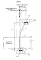
- FIG. 7 is a diagram for explaining a displacement amount of the wire electrode 4 according to the position of the wire electrode 4.
- a bending amount x of the wire electrode 4 at any height z can be calculated by the following Expression (1).
- F represents a distributed load
- T represents the tension of the wire electrode 4
- L represents the position in a z direction of the upper wire guide with respect to a lower wire guide position.
- a necessary route correction amount is calculated from the bending amount x calculated by the above Expression (1). That is, by substituting values in respective variables of Expression (1), respective displacement amounts (bending amounts x) of a workpiece upper surface and a workpiece lower surface are calculated. Positioning commands for the upper guide and the lower guide are corrected on the basis of the calculated displacement amounts. A discharge repulsion force generated by electric discharge, water pressure, and force due to a water flow act on the distributed load.
- the wire electric discharge machine 70 has a function of performing correction of corner shapes independently on an upper surface 3a and a lower surface 3b of the workpiece 3.
- the wire electric discharge machine 70 calculates, on the upper and lower surfaces 3a and 3b of the workpiece 3, on the basis of the positions of the upper and lower wire guides 13a and 13b, the thickness of the workpiece 3, and the position of the workpiece 3, from a correction amount at the time when the nozzles (the upper nozzle 9 and the lower nozzle 10) of the upper and lower wire guides 13a and 13b are closely attached to the upper and lower surfaces of the workpiece 3, a shape correction amount in a so-called open state in which the upper nozzle 9 and the lower nozzle 10 and the upper surface 3a and the lower surface 3b of the workpiece 3 are spaced apart.
- the wire electric discharge machine 70 performs shape correction according to the calculated shape correction amount.
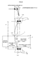
- FIG. 2 is a diagram for explaining an example in which, when an upper nozzle section (the upper nozzle 9) is closely attached to the upper surface of the workpiece 3 and a lower nozzle section (the lower nozzle 10) is also closely attached to the lower surface of the workpiece 3, an error due to bending of the wire electrode 4 is not corrected.
- a state shown in FIG. 2 is a state in which the upper and lower nozzles 9 and 10 are respectively contiguous to the upper and lower surfaces 3a and 3b of the workpiece 3.
- “Closely attached” is not a state in which the distal end of the nozzle and the surface of the workpiece are in contact with each other, but “closely attached” means that the distal end of the nozzle and the surface of the workpiece are contiguous to each other with a space enough for executing wire electric discharge machining.
- a relative position U0 in the workpiece thickness direction of the upper wire guide with respect to the upper surface 3a of the workpiece 3, a relative position L0 in the workpiece thickness direction of the lower wire guide with respect to the lower surface 3b of the workpiece 3, and a value of thickness T of the workpiece 3 at this point are stored in the storage device 51 of the controller 50 as one set of reference positions.
- a plurality of sets of reference positions are stored in the storage device 51 of the controller 50 by changing the workpiece thickness T.
- FIG. 3 is a diagram showing a table for storing, by changing the workpiece thickness T, in the storage device 51, as a set of reference positions, the workpiece thickness T, the relative position U0 in the workpiece thickness direction of the upper wire guide with respect to the upper surface 3a of the workpiece 3, and the relative position L0 in the workpiece thickness direction of the lower wire guide with respect to the lower surface 3b of the workpiece 3.
- the positions of the upper and lower wire guides and relative positions in the workpiece thickness direction of the upper and lower wire guides with respect to the workpiece upper and lower surfaces may be stored.
- an upper surface reference correction amount CU0 and a lower surface reference correction amount CL0 are respectively stored by being measured.
- the wire electrode 4 is formed in a shape passing position 100, a position 101, a position 102, and a position 103 shown in FIG. 2 .
- a machining route of the wire electrode 4 respectively shifts by bending amounts EU0 and EL0.
- FIG. 4 is a diagram for explaining an example in which, when the upper nozzle section (the upper nozzle 9) is closely attached to the upper surface of the workpiece 3 and the lower nozzle section (the lower nozzle 10) is also closely attached to the lower surface of the workpiece 3, an error due to bending of the wire electrode 4 is corrected.
- the reference position is represented as (U0, L0).
- Shape error amounts (an upper shape error amount EU0 and a lower shape error amount EL0) due to bending of the wire electrode 4 are measured after the workpiece 3 is machined in the positional relation. Note that, as shown in FIG. 2 , the upper and lower shape error amounts EU0 and EL0 can be regarded as bending amounts of the wire electrode 4 in the reference position.
- Correction amounts for correcting the machining route in order to correct the upper and lower shape error amounts EU0 and EL0 are represented as upper and lower surface reference amounts CU0 and CL0 as shown in FIG. 4 .
- the upper surface reference correction amount CU0 and the lower surface reference correction amount CL0 are calculated from a bending amount attributable to a relation between the upper and lower wire guides 13a and 13b in the closely attached state to the upper and lower surfaces of the workpiece 3 and the position of the wire electrode 4.
- the upper surface reference correction amount CU0 and the lower surface reference correction amount CL0 are substantially equal values.
- the shape error only has to be corrected according to relative movement in a plane direction of the table 2, on which the workpiece 3 is fixed, and the upper and lower guide sections (the upper wire guide 13a and the lower wire guide 13b) which stretch the wire electrode 4 in the up-down direction.
- the positions of the X axis and the Y axis of the table for relatively moving the workpiece with respect to the upper and lower guide sections only have to be corrected.
- FIG. 5 is a diagram for explaining an example in which, when the upper nozzle section is separated from the upper surface 3a of the workpiece 3 and the lower nozzle section is closely attached to the lower surface 3b of the workpiece 3, an error due to bending of the wire electrode 4 is not corrected.
- FIG. 6 is a diagram for explaining an example in which, when the upper nozzle section is separated from the upper surface 3a of the workpiece 3 and the lower nozzle section is closely attached to the lower surface 3b of the workpiece 3, an error due to bending of the wire electrode 4 is corrected.
- a distance U1 between the upper wire guide 13a and the upper surface 3a of the workpiece 3 and a distance L1 between the lower wire guide 13b and the lower surface 3b of the workpiece 3 are calculated from position information of the upper and lower surfaces 3a and 3b of the workpiece 3 and position information of the upper and lower wire guides 13a and 13b that support the wire electrode 4.
- Bending amounts of the wire electrode 4 corresponding to the calculated distances are calculated on the basis of the shape error amounts (EU0, EL0) due to a bending amount in the reference position or the reference correction amounts (CU0, CL0), which are correction amounts in the reference position.
- the calculated bending amounts or correction amounts of the wire electrode 4 are set as the bending amounts (the upper bending amount EU1 and the lower bending amount EL1) or the correction amounts (the upper surface correction amount CU1 and the lower surface correction amount CL1).
- An error due to bending of the wire electrode 4 is corrected with the bending amounts (EU1, EL1) or the correction amounts (CU1, CL1) respectively on the upper and lower surfaces 3a and 3b of the workpiece 3.
- correction amounts on the upper and lower surfaces 3a and 3b of the workpiece 3 are calculated from a relation between the upper and lower wire guides 13a and 13b and the thickness T of the workpiece 3 and a relation of the reference correction amounts (EU0, ELO).
- the above Expression (1) is modified such that deformation due to bending of the wire electrode 4 passes a position 130, a position 131, and a position 132 in FIG. 6 .
- the upper surface correction amount CU1 in the upper wire guide position U1 is calculated using the modified Expression (1).
- UV axes correction movement amounts adjusted by correction movement amounts by the X and Y axes on the lower surface and correction movement amounts by the X and Y axes on the upper surface are controlled to minimize shape errors on the upper and lower surfaces of the workpiece 3.
- the thickness of the workpiece 3 is 50 mm
- the lower surface 3b of the workpiece 3 and a lower guide section(the lower nozzle 10) are closely attached, and the upper surface 3a of the workpiece 3 and an upper guide section (the upper nozzle 9) are separated by 50 mm
- the upper bending amount EU1 and the lower bending amount EL1 which are bending amounts
- the upper surface correction amount CU1 and the lower surface correction amount CL1 which are correction amounts.
- FIG. 8 is a diagram for explaining an example in which, when the upper nozzle section (the upper nozzle 9) is separated from the upper surface 3a of the workpiece 3 and the lower nozzle section (the lower nozzle 10) is also separated from the lower surface 3b of the workpiece 3, an error due to bending of the wire electrode 4 is not corrected.
- FIG. 9 is a diagram for explaining an example in which, when the upper nozzle section (the upper nozzle 9) is separated from the upper surface 3a of the workpiece 3 and the lower nozzle section (the lower nozzle 10) is also separated from the lower surface 3b of the workpiece 3, an error due to bending of the wire electrode 4 is corrected.
- the modified Expression (1) of the wire electrode 4 that passes a position 150, a position 151, and a position 152 shown in FIG. 9 is calculated.
- the upper surface correction amount CU1 in the upper wire guide position U1 at this point is calculated.
- the distance U1 between the upper wire guide 13a and the upper surface 3a of the workpiece 3 and the distance L1 between the lower wire guide 13b and the lower surface 3b of the workpiece 3 are calculated from the position information of the upper and lower surfaces 3a and 3b of the workpiece 3 and the position information of the upper and lower wire guides 13a and 13b that support the wire electrode 4.
- Bending amounts of the wire electrode 4 corresponding to the calculated distances U1 and L1 are calculated on the basis of the bending amounts (the upper shape error amounts EU0 and the lower shape error amounts EL0) in the reference position or the reference correction amounts (the upper surface reference correction amounts CU0 and the lower surface reference correction amount CL0), which are the correction amounts in the reference position.
- the calculated bending amounts or correction amounts of the wire electrode 4 are set as the bending amounts (EU1, EL1) or the correction amounts (CU1, CL1).
- An error due to bending of the wire electrode 4 is corrected with the bending amounts (EU1, EL1) or the correction amounts (CU1, CL1) respectively on the upper and lower surfaces 3a and 3b of the workpiece 3.
- FIG. 12 is a block diagram of a main part of the wire electric discharge machine.
- the wire electric discharge machine 70 can automatically correct a machining route according to an angle formed by moving blocks that form a corner section.
- the wire electric discharge machine 70 reads a block of a machining program from a machining-program storing unit 61 in which a machining program 60 is stored, analyzes the read block, and determines, with a corner-angle detecting unit 62, whether a corner is present or not.
- the wire electric discharge machine 70 creates, in a machining-route correcting unit 63, a correction route according to the angle and causes a machining-route control unit 64 to move the wire electrode 4 relatively to the workpiece 3.
- the wire electric discharge machine 70 does not create a correction route and causes the machining-route control unit 64 to move the wire electrode 4 relatively to the workpiece 3.
- the machining-route correcting unit 63 calculates a correction distance (the correction amount explained above) and a return distance on the basis of the corner angle detected by the corner-angle detecting unit 62, extends, according to the correction distance, an end point of a block to be machined first, deletes, according to the return distance, a block to be machined next from a start point to halfway in the block, corrects the machining route to connect a new block end point created by the extension and a new block start point created by the deletion, and outputs the corrected machining route to the machining-route control unit 64 (specifically, see Japanese Patent Application Laid-Open No. 2014-121755 ).
- FIG. 13 is a flowchart showing processing in performing correction independently in the upper and lower wire guides according to the distance between the upper and lower guides according to the present invention. The processing is explained below according to steps.
- Step SB01 The thickness T of the workpiece 3, the relative position U0 in the workpiece thickness direction of the upper wire guide with respect to the upper surface 3a of the workpiece 3, and the relative position L0 in the thickness direction of the lower wire guide with respect to the lower surface 3b of the workpiece 3 in a state in which the upper nozzle and the lower nozzle are closely attached to the surface of the workpiece are stored.
- Step SB02 The upper bending amount EU1 on the workpiece upper surface 3a and the lower bending amount EL1 on the workpiece lower surface 3b of the wire electrode 4 are calculated from the information stored in step SB01, the actual distance U1 between the upper wire guide 13a and the upper surface 3a of the workpiece 3, the actual distance L1 between the lower wire guide 13b and the lower surface 3b of the workpiece 3, and the thickness T of the workpiece 3.
- Step SB03 The correction amount (the upper surface correction amount) CU1 of the upper guide position and the correction amount (the lower surface correction amount) CL1 of the lower guide position are calculated from the upper bending amount EU1 and the lower bending amount EL1 calculated in step SB02.
- Step SB04 A correction route of the upper wire guide position and the lower wire guide position is calculated from the upper surface correction amount CU1 and the lower surface correction amount CL1 calculated in step SB03.
- Step SB05 The correction route calculated in step SB04 is output. The processing is ended.
- the upper surface correction amount CU1 and the lower surface correction amount CL1 of the upper and lower wire guides 13a and 13b are calculated on the basis of the above Expression (1).
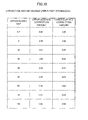
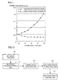
- machining route errors in combinations of many workpiece thicknesses and upper and lower guide positions may be measured by a machining test and stored as indicated in, for example, a table in FIG. 10 or a graph in FIG. 11 as the respective correction amounts.
- FIG. 14 is a diagram for explaining that a plurality of sets of relative positions (U1, L1) of the upper and lower wire guides in the workpiece thickness direction with respect to the workpiece upper and lower surfaces and the thickness T of the workpiece are stored as reference positions and that correction amounts (the upper surface correction amount CU1 and the lower surface correction amount CL1) for correcting shift amounts between wire guide coordinate positions on a machining program route in the reference positions and actual machining positions on the workpiece upper and lower surfaces due to wire bending during machining are stored.
- U1, L1 sets of relative positions of the upper and lower wire guides in the workpiece thickness direction with respect to the workpiece upper and lower surfaces and the thickness T of the workpiece
- a table shown in FIG. 14 is stored in the storage device 51 of the controller 50.
- the upper surface correction amount CU1 and the lower surface correction amount CL1 for correcting shift amounts when the thickness T of the workpiece is 5, 10, 20, and 30 (mm), the upper wire guide position (the upper surface distance) U1 is 5, 10, 20, and 30 (mm), and the lower wire guide position (the lower surface distance) L1 is 5, 10, 20, and 30 (mm) are stored.
- "CU1" and "CL1" are described in all columns. However, actually, specific values corresponding to the upper surface distance U1 and the lower surface distance L1 are stored.
- FIG. 10 is a diagram showing, as an example of FIG. 14 , correction amounts for correcting shift amounts when the upper nozzle section is separated from the upper surface 3a of the workpiece 3 and the lower nozzle section is closely attached to the lower surface 3b of the workpiece 3.
- FIG. 11 is a diagram showing FIG. 10 as a graph.
- An "upper nozzle gap” corresponds to a value obtained by subtracting the distance between the distal end portion of the upper nozzle and the wire guide from the upper wire guide position U1.
- An “upper surface correction amount” corresponds to the upper surface correction amount CU1.
- a “lower surface correction amount” corresponds to the lower surface correction amount CL1.
- the controller 50 includes a reference-position storing unit 81 that stores, as reference positions, relative positions in the workpiece thickness direction of the upper and lower wire guides with respect to the workpiece upper and lower surfaces and workpiece thickness in a state in which the upper and lower wire guides are contiguous to the machining workpiece upper and lower surfaces, a correction-amount storing unit 82 that stores correction amounts for correcting shift amounts between wire guide coordinate positions on a machining program route in the reference positions and actual machining positions on the workpiece upper and lower surfaces due to wire bending during machining, a setting unit 80 that sets relative positions in the workpiece thickness direction of the upper and lower wire guides with respect to the workpiece upper and lower surfaces in any upper and lower wire guide positions and workpiece thickness, a correction-amount calculating unit 83 that calculates, on the basis of the stored reference positions and the correction amounts, correction amounts for correcting the respective shift amounts in the set relative positions of the upper and lower wire guides in the workpiece thickness direction of the upper and lower wire guides with respect to the workpiece upper and lower surfaces and the
- the controller 50 may include a shift-amount storing unit that stores shift amounts between wire guide coordinate positions on the machining program route in the reference positions and actual machining positions on the workpiece upper and lower surfaces due to wire bending during machining and a correction-amount calculating unit that calculates correction amounts from the shift amounts stored in the shift-amount storing unit.
- a second example of the controller that controls the wire electric discharge machine main body is explained with reference to a block diagram of FIG. 16 .
- the controller 50 includes the reference-position storing unit 81 that stores a plurality of sets of relative positions in the workpiece thickness direction of the upper and lower wire guides with respect to the workpiece upper and lower surfaces and workpiece thickness, the correction-amount storing unit 82 that stores correction amounts for correcting shift amounts between wire guide coordinate positions on a machining program route in the plurality of reference positions and actual machining positions on the workpiece upper and lower surfaces due to wire bending during machining, the setting unit 80 that sets relative positions in the workpiece thickness direction of the upper and lower wire guides with respect to the workpiece upper and lower surfaces in any upper and lower wire guide positions and workpiece thickness, a selecting unit 85 that selects, from the sets of the relative positions in the workpiece thickness direction of the upper and lower wire guides with respect to the workpiece upper and lower surfaces and the workpiece thickness stored by the reference-position storing unit 81, a plurality of sets close to the set relative positions in the workpiece thickness direction of the upper and lower wire guides with respect to the workpiece upper and lower surfaces and the set thickness of the work
- the correction-amount calculating unit 83 calculates correction amounts by interpolating the upper surface correction amounts CU1 and the lower surface correction amounts CL1 respectively stored in association with the selected sets of the two reference positions.
- the controller 50 may include a shift-amount storing unit that stores shift amounts between wire guide coordinate positions on the machining program route in the plurality of reference positions and actual machining positions on the workpiece upper and lower surfaces due to wire bending during machining and a correction-amount calculating unit that calculates correction amounts from the shift amounts stored in the shift-amount storing unit.
- a third example of the controller that controls the wire electric discharge machine main body is explained with reference to a block diagram of FIG. 17 .
- the controller 50 includes the reference-position storing unit 81 that stores a plurality of sets of relative positions in workpiece thickness direction of upper and lower wire guides with respect to workpiece upper and lower surfaces and workpiece thickness, the correction-amount storing unit 82 that stores correction amounts for correcting shift amounts between wire guide coordinate positions on a machining program route in the plurality of reference positions and actual machining positions on the workpiece upper and lower surfaces due to wire bending during machining, the setting unit 80 that sets relative positions in the workpiece thickness direction of the upper and lower wire guides with respect to the workpiece upper and lower surfaces in any upper and lower wire guide positions and workpiece thickness, a correction-amount invoking unit 86 that invokes, from the stored plurality of reference positions and the correction amounts stored by the correction-amount storing unit 82, correction amounts for correcting the respective shift amounts in the set relative positions in the workpiece thickness direction of the upper and lower wire guides with respect to the workpiece upper and lower surfaces and the set workpiece thickness, and the wire-guide-position correcting unit 84 that corrects,
- the correction-amount invoking unit 86 invokes the upper surface correction amounts CU1 and the lower surface correction amounts CL1 of sets close to the set of the reference positions set by the setting unit 80.
- the controller 50 may include a shift-amount storing unit that stores shift amounts between wire guide coordinate positions on the machining program route in the plurality of reference positions and actual machining positions on the workpiece upper and lower surfaces due to wire bending during machining and a correction-amount calculating unit that calculates correction amounts from the shift amounts stored in the shift-amount storing unit.
- the controller shown in the block diagrams of FIGS. 15, 16 , and 17 may store a plurality of sets of the positions of the upper and lower wire guides and relative positions in the workpiece thickness direction of the upper and lower wire guides with respect to the workpiece upper and lower surfaces, instead of storing the plurality of sets of relative positions in the workpiece thickness direction of the upper and lower wire guides with respect to the workpiece upper and lower surfaces and workpiece thickness.
- the present invention even when one of the upper nozzle section and the lower nozzle section is separated from the upper surface 3a or the lower surface 3b of the workpiece 3 and the other is closely attached to the upper surface 3a or the lower surface 3b of the workpiece 3 or when both of the upper nozzle section and the lower nozzle section are separated from the upper surface 3a and the lower surface 3b of the workpiece 3, it is possible to minimize a machining shape error on the upper and lower surfaces of the workpiece.
- a machining time increase due to a machining speed decrease caused by an energy reduction for reducing bending in a corner section in the past does not occur. It is possible to obtain a highly efficient and highly accurate machining result.
Landscapes
- Engineering & Computer Science (AREA)
- Mechanical Engineering (AREA)
- Chemical & Material Sciences (AREA)
- Chemical Kinetics & Catalysis (AREA)
- Electrochemistry (AREA)
- Automation & Control Theory (AREA)
- Electrical Discharge Machining, Electrochemical Machining, And Combined Machining (AREA)
Abstract
Description
- The present invention relates to a wire electric discharge machine and, more particularly, to a wire electric discharge machine capable of reducing a shape error due to bending of a wire electrode on the upper and lower surfaces of workpiece and attaining improvement in shape accuracy of the workpiece by correcting, independently in an upper guide section and a lower guide section, the positions of upper and lower wire guides in a relative movement command of a wire guide with respect to the workpiece commanded by a machining program.
- In wire electric discharge machining, it is known that a wire electrode bends in the opposite direction of a machining progress direction or a direction at a fixed angle from the machining progress direction because of a discharge repulsion force that occurs between the wire electrode and a workpiece, a turbulent flow of machining liquid, or the like. When workpiece is linearly machined by the wire electrode, although bending of the wire electrode occurs in a direction opposite to the machining progress direction, the bending of the wire electrode does not affect a machining shape. However, large influence of the bending of the wire electrode appears in machining of a corner section machined at a predetermined angle set in a machining program and greatly deteriorates shape accuracy of the corner section. So-called "corner sagging" occurs. An intended machined shape is not obtained.
-
FIG. 18 is a diagram for explaining machining of a corner section. In the wire electric discharge machining, in order to machineworkpiece 3 in dimensions as desired, in general, an offset route is created by adding the radius of awire electrode 4 and a discharge gap to dimensions of an actual product shape and thewire electrode 4 is moved along the created offset route (a machining route 5). Note that a value obtained by adding up the radius of thewire electrode 4 and the discharge gap is referred to as offset value. - As shown in
FIG. 18 , since thewire electrode 4 bends in a corner section of theworkpiece 3, thewire electrode 4 does not move along themachining route 5 and moves on the inner side of the machining route (see atrack 6a of the wire electrode indicated by a broken line). As a result, thewire electrode 4 excessively machines theworkpiece 3. Therefore, so-called "corner sagging" (see corner sagging 7 due to bending of the wire electrode) is formed. A desired machining finish shape is not obtained. So, various measures have been proposed to cope with such a problem. -
Japanese Patent Application Laid-Open No. 58-120428 Japanese Patent Application Laid-Open No. 8-39356 Japanese Patent Application Laid-Open No. 7-24645 - In the machining method, the machining energy is reduced, that is, machining speed is reduced until the bending of the wire electrode decreases. The corner section is machined slowly. Therefore, there is a disadvantage that a machining time is long.
-
Japanese Patent Application Laid-Open No. 8-39356 Japanese Patent Application Laid-Open No. 7-24645 Japanese Patent Application Laid-Open No. 11-221719 Japanese Patent Application Laid-Open No. 2013-190854 - As shown in
FIG. 19 , when themachining route 5 of thewire electrode 4 is corrected by acorrection route 8 to perform the wire electric discharge machining, thewire electrode 4 moves along awire electrode track 6b. Consequently, it is possible to prevent theworkpiece 3 from being excessively machined. -
FIG. 20 is a flowchart of processing for calculating and outputting a correction route on the basis of the distance between upper and lower wire guides according to the related art. In this processing, correction is not performed independently in the upper and lower wire guides. - Information concerning the thickness of workpiece and an upper wire guide position and a lower wire guide position in a state in which upper and lower nozzles are closely attached to the workpiece is acquired (step SA01). A correction amount C is calculated according to a bending amount E of a wire electrode in the state in which the upper and lower nozzles are closely attached to the workpiece (step SA02). A true correction amount C is calculated from the calculated correction amount C and angle information of a corner section (step SA03). A correction route is calculated on the basis of the calculated true correction amount C (step SA04). The calculated correction route is output (step SA05). Then, this processing is ended.
- In the measures of both of
Japanese Patent Application Laid-Open No. 7-24645 Japanese Patent Application Laid-Open No. 11-221719 - However, machining by the wire electric discharge machine is not always machining in which the guide sections and the nozzles are closely attached to the upper and lower surfaces of the workpiece. For example, in some case, the lower surface of the workpiece is fixed on a fixed table (closely attached to the fixed table) and, on the other hand, the upper guide section is greatly apart from the workpiece upper surface because of a fixing jig or other reasons.
- When the upper guide section for supporting the wire electrode is greatly apart from the workpiece upper surface and the lower guide section for supporting the wire electrode is closely attached to the workpiece lower surface, on the workpiece lower surface, a shape correction amount in the corner section may be the correction amount itself, that is, a shape correction block. However, on the workpiece upper surface, bending due to vibration of the wire electrode further increases. Therefore, correction of the workpiece upper surface is not correctly performed even if the shape of the workpiece lower surface is corrected. Consequently, improvement of shape accuracy of a machining shape of the workpiece is insufficient.
- Therefore, it is an object of the present invention to provide a wire electric discharge machine capable of eliminating, on upper and lower surfaces of workpiece, a machining shape error of the workpiece caused by bending of a wire electrode by correcting the positions of upper and lower wire guides, which guide the wire electrode, independently on the workpiece upper and lower surfaces from a program route and attaining improvement of shape accuracy in corner sections of the workpiece upper and lower surfaces.
- The wire electric discharge machine according to the present invention stretches the wire electrode between the upper and lower wire guides and relatively moves the wire electrode with respect to the workpiece on the basis of a machining program to perform electric discharge machining.
- A wire electric discharge machine according to a first aspect of the present invention includes: a reference-position storing unit configured to store, as a reference position, relative positions in a workpiece thickness direction of upper and lower wire guides with respect to workpiece upper and lower surfaces and the thickness of workpiece in a state in which the upper and lower wire guides respectively approach the upper and lower surfaces of the workpiece; a correction-amount storing unit configured to store correction amounts for correcting shift amounts between wire guide coordinate positions on a machining program route in the reference position and actual machining positions on the workpiece upper and lower surfaces, with the shift being caused by wire bending during machining; a setting unit configured to set relative positions in the workpiece thickness direction of the upper and lower wire guides with respect to the workpiece upper and lower surfaces in any upper and lower wire guide positions and the thickness of the workpiece; a correction-amount calculating unit configured to calculate, on the basis of the reference position stored in the reference-position storing unit and the correction amounts stored in the correction-amount storing unit, correction amounts for correcting the respective shift amounts in the relative positions in the workpiece thickness direction of the upper and lower wire guides with respect to the workpiece upper and lower surfaces and the thickness of the workpiece set by the setting unit; and a wire-guide-position correcting unit configured to correct, on the basis of the correction amounts calculated by the correction-amount calculating unit, independently in an upper guide section and a lower guide section, the positions of the upper and lower wire guides in a relative movement command of a wire guide with respect to the workpiece commanded by the machining program.
- A wire electric discharge machine according to a second aspect of the present invention includes: a reference-position storing unit configured to store, as reference positions, a plurality of sets of relative positions in a workpiece thickness direction of upper and lower wire guides with respect to workpiece upper and lower surfaces and the thickness of workpiece; a correction-amount storing unit configured to store correction amounts for correcting shift amounts between wire guide coordinate positions on a machining program route in a plurality of the reference positions and actual machining positions on the workpiece upper and lower surfaces, with the shift being caused by wire bending during machining; a setting unit configured to set relative positions in the workpiece thickness direction of the upper and lower wire guides with respect to the workpiece upper and lower surfaces in any upper and lower wire guide positions and the thickness of the workpiece; a selecting unit configured to select, from the sets of the relative positions in the workpiece thickness direction of the upper and lower wire guides with respect to the workpiece upper and lower surfaces and the thickness of the workpiece stored in the reference-position storing unit, a plurality of sets of those close to the relative positions in the workpiece thickness direction of the upper and lower wire guides with respect to the workpiece upper and lower surfaces and the thickness of the workpiece set by the setting unit; a correction-amount calculating unit configured to calculate, on the basis of the plurality of reference positions in the plurality of sets selected by the selecting unit and the correction amounts stored in the correction-amount storing unit, correction amounts for correcting the respective shift amounts in the relative positions in the workpiece thickness direction of the upper and lower wire guides with respect to the workpiece upper and lower surfaces and the thickness of the workpiece set by the setting unit; and a wire-guide-position correcting unit configured to correct, on the basis of the correction amounts calculated by the correction-amount calculating unit, independently in an upper guide section and a lower guide section, the positions of the upper and lower wire guides in a relative movement command of a wire guide with respect to the workpiece commanded by the machining program.
- A wire electric discharge machine according to a third aspect of the present invention includes: a reference-position storing unit configured to store, as reference positions, a plurality of sets of relative positions in workpiece thickness direction of upper and lower wire guides with respect to workpiece upper and lower surfaces and the thickness of workpiece; a correction-amount storing unit configured to store correction amounts for correcting shift amounts between wire guide coordinate positions on a machining program route in a plurality of the reference positions and actual machining positions on the workpiece upper and lower surfaces, with the shift being caused by wire bending during machining; a setting unit configured to set relative positions in the workpiece thickness direction of the upper and lower wire guides with respect to the workpiece upper and lower surfaces in any upper and lower wire guide positions and the thickness of the workpiece; a correction-amount invoking unit configured to invoke, from the plurality of reference positions stored in the reference-position storing unit and the correction amounts stored in the correction-amount storing unit, correction amounts for correcting the respective shift amounts in the relative positions in the workpiece thickness direction of the upper and lower wire guides with respect to the workpiece upper and lower surfaces and the thickness of the workpiece set by the setting unit; and a wire-guide-position correcting unit configured to correct, on the basis of the correction amounts invoked by the correction-amount invoking unit, independently in an upper guide section and a lower guide section, the positions of the upper and lower wire guides in a relative movement command of a wire guide with respect to the workpiece commanded by the machining program.
- A wire electric discharge machine according to a fourth aspect of the present invention includes: a reference-position storing unit configured to store, as a reference position, relative positions in a workpiece thickness direction of upper and lower wire guides with respect to workpiece upper and lower surfaces and the thickness of workpiece in a state in which the upper and lower wire guides respectively approach the upper and lower surfaces of the workpiece; a shift-amount storing unit configured to store shift amounts between wire guide coordinate positions on a machining program route in the reference position and actual machining positions on the workpiece upper and lower surfaces, with the shift being caused by wire bending during machining; a correction-amount calculating unit configured to calculate correction amounts from the shift amounts stored in the shift-amount storing unit; a setting unit configured to set relative positions in the workpiece thickness direction of the upper and lower wire guides with respect to the workpiece upper and lower surfaces in any upper and lower wire guide positions and the thickness of the workpiece; a correction-amount calculating unit configured to calculate, on the basis of the reference position stored in the reference-position storing unit and the correction amounts calculated by the correction-amount calculating unit, correction amounts for correcting the respective shift amounts in the relative positions in the workpiece thickness direction of the upper and lower wire guides with respect to the workpiece upper and lower surfaces and the thickness of the workpiece set by the setting unit; and a wire-guide-position correcting unit configured to correct, on the basis of the correction amounts calculated by the correction-amount calculating unit, independently in an upper guide section and a lower guide section, the positions of the upper and lower wire guides in a relative movement command of a wire guide with respect to the workpiece commanded by the machining program.
- A wire electric discharge machine according to a fifth aspect of the present invention includes: a reference-position storing unit configured to store, as reference positions, a plurality of sets of relative positions in a workpiece thickness direction of upper and lower wire guides with respect to workpiece upper and lower surfaces and the thickness of workpiece; a shift-amount storing unit configured to store shift amounts between wire guide coordinate positions on a machining program route in a plurality of the reference positions and actual machining positions on the workpiece upper and lower surfaces, with the shift being caused by wire bending during machining; a correction-amount calculating unit configured to calculate correction amounts from the shift amounts stored in the shift-amount storing unit; a setting unit configured to set relative positions in the workpiece thickness direction of the upper and lower wire guides with respect to the workpiece upper and lower surfaces in any upper and lower wire guide positions and the thickness of the workpiece; a selecting unit configured to select, from the sets of the relative positions in the workpiece thickness direction of the upper and lower wire guides with respect to the workpiece upper and lower surfaces and the thickness of the workpiece stored in the reference-position storing unit, a plurality of sets of those close to the relative positions in the workpiece thickness direction of the upper and lower wire guides with respect to the workpiece upper and lower surfaces and the thickness of the workpiece set by the setting unit; a correction-amount calculating unit configured to calculate, on the basis of the plurality of reference positions in the plurality of sets selected by the selecting unit and the correction amounts stored in the correction-amount storing unit, correction amounts for correcting the respective shift amounts in the relative positions in the workpiece thickness direction of the upper and lower wire guides with respect to the workpiece upper and lower surfaces and the thickness of the workpiece set by the setting unit; and a wire-guide-position correcting unit configured to correct, on the basis of the correction amounts calculated by the correction-amount calculating unit, independently in an upper guide section and a lower guide section, the positions of the upper and lower wire guides in a relative movement command of a wire guide with respect to the workpiece commanded by the machining program.
- A wire electric discharge machine according to a sixth aspect of the present invention includes: a reference-position storing unit configured to store, as reference positions, a plurality of sets of relative positions in workpiece thickness direction of upper and lower wire guides with respect to workpiece upper and lower surfaces and the thickness of workpiece; a shift-amount storing unit configured to store shift amounts between wire guide coordinate positions on a machining program route in a plurality of the reference positions and actual machining positions on the workpiece upper and lower surfaces, with the shift being caused by wire bending during machining; a correction-amount calculating unit configured to calculate correction amounts from the shift amounts stored in the shift-amount storing unit; a setting unit configured to set relative positions in the workpiece thickness direction of the upper and lower wire guides with respect to the workpiece upper and lower surfaces in any upper and lower wire guide positions and the thickness of the workpiece; a correction-amount invoking unit configured to invoke, from the plurality of reference positions stored in the reference-position storing unit and the correction amounts calculated by the correction-amount calculating unit, correction amounts for correcting the respective shift amounts in the relative positions in the workpiece thickness direction of the upper and lower wire guides with respect to the workpiece upper and lower surfaces and the thickness of the workpiece set by the setting unit; and a wire-guide-position correcting unit configured to correct, on the basis of the correction amounts invoked by the correction-amount invoking unit, independently in an upper guide section and a lower guide section, the positions of the upper and lower wire guides in a relative movement command of a wire guide with respect to the workpiece commanded by the machining program.
- The reference-position storing unit can be configured to store a plurality of sets of the positions of the upper and lower wire guides and the relative positions in the workpiece thickness direction of the upper and lower wire guides with respect to the workpiece upper and lower surfaces instead of storing the plurality of sets of the relative positions in the workpiece thickness direction of the upper and lower wire guides with respect to the workpiece upper and lower surfaces.
- According to the present invention, it is possible to provide a wire electric discharge machine capable of eliminating, on upper and lower surfaces of workpiece, a machining shape error of the workpiece caused by bending of a wire electrode by correcting the positions of upper and lower wire guides, which guide the wire electrode, independently on the workpiece upper and lower surfaces from a program route and attaining improvement of shape accuracy in corner sections of the workpiece upper and lower surfaces.
- The objects and features described above and other objects and features of the present invention will be made apparent from the following explanation of embodiments with reference to the accompanying drawings, among the figures:
-
FIG. 1 is a schematic configuration diagram of a wire electric discharge machine; -
FIG. 2 is a diagram for explaining an example in which, when an upper nozzle section is closely attached to a workpiece upper surface and a lower nozzle section is closely attached to a workpiece lower surface, an error due to bending of a wire electrode is not corrected; -
FIG. 3 is a diagram showing a table for storing, by changing workpiece thickness, in a storage device, as a set of reference positions, the workpiece thickness, a relative position in a workpiece thickness direction with respect to the upper surface of the workpiece, and a relative position in the workpiece thickness direction with respect to the lower surface of the workpiece; -
FIG. 4 is a diagram for explaining an example in which, when the upper nozzle section is closely attached to the workpiece upper surface and the lower nozzle section is closely attached to the workpiece lower surface, an error due to bending of the wire electrode is corrected; -
FIG. 5 is a diagram for explaining an example in which, when the upper nozzle section is separated from the workpiece upper surface and the lower nozzle section is closely attached to the workpiece lower surface, an error due to bending of the wire electrode is not corrected; -
FIG. 6 is a diagram for explaining an example in which, when the upper nozzle section is separated from the workpiece upper surface and the lower nozzle section is closely attached to the workpiece lower surface, an error due to bending of the wire electrode is corrected; -
FIG. 7 is a diagram for explaining a displacement amount of the wire electrode due to a workpiece position; -
FIG. 8 is a diagram for explaining an example in which, when the upper nozzle section is separated from the workpiece upper surface and the lower nozzle section is separated from the workpiece lower surface, an error due to bending of the wire electrode is not corrected; -
FIG. 9 is a diagram for explaining an example in which, when the upper nozzle section is separated from the workpiece upper surface and the lower nozzle section is separated from the workpiece lower surface, an error due to bending of the wire electrode is corrected; -
FIG. 10 is a diagram showing a correction amount during upper part opening when the upper nozzle section is separated from the workpiece upper surface; -
FIG. 11 is a diagram showingFIG. 10 as a graph; -
FIG. 12 is a block diagram of a main part of the wire electric discharge machine; -
FIG. 13 is a flowchart showing processing in performing correction independently in upper and lower guides according to the distance between the upper and lower guides; -
FIG. 14 is a diagram for explaining that a plurality of sets of relative positions of upper and lower wire guides in the workpiece thickness direction with respect to the workpiece upper and lower surfaces and the workpiece thickness are stored as reference positions and correction amounts in the reference positions are stored; -
FIG. 15 is a block diagram for explaining a first example of a controller that controls a main body of the wire electric discharge machine according to the present invention; -
FIG. 16 is a block diagram for explaining a second example of the controller that controls the main body of the wire electric discharge machine according to the present invention; -
FIG. 17 is a block diagram for explaining a third example of the controller that controls the main body of the wire electric discharge machine according to the present invention; -
FIG. 18 is a diagram for explaining machining of a corner section; -
FIG. 19 is a diagram for explaining a method of correcting a machining route in order to prevent workpiece from being excessively machined because of bending of a wire electrode; and -
FIG. 20 is a flowchart for explaining processing in not performing correction independently in upper and lower guides according to the distance between the upper and lower guides. -
FIG. 1 is a schematic configuration diagram of a wire electric discharge machine. - A wire
electric discharge machine 70 generates electric discharge between awire electrode 4 andworkpiece 3, which is a workpiece, placed on a table 2 to perform machining of theworkpiece 3. The wireelectric discharge machine 70 includes, on abase 20, anX-axis saddle 19 that moves in an X-axis direction with aball screw 31 driven by anX-axis motor 26. The wireelectric discharge machine 70 includes, on theX-axis saddle 19, a Y-axis saddle 18 that moves in a Y-axis direction with aball screw 30 driven by a Y-axis motor 25. Amachining tank 14 including the table 2, on which theworkpiece 3 is placed, on the inside is fixed on the Y-axis saddle 18. - A
column 21 is provided perpendicularly to thebase 20. Alower arm 42 is horizontally attached to a side surface section of thecolumn 21. Alower nozzle 10 and alower wire guide 13b are attached to the distal end of thelower arm 42. Thelower nozzle 10 and thelower wire guide 13b are located below the table 2. Thecolumn 21 includes a V-axis saddle 15 in an upper part thereof. The V-axis saddle 15 moves in a V-axis direction with aball screw 34 driven by a V-axis motor 29. The V-axis direction is the same as the Y-axis direction. A U-axis table 16 is attached to the V-axis saddle 15. The U-axis table 16 moves in a U-axis direction with aball screw 33 driven by aU-axis motor 28. The U-axis direction is the same as the X-axis direction. - An upper-
arm supporting member 17 is attached to the U-axis table 16. The upper-arm supporting member 17 moves in a Z-axis direction with aball screw 32 driven by a Z-axis motor 27. Anupper arm 41 is fixed to the upper-arm supporting member 17. Anupper nozzle 9 and anupper wire guide 13a are attached to an end of theupper arm 41. The Y-axis motor 25, theX-axis motor 26, the Z-axis motor 27, theU-axis motor 28, and the V-axis motor 29 are respectively connected to acontroller 50 by power/signal lines controller 50 including an amplifier (not-shown). Various signals are exchanged between the motors and thecontroller 50. Note that, inFIG. 1 , the X axis and the U axis are directions perpendicular to the paper surface, the Y axis and the V axis are the left-right direction on the paper surface, and the Z axis is the up-down direction on the paper surface. - The
machining tank 14 is attached on the Y-axis saddle 18. The table 2 is disposed in a tank of themachining tank 14. - The
workpiece 3 is fixed to the table 2. Electric discharge machining is executed in a state in whichmachining liquid 11 is stored in themachining tank 14. Theupper nozzle 9 jets themachining liquid 11 to an upper part of theworkpiece 3. Thelower nozzle 10 jets themachining liquid 11 to a lower part of theworkpiece 3. Theupper wire guide 13a in theupper nozzle 9 supports thewire electrode 4 in the upper part of theworkpiece 3. Thelower wire guide 13b in thelower nozzle 10 supports thewire electrode 4 in the lower part of theworkpiece 3. - The wire
electric discharge machine 70 performs electric discharge between thewire electrode 4 and theworkpiece 3 via themachining liquid 11. In order to perform stable electric discharge machining, in the wire electric discharge machine 70 amachining liquid pump 43 pumps up themachining liquid 11 from a storage tank (not shown) for storing themachining liquid 11 and jets themachining liquid 11 to a machined part at high pressure from theupper nozzle 9 and thelower nozzle 10 through aconduit 22, aconduit 23, and aconduit 24. The wireelectric discharge machine 70 performs wire electric discharge machining while blowing off machining waste in a machining groove 12 with the jetted machiningliquid 11. - The
machining liquid pump 43 is connected to thecontroller 50 including the amplifier (not-shown) by a power/signal line 40 and is controlled and driven by thecontroller 50. Electric power is supplied from thecontroller 50 to themachining liquid pump 43. Exchange of signals is performed between thecontroller 50 and themachining liquid pump 43. Themachining liquid pump 43 supplies themachining liquid 11 to theupper nozzle 9 via thebranch conduit 22 and theconduit 23 and also supplies themachining liquid 11 to thelower nozzle 10 via thebranch conduit 22 and theconduit 24. Themachining liquid 11 is jetted to the machined part being discharge-machined from theupper nozzle 9 and thelower nozzle 10. - The
controller 50 is a device that comprehensively controls the wireelectric discharge machine 70. Thecontroller 50 includes an arithmetic device, a display device, an interface for input and output of various signals, and an amplifier, all of which are not shown in the figure, and includes a storage device 51 that stores various data. InFIG. 1 , the arithmetic device, the display device, the interface for input and output of various signals, and the amplifier are collectively shown as anarithmetic processing device 52. - During the electric discharge machining, the
wire electrode 4 bends in the direction opposite to a relative movement direction of thewire electrode 4 with respect to theworkpiece 3 due to machining liquid pressure and a discharge repulsion force (seeFIG. 2 ). It is seen from a machining test that deformation due to the bending of thewire electrode 4 is a shape same as vibration of a string. The shape is equal to displacement of a beam that receives uniformly distributed load with both ends supported.FIG. 7 is a diagram for explaining a displacement amount of thewire electrode 4 according to the position of thewire electrode 4. A bending amount x of thewire electrode 4 at any height z can be calculated by the following Expression (1).
- In the expression, F represents a distributed load, T represents the tension of the
wire electrode 4, and L represents the position in a z direction of the upper wire guide with respect to a lower wire guide position. - A necessary route correction amount is calculated from the bending amount x calculated by the above Expression (1). That is, by substituting values in respective variables of Expression (1), respective displacement amounts (bending amounts x) of a workpiece upper surface and a workpiece lower surface are calculated. Positioning commands for the upper guide and the lower guide are corrected on the basis of the calculated displacement amounts. A discharge repulsion force generated by electric discharge, water pressure, and force due to a water flow act on the distributed load.
- The wire
electric discharge machine 70 has a function of performing correction of corner shapes independently on anupper surface 3a and alower surface 3b of theworkpiece 3. The wireelectric discharge machine 70 calculates, on the upper andlower surfaces workpiece 3, on the basis of the positions of the upper and lower wire guides 13a and 13b, the thickness of theworkpiece 3, and the position of theworkpiece 3, from a correction amount at the time when the nozzles (theupper nozzle 9 and the lower nozzle 10) of the upper and lower wire guides 13a and 13b are closely attached to the upper and lower surfaces of theworkpiece 3, a shape correction amount in a so-called open state in which theupper nozzle 9 and thelower nozzle 10 and theupper surface 3a and thelower surface 3b of theworkpiece 3 are spaced apart. The wireelectric discharge machine 70 performs shape correction according to the calculated shape correction amount. -
FIG. 2 is a diagram for explaining an example in which, when an upper nozzle section (the upper nozzle 9) is closely attached to the upper surface of theworkpiece 3 and a lower nozzle section (the lower nozzle 10) is also closely attached to the lower surface of theworkpiece 3, an error due to bending of thewire electrode 4 is not corrected. A state shown inFIG. 2 is a state in which the upper andlower nozzles lower surfaces workpiece 3. "Closely attached" is not a state in which the distal end of the nozzle and the surface of the workpiece are in contact with each other, but "closely attached" means that the distal end of the nozzle and the surface of the workpiece are contiguous to each other with a space enough for executing wire electric discharge machining. - A relative position U0 in the workpiece thickness direction of the upper wire guide with respect to the
upper surface 3a of theworkpiece 3, a relative position L0 in the workpiece thickness direction of the lower wire guide with respect to thelower surface 3b of theworkpiece 3, and a value of thickness T of theworkpiece 3 at this point are stored in the storage device 51 of thecontroller 50 as one set of reference positions. A plurality of sets of reference positions are stored in the storage device 51 of thecontroller 50 by changing the workpiece thickness T. -
FIG. 3 is a diagram showing a table for storing, by changing the workpiece thickness T, in the storage device 51, as a set of reference positions, the workpiece thickness T, the relative position U0 in the workpiece thickness direction of the upper wire guide with respect to theupper surface 3a of theworkpiece 3, and the relative position L0 in the workpiece thickness direction of the lower wire guide with respect to thelower surface 3b of theworkpiece 3. Instead of the thickness of the workpiece, the positions of the upper and lower wire guides and relative positions in the workpiece thickness direction of the upper and lower wire guides with respect to the workpiece upper and lower surfaces may be stored. In the reference positions, an upper surface reference correction amount CU0 and a lower surface reference correction amount CL0 are respectively stored by being measured. - In the reference positions of [the lower wire guide position L0, the workpiece thickness T, the upper wire guide position U0], the
wire electrode 4 is formed in ashape passing position 100, aposition 101, aposition 102, and aposition 103 shown inFIG. 2 . On theupper surface 3a and thelower surface 3b of theworkpiece 3, a machining route of thewire electrode 4 respectively shifts by bending amounts EU0 and EL0. - Therefore, in order to eliminate a machining error (see
FIG. 2 ) of the bending amounts EU0 and EL0, as shown inFIG. 4 , a moving route on the machining route of thewire electrode 4 is changed by the upper surface reference correction amount CU0 on theupper surface 3a of theworkpiece 3 and changed by the lower surface reference correction amount CL0 on thelower surface 3b.FIG. 4 is a diagram for explaining an example in which, when the upper nozzle section (the upper nozzle 9) is closely attached to the upper surface of theworkpiece 3 and the lower nozzle section (the lower nozzle 10) is also closely attached to the lower surface of theworkpiece 3, an error due to bending of thewire electrode 4 is corrected. - When the
workpiece 3 is machined in a state in which upper and lower machining liquid jetting nozzles (theupper nozzle 9 and the lower nozzle 10) are closely attached to the upper andlower surfaces workpiece 3 having the thickness T to be machined, the distances between the upper and lower wire guides 13a and 13b, which support thewire electrode 4 in upper and lower parts thereof, and the upper andlower surfaces workpiece 3 are respectively represented as U0 and L0. A positional relation between the upper and lower wire guides 13a and 13b and theworkpiece 3 in a state in which the upper andlower nozzles upper surface 3a and thelower surface 3b of theworkpiece 3 is referred to as "reference position". The reference position is represented as (U0, L0). Shape error amounts (an upper shape error amount EU0 and a lower shape error amount EL0) due to bending of thewire electrode 4 are measured after theworkpiece 3 is machined in the positional relation. Note that, as shown inFIG. 2 , the upper and lower shape error amounts EU0 and EL0 can be regarded as bending amounts of thewire electrode 4 in the reference position. - Correction amounts for correcting the machining route in order to correct the upper and lower shape error amounts EU0 and EL0 are represented as upper and lower surface reference amounts CU0 and CL0 as shown in
FIG. 4 . As shown inFIG. 4 , the upper surface reference correction amount CU0 and the lower surface reference correction amount CL0 are calculated from a bending amount attributable to a relation between the upper and lower wire guides 13a and 13b in the closely attached state to the upper and lower surfaces of theworkpiece 3 and the position of thewire electrode 4. In this case, the upper surface reference correction amount CU0 and the lower surface reference correction amount CL0 are substantially equal values. When a shape error is corrected, the shape error only has to be corrected according to relative movement in a plane direction of the table 2, on which theworkpiece 3 is fixed, and the upper and lower guide sections (theupper wire guide 13a and thelower wire guide 13b) which stretch thewire electrode 4 in the up-down direction. In the configuration of the wireelectric discharge machine 70 shown inFIG. 1 , the positions of the X axis and the Y axis of the table for relatively moving the workpiece with respect to the upper and lower guide sections only have to be corrected. -
FIG. 5 is a diagram for explaining an example in which, when the upper nozzle section is separated from theupper surface 3a of theworkpiece 3 and the lower nozzle section is closely attached to thelower surface 3b of theworkpiece 3, an error due to bending of thewire electrode 4 is not corrected.FIG. 6 is a diagram for explaining an example in which, when the upper nozzle section is separated from theupper surface 3a of theworkpiece 3 and the lower nozzle section is closely attached to thelower surface 3b of theworkpiece 3, an error due to bending of thewire electrode 4 is corrected. - When the upper and lower nozzle sections (the
upper nozzle 9 and the lower nozzle 10) cannot be closely attached to the upper andlower surfaces workpiece 3 to be machined, a distance U1 between theupper wire guide 13a and theupper surface 3a of theworkpiece 3 and a distance L1 between thelower wire guide 13b and thelower surface 3b of theworkpiece 3 are calculated from position information of the upper andlower surfaces workpiece 3 and position information of the upper and lower wire guides 13a and 13b that support thewire electrode 4. - Bending amounts of the
wire electrode 4 corresponding to the calculated distances are calculated on the basis of the shape error amounts (EU0, EL0) due to a bending amount in the reference position or the reference correction amounts (CU0, CL0), which are correction amounts in the reference position. The calculated bending amounts or correction amounts of thewire electrode 4 are set as the bending amounts (the upper bending amount EU1 and the lower bending amount EL1) or the correction amounts (the upper surface correction amount CU1 and the lower surface correction amount CL1). An error due to bending of thewire electrode 4 is corrected with the bending amounts (EU1, EL1) or the correction amounts (CU1, CL1) respectively on the upper andlower surfaces workpiece 3. - In the case of
FIG. 6 , correction amounts on the upper andlower surfaces workpiece 3 are calculated from a relation between the upper and lower wire guides 13a and 13b and the thickness T of theworkpiece 3 and a relation of the reference correction amounts (EU0, ELO). The above Expression (1) is modified such that deformation due to bending of thewire electrode 4 passes aposition 130, aposition 131, and aposition 132 inFIG. 6 . The upper surface correction amount CU1 in the upper wire guide position U1 is calculated using the modified Expression (1). UV axes correction movement amounts adjusted by correction movement amounts by the X and Y axes on the lower surface and correction movement amounts by the X and Y axes on the upper surface are controlled to minimize shape errors on the upper and lower surfaces of theworkpiece 3. - For example, when the thickness of the
workpiece 3 is 50 mm, thelower surface 3b of theworkpiece 3 and a lower guide section(the lower nozzle 10) are closely attached, and theupper surface 3a of theworkpiece 3 and an upper guide section (the upper nozzle 9) are separated by 50 mm, by calculating a positional shift amount at points where a shape line of displacement of thewire electrode 4 and the upper andlower surfaces workpiece 3 overlap each other, it is possible to calculate the upper bending amount EU1 and the lower bending amount EL1, which are bending amounts, or the upper surface correction amount CU1 and the lower surface correction amount CL1, which are correction amounts. -
FIG. 8 is a diagram for explaining an example in which, when the upper nozzle section (the upper nozzle 9) is separated from theupper surface 3a of theworkpiece 3 and the lower nozzle section (the lower nozzle 10) is also separated from thelower surface 3b of theworkpiece 3, an error due to bending of thewire electrode 4 is not corrected.FIG. 9 is a diagram for explaining an example in which, when the upper nozzle section (the upper nozzle 9) is separated from theupper surface 3a of theworkpiece 3 and the lower nozzle section (the lower nozzle 10) is also separated from thelower surface 3b of theworkpiece 3, an error due to bending of thewire electrode 4 is corrected. As in <2> above, the modified Expression (1) of thewire electrode 4 that passes aposition 150, aposition 151, and aposition 152 shown inFIG. 9 is calculated. The upper surface correction amount CU1 in the upper wire guide position U1 at this point is calculated. - When the upper and lower nozzle sections(the
upper nozzle 9 and the lower nozzle 10) cannot be closely attached to the upper andlower surfaces workpiece 3 to be machined, the distance U1 between theupper wire guide 13a and theupper surface 3a of theworkpiece 3 and the distance L1 between thelower wire guide 13b and thelower surface 3b of theworkpiece 3 are calculated from the position information of the upper andlower surfaces workpiece 3 and the position information of the upper and lower wire guides 13a and 13b that support thewire electrode 4. - Bending amounts of the
wire electrode 4 corresponding to the calculated distances U1 and L1 are calculated on the basis of the bending amounts (the upper shape error amounts EU0 and the lower shape error amounts EL0) in the reference position or the reference correction amounts (the upper surface reference correction amounts CU0 and the lower surface reference correction amount CL0), which are the correction amounts in the reference position. The calculated bending amounts or correction amounts of thewire electrode 4 are set as the bending amounts (EU1, EL1) or the correction amounts (CU1, CL1). An error due to bending of thewire electrode 4 is corrected with the bending amounts (EU1, EL1) or the correction amounts (CU1, CL1) respectively on the upper andlower surfaces workpiece 3. -
FIG. 12 is a block diagram of a main part of the wire electric discharge machine. - The wire
electric discharge machine 70 according to the present invention can automatically correct a machining route according to an angle formed by moving blocks that form a corner section. The wireelectric discharge machine 70 reads a block of a machining program from a machining-program storing unit 61 in which amachining program 60 is stored, analyzes the read block, and determines, with a corner-angle detecting unit 62, whether a corner is present or not. When a corner is present, the wireelectric discharge machine 70 creates, in a machining-route correcting unit 63, a correction route according to the angle and causes a machining-route control unit 64 to move thewire electrode 4 relatively to theworkpiece 3. When a corner is absent, the wireelectric discharge machine 70 does not create a correction route and causes the machining-route control unit 64 to move thewire electrode 4 relatively to theworkpiece 3. - The machining-
route correcting unit 63 calculates a correction distance (the correction amount explained above) and a return distance on the basis of the corner angle detected by the corner-angle detecting unit 62, extends, according to the correction distance, an end point of a block to be machined first, deletes, according to the return distance, a block to be machined next from a start point to halfway in the block, corrects the machining route to connect a new block end point created by the extension and a new block start point created by the deletion, and outputs the corrected machining route to the machining-route control unit 64 (specifically, seeJapanese Patent Application Laid-Open No. 2014-121755 -
FIG. 13 is a flowchart showing processing in performing correction independently in the upper and lower wire guides according to the distance between the upper and lower guides according to the present invention. The processing is explained below according to steps. - [Step SB01] The thickness T of the
workpiece 3, the relative position U0 in the workpiece thickness direction of the upper wire guide with respect to theupper surface 3a of theworkpiece 3, and the relative position L0 in the thickness direction of the lower wire guide with respect to thelower surface 3b of theworkpiece 3 in a state in which the upper nozzle and the lower nozzle are closely attached to the surface of the workpiece are stored. - [Step SB02] The upper bending amount EU1 on the workpiece
upper surface 3a and the lower bending amount EL1 on the workpiecelower surface 3b of thewire electrode 4 are calculated from the information stored in step SB01, the actual distance U1 between theupper wire guide 13a and theupper surface 3a of theworkpiece 3, the actual distance L1 between thelower wire guide 13b and thelower surface 3b of theworkpiece 3, and the thickness T of theworkpiece 3. - [Step SB03] The correction amount (the upper surface correction amount) CU1 of the upper guide position and the correction amount (the lower surface correction amount) CL1 of the lower guide position are calculated from the upper bending amount EU1 and the lower bending amount EL1 calculated in step SB02.
- [Step SB04] A correction route of the upper wire guide position and the lower wire guide position is calculated from the upper surface correction amount CU1 and the lower surface correction amount CL1 calculated in step SB03.
- [Step SB05] The correction route calculated in step SB04 is output. The processing is ended.
- In the example explained above, the upper surface correction amount CU1 and the lower surface correction amount CL1 of the upper and lower wire guides 13a and 13b are calculated on the basis of the above Expression (1). Instead of using the expression, machining route errors in combinations of many workpiece thicknesses and upper and lower guide positions may be measured by a machining test and stored as indicated in, for example, a table in
FIG. 10 or a graph inFIG. 11 as the respective correction amounts. -
FIG. 14 is a diagram for explaining that a plurality of sets of relative positions (U1, L1) of the upper and lower wire guides in the workpiece thickness direction with respect to the workpiece upper and lower surfaces and the thickness T of the workpiece are stored as reference positions and that correction amounts (the upper surface correction amount CU1 and the lower surface correction amount CL1) for correcting shift amounts between wire guide coordinate positions on a machining program route in the reference positions and actual machining positions on the workpiece upper and lower surfaces due to wire bending during machining are stored. - A table shown in
FIG. 14 is stored in the storage device 51 of thecontroller 50. The upper surface correction amount CU1 and the lower surface correction amount CL1 for correcting shift amounts when the thickness T of the workpiece is 5, 10, 20, and 30 (mm), the upper wire guide position (the upper surface distance) U1 is 5, 10, 20, and 30 (mm), and the lower wire guide position (the lower surface distance) L1 is 5, 10, 20, and 30 (mm) are stored. Note that, inFIG. 14 , "CU1" and "CL1" are described in all columns. However, actually, specific values corresponding to the upper surface distance U1 and the lower surface distance L1 are stored. -
FIG. 10 is a diagram showing, as an example ofFIG. 14 , correction amounts for correcting shift amounts when the upper nozzle section is separated from theupper surface 3a of theworkpiece 3 and the lower nozzle section is closely attached to thelower surface 3b of theworkpiece 3.FIG. 11 is a diagram showingFIG. 10 as a graph. An "upper nozzle gap" corresponds to a value obtained by subtracting the distance between the distal end portion of the upper nozzle and the wire guide from the upper wire guide position U1. An "upper surface correction amount" corresponds to the upper surface correction amount CU1. A "lower surface correction amount" corresponds to the lower surface correction amount CL1. - An example of a controller that controls a wire electric discharge machine main body configuring the wire electric discharge machine according to the present invention is explained with reference to a block diagram. Note that blocks having similar functions are denoted by the same reference numerals.
- First, a first example of the controller that controls the wire electric discharge machine main body is explained with reference to a block diagram of
FIG. 15 . - The controller 50 includes a reference-position storing unit 81 that stores, as reference positions, relative positions in the workpiece thickness direction of the upper and lower wire guides with respect to the workpiece upper and lower surfaces and workpiece thickness in a state in which the upper and lower wire guides are contiguous to the machining workpiece upper and lower surfaces, a correction-amount storing unit 82 that stores correction amounts for correcting shift amounts between wire guide coordinate positions on a machining program route in the reference positions and actual machining positions on the workpiece upper and lower surfaces due to wire bending during machining, a setting unit 80 that sets relative positions in the workpiece thickness direction of the upper and lower wire guides with respect to the workpiece upper and lower surfaces in any upper and lower wire guide positions and workpiece thickness, a correction-amount calculating unit 83 that calculates, on the basis of the stored reference positions and the correction amounts, correction amounts for correcting the respective shift amounts in the set relative positions of the upper and lower wire guides in the workpiece thickness direction of the upper and lower wire guides with respect to the workpiece upper and lower surfaces and the set workpiece thickness, and a wire-guide-position correcting unit 84 that corrects, on the basis of the calculated correction amounts, the positions of the upper and lower wire guides in a relative movement command of the wire guide with respect to the workpiece commanded by the machining program, independently in the upper guide section and the lower guide section.
- Note that, instead of the correction-
amount storing unit 82, thecontroller 50 may include a shift-amount storing unit that stores shift amounts between wire guide coordinate positions on the machining program route in the reference positions and actual machining positions on the workpiece upper and lower surfaces due to wire bending during machining and a correction-amount calculating unit that calculates correction amounts from the shift amounts stored in the shift-amount storing unit. - A second example of the controller that controls the wire electric discharge machine main body is explained with reference to a block diagram of
FIG. 16 . - The controller 50 includes the reference-position storing unit 81 that stores a plurality of sets of relative positions in the workpiece thickness direction of the upper and lower wire guides with respect to the workpiece upper and lower surfaces and workpiece thickness, the correction-amount storing unit 82 that stores correction amounts for correcting shift amounts between wire guide coordinate positions on a machining program route in the plurality of reference positions and actual machining positions on the workpiece upper and lower surfaces due to wire bending during machining, the setting unit 80 that sets relative positions in the workpiece thickness direction of the upper and lower wire guides with respect to the workpiece upper and lower surfaces in any upper and lower wire guide positions and workpiece thickness, a selecting unit 85 that selects, from the sets of the relative positions in the workpiece thickness direction of the upper and lower wire guides with respect to the workpiece upper and lower surfaces and the workpiece thickness stored by the reference-position storing unit 81, a plurality of sets close to the set relative positions in the workpiece thickness direction of the upper and lower wire guides with respect to the workpiece upper and lower surfaces and the set thickness of the workpiece, the correction-amount calculating unit 83 that calculates, on the basis of the plurality of reference positions of the selected plurality of sets and the correction amounts stored by the correction-amount storing unit, correction amounts for correcting the respective shift amounts in the set relative positions in the workpiece thickness direction of the upper and lower wire guides with respect to the workpiece upper and lower surfaces and the set workpiece thickness, and the wire-guide-position correcting unit 84 that corrects, on the basis of the calculated correction amounts, the positions of the upper and lower wire guides in a relative movement command of the wire guide with respect to the workpiece commanded by the machining program, independently in the upper guide section and the lower guide section.
- When the selecting
unit 85 cannot specify one set of corresponding reference positions in the table shown inFIG. 14 , for example, when the upper surface distance U1 is 15 mm, a set of two reference positions is selected. The correction-amount calculating unit 83 calculates correction amounts by interpolating the upper surface correction amounts CU1 and the lower surface correction amounts CL1 respectively stored in association with the selected sets of the two reference positions. - Note that, instead of the correction-
amount storing unit 82, thecontroller 50 may include a shift-amount storing unit that stores shift amounts between wire guide coordinate positions on the machining program route in the plurality of reference positions and actual machining positions on the workpiece upper and lower surfaces due to wire bending during machining and a correction-amount calculating unit that calculates correction amounts from the shift amounts stored in the shift-amount storing unit. - A third example of the controller that controls the wire electric discharge machine main body is explained with reference to a block diagram of
FIG. 17 . - The controller 50 includes the reference-position storing unit 81 that stores a plurality of sets of relative positions in workpiece thickness direction of upper and lower wire guides with respect to workpiece upper and lower surfaces and workpiece thickness, the correction-amount storing unit 82 that stores correction amounts for correcting shift amounts between wire guide coordinate positions on a machining program route in the plurality of reference positions and actual machining positions on the workpiece upper and lower surfaces due to wire bending during machining, the setting unit 80 that sets relative positions in the workpiece thickness direction of the upper and lower wire guides with respect to the workpiece upper and lower surfaces in any upper and lower wire guide positions and workpiece thickness, a correction-amount invoking unit 86 that invokes, from the stored plurality of reference positions and the correction amounts stored by the correction-amount storing unit 82, correction amounts for correcting the respective shift amounts in the set relative positions in the workpiece thickness direction of the upper and lower wire guides with respect to the workpiece upper and lower surfaces and the set workpiece thickness, and the wire-guide-position correcting unit 84 that corrects, on the basis of the invoked calculated correction amounts, the positions of the upper and lower wire guides in a relative movement command of the wire guide with respect to the workpiece commanded by the machining program, independently in an upper guide section and a lower guide section. When the upper surface distance U1 and the lower surface distance L1 corresponding to the relative positions of the upper and lower surfaces and the thickness T of the workpiece set by the setting
unit 80 are not stored, the correction-amount invoking unit 86 invokes the upper surface correction amounts CU1 and the lower surface correction amounts CL1 of sets close to the set of the reference positions set by the settingunit 80. - Note that, instead of the correction-
amount storing unit 82, thecontroller 50 may include a shift-amount storing unit that stores shift amounts between wire guide coordinate positions on the machining program route in the plurality of reference positions and actual machining positions on the workpiece upper and lower surfaces due to wire bending during machining and a correction-amount calculating unit that calculates correction amounts from the shift amounts stored in the shift-amount storing unit. - The controller shown in the block diagrams of
FIGS. 15, 16 , and17 may store a plurality of sets of the positions of the upper and lower wire guides and relative positions in the workpiece thickness direction of the upper and lower wire guides with respect to the workpiece upper and lower surfaces, instead of storing the plurality of sets of relative positions in the workpiece thickness direction of the upper and lower wire guides with respect to the workpiece upper and lower surfaces and workpiece thickness. - According to the present invention, even when one of the upper nozzle section and the lower nozzle section is separated from the
upper surface 3a or thelower surface 3b of theworkpiece 3 and the other is closely attached to theupper surface 3a or thelower surface 3b of theworkpiece 3 or when both of the upper nozzle section and the lower nozzle section are separated from theupper surface 3a and thelower surface 3b of theworkpiece 3, it is possible to minimize a machining shape error on the upper and lower surfaces of the workpiece. A machining time increase due to a machining speed decrease caused by an energy reduction for reducing bending in a corner section in the past does not occur. It is possible to obtain a highly efficient and highly accurate machining result.
Claims (7)
- A wire electric discharge machine that stretches a wire electrode between upper and lower wire guides and relatively moves the wire electrode with respect to a workpiece on the basis of a machining program in order to perform electric discharge machining, the wire electric discharge machine comprising:a reference-position storing unit configured to store, as a reference position, relative positions in a workpiece thickness direction of the upper and lower wire guides with respect to workpiece upper and lower surfaces and thickness of the workpiece in a state in which the upper and lower wire guides respectively approach the upper and lower surfaces of the workpiece;a correction-amount storing unit configured to store correction amounts for correcting shift amounts between wire guide coordinate positions on a machining program route in the reference position and actual machining positions on the workpiece upper and lower surfaces, with the shift being caused by wire bending during machining;a setting unit configured to set relative positions in the workpiece thickness direction of the upper and lower wire guides with respect to the workpiece upper and lower surfaces in any upper and lower wire guide positions and the thickness of the workpiece;a correction-amount calculating unit configured to calculate, on the basis of the reference position stored in the reference-position storing unit and the correction amounts stored in the correction-amount storing unit, correction amounts for correcting the respective shift amounts in the relative positions in the workpiece thickness direction of the upper and lower wire guides with respect to the workpiece upper and lower surfaces and the thickness of the workpiece set by the setting unit; anda wire-guide-position correcting unit configured to correct, on the basis of the correction amounts calculated by the correction-amount calculating unit, positions of the upper and lower wire guides in a relative movement command of a wire guide with respect to the workpiece commanded by the machining program, independently in an upper guide section and lower guide section.
- A wire electric discharge machine that stretches a wire electrode between upper and lower wire guides and relatively moves the wire electrode with respect to a workpiece on the basis of a machining program in order to perform electric discharge machining, the wire electric discharge machine comprising:a reference-position storing unit configured to store, as reference positions, a plurality of sets of relative positions in a workpiece thickness direction of the upper and lower wire guides with respect to workpiece upper and lower surfaces and thickness of the workpiece;a correction-amount storing unit configured to store correction amounts for correcting shift amounts between wire guide coordinate positions on a machining program route in a plurality of the reference positions and actual machining positions on the workpiece upper and lower surfaces, with the shift being caused by wire bending during machining;a setting unit configured to set relative positions in the workpiece thickness direction of the upper and lower wire guides with respect to the workpiece upper and lower surfaces in any upper and lower wire guide positions and the thickness of the workpiece;a selecting unit configured to select, from the sets of the relative positions in the workpiece thickness direction of the upper and lower wire guides with respect to the workpiece upper and lower surfaces and the thickness of the workpiece stored in the reference-position storing unit, a plurality of sets of those close to the relative positions in the workpiece thickness direction of the upper and lower wire guides with respect to the workpiece upper and lower surfaces and the thickness of the workpiece set by the setting unit;a correction-amount calculating unit configured to calculate, on the basis of the plurality of reference positions in the plurality of sets selected by the selecting unit and the correction amounts stored in the correction-amount storing unit, correction amounts for correcting the respective shift amounts in the relative positions in the workpiece thickness direction of the upper and lower wire guides with respect to the workpiece upper and lower surfaces and the thickness of the workpiece set by the setting unit; anda wire-guide-position correcting unit configured to correct, on the basis of the correction amounts calculated by the correction-amount calculating unit, positions of the upper and lower wire guides in a relative movement command of a wire guide with respect to the workpiece commanded by the machining program, independently in an upper guide section and a lower guide section.
- A wire electric discharge machine that stretches a wire electrode between upper and lower wire guides and relatively moves the wire electrode with respect to a workpiece on the basis of a machining program in order to perform electric discharge machining, the wire electric discharge machine comprising:a reference-position storing unit configured to store, as reference positions, a plurality of sets of relative positions in workpiece thickness direction of the upper and lower wire guides with respect to workpiece upper and lower surfaces and thickness of the workpiece;a correction-amount storing unit configured to store correction amounts for correcting shift amounts between wire guide coordinate positions on a machining program route in a plurality of the reference positions and actual machining positions on the workpiece upper and lower surfaces, with the shift being caused by wire bending during machining;a setting unit configured to set relative positions in the workpiece thickness direction of the upper and lower wire guides with respect to the workpiece upper and lower surfaces in any upper and lower wire guide positions and the thickness of the workpiece;a correction-amount invoking unit configured to invoke, from the plurality of reference positions stored in the reference-position storing unit and the correction amounts stored in the correction-amount storing unit, correction amounts for correcting the respective shift amounts in the relative positions in the workpiece thickness direction of the upper and lower wire guides with respect to the workpiece upper and lower surfaces and the thickness of the workpiece set by the setting unit; anda wire-guide-position correcting unit configured to correct, on the basis of the correction amounts invoked by the correction-amount invoking unit, positions of the upper and lower wire guides in a relative movement command of a wire guide with respect to the workpiece commanded by the machining program, independently in an upper guide section and a lower guide section,.
- A wire electric discharge machine that stretches a wire electrode between upper and lower wire guides and relatively moves the wire electrode with respect to a workpiece on the basis of a machining program in order to perform electric discharge machining, the wire electric discharge machine comprising:a reference-position storing unit configured to store, as a reference position, relative positions in a workpiece thickness direction of the upper and lower wire guides with respect to workpiece upper and lower surfaces and thickness of the workpiece in a state in which the upper and lower wire guides respectively approach the upper and lower surfaces of the workpiece;a shift-amount storing unit configured to store shift amounts between wire guide coordinate positions on a machining program route in the reference position and actual machining positions on the workpiece upper and lower surfaces, with the shift being caused by wire bending during machining;a correction-amount calculating unit configured to calculate correction amounts from the shift amounts stored in the shift-amount storing unit;a setting unit configured to set relative positions in the workpiece thickness direction of the upper and lower wire guides with respect to the workpiece upper and lower surfaces in any upper and lower wire guide positions and the thickness of the workpiece;a correction-amount calculating unit configured to calculate, on the basis of the reference position stored in the reference-position storing unit and the correction amounts calculated by the correction-amount calculating unit, correction amounts for correcting the respective shift amounts in the relative positions in the workpiece thickness direction of the upper and lower wire guides with respect to the workpiece upper and lower surfaces and the thickness of the workpiece set by the setting unit; anda wire-guide-position correcting unit configured to correct, on the basis of the correction amounts calculated by the correction-amount calculating unit, positions of the upper and lower wire guides in a relative movement command of a wire guide with respect to the workpiece commanded by the machining program, independently in an upper guide section and a lower guide section.
- A wire electric discharge machine that stretches a wire electrode between upper and lower wire guides and relatively moves the wire electrode with respect to a workpiece on the basis of a machining program in order to perform electric discharge machining, the wire electric discharge machine comprising:a reference-position storing unit configured to store, as reference positions, a plurality of sets of relative positions in a workpiece thickness direction of the upper and lower wire guides with respect to workpiece upper and lower surfaces and thickness of the workpiece;a shift-amount storing unit configured to store shift amounts between wire guide coordinate positions on a machining program route in a plurality of the reference positions and actual machining positions on the workpiece upper and lower surfaces, with the shift being caused by wire bending during machining;a correction-amount calculating unit configured to calculate correction amounts from the shift amounts stored in the shift-amount storing unit;a setting unit configured to set relative positions in the workpiece thickness direction of the upper and lower wire guides with respect to the workpiece upper and lower surfaces in any upper and lower wire guide positions and the thickness of the workpiece;a selecting unit configured to select, from the sets of the relative positions in the workpiece thickness direction of the upper and lower wire guides with respect to the workpiece upper and lower surfaces and the thickness of the workpiece stored in the reference-position storing unit, a plurality of sets of those close to the relative positions in the workpiece thickness direction of the upper and lower wire guides with respect to the workpiece upper and lower surfaces and the thickness of the workpiece set by the setting unit;a correction-amount calculating unit configured to calculate, on the basis of the plurality of reference positions in the plurality of sets selected by the selecting unit and the correction amounts stored in the correction-amount storing unit, correction amounts for correcting the respective shift amounts in the relative positions in the workpiece thickness direction of the upper and lower wire guides with respect to the workpiece upper and lower surfaces and the thickness of the workpiece set by the setting unit; anda wire-guide-position correcting unit configured to correct, on the basis of the correction amounts calculated by the correction-amount calculating unit, positions of the upper and lower wire guides in a relative movement command of a wire guide with respect to the workpiece commanded by the machining program, independently in an upper guide section and a lower guide section.
- A wire electric discharge machine that stretches a wire electrode between upper and lower wire guides and relatively moves the wire electrode with respect to a workpiece on the basis of a machining program in order to perform electric discharge machining, the wire electric discharge machine comprising:a reference-position storing unit configured to store, as reference positions, a plurality of sets of relative positions in workpiece thickness direction of the upper and lower wire guides with respect to workpiece upper and lower surfaces and thickness of the workpiece;a shift-amount storing unit configured to store shift amounts between wire guide coordinate positions on a machining program route in a plurality of the reference positions and actual machining positions on the workpiece upper and lower surfaces, with the shift being caused by wire bending during machining;a correction-amount calculating unit configured to calculate correction amounts from the shift amounts stored in the shift-amount storing unit;a setting unit configured to set relative positions in the workpiece thickness direction of the upper and lower wire guides with respect to the workpiece upper and lower surfaces in any upper and lower wire guide positions and the thickness of the workpiece;a correction-amount invoking unit configured to invoke, from the plurality of reference positions stored in the reference-position storing unit and the correction amounts calculated by the correction-amount calculating unit, correction amounts for correcting the respective shift amounts in the relative positions in the workpiece thickness direction of the upper and lower wire guides with respect to the workpiece upper and lower surfaces and the thickness of the workpiece set by the setting unit; anda wire-guide-position correcting unit configured to correct, on the basis of the correction amounts invoked by the correction-amount invoking unit, positions of the upper and lower wire guides in a relative movement command of a wire guide with respect to the workpiece commanded by the machining program, independently in an upper guide section and a lower guide section.
- The wire electric discharge machine according to any one of claims 1 to 6, wherein the reference-position storing unit is configured to store a plurality of sets of the positions of the upper and lower wire guides and the relative positions in the workpiece thickness direction of the upper and lower wire guides with respect to the workpiece upper and lower surfaces, instead of storing the plurality of sets of the relative positions in the workpiece thickness direction of the upper and lower wire guides with respect to the workpiece upper and lower surfaces.
Applications Claiming Priority (2)
| Application Number | Priority Date | Filing Date | Title |
|---|---|---|---|
| JP2014234581 | 2014-11-19 | ||
| JP2015197936A JP5981012B2 (en) | 2014-11-19 | 2015-10-05 | Wire electric discharge machine with top and bottom independent corner shape correction function |
Publications (1)
| Publication Number | Publication Date |
|---|---|
| EP3023186A1 true EP3023186A1 (en) | 2016-05-25 |
Family
ID=54544908
Family Applications (1)
| Application Number | Title | Priority Date | Filing Date |
|---|---|---|---|
| EP15193336.3A Ceased EP3023186A1 (en) | 2014-11-19 | 2015-11-06 | Wire electric discharge machine having corner shape correcting function |
Country Status (3)
| Country | Link |
|---|---|
| US (1) | US10307847B2 (en) |
| EP (1) | EP3023186A1 (en) |
| CN (1) | CN105598539B (en) |
Families Citing this family (7)
| Publication number | Priority date | Publication date | Assignee | Title |
|---|---|---|---|---|
| JP6219785B2 (en) * | 2014-06-23 | 2017-10-25 | ファナック株式会社 | Wire electric discharge machine equipped with disconnection repair means |
| US10272510B2 (en) * | 2016-01-14 | 2019-04-30 | United Technologies Corporation | Electrical discharge machining apparatus |
| CN106041235B (en) * | 2016-07-11 | 2018-01-23 | 南京航空航天大学 | Trailing type impressed current anode is electrolysed linear cutter system and method |
| JP6374451B2 (en) * | 2016-07-27 | 2018-08-15 | ファナック株式会社 | Wire electric discharge machine and wire electric discharge machining method |
| JP6360212B1 (en) * | 2017-01-31 | 2018-07-18 | ファナック株式会社 | Wire electric discharge machine |
| US11347199B2 (en) * | 2019-11-08 | 2022-05-31 | Fanuc Corporation | Program editing device, wire electrical discharge machine and program editing method |
| CN110988633B (en) * | 2019-12-20 | 2021-10-26 | 中南大学 | Multifunctional monitoring method for self-adaptive adjustment of wire cut electrical discharge machining process |
Citations (8)
| Publication number | Priority date | Publication date | Assignee | Title |
|---|---|---|---|---|
| JPS58120428A (en) | 1981-12-30 | 1983-07-18 | Fanuc Ltd | Control of wire-cut electric discharge machining unit |
| JPH0724645A (en) | 1993-06-30 | 1995-01-27 | Seibu Electric & Mach Co Ltd | Wire electric discharge machine |
| JPH0839356A (en) | 1994-07-27 | 1996-02-13 | Fanuc Ltd | Wire electric discharge machining method |
| JPH11221719A (en) | 1998-02-06 | 1999-08-17 | Sodick Co Ltd | Wire cut electric discharge machining method and its device |
| EP1475176A1 (en) * | 2000-10-27 | 2004-11-10 | Mitsubishi Denki Kabushiki Kaisha | Wire electric discharge machining device |
| JP2008036720A (en) * | 2006-08-01 | 2008-02-21 | Fanuc Ltd | Wire electric discharge machine |
| JP2013190854A (en) | 2012-03-12 | 2013-09-26 | Fanuc Ltd | Wire electric discharge machine controller for correcting machining route using program commands |
| JP2014121755A (en) | 2012-12-21 | 2014-07-03 | Fanuc Ltd | Wire electric discharge machine automatically correcting machining route according to corner angle |
Family Cites Families (15)
| Publication number | Priority date | Publication date | Assignee | Title |
|---|---|---|---|---|
| JPH02279220A (en) * | 1989-04-19 | 1990-11-15 | Mitsubishi Electric Corp | Wire electric discharge machining apparatus |
| DE19753812C2 (en) * | 1997-12-04 | 2000-05-18 | Agie Sa | Method and device for electrical discharge machining |
| JP2000218440A (en) | 1999-01-27 | 2000-08-08 | Brother Ind Ltd | Wire electric discharge machine |
| JP4041261B2 (en) | 2000-03-10 | 2008-01-30 | 株式会社ソディック | Wire electrical discharge machine |
| JP2004142027A (en) * | 2002-10-24 | 2004-05-20 | Fanuc Ltd | Wire electric discharge machine |
| JP4288223B2 (en) * | 2004-10-18 | 2009-07-01 | 株式会社ソディック | Method for processing arbitrary shape on workpiece made of conductive material and composite processing apparatus |
| JP2006159396A (en) * | 2004-11-15 | 2006-06-22 | Fanuc Ltd | Wire electric discharge machine and wire electric discharge machining method |
| CN1775442A (en) * | 2004-11-15 | 2006-05-24 | 发那科株式会社 | Electric spark linear cutting machine and machining method thereof |
| JP4072548B2 (en) * | 2005-09-26 | 2008-04-09 | ファナック株式会社 | Wire electric discharge machine |
| JP2011235405A (en) | 2010-05-11 | 2011-11-24 | Mitsubishi Electric Corp | Wire electric discharge machining device, and wire electric discharge machining method |
| US20130325164A1 (en) | 2011-02-24 | 2013-12-05 | Mitsubishi Electric Corporation | Electric discharge machine and electric discharge machining system |
| JP4938137B1 (en) * | 2011-03-03 | 2012-05-23 | ファナック株式会社 | Wire-cut electric discharge machine with a function to detect the upper surface of the workpiece |
| CN202438757U (en) | 2012-02-29 | 2012-09-19 | 昆山徕通机电科技有限公司 | Device for vertical correction of wire electrode with spark discharge position |
| WO2014068681A1 (en) | 2012-10-30 | 2014-05-08 | 三菱電機株式会社 | Wire electrical discharge machining device and control device |
| JP5657715B2 (en) | 2013-01-11 | 2015-01-21 | ファナック株式会社 | Wire electrical discharge machine with wire electrode position correction function |
-
2015
- 2015-11-06 EP EP15193336.3A patent/EP3023186A1/en not_active Ceased
- 2015-11-12 US US14/938,851 patent/US10307847B2/en active Active
- 2015-11-18 CN CN201510796285.9A patent/CN105598539B/en active Active
Patent Citations (8)
| Publication number | Priority date | Publication date | Assignee | Title |
|---|---|---|---|---|
| JPS58120428A (en) | 1981-12-30 | 1983-07-18 | Fanuc Ltd | Control of wire-cut electric discharge machining unit |
| JPH0724645A (en) | 1993-06-30 | 1995-01-27 | Seibu Electric & Mach Co Ltd | Wire electric discharge machine |
| JPH0839356A (en) | 1994-07-27 | 1996-02-13 | Fanuc Ltd | Wire electric discharge machining method |
| JPH11221719A (en) | 1998-02-06 | 1999-08-17 | Sodick Co Ltd | Wire cut electric discharge machining method and its device |
| EP1475176A1 (en) * | 2000-10-27 | 2004-11-10 | Mitsubishi Denki Kabushiki Kaisha | Wire electric discharge machining device |
| JP2008036720A (en) * | 2006-08-01 | 2008-02-21 | Fanuc Ltd | Wire electric discharge machine |
| JP2013190854A (en) | 2012-03-12 | 2013-09-26 | Fanuc Ltd | Wire electric discharge machine controller for correcting machining route using program commands |
| JP2014121755A (en) | 2012-12-21 | 2014-07-03 | Fanuc Ltd | Wire electric discharge machine automatically correcting machining route according to corner angle |
Non-Patent Citations (3)
| Title |
|---|
| ABYAR FIROUZABADI HAMID ET AL: "Improving accuracy of curved corners in wire EDM successive cutting", INTERNATIONAL JOURNAL OF ADVANCED MANUFACTURING TECHNOLOGY, SPRINGER VERLAG, LONDON; GB, vol. 76, no. 1, 2 September 2014 (2014-09-02), pages 447 - 459, XP035429220, ISSN: 0268-3768, [retrieved on 20140902], DOI: 10.1007/S00170-014-6270-0 * |
| HAN ET AL: "Corner error simulation of rough cutting in wire EDM", PRECISION ENGINEERING, ELSEVIER, AMSTERDAM, NL, vol. 31, no. 4, 10 August 2007 (2007-08-10), pages 331 - 336, XP022192616, ISSN: 0141-6359, DOI: 10.1016/J.PRECISIONENG.2007.01.005 * |
| JOSE ANTONIO SANCHEZ ET AL: "A computer-aided system for the optimization of the accuracy of the wire electro-discharge machining process", INTERNATIONAL JOURNAL OF COMPUTER INTEGRATED MANUFACTURING., vol. 17, no. 5, 1 July 2004 (2004-07-01), GB, pages 413 - 420, XP055260808, ISSN: 0951-192X, DOI: 10.1080/09511920310001626590 * |
Also Published As
| Publication number | Publication date |
|---|---|
| CN105598539A (en) | 2016-05-25 |
| CN105598539B (en) | 2017-12-26 |
| US20160136745A1 (en) | 2016-05-19 |
| US10307847B2 (en) | 2019-06-04 |
Similar Documents
| Publication | Publication Date | Title |
|---|---|---|
| US10307847B2 (en) | Wire electric discharge machine having corner shape correcting function | |
| JP5657715B2 (en) | Wire electrical discharge machine with wire electrode position correction function | |
| JP2012254505A (en) | Wire electric discharge machine performing taper machining of tilted workpiece | |
| EP2767360B1 (en) | Wire electric discharge machine and calculation method for wire support positions of wire electric discharge machine | |
| KR101485932B1 (en) | Method and device for generating tool path | |
| EP2639003B1 (en) | Wire electric discharge machine controller for correcting machining route using program commands | |
| EP2792444B1 (en) | Wire electric discharge machine which performs taper cuttings | |
| EP2495063A2 (en) | Wire-cut electric discharge machine having function of detecting upper surface of workpiece | |
| KR900007297B1 (en) | Numerical control method and apparatus | |
| EP3278925A1 (en) | Tool path-generating method, drilling method, and tool path-generating device | |
| JP6321583B2 (en) | Numerical control device for 3D interference check corresponding to speed change | |
| KR20130095762A (en) | Tool path generation method and tool path generation device | |
| EP2754522A2 (en) | Wire electrical discharge machine which corrects machining path in corner portion | |
| EP2295180A2 (en) | Wire electric discharge machining method, apparatus therefor, wire electric discharge machining program creating device, and computer-readable recording medium in which program for creating wire electric discharge machining program is stored | |
| JP5289643B1 (en) | Wire electric discharge machining apparatus and control apparatus | |
| CN104175175A (en) | Numerical controller for controlling feed speed | |
| CN102629119B (en) | Numerical controller that confirms the completion of positioning of the rotary axis | |
| EP2845677A2 (en) | Numerical control apparatus for controlling wire electric discharge machine which performs taper machining | |
| WO2015145529A1 (en) | Wire electric discharge machining apparatus and machining method | |
| JP5981012B2 (en) | Wire electric discharge machine with top and bottom independent corner shape correction function | |
| US6681146B2 (en) | Method and apparatus for controlling driver mechanism in NC machine tool | |
| JP2008036720A (en) | Wire electric discharge machine | |
| JP2005199358A (en) | Wire-cut electric discharge machining method, control method for wire-cut electric discharge machining, and wire-cut electric discharge machining device | |
| JP6363567B2 (en) | Numerical control device that limits the amount of movement in test operation near the stroke limit | |
| JP2010005774A (en) | Combined machining apparatus and combined machining method for combiningly performing waterjet machining and wire cut discharge machining |
Legal Events
| Date | Code | Title | Description |
|---|---|---|---|
| AK | Designated contracting states |
Kind code of ref document: A1 Designated state(s): AL AT BE BG CH CY CZ DE DK EE ES FI FR GB GR HR HU IE IS IT LI LT LU LV MC MK MT NL NO PL PT RO RS SE SI SK SM TR |
|
| AX | Request for extension of the european patent |
Extension state: BA ME |
|
| PUAI | Public reference made under article 153(3) epc to a published international application that has entered the european phase |
Free format text: ORIGINAL CODE: 0009012 |
|
| STAA | Information on the status of an ep patent application or granted ep patent |
Free format text: STATUS: REQUEST FOR EXAMINATION WAS MADE |
|
| 17P | Request for examination filed |
Effective date: 20161125 |
|
| RBV | Designated contracting states (corrected) |
Designated state(s): AL AT BE BG CH CY CZ DE DK EE ES FI FR GB GR HR HU IE IS IT LI LT LU LV MC MK MT NL NO PL PT RO RS SE SI SK SM TR |
|
| STAA | Information on the status of an ep patent application or granted ep patent |
Free format text: STATUS: EXAMINATION IS IN PROGRESS |
|
| 17Q | First examination report despatched |
Effective date: 20190215 |
|
| TPAC | Observations filed by third parties |
Free format text: ORIGINAL CODE: EPIDOSNTIPA |
|
| STAA | Information on the status of an ep patent application or granted ep patent |
Free format text: STATUS: THE APPLICATION HAS BEEN REFUSED |
|
| 18R | Application refused |
Effective date: 20210706 |