EP2845677A2 - Numerical control apparatus for controlling wire electric discharge machine which performs taper machining - Google Patents
Numerical control apparatus for controlling wire electric discharge machine which performs taper machining Download PDFInfo
- Publication number
- EP2845677A2 EP2845677A2 EP20140182201 EP14182201A EP2845677A2 EP 2845677 A2 EP2845677 A2 EP 2845677A2 EP 20140182201 EP20140182201 EP 20140182201 EP 14182201 A EP14182201 A EP 14182201A EP 2845677 A2 EP2845677 A2 EP 2845677A2
- Authority
- EP
- European Patent Office
- Prior art keywords
- wire
- axis
- tilt angle
- machining
- taper
- Prior art date
- Legal status (The legal status is an assumption and is not a legal conclusion. Google has not performed a legal analysis and makes no representation as to the accuracy of the status listed.)
- Granted
Links
- 238000003754 machining Methods 0.000 title claims abstract description 72
- 238000010586 diagram Methods 0.000 description 16
- 238000000034 method Methods 0.000 description 10
- 230000002265 prevention Effects 0.000 description 2
- 230000004044 response Effects 0.000 description 2
- 101100315260 Picea mariana SB09 gene Proteins 0.000 description 1
- 239000000498 cooling water Substances 0.000 description 1
- 239000012530 fluid Substances 0.000 description 1
- 238000011084 recovery Methods 0.000 description 1
- XLYOFNOQVPJJNP-UHFFFAOYSA-N water Substances O XLYOFNOQVPJJNP-UHFFFAOYSA-N 0.000 description 1
Images


Classifications
-
- B—PERFORMING OPERATIONS; TRANSPORTING
- B23—MACHINE TOOLS; METAL-WORKING NOT OTHERWISE PROVIDED FOR
- B23H—WORKING OF METAL BY THE ACTION OF A HIGH CONCENTRATION OF ELECTRIC CURRENT ON A WORKPIECE USING AN ELECTRODE WHICH TAKES THE PLACE OF A TOOL; SUCH WORKING COMBINED WITH OTHER FORMS OF WORKING OF METAL
- B23H1/00—Electrical discharge machining, i.e. removing metal with a series of rapidly recurring electrical discharges between an electrode and a workpiece in the presence of a fluid dielectric
- B23H1/02—Electric circuits specially adapted therefor, e.g. power supply, control, preventing short circuits or other abnormal discharges
-
- B—PERFORMING OPERATIONS; TRANSPORTING
- B23—MACHINE TOOLS; METAL-WORKING NOT OTHERWISE PROVIDED FOR
- B23H—WORKING OF METAL BY THE ACTION OF A HIGH CONCENTRATION OF ELECTRIC CURRENT ON A WORKPIECE USING AN ELECTRODE WHICH TAKES THE PLACE OF A TOOL; SUCH WORKING COMBINED WITH OTHER FORMS OF WORKING OF METAL
- B23H7/00—Processes or apparatus applicable to both electrical discharge machining and electrochemical machining
- B23H7/02—Wire-cutting
- B23H7/06—Control of the travel curve of the relative movement between electrode and workpiece
- B23H7/065—Electric circuits specially adapted therefor
-
- B—PERFORMING OPERATIONS; TRANSPORTING
- B23—MACHINE TOOLS; METAL-WORKING NOT OTHERWISE PROVIDED FOR
- B23H—WORKING OF METAL BY THE ACTION OF A HIGH CONCENTRATION OF ELECTRIC CURRENT ON A WORKPIECE USING AN ELECTRODE WHICH TAKES THE PLACE OF A TOOL; SUCH WORKING COMBINED WITH OTHER FORMS OF WORKING OF METAL
- B23H7/00—Processes or apparatus applicable to both electrical discharge machining and electrochemical machining
- B23H7/02—Wire-cutting
- B23H7/08—Wire electrodes
- B23H7/10—Supporting, winding or electrical connection of wire-electrode
- B23H7/105—Wire guides
-
- B—PERFORMING OPERATIONS; TRANSPORTING
- B23—MACHINE TOOLS; METAL-WORKING NOT OTHERWISE PROVIDED FOR
- B23H—WORKING OF METAL BY THE ACTION OF A HIGH CONCENTRATION OF ELECTRIC CURRENT ON A WORKPIECE USING AN ELECTRODE WHICH TAKES THE PLACE OF A TOOL; SUCH WORKING COMBINED WITH OTHER FORMS OF WORKING OF METAL
- B23H7/00—Processes or apparatus applicable to both electrical discharge machining and electrochemical machining
- B23H7/14—Electric circuits specially adapted therefor, e.g. power supply
- B23H7/18—Electric circuits specially adapted therefor, e.g. power supply for maintaining or controlling the desired spacing between electrode and workpiece
-
- G—PHYSICS
- G05—CONTROLLING; REGULATING
- G05B—CONTROL OR REGULATING SYSTEMS IN GENERAL; FUNCTIONAL ELEMENTS OF SUCH SYSTEMS; MONITORING OR TESTING ARRANGEMENTS FOR SUCH SYSTEMS OR ELEMENTS
- G05B2219/00—Program-control systems
- G05B2219/30—Nc systems
- G05B2219/45—Nc applications
- G05B2219/45221—Edm, electrical discharge machining, electroerosion, ecm, chemical
Definitions
- the present invention relates to a numerical control apparatus for controlling a wire electric discharge machine which performs taper machining.
- FIG. 7 is a diagram describing taper machining performed by a wire electric discharge machine.
- a distance between upper and lower guides L is set before the start of machining.
- the distance between upper and lower guides L is a vertical distance between a lower wire guide 112 and upper wire guide 111.
- a taper deviation vector T of a UV axis is calculated from the distance between upper and lower guides L, a wire tilt angle command ⁇ , and a wire tilt direction command ⁇ and position of the UV axis is controlled such that the wire tilt angle and wire tilt direction conform to command values.
- Japanese Patent Laid-Open No. 1-257525 discloses a wire cut electric discharge machining method which reads position of the upper guide from an NC program when a Z axis moves in response to an automatic operation command during automatic operation, i.e., during taper machining, calculates height from a table surface to the upper guide based on the read data, and calculates taper data.
- FIG. 8 is a diagram describing an issue arising if the Z axis is moved while interrupting or continuing taper machining. If the Z axis is moved while interrupting or continuing taper machining, a discrepancy occurs between the distance between upper and lower guides L set before the start of machining and actual distance between upper and lower guides. Consequently, the wire tilt angle does not conform to the command. Therefore, if the Z axis is moved while interrupting or continuing taper machining, it is not possible to just proceed with the taper machining.
- Japanese Patent Laid-Open No. 1-257525 does not disclose a method for controlling the position of the UV axis in such a way that the wire tilt angle does not change when the Z axis is moved manually during automatic operation, i.e., during taper machining. This is apparent from the following descriptions:
- an object of the present invention is to provide a numerical control apparatus for controlling a wire electric discharge machine which performs taper machining, where the numerical control apparatus allows the wire electric discharge machine to just proceed with machining after the Z axis is moved with a wire tilt angle maintained while interrupting or continuing taper machining.
- the numerical control apparatus controls position of a UV axis by updating a distance between upper and lower guides and re-creating a taper deviation vector such that the wire tilt angle does not change.
- the present invention provides a wire electric discharge machining control apparatus for a wire electric discharge machine, including: an XY axis configured to move a workpiece in a horizontal direction relative to a wire, a UV axis configured to move one of upper and lower wire guides in the horizontal direction, and a Z axis configured to move one of the upper and lower wire guides in a vertical direction, and the wire electric discharge machining control apparatus is configured to perform taper machining so that a wire tilt angle and a wire tilt direction match a specified wire tilt angle and a specified wire tilt direction, the wire electric discharge machining control apparatus comprising: a wire tilt angle calculation unit configured to calculate a wire tilt angle, when the Z axis is moved while interrupting or continuing taper machining, the wire tilt angle being the one existing before the Z axis is moved; an upper and lower guides distance calculation unit configured to calculate a distance between upper and lower guides between the upper and lower wire guides, from a machine coordinate position of the Z axis; a taper deviation vector calculation unit configured to calculate a tape
- the wire tilt angle calculation is further configured to find the taper deviation vector between the upper and lower wire guides from the machine coordinate position of the UV axis and find the wire tilt angle from the taper deviation vector and the distance between upper and lower guides.
- the wire tilt angle calculation unit may find the wire tilt angle based on the machining program.
- the present invention can provide a numerical control apparatus for controlling a wire electric discharge machine which performs taper machining, where the numerical control apparatus allows the wire electric discharge machine to just proceed with machining after the Z axis is moved with a wire tilt angle maintained while interrupting or continuing taper machining.
- FIG. 1 is a diagram describing a configuration of a wire electric discharge machine.
- Reference numeral 101 denotes a workpiece holder on which a workpiece 5 to be machined is mounted and fixed.
- the workpiece holder 101 has a mounting surface 102 with precise flatness.
- the workpiece 5 is mounted and fixed to the workpiece holder 101 such that a bottom face of the workpiece 5 is placed in contact with the mounting surface 102.
- a wire electrode 4 is fed from a wire electrode delivery reel (not shown) to a machining zone 116 through a feed roller 115, upper guide roller 113, and upper wire guide 111.
- the wire electrode 4 is stretched between the upper wire guide 111 and lower wire guide 112 by manipulating a connection and a voltage is applied to produce electric discharges between the wire electrode 4 and workpiece 5.
- the wire electrode 4 After passing through the machining zone 116 and further through the lower wire guide 112 and a lower guide roller 114, the wire electrode 4 is wound up by a take-up reel (not shown) adapted to pull the wire electrode 4 with a predetermined tensile force. Note that the wire electrode 4 may be recovered in a wire recovery box (not shown) instead of the take-up reel.
- Electric energy for electric discharge machining is supplied to the wire electrode 4 from a machining power supply 121 via the feed roller 115 according to a pulse train 117 outputted from a numerical control apparatus 120.
- the number of pulses or value of an integral of a pulse current inputted from the machining power supply 121 can be treated as an amount of the energy.
- cooling water is poured over the machining zone 116 or another technique is adopted such as immersing the entire workpiece 5 in a working fluid such as pure water, for example.
- the mounting surface 102 of the workpiece holder 101 extends in a horizontal direction, i.e., on a plane parallel to an XY plane and the workpiece holder 101 is configured to be drivable by X-axis and Y-axis servomotors 105 and 106 on a plane parallel to an XY plane defined by the X axis and Y axis orthogonal to each other.
- the upper wire guide 111 is configured to be drivable by U-axis and V-axis servomotors 108 and 109 on a plane parallel to the XY plane and drivable by a Z-axis servomotor 110 in a direction perpendicular to the XY plane, i.e., in a ⁇ Z direction.
- a moving direction along the U axis and moving direction along the X axis are parallel to each other and a moving direction along the V axis and moving direction along the Y axis are parallel to each other.
- the machining zone 116 can be change by changing relative position of the workpiece 5 and wire electrode 4, and the machining zone 116 is changed by commands for the servomotors of respective axes, i.e., an X-axis command, Y-axis command, Z-axis command, U-axis command, and V-axis command, outputted from the numerical control apparatus 120.
- commands for the servomotors of respective axes i.e., an X-axis command, Y-axis command, Z-axis command, U-axis command, and V-axis command, outputted from the numerical control apparatus 120.
- the machining program prescribes move commands for the wire electrode 4, i.e., move commands for the servomotors of respective axes, and is defined on a plane parallel to the XY plane described above.
- the plane on which the machining program is defined can be set at an arbitrary position in a Z-axis direction.
- the plane set arbitrarily is referred to as
- the position of a UV axis is controlled by updating the distance between upper and lower guides L according to the movement and re-creating the taper deviation vector such that the wire tilt angle ⁇ does not change.
- FIG. 2 a direction perpendicular to the plane formed by the XY axis is designated as the Z-axis direction.
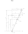
- FIG. 2 is a diagram describing how the position of the UV axis is controlled such that the wire tilt angle ⁇ does not change when the Z axis is moved while interrupting or continuing taper machining.
- the taper deviation vector is indicated by T in FIG. 2 . That is, the taper deviation vector T is defined as a vector whose start point is an intersecting point between the UV plane and the Z axis and whose end point is a machine coordinate position on the U axis and V axis, the UV plane being formed by the UV axis.
- the wire tilt angle ⁇ is defined as an angle formed at the position of the lower wire guide 112 by a line parallel to the Z axis and the wire electrode 4, the angle being a vertex angle of a triangle formed by three points: the position of an intersection point between a line passing through the lower wire guide 112 in parallel to the Z axis and the plane formed by the UV axis, the position of the end point of the taper deviation vector, and the position of the lower wire guide 112.
- the upper wire guide 111 is moved to a position indicated by 111a. In this case, the distance between upper and lower guides is L'.
- the taper deviation vector is indicated by T'.
- the upper wire guide 111 is moved to a position indicated by 111b. In this case, the distance between upper and lower guides is L".
- the taper deviation vector is indicated by T".
- the position of the upper wire guide 111 moves in the UV-axis direction in synchronization with the movement of the upper wire guide 111 in the Z-axis direction based on the taper deviation vector, making it possible to keep the tilt angle of the wire electrode 4, i.e., the wire tilt angle ⁇ , unchanged.
- FIGS. 3A and 3B are diagrams describing how it is possible to interrupt taper machining, move the Z axis by manual operation with the wire tilt angle maintained, and just proceed with machining. As shown in FIG. 3A , the workpiece 5 is machined along a machining path 6 by the wire electrode 4.
- Taper machining is interrupted at a position shown in FIG. 3A .
- the upper wire guide 111 With the wire tilt angle maintained, the upper wire guide 111 is moved manually upward along the Z axis.
- a core fall prevention jig 7 such as a magnet, i.e., for example, to carry out cutoff machining after attaching the jig to a core by manually raising the Z axis.
- machining can be carried out after the Z axis is moved with a wire tilt angle maintained while interrupting or continuing taper machining.
- FIG. 4 is a diagram describing how a workpiece whose plate thickness changes is taper-machined with high accuracy by moving up and down the Z axis by automatic operation.
- the workpiece 5 whose plate thickness changes can be taper-machined with high accuracy, by moving up and down the Z axis in synchronization with movement of the wire electrode 4 from left to right relative to the workpiece 5, by automatic operation.
- FIG. 5 is a diagram describing a process performed during manual operation. The process will be described below on a step by step basis.
- FIG. 6 is a diagram describing a process performed during automatic operation. The process will be described below on a step by step basis.
- the numerical control apparatus 120 adapted to control the wire electric discharge machine configured to be able to perform taper machining and described with reference to FIG. 1 is an example of "a wire electric discharge machining control apparatus for a wire electric discharge machine, including: an XY axis configured to move a workpiece in a horizontal direction relative to a wire; a UV axis configured to move one of upper and lower wire guides in the horizontal direction; and a Z axis configured to move one of the upper and lower wire guides in a vertical direction; and the wire electric discharge machining control apparatus configured to perform taper machining so that a wire tilt angle and a wire tilt direction match a specified wire tilt angle and a specified wire tilt direction" in claim 1.
- Step SA04 in the flowchart of FIG. 5 and step SB05 in the flowchart of FIG. 6 are examples of "a wire tilt angle calculation unit configured to calculate a wire tilt angle, when the Z axis is moved while interrupting or continuing taper machining, the wire tilt angle being the one existing before the Z axis is moved" in claim 1.
- Step SA06 in the flowchart of FIG. 5 and step SB04 in the flowchart of FIG. 6 are examples of "an upper and lower guides distance calculation unit configured to calculate a distance between upper and lower guides between the upper and lower wire guides from a machine coordinate position of the Z axis" in claim 1.
- Step SA07 in the flowchart of FIG. 5 and step SB06 in the flowchart of FIG. 6 are examples of "a taper deviation vector calculation unit configured to calculate a taper deviation vector based on the distance between upper and lower guides, the taper deviation vector being a horizontal deviation of the UV axis from the XY axis and defining a location at which the wire tilt angle calculated by the wire tilt angle calculation unit is maintained" in claim 1.
- Step SA09 in the flowchart of FIG. 5 and step SB08 in the flowchart of FIG. 6 are examples of "a UV axis position control unit configured to find a position at which the UV axis is spaced away from the XY axis by a distance defined by the taper deviation vector and thereby moving the UV axis" in claim 1.
- Claim 2 includes step SA04 in the flowchart of FIG. 5 , where step SA04 involves finding the taper deviation vector between the upper and lower wire guides from the machine coordinate position of the UV axis and finding the wire tilt angle from the taper deviation vector and the distance between upper and lower guides.
- Claim 3 includes step SB05 in the flowchart of FIG. 6 , where step SB05 involves using the wire tilt angle specified in the machining program when carrying out machining based on the machining program.
Abstract
Description
- The present invention relates to a numerical control apparatus for controlling a wire electric discharge machine which performs taper machining.
-
FIG. 7 is a diagram describing taper machining performed by a wire electric discharge machine. When taper machining is performed using a wire electric discharge machine, a distance between upper and lower guides L is set before the start of machining. The distance between upper and lower guides L is a vertical distance between alower wire guide 112 andupper wire guide 111. A taper deviation vector T of a UV axis is calculated from the distance between upper and lower guides L, a wire tilt angle command θ, and a wire tilt direction command θ and position of the UV axis is controlled such that the wire tilt angle and wire tilt direction conform to command values. - Japanese Patent Laid-Open No.
1-257525 -
FIG. 8 is a diagram describing an issue arising if the Z axis is moved while interrupting or continuing taper machining. If the Z axis is moved while interrupting or continuing taper machining, a discrepancy occurs between the distance between upper and lower guides L set before the start of machining and actual distance between upper and lower guides. Consequently, the wire tilt angle does not conform to the command. Therefore, if the Z axis is moved while interrupting or continuing taper machining, it is not possible to just proceed with the taper machining. - Thus, for example, on a taper machining block, it is not possible to carry out cutoff machining using a core fall prevention jig such as a magnet, i.e., carry out cutoff machining by manually raising the Z axis and mounting the jig. Also, a workpiece whose plate thickness changes cannot be taper-machined by moving up and down the Z axis.
- Japanese Patent Laid-Open No.
1-257525 - "It is determined whether the Z axis is moved automatically or manually (S1) if the Z axis is moved automatically and the T-U value (distance between the table surface and upper guide) of the electric discharge machine is stored in the memory of the NC (numerical calculation) device side(S2), taper data is calculated via T-U value calculation (S3)." (bottom line, upper left column, page 2);
- "On the other hand, if the Z axis is moved manually in S1, the height of the upper guide is entered manually (S21). Subsequent actions are similar to conventional ones" (
line 5, lower right column, page 2); and - The "T-U value calculation" and "taper data calculation" in S3 in
FIG. 1 are performed only when it is determined in S1 that the Z axis is moved automatically. - Also, no method is disclosed for controlling the position of the UV axis in such a way that the wire tilt angle does not change when the Z axis is moved in response to an automatic operation command during automatic operation, i.e., during taper machining.
- Thus, an object of the present invention is to provide a numerical control apparatus for controlling a wire electric discharge machine which performs taper machining, where the numerical control apparatus allows the wire electric discharge machine to just proceed with machining after the Z axis is moved with a wire tilt angle maintained while interrupting or continuing taper machining.
- For that, if the Z axis is moved while interrupting or continuing taper machining, the numerical control apparatus controls position of a UV axis by updating a distance between upper and lower guides and re-creating a taper deviation vector such that the wire tilt angle does not change.
- The present invention provides a wire electric discharge machining control apparatus for a wire electric discharge machine, including: an XY axis configured to move a workpiece in a horizontal direction relative to a wire, a UV axis configured to move one of upper and lower wire guides in the horizontal direction, and a Z axis configured to move one of the upper and lower wire guides in a vertical direction, and the wire electric discharge machining control apparatus is configured to perform taper machining so that a wire tilt angle and a wire tilt direction match a specified wire tilt angle and a specified wire tilt direction, the wire electric discharge machining control apparatus comprising: a wire tilt angle calculation unit configured to calculate a wire tilt angle, when the Z axis is moved while interrupting or continuing taper machining, the wire tilt angle being the one existing before the Z axis is moved; an upper and lower guides distance calculation unit configured to calculate a distance between upper and lower guides between the upper and lower wire guides, from a machine coordinate position of the Z axis; a taper deviation vector calculation unit configured to calculate a taper deviation vector based on the distance between upper and lower guides, the taper deviation vector being a horizontal deviation of the UV axis from the XY axis and defining a location at which the wire tilt angle calculated by the wire tilt angle calculation unit is maintained; and a UV axis position control unit configured to find a position at which the UV axis is spaced away from the XY axis by a distance defined by the taper deviation vector and thereby move the UV axis.
- The wire tilt angle calculation is further configured to find the taper deviation vector between the upper and lower wire guides from the machine coordinate position of the UV axis and find the wire tilt angle from the taper deviation vector and the distance between upper and lower guides.
- When machining is carried out based on a machining program, the wire tilt angle calculation unit may find the wire tilt angle based on the machining program.
- Being configured as described above, the present invention can provide a numerical control apparatus for controlling a wire electric discharge machine which performs taper machining, where the numerical control apparatus allows the wire electric discharge machine to just proceed with machining after the Z axis is moved with a wire tilt angle maintained while interrupting or continuing taper machining.
- The above and other objects and features of the present invention will become more apparent from the following description of the embodiments taken in conjunction with the accompanying drawings, wherein:
-
FIG. 1 is a diagram describing a configuration of a wire electric discharge machine; -
FIG. 2 is a diagram describing how position of a UV axis is controlled such that the wire tilt angle does not change when the Z axis is moved while interrupting or continuing taper machining; -
FIGS. 3A and 3B are diagrams describing how it is possible to interrupt taper machining, move the Z axis by manual operation with the wire tilt angle maintained, and just proceed with machining; -
FIG. 4 is a diagram describing how a workpiece whose plate thickness changes is taper-machined with high accuracy by moving up and down the Z axis by automatic operation; -
FIG. 5 is a diagram describing a process performed during manual operation; -
FIG. 6 is a diagram describing a process performed during automatic operation; -
FIG. 7 is a diagram describing taper machining performed by the wire electric discharge machine; and -
FIG. 8 is a diagram describing an issue arising if the Z axis is moved while interrupting or continuing taper machining. -
FIG. 1 is a diagram describing a configuration of a wire electric discharge machine.Reference numeral 101 denotes a workpiece holder on which aworkpiece 5 to be machined is mounted and fixed. Theworkpiece holder 101 has amounting surface 102 with precise flatness. During machining, theworkpiece 5 is mounted and fixed to theworkpiece holder 101 such that a bottom face of theworkpiece 5 is placed in contact with themounting surface 102. - To perform electric discharge machining of the
workpiece 5, awire electrode 4 is fed from a wire electrode delivery reel (not shown) to amachining zone 116 through afeed roller 115,upper guide roller 113, andupper wire guide 111. During machining, thewire electrode 4 is stretched between theupper wire guide 111 andlower wire guide 112 by manipulating a connection and a voltage is applied to produce electric discharges between thewire electrode 4 andworkpiece 5. - After passing through the
machining zone 116 and further through thelower wire guide 112 and alower guide roller 114, thewire electrode 4 is wound up by a take-up reel (not shown) adapted to pull thewire electrode 4 with a predetermined tensile force. Note that thewire electrode 4 may be recovered in a wire recovery box (not shown) instead of the take-up reel. - Electric energy for electric discharge machining is supplied to the
wire electrode 4 from amachining power supply 121 via thefeed roller 115 according to apulse train 117 outputted from anumerical control apparatus 120. For the purpose of control, the number of pulses or value of an integral of a pulse current inputted from themachining power supply 121 can be treated as an amount of the energy. Also, cooling water is poured over themachining zone 116 or another technique is adopted such as immersing theentire workpiece 5 in a working fluid such as pure water, for example. - Most commonly, the
mounting surface 102 of theworkpiece holder 101 extends in a horizontal direction, i.e., on a plane parallel to an XY plane and theworkpiece holder 101 is configured to be drivable by X-axis and Y-axis servomotors upper wire guide 111 is configured to be drivable by U-axis and V-axis servomotors axis servomotor 110 in a direction perpendicular to the XY plane, i.e., in a ± Z direction. Most commonly, a moving direction along the U axis and moving direction along the X axis are parallel to each other and a moving direction along the V axis and moving direction along the Y axis are parallel to each other. Note that current positions of respective drive shafts, i.e., the X axis, Y axis, Z axis, U axis, and V axis are stored as machine coordinate positions in a storage device of thenumerical control apparatus 120. Machine coordinate position of thelower wire guide 112 is stored in advance as a parameter in the storage device of thenumerical control apparatus 120. - The
machining zone 116 can be change by changing relative position of theworkpiece 5 andwire electrode 4, and themachining zone 116 is changed by commands for the servomotors of respective axes, i.e., an X-axis command, Y-axis command, Z-axis command, U-axis command, and V-axis command, outputted from thenumerical control apparatus 120. Most commonly, details of the commands are prescribed by a machining program. The machining program prescribes move commands for thewire electrode 4, i.e., move commands for the servomotors of respective axes, and is defined on a plane parallel to the XY plane described above. The plane on which the machining program is defined can be set at an arbitrary position in a Z-axis direction. The plane set arbitrarily is referred to as a programming plane. - According to one embodiment of the present invention, in the wire electric discharge machine described above, when the Z axis is moved while interrupting or continuing taper machining, the position of a UV axis is controlled by updating the distance between upper and lower guides L according to the movement and re-creating the taper deviation vector such that the wire tilt angle θ does not change.
- Now the taper deviation vector will be described with reference to
FIG. 2 . InFIG. 2 , a direction perpendicular to the plane formed by the XY axis is designated as the Z-axis direction.FIG. 2 is a diagram describing how the position of the UV axis is controlled such that the wire tilt angle θ does not change when the Z axis is moved while interrupting or continuing taper machining. - When the upper wire guide is located at a position indicated by 111, the distance between upper and lower guides in the Z-axis direction is L. In this case, the taper deviation vector is indicated by T in
FIG. 2 . That is, the taper deviation vector T is defined as a vector whose start point is an intersecting point between the UV plane and the Z axis and whose end point is a machine coordinate position on the U axis and V axis, the UV plane being formed by the UV axis. Also, the wire tilt angle θ is defined as an angle formed at the position of thelower wire guide 112 by a line parallel to the Z axis and thewire electrode 4, the angle being a vertex angle of a triangle formed by three points: the position of an intersection point between a line passing through thelower wire guide 112 in parallel to the Z axis and the plane formed by the UV axis, the position of the end point of the taper deviation vector, and the position of thelower wire guide 112. - The
upper wire guide 111 is moved to a position indicated by 111a. In this case, the distance between upper and lower guides is L'. The taper deviation vector is indicated by T'. Also, theupper wire guide 111 is moved to a position indicated by 111b. In this case, the distance between upper and lower guides is L". The taper deviation vector is indicated by T". As shown inFIG. 2 , the position of theupper wire guide 111 moves in the UV-axis direction in synchronization with the movement of theupper wire guide 111 in the Z-axis direction based on the taper deviation vector, making it possible to keep the tilt angle of thewire electrode 4, i.e., the wire tilt angle θ, unchanged. -
FIGS. 3A and 3B are diagrams describing how it is possible to interrupt taper machining, move the Z axis by manual operation with the wire tilt angle maintained, and just proceed with machining. As shown inFIG. 3A , theworkpiece 5 is machined along amachining path 6 by thewire electrode 4. - Taper machining is interrupted at a position shown in
FIG. 3A . - With the wire tilt angle maintained, the
upper wire guide 111 is moved manually upward along the Z axis. This, makes it possible, as shown inFIG. 3B , to carry out cutoff machining on a taper machining block using a corefall prevention jig 7 such as a magnet, i.e., for example, to carry out cutoff machining after attaching the jig to a core by manually raising the Z axis. In this way, machining can be carried out after the Z axis is moved with a wire tilt angle maintained while interrupting or continuing taper machining. -
FIG. 4 is a diagram describing how a workpiece whose plate thickness changes is taper-machined with high accuracy by moving up and down the Z axis by automatic operation. Theworkpiece 5 whose plate thickness changes can be taper-machined with high accuracy, by moving up and down the Z axis in synchronization with movement of thewire electrode 4 from left to right relative to theworkpiece 5, by automatic operation. -
FIG. 5 is a diagram describing a process performed during manual operation. The process will be described below on a step by step basis. - [Step SA01] It is determined whether or not there is any manual axial movement command. If there is an axial movement command (YES), the flow goes to step SA02, and if there is no axial movement command (NO), the processing is finished.
- [Step SA02] It is determined whether or not the axial movement concerns the Z axis. If the axial movement concerns the Z axis (YES), the flow goes to step SA03, and if the axial movement does not concern the Z axis (NO), the flow goes to step SA09.
- [Step SA03] It is determined whether or not automatic operation is suspended or stopped. If automatic operation is suspended or stopped (YES), the flow goes to step SA04, and if automatic operation is not suspended or stopped (NO), the flow goes to step SA09.
- [Step SA04] The wire tilt angle is calculated.
- [Step SA05] It is determined whether or not the
wire electrode 4 is tilted. If thewire electrode 4 is tilted (YES), the flow goes to step SA06, and if thewire electrode 4 is not tilted (NO), the flow goes to step SA09. - [Step SA06] The distance between the upper and lower wire guides is updated.
- [Step SA07] A UV-axis deviation vector for use to maintain the tilt angle of the
wire electrode 4 is calculated. - [Step SA08] An amount of movement on the UV axis is calculated.
- [Step SA09] The axial movement is performed and the processing is finished.
-
FIG. 6 is a diagram describing a process performed during automatic operation. The process will be described below on a step by step basis. - [Step SB01] The distance between the upper and lower wire guides is set. That is, the distance between the upper and lower wire guides prestored as a parameter in the control apparatus is read out.
- [Step SB02] One block is read out.
- [Step SB03] It is determined whether or not the command in the block read in step SB02 is a Z-axis command. If the command is a Z-axis command (YES), the flow goes to step SB04, and if the command is not a Z-axis command (NO), the flow goes to step SB05.
- [Step SB04] The distance between the upper and lower wire guides at the end point of the block is updated.
- [Step SB05] It is determined whether or not the command in the one block read in step SB02 is a wire electrode tilt command. If the command is a wire electrode tilt command (YES), the flow goes to step SB06, and if the command is not a wire electrode tilt command (NO), the flow goes to step SB08.
- [Step SB06] The UV-axis deviation vector at the end point of the block read in step SB02 is calculated.
- [Step SB07] The amount of movement on the UV axis is calculated.
- [Step SB08] Block execution data is calculated, a calculation result is outputted to an execution task, and the flow goes to step SB09.
- [Step SB09] It is determined whether or not the program has reached its end. If the program has reached its end (YES), the processing is finished, and if the program has not reached its end yet (NO), the flow returns to step SB02.
- Note that the
numerical control apparatus 120 adapted to control the wire electric discharge machine configured to be able to perform taper machining and described with reference toFIG. 1 is an example of "a wire electric discharge machining control apparatus for a wire electric discharge machine, including: an XY axis configured to move a workpiece in a horizontal direction relative to a wire; a UV axis configured to move one of upper and lower wire guides in the horizontal direction; and a Z axis configured to move one of the upper and lower wire guides in a vertical direction; and the wire electric discharge machining control apparatus configured to perform taper machining so that a wire tilt angle and a wire tilt direction match a specified wire tilt angle and a specified wire tilt direction" in claim 1. - Step SA04 in the flowchart of
FIG. 5 and step SB05 in the flowchart ofFIG. 6 are examples of "a wire tilt angle calculation unit configured to calculate a wire tilt angle, when the Z axis is moved while interrupting or continuing taper machining, the wire tilt angle being the one existing before the Z axis is moved" in claim 1. - Step SA06 in the flowchart of
FIG. 5 and step SB04 in the flowchart ofFIG. 6 are examples of "an upper and lower guides distance calculation unit configured to calculate a distance between upper and lower guides between the upper and lower wire guides from a machine coordinate position of the Z axis" in claim 1. - Step SA07 in the flowchart of
FIG. 5 and step SB06 in the flowchart ofFIG. 6 are examples of "a taper deviation vector calculation unit configured to calculate a taper deviation vector based on the distance between upper and lower guides, the taper deviation vector being a horizontal deviation of the UV axis from the XY axis and defining a location at which the wire tilt angle calculated by the wire tilt angle calculation unit is maintained" in claim 1. - Step SA09 in the flowchart of
FIG. 5 and step SB08 in the flowchart ofFIG. 6 are examples of "a UV axis position control unit configured to find a position at which the UV axis is spaced away from the XY axis by a distance defined by the taper deviation vector and thereby moving the UV axis" in claim 1. - Claim 2 includes step SA04 in the flowchart of
FIG. 5 , where step SA04 involves finding the taper deviation vector between the upper and lower wire guides from the machine coordinate position of the UV axis and finding the wire tilt angle from the taper deviation vector and the distance between upper and lower guides. - Claim 3 includes step SB05 in the flowchart of
FIG. 6 , where step SB05 involves using the wire tilt angle specified in the machining program when carrying out machining based on the machining program.
Claims (3)
- A wire electric discharge machining control apparatus for a wire electric discharge machine, including:an XY axis configured to move a workpiece in a horizontal direction relative to a wire;a UV axis configured to move one of upper and lower wire guides in the horizontal direction; anda Z axis configured to move one of the upper and lower wire guides in a vertical direction; and configured to perform taper machining so that a wire tilt angle and a wire tilt direction match a specified wire tilt angle and a specified wire tilt direction, the wire electric discharge machining control apparatus comprising:a wire tilt angle calculation unit configured to calculate a wire tilt angle, when the Z axis is moved while interrupting or continuing taper machining, the wire tilt angle being the one existing before the Z axis is moved;an upper and lower guides distance calculation unit configured to calculate a distance between the upper and lower wire guides, from a machine coordinate position of the Z axis;a taper deviation vector calculation unit configured to calculate a taper deviation vector based on the distance between upper and lower guides, the taper deviation vector being a horizontal deviation of the UV axis from the XY axis and defining a location at which the wire tilt angle calculated by the wire tilt angle calculation unit is maintained; anda UV axis position control unit configured to find a position at which the UV axis is spaced away from the XY axis by a distance defined by the taper deviation vector and move the UV axis.
- The wire electric discharge machining control apparatus according to claim 1, the wire tilt angle calculation unit is further configured to find the taper deviation vector between the upper and lower wire guides from the machine coordinate position of the UV axis and find the wire tilt angle from the taper deviation vector and the distance between upper and lower guides.
- The wire electric discharge machining control apparatus according to claim 1, the wire tilt angle calculation unit is further configured to find the wire tilt angle based on a machining program when machining is carried out based on the machining program.
Applications Claiming Priority (1)
| Application Number | Priority Date | Filing Date | Title |
|---|---|---|---|
| JP2013186726A JP5850894B2 (en) | 2013-09-09 | 2013-09-09 | Numerical control device for controlling wire electric discharge machine that performs taper machining |
Publications (3)
| Publication Number | Publication Date |
|---|---|
| EP2845677A2 true EP2845677A2 (en) | 2015-03-11 |
| EP2845677A3 EP2845677A3 (en) | 2015-05-20 |
| EP2845677B1 EP2845677B1 (en) | 2018-09-19 |
Family
ID=51392137
Family Applications (1)
| Application Number | Title | Priority Date | Filing Date |
|---|---|---|---|
| EP14182201.5A Active EP2845677B1 (en) | 2013-09-09 | 2014-08-26 | Numerical control apparatus for controlling wire electric discharge machine which performs taper machining |
Country Status (4)
| Country | Link |
|---|---|
| US (1) | US9649709B2 (en) |
| EP (1) | EP2845677B1 (en) |
| JP (1) | JP5850894B2 (en) |
| CN (1) | CN104416246B (en) |
Cited By (1)
| Publication number | Priority date | Publication date | Assignee | Title |
|---|---|---|---|---|
| CN110961735A (en) * | 2018-09-28 | 2020-04-07 | 富泰华工业(深圳)有限公司 | Plane correction method for wire cutting machining and wire cutting machine |
Families Citing this family (4)
| Publication number | Priority date | Publication date | Assignee | Title |
|---|---|---|---|---|
| JP6480894B2 (en) * | 2016-07-25 | 2019-03-13 | ファナック株式会社 | Wire electric discharge machine and wire electric discharge machining method |
| CN112077403B (en) * | 2020-09-10 | 2021-12-24 | 力同机械自动化(上海)有限公司 | Perpendicularity adjusting method for taper head |
| CN114226895B (en) * | 2021-12-15 | 2023-04-18 | 江苏源清动力技术有限公司 | High-precision small hole machining method |
| CN116140728A (en) * | 2023-03-25 | 2023-05-23 | 江苏华力精密机械有限公司 | Guiding device for numerical control linear cutting machine |
Citations (1)
| Publication number | Priority date | Publication date | Assignee | Title |
|---|---|---|---|---|
| JPH01257525A (en) | 1988-04-08 | 1989-10-13 | Sodick Co Ltd | Wire cut electric discharge machining |
Family Cites Families (13)
| Publication number | Priority date | Publication date | Assignee | Title |
|---|---|---|---|---|
| JPS56102433A (en) * | 1980-01-19 | 1981-08-15 | Mitsubishi Electric Corp | Wire cut discharge machining method |
| US4460816A (en) * | 1982-07-06 | 1984-07-17 | Ateliers Des Charmilles, S.A. | Apparatus for orienting the wire electrode support and guide member and the machining fluid nozzle of a travelling wire EDM apparatus |
| CH670590A5 (en) * | 1987-04-03 | 1989-06-30 | Charmilles Technologies | |
| DE3810662A1 (en) * | 1988-03-29 | 1989-10-19 | Agie Ag Ind Elektronik | METHOD AND DEVICE FOR NUMERICAL TRAIN CONTROL FOR ELECTROERODING MACHINES |
| JP2734145B2 (en) * | 1989-12-15 | 1998-03-30 | 三菱電機株式会社 | Wire electric discharge machine |
| JP3552753B2 (en) * | 1994-08-08 | 2004-08-11 | ファナック株式会社 | Wire squareness control method |
| JP2000235408A (en) * | 1999-02-17 | 2000-08-29 | Sodick Co Ltd | Method and device for checking nc program in taper cut of wirecut electric discharge machining |
| JP2002018647A (en) * | 2000-06-30 | 2002-01-22 | Brother Ind Ltd | Device and method for controlling wire electric discharge machine and storage medium |
| JP2004142027A (en) * | 2002-10-24 | 2004-05-20 | Fanuc Ltd | Wire electric discharge machine |
| JP2005153128A (en) * | 2003-11-28 | 2005-06-16 | Fanuc Ltd | Hand feed device in wire electric discharge machine |
| CN1775442A (en) * | 2004-11-15 | 2006-05-24 | 发那科株式会社 | Electric spark linear cutting machine and machining method thereof |
| JP2006159396A (en) * | 2004-11-15 | 2006-06-22 | Fanuc Ltd | Wire electric discharge machine and wire electric discharge machining method |
| JP4072548B2 (en) * | 2005-09-26 | 2008-04-09 | ファナック株式会社 | Wire electric discharge machine |
-
2013
- 2013-09-09 JP JP2013186726A patent/JP5850894B2/en active Active
-
2014
- 2014-08-26 EP EP14182201.5A patent/EP2845677B1/en active Active
- 2014-08-28 US US14/471,455 patent/US9649709B2/en active Active
- 2014-09-05 CN CN201410454077.6A patent/CN104416246B/en active Active
Patent Citations (1)
| Publication number | Priority date | Publication date | Assignee | Title |
|---|---|---|---|---|
| JPH01257525A (en) | 1988-04-08 | 1989-10-13 | Sodick Co Ltd | Wire cut electric discharge machining |
Cited By (1)
| Publication number | Priority date | Publication date | Assignee | Title |
|---|---|---|---|---|
| CN110961735A (en) * | 2018-09-28 | 2020-04-07 | 富泰华工业(深圳)有限公司 | Plane correction method for wire cutting machining and wire cutting machine |
Also Published As
| Publication number | Publication date |
|---|---|
| CN104416246B (en) | 2018-01-30 |
| EP2845677A3 (en) | 2015-05-20 |
| US9649709B2 (en) | 2017-05-16 |
| EP2845677B1 (en) | 2018-09-19 |
| JP2015051492A (en) | 2015-03-19 |
| US20150069022A1 (en) | 2015-03-12 |
| CN104416246A (en) | 2015-03-18 |
| JP5850894B2 (en) | 2016-02-03 |
Similar Documents
| Publication | Publication Date | Title |
|---|---|---|
| EP2845677B1 (en) | Numerical control apparatus for controlling wire electric discharge machine which performs taper machining | |
| JP5108132B1 (en) | Wire electric discharge machine that performs taper machining by tilting the workpiece | |
| JP5369205B2 (en) | Wire electric discharge machine and wire electric discharge machining method for reducing machining flaws at the time of cutting and escaping | |
| EP2495063B1 (en) | Wire-cut electric discharge machine having function of detecting upper surface of workpiece | |
| EP2959998B1 (en) | Machining program creating device for keyway machining for wire electric discharge machine | |
| EP2626161A2 (en) | Wire electric discharge machine performing turning tool machining, turning tool machining method with wire electric discharge machine, and program creation apparatus for wire electric discharge machine that performs turning tool machining | |
| EP2617506B1 (en) | Wire electrical discharge machine carrying out electrical discharge machining by inclining wire electrode | |
| KR101980416B1 (en) | Wire electric discharge machine having function of moving from arbitrary retreat position in electric discharge state and returning to halt position | |
| EP2295180B1 (en) | Wire electric discharge machining method, apparatus therefor, wire electric discharge machining program creating device, and computer-readable recording medium in which program for creating wire electric discharge machining program is stored | |
| KR101999920B1 (en) | Wire electrical discharge machine and control method for wire electrical discharge machine | |
| JP5731613B2 (en) | Wire electric discharge machine and control device for wire electric discharge machine | |
| EP2783781A2 (en) | Wire electric discharge machine with automatic wire connecting function | |
| JP2014241074A (en) | Numerical value control device having function for smoothly changing feeding speed when overriding changes | |
| JP4569973B2 (en) | Electric discharge machining apparatus and method, and method for determining occurrence of electric discharge | |
| JP5908552B1 (en) | Machine tool controller | |
| JP5877915B2 (en) | Numerical control device for controlling machine tools | |
| EP3139232A1 (en) | Machining program creation apparatus for wire electrical discharge machiine | |
| JP6267161B2 (en) | Numerical control device that controls two parallel axes | |
| JPH0542415A (en) | Electric discharge machining method |
Legal Events
| Date | Code | Title | Description |
|---|---|---|---|
| 17P | Request for examination filed |
Effective date: 20140826 |
|
| AK | Designated contracting states |
Kind code of ref document: A2 Designated state(s): AL AT BE BG CH CY CZ DE DK EE ES FI FR GB GR HR HU IE IS IT LI LT LU LV MC MK MT NL NO PL PT RO RS SE SI SK SM TR |
|
| AX | Request for extension of the european patent |
Extension state: BA ME |
|
| PUAI | Public reference made under article 153(3) epc to a published international application that has entered the european phase |
Free format text: ORIGINAL CODE: 0009012 |
|
| PUAL | Search report despatched |
Free format text: ORIGINAL CODE: 0009013 |
|
| AK | Designated contracting states |
Kind code of ref document: A3 Designated state(s): AL AT BE BG CH CY CZ DE DK EE ES FI FR GB GR HR HU IE IS IT LI LT LU LV MC MK MT NL NO PL PT RO RS SE SI SK SM TR |
|
| AX | Request for extension of the european patent |
Extension state: BA ME |
|
| RIC1 | Information provided on ipc code assigned before grant |
Ipc: B23H 7/06 20060101AFI20150410BHEP |
|
| R17P | Request for examination filed (corrected) |
Effective date: 20151117 |
|
| RBV | Designated contracting states (corrected) |
Designated state(s): AL AT BE BG CH CY CZ DE DK EE ES FI FR GB GR HR HU IE IS IT LI LT LU LV MC MK MT NL NO PL PT RO RS SE SI SK SM TR |
|
| STAA | Information on the status of an ep patent application or granted ep patent |
Free format text: STATUS: EXAMINATION IS IN PROGRESS |
|
| 17Q | First examination report despatched |
Effective date: 20170502 |
|
| GRAP | Despatch of communication of intention to grant a patent |
Free format text: ORIGINAL CODE: EPIDOSNIGR1 |
|
| STAA | Information on the status of an ep patent application or granted ep patent |
Free format text: STATUS: GRANT OF PATENT IS INTENDED |
|
| INTG | Intention to grant announced |
Effective date: 20180409 |
|
| GRAS | Grant fee paid |
Free format text: ORIGINAL CODE: EPIDOSNIGR3 |
|
| GRAA | (expected) grant |
Free format text: ORIGINAL CODE: 0009210 |
|
| STAA | Information on the status of an ep patent application or granted ep patent |
Free format text: STATUS: THE PATENT HAS BEEN GRANTED |
|
| AK | Designated contracting states |
Kind code of ref document: B1 Designated state(s): AL AT BE BG CH CY CZ DE DK EE ES FI FR GB GR HR HU IE IS IT LI LT LU LV MC MK MT NL NO PL PT RO RS SE SI SK SM TR |
|
| REG | Reference to a national code |
Ref country code: GB Ref legal event code: FG4D |
|
| REG | Reference to a national code |
Ref country code: CH Ref legal event code: EP |
|
| REG | Reference to a national code |
Ref country code: AT Ref legal event code: REF Ref document number: 1042669 Country of ref document: AT Kind code of ref document: T Effective date: 20181015 |
|
| REG | Reference to a national code |
Ref country code: IE Ref legal event code: FG4D |
|
| REG | Reference to a national code |
Ref country code: DE Ref legal event code: R096 Ref document number: 602014032437 Country of ref document: DE |
|
| REG | Reference to a national code |
Ref country code: NL Ref legal event code: MP Effective date: 20180919 |
|
| PG25 | Lapsed in a contracting state [announced via postgrant information from national office to epo] |
Ref country code: BG Free format text: LAPSE BECAUSE OF FAILURE TO SUBMIT A TRANSLATION OF THE DESCRIPTION OR TO PAY THE FEE WITHIN THE PRESCRIBED TIME-LIMIT Effective date: 20181219 Ref country code: RS Free format text: LAPSE BECAUSE OF FAILURE TO SUBMIT A TRANSLATION OF THE DESCRIPTION OR TO PAY THE FEE WITHIN THE PRESCRIBED TIME-LIMIT Effective date: 20180919 Ref country code: NO Free format text: LAPSE BECAUSE OF FAILURE TO SUBMIT A TRANSLATION OF THE DESCRIPTION OR TO PAY THE FEE WITHIN THE PRESCRIBED TIME-LIMIT Effective date: 20181219 Ref country code: GR Free format text: LAPSE BECAUSE OF FAILURE TO SUBMIT A TRANSLATION OF THE DESCRIPTION OR TO PAY THE FEE WITHIN THE PRESCRIBED TIME-LIMIT Effective date: 20181220 Ref country code: LT Free format text: LAPSE BECAUSE OF FAILURE TO SUBMIT A TRANSLATION OF THE DESCRIPTION OR TO PAY THE FEE WITHIN THE PRESCRIBED TIME-LIMIT Effective date: 20180919 Ref country code: FI Free format text: LAPSE BECAUSE OF FAILURE TO SUBMIT A TRANSLATION OF THE DESCRIPTION OR TO PAY THE FEE WITHIN THE PRESCRIBED TIME-LIMIT Effective date: 20180919 Ref country code: SE Free format text: LAPSE BECAUSE OF FAILURE TO SUBMIT A TRANSLATION OF THE DESCRIPTION OR TO PAY THE FEE WITHIN THE PRESCRIBED TIME-LIMIT Effective date: 20180919 |
|
| REG | Reference to a national code |
Ref country code: LT Ref legal event code: MG4D |
|
| PG25 | Lapsed in a contracting state [announced via postgrant information from national office to epo] |
Ref country code: AL Free format text: LAPSE BECAUSE OF FAILURE TO SUBMIT A TRANSLATION OF THE DESCRIPTION OR TO PAY THE FEE WITHIN THE PRESCRIBED TIME-LIMIT Effective date: 20180919 Ref country code: LV Free format text: LAPSE BECAUSE OF FAILURE TO SUBMIT A TRANSLATION OF THE DESCRIPTION OR TO PAY THE FEE WITHIN THE PRESCRIBED TIME-LIMIT Effective date: 20180919 Ref country code: HR Free format text: LAPSE BECAUSE OF FAILURE TO SUBMIT A TRANSLATION OF THE DESCRIPTION OR TO PAY THE FEE WITHIN THE PRESCRIBED TIME-LIMIT Effective date: 20180919 |
|
| REG | Reference to a national code |
Ref country code: AT Ref legal event code: MK05 Ref document number: 1042669 Country of ref document: AT Kind code of ref document: T Effective date: 20180919 |
|
| PG25 | Lapsed in a contracting state [announced via postgrant information from national office to epo] |
Ref country code: EE Free format text: LAPSE BECAUSE OF FAILURE TO SUBMIT A TRANSLATION OF THE DESCRIPTION OR TO PAY THE FEE WITHIN THE PRESCRIBED TIME-LIMIT Effective date: 20180919 Ref country code: PL Free format text: LAPSE BECAUSE OF FAILURE TO SUBMIT A TRANSLATION OF THE DESCRIPTION OR TO PAY THE FEE WITHIN THE PRESCRIBED TIME-LIMIT Effective date: 20180919 Ref country code: IS Free format text: LAPSE BECAUSE OF FAILURE TO SUBMIT A TRANSLATION OF THE DESCRIPTION OR TO PAY THE FEE WITHIN THE PRESCRIBED TIME-LIMIT Effective date: 20190119 Ref country code: CZ Free format text: LAPSE BECAUSE OF FAILURE TO SUBMIT A TRANSLATION OF THE DESCRIPTION OR TO PAY THE FEE WITHIN THE PRESCRIBED TIME-LIMIT Effective date: 20180919 Ref country code: ES Free format text: LAPSE BECAUSE OF FAILURE TO SUBMIT A TRANSLATION OF THE DESCRIPTION OR TO PAY THE FEE WITHIN THE PRESCRIBED TIME-LIMIT Effective date: 20180919 Ref country code: NL Free format text: LAPSE BECAUSE OF FAILURE TO SUBMIT A TRANSLATION OF THE DESCRIPTION OR TO PAY THE FEE WITHIN THE PRESCRIBED TIME-LIMIT Effective date: 20180919 Ref country code: IT Free format text: LAPSE BECAUSE OF FAILURE TO SUBMIT A TRANSLATION OF THE DESCRIPTION OR TO PAY THE FEE WITHIN THE PRESCRIBED TIME-LIMIT Effective date: 20180919 Ref country code: RO Free format text: LAPSE BECAUSE OF FAILURE TO SUBMIT A TRANSLATION OF THE DESCRIPTION OR TO PAY THE FEE WITHIN THE PRESCRIBED TIME-LIMIT Effective date: 20180919 Ref country code: AT Free format text: LAPSE BECAUSE OF FAILURE TO SUBMIT A TRANSLATION OF THE DESCRIPTION OR TO PAY THE FEE WITHIN THE PRESCRIBED TIME-LIMIT Effective date: 20180919 |
|
| PG25 | Lapsed in a contracting state [announced via postgrant information from national office to epo] |
Ref country code: SK Free format text: LAPSE BECAUSE OF FAILURE TO SUBMIT A TRANSLATION OF THE DESCRIPTION OR TO PAY THE FEE WITHIN THE PRESCRIBED TIME-LIMIT Effective date: 20180919 Ref country code: SM Free format text: LAPSE BECAUSE OF FAILURE TO SUBMIT A TRANSLATION OF THE DESCRIPTION OR TO PAY THE FEE WITHIN THE PRESCRIBED TIME-LIMIT Effective date: 20180919 Ref country code: PT Free format text: LAPSE BECAUSE OF FAILURE TO SUBMIT A TRANSLATION OF THE DESCRIPTION OR TO PAY THE FEE WITHIN THE PRESCRIBED TIME-LIMIT Effective date: 20190119 |
|
| REG | Reference to a national code |
Ref country code: DE Ref legal event code: R097 Ref document number: 602014032437 Country of ref document: DE |
|
| PLBE | No opposition filed within time limit |
Free format text: ORIGINAL CODE: 0009261 |
|
| STAA | Information on the status of an ep patent application or granted ep patent |
Free format text: STATUS: NO OPPOSITION FILED WITHIN TIME LIMIT |
|
| PG25 | Lapsed in a contracting state [announced via postgrant information from national office to epo] |
Ref country code: DK Free format text: LAPSE BECAUSE OF FAILURE TO SUBMIT A TRANSLATION OF THE DESCRIPTION OR TO PAY THE FEE WITHIN THE PRESCRIBED TIME-LIMIT Effective date: 20180919 |
|
| 26N | No opposition filed |
Effective date: 20190620 |
|
| PG25 | Lapsed in a contracting state [announced via postgrant information from national office to epo] |
Ref country code: SI Free format text: LAPSE BECAUSE OF FAILURE TO SUBMIT A TRANSLATION OF THE DESCRIPTION OR TO PAY THE FEE WITHIN THE PRESCRIBED TIME-LIMIT Effective date: 20180919 |
|
| PG25 | Lapsed in a contracting state [announced via postgrant information from national office to epo] |
Ref country code: TR Free format text: LAPSE BECAUSE OF FAILURE TO SUBMIT A TRANSLATION OF THE DESCRIPTION OR TO PAY THE FEE WITHIN THE PRESCRIBED TIME-LIMIT Effective date: 20180919 |
|
| GBPC | Gb: european patent ceased through non-payment of renewal fee |
Effective date: 20190826 |
|
| PG25 | Lapsed in a contracting state [announced via postgrant information from national office to epo] |
Ref country code: MC Free format text: LAPSE BECAUSE OF FAILURE TO SUBMIT A TRANSLATION OF THE DESCRIPTION OR TO PAY THE FEE WITHIN THE PRESCRIBED TIME-LIMIT Effective date: 20180919 Ref country code: LU Free format text: LAPSE BECAUSE OF NON-PAYMENT OF DUE FEES Effective date: 20190826 |
|
| REG | Reference to a national code |
Ref country code: BE Ref legal event code: MM Effective date: 20190831 |
|
| PG25 | Lapsed in a contracting state [announced via postgrant information from national office to epo] |
Ref country code: IE Free format text: LAPSE BECAUSE OF NON-PAYMENT OF DUE FEES Effective date: 20190826 Ref country code: FR Free format text: LAPSE BECAUSE OF NON-PAYMENT OF DUE FEES Effective date: 20190831 |
|
| PG25 | Lapsed in a contracting state [announced via postgrant information from national office to epo] |
Ref country code: BE Free format text: LAPSE BECAUSE OF NON-PAYMENT OF DUE FEES Effective date: 20190831 Ref country code: GB Free format text: LAPSE BECAUSE OF NON-PAYMENT OF DUE FEES Effective date: 20190826 |
|
| REG | Reference to a national code |
Ref country code: DE Ref legal event code: R082 Ref document number: 602014032437 Country of ref document: DE Representative=s name: HL KEMPNER PATENTANWAELTE, SOLICITORS (ENGLAND, DE Ref country code: DE Ref legal event code: R082 Ref document number: 602014032437 Country of ref document: DE Representative=s name: HL KEMPNER PATENTANWALT, RECHTSANWALT, SOLICIT, DE |
|
| PG25 | Lapsed in a contracting state [announced via postgrant information from national office to epo] |
Ref country code: CY Free format text: LAPSE BECAUSE OF FAILURE TO SUBMIT A TRANSLATION OF THE DESCRIPTION OR TO PAY THE FEE WITHIN THE PRESCRIBED TIME-LIMIT Effective date: 20180919 |
|
| PG25 | Lapsed in a contracting state [announced via postgrant information from national office to epo] |
Ref country code: MT Free format text: LAPSE BECAUSE OF FAILURE TO SUBMIT A TRANSLATION OF THE DESCRIPTION OR TO PAY THE FEE WITHIN THE PRESCRIBED TIME-LIMIT Effective date: 20180919 Ref country code: HU Free format text: LAPSE BECAUSE OF FAILURE TO SUBMIT A TRANSLATION OF THE DESCRIPTION OR TO PAY THE FEE WITHIN THE PRESCRIBED TIME-LIMIT; INVALID AB INITIO Effective date: 20140826 |
|
| PG25 | Lapsed in a contracting state [announced via postgrant information from national office to epo] |
Ref country code: MK Free format text: LAPSE BECAUSE OF FAILURE TO SUBMIT A TRANSLATION OF THE DESCRIPTION OR TO PAY THE FEE WITHIN THE PRESCRIBED TIME-LIMIT Effective date: 20180919 |
|
| PGFP | Annual fee paid to national office [announced via postgrant information from national office to epo] |
Ref country code: CH Payment date: 20230902 Year of fee payment: 10 |
|
| PGFP | Annual fee paid to national office [announced via postgrant information from national office to epo] |
Ref country code: DE Payment date: 20230703 Year of fee payment: 10 |