EP3023068A2 - Bone plates, plate alignment systems, and methods of use - Google Patents
Bone plates, plate alignment systems, and methods of use Download PDFInfo
- Publication number
- EP3023068A2 EP3023068A2 EP15195121.7A EP15195121A EP3023068A2 EP 3023068 A2 EP3023068 A2 EP 3023068A2 EP 15195121 A EP15195121 A EP 15195121A EP 3023068 A2 EP3023068 A2 EP 3023068A2
- Authority
- EP
- European Patent Office
- Prior art keywords
- bone plate
- curvature
- plate
- bone
- lobe
- Prior art date
- Legal status (The legal status is an assumption and is not a legal conclusion. Google has not performed a legal analysis and makes no representation as to the accuracy of the status listed.)
- Granted
Links
- 210000000988 bone and bone Anatomy 0.000 title claims abstract description 146
- 238000000034 method Methods 0.000 title abstract description 28
- 238000003780 insertion Methods 0.000 claims abstract description 21
- 230000037431 insertion Effects 0.000 claims abstract description 21
- 230000008878 coupling Effects 0.000 claims description 11
- 238000010168 coupling process Methods 0.000 claims description 11
- 238000005859 coupling reaction Methods 0.000 claims description 11
- 230000001012 protector Effects 0.000 claims description 7
- 230000007704 transition Effects 0.000 description 30
- 210000002683 foot Anatomy 0.000 description 8
- 210000002435 tendon Anatomy 0.000 description 7
- 230000009977 dual effect Effects 0.000 description 6
- 210000001872 metatarsal bone Anatomy 0.000 description 5
- 210000001519 tissue Anatomy 0.000 description 5
- 238000012937 correction Methods 0.000 description 4
- 240000007817 Olea europaea Species 0.000 description 3
- 230000006835 compression Effects 0.000 description 3
- 238000007906 compression Methods 0.000 description 3
- 239000007943 implant Substances 0.000 description 3
- 238000001356 surgical procedure Methods 0.000 description 3
- 230000004075 alteration Effects 0.000 description 2
- 230000008859 change Effects 0.000 description 2
- 230000005021 gait Effects 0.000 description 2
- 230000007794 irritation Effects 0.000 description 2
- 238000012986 modification Methods 0.000 description 2
- 230000004048 modification Effects 0.000 description 2
- 230000000399 orthopedic effect Effects 0.000 description 2
- 210000004872 soft tissue Anatomy 0.000 description 2
- 238000013519 translation Methods 0.000 description 2
- 206010061159 Foot deformity Diseases 0.000 description 1
- 208000001963 Hallux Valgus Diseases 0.000 description 1
- 238000005452 bending Methods 0.000 description 1
- 210000000845 cartilage Anatomy 0.000 description 1
- 238000003384 imaging method Methods 0.000 description 1
- 238000004904 shortening Methods 0.000 description 1
- 239000007787 solid Substances 0.000 description 1
Images


Classifications
-
- A—HUMAN NECESSITIES
- A61—MEDICAL OR VETERINARY SCIENCE; HYGIENE
- A61B—DIAGNOSIS; SURGERY; IDENTIFICATION
- A61B17/00—Surgical instruments, devices or methods, e.g. tourniquets
- A61B17/56—Surgical instruments or methods for treatment of bones or joints; Devices specially adapted therefor
- A61B17/58—Surgical instruments or methods for treatment of bones or joints; Devices specially adapted therefor for osteosynthesis, e.g. bone plates, screws, setting implements or the like
- A61B17/68—Internal fixation devices, including fasteners and spinal fixators, even if a part thereof projects from the skin
- A61B17/80—Cortical plates, i.e. bone plates; Instruments for holding or positioning cortical plates, or for compressing bones attached to cortical plates
- A61B17/8061—Cortical plates, i.e. bone plates; Instruments for holding or positioning cortical plates, or for compressing bones attached to cortical plates specially adapted for particular bones
-
- A—HUMAN NECESSITIES
- A61—MEDICAL OR VETERINARY SCIENCE; HYGIENE
- A61B—DIAGNOSIS; SURGERY; IDENTIFICATION
- A61B17/00—Surgical instruments, devices or methods, e.g. tourniquets
- A61B17/16—Bone cutting, breaking or removal means other than saws, e.g. Osteoclasts; Drills or chisels for bones; Trepans
- A61B17/17—Guides or aligning means for drills, mills, pins or wires
- A61B17/1728—Guides or aligning means for drills, mills, pins or wires for holes for bone plates or plate screws
-
- A—HUMAN NECESSITIES
- A61—MEDICAL OR VETERINARY SCIENCE; HYGIENE
- A61B—DIAGNOSIS; SURGERY; IDENTIFICATION
- A61B17/00—Surgical instruments, devices or methods, e.g. tourniquets
- A61B17/56—Surgical instruments or methods for treatment of bones or joints; Devices specially adapted therefor
- A61B17/58—Surgical instruments or methods for treatment of bones or joints; Devices specially adapted therefor for osteosynthesis, e.g. bone plates, screws, setting implements or the like
- A61B17/68—Internal fixation devices, including fasteners and spinal fixators, even if a part thereof projects from the skin
- A61B17/80—Cortical plates, i.e. bone plates; Instruments for holding or positioning cortical plates, or for compressing bones attached to cortical plates
- A61B17/808—Instruments for holding or positioning bone plates, or for adjusting screw-to-plate locking mechanisms
-
- A—HUMAN NECESSITIES
- A61—MEDICAL OR VETERINARY SCIENCE; HYGIENE
- A61B—DIAGNOSIS; SURGERY; IDENTIFICATION
- A61B17/00—Surgical instruments, devices or methods, e.g. tourniquets
- A61B17/14—Surgical saws ; Accessories therefor
- A61B17/15—Guides therefor
- A61B17/151—Guides therefor for corrective osteotomy
-
- A—HUMAN NECESSITIES
- A61—MEDICAL OR VETERINARY SCIENCE; HYGIENE
- A61B—DIAGNOSIS; SURGERY; IDENTIFICATION
- A61B17/00—Surgical instruments, devices or methods, e.g. tourniquets
- A61B17/56—Surgical instruments or methods for treatment of bones or joints; Devices specially adapted therefor
- A61B2017/564—Methods for bone or joint treatment
Definitions
- the present invention relates generally to the field of orthopedics related to orthopedic bone plates, specifically, step off bone plates, bone plate insertion systems, and methods for using the bone plates.
- surgeons perform sagittal saw cuts to provide the proper realignment of the joint.
- the cutting of the joint shortens the first metatarsal and could off load the sesamoids which may alter normal pressures on the foot.
- surgeons will not only correct the position in the transverse plane (hallux valgus), but will also plantar translate or angulate the metatarsal to reload the sesamoids.
- surgeons may utilize an off-set style plate that is positioned dorsal medial on the joint thus translating the cut bone down and over.
- a dorsal medial positioned plate is not ideal due to the forces imparted on the plate post-operatively.
- the present invention contemplates a newly configured and improved bone plate and methods which overcome the above-referenced problems and others.
- the present invention is directed toward step off bone plates, bone plate insertion systems, and methods of using the devices.
- the step off bone plate may include, for example, a body with a first end and a second end.
- the body may include a first portion with a first curvature, a second portion with a second curvature, and a connecting portion coupled to the first portion at a first end and coupled to the second portion at a second end.
- the bone plate insertion system may include, for example, a bone plate with a first and second end and an alignment guide apparatus.
- the bone plate may include, for example, a first portion with a first curvature, a second portion with a second curvature, and a connecting portion.
- the connecting portion connects the first portion to the second portion.
- a method for using the step off bone plate includes, for example, preparing and aligning a patient's bones.
- the method may also include selecting a step off bone plate and attaching an insertion guide to the step off bone plate.
- the method may further include aligning the step off bone plate over the bones and securing the bone plate to the bones with temporary fixation members.
- the method may include inserting a guide wire through the insertion guide and across the bones and removing the insertion guide from the step off bone plate.
- the method may further include inserting a screw over the guide wire and across the bones.
- the method may also include inserting bone screws to secure the plate to the patient's bones. Further, the method may include closing the patient.
- step off bone plate Generally stated, disclosed herein is an embodiment of a step off bone plate.
- the terms “step off bone plate,” “bone plate,” and “plate” may be used interchangeably herein as they essentially refer to the same device. Further, a method for using the step off bone plate is discussed.
- proximal, distal, anterior, posterior, medial, lateral, superior, inferior, dorsal and plantar are defined by their standard usage for indicating a particular part of a bone or implant according to the relative disposition of the natural bone or directional terms of reference.
- proximal means the portion of an implant nearest the torso
- distal indicates the portion of the implant farthest from the torso.
- anterior is a direction towards the front side of the body
- posterior means a direction towards the back side of the body
- medial means towards the midline of the body
- lateral is a direction towards the sides or away from the midline of the body
- superior means a direction above
- inferior means a direction below another object or structure.
- the term “dorsal” refers to the top of the foot and the term “plantar” refers the bottom of the foot.
- a bone plate 100 for example, a step off bone plate.
- the bone plate 100 is designed for medial wall positioning to provide a bone plate 100 with a dual curvature along the long axis of the plate 100 to match the correction of a more dorsally located plate.
- the dual curvatures of the plate 100 allow for the plate 100 to be positioned medially thereby providing a more stable construct and a plate that resists bending.
- the step off bone plate 100 includes a body 102 with a first end 104, a second end 106, and a transition point 108 positioned between the first end 104 and the second end 106.
- the body 102 may include a first portion 110, a second portion 120, and a connecting portion 140 coupling the first portion 110 to the second portion 120.
- the first portion 110 may extend from the first end 104 to the transition point 108.
- the second portion 120 may extend from the transition point 108 to the second end 106.
- the connecting portion 140 may be positioned between the first portion 110 and second portion 120 at the transition point 108.
- the first portion 110 may have at least one slot 112 near the first end 104 of the body 102 and at least one first opening 114 positioned between the at least one slot 112 and the transition point 108. As depicted, the at least one first opening 114 may be positioned adjacent to the at least one slot 112. The slot 112 and first opening 114 may be, for example, aligned along the center of the body 102. The opening 114 may be, for example, a screw hole for receiving a threaded fastener or screw (not shown).
- the first portion 110 may also include an extension member or arm 116, as shown in FIGS. 1-3 and 5-8 .
- the extension member 116 may extend out from a side of the body 102 of the first portion 110 and may include at least one second opening 118.
- the extension member 116 may extend out from the body between the first end 104 and the transition point 108 and may be angled with respect to the longitudinal axis of the body 102.
- the extension member 116 may extend out from the body near the first opening 114.
- the extension member 116 may be angled toward the second end 106 of the body 102.
- the extension member 116 may also be curved as it extends away from the body 102 as seen in FIG. 5 .
- the curvature of the extension member 116 may, for example, match the curvature of the bone engaging the first portion 110.
- the extension member 116 may be configured to reinforce the plantar aspect of the foot to reduce or restrict gapping after surgery by providing plantar support from a medial positioned plate 100.
- the extension member 116 may also be positioned in the direction that matches the normal transition of stress during the gait cycle to provide the greatest strength during peak loads.
- the first portion 110 of the plate 100 may include a dual curvature with, for example, a first curvature perpendicular to the long axis of the plate 100 and a second curvature along the long axis of the plate 100.
- the first curvature may have a radius of, for example, approximately 8 mm to 60 mm
- the second curvature may have a radius of, for example, approximately 50 mm to 300 mm.
- the second portion 120 may include a first lobe 122 and a second lobe 126 extending out from the body 102.
- the first lobe 122 may be offset from the second lobe 126 forming an angled surface at the second end 106 of the body 102 as seen in FIG. 5 .
- the first lobe 122 may include a third opening 124 and the second lobe 124 may include a fourth opening 128.
- Alternative numbers of lobes 122, 126 are also contemplated to provide for additional fastening locations for securing the plate 100 to the patient's bones.
- the openings 124, 128 may be, for example, screw holes for receiving threaded fasteners or screws (not shown).
- the second portion 120 may also include a ramped portion 130 positioned at the second end 106 along the angled surface.
- the ramped portion 130 is gradually angled from the bottom surface to the top surface of the body 102 and provides a surface that allows a tendon, for example, the anterior tibialis tendon, to glide over the plate 100. By allowing the tendon to glide over the plate soft-tissue irritation is eliminated. Existing plate designs cause the tendon to pop or jump over the plate resulting in patient discomfort.
- the ramped portion 130 may decrease the thickness of the plate at the second end 106, while still maintaining adequate thickness to prevent screw prominence.
- the connecting portion 140 is positioned relatively perpendicular to and couples the first portion 110 and the second portion 120.
- the connecting portion 140 provides a change in elevation or "step up" from the first portion 110 to the second portion 120.
- the connecting portion 140 may provide a step up of, for example, approximately 1 mm to 10 mm.
- the connecting portion 140 may include a sloped surface 142 on the top of the body 102.
- the connecting portion 140 may include a first transition portion 144 extending from the first portion 110 to the transition point 108 and a second transition portion 146 extending perpendicular to the first transition portion 144 from the transition point 108 to the second portion 120.
- the first transition portion 144 and second transition portion 146 may be relatively planar.
- the plate 100 may include multiple curved surfaces.
- the plate 100 may include dual curvatures with respect to the longitudinal axis of the plate 100, as shown in FIGS. 5-6 .
- the first portion 110 may have a first curvature in a medial-lateral direction with respect to the longitudinal axis of the plate 100.
- the first curvature may have a range of, for example, approximately 8 mm to 60 mm.
- the second portion 120 may have a second curvature in the medial-lateral direction along with respect to the longitudinal axis of the plate 100 along the bottom surface.
- the second curvature may have a range from, for example, approximately 10 mm to 60 mm.
- the first curvature and second curvature may be different in plate 100 to allow for the plate 100 to be used on the medial aspect of a patient's foot.
- the body 102 of the plate 100 may have a third curvature in line with the longitudinal axis and the third curvature may have a range of, for example, approximately 50 mm to 300 mm.
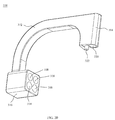
- the bone plate 200 may include a body 202 with a first end 204, a second end 206, and a transition point 208 positioned between the first end 204 and the second end 206.
- the body 202 may include a first portion 210, a second portion 220, and a connecting portion 240 attaching the first portion 210 to the second portion 220.
- the first portion 210 may extend from the first end 204 to the transition point 208.
- the second portion 220 may extend from the transition point 208 to the second end 206.
- the connecting portion 240 may be positioned between the first portion 210 and second portion 220 at the transition point 208.
- the first portion 210 may have at least one slot 212 near the first end 204 of the body 202, at least one first opening 214 positioned adjacent the at least one slot 212, and at least one channel 232 positioned between the at least one first opening 214 and the transition point 208.
- the at least one channel 232 may be positioned adjacent to the at least one slot 212.
- the slot 212, first opening 214, and channel 232 may be, for example, aligned along the center of the body 202.
- the slot 212 may be, for example, a compression screw hole for receiving a threaded fastener or screw (not shown).
- the opening 214 may be, for example, a screw hole for receiving a threaded fastener or screw (not shown).
- the channel 232 may be, for example, an opening for receiving an insertion tool.
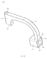
- the first portion 210 may also include an extension member or arm 216, as shown in FIGS. 9-11 and 13-16 .
- the extension member 216 may extend out from a side of the body 202 of the first portion 210 and may include at least one second opening 218.
- the extension member 216 may extend out from the body between the first end 204 and the transition point 208 and may be angled with respect to the longitudinal axis of the body 202. For example, the extension member 216 may extend out from the body near the first opening 214 and channel 232.
- the extension member 216 may be angled toward the second end 206 of the body 202.
- the extension member 216 may also be curved as it extends away from the body 202 as seen in FIG. 13 .
- the curvature of the extension member 216 may, for example, match the curvature of the bone engaging the first portion 210.
- the extension member 216 may be configured to reinforce the plantar aspect of the foot to reduce or restrict gapping after surgery by providing plantar support from a medial positioned plate 200.
- the extension member 216 may also be positioned in the direction that matches the normal transition of forces during the gait cycle to provide the greatest strength during peak loads.
- the extension member 216 may be shorter than the extension member 116.
- the extension member 216 may be positioned closer to the transition point 208 than the extension member 116 is positioned to the transition point 108.
- the first portion 210 of the plate 200 may include a dual curvature with, for example, a first curvature perpendicular to the long axis of the plate 200 and a second curvature along the long axis of the plate 200.
- the first curvature may have a radius of, for example, approximately 8 mm to 60 mm
- the second curvature may have a radius of, for example, approximately 50 mm to 300 mm.
- the first portion 210 near the first end 204 and including the slot 212 may be angled relative to the second curvature, as shown in FIGS. 11 and 12 .
- the second portion 220 may include a first lobe 222 and a second lobe 226 extending out from the body 202.
- the first lobe 222 may be offset from the second lobe 226 forming an angled surface at the second end 206 of the body 202 as seen in FIG. 15 .
- the first lobe 222 may include a third opening 224 and the second lobe 224 may include a fourth opening 228.
- Alternative numbers of lobes 222, 226 are also contemplated to provide for additional fastening locations for securing the plate 200 to the patient's bones.
- the openings 224, 228 may be, for example, screw holes for receiving threaded fasteners or screws (not shown).
- the second portion 220 may also include a ramped portion 230 positioned at the second end 206 along the angled surface.
- the ramped portion 230 is gradually angled from the bottom surface to the top surface of the body 202 and provides a surface that allows a tendon, for example, the anterior tibialis tendon, to glide over the plate 200.
- the ramped portion 230 has a more pronounced angle than the ramped portion 130. As discussed in greater detail above with respect to ramped portion 130, by allowing the tendon to glide over the plate soft-tissue irritation is eliminated.
- the ramped portion 230 may decrease the thickness of the plate at the second end 206, while still maintaining adequate thickness to prevent screw prominence.
- the connecting portion 240 is positioned relatively perpendicular to and couples the first portion 210 and the second portion 220.
- the connecting portion 240 provides a change in elevation or "step up" from the first portion 210 to the second portion 220.
- the connecting portion 240 may provide a step up of, for example, approximately 1 mm to 10 mm.
- the connecting portion 240 may include a sloped surface 242 on the top of the body 202.
- the connecting portion 240 may include a first transition portion 244 extending from the first portion 210 to the transition point 208 and a second transition portion 246 extending perpendicular to the first transition portion 244 from the transition point 208 to the second portion 220.
- the first transition portion 244 and second transition portion 246 may be relatively planar.
- the plate 200 may include multiple curved surfaces.
- the plate 200 may include dual curvatures with respect to the longitudinal axis of the plate 200, as shown in FIGS. 13-14 .
- the first portion 210 may have a first curvature in a medial-lateral direction with respect to the longitudinal axis of the plate 200.
- the first curvature may have a range of, for example, approximately 8 mm to 60 mm.
- the second portion 220 may have a second curvature in the medial-lateral direction along with respect to the longitudinal axis of the plate 200 along the bottom surface.
- the second curvature may have a range from, for example, approximately 10 mm to 60 mm.
- the first curvature and second curvature may be different in plate 200 to allow for the plate 200 to be used on the medial aspect of a patient's foot.
- the body 202 of the plate 200 may have a third curvature along a portion of the plate 200 in line with the longitudinal axis and the third curvature may have a range of, for example, approximately 50 mm to 300 mm.
- the first end 204 of the plate 200 may not be curved along the longitudinal axis of the plate.
- the plate curvatures may have radii that are positioned off axis to provide strength to the plates 100, 200 and to enable placement of the plates 100, 200 on the medial aspect of the patient's bone.
- the bone plate alignment guide apparatus 300 may include a body 310, a coupling member 330, and a guide pin tissue protector 340.
- the apparatus 300 may also include a guide wire or pin (not shown) and a fastener (not shown).
- the coupling member 330 may include a knob 332 and a shaft 334.
- the shaft portion 334 may include an engagement portion 336 for coupling to a bone plate, for example, bone plate 100 or 200, and a groove 338 which may assist with coupling the engagement portion 336 to a bone plate.
- the engagement portion 336 may be, for example, threaded to engage corresponding threads in an opening in a bone plate, deformable to be removeably press fit into the opening in the bone plate, or another similar configuration that achieves a coupling of the guide apparatus 300 to a bone plate, such as, bone plate 100, 200, or the like.
- the guide wire (not shown) may be, for example, a pin, k-wire, olive wire, or the like.
- the fastener (not shown) may be, for example, a compression screw, lag screw, headless screw, or a solid screw, for crossing a joint or fracture.
- the guide pin tissue protector 340 may include a handle portion 342 at a first end and a shaft portion 344 extending away from the handle portion 342 to a tip 348 at a second end.
- the shaft 344 may taper at the second end to form the tip 348.
- the guide pin tissue protector 340 may also include a through hole 346 extending from the first end to the second end to enable a guide wire (not shown) to pass through the tissue protector 340 and engage the patient's bone.
- the body 310 may include an arm 312 with an attachment portion 314 at a first end and an alignment portion 316 at a second end.
- the alignment portion 316 of the body 310 may be, for example, a variable hole alignment portion, and may include a plurality of holes 318.
- the plurality of holes 318 may be, for example four holes that are positioned in a square arrangement.
- the plurality of holes 318 may be straight or angled to a desired insertion position relative to the arm 312 of the body 310.
- the two left holes and two right holes may, for example, each be slightly angled toward the center of the alignment portion 316 such that each of the side holes converge toward each other.
- the top two holes and the bottom two holes may each be slightly angled toward the center of the alignment portion 316 such that each of the holes converge toward each other.
- Alternative angled arrangements for the holes 318 are also contemplated to enable a fastener to be inserted across two bones into a position that will not be in the path of the bone plate screws when they are inserted.
- the body 310 may also include a through hole 320 in the attachment portion 314 of the body 310, as seen in FIGS. 20-21 .
- the body 310 may include an alignment protrusion 322 extending away from the attachment portion 314, as shown in FIGS. 17-20 , for engaging an opening in a bone plate, such as bone plate 100, 200, or the like.
- the alignment protrusion 322 may be used to position the bone plate alignment guide apparatus 300 with respect to a bone plate.
- the alignment guide 300 may be used with plates 100 and 200.
- the alignment guide 300 and plate 100 or 200 form a bone plate insertion system that allows for the insertion of a crossing fastener and the bone plate screws without either contacting the other.
- the bone plate insertion systems provide a surgeon the ability to precisely place the crossing fastener and bone plate screws without the need for additional imaging or trial and error, thereby improving the surgical procedure.
- the method may include preparing the patient's bones 400 and aligning the patient's bones 410.
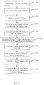
- the method may include selecting a bone plate 420 and attaching an insertion guide to the bone plate 430. Once the bone plate is coupled to the insertion guide, the bone plate may be aligned on the patient's bones 440. Then, the bone plate may be secured to the patient's bones with temporary fixation members 450. After the bone plate is secured to the bones, a guide wire may be inserted across the patient's joint 460 and the insertion guide may then be removed from the bone plate 470. Next, the guide wire may be used to insert a screw across the joint 380. Finally, the screws may be inserted to secure the plate to the bones and the temporary fixation members removed 490.
- the method as shown in FIG. 22 may be described in greater detail with reference to FIGS. 1-21 .
- the surgeon will prepare the patient's bones by selecting the cartilage removal technique, for example, curettage or sagittal saw blade. If the surgeon selects to use a curettage, then the correction method will be translation of the bone, for example, the metatarsal. However, if the surgeon selects to use a sagittal saw blade, then the correction method will be angular correction of the joint, for example, the tarso-metatarsal joint.
- the bones Once the bones are prepared, they will be aligned for fixation and a guide wire may be inserted to temporarily stabilize the joint.
- a bone plate alignment guide apparatus 300 may be secured to the selected bone plate 100, 200.
- the apparatus 300 may be secured by aligning the alignment protrusion 322 of the guide 300 with an opening (not shown) in the plate 100, 200 and inserting coupling member 330 through the opening 320 in the body 310 and securing the engagement portion 336 to another opening in the plate 100, 200.
- the plate 100, 200 may be aligned onto the patient's bones.
- the plate 100, 200 is aligned with the long axis of the plate 100, 200 being parallel to the long axis of the bone, for example, metatarsal bone, to ensure proper orientation of the guide 300.
- the plate 100, 200 is secured to the bones using at least two temporary fixation members, for example, olive wires.
- the first temporary fixation member may be inserted into the proximal screw hole in the plate 100, 200 and the second into a second opening in the plate 100, 200.
- the first temporary fixation member may be inserted into openings 124, 128 or 224, 228 and the second temporary fixation member may be inserted into the slot 112, 212.
- the guide pin tissue protector 340 may be inserted into one of the through holes 318 in the body 310. Then, a guide wire may be inserted through the hole 346 and across the joint. Once the guide wire is determined to be in the correct position, the protector 340 may be removed from the body 310 and the coupling member 330 may be disengaged from the bone plate 100, 200 and the coupling member 330 and body 310 removed from the bone plate 100,200.
- a screw insertion technique for inserting a crossing fastener for example, a compression lag screw, may be employed to insert the crossing fastener through the joint.
- the crossing fastener is preferably inserted over the guide wire to obtain proper positioning to avoid contact with the bone plate screws when they are later inserted.
- the guide wire may be removed.
- screws (not shown) may be inserted into the patient's bones through the bone plate 100, 200. The screws may be inserted by, for example, using a threaded drill guide to drill the openings for the screws, then the openings are measured, and finally the screws are inserted into the openings.
- the screws may be, for example, locking screws, non-locking screws, or a combination thereof.
- any olive wires, k-wires, or guide wires that have not yet been removed from the patient's bones may be removed. Finally, the patient's surgical opening may be closed.
- a method or device that "comprises,” “has,” “includes,” or “contains” one or more steps or elements possesses those one or more steps or elements, but is not limited to possessing only those one or more steps or elements.
- a step of a method or an element of a device that "comprises,” “has,” “includes,” or “contains” one or more features possesses those one or more features, but is not limited to possessing only those one or more features.
- a device or structure that is configured in a certain way is configured in at least that way, but may also be configured in ways that are not listed.
Landscapes
- Health & Medical Sciences (AREA)
- Orthopedic Medicine & Surgery (AREA)
- Surgery (AREA)
- Life Sciences & Earth Sciences (AREA)
- Heart & Thoracic Surgery (AREA)
- Veterinary Medicine (AREA)
- Engineering & Computer Science (AREA)
- Biomedical Technology (AREA)
- Nuclear Medicine, Radiotherapy & Molecular Imaging (AREA)
- Medical Informatics (AREA)
- Molecular Biology (AREA)
- Animal Behavior & Ethology (AREA)
- General Health & Medical Sciences (AREA)
- Public Health (AREA)
- Neurology (AREA)
- Dentistry (AREA)
- Oral & Maxillofacial Surgery (AREA)
- Surgical Instruments (AREA)
Abstract
Description
- The present invention relates generally to the field of orthopedics related to orthopedic bone plates, specifically, step off bone plates, bone plate insertion systems, and methods for using the bone plates.
- Currently, the lapidus procedure is performed at the base of the first metatarsal and involves the cuneiform. Typically, surgeons perform sagittal saw cuts to provide the proper realignment of the joint. The cutting of the joint shortens the first metatarsal and could off load the sesamoids which may alter normal pressures on the foot. In order to correct for this shortening, surgeons will not only correct the position in the transverse plane (hallux valgus), but will also plantar translate or angulate the metatarsal to reload the sesamoids. In order to achieve this, surgeons may utilize an off-set style plate that is positioned dorsal medial on the joint thus translating the cut bone down and over. However, a dorsal medial positioned plate is not ideal due to the forces imparted on the plate post-operatively.
- Accordingly, the present invention contemplates a newly configured and improved bone plate and methods which overcome the above-referenced problems and others.
- The present invention is directed toward step off bone plates, bone plate insertion systems, and methods of using the devices.
- In one aspect, provided herein is a step off bone plate. The step off bone plate may include, for example, a body with a first end and a second end. The body may include a first portion with a first curvature, a second portion with a second curvature, and a connecting portion coupled to the first portion at a first end and coupled to the second portion at a second end.
- In another aspect, provided herein is a bone plate insertion system. The bone plate insertion system may include, for example, a bone plate with a first and second end and an alignment guide apparatus. The bone plate may include, for example, a first portion with a first curvature, a second portion with a second curvature, and a connecting portion. The connecting portion connects the first portion to the second portion.
- In yet another aspect, provided herein is a method for using the step off bone plate. The method includes, for example, preparing and aligning a patient's bones. The method may also include selecting a step off bone plate and attaching an insertion guide to the step off bone plate. The method may further include aligning the step off bone plate over the bones and securing the bone plate to the bones with temporary fixation members. In addition, the method may include inserting a guide wire through the insertion guide and across the bones and removing the insertion guide from the step off bone plate. The method may further include inserting a screw over the guide wire and across the bones. The method may also include inserting bone screws to secure the plate to the patient's bones. Further, the method may include closing the patient.
- These, and other objects, features and advantages of this invention will become apparent from the following detailed description of the various aspects of the invention taken in conjunction with the accompanying drawings.
- The accompanying drawings, which are incorporated in and constitute a part of the specification, illustrate embodiments of the invention and together with the detailed description herein, serve to explain the principles of the invention. It is emphasized that, in accordance with the standard practice in the industry, various features are not drawn to scale. In fact, the dimensions of the various features may be arbitrarily increased or reduced for clarity of discussion. The drawings are only for purposes of illustrating preferred embodiments and are not to be construed as limiting the invention.
-
FIG. 1 is a top perspective view of a step off bone plate, in accordance with an aspect of the present invention; -
FIG. 2 is a bottom perspective view of the step off bone plate ofFIG. 1 , in accordance with an aspect of the present invention; -
FIG. 3 a first side view of the step off bone plate ofFIG. 1 , in accordance with an aspect of the present invention; -
FIG. 4 is a second side view of the step off bone plate ofFIG. 1 , in accordance with an aspect of the present invention; -
FIG. 5 is a front view of the step off bone plate ofFIG. 1 , in accordance with an aspect of the present invention; -
FIG. 6 is a back view of the step off bone plate ofFIG. 1 , in accordance with an aspect of the present invention; -
FIG. 7 is a top view of the step off bone plate ofFIG. 1 , in accordance with an aspect of the present invention; -
FIG. 8 is a bottom view of the step off bone plate ofFIG. 1 , in accordance with an aspect of the present invention; -
FIG. 9 is a top perspective view of another step off bone plate, in accordance with an aspect of the present invention; -
FIG. 10 is a bottom perspective view of the step off bone plate ofFIG. 9 , in accordance with an aspect of the present invention; -
FIG. 11 a first side view of the step off bone plate ofFIG. 9 , in accordance with an aspect of the present invention; -
FIG. 12 is a second side view of the step off bone plate ofFIG. 9 , in accordance with an aspect of the present invention; -
FIG. 13 is a front view of the step off bone plate ofFIG. 9 , in accordance with an aspect of the present invention; -
FIG. 14 is a back view of the step off bone plate ofFIG. 9 , in accordance with an aspect of the present invention; -
FIG. 15 is a top view of the step off bone plate ofFIG. 9 , in accordance with an aspect of the present invention; -
FIG. 16 is a bottom view of the step off bone plate ofFIG. 9 , in accordance with an aspect of the present invention; and -
FIG. 17 is a perspective view of a bone plate alignment guide apparatus, in accordance with an aspect of the present invention; -
FIG. 18 is a side view of the bone plate alignment guide apparatus ofFIG. 17 , in accordance with an aspect of the present invention; -
FIG. 19 is an exploded side view of the bone plate alignment guide apparatus ofFIG. 17 , in accordance with an aspect of the present invention; -
FIG. 20 is a bottom perspective view of the body of the bone plate alignment guide apparatus ofFIG. 17 , in accordance with an aspect of the present invention; -
FIG. 21 is an end perspective view of the body of the bone plate alignment guide apparatus ofFIG. 17 , in accordance with an aspect of the present invention; and -
FIG. 22 depicts one embodiment of a method for using the step off bone plate, in accordance with an aspect of the present invention. - Generally stated, disclosed herein is an embodiment of a step off bone plate. The terms "step off bone plate," "bone plate," and "plate" may be used interchangeably herein as they essentially refer to the same device. Further, a method for using the step off bone plate is discussed.
- In this detailed description and the following claims, the words proximal, distal, anterior, posterior, medial, lateral, superior, inferior, dorsal and plantar are defined by their standard usage for indicating a particular part of a bone or implant according to the relative disposition of the natural bone or directional terms of reference. For example, "proximal" means the portion of an implant nearest the torso, while "distal" indicates the portion of the implant farthest from the torso. As for directional terms, "anterior" is a direction towards the front side of the body, "posterior" means a direction towards the back side of the body, "medial" means towards the midline of the body, "lateral" is a direction towards the sides or away from the midline of the body, "superior" means a direction above and "inferior" means a direction below another object or structure. Further, specifically in regards to the foot, the term "dorsal" refers to the top of the foot and the term "plantar" refers the bottom of the foot.
- Referring to the drawings, wherein like reference numerals are used to indicate like or analogous components throughout the several views, and with particular reference to
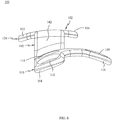
FIGS. 1-8 , abone plate 100, for example, a step off bone plate, is shown. Thebone plate 100 is designed for medial wall positioning to provide abone plate 100 with a dual curvature along the long axis of theplate 100 to match the correction of a more dorsally located plate. The dual curvatures of theplate 100 allow for theplate 100 to be positioned medially thereby providing a more stable construct and a plate that resists bending. - The step off
bone plate 100, as shown inFIGS. 1-8 , includes abody 102 with afirst end 104, asecond end 106, and atransition point 108 positioned between thefirst end 104 and thesecond end 106. Thebody 102 may include afirst portion 110, asecond portion 120, and a connectingportion 140 coupling thefirst portion 110 to thesecond portion 120. Thefirst portion 110 may extend from thefirst end 104 to thetransition point 108. Thesecond portion 120 may extend from thetransition point 108 to thesecond end 106. The connectingportion 140 may be positioned between thefirst portion 110 andsecond portion 120 at thetransition point 108. - As shown in
FIGS. 1-8 , thefirst portion 110 may have at least oneslot 112 near thefirst end 104 of thebody 102 and at least onefirst opening 114 positioned between the at least oneslot 112 and thetransition point 108. As depicted, the at least onefirst opening 114 may be positioned adjacent to the at least oneslot 112. Theslot 112 andfirst opening 114 may be, for example, aligned along the center of thebody 102. Theopening 114 may be, for example, a screw hole for receiving a threaded fastener or screw (not shown). Thefirst portion 110 may also include an extension member orarm 116, as shown inFIGS. 1-3 and 5-8 . Theextension member 116 may extend out from a side of thebody 102 of thefirst portion 110 and may include at least onesecond opening 118. Theextension member 116 may extend out from the body between thefirst end 104 and thetransition point 108 and may be angled with respect to the longitudinal axis of thebody 102. For example, theextension member 116 may extend out from the body near thefirst opening 114. Theextension member 116 may be angled toward thesecond end 106 of thebody 102. Theextension member 116 may also be curved as it extends away from thebody 102 as seen inFIG. 5 . The curvature of theextension member 116 may, for example, match the curvature of the bone engaging thefirst portion 110. Theextension member 116 may be configured to reinforce the plantar aspect of the foot to reduce or restrict gapping after surgery by providing plantar support from a medial positionedplate 100. Theextension member 116 may also be positioned in the direction that matches the normal transition of stress during the gait cycle to provide the greatest strength during peak loads. Thefirst portion 110 of theplate 100 may include a dual curvature with, for example, a first curvature perpendicular to the long axis of theplate 100 and a second curvature along the long axis of theplate 100. The first curvature may have a radius of, for example, approximately 8 mm to 60 mm, and the second curvature may have a radius of, for example, approximately 50 mm to 300 mm. - The
second portion 120, as shown inFIGS. 1-2 and 7-8 , may include afirst lobe 122 and asecond lobe 126 extending out from thebody 102. Thefirst lobe 122 may be offset from thesecond lobe 126 forming an angled surface at thesecond end 106 of thebody 102 as seen inFIG. 5 . Thefirst lobe 122 may include athird opening 124 and thesecond lobe 124 may include afourth opening 128. Alternative numbers oflobes plate 100 to the patient's bones. Theopenings second portion 120 may also include a rampedportion 130 positioned at thesecond end 106 along the angled surface. The rampedportion 130 is gradually angled from the bottom surface to the top surface of thebody 102 and provides a surface that allows a tendon, for example, the anterior tibialis tendon, to glide over theplate 100. By allowing the tendon to glide over the plate soft-tissue irritation is eliminated. Existing plate designs cause the tendon to pop or jump over the plate resulting in patient discomfort. The rampedportion 130 may decrease the thickness of the plate at thesecond end 106, while still maintaining adequate thickness to prevent screw prominence. - Referring now to
FIGS. 1-4 , the connectingportion 140 is positioned relatively perpendicular to and couples thefirst portion 110 and thesecond portion 120. The connectingportion 140 provides a change in elevation or "step up" from thefirst portion 110 to thesecond portion 120. The connectingportion 140 may provide a step up of, for example, approximately 1 mm to 10 mm. The connectingportion 140 may include asloped surface 142 on the top of thebody 102. In addition, the connectingportion 140 may include afirst transition portion 144 extending from thefirst portion 110 to thetransition point 108 and asecond transition portion 146 extending perpendicular to thefirst transition portion 144 from thetransition point 108 to thesecond portion 120. Thefirst transition portion 144 andsecond transition portion 146 may be relatively planar. - As shown in
FIGS. 3-6 , theplate 100 may include multiple curved surfaces. Theplate 100 may include dual curvatures with respect to the longitudinal axis of theplate 100, as shown inFIGS. 5-6 . Thefirst portion 110 may have a first curvature in a medial-lateral direction with respect to the longitudinal axis of theplate 100. The first curvature may have a range of, for example, approximately 8 mm to 60 mm. Thesecond portion 120 may have a second curvature in the medial-lateral direction along with respect to the longitudinal axis of theplate 100 along the bottom surface. The second curvature may have a range from, for example, approximately 10 mm to 60 mm. The first curvature and second curvature may be different inplate 100 to allow for theplate 100 to be used on the medial aspect of a patient's foot. As shown inFIGS. 3-4 , thebody 102 of theplate 100 may have a third curvature in line with the longitudinal axis and the third curvature may have a range of, for example, approximately 50 mm to 300 mm. - Referring now to
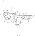
FIGS. 9-16 , another step offbone plate 200 is shown. Thebone plate 200 may include abody 202 with afirst end 204, asecond end 206, and atransition point 208 positioned between thefirst end 204 and thesecond end 206. Thebody 202 may include afirst portion 210, asecond portion 220, and a connectingportion 240 attaching thefirst portion 210 to thesecond portion 220. Thefirst portion 210 may extend from thefirst end 204 to thetransition point 208. Thesecond portion 220 may extend from thetransition point 208 to thesecond end 206. The connectingportion 240 may be positioned between thefirst portion 210 andsecond portion 220 at thetransition point 208. - As shown in
FIGS. 9-16 , thefirst portion 210 may have at least oneslot 212 near thefirst end 204 of thebody 202, at least onefirst opening 214 positioned adjacent the at least oneslot 212, and at least onechannel 232 positioned between the at least onefirst opening 214 and thetransition point 208. As depicted, the at least onechannel 232 may be positioned adjacent to the at least oneslot 212. Theslot 212,first opening 214, andchannel 232 may be, for example, aligned along the center of thebody 202. Theslot 212 may be, for example, a compression screw hole for receiving a threaded fastener or screw (not shown). Theopening 214 may be, for example, a screw hole for receiving a threaded fastener or screw (not shown). Thechannel 232 may be, for example, an opening for receiving an insertion tool. Thefirst portion 210 may also include an extension member orarm 216, as shown inFIGS. 9-11 and 13-16 . Theextension member 216 may extend out from a side of thebody 202 of thefirst portion 210 and may include at least onesecond opening 218. Theextension member 216 may extend out from the body between thefirst end 204 and thetransition point 208 and may be angled with respect to the longitudinal axis of thebody 202. For example, theextension member 216 may extend out from the body near thefirst opening 214 andchannel 232. Theextension member 216 may be angled toward thesecond end 206 of thebody 202. Theextension member 216 may also be curved as it extends away from thebody 202 as seen inFIG. 13 . The curvature of theextension member 216 may, for example, match the curvature of the bone engaging thefirst portion 210. Theextension member 216 may be configured to reinforce the plantar aspect of the foot to reduce or restrict gapping after surgery by providing plantar support from a medial positionedplate 200. Theextension member 216 may also be positioned in the direction that matches the normal transition of forces during the gait cycle to provide the greatest strength during peak loads. Theextension member 216 may be shorter than theextension member 116. In addition, theextension member 216 may be positioned closer to thetransition point 208 than theextension member 116 is positioned to thetransition point 108. - The
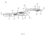
first portion 210 of theplate 200 may include a dual curvature with, for example, a first curvature perpendicular to the long axis of theplate 200 and a second curvature along the long axis of theplate 200. The first curvature may have a radius of, for example, approximately 8 mm to 60 mm, and the second curvature may have a radius of, for example, approximately 50 mm to 300 mm. Thefirst portion 210 near thefirst end 204 and including theslot 212 may be angled relative to the second curvature, as shown inFIGS. 11 and12 . - The
second portion 220, as shown inFIGS. 9-10 and 15-16 , may include afirst lobe 222 and asecond lobe 226 extending out from thebody 202. Thefirst lobe 222 may be offset from thesecond lobe 226 forming an angled surface at thesecond end 206 of thebody 202 as seen inFIG. 15 . Thefirst lobe 222 may include athird opening 224 and thesecond lobe 224 may include afourth opening 228. Alternative numbers oflobes plate 200 to the patient's bones. Theopenings second portion 220 may also include a rampedportion 230 positioned at thesecond end 206 along the angled surface. The rampedportion 230 is gradually angled from the bottom surface to the top surface of thebody 202 and provides a surface that allows a tendon, for example, the anterior tibialis tendon, to glide over theplate 200. The rampedportion 230 has a more pronounced angle than the rampedportion 130. As discussed in greater detail above with respect to rampedportion 130, by allowing the tendon to glide over the plate soft-tissue irritation is eliminated. The rampedportion 230 may decrease the thickness of the plate at thesecond end 206, while still maintaining adequate thickness to prevent screw prominence. - Referring now to
FIGS. 9-12 , the connectingportion 240 is positioned relatively perpendicular to and couples thefirst portion 210 and thesecond portion 220. The connectingportion 240 provides a change in elevation or "step up" from thefirst portion 210 to thesecond portion 220. The connectingportion 240 may provide a step up of, for example, approximately 1 mm to 10 mm. The connectingportion 240 may include asloped surface 242 on the top of thebody 202. In addition, the connectingportion 240 may include afirst transition portion 244 extending from thefirst portion 210 to thetransition point 208 and asecond transition portion 246 extending perpendicular to thefirst transition portion 244 from thetransition point 208 to thesecond portion 220. Thefirst transition portion 244 andsecond transition portion 246 may be relatively planar. - As shown in
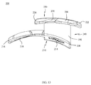
FIGS. 11-16 , theplate 200 may include multiple curved surfaces. Theplate 200 may include dual curvatures with respect to the longitudinal axis of theplate 200, as shown inFIGS. 13-14 . Thefirst portion 210 may have a first curvature in a medial-lateral direction with respect to the longitudinal axis of theplate 200. The first curvature may have a range of, for example, approximately 8 mm to 60 mm. Thesecond portion 220 may have a second curvature in the medial-lateral direction along with respect to the longitudinal axis of theplate 200 along the bottom surface. The second curvature may have a range from, for example, approximately 10 mm to 60 mm. The first curvature and second curvature may be different inplate 200 to allow for theplate 200 to be used on the medial aspect of a patient's foot. As shown inFIGS. 11-12 , thebody 202 of theplate 200 may have a third curvature along a portion of theplate 200 in line with the longitudinal axis and the third curvature may have a range of, for example, approximately 50 mm to 300 mm. Thefirst end 204 of theplate 200 may not be curved along the longitudinal axis of the plate. The plate curvatures may have radii that are positioned off axis to provide strength to theplates plates - Referring now to
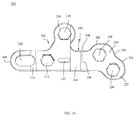
FIGS. 17-21 , a bone platealignment guide apparatus 300 is shown. The bone platealignment guide apparatus 300 may include abody 310, acoupling member 330, and a guidepin tissue protector 340. Theapparatus 300 may also include a guide wire or pin (not shown) and a fastener (not shown). Thecoupling member 330 may include aknob 332 and ashaft 334. Theshaft portion 334 may include anengagement portion 336 for coupling to a bone plate, for example,bone plate groove 338 which may assist with coupling theengagement portion 336 to a bone plate. Theengagement portion 336 may be, for example, threaded to engage corresponding threads in an opening in a bone plate, deformable to be removeably press fit into the opening in the bone plate, or another similar configuration that achieves a coupling of theguide apparatus 300 to a bone plate, such as,bone plate - The guide
pin tissue protector 340, as shown inFIGS. 17-19 , may include ahandle portion 342 at a first end and ashaft portion 344 extending away from thehandle portion 342 to atip 348 at a second end. Theshaft 344 may taper at the second end to form thetip 348. The guidepin tissue protector 340 may also include a throughhole 346 extending from the first end to the second end to enable a guide wire (not shown) to pass through thetissue protector 340 and engage the patient's bone. - As shown in
FIGS. 17-21 , thebody 310 may include anarm 312 with anattachment portion 314 at a first end and analignment portion 316 at a second end. Thealignment portion 316 of thebody 310 may be, for example, a variable hole alignment portion, and may include a plurality ofholes 318. The plurality ofholes 318 may be, for example four holes that are positioned in a square arrangement. The plurality ofholes 318 may be straight or angled to a desired insertion position relative to thearm 312 of thebody 310. By way of specific example, the two left holes and two right holes may, for example, each be slightly angled toward the center of thealignment portion 316 such that each of the side holes converge toward each other. In addition, the top two holes and the bottom two holes may each be slightly angled toward the center of thealignment portion 316 such that each of the holes converge toward each other. Alternative angled arrangements for theholes 318 are also contemplated to enable a fastener to be inserted across two bones into a position that will not be in the path of the bone plate screws when they are inserted. Thebody 310 may also include a throughhole 320 in theattachment portion 314 of thebody 310, as seen inFIGS. 20-21 . Further, thebody 310 may include analignment protrusion 322 extending away from theattachment portion 314, as shown inFIGS. 17-20 , for engaging an opening in a bone plate, such asbone plate alignment protrusion 322 may be used to position the bone platealignment guide apparatus 300 with respect to a bone plate. - The
alignment guide 300 may be used withplates alignment guide 300 andplate - Referring now to
FIG. 22 , a method of using the step offbone plate systems FIG. 22 , the method may include preparing the patient'sbones 400 and aligning the patient'sbones 410. Next, the method may include selecting abone plate 420 and attaching an insertion guide to thebone plate 430. Once the bone plate is coupled to the insertion guide, the bone plate may be aligned on the patient'sbones 440. Then, the bone plate may be secured to the patient's bones withtemporary fixation members 450. After the bone plate is secured to the bones, a guide wire may be inserted across the patient's joint 460 and the insertion guide may then be removed from thebone plate 470. Next, the guide wire may be used to insert a screw across the joint 380. Finally, the screws may be inserted to secure the plate to the bones and the temporary fixation members removed 490. - The method as shown in
FIG. 22 may be described in greater detail with reference toFIGS. 1-21 . First, the surgeon will prepare the patient's bones by selecting the cartilage removal technique, for example, curettage or sagittal saw blade. If the surgeon selects to use a curettage, then the correction method will be translation of the bone, for example, the metatarsal. However, if the surgeon selects to use a sagittal saw blade, then the correction method will be angular correction of the joint, for example, the tarso-metatarsal joint. Once the bones are prepared, they will be aligned for fixation and a guide wire may be inserted to temporarily stabilize the joint. The surgeon will then select a bone plate, for example,bone plate bone plates alignment guide apparatus 300 may be secured to the selectedbone plate apparatus 300 may be secured by aligning thealignment protrusion 322 of theguide 300 with an opening (not shown) in theplate coupling member 330 through theopening 320 in thebody 310 and securing theengagement portion 336 to another opening in theplate - Once the
guide 300 is coupled to theplate plate plate plate guide 300. Next, theplate plate plate openings slot plate pin tissue protector 340 may be inserted into one of the throughholes 318 in thebody 310. Then, a guide wire may be inserted through thehole 346 and across the joint. Once the guide wire is determined to be in the correct position, theprotector 340 may be removed from thebody 310 and thecoupling member 330 may be disengaged from thebone plate coupling member 330 andbody 310 removed from the bone plate 100,200. - After the
guide 300 is removed, a screw insertion technique for inserting a crossing fastener, for example, a compression lag screw, may be employed to insert the crossing fastener through the joint. The crossing fastener is preferably inserted over the guide wire to obtain proper positioning to avoid contact with the bone plate screws when they are later inserted. Once the fastener is inserted, the guide wire may be removed. Next, screws (not shown) may be inserted into the patient's bones through thebone plate guide 300 correctly positions the crossing fastener such that it is not in the path of any of the bone plate screw openings. Once theplate - The terminology used herein is for the purpose of describing particular embodiments only and is not intended to be limiting of the invention. As used herein, the singular forms "a", "an" and "the" are intended to include the plural forms as well, unless the context clearly indicates otherwise. It will be further understood that the terms "comprise" (and any form of comprise, such as "comprises" and "comprising"), "have" (and any form of have, such as "has", and "having"), "include" (and any form of include, such as "includes" and "including"), and "contain" (and any form of contain, such as "contains" and "containing") are open-ended linking verbs. As a result, a method or device that "comprises," "has," "includes," or "contains" one or more steps or elements possesses those one or more steps or elements, but is not limited to possessing only those one or more steps or elements. Likewise, a step of a method or an element of a device that "comprises," "has," "includes," or "contains" one or more features possesses those one or more features, but is not limited to possessing only those one or more features. Furthermore, a device or structure that is configured in a certain way is configured in at least that way, but may also be configured in ways that are not listed.
- The invention has been described with reference to the preferred embodiments. It will be understood that the architectural and operational embodiments described herein are exemplary of a plurality of possible arrangements to provide the same general features, characteristics, and general system operation. Modifications and alterations will occur to others upon a reading and understanding of the preceding detailed description. It is intended that the invention be construed as including all such modifications and alterations.
Claims (15)
- A bone plate, comprising:a body with a first end and a second end, the body further comprising;a first portion with a first curvature;a second portion with a second curvature; anda connecting portion, wherein the connecting portion connects the first portion to the second portion.
- The bone plate of claim 1, wherein the first curvature is larger than the second curvature and the body is curved along a longitudinal axis.
- The bone plate of claim 2, wherein the first curvature ranges from 8 mm to 60 mm and the curvature along the longitudinal axis ranges from 50 mm to 300 mm.
- The bone plate of claim 1, wherein the first portion comprises:an extension arm extending away from a side of the body; anda slot extending through the first portion of the body near the first end.
- The bone plate of claim 4, wherein the first portion further comprises:a first opening extending through the body adjacent to the slot; anda second opening extending through the extension arm.
- The bone plate of claim 5, wherein the second portion comprises:a first lobe; anda second lobe offset from the first lobe.
- The bone plate of claim 6, wherein the second portion further comprises:a ramped surface on the second end of the body.
- The bone plate of claim 7, wherein the ramped surface is angled from a bottom surface of the body to a top surface of the body.
- The bone plate of claim 8, wherein the first lobe and the second lobe each include an opening extending from a top surface of the second portion through a bottom surface of the second portion.
- The bone plate of claim 9, wherein the connecting portion comprises a perpendicular distance between the first portion and the second portion.
- The bone plate of claim 10, wherein the first portion is fixed to a bottom of the connecting portion, the second portion is fixed to a top of the connecting portion, and the first portion is offset in a vertical direction from the second portion.
- The bone plate of claim 4, wherein the extension arm is curved along the first curvature of the first portion and angled toward the second portion.
- A bone plate insertion system, comprising:a bone plate with a first end and a second end, the bone plate further comprising;a first portion with a first curvature;a second portion with a second curvature; anda connecting portion, wherein the connecting portion connects the first portion to the second portion; andan alignment guide apparatus.
- The bone plate insertion system of claim 13, wherein the alignment guide apparatus, comprises:a body, comprising:an arm with a first end and a second end;an attachment portion at the first end; andan alignment portion at the second end with at least one opening;a coupling member with a knob and a shaft, wherein the shaft passes through the attachment portion;a protector member with a handle portion and a shaft portion, wherein the shaft portion passes through the alignment portion;wherein the coupling member attaches the alignment guide apparatus to the bone plate.
- The bone plate insertion system of claim 14, wherein the alignment portion is square.
Applications Claiming Priority (1)
| Application Number | Priority Date | Filing Date | Title |
|---|---|---|---|
| US14/547,616 US9980760B2 (en) | 2014-11-19 | 2014-11-19 | Step off bone plates, systems, and methods of use |
Publications (3)
| Publication Number | Publication Date |
|---|---|
| EP3023068A2 true EP3023068A2 (en) | 2016-05-25 |
| EP3023068A3 EP3023068A3 (en) | 2016-08-31 |
| EP3023068B1 EP3023068B1 (en) | 2021-02-17 |
Family
ID=54548109
Family Applications (1)
| Application Number | Title | Priority Date | Filing Date |
|---|---|---|---|
| EP15195121.7A Active EP3023068B1 (en) | 2014-11-19 | 2015-11-18 | Bone plates, plate alignment systems, and methods of use |
Country Status (3)
| Country | Link |
|---|---|
| US (1) | US9980760B2 (en) |
| EP (1) | EP3023068B1 (en) |
| ES (1) | ES2869344T3 (en) |
Cited By (30)
| Publication number | Priority date | Publication date | Assignee | Title |
|---|---|---|---|---|
| CN105943149A (en) * | 2016-06-02 | 2016-09-21 | 北京德益达美医疗科技有限公司 | Fixing method for treating distal tibiofibular separation |
| WO2019014356A1 (en) | 2017-07-11 | 2019-01-17 | Paragon 28, Inc. | Bone fixation system, assembly, implants, devices, insertion guides, and methods of use |
| WO2021055932A1 (en) | 2019-09-20 | 2021-03-25 | New Generation Devices, Inc. | Tibial plateau leveling osteotomy plate with offset |
| US11123120B2 (en) | 2018-07-11 | 2021-09-21 | Paragon 28, Inc. | Implants, alignment guides, systems and methods of use |
| US11395691B2 (en) | 2012-12-28 | 2022-07-26 | Paragon 28, Inc. | Alignment guide apparatus, methods and systems |
| US11497528B2 (en) | 2014-07-15 | 2022-11-15 | Treace Medical Concepts, Inc. | Bone positioning and cutting system and method |
| US11583323B2 (en) | 2018-07-12 | 2023-02-21 | Treace Medical Concepts, Inc. | Multi-diameter bone pin for installing and aligning bone fixation plate while minimizing bone damage |
| US11596443B2 (en) | 2018-07-11 | 2023-03-07 | Treace Medical Concepts, Inc. | Compressor-distractor for angularly realigning bone portions |
| US11602387B2 (en) | 2015-08-14 | 2023-03-14 | Treace Medical Concepts, Inc. | Bone positioning and preparing guide systems and methods |
| US11602386B2 (en) | 2015-07-14 | 2023-03-14 | Treace Medical Concepts, Inc. | Bone positioning guide |
| US11607250B2 (en) | 2019-02-13 | 2023-03-21 | Treace Medical Concepts, Inc. | Tarsal-metatarsal joint procedure utilizing compressor-distractor and instrument providing sliding surface |
| US11622797B2 (en) | 2020-01-31 | 2023-04-11 | Treace Medical Concepts, Inc. | Metatarsophalangeal joint preparation and metatarsal realignment for fusion |
| US11627954B2 (en) | 2019-08-07 | 2023-04-18 | Treace Medical Concepts, Inc. | Bi-planar instrument for bone cutting and joint realignment procedure |
| US11642142B2 (en) | 2016-10-24 | 2023-05-09 | Paragon 28, Inc. | Osteotomy systems, devices and methods |
| US11648019B2 (en) | 2015-09-18 | 2023-05-16 | Treace Medical Concepts, Inc. | Joint spacer systems and methods |
| US11666345B2 (en) | 2017-02-27 | 2023-06-06 | Paragon 28, Inc. | Intramedullary nail alignment guides, fixation guides, devices, systems, and methods of use |
| US11690659B2 (en) | 2015-08-14 | 2023-07-04 | Treace Medical Concepts, Inc. | Tarsal-metatarsal joint procedure utilizing fulcrum |
| US11779381B2 (en) | 2017-03-30 | 2023-10-10 | Paragon 28, Inc. | Bone fixation system, assembly, implants, devices, alignment guides, and methods of use |
| US11786257B2 (en) | 2015-01-07 | 2023-10-17 | Treace Medical Concepts, Inc. | Bone cutting guide systems and methods |
| US11844533B2 (en) | 2015-02-18 | 2023-12-19 | Treace Medical Concepts, Inc. | Pivotable bone cutting guide useful for bone realignment and compression techniques |
| USD1011524S1 (en) | 2022-02-23 | 2024-01-16 | Treace Medical Concepts, Inc. | Compressor-distractor for the foot |
| US11889998B1 (en) | 2019-09-12 | 2024-02-06 | Treace Medical Concepts, Inc. | Surgical pin positioning lock |
| US11890039B1 (en) | 2019-09-13 | 2024-02-06 | Treace Medical Concepts, Inc. | Multi-diameter K-wire for orthopedic applications |
| USD1018854S1 (en) | 2020-09-21 | 2024-03-19 | Movora, Llc | Tibial plate |
| US11931047B2 (en) | 2016-08-26 | 2024-03-19 | Treace Medical Concepts, Inc. | Osteotomy procedure for correcting bone misalignment |
| US11963703B2 (en) | 2015-07-14 | 2024-04-23 | Treace Medical Concepts, Inc. | Bone cutting guide systems and methods |
| US11969193B2 (en) | 2015-05-06 | 2024-04-30 | Treace Medical Concepts, Inc. | Intra-osseous plate system and method |
| US11986251B2 (en) | 2019-09-13 | 2024-05-21 | Treace Medical Concepts, Inc. | Patient-specific osteotomy instrumentation |
| US12004789B2 (en) | 2020-05-19 | 2024-06-11 | Treace Medical Concepts, Inc. | Devices and techniques for treating metatarsus adductus |
| US12102368B2 (en) | 2024-04-05 | 2024-10-01 | Treace Medical Concepts, Inc. | Bone positioning guide |
Families Citing this family (11)
| Publication number | Priority date | Publication date | Assignee | Title |
|---|---|---|---|---|
| US20150335365A1 (en) * | 2014-05-24 | 2015-11-26 | Neutin Orthopedics, LLC | Fixation device for a mau-type osteotomy procedure |
| US10420596B2 (en) * | 2016-08-17 | 2019-09-24 | Globus Medical, Inc. | Volar distal radius stabilization system |
| WO2018157170A1 (en) | 2017-02-27 | 2018-08-30 | Paragon 28, Inc. | Targeting instruments, systems and methods of use |
| US11185356B2 (en) | 2017-12-08 | 2021-11-30 | Paragon 28, Inc. | Bone fixation assembly, implants and methods of use |
| WO2020168058A1 (en) | 2019-02-13 | 2020-08-20 | Paragon 28, Inc. | Implant, alignment guides, system and methods of use |
| AU2020221356A1 (en) | 2019-02-14 | 2021-10-07 | Paragon 28, Inc. | Threaded targeting instruments, systems and methods of use |
| WO2021051098A1 (en) | 2019-09-13 | 2021-03-18 | Inmotus Medical Llc | Patient-specific surgical methods and instrumentation |
| USD945623S1 (en) * | 2019-09-20 | 2022-03-08 | New Generation Devices, Inc. | Tibial plate |
| USD931461S1 (en) * | 2020-03-11 | 2021-09-21 | DePuy Synthes Products, Inc. | Bone plate |
| USD931462S1 (en) * | 2020-03-11 | 2021-09-21 | DePuy Synthes Products, Inc. | Bone plate |
| CN114176750A (en) * | 2021-12-08 | 2022-03-15 | 重庆熙科医疗科技有限公司 | Dorsal correction plate for first metatarsal distal Scarf osteotomy |
Family Cites Families (40)
| Publication number | Priority date | Publication date | Assignee | Title |
|---|---|---|---|---|
| CH681199A5 (en) | 1990-07-23 | 1993-02-15 | Synthes Ag | |
| US5350380A (en) | 1993-01-15 | 1994-09-27 | Depuy Inc. | Method for securing a ligament replacement in a bone |
| IL105183A (en) | 1993-03-28 | 1996-07-23 | Yehiel Gotfried | Surgical device for connection of fractured bones |
| FR2706763A1 (en) | 1993-06-25 | 1994-12-30 | Implants Ind Sa | Osteosynthesis plate |
| GB9823974D0 (en) | 1998-11-02 | 1998-12-30 | Grampian Healthcare National H | Fracture treatment |
| US6342057B1 (en) | 2000-04-28 | 2002-01-29 | Synthes (Usa) | Remotely aligned surgical drill guide |
| US8475504B2 (en) | 2007-07-19 | 2013-07-02 | Acumed Llc | Method of bone fixation with slender spanning members disposed outside bone |
| ATE489904T1 (en) | 2001-06-27 | 2010-12-15 | Depuy Products Inc | MINIMAL INVASIVE ORTHOPEDIC DEVICE |
| DE20110948U1 (en) | 2001-07-02 | 2001-09-06 | Aesculap AG & Co. KG, 78532 Tuttlingen | Surgical instrument |
| US7270666B2 (en) | 2002-05-15 | 2007-09-18 | Linvatec Corporation | Cross-pin graft fixation, instruments, and methods |
| US7011665B2 (en) | 2002-07-22 | 2006-03-14 | Sdgi Holdings, Inc. | Guide assembly for engaging a bone plate to a bony segment |
| DE10348932B4 (en) | 2003-10-18 | 2006-01-19 | Intercus Gmbh | System for the minimally invasive treatment of a proximal humeral or femoral fracture |
| EP1718222B1 (en) | 2004-02-20 | 2009-11-18 | Synthes GmbH | Aiming device for inserting stable-angle, long screws in the articular region of a bone |
| WO2006091827A2 (en) * | 2005-02-25 | 2006-08-31 | Regents Of The University Of California | Device and template for canine humeral slide osteotomy |
| US8118846B2 (en) | 2005-01-28 | 2012-02-21 | Orthohelix Surgical Designs, Inc. | Orthopedic plates for use in clavicle repair and methods for their use |
| US7896886B2 (en) | 2005-01-28 | 2011-03-01 | Depuy Products, Inc. | Nail plate and implantation jig therefor |
| US8100952B2 (en) * | 2005-12-22 | 2012-01-24 | Anthem Orthopaedics Llc | Drug delivering bone plate and method and targeting device for use therewith |
| US8057520B2 (en) | 2006-07-18 | 2011-11-15 | Orthohelix Surgical Designs, Inc. | Calcaneal plate |
| FR2905590B1 (en) | 2006-09-11 | 2008-12-05 | Surge Foot | ARTHRODESIS PLATE OF A METATARSO-PHALANGEAL ARTICULATION. |
| DE102007036943B4 (en) | 2007-08-04 | 2014-12-31 | Zimmer Gmbh | Foot surgery bone plate |
| DE102007047576B4 (en) | 2007-10-04 | 2015-01-08 | Zimmer Gmbh | Foot bone plate as well as system |
| WO2009105201A1 (en) | 2008-02-19 | 2009-08-27 | Orthohelix Surgical Designs, Inc. | Orthopedic plates for use in the midfoot |
| CN201223440Y (en) | 2008-07-17 | 2009-04-22 | 傅宏 | Three-dimensional dissection type anterior steel plate for acetabulum |
| US8192441B2 (en) | 2008-10-03 | 2012-06-05 | Howmedica Osteonics Corp. | High tibial osteotomy instrumentation |
| US8828063B2 (en) | 2008-11-19 | 2014-09-09 | Amei Technologies, Inc. | Fixation plate for use in the Lapidus approach |
| CN201365972Y (en) | 2009-03-12 | 2009-12-23 | 占开喜 | Tibial plateau back-side dissection bone fracture plate |
| US8529608B2 (en) | 2009-04-28 | 2013-09-10 | Osteomed Llc | Bone plate with a transfixation screw hole |
| WO2011066280A1 (en) | 2009-11-27 | 2011-06-03 | Synthes Usa, Llc | Plating concept for distal radial fractures |
| JP5808393B2 (en) | 2010-04-27 | 2015-11-10 | ジンテス ゲゼルシャフト ミット ベシュレンクテル ハフツング | Bone fixation system for pressing K-wire |
| US8764807B2 (en) | 2010-06-10 | 2014-07-01 | Arthrex, Inc. | Calcaneus step plate |
| GB2487331B (en) | 2010-09-27 | 2012-10-24 | Acumed Llc | Instruments having a radiopaque region to facilitate positioning a bone plate on bone |
| CN103561666B (en) | 2011-05-25 | 2016-08-17 | 新特斯有限责任公司 | There is the sighting device of radiopaque label |
| CN202218914U (en) | 2011-08-28 | 2012-05-16 | 泰州市中兴医械科技有限公司 | Minimally-invasive compression bone plate for femoral neck and intertrochanteric comminuted fracture rear side |
| US20140148859A1 (en) | 2012-11-27 | 2014-05-29 | Solana Surgical, Llc | Orthopedic fusion plate and compression screw |
| US9283008B2 (en) * | 2012-12-17 | 2016-03-15 | Toby Orthopaedics, Inc. | Bone plate for plate osteosynthesis and method for use thereof |
| US20140180348A1 (en) | 2012-12-21 | 2014-06-26 | Wright Medical Technology, Inc. | Trajectory guide |
| WO2015094409A1 (en) | 2013-12-20 | 2015-06-25 | Paragon 28, Inc. | Alignment guide apparatus, methods and systems |
| EP2938279B1 (en) | 2012-12-28 | 2018-11-14 | Paragon 28, Inc. | Alignment guide system |
| US9545276B2 (en) | 2013-03-15 | 2017-01-17 | Aristotech Industries Gmbh | Fixation device and method of use for a lapidus-type plantar hallux valgus procedure |
| CN203417254U (en) | 2013-07-16 | 2014-02-05 | 江苏双羊医疗器械有限公司 | Anatomical type locking calcaneus bone fracture plate |
-
2014
- 2014-11-19 US US14/547,616 patent/US9980760B2/en active Active
-
2015
- 2015-11-18 EP EP15195121.7A patent/EP3023068B1/en active Active
- 2015-11-18 ES ES15195121T patent/ES2869344T3/en active Active
Non-Patent Citations (1)
| Title |
|---|
| None |
Cited By (41)
| Publication number | Priority date | Publication date | Assignee | Title |
|---|---|---|---|---|
| US11395691B2 (en) | 2012-12-28 | 2022-07-26 | Paragon 28, Inc. | Alignment guide apparatus, methods and systems |
| US11779382B2 (en) | 2012-12-28 | 2023-10-10 | Paragon 28, Inc. | Alignment guide apparatus, methods and systems |
| US11771467B2 (en) | 2014-07-15 | 2023-10-03 | Treace Medical Concepts, Inc. | Bone positioning and cutting system and method |
| US11937849B2 (en) | 2014-07-15 | 2024-03-26 | Treace Medical Concepts, Inc. | Bone positioning and cutting system and method |
| US11497528B2 (en) | 2014-07-15 | 2022-11-15 | Treace Medical Concepts, Inc. | Bone positioning and cutting system and method |
| US11523845B2 (en) | 2014-07-15 | 2022-12-13 | Treace Medical Concepts, Inc. | Bone positioning and cutting system and method |
| US11786257B2 (en) | 2015-01-07 | 2023-10-17 | Treace Medical Concepts, Inc. | Bone cutting guide systems and methods |
| US11844533B2 (en) | 2015-02-18 | 2023-12-19 | Treace Medical Concepts, Inc. | Pivotable bone cutting guide useful for bone realignment and compression techniques |
| US11969193B2 (en) | 2015-05-06 | 2024-04-30 | Treace Medical Concepts, Inc. | Intra-osseous plate system and method |
| US11602386B2 (en) | 2015-07-14 | 2023-03-14 | Treace Medical Concepts, Inc. | Bone positioning guide |
| US11963703B2 (en) | 2015-07-14 | 2024-04-23 | Treace Medical Concepts, Inc. | Bone cutting guide systems and methods |
| US11950819B2 (en) | 2015-07-14 | 2024-04-09 | Treace Medical Concepts, Inc. | Bone positioning guide |
| US11911085B2 (en) | 2015-08-14 | 2024-02-27 | Treace Medical Concepts, Inc. | Bone positioning and preparing guide systems and methods |
| US11602387B2 (en) | 2015-08-14 | 2023-03-14 | Treace Medical Concepts, Inc. | Bone positioning and preparing guide systems and methods |
| US11690659B2 (en) | 2015-08-14 | 2023-07-04 | Treace Medical Concepts, Inc. | Tarsal-metatarsal joint procedure utilizing fulcrum |
| US11771443B2 (en) | 2015-09-18 | 2023-10-03 | Treace Medical Concepts, Inc. | Joint spacer systems and methods |
| US11648019B2 (en) | 2015-09-18 | 2023-05-16 | Treace Medical Concepts, Inc. | Joint spacer systems and methods |
| CN105943149B (en) * | 2016-06-02 | 2019-04-02 | 北京德益达美医疗科技有限公司 | A kind of fixed system of Distal tibiofibular diastasis |
| CN105943149A (en) * | 2016-06-02 | 2016-09-21 | 北京德益达美医疗科技有限公司 | Fixing method for treating distal tibiofibular separation |
| US11931047B2 (en) | 2016-08-26 | 2024-03-19 | Treace Medical Concepts, Inc. | Osteotomy procedure for correcting bone misalignment |
| US11642142B2 (en) | 2016-10-24 | 2023-05-09 | Paragon 28, Inc. | Osteotomy systems, devices and methods |
| US11666345B2 (en) | 2017-02-27 | 2023-06-06 | Paragon 28, Inc. | Intramedullary nail alignment guides, fixation guides, devices, systems, and methods of use |
| US11779381B2 (en) | 2017-03-30 | 2023-10-10 | Paragon 28, Inc. | Bone fixation system, assembly, implants, devices, alignment guides, and methods of use |
| US11559316B2 (en) | 2017-07-11 | 2023-01-24 | Paragon 28, Inc. | Bone fixation system, assembly, implants, devices, insertion guides, and methods of use |
| WO2019014356A1 (en) | 2017-07-11 | 2019-01-17 | Paragon 28, Inc. | Bone fixation system, assembly, implants, devices, insertion guides, and methods of use |
| EP3651699A4 (en) * | 2017-07-11 | 2021-05-19 | Paragon 28, Inc. | Bone fixation system, assembly, implants, devices, insertion guides, and methods of use |
| US11123120B2 (en) | 2018-07-11 | 2021-09-21 | Paragon 28, Inc. | Implants, alignment guides, systems and methods of use |
| US11596443B2 (en) | 2018-07-11 | 2023-03-07 | Treace Medical Concepts, Inc. | Compressor-distractor for angularly realigning bone portions |
| US11583323B2 (en) | 2018-07-12 | 2023-02-21 | Treace Medical Concepts, Inc. | Multi-diameter bone pin for installing and aligning bone fixation plate while minimizing bone damage |
| US11607250B2 (en) | 2019-02-13 | 2023-03-21 | Treace Medical Concepts, Inc. | Tarsal-metatarsal joint procedure utilizing compressor-distractor and instrument providing sliding surface |
| US11627954B2 (en) | 2019-08-07 | 2023-04-18 | Treace Medical Concepts, Inc. | Bi-planar instrument for bone cutting and joint realignment procedure |
| US11889998B1 (en) | 2019-09-12 | 2024-02-06 | Treace Medical Concepts, Inc. | Surgical pin positioning lock |
| US11890039B1 (en) | 2019-09-13 | 2024-02-06 | Treace Medical Concepts, Inc. | Multi-diameter K-wire for orthopedic applications |
| US11986251B2 (en) | 2019-09-13 | 2024-05-21 | Treace Medical Concepts, Inc. | Patient-specific osteotomy instrumentation |
| EP4031039A4 (en) * | 2019-09-20 | 2023-10-25 | New Generation Devices, Inc. | Tibial plateau leveling osteotomy plate with offset |
| WO2021055932A1 (en) | 2019-09-20 | 2021-03-25 | New Generation Devices, Inc. | Tibial plateau leveling osteotomy plate with offset |
| US11622797B2 (en) | 2020-01-31 | 2023-04-11 | Treace Medical Concepts, Inc. | Metatarsophalangeal joint preparation and metatarsal realignment for fusion |
| US12004789B2 (en) | 2020-05-19 | 2024-06-11 | Treace Medical Concepts, Inc. | Devices and techniques for treating metatarsus adductus |
| USD1018854S1 (en) | 2020-09-21 | 2024-03-19 | Movora, Llc | Tibial plate |
| USD1011524S1 (en) | 2022-02-23 | 2024-01-16 | Treace Medical Concepts, Inc. | Compressor-distractor for the foot |
| US12102368B2 (en) | 2024-04-05 | 2024-10-01 | Treace Medical Concepts, Inc. | Bone positioning guide |
Also Published As
| Publication number | Publication date |
|---|---|
| ES2869344T3 (en) | 2021-10-25 |
| US9980760B2 (en) | 2018-05-29 |
| EP3023068A3 (en) | 2016-08-31 |
| US20160135858A1 (en) | 2016-05-19 |
| EP3023068B1 (en) | 2021-02-17 |
Similar Documents
| Publication | Publication Date | Title |
|---|---|---|
| EP3023068B1 (en) | Bone plates, plate alignment systems, and methods of use | |
| US11395691B2 (en) | Alignment guide apparatus, methods and systems | |
| US11344347B2 (en) | Bone plating kit for foot and ankle applications | |
| US10918431B2 (en) | Bone fixation system, assembly, implants, devices, alignment guides, and methods of use | |
| EP3091911B1 (en) | Resection guides | |
| US9949773B2 (en) | Orthopedic bone plate and locking tab apparatus and method of use | |
| US11185356B2 (en) | Bone fixation assembly, implants and methods of use | |
| WO2015094409A1 (en) | Alignment guide apparatus, methods and systems | |
| US20240215994A1 (en) | Implant, alignment guides, system and methods of use | |
| US20220000525A1 (en) | Implants, alignment guides, systems and methods of use | |
| EP2938300B1 (en) | Orthopedic bone plate and locking tab apparatus |
Legal Events
| Date | Code | Title | Description |
|---|---|---|---|
| AK | Designated contracting states |
Kind code of ref document: A2 Designated state(s): AL AT BE BG CH CY CZ DE DK EE ES FI FR GB GR HR HU IE IS IT LI LT LU LV MC MK MT NL NO PL PT RO RS SE SI SK SM TR |
|
| AX | Request for extension of the european patent |
Extension state: BA ME |
|
| PUAI | Public reference made under article 153(3) epc to a published international application that has entered the european phase |
Free format text: ORIGINAL CODE: 0009012 |
|
| PUAL | Search report despatched |
Free format text: ORIGINAL CODE: 0009013 |
|
| AK | Designated contracting states |
Kind code of ref document: A3 Designated state(s): AL AT BE BG CH CY CZ DE DK EE ES FI FR GB GR HR HU IE IS IT LI LT LU LV MC MK MT NL NO PL PT RO RS SE SI SK SM TR |
|
| AX | Request for extension of the european patent |
Extension state: BA ME |
|
| RIC1 | Information provided on ipc code assigned before grant |
Ipc: A61B 17/80 20060101AFI20160722BHEP |
|
| STAA | Information on the status of an ep patent application or granted ep patent |
Free format text: STATUS: THE APPLICATION HAS BEEN PUBLISHED |
|
| STAA | Information on the status of an ep patent application or granted ep patent |
Free format text: STATUS: REQUEST FOR EXAMINATION WAS MADE |
|
| 17P | Request for examination filed |
Effective date: 20170607 |
|
| RBV | Designated contracting states (corrected) |
Designated state(s): AL AT BE BG CH CY CZ DE DK EE ES FI FR GB GR HR HU IE IS IT LI LT LU LV MC MK MT NL NO PL PT RO RS SE SI SK SM TR |
|
| STAA | Information on the status of an ep patent application or granted ep patent |
Free format text: STATUS: EXAMINATION IS IN PROGRESS |
|
| 17Q | First examination report despatched |
Effective date: 20180925 |
|
| GRAP | Despatch of communication of intention to grant a patent |
Free format text: ORIGINAL CODE: EPIDOSNIGR1 |
|
| STAA | Information on the status of an ep patent application or granted ep patent |
Free format text: STATUS: GRANT OF PATENT IS INTENDED |
|
| INTG | Intention to grant announced |
Effective date: 20200828 |
|
| GRAS | Grant fee paid |
Free format text: ORIGINAL CODE: EPIDOSNIGR3 |
|
| GRAA | (expected) grant |
Free format text: ORIGINAL CODE: 0009210 |
|
| STAA | Information on the status of an ep patent application or granted ep patent |
Free format text: STATUS: THE PATENT HAS BEEN GRANTED |
|
| AK | Designated contracting states |
Kind code of ref document: B1 Designated state(s): AL AT BE BG CH CY CZ DE DK EE ES FI FR GB GR HR HU IE IS IT LI LT LU LV MC MK MT NL NO PL PT RO RS SE SI SK SM TR |
|
| REG | Reference to a national code |
Ref country code: GB Ref legal event code: FG4D |
|
| REG | Reference to a national code |
Ref country code: CH Ref legal event code: EP |
|
| REG | Reference to a national code |
Ref country code: DE Ref legal event code: R096 Ref document number: 602015065521 Country of ref document: DE |
|
| REG | Reference to a national code |
Ref country code: AT Ref legal event code: REF Ref document number: 1360436 Country of ref document: AT Kind code of ref document: T Effective date: 20210315 |
|
| REG | Reference to a national code |
Ref country code: IE Ref legal event code: FG4D |
|
| REG | Reference to a national code |
Ref country code: NL Ref legal event code: FP |
|
| REG | Reference to a national code |
Ref country code: LT Ref legal event code: MG9D |
|
| PG25 | Lapsed in a contracting state [announced via postgrant information from national office to epo] |
Ref country code: LT Free format text: LAPSE BECAUSE OF FAILURE TO SUBMIT A TRANSLATION OF THE DESCRIPTION OR TO PAY THE FEE WITHIN THE PRESCRIBED TIME-LIMIT Effective date: 20210217 Ref country code: PT Free format text: LAPSE BECAUSE OF FAILURE TO SUBMIT A TRANSLATION OF THE DESCRIPTION OR TO PAY THE FEE WITHIN THE PRESCRIBED TIME-LIMIT Effective date: 20210617 Ref country code: GR Free format text: LAPSE BECAUSE OF FAILURE TO SUBMIT A TRANSLATION OF THE DESCRIPTION OR TO PAY THE FEE WITHIN THE PRESCRIBED TIME-LIMIT Effective date: 20210518 Ref country code: FI Free format text: LAPSE BECAUSE OF FAILURE TO SUBMIT A TRANSLATION OF THE DESCRIPTION OR TO PAY THE FEE WITHIN THE PRESCRIBED TIME-LIMIT Effective date: 20210217 Ref country code: HR Free format text: LAPSE BECAUSE OF FAILURE TO SUBMIT A TRANSLATION OF THE DESCRIPTION OR TO PAY THE FEE WITHIN THE PRESCRIBED TIME-LIMIT Effective date: 20210217 Ref country code: BG Free format text: LAPSE BECAUSE OF FAILURE TO SUBMIT A TRANSLATION OF THE DESCRIPTION OR TO PAY THE FEE WITHIN THE PRESCRIBED TIME-LIMIT Effective date: 20210517 Ref country code: NO Free format text: LAPSE BECAUSE OF FAILURE TO SUBMIT A TRANSLATION OF THE DESCRIPTION OR TO PAY THE FEE WITHIN THE PRESCRIBED TIME-LIMIT Effective date: 20210517 |
|
| REG | Reference to a national code |
Ref country code: AT Ref legal event code: MK05 Ref document number: 1360436 Country of ref document: AT Kind code of ref document: T Effective date: 20210217 |
|
| PG25 | Lapsed in a contracting state [announced via postgrant information from national office to epo] |
Ref country code: SE Free format text: LAPSE BECAUSE OF FAILURE TO SUBMIT A TRANSLATION OF THE DESCRIPTION OR TO PAY THE FEE WITHIN THE PRESCRIBED TIME-LIMIT Effective date: 20210217 Ref country code: RS Free format text: LAPSE BECAUSE OF FAILURE TO SUBMIT A TRANSLATION OF THE DESCRIPTION OR TO PAY THE FEE WITHIN THE PRESCRIBED TIME-LIMIT Effective date: 20210217 Ref country code: PL Free format text: LAPSE BECAUSE OF FAILURE TO SUBMIT A TRANSLATION OF THE DESCRIPTION OR TO PAY THE FEE WITHIN THE PRESCRIBED TIME-LIMIT Effective date: 20210217 Ref country code: LV Free format text: LAPSE BECAUSE OF FAILURE TO SUBMIT A TRANSLATION OF THE DESCRIPTION OR TO PAY THE FEE WITHIN THE PRESCRIBED TIME-LIMIT Effective date: 20210217 |
|
| PG25 | Lapsed in a contracting state [announced via postgrant information from national office to epo] |
Ref country code: IS Free format text: LAPSE BECAUSE OF FAILURE TO SUBMIT A TRANSLATION OF THE DESCRIPTION OR TO PAY THE FEE WITHIN THE PRESCRIBED TIME-LIMIT Effective date: 20210617 |
|
| REG | Reference to a national code |
Ref country code: ES Ref legal event code: FG2A Ref document number: 2869344 Country of ref document: ES Kind code of ref document: T3 Effective date: 20211025 |
|
| PG25 | Lapsed in a contracting state [announced via postgrant information from national office to epo] |
Ref country code: EE Free format text: LAPSE BECAUSE OF FAILURE TO SUBMIT A TRANSLATION OF THE DESCRIPTION OR TO PAY THE FEE WITHIN THE PRESCRIBED TIME-LIMIT Effective date: 20210217 Ref country code: CZ Free format text: LAPSE BECAUSE OF FAILURE TO SUBMIT A TRANSLATION OF THE DESCRIPTION OR TO PAY THE FEE WITHIN THE PRESCRIBED TIME-LIMIT Effective date: 20210217 Ref country code: SM Free format text: LAPSE BECAUSE OF FAILURE TO SUBMIT A TRANSLATION OF THE DESCRIPTION OR TO PAY THE FEE WITHIN THE PRESCRIBED TIME-LIMIT Effective date: 20210217 Ref country code: AT Free format text: LAPSE BECAUSE OF FAILURE TO SUBMIT A TRANSLATION OF THE DESCRIPTION OR TO PAY THE FEE WITHIN THE PRESCRIBED TIME-LIMIT Effective date: 20210217 |
|
| REG | Reference to a national code |
Ref country code: DE Ref legal event code: R097 Ref document number: 602015065521 Country of ref document: DE |
|
| PG25 | Lapsed in a contracting state [announced via postgrant information from national office to epo] |
Ref country code: DK Free format text: LAPSE BECAUSE OF FAILURE TO SUBMIT A TRANSLATION OF THE DESCRIPTION OR TO PAY THE FEE WITHIN THE PRESCRIBED TIME-LIMIT Effective date: 20210217 Ref country code: SK Free format text: LAPSE BECAUSE OF FAILURE TO SUBMIT A TRANSLATION OF THE DESCRIPTION OR TO PAY THE FEE WITHIN THE PRESCRIBED TIME-LIMIT Effective date: 20210217 Ref country code: RO Free format text: LAPSE BECAUSE OF FAILURE TO SUBMIT A TRANSLATION OF THE DESCRIPTION OR TO PAY THE FEE WITHIN THE PRESCRIBED TIME-LIMIT Effective date: 20210217 |
|
| PLBE | No opposition filed within time limit |
Free format text: ORIGINAL CODE: 0009261 |
|
| STAA | Information on the status of an ep patent application or granted ep patent |
Free format text: STATUS: NO OPPOSITION FILED WITHIN TIME LIMIT |
|
| 26N | No opposition filed |
Effective date: 20211118 |
|
| PG25 | Lapsed in a contracting state [announced via postgrant information from national office to epo] |
Ref country code: AL Free format text: LAPSE BECAUSE OF FAILURE TO SUBMIT A TRANSLATION OF THE DESCRIPTION OR TO PAY THE FEE WITHIN THE PRESCRIBED TIME-LIMIT Effective date: 20210217 |
|
| PG25 | Lapsed in a contracting state [announced via postgrant information from national office to epo] |
Ref country code: SI Free format text: LAPSE BECAUSE OF FAILURE TO SUBMIT A TRANSLATION OF THE DESCRIPTION OR TO PAY THE FEE WITHIN THE PRESCRIBED TIME-LIMIT Effective date: 20210217 |
|
| PG25 | Lapsed in a contracting state [announced via postgrant information from national office to epo] |
Ref country code: IT Free format text: LAPSE BECAUSE OF FAILURE TO SUBMIT A TRANSLATION OF THE DESCRIPTION OR TO PAY THE FEE WITHIN THE PRESCRIBED TIME-LIMIT Effective date: 20210217 |
|
| PG25 | Lapsed in a contracting state [announced via postgrant information from national office to epo] |
Ref country code: IS Free format text: LAPSE BECAUSE OF FAILURE TO SUBMIT A TRANSLATION OF THE DESCRIPTION OR TO PAY THE FEE WITHIN THE PRESCRIBED TIME-LIMIT Effective date: 20210617 |
|
| PG25 | Lapsed in a contracting state [announced via postgrant information from national office to epo] |
Ref country code: MC Free format text: LAPSE BECAUSE OF FAILURE TO SUBMIT A TRANSLATION OF THE DESCRIPTION OR TO PAY THE FEE WITHIN THE PRESCRIBED TIME-LIMIT Effective date: 20210217 |
|
| REG | Reference to a national code |
Ref country code: CH Ref legal event code: PL |
|
| PG25 | Lapsed in a contracting state [announced via postgrant information from national office to epo] |
Ref country code: LU Free format text: LAPSE BECAUSE OF NON-PAYMENT OF DUE FEES Effective date: 20211118 Ref country code: BE Free format text: LAPSE BECAUSE OF NON-PAYMENT OF DUE FEES Effective date: 20211130 |
|
| REG | Reference to a national code |
Ref country code: BE Ref legal event code: MM Effective date: 20211130 |
|
| PG25 | Lapsed in a contracting state [announced via postgrant information from national office to epo] |
Ref country code: IE Free format text: LAPSE BECAUSE OF NON-PAYMENT OF DUE FEES Effective date: 20211118 |
|
| PG25 | Lapsed in a contracting state [announced via postgrant information from national office to epo] |
Ref country code: HU Free format text: LAPSE BECAUSE OF FAILURE TO SUBMIT A TRANSLATION OF THE DESCRIPTION OR TO PAY THE FEE WITHIN THE PRESCRIBED TIME-LIMIT; INVALID AB INITIO Effective date: 20151118 |
|
| PG25 | Lapsed in a contracting state [announced via postgrant information from national office to epo] |
Ref country code: CY Free format text: LAPSE BECAUSE OF FAILURE TO SUBMIT A TRANSLATION OF THE DESCRIPTION OR TO PAY THE FEE WITHIN THE PRESCRIBED TIME-LIMIT Effective date: 20210217 |
|
| PG25 | Lapsed in a contracting state [announced via postgrant information from national office to epo] |
Ref country code: LI Free format text: LAPSE BECAUSE OF NON-PAYMENT OF DUE FEES Effective date: 20220630 Ref country code: CH Free format text: LAPSE BECAUSE OF NON-PAYMENT OF DUE FEES Effective date: 20220630 |
|
| PGFP | Annual fee paid to national office [announced via postgrant information from national office to epo] |
Ref country code: NL Payment date: 20231020 Year of fee payment: 9 |
|
| PGFP | Annual fee paid to national office [announced via postgrant information from national office to epo] |
Ref country code: GB Payment date: 20231019 Year of fee payment: 9 |
|
| PGFP | Annual fee paid to national office [announced via postgrant information from national office to epo] |
Ref country code: ES Payment date: 20231201 Year of fee payment: 9 |
|
| PGFP | Annual fee paid to national office [announced via postgrant information from national office to epo] |
Ref country code: FR Payment date: 20231019 Year of fee payment: 9 Ref country code: DE Payment date: 20231019 Year of fee payment: 9 |
|
| PG25 | Lapsed in a contracting state [announced via postgrant information from national office to epo] |
Ref country code: MK Free format text: LAPSE BECAUSE OF FAILURE TO SUBMIT A TRANSLATION OF THE DESCRIPTION OR TO PAY THE FEE WITHIN THE PRESCRIBED TIME-LIMIT Effective date: 20210217 |