EP3023066A1 - Pedicle screw system and spinal column-stabilizing system - Google Patents
Pedicle screw system and spinal column-stabilizing system Download PDFInfo
- Publication number
- EP3023066A1 EP3023066A1 EP15195766.9A EP15195766A EP3023066A1 EP 3023066 A1 EP3023066 A1 EP 3023066A1 EP 15195766 A EP15195766 A EP 15195766A EP 3023066 A1 EP3023066 A1 EP 3023066A1
- Authority
- EP
- European Patent Office
- Prior art keywords
- coupling
- pedicle screw
- bone
- screw
- alignment
- Prior art date
- Legal status (The legal status is an assumption and is not a legal conclusion. Google has not performed a legal analysis and makes no representation as to the accuracy of the status listed.)
- Granted
Links
- 230000008878 coupling Effects 0.000 claims abstract description 201
- 238000010168 coupling process Methods 0.000 claims abstract description 201
- 238000005859 coupling reaction Methods 0.000 claims abstract description 201
- 210000000988 bone and bone Anatomy 0.000 claims abstract description 126
- 230000006641 stabilisation Effects 0.000 claims abstract description 19
- 238000011105 stabilization Methods 0.000 claims abstract description 19
- 238000004873 anchoring Methods 0.000 description 10
- 241000309551 Arthraxon hispidus Species 0.000 description 4
- 238000010276 construction Methods 0.000 description 2
- 230000002349 favourable effect Effects 0.000 description 2
- 238000003780 insertion Methods 0.000 description 2
- 230000037431 insertion Effects 0.000 description 2
- 241000722921 Tulipa gesneriana Species 0.000 description 1
- 238000000149 argon plasma sintering Methods 0.000 description 1
- 230000005540 biological transmission Effects 0.000 description 1
- 230000015572 biosynthetic process Effects 0.000 description 1
- 230000000903 blocking effect Effects 0.000 description 1
- 238000005520 cutting process Methods 0.000 description 1
- 238000005553 drilling Methods 0.000 description 1
- 238000003384 imaging method Methods 0.000 description 1
- 238000002513 implantation Methods 0.000 description 1
- 238000004519 manufacturing process Methods 0.000 description 1
- 238000000034 method Methods 0.000 description 1
- 238000003801 milling Methods 0.000 description 1
- 238000005457 optimization Methods 0.000 description 1
- 238000010079 rubber tapping Methods 0.000 description 1
- 238000007493 shaping process Methods 0.000 description 1
Images


Classifications
-
- A—HUMAN NECESSITIES
- A61—MEDICAL OR VETERINARY SCIENCE; HYGIENE
- A61B—DIAGNOSIS; SURGERY; IDENTIFICATION
- A61B17/00—Surgical instruments, devices or methods, e.g. tourniquets
- A61B17/56—Surgical instruments or methods for treatment of bones or joints; Devices specially adapted therefor
- A61B17/58—Surgical instruments or methods for treatment of bones or joints; Devices specially adapted therefor for osteosynthesis, e.g. bone plates, screws, setting implements or the like
- A61B17/68—Internal fixation devices, including fasteners and spinal fixators, even if a part thereof projects from the skin
- A61B17/70—Spinal positioners or stabilisers ; Bone stabilisers comprising fluid filler in an implant
- A61B17/7001—Screws or hooks combined with longitudinal elements which do not contact vertebrae
- A61B17/7035—Screws or hooks, wherein a rod-clamping part and a bone-anchoring part can pivot relative to each other
- A61B17/7037—Screws or hooks, wherein a rod-clamping part and a bone-anchoring part can pivot relative to each other wherein pivoting is blocked when the rod is clamped
-
- A—HUMAN NECESSITIES
- A61—MEDICAL OR VETERINARY SCIENCE; HYGIENE
- A61B—DIAGNOSIS; SURGERY; IDENTIFICATION
- A61B17/00—Surgical instruments, devices or methods, e.g. tourniquets
- A61B17/56—Surgical instruments or methods for treatment of bones or joints; Devices specially adapted therefor
- A61B17/58—Surgical instruments or methods for treatment of bones or joints; Devices specially adapted therefor for osteosynthesis, e.g. bone plates, screws, setting implements or the like
- A61B17/68—Internal fixation devices, including fasteners and spinal fixators, even if a part thereof projects from the skin
- A61B17/70—Spinal positioners or stabilisers ; Bone stabilisers comprising fluid filler in an implant
- A61B17/7001—Screws or hooks combined with longitudinal elements which do not contact vertebrae
- A61B17/7032—Screws or hooks with U-shaped head or back through which longitudinal rods pass
-
- A—HUMAN NECESSITIES
- A61—MEDICAL OR VETERINARY SCIENCE; HYGIENE
- A61B—DIAGNOSIS; SURGERY; IDENTIFICATION
- A61B17/00—Surgical instruments, devices or methods, e.g. tourniquets
- A61B17/56—Surgical instruments or methods for treatment of bones or joints; Devices specially adapted therefor
- A61B17/58—Surgical instruments or methods for treatment of bones or joints; Devices specially adapted therefor for osteosynthesis, e.g. bone plates, screws, setting implements or the like
- A61B17/68—Internal fixation devices, including fasteners and spinal fixators, even if a part thereof projects from the skin
- A61B17/70—Spinal positioners or stabilisers ; Bone stabilisers comprising fluid filler in an implant
- A61B17/7001—Screws or hooks combined with longitudinal elements which do not contact vertebrae
- A61B17/7035—Screws or hooks, wherein a rod-clamping part and a bone-anchoring part can pivot relative to each other
- A61B17/704—Screws or hooks, wherein a rod-clamping part and a bone-anchoring part can pivot relative to each other the longitudinal element passing through a ball-joint in the screw head
-
- A—HUMAN NECESSITIES
- A61—MEDICAL OR VETERINARY SCIENCE; HYGIENE
- A61B—DIAGNOSIS; SURGERY; IDENTIFICATION
- A61B17/00—Surgical instruments, devices or methods, e.g. tourniquets
- A61B17/56—Surgical instruments or methods for treatment of bones or joints; Devices specially adapted therefor
- A61B17/58—Surgical instruments or methods for treatment of bones or joints; Devices specially adapted therefor for osteosynthesis, e.g. bone plates, screws, setting implements or the like
- A61B17/68—Internal fixation devices, including fasteners and spinal fixators, even if a part thereof projects from the skin
- A61B17/70—Spinal positioners or stabilisers ; Bone stabilisers comprising fluid filler in an implant
- A61B17/7001—Screws or hooks combined with longitudinal elements which do not contact vertebrae
- A61B17/7044—Screws or hooks combined with longitudinal elements which do not contact vertebrae also having plates, staples or washers bearing on the vertebrae
-
- A—HUMAN NECESSITIES
- A61—MEDICAL OR VETERINARY SCIENCE; HYGIENE
- A61B—DIAGNOSIS; SURGERY; IDENTIFICATION
- A61B17/00—Surgical instruments, devices or methods, e.g. tourniquets
- A61B17/56—Surgical instruments or methods for treatment of bones or joints; Devices specially adapted therefor
- A61B17/58—Surgical instruments or methods for treatment of bones or joints; Devices specially adapted therefor for osteosynthesis, e.g. bone plates, screws, setting implements or the like
- A61B17/68—Internal fixation devices, including fasteners and spinal fixators, even if a part thereof projects from the skin
- A61B17/70—Spinal positioners or stabilisers ; Bone stabilisers comprising fluid filler in an implant
- A61B17/7074—Tools specially adapted for spinal fixation operations other than for bone removal or filler handling
- A61B17/7076—Tools specially adapted for spinal fixation operations other than for bone removal or filler handling for driving, positioning or assembling spinal clamps or bone anchors specially adapted for spinal fixation
- A61B17/7077—Tools specially adapted for spinal fixation operations other than for bone removal or filler handling for driving, positioning or assembling spinal clamps or bone anchors specially adapted for spinal fixation for moving bone anchors attached to vertebrae, thereby displacing the vertebrae
Definitions
- the present invention relates to a pedicle screw system comprising a pedicle screw with a screw shaft which has an external thread, and a ball head mounted on the screw shaft screw head, which screw head comprises a connection element receptacle for a connecting element of a spine stabilization system.
- the invention further relates to a spine stabilization system comprising at least two bone screws and at least one fixable to the at least two bone screws connecting element.
- Pedicle screws and spine stabilization systems of the type described above are known for example from DE 10 2013 100 574 A1 known. With them, deformed spinal columns, for example, can be brought into a desired shape by appropriate implantation and alignment of pedicle screws and fixed in this. To align individual, failed vertebrae, the forces for the correction maneuvers are introduced via the pedicle screws into the respective vertebra.
- the development proposed according to the invention makes it possible for the surgeon, in particular, to initiate forces for moving, in particular rotating, deformed vertebrae of a spinal column directly onto the screw shaft via the bone alignment device, when the coupling device of the pedicle screw system assumes the alignment position.
- the proposed pedicle screw system thus combines, on the one hand, the advantages of polyaxial screws which allow any orientation of the screw head relative to the screw shaft to facilitate insertion of the connector into the connector receptacle on the screw head and, on the other hand, the advantages of rigid screws or monoaxial screws that induce forces on the screw shaft for alignment of a vertebral body, in which the pedicle screw is screwed allow.
- an axial and / or rotationally fixed connection between the bone alignment device and the screw shaft can be produced by the coupling device and thus indirectly via the bone alignment device Force transmission, for example, be made possible by an alignment on the screw shaft.
- the pedicle screw system can be designed in a particularly simple and cost-effective manner if the bone alignment device is designed in the form of a bone plate.
- the bone plate may have a bone abutment surface, which allows the largest possible contact with a bone.
- it may be shaped or adapted to correspond to an anatomical curvature of the bone to which it is to be applied.
- a patient-specific curvature of the bone plate can be produced on the basis of patient data, in particular CT data or other data determined by means of imaging methods.
- cutting, in particular milling, or generative production methods, in particular laser sintering can be used to form the bone plate, which in particular is patient-specific.
- the bone alignment device carries or comprises at least one bone anchoring element.
- the at least one bone anchoring element is designed in the form of a bone pin or a bone tooth. These may be designed in particular projecting from the formed in the form of a bone plate bone alignment.
- the at least one bone anchoring element is formed integrally with the bone alignment device.
- the coupling device comprises first and second coupling elements, which in the alignment position non-positively and / or positively in Engage and are arranged or formed on the one hand on the Knochenausricht Rhein and the other on the screw shank.
- the first and second coupling elements can, for example, be rotated against each other depending on their specific configuration, in particular polyaxially by forming a ball joint between the first and second coupling element, in order then to be completely or partially restricted in their freedom of movement relative to each other ,
- the first and second coupling elements forming a ball joint can be pressed against one another or actively blocked by an additional blocking element relative to one another when the pedicle screw is fully or almost completely screwed into the bone.
- the first coupling element in the form of a coupling projection and that the second coupling element is designed in the form of a coupling projection corresponding to the coupling projection.
- the coupling projection may be formed on the bone alignment device or on the screw shaft.
- the coupling receptacle can correspondingly be formed on the screw shaft or on the bone alignment device.
- An axial and / or rotationally fixed connection between the bone alignment device and the screw shaft can be realized in a simple manner by virtue of the coupling projection in the alignment position engaging in the coupling receptacle in a form-fitting or substantially positive-locking manner.
- the coupling projection is integrally formed with the screw shaft or non-positively and / or materially connected to the screw shaft.
- the coupling projection with the screw shaft be pressed, glued, soldered or welded.
- the coupling projection allows forces from the bone alignment device to be introduced to the screw shaft via the coupling projection.
- the pedicle screw system can be produced in a particularly simple and cost-effective manner if the coupling projection is designed in the form of an annular flange. For example, this may be formed integrally with the screw shaft.
- the screw shaft has a condyle and if the screw head has a condyle head corresponding to the condyle to form a ball joint in cooperation with the condyle.
- This embodiment makes it possible, in particular, to rotate and align the screw head about a center point of, for example, a spherical condyle relative to the screw shaft.
- an outer diameter of the coupling projection is larger than a maximum outer diameter of the external thread. This makes it possible, in particular, to use the coupling projection as a stop element in order to achieve a defined coupling between the screw shaft and the bone alignment device.
- the coupling projection directly adjoins the external thread. In this way it can be achieved, in particular, that the screw shaft can be screwed into a bone even without using the bone alignment device as far as the coupling projection.
- the coupling receptacle is designed in the form of a recess of the bone alignment device.
- the coupling projection of the screw shaft can engage in a simple manner in the coupling receptacle.
- the bone alignment device has a screw shaft receptacle, in which the screw shaft engages at least partially in the alignment position.
- the screw shaft can also penetrate the screw shaft receptacle in the alignment position.
- the screw shaft receptacle In order to be able to introduce the screw shaft into the screw shaft receptacle in a simple manner, it is expedient for the screw shaft receptacle to be in the form of an opening in the bone alignment device.
- the opening may be formed in the form of a bore.
- a rotationally fixed coupling between the bone alignment device and the screw shaft can be produced in a simple manner.
- the coupling receptacle directly adjacent to the screw shank receptacle.
- the coupling receptacle and the screw shank receiving both axial fixation and a rotationally fixed connection in the circumferential direction can be prepared in a simple manner.
- the coupling receptacle has a larger inner diameter than the screw shaft receptacle.
- the screw shaft receptacle can form a stop for the coupling projection when it engages in the coupling receptacle.
- the coupling device defines a longitudinal axis which extends parallel to a screw shaft longitudinal axis of the screw shaft or includes an inclination angle therewith.
- the bone alignment device may be in the form of a bone plate defining a plane. Based on these, a coupling between bone alignment device and the screw shaft can then be achieved, in which the screw shaft longitudinal axis is aligned perpendicular to the plane defined by the bone plate or inclined relative thereto.
- differently configured bone alignment devices may be provided in the form of a set of bone alignment devices to provide a surgeon with optimal choice to select the best possible bone alignment device for the patient to restore the deformed spine to a desired shape can.
- the bone alignment device has at least one coupling device for temporary non-positive and / or positive coupling with an alignment instrument in a coupling position.
- the coupling device thus makes it possible for a surgeon, if necessary, to bring an alignment instrument into engagement with the bone alignment device and thus to transmit with the alignment instrument a force for aligning the vertebral body via the bone alignment device to the screw shaft and thus to the vertebra.
- the at least one coupling element in the form of a coupling projection and / or in the form of a coupling recess is formed.
- the at least one coupling element can be partially formed as a coupling projection and partially as a coupling recess.
- an alignment instrument engage with a free end in a coupling recess or record with a recess at the free end a coupling projection on the Knochenausricht founded to preferably achieve an axial and / or rotationally fixed coupling between the alignment and the bone alignment device.
- the coupling device can be produced in a particularly simple manner if the coupling recess is designed in the form of a blind hole or an opening.
- the opening may be formed in the form of a bore.
- the at least one coupling element comprises a thread or is designed in the form of a latching element.
- the thread may be in the form of an external or in the form of an internal thread.
- the alignment instrument can thus be easily screwed to the bone alignment device.
- a simple form of the connection is achieved when the coupling element is designed in the form of latching element, so that in a simple manner, a locking between the alignment and the bone alignment is possible to couple these axially and / or rotationally fixed to each other.
- the pedicle screw system comprises an alignment instrument for temporary non-positive and / or positive coupling with the coupling device.
- the alignment instrument With the alignment instrument, a force for aligning a vertebra can be exerted on the screw shaft via the bone alignment device as described.
- the alignment instrument preferably has a coupling end on the distal side for non-positive and / or positive coupling with the coupling device.
- Such trained coupling end makes it possible in particular to simple and safer way, for example, axially and / or rotationally fixed to couple the alignment with the bone alignment device.
- the coupling end is formed in the form of a latching element or comprises a thread which is formed corresponding to the thread of the at least one coupling element.
- the coupling end in the form of latching element can be easily brought into engagement with a correspondingly formed latching element on the bone alignment device in order to produce an axial and / or non-rotatable connection quickly and easily.
- the threaded end having a coupling end can also be screwed to the thread of the at least one coupling element.
- a spinal stabilization system developed in this way then also has, in particular, the advantages described above in connection with preferred embodiments of pedicle screw systems.
- a spinal column stabilization system generally designated by the reference numeral 10, which comprises two bone screws 12 and a connecting element 14 fixed to the two bone screws 12.
- the bone screws 12 are fixed to a respective vertebra 16 of a spinal column 18.
- the spinal stabilization system 10 may also include more than two bone screws 12. These can for example be connected to one another via one or more connecting elements 14.
- a connecting element 14 is shown by way of example in the form of a round rod. Also conceivable are plate-shaped connecting elements with correspondingly formed sections, which can be inserted into connecting element receptacles of the bone screws and fixed, for example, with a fixing screw 22.
- the bone screws 12 may in principle be conventional pedicle screws available on the market. Preferably, however, at least one of the bone screws 12 is formed in the form of a pedicle screw system 20, which will be explained in more detail below.
- Each of the pedicle screw systems 20 comprises a pedicle screw 24 having a screw shaft 26 which has an external thread 28, for example in the form of a self-tapping bone thread, and a screw head 30 mounted in a ball joint on the screw shaft 26.
- the screw head 30 has a connecting element receptacle formed between two free legs 32 34 for the connecting element 14 of the spinal column stabilization system 10.
- An internal thread 36 is further provided on the connecting element receptacle 34, which is formed corresponding to an external thread 38 of the fixing screw 22 so that the fixing screw 14 can be screwed into the connecting element receptacle 34 from the free ends of the legs 32 to fix the connecting element 14 to the connecting element 14 set on the screw head 30.
- a proximal end of the screw shaft 26 in the form of a condyle 42 is formed with a planar end surface 44 facing in the proximal direction, to which a conical surface 46 forming part of a spherical surface abuts.
- a tool element receptacle 48 is formed, for example in the form of a polygonal or réellevielrund.
- a condyle receptacle 50 is formed in the form of a seat 52 corresponding to the condyle 42, which opens into a distally in the inner diameter tapered opening 54 which is formed at a distal end 56 of the screw head 30 and from the screw shaft 26th protrudes distally from the condyle 42.
- a thread-free shank portion 58 adjoins the condyle 42, which is bounded on the distal side by an annular flange 60.
- the annular flange 60 has an outer diameter which is slightly larger than an outer diameter of the condyle 42.
- the pedicle screw system 20 further comprises a bone alignment device 62 and a coupling device 64 for positively and / or positively coupling the bone alignment device 62 and the screw shaft 26 in an alignment position, as for example in the FIGS. 1 to 6 is shown by way of example.
- the bone alignment device 62 is designed in the form of a bone plate 66, which has a flat upper side 68 and a concavoconvex curved, preferably adapted to a contour of a pedicle underside 70. From the underside of the bone alignment device 62 are a plurality of bone anchoring elements 72 from which are formed in the form of thorn-like bone pins 74. These can optionally also have barb-like teeth. Preferably, the bone anchoring elements 72 are formed integrally with the bone plate 66.
- the coupling device 64 For coupling the screw shaft 26 with the bone alignment device 62, the coupling device 64 comprises first and second coupling elements 76 and 78 which are non-positively and / or positively engaged in the alignment position and arranged or formed on the bone alignment device 62 on the one hand and on the screw shaft 26 on the other hand.
- the first coupling element 76 is formed in the form of a coupling projection 80 on the screw shaft 26, the second coupling element 78 in the form of a coupling projection 80 corresponding coupling receptacle 82 on the Knochenausricht Surprise 62.
- the coupling projection 80 engages in the alignment position in a form-fitting or substantially positive fit manner in the coupling receptacle 82.
- the coupling projection 80 is formed by the annular flange 60. This can in particular be formed integrally with the screw shaft 26. Alternatively, the coupling projection 80 with the screw shaft 26 may be non-positively and / or materially connected, for example, pressed, glued, soldered or welded.
- the coupling projection 80 is arranged between the external thread 28 and the condyle 42.
- an outer diameter 84 of the coupling projection 80 is also greater than a maximum outer diameter 86 of the external thread 28.
- the coupling receptacle 82 is formed in the form of a recess 88 of the bone alignment device 62.
- the bone alignment device 62 also has a screw shaft receptacle 90, which passes through the screw shaft in the alignment position. It is formed in the form of an opening 92 of the bone plate 66.
- the coupling receptacle 82 directly adjoins the screw shaft receptacle 90.
- An inner diameter 94 of the coupling receptacle 82 is larger than an inner diameter of the screw shaft receptacle 90.
- the coupling device 64 defines a longitudinal axis 102 which runs parallel to or coincides with a screw shaft longitudinal axis 104 of the screw shaft 26.
- a longitudinal axis of the coupling device 64 which is for example predetermined by a longitudinal axis 106 of the screw shank receptacle 90, relative to a longitudinal axis 108 which is defined by the coupling receptacle 82 to form an inclination angle 110 inclined.
- the tilt angle 110 may have a value in a range of about 0 ° to about 30 °.
- the bone alignment device 62 preferably comprises at least one coupling device 112 for temporary non-positive and / or positive coupling with an alignment instrument 114 in an example in the Figures 2 and 3 illustrated dome position.
- the coupling device 112 comprises at least one coupling element 116 for non-positive and / or positive coupling with the alignment instrument 114 in the coupling position.
- the coupling element 116 may in particular be in the form of a coupling projection or, as exemplified in the figures, in the form of a coupling recess 118. Furthermore, it is alternatively also possible to provide both a coupling projection and a coupling recess on the bone alignment device 62.
- the coupling recess 118 is formed in the embodiment shown in the figures in the form of an opening 120 of the bone plate 66. Alternatively, it is possible to form the coupling recess 118 in the form of a blind hole. Preferably, the opening 120 is formed in the form of a bore 122.
- a coupling end 128 for non-positive and / or positive coupling with the coupling device 112 of the bone alignment device 62 is formed.
- the coupling element 116 which is formed in the form of the bore 122, further provided with a thread 130, in particular an internal thread 132, or be formed in the form of a latching element.
- the coupling end 128 is then preferably formed corresponding to the coupling device 112, that is, for example, also in the form of a latching element or a thread 134 in the form of an external thread 136 comprising.
- the screw shaft 26 is screwed into the vertebra 16 with a screw-in instrument, not shown in the figures, which has a tool end corresponding to the tool element receptacle 48.
- the vortex can be drilled in advance or otherwise provided with a guide opening.
- the bone alignment device 62 can already be coupled to the screw shaft 26 so that the screw shaft 26 and the bone alignment device 62 already assume the alignment position. It is alternatively possible to attach the bone plate 66 at a desired location of the vertebra 16, for example by breaking the bone anchoring elements 72 into the vertebrae 16. The screw shaft 26 can then be screwed through the coupling receptacle 82 and the screw shaft receptacle 90 into the vertebra 16 until the annular flange 60 abuts against the annular surface 98 of the coupling receptacle 82.
- the alignment instrument 114 can optionally already be connected to the bone plate 66 in the manner described above when the pedicle screw 24 is screwed in, by virtue of the coupling end 128 and the coupling device 112 or positively engaged with each other. An operator can thus grasp a proximal end of the alignment instrument 114, which is preferably designed in the form of a grip element 138, and thus align and hold the bone plate 66 in a desired orientation.
- each of the pedicle screws 24 can be coupled to an alignment instrument 114 and moved simultaneously.
- the connecting element 14 can then be easily inserted into the connecting element receptacles 34 and fixed with the fixing screws.
- the screw heads 30 can namely be pivoted about a center of the condyle 42 relative to the screw shafts 26 and aligned so that, for example, a rod-shaped connecting element 14 without further deformation of the pedicle screws 24 can be inserted into the connecting element receptacles 34.
- the proposed pedicle screw system 20 thus combines the advantages of a polyaxial screw on the one hand and on the other hand a possible manipulation of vertebrae, in which the pedicle screw is screwed, as is the case especially with pedicle screws immovably arranged on the screw shank screw heads or monoaxial screws with each other.
Landscapes
- Health & Medical Sciences (AREA)
- Orthopedic Medicine & Surgery (AREA)
- Neurology (AREA)
- Life Sciences & Earth Sciences (AREA)
- Surgery (AREA)
- Heart & Thoracic Surgery (AREA)
- Engineering & Computer Science (AREA)
- Biomedical Technology (AREA)
- Nuclear Medicine, Radiotherapy & Molecular Imaging (AREA)
- Medical Informatics (AREA)
- Molecular Biology (AREA)
- Animal Behavior & Ethology (AREA)
- General Health & Medical Sciences (AREA)
- Public Health (AREA)
- Veterinary Medicine (AREA)
- Surgical Instruments (AREA)
Abstract
Um ein Pedikelschraubensystem (20 ) umfassend eine Pedikelschraube (24) mit einem Schraubenschaft (26), welcher ein Außengewinde (28) aufweist, und einem kugelgelenkig am Schraubenschaft gelagerten Schraubenkopf (30) welcher Schraubenkopf eine Verbindungselementaufnahme (34) für ein Verbindungselement (14) eines Wirbelsäulenstabilisierungssystems umfasst, so zu verbessern, dass dessen Handhabung verbessert wird, wird vorgeschlagen, eine Knochenausrichteinrichtung (62) und eine Kopplungseinrichtung (64) vorzusehen zum kraft- und/oder formschlüssigen Koppeln der Knochenausrichteinrichtung und des Schraubenschafts in einer Ausrichtstellung. Ferner wird ein verbessertes Wirbelsäulenstabilisierungssystem vorgeschlagen.

Description
Die vorliegende Erfindung betrifft ein Pedikelschraubensystem umfassend eine Pedikelschraube mit einem Schraubenschaft, welcher ein Außengewinde aufweist, und einem kugelgelenkig am Schraubenschaft gelagerten Schraubenkopf, welcher Schraubenkopf eine Verbindungselementaufnahme für ein Verbindungselement eines Wirbelsäulenstabilisierungssystems umfasst.The present invention relates to a pedicle screw system comprising a pedicle screw with a screw shaft which has an external thread, and a ball head mounted on the screw shaft screw head, which screw head comprises a connection element receptacle for a connecting element of a spine stabilization system.
Die Erfindung betrifft ferner ein Wirbelsäulenstabilisierungssystem umfassend mindestens zwei Knochenschrauben und mindestens ein an den mindestens zwei Knochenschrauben festlegbares Verbindungselement.The invention further relates to a spine stabilization system comprising at least two bone screws and at least one fixable to the at least two bone screws connecting element.
Pedikelschrauben und Wirbelsäulenstabilisierungssysteme der eingangs beschriebenen Art sind beispielsweise aus der
Bei Pedikelschraubensystemen, bei denen ein Verbindungselement von oben in eine entsprechende Verbindungselementaufnahme am Schraubenkopf eingesetzt werden kann, also bei sogenannten "Tulpen"-Systemen, ist eine Krafteinleitung nicht möglich, wenn die Pedikelschraube in Form einer Polyaxialschraube ausgebildet ist. Eine Krafteinleitung ist nur möglich, wenn der Schraubenkopf relativ zum Schraubenschaft unbeweglich oder maximal um eine Achse verschwenkbar ist, es sich also bei der Pedikelschraube um eine sogenannte Monoaxialschraube handelt. Der Schraubenkopf wird dabei in einer Ebene bewegt, welche senkrecht zur Achse, um die verschwenkt wird, verläuft, so dass die Monoaxialschraube in diesem Sinne auch als Uniplanarschraube bezeichnet werden kann. Bei Polyaxialschrauben hingegen, die das Einsetzen des Verbindungselements, beispielsweise eines Stabs, deutlich dadurch vereinfachen, dass der Schraubenkopf beliebig relativ zum Schraubenschaft orientiert werden kann, ist eine solche Krafteinleitung und Korrektur einer Ausrichtung eines Wirbels nicht oder nur rudimentär möglich. Insbesondere ist es nicht möglich, die Technik der segmentalen Derotation bei Polyaxialschrauben anzuwenden. Diese ist nur bei direkter Krafteinleitung in die Pedikelschraube, wie es insbesondere die beschriebenen Monoaxialschrauben ermöglichen, realisierbar.In pedicle screw systems in which a connecting element can be inserted from above into a corresponding connecting element receptacle on the screw head, that is in so-called "tulip" systems, a force introduction is not possible if the pedicle screw is designed in the form of a polyaxial screw. An introduction of force is only possible if the screw head is immovable relative to the screw shaft or at most pivotable about an axis, so it is in the pedicle screw is a so-called monoaxial screw. The screw head is thereby moved in a plane which is perpendicular to the axis about which is pivoted, runs, so that the monoaxial screw can be referred to in this sense as a uniplanar screw. In contrast, in the case of polyaxial screws, which involves the insertion of the connecting element, For example, a rod, significantly simplify the fact that the screw head can be arbitrarily oriented relative to the screw shaft, such force application and correction of alignment of a vortex is not possible or only rudimentary. In particular, it is not possible to apply the technique of segmental derotation in polyaxial screws. This can only be achieved with a direct introduction of force into the pedicle screw, as is possible in particular by the monoaxial screws described.
Es ist daher eine Aufgabe der vorliegenden Erfindung, ein Pedikelschraubensystem und ein Wirbelsäulenstabilisierungssystem der eingangs beschriebenen Art so weiter zu bilden, dass deren Handhabung verbessert wird.It is therefore an object of the present invention to further develop a pedicle screw system and a spinal stabilization system of the type described in the opening paragraph so that their handling is improved.
Diese Aufgabe wird bei einem Pedikelschraubensystem der eingangs beschriebenen Art erfindungsgemäß dadurch gelöst, dass es eine Knochenausrichteinrichtung und eine Kopplungseinrichtung umfasst zum kraft- und/oder formschlüssigen Koppeln der Knochenausrichteinrichtung und des Schraubenschafts in einer Ausrichtstellung.This object is achieved in a pedicle screw system of the type described above according to the invention in that it comprises a Knochenausrichteinrichtung and a coupling device for non-positive and / or positive coupling of the bone alignment and the screw shaft in an alignment position.
Die erfindungsgemäß vorgeschlagene Weiterbildung ermöglicht es dem Operateur insbesondere, über die Knochenausrichteinrichtung Kräfte zum Bewegen, insbesondere Rotieren, deformierter Wirbel einer Wirbelsäule direkt auf den Schraubenschaft einzuleiten, wenn die Kopplungseinrichtung des Pedikelschraubensystems die Ausrichtstellung einnimmt. Das vorgeschlagene Pedikelschraubensystem vereinigt somit einerseits die Vorteile von Polyaxialschrauben, die eine beliebige Ausrichtung des Schraubenkopfs relativ zum Schraubenschaft ermöglichen, um das Einsetzen des Verbindungselements in die Verbindungselementaufnahme am Schraubenkopf zu erleichtern, und andererseits die Vorteile von starren Schrauben oder Monoaxialschrauben, die das Einleiten von Kräften auf den Schraubenschaft zur Ausrichtung eines Wirbelkörpers, in den die Pedikelschraube eingeschraubt ist, ermöglichen. Durch die Kopplungseinrichtung können insbesondere eine axiale und/oder drehfeste Verbindung zwischen der Knochenausrichteinrichtung und dem Schraubenschaft hergestellt und somit über die Knochenausrichteinrichtung eine indirekte Kraftübertragung beispielsweise von einem Ausrichtinstrument auf den Schraubenschaft ermöglicht werden.The development proposed according to the invention makes it possible for the surgeon, in particular, to initiate forces for moving, in particular rotating, deformed vertebrae of a spinal column directly onto the screw shaft via the bone alignment device, when the coupling device of the pedicle screw system assumes the alignment position. The proposed pedicle screw system thus combines, on the one hand, the advantages of polyaxial screws which allow any orientation of the screw head relative to the screw shaft to facilitate insertion of the connector into the connector receptacle on the screw head and, on the other hand, the advantages of rigid screws or monoaxial screws that induce forces on the screw shaft for alignment of a vertebral body, in which the pedicle screw is screwed allow. In particular, an axial and / or rotationally fixed connection between the bone alignment device and the screw shaft can be produced by the coupling device and thus indirectly via the bone alignment device Force transmission, for example, be made possible by an alignment on the screw shaft.
Besonders einfach und kostengünstig ausbilden lässt sich das Pedikelschraubensystem, wenn die Knochenausrichteinrichtung in Form einer Knochenplatte ausgebildet ist. Insbesondere kann die Knochenplatte eine Knochenanlagefläche aufweisen, die eine möglichst flächige Anlage an einen Knochen ermöglicht. Insbesondere kann sie an entsprechend einer anatomischen Krümmung des Knochens, an den sie angelegt werden soll, geformt oder an diese angepasst sein. Beispielsweise kann eine patientenindividuelle Krümmung der Knochenplatte auf Basis von Patientendaten, insbesondere CT-Daten oder andere, durch bildgebende Verfahren ermittelten Daten, hergestellt werden. Zur Ausbildung der insbesondere patientenindividuellen Knochenplatte können zum Beispiel spanende, insbesondere Fräsen, oder generative Herstellungsverfahren, insbesondere Lasersintern, zur Anwendung kommen.The pedicle screw system can be designed in a particularly simple and cost-effective manner if the bone alignment device is designed in the form of a bone plate. In particular, the bone plate may have a bone abutment surface, which allows the largest possible contact with a bone. In particular, it may be shaped or adapted to correspond to an anatomical curvature of the bone to which it is to be applied. For example, a patient-specific curvature of the bone plate can be produced on the basis of patient data, in particular CT data or other data determined by means of imaging methods. For example, cutting, in particular milling, or generative production methods, in particular laser sintering, can be used to form the bone plate, which in particular is patient-specific.
Um eine Rotation der Knochenausrichteinrichtung am Knochen, an dem sie anliegt, zu verhindern oder die Gefahr hierfür zu reduzieren, ist es vorteilhaft, wenn die Knochenausrichteinrichtung mindestens ein Knochenverankerungselement trägt oder umfasst.In order to prevent or reduce the risk of a rotation of the bone alignment device on the bone on which it rests, it is advantageous if the bone alignment device carries or comprises at least one bone anchoring element.
Günstigerweise ist das mindestens eine Knochenverankerungselement in Form eines Knochenpins oder eines Knochenzahns ausgebildet. Diese können insbesondere von der in Form einer Knochenplatte ausgebildeten Knochenausrichteinrichtung abstehend ausgebildet sein.Conveniently, the at least one bone anchoring element is designed in the form of a bone pin or a bone tooth. These may be designed in particular projecting from the formed in the form of a bone plate bone alignment.
Um eine besonders stabile Knochenausrichteinrichtung zu erhalten, ist es günstig, wenn das mindestens eine Knochenverankerungselement einstückig mit der Knochenausrichteinrichtung ausgebildet ist.In order to obtain a particularly stable bone alignment device, it is favorable if the at least one bone anchoring element is formed integrally with the bone alignment device.
Gemäß einer weiteren bevorzugten Ausführungsform der Erfindung kann vorgesehen sein, dass die Kopplungseinrichtung erste und zweite Kopplungselemente umfasst, welche in der Ausrichtstellung kraft- und/oder formschlüssig in Eingriff stehen und einerseits an der Knochenausrichteinrichtung und andererseits am Schraubenschaft angeordnet oder ausgebildet sind. Mit einer derart ausgebildeten Kopplungseinrichtung ist es auf einfache Weise möglich, eine axiale und/oder drehfeste Verbindung zwischen der Knochenausrichteinrichtung und dem Schraubenschaft herzustellen, insbesondere in der Ausrichtstellung. Bevor das Pedikelschraubensystem die Ausrichtstellung einnimmt, können die ersten und zweiten Kopplungselemente in Abhängigkeit von ihrer konkreten Ausgestaltung beispielsweise gegeneinander rotiert werden, insbesondere polyaxial durch Ausbildung eines Kugelgelenks zwischen dem ersten und zweiten Kopplungselement, um dann in ihrer Bewegungsfreiheit relativ zueinander ganz oder teilweise eingeschränkt zu werden. Beispielsweise können die ein Kugelgelenk ausbildenden ersten und zweiten Kopplungselemente bei vollständig oder nahezu vollständig in den Knochen eingeschraubter Pedikelschraube gegeneinander gepresst oder aktiv durch ein zusätzliches Blockierelement relativ zueinander blockiert werden.According to a further preferred embodiment of the invention it can be provided that the coupling device comprises first and second coupling elements, which in the alignment position non-positively and / or positively in Engage and are arranged or formed on the one hand on the Knochenausrichteinrichtung and the other on the screw shank. With such a coupling device, it is possible in a simple manner to produce an axial and / or rotationally fixed connection between the bone alignment device and the screw shaft, in particular in the alignment position. Before the pedicle screw system assumes the alignment position, the first and second coupling elements can, for example, be rotated against each other depending on their specific configuration, in particular polyaxially by forming a ball joint between the first and second coupling element, in order then to be completely or partially restricted in their freedom of movement relative to each other , For example, the first and second coupling elements forming a ball joint can be pressed against one another or actively blocked by an additional blocking element relative to one another when the pedicle screw is fully or almost completely screwed into the bone.
Vorteilhaft ist es, wenn das erste Kopplungselement in Form eines Kopplungsvorsprungs und dass das zweite Kopplungselement in Form einer zum Kopplungsvorsprung korrespondierenden Kopplungsaufnahme ausgebildet ist. Beispielsweise kann der Kopplungsvorsprung an der Knochenausrichteinrichtung oder am Schraubenschaft ausgebildet sein. Entsprechend kann korrespondierend die Kopplungsaufnahme am Schraubenschaft oder an der Knochenausrichteinrichtung ausgebildet sein.It is advantageous if the first coupling element in the form of a coupling projection and that the second coupling element is designed in the form of a coupling projection corresponding to the coupling projection. For example, the coupling projection may be formed on the bone alignment device or on the screw shaft. Correspondingly, the coupling receptacle can correspondingly be formed on the screw shaft or on the bone alignment device.
Eine axiale und/oder eine drehfeste Verbindung zwischen der Knochenausrichteinrichtung und dem Schraubenschaft lässt sich auf einfache Weise dadurch realisieren, dass der Kopplungsvorsprung in der Ausrichtstellung formschlüssig oder im Wesentlichen formschlüssig in die Kopplungsaufnahme eingreift.An axial and / or rotationally fixed connection between the bone alignment device and the screw shaft can be realized in a simple manner by virtue of the coupling projection in the alignment position engaging in the coupling receptacle in a form-fitting or substantially positive-locking manner.
Vorzugsweise ist der Kopplungsvorsprung einstückig mit dem Schraubenschaft ausgebildet oder kraft- und/oder stoffschlüssig mit dem Schraubenschaft verbunden. Beispielsweise kann der Kopplungsvorsprung mit dem Schraubenschaft verpresst, verklebt, verlötet oder verschweißt sein. Insbesondere ermöglicht es der Kopplungsvorsprung, Kräfte von der Knochenausrichteinrichtung über den Kopplungsvorsprung auf den Schraubenschaft einzuleiten.Preferably, the coupling projection is integrally formed with the screw shaft or non-positively and / or materially connected to the screw shaft. For example, the coupling projection with the screw shaft be pressed, glued, soldered or welded. In particular, the coupling projection allows forces from the bone alignment device to be introduced to the screw shaft via the coupling projection.
Auf besonders einfache und kostengünstige Weise herstellen lässt sich das Pedikelschraubensystem, wenn der Kopplungsvorsprung in Form eines Ringflansches ausgebildet ist. Beispielsweise kann dieser einstückig mit dem Schraubenschaft ausgebildet sein.The pedicle screw system can be produced in a particularly simple and cost-effective manner if the coupling projection is designed in the form of an annular flange. For example, this may be formed integrally with the screw shaft.
Für die Ausbildung einer Polyaxialschraube ist es günstig, wenn der Schraubenschaft einen Gelenkkopf aufweist und wenn der Schraubenkopf eine zum Gelenkkopf korrespondierende Gelenkkopfaufnahme zur Ausbildung eines Kugelgelenks im Zusammenwirken mit dem Gelenkkopf aufweist. Diese Ausgestaltung ermöglicht es insbesondere, den Schraubenkopf um einen Mittelpunkt eines beispielsweise kugelförmigen Gelenkkopfs relativ zum Schraubenschaft zu rotieren und auszurichten.For the formation of a polyaxial screw, it is advantageous if the screw shaft has a condyle and if the screw head has a condyle head corresponding to the condyle to form a ball joint in cooperation with the condyle. This embodiment makes it possible, in particular, to rotate and align the screw head about a center point of, for example, a spherical condyle relative to the screw shaft.
Um einen möglichst kompakten Aufbau der Pedikelschraube zu ermöglichen, ist es vorteilhaft, wenn der Kopplungsvorsprung zwischen dem Außengewinde und dem Gelenkkopf angeordnet ist.In order to allow the most compact construction of the pedicle screw, it is advantageous if the coupling projection between the external thread and the condyle is arranged.
Vorzugsweise ist ein Außendurchmesser des Kopplungsvorsprungs größer ist als ein maximaler Außendurchmesser des Außengewindes. Dies ermöglicht es insbesondere, den Kopplungsvorsprung auch als Anschlagelement zu nutzen, um eine definierte Kopplung zwischen dem Schraubenschaft und der Knochenausrichteinrichtung zu erreichen.Preferably, an outer diameter of the coupling projection is larger than a maximum outer diameter of the external thread. This makes it possible, in particular, to use the coupling projection as a stop element in order to achieve a defined coupling between the screw shaft and the bone alignment device.
Günstigerweise grenzt der Kopplungsvorsprung direkt an das Außengewinde an. Auf diese Weise kann insbesondere erreicht werden, dass der Schraubenschaft auch ohne Verwendung der Knochenausrichteinrichtung bis zum Kopplungsvorsprung in einen Knochen eingeschraubt werden kann.Conveniently, the coupling projection directly adjoins the external thread. In this way it can be achieved, in particular, that the screw shaft can be screwed into a bone even without using the bone alignment device as far as the coupling projection.
Vorteilhaft ist es, wenn die Kopplungsaufnahme in Form einer Ausnehmung der Knochenausrichteinrichtung ausgebildet ist. So kann der Kopplungsvorsprung des Schraubenschafts auf einfache Weise in die Kopplungsaufnahme eingreifen.It is advantageous if the coupling receptacle is designed in the form of a recess of the bone alignment device. Thus, the coupling projection of the screw shaft can engage in a simple manner in the coupling receptacle.
Ferner kann vorgesehen sein, dass die Knochenausrichteinrichtung eine Schraubenschaftaufnahme aufweist, in die der Schraubenschaft in der Ausrichtstellung mindestens teilweise eingreift. Beispielsweise kann der Schraubenschaft die Schraubenschaftaufnahme in der Ausrichtstellung auch durchsetzen. So kann eine zusätzliche Optimierung der Kopplung zwischen der Knochenausrichteinrichtung und dem Schraubenschaft erreicht werden.Furthermore, it can be provided that the bone alignment device has a screw shaft receptacle, in which the screw shaft engages at least partially in the alignment position. For example, the screw shaft can also penetrate the screw shaft receptacle in the alignment position. Thus, an additional optimization of the coupling between the bone alignment device and the screw shaft can be achieved.
Um den Schraubenschaft in die Schraubenschaftaufnahme auf einfache Weise einführen zu können, ist es günstig, wenn die Schraubenschaftaufnahme in Form einer Durchbrechung der Knochenausrichteinrichtung ausgebildet ist. Beispielsweise kann die Durchbrechung in Form einer Bohrung ausgebildet sein. Alternativ ist es auch möglich, die Schraubenschaftaufnahme mit einem Querschnitt auszubilden, welcher eine N-zählige Symmetrie aufweist. So kann insbesondere auf einfache Weise eine drehfeste Kopplung zwischen der Knochenausrichteinrichtung und dem Schraubenschaft hergestellt werden.In order to be able to introduce the screw shaft into the screw shaft receptacle in a simple manner, it is expedient for the screw shaft receptacle to be in the form of an opening in the bone alignment device. For example, the opening may be formed in the form of a bore. Alternatively, it is also possible to form the screw shank receptacle with a cross-section which has an N-fold symmetry. In particular, a rotationally fixed coupling between the bone alignment device and the screw shaft can be produced in a simple manner.
Für einen möglichst kompakten Aufbau der Pedikelschraube ist es günstig, wenn die Kopplungsaufnahme direkt an die Schraubenschaftaufnahme angrenzt. Durch entsprechende Formgebung der Kopplungsaufnahme und der Schraubenschaftaufnahme können so auf einfache Weise sowohl eine axiale Fixierung als auch eine drehfeste Verbindung in Umfangsrichtung hergestellt werden.For a very compact construction of the pedicle screw, it is advantageous if the coupling receptacle directly adjacent to the screw shank receptacle. By appropriate shaping of the coupling receptacle and the screw shank receiving both axial fixation and a rotationally fixed connection in the circumferential direction can be prepared in a simple manner.
Vorzugsweise weist die Kopplungsaufnahme einen größeren Innendurchmesser auf als die Schraubenschaftaufnahme. Auf diese Weise kann die Schraubenschaftaufnahme einen Anschlag für den Kopplungsvorsprung bilden, wenn dieser in die Kopplungsaufnahme eingreift.Preferably, the coupling receptacle has a larger inner diameter than the screw shaft receptacle. In this way, the screw shaft receptacle can form a stop for the coupling projection when it engages in the coupling receptacle.
Gemäß einer weiteren bevorzugten Ausführungsform der Erfindung kann vorgesehen sein, dass die Kopplungseinrichtung eine Längsachse definiert, welche parallel zu einer Schraubenschaftlängsachse des Schraubenschafts verläuft oder mit dieser einen Neigungswinkel einschließt. Beispielsweise kann die Knochenausrichteinrichtung in Form einer Knochenplatte ausgebildet sein, die eine Ebene definiert. Bezogen auf diese kann dann eine Kopplung zwischen Knochenausrichteinrichtung und dem Schraubenschaft erreicht werden, bei der die Schraubenschaftlängsachse senkrecht zu der von der Knochenplatte definierten Ebene ausgerichtet oder relativ zu dieser geneigt ist. Abhängig von der Form eines Wirbels können beispielsweise unterschiedlich ausgebildete Knochenausrichteinrichtungen in Form eines Satzes von Knochenausrichteinrichtungen bereitgestellt werden, um einem Operateur eine optimale Auswahl zu bieten, um die für den Patienten bestmögliche Knochenausrichteinrichtung zu wählen, damit er die deformierte Wirbelsäule wieder in eine gewünschte Form bringen kann.According to a further preferred embodiment of the invention, it can be provided that the coupling device defines a longitudinal axis which extends parallel to a screw shaft longitudinal axis of the screw shaft or includes an inclination angle therewith. For example, the bone alignment device may be in the form of a bone plate defining a plane. Based on these, a coupling between bone alignment device and the screw shaft can then be achieved, in which the screw shaft longitudinal axis is aligned perpendicular to the plane defined by the bone plate or inclined relative thereto. For example, depending on the shape of a vertebra, differently configured bone alignment devices may be provided in the form of a set of bone alignment devices to provide a surgeon with optimal choice to select the best possible bone alignment device for the patient to restore the deformed spine to a desired shape can.
Um beispielsweise mit einem Ausrichtrinstrument einen Wirbel mit daran festgeschraubter Pedikelschraube auf einfache Weise ausrichten zu können, ist es günstig, wenn die Knochenausrichteinrichtung mindestens eine Kupplungseinrichtung zum temporären kraft- und/oder formschlüssigen Kuppeln mit einem Ausrichtinstrument in einer Kuppelstellung aufweist. Die Kupplungseinrichtung ermöglicht es also einem Operateur, bei Bedarf ein Ausrichtinstrument mit der Knochenausrichteinrichtung in Eingriff zu bringen und so mit dem Ausrichtinstrument eine Kraft zum Ausrichten des Wirbelkörpers über die Knochenausrichteinrichtung auf den Schraubenschaft und somit auf den Wirbel zu übertragen.In order to be able to align a vertebra with the pedicle screw screwed thereto in an easy manner, for example, with an alignment instrument, it is favorable if the bone alignment device has at least one coupling device for temporary non-positive and / or positive coupling with an alignment instrument in a coupling position. The coupling device thus makes it possible for a surgeon, if necessary, to bring an alignment instrument into engagement with the bone alignment device and thus to transmit with the alignment instrument a force for aligning the vertebral body via the bone alignment device to the screw shaft and thus to the vertebra.
Um ein einfaches Kuppeln mit unterschiedlichsten Ausrichtinstrumenten zu ermöglichen, ist es günstig, wenn das mindestens eine Kupplungselement in Form eines Kupplungsvorsprungs und/oder in Form einer Kupplungsausnehmung ausgebildet ist. Dies bedeutet insbesondere auch, dass das mindestens eine Kupplungselement teilweise als Kupplungsvorsprung und teilweise als Kupplungsausnehmung ausgebildet sein kann. Beispielsweise kann ein Ausrichtinstrument mit einem freien Ende in eine Kupplungsausnehmung eingreifen oder mit einer Ausnehmung am freien Ende einen Kupplungsvorsprung an der Knochenausrichteinrichtung aufnehmen, um vorzugsweise eine axiale und/oder drehfeste Kupplung zwischen dem Ausrichtinstrument und der Knochenausrichteinrichtung zu erreichen.In order to enable a simple coupling with a wide variety of alignment, it is advantageous if the at least one coupling element in the form of a coupling projection and / or in the form of a coupling recess is formed. This means, in particular, that the at least one coupling element can be partially formed as a coupling projection and partially as a coupling recess. For example, an alignment instrument engage with a free end in a coupling recess or record with a recess at the free end a coupling projection on the Knochenausrichteinrichtung to preferably achieve an axial and / or rotationally fixed coupling between the alignment and the bone alignment device.
Auf besonders einfache Weise herstellen lässt sich die Kupplungseinrichtung, wenn die Kupplungsausnehmung in Form eines Sacklochs oder einer Durchbrechung ausgebildet ist. Insbesondere kann die Durchbrechung in Form einer Bohrung ausgebildet sein.The coupling device can be produced in a particularly simple manner if the coupling recess is designed in the form of a blind hole or an opening. In particular, the opening may be formed in the form of a bore.
Um eine definierte Verbindung zwischen der Knochenausrichteinrichtung und einem Ausrichtinstrument zu ermöglichen, ist es vorteilhaft, wenn das mindestens eine Kupplungselement ein Gewinde umfasst oder in Form eines Rastelements ausgebildet ist. Beispielsweise kann das Gewinde in Form eines Außen- oder in Form eines Innengewindes ausgebildet sein. Das Ausrichtinstrument kann so auf einfache Weise mit der Knochenausrichteinrichtung verschraubt werden. Eine einfache Form der Verbindung wird erreicht, wenn das Kupplungselement in Form Rastelements ausgebildet ist, sodass auf einfache Weise ein Verrasten zwischen dem Ausrichtinstrument und der Knochenausrichteinrichtung möglich ist, um diese axial und/oder drehfest miteinander zu kuppeln.In order to enable a defined connection between the bone alignment device and an alignment instrument, it is advantageous if the at least one coupling element comprises a thread or is designed in the form of a latching element. For example, the thread may be in the form of an external or in the form of an internal thread. The alignment instrument can thus be easily screwed to the bone alignment device. A simple form of the connection is achieved when the coupling element is designed in the form of latching element, so that in a simple manner, a locking between the alignment and the bone alignment is possible to couple these axially and / or rotationally fixed to each other.
Vorteilhafterweise umfasst das Pedikelschraubensystem ein Ausrichtinstrument zum temporären kraft- und/oder formschlüssigen Kuppeln mit der Kupplungseinrichtung. Mit dem Ausrichtinstrument kann in der beschriebenen Weise eine Kraft zum Ausrichten eines Wirbels über die Knochenausrichteinrichtung auf den Schraubenschaft ausgeübt werden.Advantageously, the pedicle screw system comprises an alignment instrument for temporary non-positive and / or positive coupling with the coupling device. With the alignment instrument, a force for aligning a vertebra can be exerted on the screw shaft via the bone alignment device as described.
Vorzugsweise weist das Ausrichtinstrument distalseitig ein Kupplungsende auf zum kraft- und/oder formschlüssigen Kuppeln mit der Kupplungseinrichtung. Ein derart ausgebildetes Kupplungsende ermöglicht es insbesondere auf einfache und sicherere Weise, das Ausrichtinstrument beispielsweise axial und/oder drehfest mit der Knochenausrichteinrichtung zu kuppeln.The alignment instrument preferably has a coupling end on the distal side for non-positive and / or positive coupling with the coupling device. Such trained coupling end makes it possible in particular to simple and safer way, for example, axially and / or rotationally fixed to couple the alignment with the bone alignment device.
Gemäß einer besonders bevorzugten Ausführungsform der Erfindung kann vorgesehen sein, dass das Kupplungsende in Form eines Rastelements ausgebildet ist oder ein Gewinde umfasst, welches korrespondierend zum Gewinde des mindestens einen Kupplungselements ausgebildet ist. Das Kupplungsende in Form Rastelements kann auf einfache Weise mit einem korrespondierend ausgebildeten Rastelement an der Knochenausrichteinrichtung rastend in Eingriff gebracht werden, um eine axiale und/oder drehfeste Verbindung schnell und einfach herzustellen. Alternativ kann das ein Gewinde aufweisendes Kupplungsende auch mit dem Gewinde des mindestens einen Kupplungselements verschraubt werden.According to a particularly preferred embodiment of the invention can be provided that the coupling end is formed in the form of a latching element or comprises a thread which is formed corresponding to the thread of the at least one coupling element. The coupling end in the form of latching element can be easily brought into engagement with a correspondingly formed latching element on the bone alignment device in order to produce an axial and / or non-rotatable connection quickly and easily. Alternatively, the threaded end having a coupling end can also be screwed to the thread of the at least one coupling element.
Die eingangs gestellte Aufgabe wird ferner bei einem Wirbelsäulenstabilisierungssystem der eingangs beschriebenen Art erfindungsgemäß dadurch gelöst, dass mindestens eine der mindestens zwei Knochenschrauben in Form eines der oben beschriebenen Pedikelschraubensysteme ausgebildet ist.The object stated in the introduction is also achieved according to the invention in a spine stabilization system of the type described in the opening paragraph in that at least one of the at least two bone screws is designed in the form of one of the above-described pedicle screw systems.
Ein derart weitergebildetes Wirbelsäulenstabilisierungssystem weist dann insbesondere auch die oben im Zusammenhang mit bevorzugten Ausführungsformen von Pedikelschraubensystemen beschriebenen Vorteile auf.A spinal stabilization system developed in this way then also has, in particular, the advantages described above in connection with preferred embodiments of pedicle screw systems.
Die vorstehende Beschreibung umfasst somit insbesondere die nachfolgend in Form durchnummerierter Sätze definierten Ausführungsformen von Pedikelschraubensystemen und Wirbelsäulenstabilisierungssystemen:
- 1. Pedikelschraubensystem (20) umfassend eine Pedikelschraube (24) mit einem Schraubenschaft (26), welcher ein Außengewinde (28) aufweist, und einem kugelgelenkig am Schraubenschaft (26) gelagerten Schraubenkopf (30), welcher Schraubenkopf (30) eine Verbindungselementaufnahme (34) für ein Verbindungselement (14) eines Wirbelsäulenstabilisierungssystems (10) umfasst, gekennzeichnet durch eine Knochenausrichteinrichtung (62) und eine Kopplungseinrichtung (64) zum kraft- und/oder formschlüssigen Koppeln der Knochenausrichteinrichtung (62) und des Schraubenschafts (26) in einer Ausrichtstellung.
- 2. Pedikelschraubensystem nach Satz 1, dadurch gekennzeichnet, dass die Knochenausrichteinrichtung (62) in Form einer Knochenplatte (66) ausgebildet ist.
- 3. Pedikelschraubensystem nach einem der voranstehenden Sätze, dadurch gekennzeichnet, dass die Knochenausrichteinrichtung (62) mindestens ein Knochenverankerungselement (72) trägt oder umfasst.
- 4. Pedikelschraubensystem nach Satz 3, dadurch gekennzeichnet, dass das mindestens eine Knochenverankerungselement (72) in Form eines Knochenpins (74) oder eines Knochenzahns ausgebildet ist.
- 5. Pedikelschraubensystem nach Satz 3 oder 4, dadurch gekennzeichnet, dass das mindestens eine Knochenverankerungselement (72) einstückig mit der Knochenausrichteinrichtung (62) ausgebildet ist.
- 6. Pedikelschraubensystem nach einem der voranstehenden Sätze, dadurch gekennzeichnet, dass die Kopplungseinrichtung (64) erste und zweite Kopplungselemente (76, 78) umfasst, welche in der Ausrichtstellung kraft- und/oder formschlüssig in Eingriff stehen und einerseits an der Knochenausrichteinrichtung (62) und andererseits am Schraubenschaft (26) angeordnet oder ausgebildet sind.
- 7. Pedikelschraubensystem nach Satz 6, dadurch gekennzeichnet, dass das erste Kopplungselement (76) in Form eines Kopplungsvorsprungs (80) und dass das zweite Kopplungselement (78) in Form einer zum Kopplungsvorsprung (80) korrespondierenden Kopplungsaufnahme (82) ausgebildet ist.
- 8. Pedikelschraubensystem nach Satz 7, dadurch gekennzeichnet, dass der Kopplungsvorsprung (80) in der Ausrichtstellung formschlüssig oder im Wesentlichen formschlüssig in die Kopplungsaufnahme (82) eingreift.
- 9. Pedikelschraubensystem nach Satz 7 oder 8, dadurch gekennzeichnet, dass der Kopplungsvorsprung (80) einstückig mit dem Schraubenschaft (26) ausgebildet oder kraft- und/oder stoffschlüssig mit dem Schraubenschaft (26) verbunden ist, insbesondere verpresst, verklebt, verlötet oder verschweißt.
- 10. Pedikelschraubensystem nach einem der Sätze 7 bis 9, dadurch gekennzeichnet, dass der Kopplungsvorsprung (80) in Form eines Ringflansches (60) ausgebildet ist.
- 11. Pedikelschraubensystem nach einem der Sätze 7
bis 10, dadurch gekennzeichnet, dass der Schraubenschaft (26) einen Gelenkkopf (42) aufweist und dass der Schraubenkopf (30) eine zum Gelenkkopf (42) korrespondierende Gelenkkopfaufnahme (50) zur Ausbildung eines Kugelgelenks (40) im Zusammenwirken mit dem Gelenkkopf (42) aufweist. - 12. Pedikelschraubensystem nach Satz 11, dadurch gekennzeichnet, dass der Kopplungsvorsprung (80) zwischen dem Außengewinde (28) und dem Gelenkkopf (42) angeordnet ist.
- 13. Pedikelschraubensystem nach einem der Sätze 7
bis 12, dadurch gekennzeichnet, dass ein Außendurchmesser (84) des Kopplungsvorsprungs (80) größer ist als ein maximaler Außendurchmesser (86) des Außengewindes (28). - 14. Pedikelschraubensystem nach einem der Sätze 7 bis 13, dadurch gekennzeichnet, dass der Kopplungsvorsprung (80) direkt an das Außengewinde (28) angrenzt.
- 15. Pedikelschraubensystem nach einem der Sätze 7
bis 14, dadurch gekennzeichnet, dass die Kopplungsaufnahme (82) in Form einer Ausnehmung (88) der Knochenausrichteinrichtung (62) ausgebildet ist. - 16. Pedikelschraubensystem nach einem der voranstehenden Sätze, dadurch gekennzeichnet, dass die Knochenausrichteinrichtung (62) eine Schraubenschaftaufnahme (90) aufweist, in die der Schraubenschaft (26) in der Ausrichtstellung mindestens teilweise eingreift.
- 17.
Pedikelschraubensystem nach Satz 16, dadurch gekennzeichnet, dass die Schraubenschaftaufnahme (90) in Form einer Durchbrechung (92) der Knochenausrichteinrichtung (62) ausgebildet ist. - 18.
Pedikelschraubensystem nach Satz 16 oder 17, dadurch gekennzeichnet, dass die Kopplungsaufnahme (82) direkt an die Schraubenschaftaufnahme (90) angrenzt. - 19. Pedikelschraubensystem nach einem der Sätze 16
bis 18, dadurch gekennzeichnet, dass die Kopplungsaufnahme (82) einen größeren Innendurchmesser (94) aufweist als die Schraubenschaftaufnahme (90). - 20. Pedikelschraubensystem nach einem der voranstehenden Sätze, dadurch gekennzeichnet, dass die Kopplungseinrichtung (64) eine Längsachse (102) definiert, welche parallel zu einer Schraubenschaftlängsachse (104) des Schraubenschafts (26) verläuft oder mit dieser einen Neigungswinkel (110) einschließt.
- 21. Pedikelschraubensystem nach einem der voranstehenden Sätze, dadurch gekennzeichnet, dass die Knochenausrichteinrichtung (62) mindestens eine Kupplungseinrichtung (112) zum temporären kraft- und/oder formschlüssigen Kuppeln mit einem Ausrichtinstrument (114) in einer Kuppelstellung aufweist.
- 22. Pedikelschraubensystem nach Satz 21, dadurch gekennzeichnet, dass die Kupplungseinrichtung (112) mindestens ein Kupplungselement zum kraft- und/oder formschlüssigen Kuppeln mit dem Ausrichtinstrument (114) in einer Kuppelstellung umfasst.
- 23.
Pedikelschraubensystem nach Satz 22, dadurch gekennzeichnet, dass das mindestens eine Kupplungselement (116) in Form eines Kupplungsvorsprungs und/oder in Form einer Kupplungsausnehmung (118) ausgebildet ist. - 24. Pedikelschraubensystem nach Satz 23, dadurch gekennzeichnet, dass die Kupplungsausnehmung (118) in Form eines Sacklochs oder einer Durchbrechung (120) ausgebildet ist, insbesondere in Form einer Bohrung (122).
- 25. Pedikelschraubensystem nach einem der Sätze 22
bis 24, dadurch gekennzeichnet, dass das mindestens eine Kupplungselement (116) ein Gewinde (130) umfasst, insbesondere ein Außen- oder ein Innengewinde (132), oder in Form eines Rastelements ausgebildet ist. - 26. Pedikelschraubensystem nach einem der Sätze 21 bis 25, gekennzeichnet durch ein Ausrichtinstrument (114) zum temporären kraft- und/oder formschlüssigen Kuppeln mit der Kupplungseinrichtung (112).
- 27.
Pedikelschraubensystem nach Satz 26, dadurch gekennzeichnet, dass das Ausrichtinstrument (114) distalseitig ein Kupplungsende (128) aufweist zum kraft- und/oder formschlüssigen Kuppeln mit der Kupplungseinrichtung (112). - 28. Pedikelschraubensystem nach Satz 27, dadurch gekennzeichnet, dass das Kupplungsende (128) in Form eines Rastelements ausgebildet ist oder ein Gewinde (134) umfasst, welches korrespondierend zum Gewinde (130) des mindestens einen Kupplungselements (116) ausgebildet ist.
- 29. Wirbelsäulenstabilisierungssystem (10) umfassend mindestens zwei Knochenschrauben (12) und mindestens ein an den mindestens zwei Knochenschrauben (12) festlegbares Verbindungselement (14), dadurch gekennzeichnet, dass mindestens eine der mindestens zwei Knochenschrauben (12) in Form eines Pedikelschraubensystem nach einem der voranstehenden Sätze ausgebildet ist.
- A pedicle screw system (20) comprising a pedicle screw (24) with a screw shaft (26) having an external thread (28) and a screw head (30) mounted in a ball joint on the screw shaft (26), which screw head (30) has a connection element receptacle (34 ) for a connecting element (14) of a spinal column stabilization system (10), characterized by a bone alignment device (62) and a coupling device (64) for non-positive and / or positive coupling of the bone alignment device (62) and the screw shaft (26) in an alignment position.
- 2. pedicle screw system according to sentence 1, characterized in that the Knochenausrichteinrichtung (62) in the form of a bone plate (66) is formed.
- 3. Pedicle screw system according to one of the preceding sentences, characterized in that the bone alignment device (62) carries or comprises at least one bone anchoring element (72).
- 4. pedicle screw system according to sentence 3, characterized in that the at least one bone anchoring element (72) in the form of a bone pin (74) or a bone tooth is formed.
- 5. pedicle screw system according to sentence 3 or 4, characterized in that the at least one bone anchoring element (72) is formed integrally with the Knochenausrichteinrichtung (62).
- 6. pedicle screw system according to one of the preceding sentences, characterized in that the coupling device (64) comprises first and second coupling elements (76, 78), which are non-positively and / or positively engaged in the alignment position and on the one hand to the bone alignment device (62) and on the other hand on the screw shaft (26) are arranged or formed.
- 7. pedicle screw system according to sentence 6, characterized in that the first coupling element (76) in the form of a coupling projection (80) and that the second coupling element (78) in the form of a coupling projection (80) corresponding coupling receptacle (82) is formed.
- 8. pedicle screw system according to sentence 7, characterized in that the coupling projection (80) in the alignment position positively or substantially positively engages in the coupling receptacle (82).
- 9. pedicle screw system according to sentence 7 or 8, characterized in that the coupling projection (80) integrally formed with the screw shank (26) or non-positively and / or materially connected to the screw shank (26), in particular pressed, glued, soldered or welded ,
- 10. pedicle screw system according to one of the sets 7 to 9, characterized in that the coupling projection (80) in the form of an annular flange (60) is formed.
- 11. pedicle screw system according to one of the sets 7 to 10, characterized in that the screw shaft (26) has a condyle (42) and that the screw head (30) to the condyle (42) corresponding condyle head receptacle (50) for forming a ball joint (40 ) in cooperation with the condyle (42).
- 12. pedicle screw system according to set 11, characterized in that the coupling projection (80) between the external thread (28) and the joint head (42) is arranged.
- 13. pedicle screw system according to one of the sets 7 to 12, characterized in that an outer diameter (84) of the coupling projection (80) is greater than a maximum outer diameter (86) of the external thread (28).
- 14. Pedicle screw system according to one of the sentences 7 to 13, characterized in that the coupling projection (80) directly adjacent to the external thread (28).
- 15. Pedicle screw system according to one of the sentences 7 to 14, characterized in that the coupling receptacle (82) in the form of a recess (88) of the bone alignment device (62) is formed.
- 16. Pedicle screw system according to one of the preceding sentences, characterized in that the bone alignment device (62) has a screw shaft receptacle (90) into which the screw shaft (26) at least partially engages in the alignment position.
- 17. pedicle screw system according to
sentence 16, characterized in that the screw shank receptacle (90) in the form of an opening (92) of the bone alignment device (62) is formed. - 18. pedicle screw system according to
sentence 16 or 17, characterized in that the coupling receptacle (82) directly adjacent to the screw shaft receptacle (90). - 19. Pedicle screw system according to one of the
sentences 16 to 18, characterized in that the coupling receptacle (82) has a larger inner diameter (94) than the screw shaft receptacle (90). - 20. pedicle screw system according to one of the preceding sentences, characterized in that the coupling device (64) defines a longitudinal axis (102) which extends parallel to a screw shaft longitudinal axis (104) of the screw shaft (26) or with this includes an inclination angle (110).
- 21. Pedicle screw system according to one of the preceding sentences, characterized in that the bone alignment device (62) has at least one coupling device (112) for temporary non-positive and / or positive coupling with an alignment instrument (114) in a coupling position.
- 22 pedicle screw system according to sentence 21, characterized in that the coupling device (112) comprises at least one coupling element for non-positive and / or positive coupling with the alignment instrument (114) in a coupling position.
- 23 pedicle screw system according to
sentence 22, characterized in that the at least one coupling element (116) in the form of a coupling projection and / or in the form of a coupling recess (118) is formed. - 24. Pedicle screw system according to sentence 23, characterized in that the coupling recess (118) in the form of a blind hole or an opening (120) is formed, in particular in the form of a bore (122).
- 25. pedicle screw system according to one of the
sets 22 to 24, characterized in that the at least one coupling element (116) comprises a thread (130), in particular an outer or an internal thread (132), or in the form of a latching element is formed. - 26. Pedicle screw system according to one of the sentences 21 to 25, characterized by an alignment instrument (114) for temporary non-positive and / or positive coupling with the coupling device (112).
- 27. Pedicle screw system according to
sentence 26, characterized in that the alignment instrument (114) has a coupling end (128) on the distal side for non-positive and / or positive coupling with the coupling device (112). - 28 pedicle screw system according to sentence 27, characterized in that the coupling end (128) is designed in the form of a latching element or a thread (134) which is formed corresponding to the thread (130) of the at least one coupling element (116).
- 29. The spine stabilization system (10) comprises at least two bone screws (12) and at least one connecting element (14) which can be fixed to the at least two bone screws (12), characterized in that at least one of the at least two bone screws (12) in the form of a pedicle screw system according to one of the is formed above sets.
Die nachfolgende Beschreibung bevorzugter Ausführungsformen der Erfindung dient im Zusammenhang mit den Zeichnungen der näheren Erläuterung. Es zeigen:
- Figur 1:
- eine schematische Ansicht eines Wirbelsäulenstabilisierungssystems umfassend zwei Knochenschrauben und ein Verbindungselement, welches an einer Wirbelsäule festgelegt ist;
- Figur 2:
- eine Seitenansicht eines in einen Wirbel eingeschraubten Pedikelschraubensystems;
- Figur 3:
- eine weitere Seitenansicht des in
Figur 2 dargestellten Pedikelschraubensystems; - Figur 4:
- eine schematische perspektivische Ansicht des Pedikelschraubensystems aus
Figur 2 umfassend eine Pedikelschraube mit daran gekoppelter Knochenausrichteinrichtung; - Figur 5:
- eine Seitenansicht des Pedikelschraubensystems aus
Figur 4 mit geschnittener Knochenausrichteinrichtung und geschnittenem Schraubenkopf; - Figur 6:
- eine weitere Seitenansicht des Pedikelschraubensystems aus Figur 4 mit geschnittener Knochenausrichteinrichtung und geschnittenem Schraubenkopf;
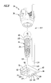
- Figur 7:
- eine Explosionsdarstellung des Pedikelschraubensystems aus Figur 1 mit Ausrichtinstrument; und
- Figur 8:
- eine weitere perspektivische Explosionsdarstellung des Pedikelschraubensystems aus
Figur 7 .
- FIG. 1:
- a schematic view of a spinal stabilization system comprising two bone screws and a connecting element which is fixed to a spinal column;
- FIG. 2:
- a side view of a screwed into a vertebra pedicle screw system;
- FIG. 3:
- another side view of the in
FIG. 2 illustrated pedicle screw system; - FIG. 4:
- a schematic perspective view of the pedicle screw system
FIG. 2 comprising a pedicle screw having bone alignment means coupled thereto; - FIG. 5:
- a side view of the pedicle screw system
FIG. 4 with cut bone alignment device and cut screw head; - FIG. 6:
- a further side view of the pedicle screw system of Figure 4 with cut bone alignment device and cut screw head;
- FIG. 7:
- an exploded view of the pedicle screw system of Figure 1 with alignment instrument; and
- FIG. 8:
- another perspective exploded view of the pedicle screw system
FIG. 7 ,
In
Selbstverständlich kann das Wirbelsäulenstabilisierungssystem 10 auch mehr als zwei Knochenschrauben 12 umfassen. Diese können beispielsweise über ein oder mehrere Verbindungselemente 14 miteinander verbunden werden.Of course, the
In
Bei den Knochenschrauben 12 kann es sich grundsätzlich um herkömmliche, am Markt verfügbare Pedikelschrauben handeln. Vorzugsweise ist mindestens eine der Knochenschrauben 12 jedoch in Form eines Pedikelschraubensystems 20 ausgebildet, welches nachfolgend im Einzelnen näher erläutert wird.The bone screws 12 may in principle be conventional pedicle screws available on the market. Preferably, however, at least one of the bone screws 12 is formed in the form of a
Jedes der Pedikelschraubensysteme 20 umfasst eine Pedikelschraube 24 mit einem Schraubenschaft 26, welcher ein Außengewinde 28 aufweist, beispielsweise in Form eines selbstschneidenden Knochengewindes, und einen kugelgelenkig am Schraubenschaft 26 gelagerten Schraubenkopf 30. Der Schraubenkopf 30 weist eine zwischen zwei freien Schenkeln 32 gebildete Verbindungselementaufnahme 34 für das Verbindungselement 14 des Wirbelsäulenstabilisierungssystems 10 auf.Each of the
An der Verbindungselementaufnahme 34 ist ferner ein Innengewinde 36 vorgesehen, welches korrespondierend zu einem Außengewinde 38 der Fixierschraube 22 ausgebildet ist, sodass die Fixierschraube zum Festlegen des Verbindungselements 14 ausgehend von freien Enden der Schenkel 32 in die Verbindungselementaufnahme 34 eingeschraubt werden kann, um das Verbindungselement 14 am Schraubenkopf 30 festzulegen.An
Zur Ausbildung eines Kugelgelenks 40 zwischen dem Schraubenschaft 26 und dem Schraubenkopf 30 ist ein proximales Ende des Schraubenschafts 26 in Form eines Gelenkkopfs 42 ausgebildet mit einer in proximaler Richtung weisenden ebenen Endfläche 44, an welche eine einen Teil einer Kugeloberfläche bildende Gelenkkopffläche 46 angrenzt. In proximaler Richtung weisend ist im Gelenkkopf 42 eine Werkzeugelementaufnahme 48 ausgebildet, beispielsweise in Form eines Innenvielkant oder eines Innenvielrund.To form a ball joint 40 between the
Am Schraubenkopf 30 ist eine Gelenkkopfaufnahme 50 ausgebildet in Form eines korrespondierend zum Gelenkkopf 42 ausgebildeten Sitzes 52, welcher in eine in distaler Richtung sich im Innendurchmesser verjüngende Durchbrechung 54 mündet, die an einem distalen Ende 56 des Schraubenkopfs 30 ausgebildet ist und aus der der Schraubenschaft 26 distalseitig des Gelenkkopfs 42 vorsteht.On the
Distalseitig schließt sich an den Gelenkkopf 42 ein gewindefreier Schaftabschnitt 58 an, welcher distalseitig von einem Ringflansch 60 begrenzt ist. Der Ringflansch 60 weist einen Außendurchmesser auf, der etwas größer ist als ein Außendurchmesser des Gelenkkopfs 42.On the distal end, a thread-
Das Pedikelschraubensystem 20 umfasst ferner eine Knochenausrichteinrichtung 62 und eine Kopplungseinrichtung 64 zum kraft- und/oder formschlüssigen Koppeln der Knochenausrichteinrichtung 62 und des Schraubenschafts 26 in einer Ausrichtstellung, wie sie beispielsweise in den
Die Knochenausrichteinrichtung 62 ist in Form einer Knochenplatte 66 ausgebildet, die eine ebene Oberseite 68 und konkavokonvex gekrümmte, vorzugsweise an eine Kontur eines Pedikels angepasste Unterseite 70 aufweist. Von der Unterseite der Knochenausrichteinrichtung 62 stehen mehrere Knochenverankerungselemente 72 ab, die in Form von dornenartigen Knochenpins 74 ausgebildet sind. Diese können optional auch widerhakenartige Verzahnungen aufweisen. Vorzugsweise sind die Knochenverankerungselemente 72 einstückig mit der Knochenplatte 66 ausgebildet.The
Zum Koppeln des Schraubenschafts 26 mit der Knochenausrichteinrichtung 62 umfasst die Kopplungseinrichtung 64 erste und zweite Kopplungselemente 76 und 78, die in der Ausrichtstellung kraft- und/oder formschlüssig in Eingriff stehen und einerseits an der Knochenausrichteinrichtung 62 und andererseits am Schraubenschaft 26 angeordnet oder ausgebildet sind.For coupling the
Das erste Kopplungselement 76 ist in Form eines Kopplungsvorsprungs 80 am Schraubenschaft 26 ausgebildet, das zweite Kopplungselement 78 in Form einer zum Kopplungsvorsprung 80 korrespondierenden Kopplungsaufnahme 82 an der Knochenausrichteinrichtung 62. Wie beispielsweise in den
Bei dem in den Figuren dargestellten Ausführungsbeispiel des Pedikelschraubensystems 20 ist der Kopplungsvorsprung 80 durch den Ringflansch 60 ausgebildet. Dieser kann insbesondere einstückig mit dem Schraubenschaft 26 ausgebildet sein. Alternativ kann der Kopplungsvorsprung 80 mit dem Schraubenschaft 26 auch kraft- und/oder stoffschlüssig verbunden sein, beispielsweise verpresst, verklebt, verlötet oder verschweißt.In the embodiment of the
Wie in den Figuren gut zu erkennen, ist der Kopplungsvorsprung 80 zwischen dem Außengewinde 28 und dem Gelenkkopf 42 angeordnet. Zudem ist ein Außendurchmesser 84 des Kopplungsvorsprungs 80 auch größer als ein maximaler Außendurchmesser 86 des Außengewindes 28.As can be clearly seen in the figures, the
Die Kopplungsaufnahme 82 ist in Form einer Ausnehmung 88 der Knochenausrichteinrichtung 62 ausgebildet.The
Die Knochenausrichteinrichtung 62 weist ferner eine Schraubenschaftaufnahme 90 auf, die der Schraubenschaft in der Ausrichtstellung durchsetzt. Sie ist in Form einer Durchbrechung 92 der Knochenplatte 66 ausgebildet. Die Kopplungsaufnahme 82 grenzt direkt an die Schraubenschaftaufnahme 90 an.The
Ein Innendurchmesser 94 der Kopplungsaufnahme 82 ist größer als ein Innendurchmesser der Schraubenschaftaufnahme 90. Durch diese Wahl der Abmessungen der Kopplungsaufnahme 82 und der Schraubenschaftaufnahme 90 wird eine sich einstufig in distaler Richtung verjüngende Durchbrechung ausgebildet, die eine in proximaler Richtung weisende, die Kopplungsaufnahme 82 teilweise begrenzende Ringfläche 98 definiert, an welcher eine in distaler Richtung weisende Ringfläche 100 des Ringflanschs 60 in der Ausrichtstellung anliegt beziehungsweise anschlägt.An
Bei dem in den Figuren dargestellten Ausführungsbeispiel definiert die Kopplungseinrichtung 64 eine Längsachse 102, welche parallel zu einer Schraubenschaftlängsachse 104 des Schraubenschafts 26 verläuft beziehungsweise mit dieser zusammenfällt.In the exemplary embodiment illustrated in the figures, the
Alternativ ist es auch denkbar, eine Längsachse der Kopplungseinrichtung 64, die beispielsweise vorgegeben ist durch eine Längsachse 106 der Schraubenschaftaufnahme 90, relativ zu einer Längsachse 108, die durch die Kopplungsaufnahme 82 vorgegeben ist, um einen Neigungswinkel 110 geneigt auszubilden. Der Neigungswinkel 110 kann beispielsweise einen Wert in einem Bereich von etwa 0° bis etwa 30° aufweisen.Alternatively, it is also conceivable, a longitudinal axis of the
Ferner umfasst die Knochenausrichteinrichtung 62 vorzugsweise mindestens eine Kupplungseinrichtung 112 zum temporären kraft- und/oder formschlüssigen Kuppeln mit einem Ausrichtinstrument 114 in einer beispielsweise in den
Die Kupplungseinrichtung 112 umfasst mindestens ein Kupplungselement 116 zum kraft- und/oder formschlüssigen Kuppeln mit dem Ausrichtinstrument 114 in der Kuppelstellung. Das Kupplungselement 116 kann insbesondere in Form eines Kupplungsvorsprungs oder, wie in den Figuren beispielhaft dargestellt, in Form einer Kupplungsausnehmung 118 ausgebildet sein. Ferner ist es alternativ auch möglich, sowohl einen Kupplungsvorsprung als auch eine Kupplungsausnehmung an der Knochenausrichteinrichtung 62 vorzusehen.The
Die Kupplungsausnehmung 118 ist bei dem in den Figuren dargestellten Ausführungsbeispiel in Form einer Durchbrechung 120 der Knochenplatte 66 ausgebildet. Alternativ ist es möglich, die Kupplungsausnehmung 118 auch in Form eines Sacklochs auszubilden. Vorzugsweise wird die Durchbrechung 120 in Form einer Bohrung 122 ausgebildet.The
Um eine einfache und sichere Verbindung zwischen dem Ausrichtinstrument 114 und der Knochenausrichteinrichtung 62 zu realisieren, ist ausgehend von einem distalen Ende 124 des Ausrichtinstruments 114 ein Kupplungsende 128 zum kraft- und/oder formschlüssigen Kuppeln mit der Kupplungseinrichtung 112 der Knochenausrichteinrichtung 62 ausgebildet. Hierfür kann das Kupplungselement 116, welches in Form der Bohrung 122 ausgebildet ist, ferner mit einem Gewinde 130, insbesondere einem Innengewinde 132, versehen oder in Form eines Rastelements ausgebildet sein. Das Kupplungsende 128 ist dann vorzugsweise korrespondierend zur Kupplungseinrichtung 112 ausgebildet, also beispielsweise ebenfalls in Form eines Rastelements oder ein Gewinde 134 in Form eines Außengewindes 136 umfassend.In order to realize a simple and secure connection between the
Die Funktionsweise des Wirbelsäulenstabilisierungssystems 10 sowie dessen Pedikelschraubensysteme 20 wird nachfolgend erläutert.The operation of the
Zum Einbringen der Pedikelschraube 24 in den Wirbel 16 wird mit einem in den Figuren nicht dargestellten Einschraubinstrument, welches ein zur Werkzeugelementaufnahme 48 korrespondierendes Werkzeugende aufweist, der Schraubenschaft 26 in den Wirbel 16 eingeschraubt. Hierfür kann der Wirbel vorab angebohrt oder anderweitig mit einer Führungsöffnung versehen werden.For introducing the
Vor dem Einschrauben kann die Knochenausrichteinrichtung 62 bereits mit dem Schraubenschaft 26 gekoppelt werden, sodass der Schraubenschaft 26 und die Knochenausrichteinrichtung 62 bereits die Ausrichtstellung einnehmen. Denkbar ist es alternativ, die Knochenplatte 66 an einer gewünschten Stelle des Wirbels 16 anzubringen, beispielsweise durch Einschlagen der Knochenverankerungselemente 72 in den Wirbel 16. Der Schraubenschaft 26 kann dann durch die Kopplungsaufnahme 82 und die Schraubenschaftaufnahme 90 hindurch in den Wirbel 16 eingeschraubt werden, bis der Ringflansch 60 an der Ringfläche 98 der Kopplungsaufnahme 82 anschlägt.Before screwing in, the
Um eine sichere Orientierung und Befestigung der Pedikelschraube 24 am Wirbel 16 zu erreichen, kann optional bereits beim Einschrauben der Pedikelschraube 24 das Ausrichtinstrument 114 mit der Knochenplatte 66 in der oben beschriebenen Weise verbunden werden, indem das Kupplungsende 128 und die Kupplungseinrichtung 112 kraft- und/oder formschlüssig miteinander in Eingriff gebracht werden. Ein Operateur kann so ein proximales Ende des Ausrichtinstruments 114, welches vorzugsweise in Form eines Griffelements 138 ausgebildet ist, erfassen und damit die Knochenplatte 66 in einer gewünschten Orientierung ausrichten und in dieser halten.In order to achieve a secure orientation and fastening of the
Ist die Pedikelschraube 24, wie beispielhaft in den
In der beschriebenen Weise kann jede der Pedikelschrauben 24 mit einem Ausrichtinstrument 114 gekoppelt und gleichzeitig bewegt werden.In the manner described, each of the pedicle screws 24 can be coupled to an
Dadurch, dass die Schraubenköpfe 30 und die Schraubenschäfte 26 über das Kugelgelenk 40 miteinander kugelgelenkig gekoppelt sind, kann das Verbindungselement 14 anschließend auf einfache Weise in die Verbindungselementaufnahmen 34 eingesetzt und mit den Fixierschrauben festgelegt werden. Die Schraubenköpfe 30 können nämlich um einen Mittelpunkt des Gelenkkopfs 42 relativ zu den Schraubenschäften 26 verschwenkt und so ausgerichtet werden, dass beispielsweise ein stabförmiges Verbindungselement 14 ohne weitere Verformung der Pedikelschrauben 24 in die Verbindungselementaufnahmen 34 eingelegt werden kann.Characterized in that the screw heads 30 and the
Das vorgeschlagene Pedikelschraubensystem 20 vereint somit die Vorteile einer Polyaxialschraube einerseits und andererseits eine mögliche Manipulationsmöglichkeit von Wirbeln, in die die Pedikelschraube eingeschraubt ist, wie sie insbesondere bei Pedikelschrauben mit unbeweglich am Schraubenschaft angeordneten Schraubenköpfen oder bei Monoaxialschrauben der Fall ist, miteinander.The proposed
- 1010
- WirbelsäulenstabilisierungssystemSpine stabilization system
- 1212
- Knochenschraubebone screw
- 1414
- Verbindungselementconnecting element
- 1616
- Wirbelwhirl
- 1818
- Wirbelsäulespinal column
- 2020
- Pedikelschraubensystempedicle screw system
- 2222
- Fixierschraubefixing screw
- 2424
- Pedikelschraubepedicle screw
- 2626
- Schraubenschaftscrew shaft
- 2828
- Außengewindeexternal thread
- 3030
- Schraubenkopfscrew head
- 3232
- Schenkelleg
- 3434
- VerbindungselementaufnahmeConnecting element receptacle
- 3636
- Innengewindeinner thread
- 3838
- Außengewindeexternal thread
- 4040
- Kugelgelenkball joint
- 4242
- Gelenkkopfjoint head
- 4444
- Endflächeend face
- 4646
- GelenkkopfflächeCondyle surface
- 4848
- WerkzeugelementaufnahmeTool element receiver
- 5050
- GelenkkopfaufnahmeJoint head receptacle
- 5252
- SitzSeat
- 5454
- Durchbrechungperforation
- 5656
- EndeThe End
- 5858
- Schaftabschnittshank portion
- 6060
- Ringflanschannular flange
- 6262
- KnochenausrichteinrichtungKnochenausrichteinrichtung
- 6464
- Kopplungseinrichtungcoupling device
- 6666
- Knochenplattebone plate
- 6868
- Oberseitetop
- 7070
- Unterseitebottom
- 7272
- KnochenverankerungselementBone anchoring element
- 7474
- Knochenpinbone pin
- 7676
- erstes Kopplungselementfirst coupling element
- 7878
- zweites Kopplungselementsecond coupling element
- 8080
- Kopplungsvorsprungcoupling projection
- 8282
- Kopplungsaufnahmefemale coupling
- 8484
- Außendurchmesserouter diameter
- 8686
- Außendurchmesserouter diameter
- 8888
- Ausnehmungrecess
- 9090
- SchraubenschaftaufnahmeScrew shaft receiver
- 9292
- Durchbrechungperforation
- 9494
- InnendurchmesserInner diameter
- 9696
- InnendurchmesserInner diameter
- 9898
- Ringflächering surface
- 100100
- Ringflächering surface
- 102102
- Längsachselongitudinal axis
- 104104
- SchraubenschaftlängsachseScrew shaft longitudinal axis
- 106106
- Längsachselongitudinal axis
- 108108
- Längsachselongitudinal axis
- 110110
- Neigungswinkeltilt angle
- 112112
- Kupplungseinrichtungcoupling device
- 114114
- Ausrichtinstrumentalignment instrument
- 116116
- Kupplungselementcoupling member
- 118118
- Kupplungsausnehmungcoupling recess
- 120120
- Durchbrechungperforation
- 122122
- Bohrungdrilling
- 124124
- EndeThe End
- 128128
- Kupplungsendecoupling end
- 130130
- Gewindethread
- 132132
- Innengewindeinner thread
- 134134
- Gewindethread
- 136136
- Außengewindeexternal thread
- 138138
- Griffelementhandle element
Claims (15)
dadurch gekennzeichnet, dass die Kopplungseinrichtung (64) erste und zweite Kopplungselemente (76, 78) umfasst, welche in der Ausrichtstellung kraft- und/oder formschlüssig in Eingriff stehen und einerseits an der Knochenausrichteinrichtung (62) und andererseits am Schraubenschaft (26) angeordnet oder ausgebildet sind.Pedicle screw system according to one of the preceding claims,
characterized in that the coupling device (64) comprises first and second coupling elements (76, 78), which are non-positively and / or positively engaged in the alignment position and arranged on the one hand on the Knochenausrichteinrichtung (62) and on the other hand on the screw shank (26) or are formed.
dass der Kopplungsvorsprung (80) einstückig mit dem Schraubenschaft (26) ausgebildet oder kraft- und/oder stoffschlüssig mit dem Schraubenschaft (26) verbunden ist, insbesondere verpresst, verklebt, verlötet oder verschweißt,
und/oder
dass der Kopplungsvorsprung (80) in Form eines Ringflansches (60) ausgebildet ist
und/oder
dass der Schraubenschaft (26) einen Gelenkkopf (42) aufweist und dass der Schraubenkopf (30) eine zum Gelenkkopf (42) korrespondierende Gelenkkopfaufnahme (50) zur Ausbildung eines Kugelgelenks (40) im Zusammenwirken mit dem Gelenkkopf (42) aufweist.Pedicle screw system according to claim 4, characterized in that the coupling projection (80) in the alignment position positively or engages substantially positively in the coupling receptacle (82) and / or
in that the coupling projection (80) is formed integrally with the screw shank (26) or is connected to the screw shank (26) in a non-positive and / or materially bonded manner, in particular pressed, glued, soldered or welded,
and or
in that the coupling projection (80) is designed in the form of an annular flange (60)
and or
in that the screw shaft (26) has a condyle (42) and that the screw head (30) has a condyle (50) corresponding to the condyle (42) for forming a ball joint (40) in cooperation with the condyle (42).
dadurch gekennzeichnet, dass die Kopplungseinrichtung (64) eine Längsachse (102) definiert, welche parallel zu einer Schraubenschaftlängsachse (104) des Schraubenschafts (26) verläuft oder mit dieser einen Neigungswinkel (110) einschließt.Pedicle screw system according to one of the preceding claims,
characterized in that the coupling means (64) defining a longitudinal axis (102) which is parallel to a screw shaft longitudinal axis (104) of the screw shaft (26) or with this includes an inclination angle (110).
dadurch gekennzeichnet, dass die Knochenausrichteinrichtung (62) mindestens eine Kupplungseinrichtung (112) zum temporären kraft- und/oder formschlüssigen Kuppeln mit einem Ausrichtinstrument (114) in einer Kuppelstellung aufweist.Pedicle screw system according to one of the preceding claims,
characterized in that the bone alignment device (62) has at least one coupling device (112) for temporary non-positive and / or positive coupling with an alignment instrument (114) in a coupling position.
Applications Claiming Priority (1)
| Application Number | Priority Date | Filing Date | Title |
|---|---|---|---|
| DE102014117175.6A DE102014117175A1 (en) | 2014-11-24 | 2014-11-24 | Pedicle screw system and spine stabilization system |
Publications (3)
| Publication Number | Publication Date |
|---|---|
| EP3023066A1 true EP3023066A1 (en) | 2016-05-25 |
| EP3023066B1 EP3023066B1 (en) | 2020-02-26 |
| EP3023066B8 EP3023066B8 (en) | 2020-04-08 |
Family
ID=54703813
Family Applications (1)
| Application Number | Title | Priority Date | Filing Date |
|---|---|---|---|
| EP15195766.9A Active EP3023066B8 (en) | 2014-11-24 | 2015-11-23 | Pedicle screw system and spinal column-stabilizing system |
Country Status (4)
| Country | Link |
|---|---|
| US (1) | US9848915B2 (en) |
| EP (1) | EP3023066B8 (en) |
| DE (1) | DE102014117175A1 (en) |
| ES (1) | ES2781855T3 (en) |
Families Citing this family (5)
| Publication number | Priority date | Publication date | Assignee | Title |
|---|---|---|---|---|
| US9585697B2 (en) * | 2011-04-01 | 2017-03-07 | Rebecca Elizabeth Stachniak | Posterior stabilization systems and methods |
| US9918763B2 (en) * | 2015-07-24 | 2018-03-20 | Warsaw Orthopedic, Inc. | Bone fixation element and methods of use |
| EP3490472B1 (en) | 2016-07-29 | 2021-06-02 | Zimmer Biomet Spine, Inc. | Bone screw threaded enlarger |
| US12082848B2 (en) * | 2019-02-27 | 2024-09-10 | Orthopediatrics Corp. | Bone anchors with cord retention features |
| US12082849B2 (en) * | 2019-04-12 | 2024-09-10 | Orthopediatrics Corp. | Dual tether support of vertebra |
Citations (6)
| Publication number | Priority date | Publication date | Assignee | Title |
|---|---|---|---|---|
| FR2761876A1 (en) * | 1997-04-09 | 1998-10-16 | Materiel Orthopedique En Abreg | INSTRUMENTATION OF LUMBAR OSTEOSYNTHESIS FOR CORRECTION OF SPONDYLOLISTHESIS BY POSTERIOR PATHWAY |
| US20080086131A1 (en) * | 2006-10-06 | 2008-04-10 | Depuy Spine, Inc. | Bone screw fixation |
| DE102006055599A1 (en) * | 2006-11-24 | 2008-06-05 | Peter Brehm | Orthopedic fastening device and device for correcting spinal deformity |
| US20100305616A1 (en) * | 2008-01-14 | 2010-12-02 | John Carbone | Spinal fixation device and method |
| US20130030474A1 (en) * | 2011-07-26 | 2013-01-31 | Christopher Chaput | Bone Screws and Bone Screw Systems |
| DE102013100574A1 (en) | 2013-01-21 | 2014-07-24 | Aesculap Ag | Implant system and fastener for an implant system |
Family Cites Families (50)
| Publication number | Priority date | Publication date | Assignee | Title |
|---|---|---|---|---|
| GB1551705A (en) * | 1975-04-28 | 1979-08-30 | Downs Surgicial Ltd | Surgial implant |
| FR2651992B1 (en) * | 1989-09-18 | 1991-12-13 | Sofamor | IMPLANT FOR ANTERIOR DORSO-LUMBAR SPINE OSTEOSYNTHESIS FOR CORRECTION OF CYPHOSIS. |
| US5306275A (en) * | 1992-12-31 | 1994-04-26 | Bryan Donald W | Lumbar spine fixation apparatus and method |
| SE9402130D0 (en) * | 1994-06-17 | 1994-06-17 | Sven Olerud | Device and method for plate fixation of legs |
| US5620443A (en) * | 1995-01-25 | 1997-04-15 | Danek Medical, Inc. | Anterior screw-rod connector |
| US5843082A (en) * | 1996-05-31 | 1998-12-01 | Acromed Corporation | Cervical spine stabilization method and system |
| US5849004A (en) * | 1996-07-17 | 1998-12-15 | Bramlet; Dale G. | Surgical anchor |
| US6139550A (en) * | 1997-02-11 | 2000-10-31 | Michelson; Gary K. | Skeletal plating system |
| US6454769B2 (en) * | 1997-08-04 | 2002-09-24 | Spinal Concepts, Inc. | System and method for stabilizing the human spine with a bone plate |
| US5899904A (en) * | 1998-10-19 | 1999-05-04 | Third Milennium Engineering, Llc | Compression locking vertebral body screw, staple, and rod assembly |
| US5947969A (en) * | 1998-10-19 | 1999-09-07 | Third Millennium Engineering, Llc | Rotatable locking vertebral body screw, staple and rod assembly |
| DE19848715C1 (en) | 1998-10-22 | 2000-08-24 | Aesculap Ag & Co Kg | Osteo-synthetic holding system has locking units for the holding rods of different dimensions for the holding rods to allow adjustments to the setting of the bones or fragments before final clamping |
| FR2810532B1 (en) * | 2000-06-26 | 2003-05-30 | Stryker Spine Sa | BONE IMPLANT WITH ANNULAR LOCKING MEANS |
| US6533787B1 (en) * | 2000-07-31 | 2003-03-18 | Sdgi Holdings, Inc. | Contourable spinal staple with centralized and unilateral prongs |
| US7766947B2 (en) * | 2001-10-31 | 2010-08-03 | Ortho Development Corporation | Cervical plate for stabilizing the human spine |
| US20040019353A1 (en) * | 2002-02-01 | 2004-01-29 | Freid James M. | Spinal plate system for stabilizing a portion of a spine |
| US7175623B2 (en) * | 2002-06-24 | 2007-02-13 | Lanx, Llc | Cervical plate with backout protection |
| US7273481B2 (en) * | 2002-10-28 | 2007-09-25 | Blackstone Medical, Inc. | Bone plate assembly provided with screw locking mechanisms |
| EP2366349B1 (en) * | 2002-10-30 | 2017-04-05 | Zimmer Spine, Inc. | Spinal stabilization system insertion |
| US7524325B2 (en) * | 2002-11-04 | 2009-04-28 | Farid Bruce Khalili | Fastener retention system |
| FR2848413B1 (en) * | 2002-12-11 | 2005-07-29 | Fixano | OSTEOSYNTHESIS PLATE FOR OSTEOSYNTHESIS OF SMALL BONE NEIGHBORS OF OTHERS |
| FR2848408B1 (en) * | 2002-12-17 | 2005-08-19 | Vitatech | DEVICE WITH ANTERIOR PLATE FOR MAINTAINING THE RACHIS |
| US20040181227A1 (en) * | 2003-03-11 | 2004-09-16 | Farid Khalili | System and method for attaching a bone plate to bone |
| US7473267B2 (en) * | 2003-04-25 | 2009-01-06 | Warsaw Orthopedic, Inc. | System and method for minimally invasive posterior fixation |
| US6945975B2 (en) * | 2003-07-07 | 2005-09-20 | Aesculap, Inc. | Bone fixation assembly and method of securement |
| US7857839B2 (en) * | 2003-09-03 | 2010-12-28 | Synthes Usa, Llc | Bone plate with captive clips |
| US7909860B2 (en) * | 2003-09-03 | 2011-03-22 | Synthes Usa, Llc | Bone plate with captive clips |
| US7588588B2 (en) * | 2003-10-21 | 2009-09-15 | Innovative Spinal Technologies | System and method for stabilizing of internal structures |
| CA2449883A1 (en) * | 2003-11-18 | 2005-05-18 | Terray Corporation | Taper-lock bone screw fixation system |
| US7195633B2 (en) * | 2004-01-08 | 2007-03-27 | Robert J. Medoff | Fracture fixation system |
| US7740649B2 (en) * | 2004-02-26 | 2010-06-22 | Pioneer Surgical Technology, Inc. | Bone plate system and methods |
| US7615069B2 (en) * | 2004-04-08 | 2009-11-10 | Globus Medical, Inc. | Load distribution crown |
| US20050277937A1 (en) * | 2004-06-10 | 2005-12-15 | Leung Takkwong R | Bone plating system |
| US7883510B2 (en) * | 2004-08-27 | 2011-02-08 | Depuy Spine, Inc. | Vertebral staples and insertion tools |
| US7935137B2 (en) * | 2004-12-08 | 2011-05-03 | Depuy Spine, Inc. | Locking bone screw and spinal plate system |
| US7931678B2 (en) * | 2004-12-08 | 2011-04-26 | Depuy Spine, Inc. | Hybrid spinal plates |
| US7951172B2 (en) * | 2005-03-04 | 2011-05-31 | Depuy Spine Sarl | Constrained motion bone screw assembly |
| US8414616B2 (en) * | 2006-09-12 | 2013-04-09 | Pioneer Surgical Technology, Inc. | Mounting devices for fixation devices and insertion instruments used therewith |
| US20090062914A1 (en) * | 2007-08-29 | 2009-03-05 | Marino James F | Devices and methods for intervertebral therapy |
| US8282675B2 (en) * | 2008-01-25 | 2012-10-09 | Depuy Spine, Inc. | Anti-backout mechanism |
| US9504494B2 (en) * | 2008-04-28 | 2016-11-29 | DePuy Synthes Products, Inc. | Implants for securing spinal fixation elements |
| EP2135562B1 (en) * | 2008-06-20 | 2015-09-09 | Arthrex, Inc. | Wedged profile plate |
| US8419778B2 (en) | 2010-01-15 | 2013-04-16 | Ebi, Llc | Uniplanar bone anchor system |
| CA2810978A1 (en) * | 2010-09-08 | 2012-03-15 | Roger P. Jackson | Dynamic stabilization members with elastic and inelastic sections |
| US8337532B1 (en) * | 2011-12-08 | 2012-12-25 | Spine Wave, Inc. | Methods for percutaneously extending an existing spinal construct |
| EP2604204B1 (en) | 2011-12-13 | 2014-10-01 | Biedermann Technologies GmbH & Co. KG | Monoplanar bone anchoring device with selectable pivot plane |
| US8470009B1 (en) | 2012-03-08 | 2013-06-25 | Warsaw Orthopedic, Inc. | Bone fastener and method of use |
| US9060815B1 (en) * | 2012-03-08 | 2015-06-23 | Nuvasive, Inc. | Systems and methods for performing spine surgery |
| DE102012219630A1 (en) * | 2012-10-26 | 2014-04-30 | Premiere Medical Gmbh | Bone screw, head housing for a bone screw and reduction instrument |
| US9517089B1 (en) * | 2013-10-08 | 2016-12-13 | Nuvasive, Inc. | Bone anchor with offset rod connector |
-
2014
- 2014-11-24 DE DE102014117175.6A patent/DE102014117175A1/en not_active Withdrawn
-
2015
- 2015-11-23 ES ES15195766T patent/ES2781855T3/en active Active
- 2015-11-23 US US14/948,840 patent/US9848915B2/en active Active
- 2015-11-23 EP EP15195766.9A patent/EP3023066B8/en active Active
Patent Citations (6)
| Publication number | Priority date | Publication date | Assignee | Title |
|---|---|---|---|---|
| FR2761876A1 (en) * | 1997-04-09 | 1998-10-16 | Materiel Orthopedique En Abreg | INSTRUMENTATION OF LUMBAR OSTEOSYNTHESIS FOR CORRECTION OF SPONDYLOLISTHESIS BY POSTERIOR PATHWAY |
| US20080086131A1 (en) * | 2006-10-06 | 2008-04-10 | Depuy Spine, Inc. | Bone screw fixation |
| DE102006055599A1 (en) * | 2006-11-24 | 2008-06-05 | Peter Brehm | Orthopedic fastening device and device for correcting spinal deformity |
| US20100305616A1 (en) * | 2008-01-14 | 2010-12-02 | John Carbone | Spinal fixation device and method |
| US20130030474A1 (en) * | 2011-07-26 | 2013-01-31 | Christopher Chaput | Bone Screws and Bone Screw Systems |
| DE102013100574A1 (en) | 2013-01-21 | 2014-07-24 | Aesculap Ag | Implant system and fastener for an implant system |
Also Published As
| Publication number | Publication date |
|---|---|
| US20160143667A1 (en) | 2016-05-26 |
| ES2781855T3 (en) | 2020-09-08 |
| EP3023066B1 (en) | 2020-02-26 |
| EP3023066B8 (en) | 2020-04-08 |
| DE102014117175A1 (en) | 2016-05-25 |
| US9848915B2 (en) | 2017-12-26 |
Similar Documents
| Publication | Publication Date | Title |
|---|---|---|
| EP2692304B1 (en) | Set of surgical instruments | |
| EP3454767B1 (en) | Medical instrument for provisionally fastening a polyaxial pedicle screw | |
| EP3954312B1 (en) | Surgical instrument | |
| EP3117787B1 (en) | Pedicle screw with tulip | |
| EP3023065B1 (en) | Pedicle screw system and spinal column-stabilizing system | |
| DE69723108T2 (en) | ADJUSTABLE OSTEOSYNTHESIS DEVICE FOR THE SPINE AND POSITIONING TOOL | |
| EP2266483B1 (en) | Surgical bone anchoring device and spinal column fixation system | |
| DE102004027881B4 (en) | Bone screw and osteosynthesis device | |
| DE60023323T2 (en) | Multi-axis bone screw arrangement | |
| DE69124293T2 (en) | Device for the treatment of spinal diseases | |
| EP2976031B1 (en) | Vertebral column-stabilizing system and surgical fastening element for a vertebral column-stabilizing system | |
| DE102005009282A1 (en) | Fixing element for a bone implant system comprises a fixing part with a fixing section on the distal side and a receiving part connected to the fixing part | |
| EP3023066B1 (en) | Pedicle screw system and spinal column-stabilizing system | |
| EP1392190B1 (en) | Manipulator for handling a pedicule screw | |
| EP3383291B1 (en) | Medical instrument and medical equipment | |
| DE102014109935A1 (en) | Positioning device for fixing an intramedullary nail in a long bone | |
| EP1269929A1 (en) | Connection system for the spinal fusion of the lumbar column | |
| DE10005134B4 (en) | Grafting system for spinal fusion of the lumbar spine and pedicle screw and anvil for use in such | |
| EP1269927B1 (en) | Connection system for the spinal fusion of the lumbar column | |
| DE10005133B4 (en) | Grafting system for spinal fusion of the lumbar spine | |
| DE102022108980A1 (en) | Osteosynthesis device, in particular for treating the spine, and fastening system for the same | |
| DE102014100362A1 (en) | Medical instrument, medical instrumentation and spine stabilization system |
Legal Events
| Date | Code | Title | Description |
|---|---|---|---|
| AK | Designated contracting states |
Kind code of ref document: A1 Designated state(s): AL AT BE BG CH CY CZ DE DK EE ES FI FR GB GR HR HU IE IS IT LI LT LU LV MC MK MT NL NO PL PT RO RS SE SI SK SM TR |
|
| AX | Request for extension of the european patent |
Extension state: BA ME |
|
| PUAI | Public reference made under article 153(3) epc to a published international application that has entered the european phase |
Free format text: ORIGINAL CODE: 0009012 |
|
| STAA | Information on the status of an ep patent application or granted ep patent |
Free format text: STATUS: REQUEST FOR EXAMINATION WAS MADE |
|
| 17P | Request for examination filed |
Effective date: 20161125 |
|
| RBV | Designated contracting states (corrected) |
Designated state(s): AL AT BE BG CH CY CZ DE DK EE ES FI FR GB GR HR HU IE IS IT LI LT LU LV MC MK MT NL NO PL PT RO RS SE SI SK SM TR |
|
| GRAP | Despatch of communication of intention to grant a patent |
Free format text: ORIGINAL CODE: EPIDOSNIGR1 |
|
| STAA | Information on the status of an ep patent application or granted ep patent |
Free format text: STATUS: GRANT OF PATENT IS INTENDED |
|
| RIC1 | Information provided on ipc code assigned before grant |
Ipc: A61B 17/70 20060101AFI20190802BHEP |
|
| INTG | Intention to grant announced |
Effective date: 20190826 |
|
| GRAJ | Information related to disapproval of communication of intention to grant by the applicant or resumption of examination proceedings by the epo deleted |
Free format text: ORIGINAL CODE: EPIDOSDIGR1 |
|
| STAA | Information on the status of an ep patent application or granted ep patent |
Free format text: STATUS: REQUEST FOR EXAMINATION WAS MADE |
|
| GRAP | Despatch of communication of intention to grant a patent |
Free format text: ORIGINAL CODE: EPIDOSNIGR1 |
|
| STAA | Information on the status of an ep patent application or granted ep patent |
Free format text: STATUS: GRANT OF PATENT IS INTENDED |
|
| GRAJ | Information related to disapproval of communication of intention to grant by the applicant or resumption of examination proceedings by the epo deleted |
Free format text: ORIGINAL CODE: EPIDOSDIGR1 |
|
| STAA | Information on the status of an ep patent application or granted ep patent |
Free format text: STATUS: REQUEST FOR EXAMINATION WAS MADE |
|
| INTC | Intention to grant announced (deleted) | ||
| INTG | Intention to grant announced |
Effective date: 20191216 |
|
| GRAP | Despatch of communication of intention to grant a patent |
Free format text: ORIGINAL CODE: EPIDOSNIGR1 |
|
| STAA | Information on the status of an ep patent application or granted ep patent |
Free format text: STATUS: GRANT OF PATENT IS INTENDED |
|
| GRAS | Grant fee paid |
Free format text: ORIGINAL CODE: EPIDOSNIGR3 |
|
| GRAA | (expected) grant |
Free format text: ORIGINAL CODE: 0009210 |
|
| STAA | Information on the status of an ep patent application or granted ep patent |
Free format text: STATUS: THE PATENT HAS BEEN GRANTED |
|
| INTC | Intention to grant announced (deleted) | ||
| INTG | Intention to grant announced |
Effective date: 20200117 |
|
| GRAT | Correction requested after decision to grant or after decision to maintain patent in amended form |
Free format text: ORIGINAL CODE: EPIDOSNCDEC |
|
| AK | Designated contracting states |
Kind code of ref document: B1 Designated state(s): AL AT BE BG CH CY CZ DE DK EE ES FI FR GB GR HR HU IE IS IT LI LT LU LV MC MK MT NL NO PL PT RO RS SE SI SK SM TR |
|
| REG | Reference to a national code |
Ref country code: GB Ref legal event code: FG4D Free format text: NOT ENGLISH |
|
| REG | Reference to a national code |
Ref country code: CH Ref legal event code: EP |
|
| REG | Reference to a national code |
Ref country code: DE Ref legal event code: R096 Ref document number: 502015011841 Country of ref document: DE |
|
| REG | Reference to a national code |
Ref country code: CH Ref legal event code: PK Free format text: BERICHTIGUNG B8 |
|
| REG | Reference to a national code |
Ref country code: AT Ref legal event code: REF Ref document number: 1236704 Country of ref document: AT Kind code of ref document: T Effective date: 20200315 |
|
| RAP2 | Party data changed (patent owner data changed or rights of a patent transferred) |
Owner name: AESCULAP AG |
|
| REG | Reference to a national code |
Ref country code: IE Ref legal event code: FG4D Free format text: LANGUAGE OF EP DOCUMENT: GERMAN |
|
| PG25 | Lapsed in a contracting state [announced via postgrant information from national office to epo] |
Ref country code: RS Free format text: LAPSE BECAUSE OF FAILURE TO SUBMIT A TRANSLATION OF THE DESCRIPTION OR TO PAY THE FEE WITHIN THE PRESCRIBED TIME-LIMIT Effective date: 20200226 Ref country code: NO Free format text: LAPSE BECAUSE OF FAILURE TO SUBMIT A TRANSLATION OF THE DESCRIPTION OR TO PAY THE FEE WITHIN THE PRESCRIBED TIME-LIMIT Effective date: 20200526 Ref country code: FI Free format text: LAPSE BECAUSE OF FAILURE TO SUBMIT A TRANSLATION OF THE DESCRIPTION OR TO PAY THE FEE WITHIN THE PRESCRIBED TIME-LIMIT Effective date: 20200226 |
|
| REG | Reference to a national code |
Ref country code: NL Ref legal event code: MP Effective date: 20200226 |
|
| REG | Reference to a national code |
Ref country code: LT Ref legal event code: MG4D |
|
| PG25 | Lapsed in a contracting state [announced via postgrant information from national office to epo] |
Ref country code: IS Free format text: LAPSE BECAUSE OF FAILURE TO SUBMIT A TRANSLATION OF THE DESCRIPTION OR TO PAY THE FEE WITHIN THE PRESCRIBED TIME-LIMIT Effective date: 20200626 Ref country code: BG Free format text: LAPSE BECAUSE OF FAILURE TO SUBMIT A TRANSLATION OF THE DESCRIPTION OR TO PAY THE FEE WITHIN THE PRESCRIBED TIME-LIMIT Effective date: 20200526 Ref country code: HR Free format text: LAPSE BECAUSE OF FAILURE TO SUBMIT A TRANSLATION OF THE DESCRIPTION OR TO PAY THE FEE WITHIN THE PRESCRIBED TIME-LIMIT Effective date: 20200226 Ref country code: GR Free format text: LAPSE BECAUSE OF FAILURE TO SUBMIT A TRANSLATION OF THE DESCRIPTION OR TO PAY THE FEE WITHIN THE PRESCRIBED TIME-LIMIT Effective date: 20200527 Ref country code: SE Free format text: LAPSE BECAUSE OF FAILURE TO SUBMIT A TRANSLATION OF THE DESCRIPTION OR TO PAY THE FEE WITHIN THE PRESCRIBED TIME-LIMIT Effective date: 20200226 Ref country code: LV Free format text: LAPSE BECAUSE OF FAILURE TO SUBMIT A TRANSLATION OF THE DESCRIPTION OR TO PAY THE FEE WITHIN THE PRESCRIBED TIME-LIMIT Effective date: 20200226 |
|
| REG | Reference to a national code |
Ref country code: ES Ref legal event code: FG2A Ref document number: 2781855 Country of ref document: ES Kind code of ref document: T3 Effective date: 20200908 |
|
| PG25 | Lapsed in a contracting state [announced via postgrant information from national office to epo] |
Ref country code: NL Free format text: LAPSE BECAUSE OF FAILURE TO SUBMIT A TRANSLATION OF THE DESCRIPTION OR TO PAY THE FEE WITHIN THE PRESCRIBED TIME-LIMIT Effective date: 20200226 |
|
| PG25 | Lapsed in a contracting state [announced via postgrant information from national office to epo] |
Ref country code: EE Free format text: LAPSE BECAUSE OF FAILURE TO SUBMIT A TRANSLATION OF THE DESCRIPTION OR TO PAY THE FEE WITHIN THE PRESCRIBED TIME-LIMIT Effective date: 20200226 Ref country code: LT Free format text: LAPSE BECAUSE OF FAILURE TO SUBMIT A TRANSLATION OF THE DESCRIPTION OR TO PAY THE FEE WITHIN THE PRESCRIBED TIME-LIMIT Effective date: 20200226 Ref country code: DK Free format text: LAPSE BECAUSE OF FAILURE TO SUBMIT A TRANSLATION OF THE DESCRIPTION OR TO PAY THE FEE WITHIN THE PRESCRIBED TIME-LIMIT Effective date: 20200226 Ref country code: SM Free format text: LAPSE BECAUSE OF FAILURE TO SUBMIT A TRANSLATION OF THE DESCRIPTION OR TO PAY THE FEE WITHIN THE PRESCRIBED TIME-LIMIT Effective date: 20200226 Ref country code: SK Free format text: LAPSE BECAUSE OF FAILURE TO SUBMIT A TRANSLATION OF THE DESCRIPTION OR TO PAY THE FEE WITHIN THE PRESCRIBED TIME-LIMIT Effective date: 20200226 Ref country code: PT Free format text: LAPSE BECAUSE OF FAILURE TO SUBMIT A TRANSLATION OF THE DESCRIPTION OR TO PAY THE FEE WITHIN THE PRESCRIBED TIME-LIMIT Effective date: 20200719 Ref country code: CZ Free format text: LAPSE BECAUSE OF FAILURE TO SUBMIT A TRANSLATION OF THE DESCRIPTION OR TO PAY THE FEE WITHIN THE PRESCRIBED TIME-LIMIT Effective date: 20200226 Ref country code: RO Free format text: LAPSE BECAUSE OF FAILURE TO SUBMIT A TRANSLATION OF THE DESCRIPTION OR TO PAY THE FEE WITHIN THE PRESCRIBED TIME-LIMIT Effective date: 20200226 |
|
| REG | Reference to a national code |
Ref country code: DE Ref legal event code: R097 Ref document number: 502015011841 Country of ref document: DE |
|
| PLBE | No opposition filed within time limit |
Free format text: ORIGINAL CODE: 0009261 |
|
| STAA | Information on the status of an ep patent application or granted ep patent |
Free format text: STATUS: NO OPPOSITION FILED WITHIN TIME LIMIT |
|
| 26N | No opposition filed |
Effective date: 20201127 |
|
| PG25 | Lapsed in a contracting state [announced via postgrant information from national office to epo] |
Ref country code: SI Free format text: LAPSE BECAUSE OF FAILURE TO SUBMIT A TRANSLATION OF THE DESCRIPTION OR TO PAY THE FEE WITHIN THE PRESCRIBED TIME-LIMIT Effective date: 20200226 Ref country code: PL Free format text: LAPSE BECAUSE OF FAILURE TO SUBMIT A TRANSLATION OF THE DESCRIPTION OR TO PAY THE FEE WITHIN THE PRESCRIBED TIME-LIMIT Effective date: 20200226 |
|
| PG25 | Lapsed in a contracting state [announced via postgrant information from national office to epo] |
Ref country code: MC Free format text: LAPSE BECAUSE OF FAILURE TO SUBMIT A TRANSLATION OF THE DESCRIPTION OR TO PAY THE FEE WITHIN THE PRESCRIBED TIME-LIMIT Effective date: 20200226 |
|
| REG | Reference to a national code |
Ref country code: CH Ref legal event code: PL |
|
| PG25 | Lapsed in a contracting state [announced via postgrant information from national office to epo] |
Ref country code: LU Free format text: LAPSE BECAUSE OF NON-PAYMENT OF DUE FEES Effective date: 20201123 |
|
| REG | Reference to a national code |
Ref country code: BE Ref legal event code: MM Effective date: 20201130 |
|
| PG25 | Lapsed in a contracting state [announced via postgrant information from national office to epo] |
Ref country code: LI Free format text: LAPSE BECAUSE OF NON-PAYMENT OF DUE FEES Effective date: 20201130 Ref country code: CH Free format text: LAPSE BECAUSE OF NON-PAYMENT OF DUE FEES Effective date: 20201130 |
|
| PG25 | Lapsed in a contracting state [announced via postgrant information from national office to epo] |
Ref country code: IE Free format text: LAPSE BECAUSE OF NON-PAYMENT OF DUE FEES Effective date: 20201123 |
|
| REG | Reference to a national code |
Ref country code: AT Ref legal event code: MM01 Ref document number: 1236704 Country of ref document: AT Kind code of ref document: T Effective date: 20201123 |
|
| PG25 | Lapsed in a contracting state [announced via postgrant information from national office to epo] |
Ref country code: AT Free format text: LAPSE BECAUSE OF NON-PAYMENT OF DUE FEES Effective date: 20201123 |
|
| PG25 | Lapsed in a contracting state [announced via postgrant information from national office to epo] |
Ref country code: TR Free format text: LAPSE BECAUSE OF FAILURE TO SUBMIT A TRANSLATION OF THE DESCRIPTION OR TO PAY THE FEE WITHIN THE PRESCRIBED TIME-LIMIT Effective date: 20200226 Ref country code: MT Free format text: LAPSE BECAUSE OF FAILURE TO SUBMIT A TRANSLATION OF THE DESCRIPTION OR TO PAY THE FEE WITHIN THE PRESCRIBED TIME-LIMIT Effective date: 20200226 Ref country code: CY Free format text: LAPSE BECAUSE OF FAILURE TO SUBMIT A TRANSLATION OF THE DESCRIPTION OR TO PAY THE FEE WITHIN THE PRESCRIBED TIME-LIMIT Effective date: 20200226 |
|
| PG25 | Lapsed in a contracting state [announced via postgrant information from national office to epo] |
Ref country code: MK Free format text: LAPSE BECAUSE OF FAILURE TO SUBMIT A TRANSLATION OF THE DESCRIPTION OR TO PAY THE FEE WITHIN THE PRESCRIBED TIME-LIMIT Effective date: 20200226 Ref country code: AL Free format text: LAPSE BECAUSE OF FAILURE TO SUBMIT A TRANSLATION OF THE DESCRIPTION OR TO PAY THE FEE WITHIN THE PRESCRIBED TIME-LIMIT Effective date: 20200226 |
|
| PG25 | Lapsed in a contracting state [announced via postgrant information from national office to epo] |
Ref country code: BE Free format text: LAPSE BECAUSE OF NON-PAYMENT OF DUE FEES Effective date: 20201130 |
|
| P01 | Opt-out of the competence of the unified patent court (upc) registered |
Effective date: 20230807 |
|
| PGFP | Annual fee paid to national office [announced via postgrant information from national office to epo] |
Ref country code: GB Payment date: 20231123 Year of fee payment: 9 |
|
| PGFP | Annual fee paid to national office [announced via postgrant information from national office to epo] |
Ref country code: ES Payment date: 20231215 Year of fee payment: 9 |
|
| PGFP | Annual fee paid to national office [announced via postgrant information from national office to epo] |
Ref country code: IT Payment date: 20231130 Year of fee payment: 9 Ref country code: FR Payment date: 20231122 Year of fee payment: 9 Ref country code: DE Payment date: 20231120 Year of fee payment: 9 |