EP3022683B1 - Mut fingerprint identification system - Google Patents
Mut fingerprint identification system Download PDFInfo
- Publication number
- EP3022683B1 EP3022683B1 EP14825944.3A EP14825944A EP3022683B1 EP 3022683 B1 EP3022683 B1 EP 3022683B1 EP 14825944 A EP14825944 A EP 14825944A EP 3022683 B1 EP3022683 B1 EP 3022683B1
- Authority
- EP
- European Patent Office
- Prior art keywords
- fingerprint
- mut
- nokia
- acoustic
- array
- Prior art date
- Legal status (The legal status is an assumption and is not a legal conclusion. Google has not performed a legal analysis and makes no representation as to the accuracy of the status listed.)
- Active
Links
- 210000002615 epidermis Anatomy 0.000 claims description 35
- 210000004207 dermis Anatomy 0.000 claims description 23
- 238000002604 ultrasonography Methods 0.000 claims description 21
- 238000012545 processing Methods 0.000 claims description 6
- 230000005284 excitation Effects 0.000 claims description 2
- 239000004020 conductor Substances 0.000 claims 4
- 239000011295 pitch Substances 0.000 description 39
- 238000013461 design Methods 0.000 description 29
- 238000000034 method Methods 0.000 description 24
- 239000000463 material Substances 0.000 description 22
- 238000004519 manufacturing process Methods 0.000 description 17
- 235000012431 wafers Nutrition 0.000 description 15
- 230000008878 coupling Effects 0.000 description 13
- 238000010168 coupling process Methods 0.000 description 13
- 238000005859 coupling reaction Methods 0.000 description 13
- 230000006870 function Effects 0.000 description 12
- 239000012528 membrane Substances 0.000 description 11
- 230000008569 process Effects 0.000 description 11
- 230000008901 benefit Effects 0.000 description 10
- 238000010276 construction Methods 0.000 description 10
- 230000033001 locomotion Effects 0.000 description 10
- 230000003287 optical effect Effects 0.000 description 9
- 210000001519 tissue Anatomy 0.000 description 9
- 238000011109 contamination Methods 0.000 description 8
- 235000013870 dimethyl polysiloxane Nutrition 0.000 description 8
- 239000004205 dimethyl polysiloxane Substances 0.000 description 8
- 230000002500 effect on skin Effects 0.000 description 8
- 229910052751 metal Inorganic materials 0.000 description 8
- 239000002184 metal Substances 0.000 description 8
- 229920000435 poly(dimethylsiloxane) Polymers 0.000 description 8
- 241000208140 Acer Species 0.000 description 7
- 238000001514 detection method Methods 0.000 description 7
- 238000013459 approach Methods 0.000 description 6
- 238000002592 echocardiography Methods 0.000 description 6
- 238000003384 imaging method Methods 0.000 description 6
- 238000003491 array Methods 0.000 description 5
- 238000013475 authorization Methods 0.000 description 5
- 238000005265 energy consumption Methods 0.000 description 5
- 238000005516 engineering process Methods 0.000 description 5
- 229920001296 polysiloxane Polymers 0.000 description 5
- 230000004044 response Effects 0.000 description 5
- 210000003491 skin Anatomy 0.000 description 5
- 230000010354 integration Effects 0.000 description 4
- 238000005259 measurement Methods 0.000 description 4
- 238000011160 research Methods 0.000 description 4
- 238000012795 verification Methods 0.000 description 4
- XLYOFNOQVPJJNP-UHFFFAOYSA-N water Substances O XLYOFNOQVPJJNP-UHFFFAOYSA-N 0.000 description 4
- XUIMIQQOPSSXEZ-UHFFFAOYSA-N Silicon Chemical compound [Si] XUIMIQQOPSSXEZ-UHFFFAOYSA-N 0.000 description 3
- 238000005299 abrasion Methods 0.000 description 3
- 238000004458 analytical method Methods 0.000 description 3
- 230000003247 decreasing effect Effects 0.000 description 3
- 230000001934 delay Effects 0.000 description 3
- 230000008021 deposition Effects 0.000 description 3
- 230000000694 effects Effects 0.000 description 3
- 238000012986 modification Methods 0.000 description 3
- 230000004048 modification Effects 0.000 description 3
- 230000002829 reductive effect Effects 0.000 description 3
- 230000035945 sensitivity Effects 0.000 description 3
- 229910052710 silicon Inorganic materials 0.000 description 3
- 239000010703 silicon Substances 0.000 description 3
- 206010039792 Seborrhoea Diseases 0.000 description 2
- 235000019892 Stellar Nutrition 0.000 description 2
- 230000004913 activation Effects 0.000 description 2
- 230000005540 biological transmission Effects 0.000 description 2
- 235000019504 cigarettes Nutrition 0.000 description 2
- 238000004140 cleaning Methods 0.000 description 2
- 230000034994 death Effects 0.000 description 2
- 231100000517 death Toxicity 0.000 description 2
- 238000011161 development Methods 0.000 description 2
- 238000010586 diagram Methods 0.000 description 2
- -1 dirt Substances 0.000 description 2
- 238000005530 etching Methods 0.000 description 2
- 230000009970 fire resistant effect Effects 0.000 description 2
- 239000012530 fluid Substances 0.000 description 2
- 238000009413 insulation Methods 0.000 description 2
- 230000037312 oily skin Effects 0.000 description 2
- 230000036961 partial effect Effects 0.000 description 2
- 230000001902 propagating effect Effects 0.000 description 2
- 230000009467 reduction Effects 0.000 description 2
- 239000004065 semiconductor Substances 0.000 description 2
- 230000035807 sensation Effects 0.000 description 2
- 238000004088 simulation Methods 0.000 description 2
- 239000007787 solid Substances 0.000 description 2
- 206010012335 Dependence Diseases 0.000 description 1
- 101100127285 Drosophila melanogaster unc-104 gene Proteins 0.000 description 1
- LFQSCWFLJHTTHZ-UHFFFAOYSA-N Ethanol Chemical compound CCO LFQSCWFLJHTTHZ-UHFFFAOYSA-N 0.000 description 1
- BXNJHAXVSOCGBA-UHFFFAOYSA-N Harmine Chemical compound N1=CC=C2C3=CC=C(OC)C=C3NC2=C1C BXNJHAXVSOCGBA-UHFFFAOYSA-N 0.000 description 1
- 239000004233 Indanthrene blue RS Substances 0.000 description 1
- WHXSMMKQMYFTQS-UHFFFAOYSA-N Lithium Chemical compound [Li] WHXSMMKQMYFTQS-UHFFFAOYSA-N 0.000 description 1
- 238000010521 absorption reaction Methods 0.000 description 1
- 229910052782 aluminium Inorganic materials 0.000 description 1
- XAGFODPZIPBFFR-UHFFFAOYSA-N aluminium Chemical compound [Al] XAGFODPZIPBFFR-UHFFFAOYSA-N 0.000 description 1
- 230000003321 amplification Effects 0.000 description 1
- 210000003484 anatomy Anatomy 0.000 description 1
- 230000003466 anti-cipated effect Effects 0.000 description 1
- 230000002238 attenuated effect Effects 0.000 description 1
- 230000003190 augmentative effect Effects 0.000 description 1
- 230000015572 biosynthetic process Effects 0.000 description 1
- FAKRSMQSSFJEIM-RQJHMYQMSA-N captopril Chemical compound SC[C@@H](C)C(=O)N1CCC[C@H]1C(O)=O FAKRSMQSSFJEIM-RQJHMYQMSA-N 0.000 description 1
- 238000006243 chemical reaction Methods 0.000 description 1
- 239000001752 chlorophylls and chlorophyllins Substances 0.000 description 1
- 238000011840 criminal investigation Methods 0.000 description 1
- 230000001419 dependent effect Effects 0.000 description 1
- 238000002059 diagnostic imaging Methods 0.000 description 1
- 229940008099 dimethicone Drugs 0.000 description 1
- 238000007599 discharging Methods 0.000 description 1
- KPUWHANPEXNPJT-UHFFFAOYSA-N disiloxane Chemical class [SiH3]O[SiH3] KPUWHANPEXNPJT-UHFFFAOYSA-N 0.000 description 1
- 229940079593 drug Drugs 0.000 description 1
- 239000003814 drug Substances 0.000 description 1
- 229920001971 elastomer Polymers 0.000 description 1
- 239000000806 elastomer Substances 0.000 description 1
- 230000005684 electric field Effects 0.000 description 1
- 238000010292 electrical insulation Methods 0.000 description 1
- 238000009429 electrical wiring Methods 0.000 description 1
- 230000003203 everyday effect Effects 0.000 description 1
- 238000002474 experimental method Methods 0.000 description 1
- 239000000499 gel Substances 0.000 description 1
- 230000006872 improvement Effects 0.000 description 1
- 238000010348 incorporation Methods 0.000 description 1
- 238000007373 indentation Methods 0.000 description 1
- 238000009434 installation Methods 0.000 description 1
- 230000002452 interceptive effect Effects 0.000 description 1
- 230000000670 limiting effect Effects 0.000 description 1
- 239000007788 liquid Substances 0.000 description 1
- 229910052744 lithium Inorganic materials 0.000 description 1
- 238000002483 medication Methods 0.000 description 1
- 230000015654 memory Effects 0.000 description 1
- 231100000252 nontoxic Toxicity 0.000 description 1
- 230000003000 nontoxic effect Effects 0.000 description 1
- 238000003199 nucleic acid amplification method Methods 0.000 description 1
- 239000003921 oil Substances 0.000 description 1
- 238000005457 optimization Methods 0.000 description 1
- 229920000620 organic polymer Polymers 0.000 description 1
- 150000003961 organosilicon compounds Chemical class 0.000 description 1
- 239000003973 paint Substances 0.000 description 1
- 238000000059 patterning Methods 0.000 description 1
- 235000013446 pixi Nutrition 0.000 description 1
- 238000001020 plasma etching Methods 0.000 description 1
- 230000008439 repair process Effects 0.000 description 1
- 230000000717 retained effect Effects 0.000 description 1
- 238000009420 retrofitting Methods 0.000 description 1
- 229940092174 safe-guard Drugs 0.000 description 1
- 229920002545 silicone oil Polymers 0.000 description 1
- 239000011343 solid material Substances 0.000 description 1
- 235000013599 spices Nutrition 0.000 description 1
- 238000007920 subcutaneous administration Methods 0.000 description 1
- 239000000126 substance Substances 0.000 description 1
- 239000000758 substrate Substances 0.000 description 1
- 239000004173 sunset yellow FCF Substances 0.000 description 1
- 238000012360 testing method Methods 0.000 description 1
- 238000012876 topography Methods 0.000 description 1
- 230000000007 visual effect Effects 0.000 description 1
- 238000001039 wet etching Methods 0.000 description 1
Images


Classifications
-
- G—PHYSICS
- G06—COMPUTING; CALCULATING OR COUNTING
- G06V—IMAGE OR VIDEO RECOGNITION OR UNDERSTANDING
- G06V40/00—Recognition of biometric, human-related or animal-related patterns in image or video data
- G06V40/10—Human or animal bodies, e.g. vehicle occupants or pedestrians; Body parts, e.g. hands
- G06V40/12—Fingerprints or palmprints
- G06V40/13—Sensors therefor
- G06V40/1306—Sensors therefor non-optical, e.g. ultrasonic or capacitive sensing
Definitions
- automated optical fingerprint scanning techniques have a number of limitations that block their use in broader applications. For example, automated optical fingerprint scanning techniques sense only the epidermal layer of a fingerprint. As a result, they are prone to errors created by finger contamination.
- optical fingerprint identification features for broad market needs, such as personal electronic devices. While initially provided as features for identification in many personal electronic devices, optical fingerprint scanners have been removed from most later models due to these limitations. They lacked the necessary robustness to perform predictably in such everyday environments.
- Ultrasonic fingerprint scanners have been developed in an effort to minimize the limitations of currently available automated optical fingerprint scanning, and avoid some of the resulting errors, by analyzing the dermal fingerprint. For example, such a system is described by Schneider, et al. US Patent No. 5,224,174 issued June 29, 1993 .
- currently available ultrasonic fingerprint scanners devices are limited in their applications because of large size, the requirement of a physically moving scanning device, and cost.
- CMUTs capacitive micromachined ultrasonic transducers
- PMUTs piezoelectric micromachined ultrasonic transducers
- MUTs micromachined ultrasonic transducers
- CMUTs capacitive micromachined ultrasonic transducers
- PMUTs piezoelectric micromachined ultrasonic transducers
- the micromachined ultrasonic transducer fingerprint identification system (MUT fingerprint ID system) of the present invention is a revolutionary advancement in the field of personal authentication.
- the unprecedented small size, robust solid-state construction, and orders of magnitude lower cost per unit than current systems opens a new era in personal identification capabilities, with transformational impact on personal electronic devices, many other consumer goods, and entry enablement devices.
- the MUT fingerprint ID system is a novel fingerprint sensor based on an array of ultrasonic transducers. Compared with existing ultrasonic fingerprint sensors based on bulk piezoelectric material, the MUT fingerprint ID system has advantages of a small size, easy fabrication, easy integration with electronics, and fast electronic scanning. These features represent a game-changing advancement over currently available bulky, failure prone mechanical scanners. This novel ultrasonic fingerprint sensor avoids the mechanical scanning needed by earlier ultrasonic fingerprint sensors.
- MUT fingerprint ID system Since both dermis and epidermis detection are used by MUT fingerprint ID system to obtain the correct fingerprint pattern, the sensor is insensitive to both contamination and moist conditions of fingers. By contrast, optical and capacitive sensors are sensitive to contamination.
- the MUT fingerprint ID system is able to electronically scan the focused acoustic beam over a large distance (from several mm to several cm) with small step size ( ⁇ 50 ⁇ m).
- Ultrasonic fingerprint sensors have high fidelity and are used in security-critical applications such as banking.
- existing ultrasonic sensors use a single bulk ultrasound transducer that is mechanically scanned, making these sensors too large, slow, and expensive for use in consumer electronics (e.g. laptops and smartphones).
- the novel MUT fingerprint ID system is provided with a micromachined ultrasonic transducer array and a new electronic scanning method that is digital, has a fast response, and can work in a live scan mode.
- the MUT fingerprint ID system of the present invention provides unique capabilities to existing personal electronic devices with minimal design modification, providing a new dimension of capabilities to current consumer products. Moreover, the MUT fingerprint ID system is the foundation for the development of entirely new personal identification products and capabilities.
- the MUT fingerprint ID system In contrast to conventional ultrasonic fingerprint sensors based on a bulk piezoelectric transducer, the MUT fingerprint ID system has advantages of a small size, easy fabrication, and easy integration with electronics. Moreover, it has a fast response time because of its electronic scanning feature, replacing prior mechanical scanning. Additionally, the MUT fingerprint ID system features unique engineering designs which solve the near isotropic sound propagation resulting in poor directivity which have sharply limited the broad application of prior systems.
- MUT fingerprint ID system design options work synergistically to provide the optimum advantages to a specific need. Each option can be selected to work with the greatest advantage to the system as a whole, and to its specific application. Thus, while these features are discussed individually below, with some example embodiments, they will be selected or modified by the designing engineer to best accommodate the goals and needs of the complete system, as well as the devices for which the MUT fingerprint ID system will be a feature.
- the MUT fingerprint ID system is distinguished from currently available ultrasonic fingerprint sensors in that it employs in its design micromachined ultrasonic transducers (MUTs). No MUTs, including CMUTs and PMUTs, have been used for fingerprints sensing beyond preliminary research efforts before the advent of the MUT fingerprint ID system.
- CMUTs capacitive MUTs
- PMUTs piezoelectric MUTs
- PMUTs and CMUTs have similar appearances.
- the basic structure of the CMUT or PMUT is a flexurally-vibrating membrane. By vibrating this small membrane, the MUT launches sound.
- the PMUT is provided with a piezoelectric layer.
- This piezoelectric layer creates mechanical motion in response to applied electric field.
- the CMUT is provided with two conductive layers. Both the membrane and the fixed counter-electrode (or wafer) are conductive. Voltage is applied between the membrane and the counter-electrode. This develops an electrostatic force.
- CMUTs and PMUTs are very similar.
- a piezoelectric layer is provided in the case of the PMUT.
- the piezoelectric layer is absent, but is replaced with overlapping conductive layers.
- CMUTs have been used for a variety of medical and other imaging purposes. These devices are typically provided through the construction of arrays of CMUTs, and are operated as arrays. In some instances, this detection is accomplished at relatively low frequencies.
- the MUT fingerprint ID system is distinct from prior medical device applications as it penetrates only a few hundred microns into the tissue instead of the millimeters or more required by medical devices. This allows the MUT fingerprint ID system to provide images of various structures both on the surface of the skin and beneath the skin, including the fingerprint image, e.g., in some instances topographical detail of a 3D fingerprint.
- CMUTs and PMUTs are micro-electro-mechanical systems (MEMS) devices manufactured using semiconductor batch fabrication.
- MEMS micro-electro-mechanical systems
- Each MUT can transmit and receive acoustic waves. Acoustic waves are generated as follows: when a voltage is applied across the bottom and top electrodes, the transducer membrane vibrates, generating an acoustic wave in the surrounding medium. Conversely, an arriving acoustic wave creates motion in the MUT, producing an electrical signal.
- a MUT has a radius a that is small relative to the acoustic wavelength at which measurements are performed.
- the sound spreads in many directions, i.e. the directivity of an individual MUT is weak. This characteristic has limited the application of these components to providing fingerprint detection on a broad scale.
- the MUT fingerprint ID system has unique engineering design strategies for the MEMs structure that solve the directivity problem. As describe in more detail in the examples below, the present inventors have developed two specific design strategies to provide directivity. With this breakthrough in design strategies, additional variants will be readily understood by one of ordinary skill in the art.
- the backside etching forms a tube which acts as a wave confiner.
- the emitted wave is confined inside the tube rather than propagating in all directions.
- nearly all the acoustic waves confined in the tube propagate to the user's finger directly no matter how large the beam-width is for the original PMUT.
- a phased array of transducers is used to achieve a highly directional, focused acoustic beam.
- the acoustic beam can be focused to a desired depth.
- an array with more channels will focus the acoustic beam to a smaller diameter, but too many channels will make electronics more complex and expensive.
- An alternative way to reduce the focal diameter for an array with a given number of channels is to increase the pitch between the transducers in the array, thereby increasing the aperture of the array.
- a 6-channel array has a focal diameter below about 50 ⁇ m when the transducer pitch is 150 ⁇ m. The fingerprint image is collected by scanning the acoustic beam across the finger.
- image resolution is from about 50 ⁇ m to 130 ⁇ m, specifically about 70 ⁇ m to 100 ⁇ m, more specifically about 75 ⁇ m to 90 ⁇ m, and most specifically about 80 ⁇ m.
- MUT fingerprint ID system bandwidth can be optimally selected based on the intended application, and the particular device configuration, as will be readily determined by an artisan of ordinary skill. Ranges can be selected from about 10MHz to about 100MHz, specifically from about 10MHz to about 50MHz, and more specifically from about 10MHz to about 20MHz.
- transducers at 100MHz will produce systems where the charge output is substantially smaller. With careful design, transducers that have good signal to noise ratio are possible. With expected advances, in the near future devices can be operated in those high ranges. Medical transducer construction and function is instructive to that end.
- the MUT fingerprint ID system can be designed to meet this requirement. Specifically, if appropriately designed, the MUT fingerprint ID system consumes less than 1mJ of energy each time a finger print is acquired, with 10 ⁇ J to 500 ⁇ J a more typical range that varies as a function of system parameters such as the resolution of the print (e.g. 500dpi versus 300dpi), scheme used (e.g. if phased array beam forming is employed or not) and fabrication technology.
- MUT fingerprint ID system when used in smart phones may be used each time the device is activated by the user, typically a few times per hour or day. High security applications may require frequent re-verification, for example each minute. Door locks equipped with fingerprint sensors controlling e.g. access to residential homes may be used only a few times per day.
- the MUT fingerprint ID system can be activated only when used.
- the activation can be controlled for example with software, by a capacitive sensor, or the MUT array itself. In the latter case, only a single or small number of MUT elements are activated periodically, for example ten times per second. Since only a few elements are activated, the power dissipation of this operation is very low (typically less than or much less than 1 ⁇ mW depending on the design). If a finger or other object is detected, the entire MUT array is activated to acquire a fingerprint pattern.
- the fingerprint sensor can replace the on-switch in many applications such as smart phones: the MUT fingerprint ID system is turned on only when a valid fingerprint is recognized with no other steps needed. This mode of operation affords maximum convenience and security to the user.
- the energy stored in a CR2032 lithium coin cell battery is 2000 to 3000 Joules, allowing several million finger print recognitions. If, for example, the MUT fingerprint ID system is used once per hour, the coin cell would last over 40 years if used only for powering the fingerprint ID component of the device. Since smart phone batteries have an order-of-magnitude higher energy capacity, the addition of a MUT fingerprint ID system to such a device would result in negligible reduction of the running time per battery charge.
- the energy required for reception consists of the energy required for amplifying the signal and the energy required for the analog-to-digital conversion of the signal. Since the receiver needs to be active for only a short period after an acoustic pulse has been transmitted, energy consumption can be reduced drastically by power gating. For example, an acoustic signal traveling 300 ⁇ m to 750 ⁇ m from the transducer to the dermis and back at a typical sound velocity of 1500m/s experiences a 200ns to 500ns delay during most of which the receiving amplifier must be ready to accept and amplify the echo.
- the total energy required to transmit, receive, and digitize the acoustic signals in a 1cm by 2cm MUT array is 16 ⁇ J + 2 x 40 ⁇ J or about 100 ⁇ J if no beam forming is used.
- the energy is one to two orders of magnitude larger, depending on the number of MUTs activated per beam.
- Additional energy is required to process, identify, and validate fingerprints acquired by the MUT array.
- the level of energy required depends on the processor and the complexity of the algorithms used and for efficient realizations is typically less than 1mJ.
- MUT fingerprint ID sensor generates highly directional acoustic pulses, which transmit and reflect at the interface of two materials with different acoustic impedance.
- a coupling material with acoustic impedance similar to that of human tissue is filled in between the ultrasonic transducers and the top surface of the sensor where the user's finger makes contact.
- the MUT fingerprint ID system generates highly directional acoustic pulses, which transmit and reflect at the interface of two materials with different acoustic impedance.
- a coupling material with acoustic impedance similar to that of human tissue is filled between the ultrasonic transducers and the top surface of the sensor where the user's finger makes contact.
- the human fingerprint consists of a pattern of ridges and valleys which have different acoustic impedance, resulting in measurable differences in the intensity of the reflected ultrasound.
- the same pattern is present on both the dermis and epidermis: the epidermal reflections arrive earlier than the deeper dermal reflections and time-gating can be used to select whether the sensor records the dermal or epidermal fingerprint.
- MUT fingerprint ID system avoids these errors and limitations by allowing the dermal fingerprint to be measured.
- the MUT fingerprint ID system has advantages of a small size, easy fabrication, easy integration with electronics, and fast response because of electronic scanning instead of mechanical scanning.
- the MUT fingerprint ID system avoids the mechanical scanning needed by earlier ultrasonic fingerprint sensors.
- One embodiment of the sensor is based on an array of PMUTs, described below.
- CMUTs can be used. Both CMUTs and PMUTs are micro-electro-mechanical systems (MEMS) devices manufactured using semiconductor batch fabrication.
- MEMS micro-electro-mechanical systems
- Each MUT can transmit and receive acoustic waves.
- Acoustic waves are generated as follows: when a voltage is applied across the bottom and top electrodes, the transducer membrane vibrates, generating an acoustic wave in the surrounding medium. Conversely, an arriving acoustic wave creates motion in the MUT, producing an electrical signal.
- Fig. 1 shows the basic concept of the MUT fingerprint ID system.
- the MUT fingerprint ID system is designed to detect echoes from the detector surface 2, the epidermal layer 23 or the dermal layer 24.
- the epidermal layer 23 has an epidermal ridge 4 that is in contact with the detector surface 2, providing an epidermis ridge contact point 6, there will not be an echo returning from a transmitting wave 15 from the detector surface 2 at this point. Thus, where an epidermal ridge 4 is in contact with detector surface 2, there will be no (or only a very weak) echo from that surface.
- the epidermis valley 8 contains air.
- a transmitting wave 15 will produce a very strong echo wave 16 at the air interface 10 from the detector surface 2, that is at the surface of the MEMS chip.
- the echo wave 16 is produced from the detector surface 2 because the interface between the air and the coupling material 12 results in a strong acoustic impedance difference at air coupling interface 10. At this point, the sound in transmitting wave 14 does not transmit through the air in epidermis valley 8. As a result, the transmitting wave 14 will bounce off of the detector surface 2 and reflect back as echo wave 16. That is the first way the transmitting wave 14 functions within the MUT fingerprint ID system.
- An analogy can be drawn from the image from of a photographic camera to the signal produced by the above transmitting wave 14 reflecting selectively on detector surface 2, resulting in various strengths of echo wave 16.
- the signal would produces many 'shades of grey', defining a three dimensional topography of the fingerprint, including many subtle anatomically distinctive features.
- the image detected by ultrasonic transducers 19 is then subject to signal processing in order to produce the three dimensional image described above.
- image it would look like epidermis air coupling interface 10 is an area of high intensity, so it would be bright.
- most of the sound transmits through epidermis ridge contact point 6. Because most of the sound transmits through the area of epidermis ridge contact point 6, it will be fairly dark.
- the signals detected by the ultrasonic transducers 19 can be sampled by clustering signals from adjoining transducers.
- ultrasonic transducer cluster 20 can sample a specific area, where singly they would not receive sufficient signal to provide detection.
- ultrasonic transducer cluster 18 would provide a full survey of the echo wave 16 returning directly to them.
- the transducers will receive sound in different ways.
- the important feature of the system is the sound's source, that is the way the echo is coming from the surface interface.
- the transducers it is not critical where the transducers are positioned, but rather where the reflection happens.
- this contamination 22 can be composed of oil, dirt, water, or anything other than air.
- the contamination 22 may have been on detector surface 2 prior to the finger being placed on the surface, or may have been on the finger in advance of placement on detector surface 2.
- the sound will pass through the epidermis valley 8 containing contamination 22 to reflection interface 27 at dermis layer 24.
- the sound will pass through the epidermis ridge contact point 6 to reflection interface 25 on the dermis layer 24.
- the height of the epidermis valley 8 is typically about 75-150 ⁇ m, more specifically about 100-120 ⁇ m. However, because these dimensions are given by the anatomy, including the air depth of the valley in the fingertip skin surface, these dimensions are as variable as each individual. The same is true of the actual distance between the dermis and the epidermis, so those distances are given by the human body.
- the distance between the transducer array and this first surface, that is coupling material thickness 26, will be selected for the preferred purpose of the system, but generally can be from about 50 ⁇ m-2mm, specifically from about 50-500 ⁇ m, and more specifically about 100-300 ⁇ m, although it may also be made even smaller, such as about 50-120 ⁇ m, and more specifically about 75-100 ⁇ m.
- any propagating acoustic or electromagnetic wave in some instances includes a far-field and near-field region. While far-field imaging is characterized by relatively smooth variations over space, the near-field regime often exhibits sharp intensity variations, making imaging difficult. As demonstrated in experiments of the present inventors, the transducers used in MUT fingerprint ID system are so small relative to the operating wavelength that there is no near field region. This fact allows the formation a focused beam very close to the surface of the MUT array.
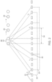
- Fig . 2 shows an embodiment according to the present invention of the MUT fingerprint ID system which uses a phased array of transducers to achieve a highly directional, focused acoustic beam.
- the acoustic beam is focused to a desired depth.
- an array with more channels and therefore larger aperture will focus the acoustic beam to a smaller diameter.
- an array with too many channels will make the electronics more complex and expensive.
- a phased array of transducers is used to achieve a highly directional, focused acoustic beam.
- this beam-forming approach while a group of transducers is utilized, not all of the transducers in the array are driven. Instead, smaller groups are driven, by example about 6 to 16 MUTs in a group, such as 10 to 15.
- a narrow focal diameter is achieved by increasing the aperture of the group by driving every other MUT (thereby doubling the aperture) or every third MUT (thereby tripling the aperture).
- an array of 6 MUTs operating at 40 MHz has a focal diameter below 50 ⁇ m when the transducer pitch is 150 ⁇ m, corresponding to an aperture of 750 microns.
- the MUT array can be fabricated with a 50 micron pitch, and a 150 micron pitch between the 6 MUTs in the group is created by driving every 3 rd MUT (MUT #: 1, 4, 7, 10, 13, 16).
- the array could have 75-micron pitch, in which case the group would be formed by driving every other PMUT (MUT #: 1, 3, 5, 7, 9, 11).
- the novel electronic scanning embodiment of MUT fingerprint ID system is provided where the beam is scanned by incrementally switching from one group of pixels to the next.
- the pitch between each MUT in the array is equal to the step-size of the scanning motion.
- a 50 ⁇ m pitch allows the beam to be scanned with a 50 ⁇ m step-size. Meanwhile, as described above, the pitch inside each MUT group can be enlarged to obtain a narrow acoustic beam. Finally, both a narrow acoustic beam and a small scanning step can be obtained, which subsequently contribute to a high sensing resolution and accuracy.
- the beam can be scanned over the full length of the MUT array of the MUT fingerprint ID system, which is about 5-20mm for a typical fingerprint sensor application.
- the beam is scanned in two axes using a two-dimensional array.
- the finger can be swiped across the array as is done in many capacitive fingerprint sensors. In the latter case, a smaller number of pixels is needed in the y-axis swiping direction.
- the phase of the signal applied to the y-axis pixels is controlled electronically to focus the beam in the y-axis, or the focusing can be achieved using a cylindrical acoustic focusing lens.
- a novel means of controlling the phase in the y-axis is to use row-column addressing in which the bottom electrode of the pixels is patterned and connected on each row. As a result, the phase delay of the signal is able to be applied to each channel, and a small focus area is obtained in both x and y axis.
- this additional strategy to separate these images is based on the time of flight of the echoes, and determining which echo comes first. Referring back to Fig. 1 , with a short time delay, an echo is discernible under epidermis valley 8. The echoes that come from the dermis layer 24 are received later. Because they have to propagate further into the tissue, by using time gating, the image to be received is selected.
- Data is collect for both the epidermis layer 23 and the dermis layer 24 of the same finger. This is possible because the dermis image collected is deeper, with a resulting longer time delay. By contrast, the epidermis image collected is more shallow, as it is on the surface of the skin, with a resulting shorter time delay. The image is collected with the short time delay recording, but both can be collected essentially simultaneously.
- Fig. 2 shows the beam forming design embodiment according to the present invention of the MUT fingerprint ID system.
- This beam forming design was inspired by the analogous medical imaging area.
- the configuration has a fairly large array of MUTs 24.
- the MUTs are arranged into groups; two groups 26 and 28 are illustrated here by way of example.
- the MUT pitch 30 is the distance between the adjacent MUTs 24 and is the same as the scanning step size 32 of the focused acoustic beam 25.
- the focused beam undergoes incremental motion with step size 32 equal to the MUT pitch 30.
- the intragroup pitch 34 is the pitch between the MUTs within the same group. By way of example, in Fig. 2 the intragroup pitch 34 is equal to four times the MUT pitch 30.
- MUT pitch 30 determines scanning step size 32.
- the MUT pitch 30 can be from about 10 ⁇ m to 130 ⁇ m specifically from about 30 ⁇ m to 60 ⁇ m, and more specifically from about 48 ⁇ m to 52 ⁇ m. If the step size 32 is 50 ⁇ m, this corresponds to 500dpi resolution for fingerprint identification at the criminal justice requirement level. However, achieving 250 dpi resolution requires only 100 ⁇ m step size. The latter level of fidelity is very acceptable for most consumer applications.
- MUT pitch 30 is the spacing between adjacent MUTs 24 in the array, and the spacing between MUTs within the same group is the intragroup pitch 34.
- Intragroup pitch 34 and the frequency of the transducer determine the focus diameter. If the operating frequency is decreased, a larger intragroup pitch 34 is required to keep the same focus diameter.
- the focus diameter determines the lateral resolution of the image, which is typically useful at about 50 ⁇ m.
- a particular group pitch is required to achieve a 50 ⁇ m spot size. By example, there can be 11 elements in the group and a 100 ⁇ m pitch between the elements in the group. Therefore, intragroup pitch 34 would be 100 ⁇ m.
- MUT fingerprint ID system embodiments can be scaled down when appropriate to the applications.
- the frequency was decreased from 40MHz to 20MHz, the intragroup pitch 34 would be doubled from 100 ⁇ m to 200 ⁇ m to maintain the same focused beam diameter. This would be the case when keeping the same number of elements in the group, that is 11.
- the focus spot is generated by varying the delay by applying a pulse signal to the transducers.
- a varying time delay is provided to the elements in the array such that the beam will be focused to a point at the finger-chip interface.
- This system provides enough depth of focus that that focus spot 25 still remains small at the first interface of the epidermis and at the deeper interface with the dermis. Once focus spot 25 is focused, it will be remain focused during the scanning process.
- the inventors' research has provided plots that show the depth of focus for a nominal design to be about 1.5mm, this information is included as Fig. 12 .
- These elements are driven as a phased array, and the beam is formed by appropriately controlling the time delays. All the transducers 24 in the group receive the signal. The 11 elements in a group act together to produce the sound, and those 11 elements detect the echo. This is beam forming and requires the array to work like a phased array.
- the output beam can be steered over a range of angles by continuously varying the phase of the drive signals applied to the transducers in a group.
- Another strategy is to maintain the focused spot 25 at a point centered above the group, as shown in Fig. 2 , and do the scanning of the spot by switching from one group to the next group.
- the transducers can be used as the system moves from group 1 to group 2 to group 3, and then back again.
- the incremental motion of the spot over the array continues by switching from group to group, allowing advancement of the beam (and the point where the image is being taken) by the scanning steps 25, 36 and 38, etc.
- Fig. 3 shows an embodiment of the MUT fingerprint ID system whose core engineering design is a non-beamforming system employing acoustics.
- piezoelectric micromachined ultrasonic transducers are utilized.
- PMUTs as with other MUTs, have the advantages of small size, easy fabrication, and easy integration with electronics.
- the PMUT embodiment of the MUT fingerprint ID system achieves a fast response time. Because this MUT fingerprint ID system design eliminates the need for mechanical scanning, it can function in an electronically-scanned live scan mode.
- the main feature of the PMUT embodiment of the MUT fingerprint ID system is the use of acoustic wave guides in lieu of, or in some cases augmented by, electronic phased-array beam focusing approaches.
- an array of PMUTs generates highly directional acoustic pulses, which transmit and reflect at the interface of two materials with different acoustic impedance.
- a coupling material with acoustic impedance similar to that of human tissue is filled between the ultrasonic transducers and the top surface of the sensor where the user's finger makes contact.
- the fingerprint consists of a pattern of ridges and valleys which have different acoustic impedance, resulting in measurable differences in the intensity of the reflected ultrasound.
- the same pattern is present on both the dermis and epidermis.
- the epidermal reflections arrive earlier than the deeper dermal reflections and timegating can be used to select whether the sensor records the dermal or epidermal fingerprint.
- the PMUT embodiment according to the present invention of the MUT fingerprint ID system avoids or mitigates errors created by finger contamination and dry, wet, dirty, or oily skin, which are the major sources of error in existing optical and capacitive fingerprint sensors.
- the pitch of the PMUT array will typically be smaller than 50.8 ⁇ m to achieve a final 500DPI image resolution. This resolution is the rule established by the FBI for an authenticating fingerprint sensor for the purposes of criminal investigations.
- a large PMUT bandwidth (>10MHz) can be provided.
- the height h of fingerprint pattern is around 75-150 ⁇ m.
- the PMUT array produces sufficient acoustic output at a low drive voltage, ideally less than 10V.
- the drive voltage can range from about 1V to 32V, specifically from about 2V to 15V and more specifically from about 3V to 8V.
- the acoustic beamwidth will typically be about ⁇ 100 ⁇ m.
- the focused acoustic beam size defines the accuracy of the fingerprint detection. Considering the fingerprint pattern's dimensions (ridge width about 100-300 ⁇ m, period ⁇ 500 ⁇ m), a focus size smaller than about 100 ⁇ m is employed to recognize the difference between ridges and valleys.
- waveguides 40 are provided to confine an individual PMUTs acoustic output such that a pulse-echo measurement from each PMUT can be conducted individually.
- the waveguides 40 function to confine the ultrasonic wave such that it can only propagate inside the waveguides 40. This makes the beam width very small, rather than omnidirectional.
- Each PMUT transducer 48 acts like an individual pixel of a camera, and takes an isolated image of the tissue contacting the top of its individual waveguide. Each time a transmitting pulse 44 signal is sent from one or several PMUT transducers 48, each PMUT transducer 48 receives back through coupling material 46 an echo 42 that is predominantly its own.
- coupling material 46 which has the same or similar acoustic impedance as human body tissue.
- water or other fluids could be used in this function.
- solids or gels are more suitable in most instances.
- PDMS Polydimethylsiloxane
- PDMS belongs to a group of polymeric organosilicon compounds that are commonly referred to as silicones.
- PDMS is the most widely used silicon-based organic polymer, and is particularly known for its unusual rheological (or flow) properties.
- PDMS is optically clear, and, in general, inert, non-toxic, and non-flammable. It is also called dimethicone and is one of several types of silicone oil (polymerized siloxane). Its current applications include contact lenses and medical devices as well as elastomers.
- both transmitting pulse 44 and echo pulse 42 will remain within the waveguide 40 and not propagate, or have very attenuated propagation, to neighboring ultrasonic transducers 48. As a result, each transducer 48 will receive essentially only its own echo pulse 42.
- the echo time delay 50 as determined by comparing the relative echo pulse 42 times from some or all of the transducers 48 is then used to provide a full, three dimensional picture of the fingerprint.
- the width of the fingerprint valley is about 100 ⁇ m to 300 ⁇ m.
- Valley range 47 is typically about 100-300 ⁇ m, representing the pitch of the ridge 49.
- a fingerprint ridge pitch is about 500 ⁇ m.
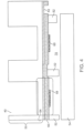
- Fig. 4 shows the basic structure of the PMUT array in the PMUT embodiment of the MUT fingerprint ID system.
- Each PMUT can transmit and receive acoustic waves. When a voltage is applied across the bottom and top electrodes, the transducer membrane vibrates, generating an acoustic wave in the surrounding medium. Conversely, an arriving acoustic wave creates motion in the PMUT, producing an electrical signal.
- PMUTs with center frequency of about >30MHz and pitch of about ⁇ 50 ⁇ m are useful ranges for some applications.
- a small driving voltage is desirable for the proposed fingerprint sensor to be used for portable devices.
- the required drive amplitude is approximated as follows: over the short ( ⁇ 100 ⁇ m) acoustic path length, absorption and scattering losses are negligible ( ⁇ 0.5dB) and the transmission loss is dominated by the reflection ratio, R, of the selected interface.
- the epidermis-dermis interface produces a smaller acoustic echo than the epidermis-air interface because the acoustic impedance difference between the dermis and epidermis layers is smaller.
- the reflection ratio R will be 0.015.
- the expected SNR is approximately 15dB assuming 7 ⁇ V RMS input-referred noise over a 50 MHz pre-amplifier bandwidth. This estimate is conservative: the desired imaging frame rate ( ⁇ 100 fps) means that the actual measurement bandwidth is orders of magnitude smaller than the bandwidth of the first amplification stage.
- phased-array techniques using multiple transducers driven in parallel could enable further increases in SNR.
- Fig. 4 shows one possible structure for the device depicted in Fig. 3 .
- wafer bonding 52 serves both as a connection and an anchor for the transducer.
- the wafer bonding 52 provided on CMOS wafer 54.
- the circuitry for the system is provided within the CMOS wafer 54.
- the PMUT is located in MEMS wafer 56, typically constructed of silicon.
- Transducer 58 can be either CMUT or PMUT.
- the waveguides may be produced by plasma etching tubes into the silicon MEMS wafer. Subsequently, post-fabrication processing is accomplished to fill in the waveguide tubes with PDMS or some other coupling material.
- the wafer bonding 52 anchors, and also serve as an electrical connection, between CMOS wafers 54 and MEMS wafers 56.
- CMOS wafers 54 For each MUT there will be a top electrode 60 typically constructed of metal.
- top electrode 60 and bottom electrode 62 are separated by an air-filled or vacuum-filled gap.
- Fig. 4 illustrates a PMUT having piezoelectric layer 66 between top electrode 60 and bottom electrode 62, with passive layer 64 located beneath piezoelectric layer 66.
- the PMUT's membrane structure is driven into vibration by applying an ac voltage across top electrode 60 and bottom electrode 66, creating an ultrasound wave that propagates into waveguide 40.
- Fig. 5 is a flow diagram of a typical fabrication process for the MUT fingerprint ID system, shown in Steps 1-5.
- the orientation shown in Fig. 5 is flipped from that of Fig. 4 , with which it shares many of the same features. This is because this is the orientation during manufacture rather than use.
- Step 1 of the fabrication process shows cavity SOI 72 as the base structure, including cavity 70.
- This style of wafer can be obtained premade from the foundry. In this case, it is termed a cavity SOI.
- Step 2 of the fabrication process includes deposition on the surface of device silicone layer 76 of bottom layer 62, typically constructed of (BE) Pt/Ti, and piezoelectric layer 66.
- Step 3 of the fabrication process includes via etching 78 of piezoelectric layer 66, typically using wet etching, to open bottom electrode 62.
- Step 4 of the fabrication process includes oxide deposition and patterning of capacitance reducing layer 80 at the edges of piezoelectric layer 66. This step is only one more layer, the top electrode, which is made of patterned materials.
- Step 5 of the fabrication process includes aluminum film deposition of metal layer 82, forming top electrode 60 and bottom electrode 62. It is important to open the layer at this point so that this metal layer connects to the bottom electrode, becoming part of bottom electrode 62.
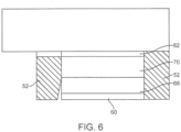
- Fig. 6 provides a generalized depiction of a system architecture that is particularly useful in employing CMUT transducers for the MUT fingerprint ID system. However, this structure can also employ PMUT transducers in some circumstances.
- the construction of the device in Fig. 6 in contrast to the embodiments shown in Fig. 4 , has no cavity.
- the architecture of the top of both of these device, however, is of a similar construction.
- the design still includes anchors 52, top electrode 60 and bottom electrode 62. However, a vacuum or air-filled gap 70 separates top electrode 60 and bottom electrode 62. Shown in the figure is an optional electrical insulation layer 68 covering top electrode 60. If an ac voltage is applied between the top and bottom electrode, again this insulation layer 68 along with the top electrode 60 will start vibrating. Just as in Fig. 4 , it will be the active layer vibrating. The insulation layer 68 along with the top electrode 60 will also emit an ultrasonic wave. As a result, these embodiments appear almost the same, however they differ in the construction of the MUT. Thus these embodiments achieve the same function but with a different approach.
- Fig. 7 shows an example electrical control and system of the MUT fingerprint ID system with different phase delays.
- the PMUT array 71 is patterned such that all the PMUTs in the same column share the same top electrodes (blue lines), while every PMUT's bottom electrode connect to local pre-amplifier or buffer circuitry 72. This can be done by, for example, pin-out, wafer bonding between circuit wafer and MEMS wafer, or monolithic process that enables circuitry and MEMS on a same die.
- the high voltage driver 73 send out a sequence of pulses, which could be delay controlled. Meanwhile, the switches 74 inside each cell in the array are closed via circuitry. Consequently the PMUT 75 is excited and send out a pulse with delay determined by the phase delay of the applied signal on top electrodes.
- the method 1 no beam-forming is needed, and hence each time only 1 of the columns, for example, column j is excited with the high-voltage driver. Hence all the PMUT on that column will be excited.
- the signal on PMUT would be amplified and buffered by buffer 76 and directed into data processing unit 77 to provide a fingerprint image.
- the data processing unit might contain necessary data converter, variable gain amplifier, digital beamformer, and other hardware to produce fingerprint image.
- Fig. 2 For beamforming method, different phase delays are applied to different columns to gives X-direction beam-forming as shown in Fig. 2 . To perform incremental scanning, the delay applied is shifted between high-voltage driver. The Y-direction beam-forming is done by data processing unit with the data comes from different rows. The receiving scheme and control is similar to method 1.
- the MUT fingerprint ID system is ideally suited for incorporation into existing consumer product designs, and, in later stage adoption, to enable entirely new products with unique functionality.
- the unprecedented small size, robust solid-state construction, and orders of magnitude lower cost per unit than current fingerprint ID systems opens a new era in personal identification capabilities, with transformational impact on personal electronic devices, many other consumer goods, and entry enablement devices.
- the MUT fingerprint ID system can enable existing personal electronic surfaces while still maintaining a standardized appearance.
- the identification surface will be paired with other functional surfaces of the device, such as camera lenses, speakers or microphones, to simplify electrical connection to the device circuitry.
- Internet enabled objects can be provided with authenticated fingerprints remotely, while others are programmed at the device.
- the MUT fingerprint ID system represents a transformational advancement in e-authentication, and is the successor to computer numeric and alphabetic passcodes. MUT fingerprint ID system will displace computer file user names, passwords, passcodes, and paraphrases, among others. Besides providing a much higher level of security, the MUT fingerprint ID system represents a substantially decreased burden on computer and internet users.
- the MUT fingerprint ID system provides an unprecedented level of personal authentication for on-line and other computer file access. Additionally, consumers will enjoy freedom from the current burdensome system of diverse password requirements for the multitude of systems to which they need access. Because of the fallible nature of password security, some systems even require new passwords and complex paraphrases be generated on a regular basis. As a result, many passwords are actually written and placed on the physical computer, defeating the intent of password secrecy.
- the biometric quality of the MUT fingerprint ID system provides authentication much superior to computer pass codes. Unlike codes which can be hacked or taken by trick, such as phishing, the complex, elegant authentication enabled by the MUT fingerprint ID system is robustly secure. In contrast to previous fingerprint identification systems, the MUT fingerprint ID system has the capability of analyzing depth and pitch of fingerprint ridges in a clear topographical style map. Also, the ultrasound characteristics of normal dermis and epidermal layers are very difficult to reproduce in a forgery attempt. Thus, it would be highly difficult, if not impossible, to produce an effective fingerprint forgery for the MUT Fingerprint ID System.
- the MUT Fingerprint ID System will replace pin codes and pass codes in coordination with physical objects, such as bank and credit cards. As broader adoption proceeds, the MUT Fingerprint ID System will eliminate the need for individuals to carry wallets or keys of any type.
- the MUT fingerprint ID system provides, for the first time, the capability of truly keyless authorized entry.
- entry to one's home and office, as well as entry and operation of one's car will require no physical "key", as a finger touch will open this areas to the appropriate persons.
- This unique capability of the MUT fingerprint ID system is particularly advantageous in the case of a forgotten, misplaced or stolen wallet or keys.
- the MUT fingerprint ID system eliminates the need of either traditional metal or electronic keys.
- the risk of loss or theft providing unauthorized entry inherent in currently available systems is dramatically reduced or eliminated.
- either gloves providing decloaking of a fingertip, or thin, ultrasound transparency of a glove fingertip can be employed.
- an authenticated individual touches an enabled key pad.
- the MUT fingerprint ID system will replace current electronic key pads, initially by retrofitting, and most secured building entry will be provided in this manner.
- the MUT fingerprint ID system detection surface can be either embedded into the surface of a standard door handle, or covered with a thin layer of decorative metal similar to that of the body of the handle.
- the detection surface of the MUT fingerprint ID system is so robust to abrasion and weather challenges, an overlay of a thin metal veneer or paint would be provided only for the sake of appearance or preferred texture.
- the authenticated individual may simply touch the door surface containing a MUT fingerprint ID system key pad to gain entry though electronic door opening activation. Authorization and entry are provided in a single movement, and do not require either a traditional metal key or electronic key.
- the system automatically authenticates the individual when their hand grasps the entry handle, and by the time the handle is turned, the door is released and is opened. Entry is thus permitted in a single movement. For isolated or late night entry to a building, the reduction of time required for entry minimizes risk of criminal activity.
- interior doors can be similarly enabled to allow entry.
- entry levels to different rooms within the building can be appropriately assigned.
- Tradespeople by example, will have entry authorization to power rooms, cleaning people to utility rooms, and executives to specific offices and file rooms. Elevator access to specific floors can be similarly limited to authorized individuals, when they touch the appropriate elevator button for the correct floor access.
- Remote authentication can be provided as required.
- the MUT fingerprint ID system provides a previously unavailable level of access authentication for objects by selected individuals.
- entry to trusted individuals is provided remotely, with the option to designate discreet, specific, limited periods of time as enabled by the MUT fingerprint ID system.
- objects to be accessed need not be internet enabled. In this case, physical contact is necessary to provide the necessary direction to the entry feature. This will be the main application in the early stages of the MUT fingerprint ID system adoption
- internet enabled objects provide a much broader range of authorization capabilities through the MUT fingerprint ID system.
- Tesla cars are internet enabled objects. Going forwards, internet enabled capability will be available in future models of more standard consumer cars.
- an access authorizer electronically receives e-fingerprints from trusted individual either directly or via internet transmission.
- the authorizer can than accept the trusted individual's fingerprint identification to receive access to an internet enabled object.
- the authorized fingerprint is transmitted to the internet enabled object remotely.
- the trusted individual is thus provided access at the appropriate level to the internet enabled object. Access can be both location and time limited.
- a parent can provide access to the family car to a teenage offspring for a specific purpose.
- the authorization may be to allow chores to be completed during a specified period.
- a layered access can be provided, that is authentication to enter the car and authentication to start the ignition and drive the car.
- the parent enabled access can be programed to lapse. If needed, the offspring can e-request a time extension of the parent.
- Non-drivers or those who should not drive could be provided access to the trunk to retrieve personal items, without making the main cab available to them.
- the MUT fingerprint ID system can allow a property owner to provide specific tradespeople a time limited, person specific entry capability in order to complete repair or other tasks during an anticipated period.
- the preauthorized building entry time can be extended remotely if needed.
- a broader period for initial entry, with a set period for task completion and later lapse of entry capability, can be provided. If needed, access can be extended remotely.
- a delivery person could be provided temporary access to the entry hall of a house to deposit a parcel in a safe manner.
- gradations of fingerprint authentication allow greater flexibility of the system to the purpose. Partial fingerprint recognition, at a lower level than required for criminal law identification, can be provided appropriately for many uses of the MUT fingerprint ID system.
- MUT fingerprint ID system In child safety applications, doors to cleaning supplies, medications, and liquor/cigarette cabinets can be MUT fingerprint ID system enabled. In that way, young children are protected from access to dangerous substances, and their safety level improved. Through use of the MUT fingerprint ID system, underage family members will be denied access to family cigarettes and alcohol supplies.
- the MUT fingerprint ID system can be included in the design of digital gun safes, such as First Alert 6742DF, Fire Resistant Executive Gun Safe, Homak Electronic Lock Pistol Box, and Elite Jr. Executive Fire Resistant Gun Safe, to provide appropriately limited access to firearms. As many firearm deaths are due to children accessing these weapons, the MUT fingerprint ID system will contribute to a lowering of these deaths. Additionally, the MUT fingerprint ID system components will provide greater safeguard against theft, with concomitant decrease of unregulated criminal use of unregistered firearms.
- the safety aspect of the MUT fingerprint ID system to limit firearm accidents will be extended.
- the X system can be included to that end in digital trigger locks such as the catmedwid/10000LOCK by Rrarms, among others.
- additional internet connectivity is provided to guns, such as the Tracking PointXactSystem Precision Guided Firearm, there will be more opportunities to limit unauthorized use of guns.
- the MUT fingerprint ID system can be used as a fail-safe guard by detecting the identity of the user from a fingerprint on the trigger, locking down the gun from use.
- each gun can be provided a fingerprint file to identify the user of the gun during criminal activity, much as a "black box" is used to gain information after an airplane crash.
- the MUT fingerprint ID system can be used to alert the proper authorities and potential victims when an unauthorized person is entering a building. For example, in domestic violence situations, an abusive spouse under a court stay-away order can be identified entering a building from their touch on the door surface. An e-alert would then be transmitted to the potential victim and building security in order to notify them to the possible impending threat. The intruder's position can be tracked though the touch of interior doors. Similarly, in day care facilities, non-custodial family members can be identified at the door, with an e-alert to the possible threat of a child abduction signaled to care providers.
- MUT fingerprint ID system sensing surface There are multiple surfaces on personal electronic devices on which the MUT fingerprint ID system sensing surface can be incorporated.
- the cases of personal electronic devices are excellent locations for the MUT fingerprint ID system sensing surface.
- These otherwise underutilized external areas of personal electronic devices provide the surface availability key to installation of the MUT fingerprint ID system.
- the MUT fingerprint ID system touch pad surface is highly robust to abrasion, fluids, dirt, scratches, and can function effectively even through dirt film and other contaminates. Abrasion and scratches from normal use will have little or no effect on functionality. The structural integrity of the surface, and its tensile strength, will avoid compromise of the overall integrity of the device casing in which it is located.
- this surface may be slightly inwardly recessed from the casing's overall surface.
- this slight indentation will provide a cue to the user as to the location of the touch pad.
- the MUT fingerprint ID system verification will be accomplished simply by a user picking up the device.
- the sensing surfaces are usefully located where the device would naturally be grasped for use. In some cases, this will be the surface the user would grasp to either open or hold the device.
- the MUT fingerprint ID system can be installed on the surface, and the connectivity to the control chip accomplished through the electrically conductive case material.
- the connectivity to the control chip accomplished through the electrically conductive case material.
- hard plastic or other non-conductive case materials are employed in personal electronic device cases, a connection to the motherboard or internet enabling circuitry will be required, but can be easily accomplished with co-located surface device features.
- Personal electronics represent a wide diversity of products. There are also crossovers between product types, such as tablets with cellphone capability, cell phones with large screens which serve as small tablets, Blackberry style capability in both cell phone and tablet formats, etc. Virtually all these products, both when combined in a single device, or when provided separately, will enjoy substantial increase in value and versatility when MUT fingerprint ID system is incorporated into their design.
- the MUT fingerprint ID system can allow entry into multiple software capabilities and files without the current inconvenience of requiring the input and recalling multiple passwords, each with their own unique requirements for form and complexity. Instead, these systems would enjoy a much higher level of authentication without impeding legitimate user access to the systems. Currently, software viruses often de-encrypt the usual cumbersome access codes. Thus, both security and ease of use are enabled by the MUT fingerprint ID system.
- the MUT fingerprint ID system will be usefully incorporated into standard cell phones.
- the MUT fingerprint ID system will also be an important feature when incorporated into a "smart phone”. Because of MUT fingerprint ID system's small size, very low cost, and robust solid state construction, it is particularly advantageous for use in smart phones.
- the cost of the MUT fingerprint ID system feature will be variable depending on the application and unit numbers. In some cases, where it is implemented with other device features, its cost will be negligible. In some cases, the cost per unit will be about $0.03 to $2 current US, specifically about $0.05 to $1 current US, and more specifically about $0.10 to $0.50 current US.
- Some examples of currently available, broadly used smart phones which could be improved by incorporating the MUT fingerprint ID system are BlackBerry Q10, BlackBerry Z10Sony Xperia Z, Samsung Galaxy Nexus, Samsung Galaxy S3, Samsung Galaxy Note 2, Samsung Galaxy S4, HTC First, HTC Windows Phone 8X, HTC Evo 4G LTE, HTC One X, HTC One X+, HTC Droid DNA; HTC OneApple iPhone 4S, iPhone 5, LG Optimus G, Nexus 4, Nokia Lumia 920, Motorola Droid Razr Maxx HD, among others.
- Other smart phones which can be modified to include MUT fingerprint ID system are Acer Allegro, Acer beTouch E110, Acer beTouch E130, Acer beTouch E140, Acer DX900, Acer neoTouch,Acer X960, Adaptxt, Android Dev Phone, Baidu Yi, BenQ P30, BlackBerry Porsche Design P'9981, BlackBerry Torch, BlackBerry Torch 9800, BlackBerry Charm, BlackBerry Electron, BlackBerry OS, BlackBerry Pearl, BlackBerry Q10, BlackBerry Q5, BlackBerry Quark, BlackBerry Storm, BlackBerry Storm 2, BlackBerry Style, BlackBerry Tour, BlackBerry Z10, Carrier IQ, Casio G'zOne Commando, Celio Technology Corporation, Comparison of Android devices, Curzon Memories App, CyanogenMod, Dell Streak, Dell Venue Pro, Digital Ocean, Droid Charge, Droid Incredible, Droid Pro, Droid X, FairPhone, Neo 1973, Neo FreeRunner, Find My Phone, Fujitsu Toshiba IS12T,Galaxy Nexus, Garmin Nüvifone, GeeksPh
- the MUT fingerprint ID system has particular advantages as a new feature for electronic tablets.
- the MUT fingerprint ID system allows a user easy access without having to resort to typing in passcodes.
- Passcodes have limitations, such as when a user is on public transportation with considerable motion interfering with typing accuracy, or where the device needs to be quickly accessed through reentry multiple times.
- the MUT fingerprint ID system enabled fingerprint verification of owner identity is an important factor in disincentivizing theft.
- Examples of electronic tables which can usefully include MUT fingerprint ID system are: iPadApple A4, Apple A5, Apple A5X, Apple A6X and mini Apple A5, HP Slate 7 8G Tablet Samsung GALAXY NOTE 8.0, Samsung GALAXY NOTE 10.1 among many others.
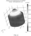
- the 1st order resonant mode of PMUT was obtained by some of the present inventors by finite element method (FEM) using commercial software (COMSOL).
- Fig. 8 shows the finite element analysis simulation of the vibration mode shape of a PMUT.
- the resonant frequency of PMUT (with layer stack 0.5 ⁇ m AIN/ 2 ⁇ m Si and 25 ⁇ m diameter) in the air was about 64.8 MHz.
- the resonant frequency is proportional to membrane thickness and inversely proportional to membrane diameter squared.
- Fig. 9 shows the first resonant frequency of PMUTs as a function of diameter (layer stack 0.5 ⁇ m AlN/2 ⁇ m Si). Higher working frequency generates a smaller acoustic wavelength, resulting in a higher resolution fingerprint image.
- Fig. 10 shows the simulated acoustic beam pattern of PMUT arrays having different pitches.
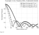
- Fig. 11 shows the experimentally measured pressure pattern from a 15-column PMUT array.
- the pressure was measured by scanning a 40 micron hydrophone across the array at a distance of approximately 1.5 mm from the array. Measurements were made driving every PMUT (70 micron pitch) and every other PMUT (140 micron pitch).
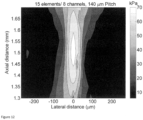
- Fig. 12 shows the experimentally measured pressure pattern from a 15-column PMUT array.
- the pressure was measured by scanning a 40 micron hydrophone across the array in both the x and z (axial) directions.
- the PMUTs have a 140 micron pitch and beamforming is used wherein the phase of each column is controlled to produce a focused acoustic beam.
Applications Claiming Priority (2)
| Application Number | Priority Date | Filing Date | Title |
|---|---|---|---|
| US201361846925P | 2013-07-16 | 2013-07-16 | |
| PCT/US2014/046557 WO2015009635A1 (en) | 2013-07-16 | 2014-07-14 | Mut fingerprint id system |
Publications (3)
| Publication Number | Publication Date |
|---|---|
| EP3022683A1 EP3022683A1 (en) | 2016-05-25 |
| EP3022683A4 EP3022683A4 (en) | 2017-03-22 |
| EP3022683B1 true EP3022683B1 (en) | 2024-01-17 |
Family
ID=52346663
Family Applications (1)
| Application Number | Title | Priority Date | Filing Date |
|---|---|---|---|
| EP14825944.3A Active EP3022683B1 (en) | 2013-07-16 | 2014-07-14 | Mut fingerprint identification system |
Country Status (6)
| Country | Link |
|---|---|
| US (2) | US10430631B2 (ja) |
| EP (1) | EP3022683B1 (ja) |
| JP (1) | JP6616296B2 (ja) |
| KR (1) | KR102305274B1 (ja) |
| CN (2) | CN111626111B (ja) |
| WO (1) | WO2015009635A1 (ja) |
Families Citing this family (112)
| Publication number | Priority date | Publication date | Assignee | Title |
|---|---|---|---|---|
| US10217045B2 (en) | 2012-07-16 | 2019-02-26 | Cornell University | Computation devices and artificial neurons based on nanoelectromechanical systems |
| US9114977B2 (en) | 2012-11-28 | 2015-08-25 | Invensense, Inc. | MEMS device and process for RF and low resistance applications |
| US9618405B2 (en) | 2014-08-06 | 2017-04-11 | Invensense, Inc. | Piezoelectric acoustic resonator based sensor |
| US10497747B2 (en) * | 2012-11-28 | 2019-12-03 | Invensense, Inc. | Integrated piezoelectric microelectromechanical ultrasound transducer (PMUT) on integrated circuit (IC) for fingerprint sensing |
| US10726231B2 (en) | 2012-11-28 | 2020-07-28 | Invensense, Inc. | Integrated piezoelectric microelectromechanical ultrasound transducer (PMUT) on integrated circuit (IC) for fingerprint sensing |
| US9511994B2 (en) | 2012-11-28 | 2016-12-06 | Invensense, Inc. | Aluminum nitride (AlN) devices with infrared absorption structural layer |
| CA2929723C (en) * | 2013-12-12 | 2020-09-15 | Qualcomm Incorporated | Micromechanical ultrasonic transducers and display |
| US9633269B2 (en) * | 2014-09-05 | 2017-04-25 | Qualcomm Incorporated | Image-based liveness detection for ultrasonic fingerprints |
| EP3757884A1 (en) * | 2014-09-08 | 2020-12-30 | InvenSense, Inc. | Integrated piezoelectric microelectromechanical ultrasound transducer (pmut) on integrated circuit (ic) for fingerprint sensing |
| US9952095B1 (en) | 2014-09-29 | 2018-04-24 | Apple Inc. | Methods and systems for modulation and demodulation of optical signals |
| US9747488B2 (en) * | 2014-09-30 | 2017-08-29 | Apple Inc. | Active sensing element for acoustic imaging systems |
| US9607203B1 (en) | 2014-09-30 | 2017-03-28 | Apple Inc. | Biometric sensing device with discrete ultrasonic transducers |
| US10133904B2 (en) * | 2014-09-30 | 2018-11-20 | Apple Inc. | Fully-addressable sensor array for acoustic imaging systems |
| US9984271B1 (en) | 2014-09-30 | 2018-05-29 | Apple Inc. | Ultrasonic fingerprint sensor in display bezel |
| US9824254B1 (en) | 2014-09-30 | 2017-11-21 | Apple Inc. | Biometric sensing device with discrete ultrasonic transducers |
| US9979955B1 (en) | 2014-09-30 | 2018-05-22 | Apple Inc. | Calibration methods for near-field acoustic imaging systems |
| US9904836B2 (en) | 2014-09-30 | 2018-02-27 | Apple Inc. | Reducing edge effects within segmented acoustic imaging systems |
| US10008659B2 (en) * | 2014-12-09 | 2018-06-26 | Lg Innotek Co., Ltd. | Fingerprint sensor |
| KR102402146B1 (ko) * | 2015-04-21 | 2022-05-26 | 삼성전자주식회사 | 지문 감지 방법 및 장치 |
| US10387704B2 (en) * | 2015-06-29 | 2019-08-20 | Qualcomm Incorporated | Method and apparatus for enabling the touchscreen display of a mobile device |
| US9830497B2 (en) * | 2015-07-05 | 2017-11-28 | Qualcomm Incorporated | Correction of diffraction effects in an ultrasonic sensor |
| US9928398B2 (en) | 2015-08-17 | 2018-03-27 | Invensense, Inc. | Always-on sensor device for human touch |
| US11048902B2 (en) | 2015-08-20 | 2021-06-29 | Appple Inc. | Acoustic imaging system architecture |
| US10004432B2 (en) * | 2015-09-01 | 2018-06-26 | Qualcomm Incorporated | Pixel receiver with capacitance cancellation for ultrasonic imaging apparatus |
| US10275638B1 (en) | 2015-09-29 | 2019-04-30 | Apple Inc. | Methods of biometric imaging of input surfaces |
| CN105380632B (zh) * | 2015-10-23 | 2018-11-30 | 江苏久祥汽车电器集团有限公司 | 具有高安全性能的生物识别机器人系统 |
| SE539636C2 (en) | 2016-03-14 | 2017-10-24 | Fingerprint Cards Ab | Capacitive fingerprint sensing device and method for capturing a fingerprint using the sensing device |
| CN105975044B (zh) * | 2016-04-25 | 2020-03-31 | Oppo广东移动通信有限公司 | 一种通过指纹检测自动控制触摸屏湿手模式的方法及装置 |
| US9898640B2 (en) * | 2016-05-02 | 2018-02-20 | Fingerprint Cards Ab | Capacitive fingerprint sensing device and method for capturing a fingerprint using the sensing device |
| US10325915B2 (en) | 2016-05-04 | 2019-06-18 | Invensense, Inc. | Two-dimensional array of CMOS control elements |
| US10656255B2 (en) * | 2016-05-04 | 2020-05-19 | Invensense, Inc. | Piezoelectric micromachined ultrasonic transducer (PMUT) |
| US10315222B2 (en) | 2016-05-04 | 2019-06-11 | Invensense, Inc. | Two-dimensional array of CMOS control elements |
| US10445547B2 (en) | 2016-05-04 | 2019-10-15 | Invensense, Inc. | Device mountable packaging of ultrasonic transducers |
| US10670716B2 (en) | 2016-05-04 | 2020-06-02 | Invensense, Inc. | Operating a two-dimensional array of ultrasonic transducers |
| US10366269B2 (en) | 2016-05-06 | 2019-07-30 | Qualcomm Incorporated | Biometric system with photoacoustic imaging |
| US10235551B2 (en) | 2016-05-06 | 2019-03-19 | Qualcomm Incorporated | Biometric system with photoacoustic imaging |
| US10706835B2 (en) | 2016-05-10 | 2020-07-07 | Invensense, Inc. | Transmit beamforming of a two-dimensional array of ultrasonic transducers |
| US10408797B2 (en) | 2016-05-10 | 2019-09-10 | Invensense, Inc. | Sensing device with a temperature sensor |
| US10562070B2 (en) | 2016-05-10 | 2020-02-18 | Invensense, Inc. | Receive operation of an ultrasonic sensor |
| US10632500B2 (en) | 2016-05-10 | 2020-04-28 | Invensense, Inc. | Ultrasonic transducer with a non-uniform membrane |
| US10539539B2 (en) | 2016-05-10 | 2020-01-21 | Invensense, Inc. | Operation of an ultrasonic sensor |
| US10452887B2 (en) * | 2016-05-10 | 2019-10-22 | Invensense, Inc. | Operating a fingerprint sensor comprised of ultrasonic transducers |
| US11673165B2 (en) | 2016-05-10 | 2023-06-13 | Invensense, Inc. | Ultrasonic transducer operable in a surface acoustic wave (SAW) mode |
| US10600403B2 (en) | 2016-05-10 | 2020-03-24 | Invensense, Inc. | Transmit operation of an ultrasonic sensor |
| US10441975B2 (en) | 2016-05-10 | 2019-10-15 | Invensense, Inc. | Supplemental sensor modes and systems for ultrasonic transducers |
| CN106166078B (zh) * | 2016-06-27 | 2020-04-10 | 业成科技(成都)有限公司 | 超声波感测装置及其感测方法 |
| TWI701581B (zh) * | 2016-07-22 | 2020-08-11 | 仟融科技股份有限公司 | 指紋觸控裝置及其驅動方法 |
| KR102019957B1 (ko) * | 2016-09-21 | 2019-11-04 | 크루셜텍 (주) | 생체 정보 센서 및 오브젝트 인증 방법 |
| US10410034B2 (en) | 2016-11-07 | 2019-09-10 | Qualcomm Incorporated | Ultrasonic biometric system with harmonic detection |
| WO2018112701A1 (zh) * | 2016-12-19 | 2018-06-28 | 深圳市汇顶科技股份有限公司 | 盖板、生物识别装置及终端 |
| FR3060810B1 (fr) * | 2016-12-21 | 2020-07-10 | Moduleus | Dispositif de stockage externe de donnees muni d'un capteur biometrique ultrasonore |
| CN106711320A (zh) * | 2017-01-09 | 2017-05-24 | 清华大学 | 一种超声波指纹采集器件及其制备方法 |
| CN108509829B (zh) * | 2017-02-28 | 2019-11-26 | 京东方科技集团股份有限公司 | 显示基板及其驱动方法、显示装置 |
| US9953205B1 (en) | 2017-04-28 | 2018-04-24 | The Board Of Trustees Of The Leland Stanford Junior University | Acoustic biometric touch scanner |
| US10489627B2 (en) | 2017-04-28 | 2019-11-26 | The Board Of Trustees Of The Leland Stanford Junior University | Acoustic biometric touch scanner |
| CN107194327B (zh) * | 2017-04-28 | 2019-02-15 | 维沃移动通信有限公司 | 一种指纹识别装置、方法及移动终端 |
| US10846501B2 (en) | 2017-04-28 | 2020-11-24 | The Board Of Trustees Of The Leland Stanford Junior University | Acoustic biometric touch scanner |
| US10891461B2 (en) | 2017-05-22 | 2021-01-12 | Invensense, Inc. | Live fingerprint detection utilizing an integrated ultrasound and infrared sensor |
| US11144158B2 (en) * | 2017-05-24 | 2021-10-12 | Apple Inc. | Differential acoustic touch and force sensing |
| CN107256391B (zh) * | 2017-05-31 | 2020-10-13 | 北京小米移动软件有限公司 | Lcd面板、lcm、指纹识别方法、装置及存储介质 |
| US10474862B2 (en) | 2017-06-01 | 2019-11-12 | Invensense, Inc. | Image generation in an electronic device using ultrasonic transducers |
| US10569302B2 (en) * | 2017-06-26 | 2020-02-25 | Qualcomm Incorporated | Biometric sensor with force detection and ultrasonic imaging capability |
| US10643052B2 (en) | 2017-06-28 | 2020-05-05 | Invensense, Inc. | Image generation in an electronic device using ultrasonic transducers |
| KR101911183B1 (ko) * | 2017-07-20 | 2018-12-19 | 이승진 | 임피던스를 이용한 페이크 지문 판별장치 및 방법 |
| US10461124B2 (en) * | 2017-08-07 | 2019-10-29 | Invensense, Inc. | Ultrasonic sensing device |
| US10691912B2 (en) * | 2017-08-09 | 2020-06-23 | The Board Of Trustees Of The Leland Stanford Junior University | Ultrasonic biometric sensing device integrated with optics |
| CN109472182B (zh) * | 2017-09-08 | 2020-09-22 | 茂丞科技(深圳)有限公司 | 晶圆级超声波芯片规模制造及封装方法 |
| CN107659204B (zh) * | 2017-09-28 | 2023-12-26 | 成都大超科技有限公司 | 超声波驱动电路和指纹识别传感器 |
| CN107832594A (zh) * | 2017-09-28 | 2018-03-23 | 芯海科技(深圳)股份有限公司 | 一种低成本的指纹童锁实现方法 |
| WO2019109010A1 (en) | 2017-12-01 | 2019-06-06 | Invensense, Inc. | Darkfield tracking |
| US10997388B2 (en) | 2017-12-01 | 2021-05-04 | Invensense, Inc. | Darkfield contamination detection |
| US10984209B2 (en) | 2017-12-01 | 2021-04-20 | Invensense, Inc. | Darkfield modeling |
| US10988376B2 (en) | 2017-12-13 | 2021-04-27 | Vanguard International Semiconductor Singapore Pte. Ltd. | Monolithic integration of piezoelectric micromachined ultrasonic transducers and CMOS and method for producing the same |
| WO2019125273A1 (en) * | 2017-12-21 | 2019-06-27 | Fingerprint Cards Ab | Display arrangement comprising ultrasonic biometric sensing system and method for manufacturing the display arrangement |
| KR102433315B1 (ko) * | 2017-12-27 | 2022-08-16 | 삼성전자주식회사 | 초음파 트랜스듀서가 임베디드된 유기 발광 다이오드 패널 및 이를 포함하는 표시 장치 |
| US11151355B2 (en) | 2018-01-24 | 2021-10-19 | Invensense, Inc. | Generation of an estimated fingerprint |
| US10802651B2 (en) | 2018-01-30 | 2020-10-13 | Apple Inc. | Ultrasonic touch detection through display |
| KR102608821B1 (ko) | 2018-02-08 | 2023-12-04 | 삼성메디슨 주식회사 | 무선 초음파 프로브 및 무선 초음파 프로브와 연결되는 초음파 영상 장치 |
| US11515465B2 (en) * | 2018-02-26 | 2022-11-29 | Invensense, Inc. | EMI reduction in piezoelectric micromachined ultrasound transducer array |
| US10755067B2 (en) * | 2018-03-22 | 2020-08-25 | Invensense, Inc. | Operating a fingerprint sensor comprised of ultrasonic transducers |
| CN108932775B (zh) * | 2018-07-10 | 2020-08-07 | 蒋钱 | 指纹锁身份识别系统 |
| CN109083510A (zh) * | 2018-10-16 | 2018-12-25 | 北京集创北方科技股份有限公司 | 一种指纹锁 |
| US11329098B2 (en) * | 2018-11-08 | 2022-05-10 | Vanguard International Semiconductor Singapore Pte. Ltd. | Piezoelectric micromachined ultrasonic transducers and methods for fabricating thereof |
| WO2020102965A1 (zh) * | 2018-11-20 | 2020-05-28 | 深圳市汇顶科技股份有限公司 | 超声换能器件及电子装置 |
| TW202034217A (zh) * | 2018-12-07 | 2020-09-16 | 美商蝴蝶網路公司 | 超音波指紋偵測和相關設備及方法 |
| US11354926B2 (en) | 2018-12-07 | 2022-06-07 | Bfly Operations, Inc. | Ultrasound fingerprint detection and related apparatus and methods |
| US10936843B2 (en) | 2018-12-28 | 2021-03-02 | Invensense, Inc. | Segmented image acquisition |
| US20220197987A1 (en) * | 2019-05-17 | 2022-06-23 | The Regents Of The University Of California | Biometric identification through intra-body communication |
| CN115917485A (zh) * | 2019-05-21 | 2023-04-04 | 京东方科技集团股份有限公司 | 用于产生和检测超声波感测信号的传感器电路、超声波感测显示设备 |
| CN110245629B (zh) * | 2019-06-19 | 2021-07-27 | 业成科技(成都)有限公司 | 电子装置及其制造方法 |
| US11188735B2 (en) | 2019-06-24 | 2021-11-30 | Invensense, Inc. | Fake finger detection using ridge features |
| CN112131905A (zh) * | 2019-06-24 | 2020-12-25 | Oppo广东移动通信有限公司 | 超声波指纹识别方法、装置、存储介质及电子设备 |
| WO2020264046A1 (en) | 2019-06-25 | 2020-12-30 | Invensense, Inc. | Fake finger detection based on transient features |
| CN110286738B (zh) * | 2019-06-29 | 2021-06-08 | Oppo广东移动通信有限公司 | 指纹采集方法及相关产品 |
| US11216632B2 (en) | 2019-07-17 | 2022-01-04 | Invensense, Inc. | Ultrasonic fingerprint sensor with a contact layer of non-uniform thickness |
| US11176345B2 (en) | 2019-07-17 | 2021-11-16 | Invensense, Inc. | Ultrasonic fingerprint sensor with a contact layer of non-uniform thickness |
| CN110472606B (zh) * | 2019-08-21 | 2022-05-20 | 京东方科技集团股份有限公司 | 一种超声波识别模组、其驱动方法及显示装置 |
| US11232549B2 (en) | 2019-08-23 | 2022-01-25 | Invensense, Inc. | Adapting a quality threshold for a fingerprint image |
| CN113168531B (zh) * | 2019-09-24 | 2022-07-15 | 指纹卡安娜卡敦知识产权有限公司 | 超声生物计量成像系统和用于控制超声生物计量成像系统的方法 |
| US11392789B2 (en) | 2019-10-21 | 2022-07-19 | Invensense, Inc. | Fingerprint authentication using a synthetic enrollment image |
| TWM606450U (zh) * | 2019-11-12 | 2021-01-11 | 神盾股份有限公司 | 超聲波指紋感測器 |
| EP3827906A1 (en) * | 2019-11-29 | 2021-06-02 | Imec VZW | A phased array ultrasound device for creating a pressure focus point |
| CN113597612B (zh) * | 2019-12-06 | 2022-08-09 | 京东方科技集团股份有限公司 | 超声指纹识别单元、指纹识别装置和指纹识别驱动方法 |
| CN115551650A (zh) | 2020-03-09 | 2022-12-30 | 应美盛公司 | 具有非均匀厚度的接触层的超声指纹传感器 |
| US11243300B2 (en) | 2020-03-10 | 2022-02-08 | Invensense, Inc. | Operating a fingerprint sensor comprised of ultrasonic transducers and a presence sensor |
| US11950512B2 (en) | 2020-03-23 | 2024-04-02 | Apple Inc. | Thin-film acoustic imaging system for imaging through an exterior surface of an electronic device housing |
| US11328165B2 (en) | 2020-04-24 | 2022-05-10 | Invensense, Inc. | Pressure-based activation of fingerprint spoof detection |
| US11719671B2 (en) * | 2020-10-26 | 2023-08-08 | UltraSense Systems, Inc. | Methods of distinguishing among touch events |
| DE102020214925A1 (de) | 2020-11-27 | 2022-06-02 | Robert Bosch Gesellschaft mit beschränkter Haftung | Verfahren zur Herstellung eines Polysilizium-SOI-Substrats mit einer Kavität |
| CN112871614B (zh) * | 2021-01-12 | 2022-03-15 | 武汉大学 | 高发射性能的mems超声换能器 |
| KR20220129334A (ko) * | 2021-03-16 | 2022-09-23 | 삼성전자주식회사 | 초음파를 이용하여 지문 이미지를 식별하는 전자 장치 및 이의 동작 방법 |
| CN115482605A (zh) * | 2021-05-26 | 2022-12-16 | 华为技术有限公司 | 一种指纹识别方法及电子设备 |
Family Cites Families (28)
| Publication number | Priority date | Publication date | Assignee | Title |
|---|---|---|---|---|
| US5224174A (en) * | 1990-11-07 | 1993-06-29 | Niagara Technology Incorporated | Surface feature mapping using high resolution c-scan ultrasonography |
| JP2557796B2 (ja) * | 1993-10-19 | 1996-11-27 | 株式会社エニックス | 圧電型面圧入力パネル |
| US5456256A (en) * | 1993-11-04 | 1995-10-10 | Ultra-Scan Corporation | High resolution ultrasonic imaging apparatus and method |
| US5647364A (en) * | 1995-02-15 | 1997-07-15 | Ultra-Scan Corporation | Ultrasonic biometric imaging and identity verification system |
| JP2000346610A (ja) * | 1999-03-31 | 2000-12-15 | Mitsubishi Electric Corp | 凹凸検出センサ、凹凸検出装置、指紋照合装置および個人判別装置 |
| AU2001245936A1 (en) * | 2000-03-23 | 2001-10-03 | Cross Match Technologies, Inc. | Piezoelectric identification device and applications thereof |
| US7067962B2 (en) * | 2000-03-23 | 2006-06-27 | Cross Match Technologies, Inc. | Multiplexer for a piezo ceramic identification device |
| US7141918B2 (en) * | 2000-03-23 | 2006-11-28 | Cross Match Technologies, Inc. | Method for obtaining biometric data for an individual in a secure transaction |
| KR20030005157A (ko) * | 2000-07-19 | 2003-01-17 | 김영완 | 무카드 보안 신용 거래 처리용 시스템 및 방법 |
| ATE406626T1 (de) * | 2002-01-17 | 2008-09-15 | Cross Match Technologies Inc | Fingerabdruck-workstation und verfahren |
| US7113070B2 (en) | 2003-03-21 | 2006-09-26 | Sheng Bill Deng | Door lock and operation mechanism |
| JP2005110934A (ja) * | 2003-10-07 | 2005-04-28 | Matsushita Electric Ind Co Ltd | 超音波診断装置 |
| KR100561851B1 (ko) * | 2003-11-18 | 2006-03-16 | 삼성전자주식회사 | 지문 인식 센서 및 그 제조 방법 |
| US8165355B2 (en) * | 2006-09-11 | 2012-04-24 | Validity Sensors, Inc. | Method and apparatus for fingerprint motion tracking using an in-line array for use in navigation applications |
| WO2006042144A2 (en) | 2004-10-07 | 2006-04-20 | Ultra-Scan Corporation | Ultrasonic fingerprint scanning utilizing a plane wave |
| CA2597831A1 (en) * | 2004-11-02 | 2006-05-11 | Cross Match Technologies, Inc. | Multiplexer for a piezo ceramic identification device |
| US20070230754A1 (en) * | 2006-03-30 | 2007-10-04 | Jain Anil K | Level 3 features for fingerprint matching |
| CA2653202A1 (en) * | 2006-05-25 | 2008-06-05 | Ultra-Scan Corporation | Biometrical object reader having an ultrasonic wave manipulation device |
| CA2684788A1 (en) | 2007-04-20 | 2009-02-05 | Ultra-Scan Corporation | Reliability improvement for piezoelectric imaging array device |
| US20100256498A1 (en) | 2007-11-16 | 2010-10-07 | Hiroki Tanaka | Ultrasonic imaging device |
| US8331633B2 (en) * | 2008-05-08 | 2012-12-11 | Sonavation, Inc. | Method and system for multi-mode mechanical resonator |
| TW200949638A (en) * | 2008-05-22 | 2009-12-01 | Novatek Microelectronics Corp | Touch detecting device capable of saving electricity |
| EP2310093A2 (en) | 2008-07-10 | 2011-04-20 | Cornell University | Ultrasound wave generating apparatus |
| CN102159334A (zh) * | 2008-09-16 | 2011-08-17 | 皇家飞利浦电子股份有限公司 | 电容性微机械加工的超声换能器 |
| US8508103B2 (en) * | 2009-03-23 | 2013-08-13 | Sonavation, Inc. | Piezoelectric identification device and applications thereof |
| JP2012204874A (ja) * | 2011-03-23 | 2012-10-22 | Olympus Corp | 超音波照射装置 |
| US9442095B2 (en) * | 2011-06-15 | 2016-09-13 | Northwestern University | Optical coherence photoacoustic microscopy |
| US8836472B2 (en) * | 2011-11-23 | 2014-09-16 | Blackberry Limited | Combining navigation and fingerprint sensing |
-
2014
- 2014-07-14 KR KR1020157037001A patent/KR102305274B1/ko active IP Right Grant
- 2014-07-14 CN CN202010312022.7A patent/CN111626111B/zh active Active
- 2014-07-14 WO PCT/US2014/046557 patent/WO2015009635A1/en active Application Filing
- 2014-07-14 US US14/896,150 patent/US10430631B2/en active Active
- 2014-07-14 EP EP14825944.3A patent/EP3022683B1/en active Active
- 2014-07-14 CN CN201480040556.1A patent/CN105378756B/zh active Active
- 2014-07-14 JP JP2016527017A patent/JP6616296B2/ja active Active
-
2019
- 2019-08-28 US US16/554,053 patent/US11238258B2/en active Active
Also Published As
| Publication number | Publication date |
|---|---|
| JP6616296B2 (ja) | 2019-12-04 |
| US20160117541A1 (en) | 2016-04-28 |
| CN105378756A (zh) | 2016-03-02 |
| CN111626111B (zh) | 2024-03-08 |
| EP3022683A1 (en) | 2016-05-25 |
| CN105378756B (zh) | 2020-05-08 |
| KR20160032045A (ko) | 2016-03-23 |
| WO2015009635A1 (en) | 2015-01-22 |
| JP2016533234A (ja) | 2016-10-27 |
| US11238258B2 (en) | 2022-02-01 |
| KR102305274B1 (ko) | 2021-09-24 |
| US20200167538A1 (en) | 2020-05-28 |
| US10430631B2 (en) | 2019-10-01 |
| EP3022683A4 (en) | 2017-03-22 |
| CN111626111A (zh) | 2020-09-04 |
Similar Documents
| Publication | Publication Date | Title |
|---|---|---|
| US11238258B2 (en) | MUT fingerprint ID system | |
| TWI831842B (zh) | 具有可撓性基板之超音波指紋感測器 | |
| KR102456391B1 (ko) | 광학계와 통합된 초음파 생체 인식 장치 | |
| KR102452268B1 (ko) | 하이브리드 용량성 및 초음파 감지 | |
| JP2022184843A (ja) | 音響生体識別タッチスキャナ | |
| USRE47158E1 (en) | Piezoelectric identification device and applications thereof | |
| US20030001459A1 (en) | Secure wireless sales transaction using print information to verify a purchaser's identity | |
| WO2019089432A1 (en) | System and method associated with user authentication based on an acoustic-based echo-signature | |
| EP3449419B1 (en) | Ultrasound fingerprint sensing and sensor fabrication | |
| KR20070101244A (ko) | 압전 세라믹 식별 장치용 멀티플렉서 | |
| US20190180078A1 (en) | Enhancing quality of a fingerprint image | |
| Peng et al. | Broadband piezoelectric transducers for under-display ultrasonic fingerprint sensing applications | |
| KR20170115225A (ko) | 지문인식모듈과, 이것이 적용된 전자기기, 그리고 이를 위한 음파제어부재의 제조방법 | |
| KR102161317B1 (ko) | 글래스 일체형 초음파 지문인식 센서 | |
| EP3803690B1 (en) | Acoustic biometric imaging system with acoustic impedance matched opaque masking layer, and manufacturing method | |
| US20220392249A1 (en) | Deep finger ultrasonic sensor | |
| KR102160716B1 (ko) | 다중 초음파 방식의 투명 패널 생체정보 인식 시스템 | |
| CN115398490A (zh) | 具有隐约指纹检测的指纹传感器 |
Legal Events
| Date | Code | Title | Description |
|---|---|---|---|
| PUAI | Public reference made under article 153(3) epc to a published international application that has entered the european phase |
Free format text: ORIGINAL CODE: 0009012 |
|
| STAA | Information on the status of an ep patent application or granted ep patent |
Free format text: STATUS: REQUEST FOR EXAMINATION WAS MADE |
|
| 17P | Request for examination filed |
Effective date: 20160204 |
|
| AK | Designated contracting states |
Kind code of ref document: A1 Designated state(s): AL AT BE BG CH CY CZ DE DK EE ES FI FR GB GR HR HU IE IS IT LI LT LU LV MC MK MT NL NO PL PT RO RS SE SI SK SM TR |
|
| AX | Request for extension of the european patent |
Extension state: BA ME |
|
| RIN1 | Information on inventor provided before grant (corrected) |
Inventor name: HORSLEY, DAVID Inventor name: LU, YIPENG Inventor name: BOSER, BERNHARD Inventor name: TANG, HAO-YEN |
|
| DAX | Request for extension of the european patent (deleted) | ||
| A4 | Supplementary search report drawn up and despatched |
Effective date: 20170217 |
|
| RIC1 | Information provided on ipc code assigned before grant |
Ipc: G06K 9/00 20060101AFI20170213BHEP |
|
| STAA | Information on the status of an ep patent application or granted ep patent |
Free format text: STATUS: EXAMINATION IS IN PROGRESS |
|
| 17Q | First examination report despatched |
Effective date: 20210226 |
|
| STAA | Information on the status of an ep patent application or granted ep patent |
Free format text: STATUS: EXAMINATION IS IN PROGRESS |
|
| REG | Reference to a national code |
Ref country code: DE Ref legal event code: R079 Ref document number: 602014089360 Country of ref document: DE Free format text: PREVIOUS MAIN CLASS: G06K0009000000 Ipc: G06V0040130000 Ref country code: DE Ref legal event code: R079 Free format text: PREVIOUS MAIN CLASS: G06K0009000000 Ipc: G06V0040130000 |
|
| GRAP | Despatch of communication of intention to grant a patent |
Free format text: ORIGINAL CODE: EPIDOSNIGR1 |
|
| STAA | Information on the status of an ep patent application or granted ep patent |
Free format text: STATUS: GRANT OF PATENT IS INTENDED |
|
| RIC1 | Information provided on ipc code assigned before grant |
Ipc: G06V 40/13 20220101AFI20230906BHEP |
|
| INTG | Intention to grant announced |
Effective date: 20230921 |
|
| GRAS | Grant fee paid |
Free format text: ORIGINAL CODE: EPIDOSNIGR3 |
|
| GRAA | (expected) grant |
Free format text: ORIGINAL CODE: 0009210 |
|
| STAA | Information on the status of an ep patent application or granted ep patent |
Free format text: STATUS: THE PATENT HAS BEEN GRANTED |
|
| AK | Designated contracting states |
Kind code of ref document: B1 Designated state(s): AL AT BE BG CH CY CZ DE DK EE ES FI FR GB GR HR HU IE IS IT LI LT LU LV MC MK MT NL NO PL PT RO RS SE SI SK SM TR |
|
| REG | Reference to a national code |
Ref country code: GB Ref legal event code: FG4D |
|
| P01 | Opt-out of the competence of the unified patent court (upc) registered |
Effective date: 20231219 |
|
| REG | Reference to a national code |
Ref country code: CH Ref legal event code: EP |
|
| REG | Reference to a national code |
Ref country code: DE Ref legal event code: R096 Ref document number: 602014089360 Country of ref document: DE |
|
| REG | Reference to a national code |
Ref country code: IE Ref legal event code: FG4D |