EP3022152B1 - Membrantrennverfahren und membrananlage zur energieeffizienten erzeugung von sauerstoff - Google Patents
Membrantrennverfahren und membrananlage zur energieeffizienten erzeugung von sauerstoff Download PDFInfo
- Publication number
- EP3022152B1 EP3022152B1 EP14755000.8A EP14755000A EP3022152B1 EP 3022152 B1 EP3022152 B1 EP 3022152B1 EP 14755000 A EP14755000 A EP 14755000A EP 3022152 B1 EP3022152 B1 EP 3022152B1
- Authority
- EP
- European Patent Office
- Prior art keywords
- oxygen
- vacuum
- membrane
- energy
- fresh air
- Prior art date
- Legal status (The legal status is an assumption and is not a legal conclusion. Google has not performed a legal analysis and makes no representation as to the accuracy of the status listed.)
- Active
Links
Images

Classifications
-
- B—PERFORMING OPERATIONS; TRANSPORTING
- B01—PHYSICAL OR CHEMICAL PROCESSES OR APPARATUS IN GENERAL
- B01D—SEPARATION
- B01D53/00—Separation of gases or vapours; Recovering vapours of volatile solvents from gases; Chemical or biological purification of waste gases, e.g. engine exhaust gases, smoke, fumes, flue gases, aerosols
- B01D53/22—Separation of gases or vapours; Recovering vapours of volatile solvents from gases; Chemical or biological purification of waste gases, e.g. engine exhaust gases, smoke, fumes, flue gases, aerosols by diffusion
- B01D53/228—Separation of gases or vapours; Recovering vapours of volatile solvents from gases; Chemical or biological purification of waste gases, e.g. engine exhaust gases, smoke, fumes, flue gases, aerosols by diffusion characterised by specific membranes
-
- B—PERFORMING OPERATIONS; TRANSPORTING
- B01—PHYSICAL OR CHEMICAL PROCESSES OR APPARATUS IN GENERAL
- B01D—SEPARATION
- B01D53/00—Separation of gases or vapours; Recovering vapours of volatile solvents from gases; Chemical or biological purification of waste gases, e.g. engine exhaust gases, smoke, fumes, flue gases, aerosols
- B01D53/22—Separation of gases or vapours; Recovering vapours of volatile solvents from gases; Chemical or biological purification of waste gases, e.g. engine exhaust gases, smoke, fumes, flue gases, aerosols by diffusion
-
- B—PERFORMING OPERATIONS; TRANSPORTING
- B01—PHYSICAL OR CHEMICAL PROCESSES OR APPARATUS IN GENERAL
- B01D—SEPARATION
- B01D53/00—Separation of gases or vapours; Recovering vapours of volatile solvents from gases; Chemical or biological purification of waste gases, e.g. engine exhaust gases, smoke, fumes, flue gases, aerosols
- B01D53/22—Separation of gases or vapours; Recovering vapours of volatile solvents from gases; Chemical or biological purification of waste gases, e.g. engine exhaust gases, smoke, fumes, flue gases, aerosols by diffusion
- B01D53/225—Multiple stage diffusion
- B01D53/227—Multiple stage diffusion in parallel connexion
-
- B—PERFORMING OPERATIONS; TRANSPORTING
- B01—PHYSICAL OR CHEMICAL PROCESSES OR APPARATUS IN GENERAL
- B01D—SEPARATION
- B01D71/00—Semi-permeable membranes for separation processes or apparatus characterised by the material; Manufacturing processes specially adapted therefor
- B01D71/02—Inorganic material
- B01D71/0213—Silicon
-
- B—PERFORMING OPERATIONS; TRANSPORTING
- B01—PHYSICAL OR CHEMICAL PROCESSES OR APPARATUS IN GENERAL
- B01D—SEPARATION
- B01D71/00—Semi-permeable membranes for separation processes or apparatus characterised by the material; Manufacturing processes specially adapted therefor
- B01D71/02—Inorganic material
- B01D71/024—Oxides
-
- C—CHEMISTRY; METALLURGY
- C01—INORGANIC CHEMISTRY
- C01B—NON-METALLIC ELEMENTS; COMPOUNDS THEREOF; METALLOIDS OR COMPOUNDS THEREOF NOT COVERED BY SUBCLASS C01C
- C01B13/00—Oxygen; Ozone; Oxides or hydroxides in general
- C01B13/02—Preparation of oxygen
- C01B13/0229—Purification or separation processes
- C01B13/0248—Physical processing only
- C01B13/0251—Physical processing only by making use of membranes
-
- B—PERFORMING OPERATIONS; TRANSPORTING
- B01—PHYSICAL OR CHEMICAL PROCESSES OR APPARATUS IN GENERAL
- B01D—SEPARATION
- B01D53/00—Separation of gases or vapours; Recovering vapours of volatile solvents from gases; Chemical or biological purification of waste gases, e.g. engine exhaust gases, smoke, fumes, flue gases, aerosols
- B01D53/22—Separation of gases or vapours; Recovering vapours of volatile solvents from gases; Chemical or biological purification of waste gases, e.g. engine exhaust gases, smoke, fumes, flue gases, aerosols by diffusion
- B01D2053/221—Devices
- B01D2053/223—Devices with hollow tubes
-
- B—PERFORMING OPERATIONS; TRANSPORTING
- B01—PHYSICAL OR CHEMICAL PROCESSES OR APPARATUS IN GENERAL
- B01D—SEPARATION
- B01D2256/00—Main component in the product gas stream after treatment
- B01D2256/12—Oxygen
-
- B—PERFORMING OPERATIONS; TRANSPORTING
- B01—PHYSICAL OR CHEMICAL PROCESSES OR APPARATUS IN GENERAL
- B01D—SEPARATION
- B01D2259/00—Type of treatment
- B01D2259/65—Employing advanced heat integration, e.g. Pinch technology
-
- B—PERFORMING OPERATIONS; TRANSPORTING
- B01—PHYSICAL OR CHEMICAL PROCESSES OR APPARATUS IN GENERAL
- B01D—SEPARATION
- B01D2313/00—Details relating to membrane modules or apparatus
- B01D2313/22—Cooling or heating elements
- B01D2313/221—Heat exchangers
-
- B—PERFORMING OPERATIONS; TRANSPORTING
- B01—PHYSICAL OR CHEMICAL PROCESSES OR APPARATUS IN GENERAL
- B01D—SEPARATION
- B01D2313/00—Details relating to membrane modules or apparatus
- B01D2313/26—Specific gas distributors or gas intakes
-
- C—CHEMISTRY; METALLURGY
- C01—INORGANIC CHEMISTRY
- C01B—NON-METALLIC ELEMENTS; COMPOUNDS THEREOF; METALLOIDS OR COMPOUNDS THEREOF NOT COVERED BY SUBCLASS C01C
- C01B2210/00—Purification or separation of specific gases
- C01B2210/0043—Impurity removed
- C01B2210/0048—Air
-
- Y—GENERAL TAGGING OF NEW TECHNOLOGICAL DEVELOPMENTS; GENERAL TAGGING OF CROSS-SECTIONAL TECHNOLOGIES SPANNING OVER SEVERAL SECTIONS OF THE IPC; TECHNICAL SUBJECTS COVERED BY FORMER USPC CROSS-REFERENCE ART COLLECTIONS [XRACs] AND DIGESTS
- Y02—TECHNOLOGIES OR APPLICATIONS FOR MITIGATION OR ADAPTATION AGAINST CLIMATE CHANGE
- Y02P—CLIMATE CHANGE MITIGATION TECHNOLOGIES IN THE PRODUCTION OR PROCESSING OF GOODS
- Y02P20/00—Technologies relating to chemical industry
- Y02P20/10—Process efficiency
-
- Y—GENERAL TAGGING OF NEW TECHNOLOGICAL DEVELOPMENTS; GENERAL TAGGING OF CROSS-SECTIONAL TECHNOLOGIES SPANNING OVER SEVERAL SECTIONS OF THE IPC; TECHNICAL SUBJECTS COVERED BY FORMER USPC CROSS-REFERENCE ART COLLECTIONS [XRACs] AND DIGESTS
- Y02—TECHNOLOGIES OR APPLICATIONS FOR MITIGATION OR ADAPTATION AGAINST CLIMATE CHANGE
- Y02P—CLIMATE CHANGE MITIGATION TECHNOLOGIES IN THE PRODUCTION OR PROCESSING OF GOODS
- Y02P20/00—Technologies relating to chemical industry
- Y02P20/10—Process efficiency
- Y02P20/129—Energy recovery, e.g. by cogeneration, H2recovery or pressure recovery turbines
-
- Y—GENERAL TAGGING OF NEW TECHNOLOGICAL DEVELOPMENTS; GENERAL TAGGING OF CROSS-SECTIONAL TECHNOLOGIES SPANNING OVER SEVERAL SECTIONS OF THE IPC; TECHNICAL SUBJECTS COVERED BY FORMER USPC CROSS-REFERENCE ART COLLECTIONS [XRACs] AND DIGESTS
- Y02—TECHNOLOGIES OR APPLICATIONS FOR MITIGATION OR ADAPTATION AGAINST CLIMATE CHANGE
- Y02P—CLIMATE CHANGE MITIGATION TECHNOLOGIES IN THE PRODUCTION OR PROCESSING OF GOODS
- Y02P20/00—Technologies relating to chemical industry
- Y02P20/50—Improvements relating to the production of bulk chemicals
Definitions
- the invention relates to a membrane separation method and a membrane system for energy-efficient oxygen generation using mixed conductive ceramic membranes.
- the conventional production of oxygen currently takes place preferably through pressure swing adsorption (PSA - P ressure S wing A dsorption) or through cryogenic air separation (Linde® process).
- PSA - P ressure S wing A dsorption pressure swing adsorption
- Lide® process cryogenic air separation
- Energy-efficient large-scale systems achieve specific energy consumption of at least 0.34 kWh el. / Nm 3 O 2 (cryogenic - Fu, C., Gundersen, T .: Using exergy analysis to reduce power consumption in air separation units for oxy-combustion processes.
- An alternative method for producing oxygen is based on a membrane separation process at high temperatures.
- Mixed conductive ceramic membranes MIEC - M ixed I onic E lectronic C onductor
- the oxygen transport is based on the transport of oxide ions through the gas-tight ceramic material and the parallel transport of electronic charge carriers (electrons or defect electrons).
- the oxygen permeation through a MIEC membrane can be described by Wagner's equation and is mainly determined by the ambipolar conductivity of the material at the operating temperature, by the membrane thickness and by the driving force. The latter results from the logarithmic ratio of the O 2 partial pressure in the feed gas p O (h) to the oxygen partial pressure in the flushing gas p O (I) or in the permeate.
- the oxygen flow through a MIEC membrane is therefore proportional to In ⁇ p O (h) / p O (I) ⁇ for a given material, constant membrane thickness and fixed temperature.
- doubling p O (h) on the feed gas side results in the same increase in the oxygen flow as halving p O (I) on the permeate or sweep gas side.
- the air can accordingly be compressed or the oxygen extracted with a vacuum; of course, combined processes are also possible ( Armstrong, PA, Bennett, DL, Foster, EP, Stein, VE: ITM Oxygen: The New Oxygen Supply for the New IGCC Market; Gasification Technologies 2005, San Francisco, October 9-12, 2005 ).
- ITM Oxygen The New Oxygen Supply for the New IGCC Market; Gasification Technologies 2005, San Francisco, October 9-12, 2005 ).
- large-scale systems i. A.
- the compression of the air is preferred, since compressors i. A. Cheaper and more readily available than vacuum generators.
- the energy requirement of the MIEC membrane separation results on the one hand from the thermal energy that is required to maintain the high temperature of 800 - 900 ° C at the membrane.
- to generate the driving force for the oxygen transport requires compression energy for gas compression. If the air is compressed on the feed side, it is necessary to relax the compressed, O 2 -depleted air via a gas turbine in order to recover the applied compression energy.
- the oxygen can be obtained by suction using a vacuum. Less compression energy is required for the vacuum process, but it cannot be recovered.
- the self-energy requirement of the MIEC membrane systems in the power plant area is significantly influenced by the integration in the power plant.
- the calculated own energy requirement for the overpressure process fluctuates between 0.031 and 0.134 kWh el. / Nm 3 O 2 ( Stadler, H., Beggel, F., Habermehl, M., Persigehl, B., Kneer, R., Modigell, M., Jeschke, P .: Oxyfuel coal combustion by efficient integration of oxygen transport membranes; International Journal of Greenhouse Gas Control 5 (2011), 7-15 ).
- the vacuum process is specified with an energy requirement of at least 0.14 kWh el.
- modeling calculations are carried out with complex software tools in order to determine the dependencies of the self-energy requirement of the membrane process on the air flow rate and the degree of separation of the oxygen from the supplied air (feed gas), to identify and discuss the procedural integration into the power plant.
- a simple, comprehensible relationship between the influencing variables and the specific energy consumption of a MIEC membrane system is not specified or derived, since the modeling is always carried out in connection with the connection to the power plant. Accordingly, it has so far not been possible with reasonable effort to predict the optimal operating point for a planned MIEC membrane system and to design all components accordingly.
- the area-normalized oxygen permeation of the membrane material is regarded as decisive for the economic operation of a MIEC membrane system. Accordingly, a minimum oxygen permeation of 10 Nml / (cm 2 min) is postulated for economic operation ( Vente, Jaap F., Haije, Wim. G., Ijpelaan, Ruud, Rusting, Frans T .: On the full-scale module design of an air separation unit using mixed ionic electronic conducting membranes; Journal of Membrane Science 278 (2006), 66-71 ).
- the invention is based on the object of specifying a possibility so that while avoiding the disadvantages of the prior art, the energy efficiency of the MIEC membrane process for oxygen production, in particular with self-sufficient MIEC membrane systems, is significantly increased.
- the object is achieved with a membrane system for the energy-efficient production of oxygen from fresh air, comprising a housing with an inlet and an outlet, MIEC membranes and a vacuum pump, that a metallic connection plate is arranged in the housing, which contains a vacuum-tight cavity structure, in which the MIEC membranes, which are closed on one side, are inserted gas-tight.
- the housing is divided into chambers by at least one partition wall, each chamber having a stationary regenerator, an auxiliary heater and part of the MIEC membranes and an opening in each partition wall so that a passage for the fresh air from the chamber downstream of the inlet to the Chamber upstream of the exit is guaranteed.
- a fan is arranged upstream of the input and a fan is arranged downstream of the output, the fans having opposite suction directions.
- a regenerative heat exchanger with partial areas being assigned to the inlet and other partial areas being assigned to the outlet and the vacuum pump being connected to the cavity structure for sucking off the oxygen obtained.
- a major advantage of the arrangement according to the invention is that the housing of the membrane system does not have to be pressure-tight.
- the fans with their opposite suction directions can advantageously change their running directions or appropriate air flaps are provided so that the direction of flow of the air flow can be reversed.
- Another advantageous embodiment is that the inlet and outlet with their associated fans are arranged on a rotary valve. The permanent rotation achieves the same effect as the reversal of the flow direction with a fixed inlet and outlet. It is also advantageous if the housing is divided into several identically constructed chambers, the inlet and outlet each extending over a third of the chambers and thus a third of the chambers being in a resting phase.
- the object is also achieved with a membrane separation process for the energy-efficient extraction of oxygen from heated fresh air using mixed conductive membranes in vacuum operation, the fresh air being discharged as exhaust air after the oxygen has been separated, in that at least 85% of the thermal energy required to heat the fresh air by using the waste heat from the exhaust air and / or the oxygen obtained, the remaining warming of the fresh air is carried out by external energy supply is realized and that the ratio of fresh air to generated oxygen is set within the limits 6: 1 and 25: 1 in normal operation.
- the rest of the heating can be done by electrical heating or combustion processes.
- the heat energy required to heat the fresh air is advantageously obtained by using regenerative heat exchangers.
- the membrane separation process according to the invention is particularly efficient if the oxygen on the permeate side is sucked off by vacuum, but the feed gas is used at ambient pressure.
- the vacuum is generated by electromechanical vacuum pumps, mechanical vacuum pumps or steam jet pumps.
- the air throughput is regulated so that the oxygen partial pressure in the exhaust air is not more than 100 mbar, but preferably less than 20 mbar, above the vacuum pressure on the permeate side.
- the optimal operating conditions of a MIEC membrane system are derived from the known equations for oxygen transport, the degree of heat recovery of the regenerative heat exchangers to be used and the real requirement for compression energy.
- the level of oxygen permeation and the MIEC membrane material used can be neglected because, in contrast to the known state of the art, they only have an insignificant effect on the energy requirement and the equations derived are independent of the oxygen permeation due to normalization of the amount of oxygen generated.
- the changed size of the system only has the secondary effect of higher heat losses, which are typically less than 5% of the total energy demand of larger systems.
- the absolute level of oxygen permeation can therefore be neglected for the energetic evaluation.
- oxygen permeation from the feed side to the permeate or vacuum side takes place as long as the oxygen partial pressure on the feed gas side is greater than that on the sweep gas or permeate side. If the oxygen permeation through the membrane is high compared to the feed gas throughput, this becomes relative much oxygen deprived. This reduces the oxygen partial pressure on the feed side along the membrane, as does the local oxygen permeation. This depletion of oxygen can be described by the so-called degree of oxygen separation (O 2 recovery) f ORec .
- the installed membrane areas are used to a large extent if, after membrane contact, the oxygen partial pressure in the feed gas p OFpout almost corresponds to the oxygen partial pressure in the sweep gas or permeate p OSout , i.e. p OFout ⁇ p OSout .
- This desired limit value for both pressures corresponds to the achievement of an equilibrium oxygen partial pressure p OEq and can be calculated as follows from the degree of oxygen separation f ORec .
- the degree of oxygen separation is directly related to the area-related feed gas throughput at the feed gas inlet j Fin , the oxygen partial pressure at the feed gas inlet p OFin and the oxygen permeation j O2 .
- f ORec j O 2 j Fin p OFin
- the degree of oxygen separation f ORec can be used directly to calculate the required area-related air throughput j Fin . It also has an effect on the oxygen permeation in accordance with the influence on the effective oxygen partial pressure in the feed gas.
- Fig. 1 shows the oxygen permeation calculated according to a simplified Wagner equation for vacuum and overpressure operation for BSCF tubular membranes and different degrees of oxygen separation. It can be clearly seen that increasing degrees of oxygen separation lead to a strong reduction in oxygen permeation. In addition, it becomes clear that oxygen permeation only occurs below a certain vacuum pressure on the permeate side or above a certain overpressure on the feed side and this limiting equilibrium oxygen partial pressure p OEq is determined by the degree of oxygen separation .
- Modeling of the overall process shows that the entire energy requirement of the process depends crucially on the degree of oxygen separation and that all energy-relevant parameters of the process can be calculated directly from the degree of oxygen separation. Accordingly, in Fig. 2 the course of the equilibrium oxygen partial pressure p OEq as well as the energy requirement for air heating including 85% heat recovery, for cooling the oxygen and for compressing the oxygen to ambient pressure are shown.
- the calculation of the compression energy in vacuum operation was based on the compression energy of conventional vacuum pumps, which results from suction power and nominal power.
- the most energy-efficient commercial vacuum pumps achieve minimum values of 0.015 kWh el. / Sm 3 (Sm 3 - suction m 3 ). A value of 0.018 kWh el. / Sm 3 was used for the calculation.
- Fig. 2 All energy information in Fig. 2 are standardized to the amount of oxygen generated. You can therefore easily calculate the total energy requirement W tot. be used.
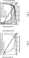
- the total energy requirement W tot. of the vacuum process shows Fig. 3 for different degrees of heat recovery of the heat exchangers used, which use the waste heat of the oxygen-depleted exhaust air to heat the fresh air. With 85% heat recovery (heat recovery rate) of the heat exchanger and 0.018 kWh / Sm 3 , the total energy consumption is just below that of a decentralized PSA system, even without using the waste heat from the oxygen cooling.
- the oxygen partial pressure at the feed outlet p OFout is used to implement an energy-efficient mode of operation.
- the oxygen partial pressure at the feed outlet p OFout and the vacuum pressure or the oxygen partial pressure, which is identical to it, on the permeate side p OSout are continuously measured.
- the air throughput is adjusted in terms of control technology so that the oxygen partial pressure at the feed outlet p OFout is not more than 100 mbar above the vacuum pressure p OSout , but in a preferred embodiment variant is not more than 20 mbar above it. In this way, a sufficiently low air throughput and a correspondingly high degree of oxygen separation are achieved in a wide operating range in order to ensure energy-efficient operation.
- An energetically highly efficient MIEC membrane system is characterized according to the invention by heating the fresh air via regenerative heat exchangers, which use more than 85%, in a preferred embodiment around 95% of the heat energy contained in the exhaust air and the waste heat released during the cooling of the oxygen to heat the air.
- the driving force for the oxygen transport is generated by applying a vacuum, as this minimizes the compression energy required and there is no need to recover it.
- the membrane system is operated in such a way that, in normal operation, a ratio of the incoming amount of fresh air to the amount of oxygen produced does not exceed 25: 1 and a ratio of 6: 1 does not is fallen below.
- the residual heat required to maintain the operating temperature of the membrane system is achieved by additional electrical heating or by metering in small amounts of fuel. As a result, in the latter case, a further reduction in the consumption of electrical energy can be achieved.
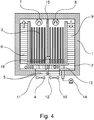
- the membrane system shown schematically for energy-efficient oxygen production consists, according to the invention, of a non-pressure-tight housing 1 with a metal connection plate 2 in which BSCF tubular membranes 3 closed on one side were inserted by means of silicone seals.
- a partition 15 with its opening 16 separates the interior of the housing into two chambers, which are constructed mirror-symmetrically with respect to the fresh air path.
- the fresh air is sucked in via a speed-controlled fan 4 upstream of the input 11, preheated by a regenerative heat exchanger 5 and passed through the divided connection plate 2 in order to absorb the heat of the extracted oxygen.
- the fresh air is then passed through a stationary regenerator 6 for further heating and is reheated to operating temperature with the additional heater 7.
- the air flow passes the BSCF tubular membranes 3 and the second additional heater 8 and gives off its heat to the further stationary regenerator 9.
- the already strongly cooled, oxygen-depleted air stream is then passed through the metal connection plate 2 to the regenerative heat exchanger 5 to those areas which are upstream of the outlet 12, where further heat is extracted from it.
- the speed-controlled fan 10 downstream of the output 12 works in cycle phase A in suction mode.
- the metallic connection plate 2 contains a vacuum-tight cavity structure 13 which is connected to the BSCF tubular membranes 3. The cavity of this cavity structure 13 is sucked off by an external vacuum pump 14. The pure oxygen is then available at ambient pressure.
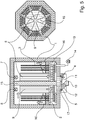
- the schematically illustrated membrane system for oxygen production consists, according to the invention, of a non-pressure-tight housing 1 with a metallic connection plate 2, in which BSCF tubular membranes 3 closed on one side were inserted by means of screwed cable connections.
- the housing 1 has an octagonal structure and is divided into eight chambers by eight partition walls 15, each partition wall being provided with an opening 16 in the area of the connection plate 2 so that the fresh air can flow through all chambers.
- the fresh air is sucked in via the speed-controlled fan 4 upstream of the input 11.
- the inlet 11 lies on a rotary valve 17 and is designed so large that the fresh air can flow into three chambers at the same time.
- the output 12 is also located on the rotary valve 17 and is preferably dimensioned the same as the input 11 and is opposite the input 11.
- the regenerative heat exchanger 5, which is arranged immediately downstream of the input 11, is at least dimensioned in such a way that when the rotary slide valve is rotated through 360 °, areas of the input 11 or output 12 are constantly covered.
- the fresh air sucked in by the upstream fan 4 through the inlet 11 is initially heated by areas of the regenerative heat exchanger 5. Further heating takes place by passing the segmented connection plate 2 and the following stationary regenerators 6 of the three chambers which are arranged downstream of the entrance.
- the additional heaters 7 arranged in the ceiling area are used to reheat the air flow.
- small amounts of fuel gas can also be used here.
- the heated fresh air then flows down between the partition walls 15 and through the Openings 16 in the opposite chambers. Up there, past the BSCF tubular membranes 3 and past the additional heaters 8, the fresh air that has already been depleted is now conducted past the stationary regenerators 9 of the respective chambers. Finally, the largely cooled fresh air is passed through the divided connection plate 2 and flows through those areas of the regenerative heat exchanger 5 that are open from the outlet 12. Further heat is extracted from the exhaust air flow.
- the speed-controlled downstream fan 10 always works in suction mode.
- the metallic connection plate 2 contains a vacuum-tight cavity structure 13 in which the oxygen obtained collects and is thus sucked off by an external vacuum pump 14.
- the constant rotation of the rotary slide 17 results in a permanent reversal of the fresh air supply direction in relation to the opposing chambers, ie the inlet 11 is at the outlet 12 after turning the rotary slide 17 by 180 ° and vice versa.
- the air throughput is regulated by the fan 4 upstream of the rotary valve 17 and the downstream fan 10 with variable speed so that the air throughput is 12 to 18 times the oxygen production rate.
Landscapes
- Chemical & Material Sciences (AREA)
- Chemical Kinetics & Catalysis (AREA)
- Analytical Chemistry (AREA)
- Inorganic Chemistry (AREA)
- Engineering & Computer Science (AREA)
- General Chemical & Material Sciences (AREA)
- Oil, Petroleum & Natural Gas (AREA)
- Organic Chemistry (AREA)
- Separation Using Semi-Permeable Membranes (AREA)
- Oxygen, Ozone, And Oxides In General (AREA)
Priority Applications (1)
| Application Number | Priority Date | Filing Date | Title |
|---|---|---|---|
| PL14755000T PL3022152T3 (pl) | 2013-07-17 | 2014-07-15 | Membranowy sposób separacji i instalacja membranowa do efektownego energetycznie wytwarzania tlenu |
Applications Claiming Priority (2)
| Application Number | Priority Date | Filing Date | Title |
|---|---|---|---|
| DE102013107610.6A DE102013107610A1 (de) | 2013-07-17 | 2013-07-17 | Membrantrennverfahren und Membrananlage zur energieeffizienten Erzeugung von Sauerstoff |
| PCT/DE2014/100255 WO2015007272A1 (de) | 2013-07-17 | 2014-07-15 | Membrantrennverfahren und membrananlage zur energieeffizienten erzeugung von sauerstoff |
Publications (2)
| Publication Number | Publication Date |
|---|---|
| EP3022152A1 EP3022152A1 (de) | 2016-05-25 |
| EP3022152B1 true EP3022152B1 (de) | 2020-09-30 |
Family
ID=51392017
Family Applications (1)
| Application Number | Title | Priority Date | Filing Date |
|---|---|---|---|
| EP14755000.8A Active EP3022152B1 (de) | 2013-07-17 | 2014-07-15 | Membrantrennverfahren und membrananlage zur energieeffizienten erzeugung von sauerstoff |
Country Status (8)
| Country | Link |
|---|---|
| US (1) | US9901866B2 (da) |
| EP (1) | EP3022152B1 (da) |
| CN (1) | CN105492380A (da) |
| DE (1) | DE102013107610A1 (da) |
| DK (1) | DK3022152T3 (da) |
| ES (1) | ES2834628T3 (da) |
| PL (1) | PL3022152T3 (da) |
| WO (1) | WO2015007272A1 (da) |
Cited By (1)
| Publication number | Priority date | Publication date | Assignee | Title |
|---|---|---|---|---|
| EP4563886A1 (de) | 2023-11-30 | 2025-06-04 | Messer SE & Co. KGaA | Verfahren und vorrichtung zum verbrennen eines brennstoffs unter einsatz von in einer membrananlage erzeugtem sauerstoff |
Families Citing this family (7)
| Publication number | Priority date | Publication date | Assignee | Title |
|---|---|---|---|---|
| US9834471B2 (en) * | 2015-11-17 | 2017-12-05 | King Fahd University Of Petroleum And Minerals | Sealing agent for ion transport membranes |
| DE102015119915A1 (de) * | 2015-11-18 | 2017-05-18 | Fraunhofer-Gesellschaft zur Förderung der angewandten Forschung e.V. | Verfahren und Vorrichtung zum Betrieb einer Gasturbine mit nasser Verbrennung |
| CN106006563B (zh) * | 2016-05-18 | 2018-03-02 | 中国航空工业集团公司西安飞机设计研究所 | 一种带有能量回收功能的离子传导膜制氧装置 |
| CN109626333B (zh) * | 2019-01-25 | 2019-12-31 | 北京汉华元生科技有限公司 | 一种电化学陶瓷膜产氧机及其制氧设备 |
| DE102019216764A1 (de) | 2019-10-30 | 2021-05-06 | Fraunhofer-Gesellschaft zur Förderung der angewandten Forschung e.V. | Vorrichtung umfassend zwei Teilsysteme, Verfahren zum Betreiben dieser Vorrichtung sowie Verkehrsmittel umfassend zumindest eines der Teilsysteme |
| WO2021252464A1 (en) | 2020-06-08 | 2021-12-16 | United States Of America As Represented By The Administrator Of Nasa | Systems and methods for oxygen concentration with electrochemical stacks in series gas flow |
| CN112708487B (zh) * | 2020-12-16 | 2022-02-15 | 山东师范大学 | 一种旋转膜分离装置及转化沼气制合成气系统和方法 |
Family Cites Families (15)
| Publication number | Priority date | Publication date | Assignee | Title |
|---|---|---|---|---|
| EP0024718A3 (de) | 1979-09-04 | 1981-10-14 | Friedrich Wolff | Vorrichtung zur Erhöhung oder Verminderung des Sauerstoffanteils der Luft sowie Verfahren zu deren Herstellung und Verfahren zu deren Betrieb |
| DE3273594D1 (en) | 1982-11-11 | 1986-11-06 | Matsushita Electric Industrial Co Ltd | High-temperature furnace having selectively permeable membranes for oxygen enrichment |
| DE3921390A1 (de) * | 1989-06-29 | 1991-01-17 | Merck Patent Gmbh | Verfahren und vorrichtung zur gewinnung von reinem sauerstoff |
| US5599383A (en) * | 1995-03-13 | 1997-02-04 | Air Products And Chemicals, Inc. | Tubular solid-state membrane module |
| EP0747108B1 (en) | 1995-06-07 | 2002-02-20 | Air Products And Chemicals, Inc. | Oxygen production by ion transport membranes with work recovery |
| US5935298A (en) * | 1997-11-18 | 1999-08-10 | Praxair Technology, Inc. | Solid electrolyte ionic conductor oxygen production with steam purge |
| US6537465B2 (en) * | 2000-12-29 | 2003-03-25 | Praxair Technology, Inc. | Low pressure steam purged chemical reactor including an oxygen transport membrane |
| US6702570B2 (en) | 2002-06-28 | 2004-03-09 | Praxair Technology Inc. | Firing method for a heat consuming device utilizing oxy-fuel combustion |
| WO2008014481A1 (en) | 2006-07-28 | 2008-01-31 | Rollins William S Iii | High efficiency integrated gasification combined cycle power plant |
| EP2026004A1 (de) | 2007-08-07 | 2009-02-18 | Siemens Aktiengesellschaft | Verfahren zum Betrieb einer Verbrennungsanlage sowie Verbrennungsanlage |
| EP2067937A2 (de) | 2007-08-27 | 2009-06-10 | Siemens Aktiengesellschaft | Verfahren zum Betrieb einer Kraftwerksanlage mit integrierter Vergasung sowie Kraftwerksanlage |
| JP2011517293A (ja) * | 2007-11-20 | 2011-06-02 | コーニング インコーポレイテッド | 酸素イオン伝導膜構造 |
| DE102007056841A1 (de) | 2007-11-23 | 2009-05-28 | Forschungszentrum Jülich GmbH | Membran-Kraftwerk und Verfahren zum Betreiben eines solchen |
| US8349214B1 (en) * | 2011-07-08 | 2013-01-08 | Praxair Technology, Inc. | Synthesis gas method and apparatus |
| US8945276B2 (en) * | 2013-06-07 | 2015-02-03 | Membrane Technology And Research, Inc. | Parallel feed gas separation membrane element assembly |
-
2013
- 2013-07-17 DE DE102013107610.6A patent/DE102013107610A1/de not_active Withdrawn
-
2014
- 2014-07-15 WO PCT/DE2014/100255 patent/WO2015007272A1/de not_active Ceased
- 2014-07-15 DK DK14755000.8T patent/DK3022152T3/da active
- 2014-07-15 PL PL14755000T patent/PL3022152T3/pl unknown
- 2014-07-15 CN CN201480040710.5A patent/CN105492380A/zh active Pending
- 2014-07-15 EP EP14755000.8A patent/EP3022152B1/de active Active
- 2014-07-15 ES ES14755000T patent/ES2834628T3/es active Active
- 2014-07-15 US US14/904,780 patent/US9901866B2/en active Active
Non-Patent Citations (1)
| Title |
|---|
| None * |
Cited By (2)
| Publication number | Priority date | Publication date | Assignee | Title |
|---|---|---|---|---|
| EP4563886A1 (de) | 2023-11-30 | 2025-06-04 | Messer SE & Co. KGaA | Verfahren und vorrichtung zum verbrennen eines brennstoffs unter einsatz von in einer membrananlage erzeugtem sauerstoff |
| DE102023133616A1 (de) * | 2023-11-30 | 2025-06-05 | Fraunhofer-Gesellschaft zur Förderung der angewandten Forschung eingetragener Verein | Verfahren und Vorrichtung zum Verbrennen eines Brennstoffs unter Einsatz von in einer Membrananlage erzeugtem Sauerstoff |
Also Published As
| Publication number | Publication date |
|---|---|
| US9901866B2 (en) | 2018-02-27 |
| PL3022152T3 (pl) | 2021-03-08 |
| ES2834628T3 (es) | 2021-06-18 |
| WO2015007272A1 (de) | 2015-01-22 |
| EP3022152A1 (de) | 2016-05-25 |
| CN105492380A (zh) | 2016-04-13 |
| DE102013107610A1 (de) | 2015-01-22 |
| DK3022152T3 (da) | 2020-11-23 |
| US20160136571A1 (en) | 2016-05-19 |
Similar Documents
| Publication | Publication Date | Title |
|---|---|---|
| EP3022152B1 (de) | Membrantrennverfahren und membrananlage zur energieeffizienten erzeugung von sauerstoff | |
| DE69501585T2 (de) | Hochtemperatur-Sauerstoffproduktion mit Dampf- und Energieerzeugung | |
| DE68926220T2 (de) | Verfahren und Vorrichtung zur Dampfkrafterzeugung | |
| DE69520965T2 (de) | Herstellung von Sauerstoff mit mehrstufigen leitenden Mischmembranen | |
| EP2214806B1 (de) | Membran-kraftwerk und verfahren zum betreiben eines solchen | |
| DE3879698T2 (de) | Membrantrennsystem und -prozess. | |
| DE112015003425T5 (de) | Hitzelose Adsorptionstrockenmethode und Vorrichtung für Lokomotive- Luftverdichter | |
| WO2010031366A2 (de) | Igcc-kraftwerk mit rauchgasrückführung und spülgas | |
| EP3129609A1 (de) | Verfahren und anlage zum speichern und rückgewinnen von energie | |
| DE102013103426B4 (de) | Verfahren und Membranmodul zur energieeffizienten Sauerstofferzeugung in der Biomassevergasung | |
| DE19943059B4 (de) | System zur Auskondensation einer Flüssigkeit aus einem Gasstrom | |
| EP3377818B1 (de) | Vorrichtung zum betrieb einer gasturbine mit nasser verbrennung | |
| DE3431186A1 (de) | Vorrichtung zur trinkwassergewinnung | |
| DE102014115849A1 (de) | Verfahren und Anordnung zur Erzeugung und thermischen Kompression von Sauerstoff | |
| EP2687282B1 (de) | Verfahren zum abscheiden von wasserstoff aus einem wasserstoffhaltigen gasgemisch in einer membran mit hohem spülgasdruck und vorrichtung zur durchführung dieses verfahrens | |
| DE442410C (de) | Verfahren und Vorrichtung zum Betrieb von Luft- und Gasfiltern | |
| DE102023133616A1 (de) | Verfahren und Vorrichtung zum Verbrennen eines Brennstoffs unter Einsatz von in einer Membrananlage erzeugtem Sauerstoff | |
| WO2015165432A2 (de) | Vorrichtung zur erzeugung einer temperaturdifferenz | |
| AT522219B1 (de) | Verfahren und Vorrichtung zur Konditionierung eines Gases | |
| DE19903353A1 (de) | Vorrichtung und Verfahren zur Befeuchtung und Verdichtung der Prozeßgase einer Brennstoffzellenanlage | |
| EP4172538A1 (de) | Verfahren und vorrichtung zur konditionierung eines gases | |
| EP1398070B1 (de) | Trennung von Stoffgemischen mittels Membranverfahren mit thermischer Konditionierung des Feedgemischs | |
| WO2010105803A1 (de) | Vorrichtung zur trennung von gasgemischen in ihre komponenten | |
| DE102007011879A1 (de) | Vorrichtung und Verfahren zur CO2-Abtrennung aus einem Prozessgas | |
| DE10254049A1 (de) | Direktgekühlter Ozongenerator |
Legal Events
| Date | Code | Title | Description |
|---|---|---|---|
| PUAI | Public reference made under article 153(3) epc to a published international application that has entered the european phase |
Free format text: ORIGINAL CODE: 0009012 |
|
| 17P | Request for examination filed |
Effective date: 20160217 |
|
| AK | Designated contracting states |
Kind code of ref document: A1 Designated state(s): AL AT BE BG CH CY CZ DE DK EE ES FI FR GB GR HR HU IE IS IT LI LT LU LV MC MK MT NL NO PL PT RO RS SE SI SK SM TR |
|
| AX | Request for extension of the european patent |
Extension state: BA ME |
|
| DAX | Request for extension of the european patent (deleted) | ||
| STAA | Information on the status of an ep patent application or granted ep patent |
Free format text: STATUS: EXAMINATION IS IN PROGRESS |
|
| 17Q | First examination report despatched |
Effective date: 20180711 |
|
| GRAP | Despatch of communication of intention to grant a patent |
Free format text: ORIGINAL CODE: EPIDOSNIGR1 |
|
| STAA | Information on the status of an ep patent application or granted ep patent |
Free format text: STATUS: GRANT OF PATENT IS INTENDED |
|
| RIC1 | Information provided on ipc code assigned before grant |
Ipc: B01D 53/22 20060101ALI20200414BHEP Ipc: B01D 71/02 20060101ALI20200414BHEP Ipc: B01D 63/06 20060101ALI20200414BHEP Ipc: C01B 13/02 20060101AFI20200414BHEP |
|
| INTG | Intention to grant announced |
Effective date: 20200504 |
|
| GRAS | Grant fee paid |
Free format text: ORIGINAL CODE: EPIDOSNIGR3 |
|
| GRAA | (expected) grant |
Free format text: ORIGINAL CODE: 0009210 |
|
| STAA | Information on the status of an ep patent application or granted ep patent |
Free format text: STATUS: THE PATENT HAS BEEN GRANTED |
|
| AK | Designated contracting states |
Kind code of ref document: B1 Designated state(s): AL AT BE BG CH CY CZ DE DK EE ES FI FR GB GR HR HU IE IS IT LI LT LU LV MC MK MT NL NO PL PT RO RS SE SI SK SM TR |
|
| REG | Reference to a national code |
Ref country code: GB Ref legal event code: FG4D Free format text: NOT ENGLISH Ref country code: CH Ref legal event code: EP |
|
| REG | Reference to a national code |
Ref country code: AT Ref legal event code: REF Ref document number: 1318613 Country of ref document: AT Kind code of ref document: T Effective date: 20201015 |
|
| REG | Reference to a national code |
Ref country code: DE Ref legal event code: R096 Ref document number: 502014014820 Country of ref document: DE |
|
| REG | Reference to a national code |
Ref country code: IE Ref legal event code: FG4D Free format text: LANGUAGE OF EP DOCUMENT: GERMAN |
|
| REG | Reference to a national code |
Ref country code: DK Ref legal event code: T3 Effective date: 20201118 |
|
| REG | Reference to a national code |
Ref country code: FI Ref legal event code: FGE |
|
| REG | Reference to a national code |
Ref country code: NL Ref legal event code: FP |
|
| PG25 | Lapsed in a contracting state [announced via postgrant information from national office to epo] |
Ref country code: HR Free format text: LAPSE BECAUSE OF FAILURE TO SUBMIT A TRANSLATION OF THE DESCRIPTION OR TO PAY THE FEE WITHIN THE PRESCRIBED TIME-LIMIT Effective date: 20200930 Ref country code: GR Free format text: LAPSE BECAUSE OF FAILURE TO SUBMIT A TRANSLATION OF THE DESCRIPTION OR TO PAY THE FEE WITHIN THE PRESCRIBED TIME-LIMIT Effective date: 20201231 Ref country code: BG Free format text: LAPSE BECAUSE OF FAILURE TO SUBMIT A TRANSLATION OF THE DESCRIPTION OR TO PAY THE FEE WITHIN THE PRESCRIBED TIME-LIMIT Effective date: 20201230 |
|
| PG25 | Lapsed in a contracting state [announced via postgrant information from national office to epo] |
Ref country code: RS Free format text: LAPSE BECAUSE OF FAILURE TO SUBMIT A TRANSLATION OF THE DESCRIPTION OR TO PAY THE FEE WITHIN THE PRESCRIBED TIME-LIMIT Effective date: 20200930 Ref country code: LV Free format text: LAPSE BECAUSE OF FAILURE TO SUBMIT A TRANSLATION OF THE DESCRIPTION OR TO PAY THE FEE WITHIN THE PRESCRIBED TIME-LIMIT Effective date: 20200930 |
|
| REG | Reference to a national code |
Ref country code: NO Ref legal event code: T2 Effective date: 20200930 |
|
| REG | Reference to a national code |
Ref country code: LT Ref legal event code: MG4D |
|
| PG25 | Lapsed in a contracting state [announced via postgrant information from national office to epo] |
Ref country code: CZ Free format text: LAPSE BECAUSE OF FAILURE TO SUBMIT A TRANSLATION OF THE DESCRIPTION OR TO PAY THE FEE WITHIN THE PRESCRIBED TIME-LIMIT Effective date: 20200930 Ref country code: EE Free format text: LAPSE BECAUSE OF FAILURE TO SUBMIT A TRANSLATION OF THE DESCRIPTION OR TO PAY THE FEE WITHIN THE PRESCRIBED TIME-LIMIT Effective date: 20200930 Ref country code: SM Free format text: LAPSE BECAUSE OF FAILURE TO SUBMIT A TRANSLATION OF THE DESCRIPTION OR TO PAY THE FEE WITHIN THE PRESCRIBED TIME-LIMIT Effective date: 20200930 Ref country code: RO Free format text: LAPSE BECAUSE OF FAILURE TO SUBMIT A TRANSLATION OF THE DESCRIPTION OR TO PAY THE FEE WITHIN THE PRESCRIBED TIME-LIMIT Effective date: 20200930 Ref country code: LT Free format text: LAPSE BECAUSE OF FAILURE TO SUBMIT A TRANSLATION OF THE DESCRIPTION OR TO PAY THE FEE WITHIN THE PRESCRIBED TIME-LIMIT Effective date: 20200930 Ref country code: PT Free format text: LAPSE BECAUSE OF FAILURE TO SUBMIT A TRANSLATION OF THE DESCRIPTION OR TO PAY THE FEE WITHIN THE PRESCRIBED TIME-LIMIT Effective date: 20210201 |
|
| PG25 | Lapsed in a contracting state [announced via postgrant information from national office to epo] |
Ref country code: AL Free format text: LAPSE BECAUSE OF FAILURE TO SUBMIT A TRANSLATION OF THE DESCRIPTION OR TO PAY THE FEE WITHIN THE PRESCRIBED TIME-LIMIT Effective date: 20200930 Ref country code: IS Free format text: LAPSE BECAUSE OF FAILURE TO SUBMIT A TRANSLATION OF THE DESCRIPTION OR TO PAY THE FEE WITHIN THE PRESCRIBED TIME-LIMIT Effective date: 20210130 |
|
| REG | Reference to a national code |
Ref country code: ES Ref legal event code: FG2A Ref document number: 2834628 Country of ref document: ES Kind code of ref document: T3 Effective date: 20210618 |
|
| PG25 | Lapsed in a contracting state [announced via postgrant information from national office to epo] |
Ref country code: SK Free format text: LAPSE BECAUSE OF FAILURE TO SUBMIT A TRANSLATION OF THE DESCRIPTION OR TO PAY THE FEE WITHIN THE PRESCRIBED TIME-LIMIT Effective date: 20200930 |
|
| REG | Reference to a national code |
Ref country code: DE Ref legal event code: R097 Ref document number: 502014014820 Country of ref document: DE |
|
| PLBE | No opposition filed within time limit |
Free format text: ORIGINAL CODE: 0009261 |
|
| STAA | Information on the status of an ep patent application or granted ep patent |
Free format text: STATUS: NO OPPOSITION FILED WITHIN TIME LIMIT |
|
| 26N | No opposition filed |
Effective date: 20210701 |
|
| PG25 | Lapsed in a contracting state [announced via postgrant information from national office to epo] |
Ref country code: SI Free format text: LAPSE BECAUSE OF FAILURE TO SUBMIT A TRANSLATION OF THE DESCRIPTION OR TO PAY THE FEE WITHIN THE PRESCRIBED TIME-LIMIT Effective date: 20200930 |
|
| PG25 | Lapsed in a contracting state [announced via postgrant information from national office to epo] |
Ref country code: MC Free format text: LAPSE BECAUSE OF FAILURE TO SUBMIT A TRANSLATION OF THE DESCRIPTION OR TO PAY THE FEE WITHIN THE PRESCRIBED TIME-LIMIT Effective date: 20200930 |
|
| PG25 | Lapsed in a contracting state [announced via postgrant information from national office to epo] |
Ref country code: IS Free format text: LAPSE BECAUSE OF FAILURE TO SUBMIT A TRANSLATION OF THE DESCRIPTION OR TO PAY THE FEE WITHIN THE PRESCRIBED TIME-LIMIT Effective date: 20210130 Ref country code: LU Free format text: LAPSE BECAUSE OF NON-PAYMENT OF DUE FEES Effective date: 20210715 |
|
| PG25 | Lapsed in a contracting state [announced via postgrant information from national office to epo] |
Ref country code: IE Free format text: LAPSE BECAUSE OF NON-PAYMENT OF DUE FEES Effective date: 20210715 |
|
| PG25 | Lapsed in a contracting state [announced via postgrant information from national office to epo] |
Ref country code: HU Free format text: LAPSE BECAUSE OF FAILURE TO SUBMIT A TRANSLATION OF THE DESCRIPTION OR TO PAY THE FEE WITHIN THE PRESCRIBED TIME-LIMIT; INVALID AB INITIO Effective date: 20140715 |
|
| P01 | Opt-out of the competence of the unified patent court (upc) registered |
Effective date: 20230524 |
|
| PG25 | Lapsed in a contracting state [announced via postgrant information from national office to epo] |
Ref country code: CY Free format text: LAPSE BECAUSE OF FAILURE TO SUBMIT A TRANSLATION OF THE DESCRIPTION OR TO PAY THE FEE WITHIN THE PRESCRIBED TIME-LIMIT Effective date: 20200930 |
|
| REG | Reference to a national code |
Ref country code: DE Ref legal event code: R082 Ref document number: 502014014820 Country of ref document: DE Representative=s name: GLEIM PETRI PATENT- UND RECHTSANWALTSPARTNERSC, DE |
|
| PG25 | Lapsed in a contracting state [announced via postgrant information from national office to epo] |
Ref country code: MK Free format text: LAPSE BECAUSE OF FAILURE TO SUBMIT A TRANSLATION OF THE DESCRIPTION OR TO PAY THE FEE WITHIN THE PRESCRIBED TIME-LIMIT Effective date: 20200930 |
|
| PG25 | Lapsed in a contracting state [announced via postgrant information from national office to epo] |
Ref country code: MT Free format text: LAPSE BECAUSE OF FAILURE TO SUBMIT A TRANSLATION OF THE DESCRIPTION OR TO PAY THE FEE WITHIN THE PRESCRIBED TIME-LIMIT Effective date: 20200930 |
|
| PGFP | Annual fee paid to national office [announced via postgrant information from national office to epo] |
Ref country code: NL Payment date: 20250723 Year of fee payment: 12 |
|
| PGFP | Annual fee paid to national office [announced via postgrant information from national office to epo] |
Ref country code: FI Payment date: 20250722 Year of fee payment: 12 Ref country code: ES Payment date: 20250819 Year of fee payment: 12 |
|
| PGFP | Annual fee paid to national office [announced via postgrant information from national office to epo] |
Ref country code: DK Payment date: 20250723 Year of fee payment: 12 Ref country code: DE Payment date: 20250722 Year of fee payment: 12 |
|
| PGFP | Annual fee paid to national office [announced via postgrant information from national office to epo] |
Ref country code: NO Payment date: 20250722 Year of fee payment: 12 |
|
| PGFP | Annual fee paid to national office [announced via postgrant information from national office to epo] |
Ref country code: PL Payment date: 20250707 Year of fee payment: 12 Ref country code: TR Payment date: 20250709 Year of fee payment: 12 Ref country code: IT Payment date: 20250731 Year of fee payment: 12 |
|
| PGFP | Annual fee paid to national office [announced via postgrant information from national office to epo] |
Ref country code: BE Payment date: 20250722 Year of fee payment: 12 Ref country code: GB Payment date: 20250724 Year of fee payment: 12 |
|
| PGFP | Annual fee paid to national office [announced via postgrant information from national office to epo] |
Ref country code: AT Payment date: 20250721 Year of fee payment: 12 Ref country code: FR Payment date: 20250723 Year of fee payment: 12 |
|
| PGFP | Annual fee paid to national office [announced via postgrant information from national office to epo] |
Ref country code: CH Payment date: 20250801 Year of fee payment: 12 Ref country code: SE Payment date: 20250723 Year of fee payment: 12 |